Embed Size (px)
Citation preview
1
Document No. IM-451 Rev NC-4.1h dated July 5, 2014
INSTALLATION AND OPERATION MANUAL
FOR
MODEL AK-451-( ) Series
406 MHz ELT Emergency Locator Transmitter with GPS/NAV position
AMERI - KING CORPORATION
17881 Sampson Lane Huntington Beach, CA 92648
Tel: (714) 842-8555
Fax: (714) 842-4235 Email: [email protected]
www.ameri-king.com
2
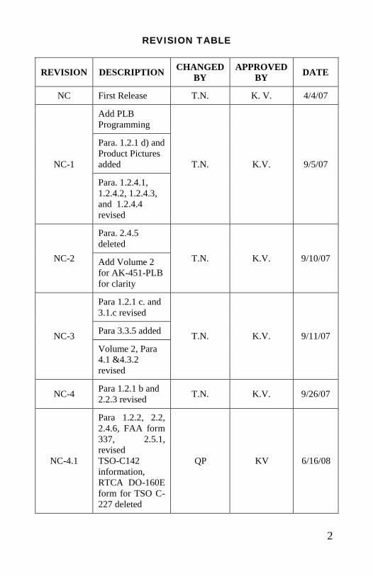
REVISION TABLE
REVISION DESCRIPTION CHANGED
BY
APPROVED
BY DATE
NC First Release T.N. K. V. 4/4/07
NC-1
Add PLB
Programming
T.N. K.V. 9/5/07
Para. 1.2.1 d) and
Product Pictures
added
Para. 1.2.4.1,
1.2.4.2, 1.2.4.3,
and 1.2.4.4
revised
NC-2
Para. 2.4.5
deleted
T.N. K.V. 9/10/07 Add Volume 2
for AK-451-PLB
for clarity
NC-3
Para 1.2.1 c. and
3.1.c revised
T.N. K.V. 9/11/07 Para 3.3.5 added
Volume 2, Para
4.1 &4.3.2
revised
NC-4 Para 1.2.1 b and
2.2.3 revised T.N. K.V. 9/26/07
NC-4.1
Para 1.2.2, 2.2,
2.4.6, FAA form
337, 2.5.1,
revised
TSO-C142
information,
RTCA DO-160E
form for TSO C-
227 deleted
QP KV 6/16/08
3
NC-4.1a
Revise: Para
2.5.1 & 3.5 to
meet Canadian
compliances
QP KV 10/22/08
NC-4.1b EASA Review
updated QP KV 10/31/08
NC-4.1c
EASA, T.C.
approved
updated
QP KV 11/26/08
NC-4.1d
Brazil Anatel
Approval
updated
T.N. KV 11/27/08
NC-4.1e
Japan Approval
Certificates
added
T.N. KV 11/30/08
NC-4.1f
FAA and EASA
Antenna
approvals added
T.N. KV 01/27/12
NC-4.1g
Clarify statement
for battery pack
service
T.N. KV 01/09/12
NC-4.1h
Delete Optional
Multi Axes G Sw Provision
(-12)(-16)
(-13)(-19)
KV KV 7/5/14
4
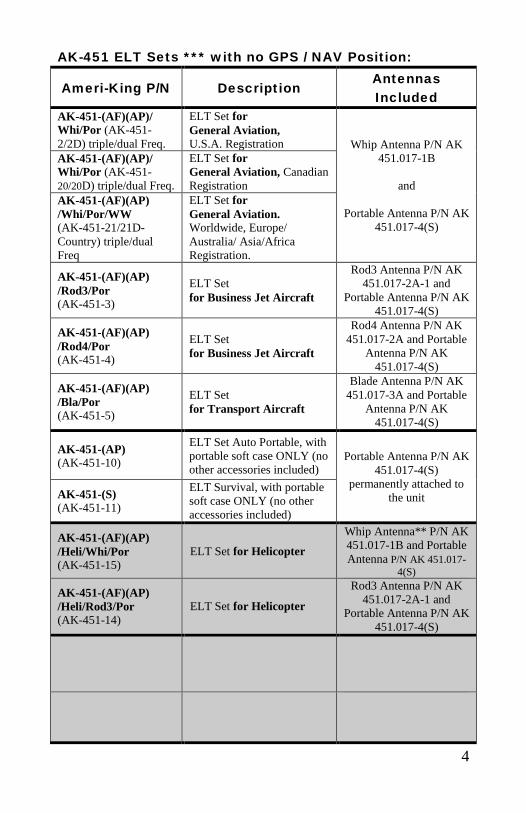
AK-451 ELT Sets *** with no GPS / NAV Position:
Ameri-King P/N Description
Antennas
Included
AK-451-(AF)(AP)/
Whi/Por (AK-451-
2/2D) triple/dual Freq.
ELT Set for
General Aviation, U.S.A. Registration Whip Antenna P/N AK
451.017-1B
and
Portable Antenna P/N AK
451.017-4(S)
AK-451-(AF)(AP)/
Whi/Por (AK-451-
20/20D) triple/dual Freq.
ELT Set for
General Aviation, Canadian
Registration
AK-451-(AF)(AP)
/Whi/Por/WW
(AK-451-21/21D-
Country) triple/dual
Freq
ELT Set for
General Aviation. Worldwide, Europe/
Australia/ Asia/Africa
Registration.
AK-451-(AF)(AP)
/Rod3/Por
(AK-451-3)
ELT Set
for Business Jet Aircraft
Rod3 Antenna P/N AK
451.017-2A-1 and
Portable Antenna P/N AK
451.017-4(S)
AK-451-(AF)(AP)
/Rod4/Por
(AK-451-4)
ELT Set
for Business Jet Aircraft
Rod4 Antenna P/N AK
451.017-2A and Portable
Antenna P/N AK
451.017-4(S)
AK-451-(AF)(AP)
/Bla/Por
(AK-451-5)
ELT Set
for Transport Aircraft
Blade Antenna P/N AK
451.017-3A and Portable
Antenna P/N AK
451.017-4(S)
AK-451-(AP)
(AK-451-10)
ELT Set Auto Portable, with
portable soft case ONLY (no
other accessories included) Portable Antenna P/N AK
451.017-4(S)
permanently attached to
the unit AK-451-(S)
(AK-451-11)
ELT Survival, with portable
soft case ONLY (no other
accessories included)
AK-451-(AF)(AP)
/Heli/Whi/Por
(AK-451-15)
ELT Set for Helicopter
Whip Antenna** P/N AK
451.017-1B and Portable
Antenna P/N AK 451.017-
4(S)
AK-451-(AF)(AP)
/Heli/Rod3/Por
(AK-451-14)
ELT Set for Helicopter
Rod3 Antenna P/N AK
451.017-2A-1 and
Portable Antenna P/N AK
451.017-4(S)

5
AK-451 ELT Sets *** with GPS / NAV Position:
Ameri-King P/N Description
Antennas
Included
AK-451-(AF)(AP) w/
GPS/Whi/Por
(AK-451-23/6) Triple Freq,
(AK-451-23D/6D/2D-GPS)
Dual Freq.
ELT Set, with GPS/NAV
Position, for General Aviation
Whip Antenna P/N AK
451.017-1B
and
Portable Antenna P/N
AK 451.017-4(S)
AK-451-(AF)(AP) w/
GPS/Rod3/Por
(AK-451-7)
ELT Set, with GPS/NAV
Position, for Business Jet
Aircraft
Rod3 Antenna P/N AK
451.017-2A-1
and
Portable Antenna P/N
AK 451.017-4(S)
AK-451-(AF)(AP) w/
GPS/Rod4/Por
(AK-451-8)
ELT Set, with GPS/NAV
Position, for Business Jet
Aircraft
Rod4 Antenna P/N AK
451.017-2A
and
Portable Antenna P/N
AK 451.017-4(S)
AK-451-(AF)(AP) w/
GPS/Blade/Por
(AK-451-9)
ELT Set, with GPS/NAV
Position, for Transport Aircraft
Blade Antenna P/N AK
451.017-3A
and
Portable Antenna P/N
AK 451.017-4(S)
AK-451-(AF)(AP) w/
GPS/Heli/Whip/Por
(AK-451-17)
ELT Set, for Helicopter, with
GPS/NAV Position.
Whip Antenna** P/N
AK 451.017-1B
and
Portable Antenna P/N
AK 451.017-4(S)
AK-451-(AF)(AP)w/ GPS /
Heli / Rod3 / Por
(AK-451-18)
ELT Set, for Helicopter, with
GPS/NAV Position.
Rod3 Antenna P/N AK
451.017-2A-1
and
Portable Antenna P/N
AK 451.017-4(S)
** Whip antenna must have separate approval for installation in a Helicopter (see para. 2.2.2)
*** Each Ameri-King ELT Set comes with dual Antennas, a FREE Soft Case (P/N SC-451) and
a FREE Accessory Set including Remote Switch Unit, Pre-Fabricated 25? Wiring Harness
Assembly, Audio Buzzer, T-Splitter, and 6? Coaxial Cable Assembly.
6
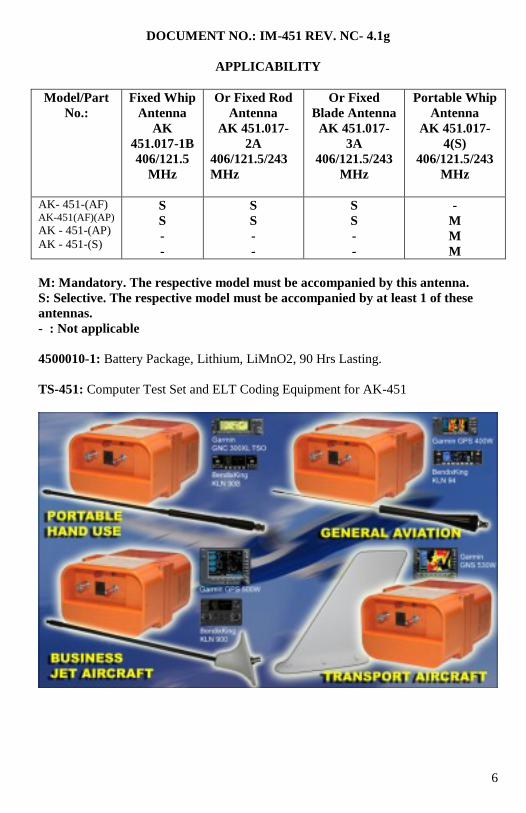
DOCUMENT NO.: IM-451 REV. NC- 4.1g
APPLICABILITY
Model/Part
No.:
Fixed Whip
Antenna
AK
451.017-1B
406/121.5
MHz
Or Fixed Rod
Antenna
AK 451.017-
2A
406/121.5/243
MHz
Or Fixed
Blade Antenna
AK 451.017-
3A
406/121.5/243
MHz
Portable Whip
Antenna
AK 451.017-
4(S)
406/121.5/243
MHz
AK- 451-(AF) AK-451(AF)(AP)
AK - 451-(AP)
AK - 451-(S)
S
S
-
-
S
S
-
-
S
S
-
-
-
M
M
M
M: Mandatory. The respective model must be accompanied by this antenna.
S: Selective. The respective model must be accompanied by at least 1 of these
antennas.
- : Not applicable
4500010-1: Battery Package, Lithium, LiMnO2, 90 Hrs Lasting.
TS-451: Computer Test Set and ELT Coding Equipment for AK-451
7
TABLE OF CONTENTS
Revision Page ..................................................................................................2
Table of Contents.............................................................................................7
List of Figures ..................................................................................................12
SECTION I
GENERAL INFORMATION
1.1 Scope ............................................................................................14
1.2 Overview ...........................................................................................14
1.2.1 Description .................................................................................14
1.2.2 Application and Equipment Limitation ......................................17
1.2.3 Certification ...............................................................................18
1.2.4 Programming ..............................................................................18
1.2.4.1 User Location Protocols (Long Message) ...........................18
1.2.4.2 Standard Location Protocols (Long Message) ....................19
1.2.4.3 National Location Protocols (Long Message) .....................19
1.2.4.4 User (non-location) Protocols (Short Message) ..................19
1.3 Technical Characteristics ..................................................................19
1.4 Accessories supplied .........................................................................24
1.4.1 Installation kit ............................................................................24
1.5 License requirement ..........................................................................24
SECTION II
INSTALLATION AND TEST
2.1 Unpacking and inspecting equipment................................................25
2.2 Mechanical installation......................................................................25
2.2.1 ELT main unit location and installation .....................................26
2.2.1.1 ELT Location Determination...........................................26
2.2.1.2 Mounting tray and Clamp Holder installation .................29
2.2.2 Antenna location and installation ...............................................33
2.2.2.1 Antenna location determination.......................................33
2.2.2.2 Antenna installation .........................................................35
2.2.2.2.1 Whip Antenna Installation ....................................35
2.2.2.2.2 Rod Antenna Installation ......................................40
2.2.2.2.3 Blade Antenna Installation ....................................43
2.2.2.2.4 Integral Antenna Installation ................................46
8
2.2.3 ELT remote unit location and installation ...................... 48
2.2.4 Wiring interconnecting harness ...................................... 51
2.2.5 Audible Monitor Location and Installation .................... 54
2.2.6 Wiring cable Installation................................................. 55
2.3 Electrical installation ........................................................................ 55
2.4 Post installation test .......................................................................... 55
2.5 Battery installation and replacement ................................................ 68
2.5.1 ELT main unit battery installation & replacement.......... 68
2.5.2 ELT remote unit battery installation & replacement ...... 71
2.6 FAA Form 337 ................................................................................. 72
SECTION III
OPERATION
3.1 General ........................................................................................ 73
3.2 Operation ........................................................................................ 74
3.3 Transmitter Functional Test ................................................................. 74
3.3.0 Quick Operation Check ......................................................... 75
3.3.1 Main Switch ON/OFF/ARM Operation ................................. 76
3.3.2 Transmitter ID Programming and Self-Test .......................... 76
3.3.3 System Integration Test ......................................................... 77
3.3.4 Green ON Lights, Buzzer Sound, and Antenna check ........... 80
3.3.5 Transmitter Functional Test for ELT-(S) only ....................... 81
3.4 Periodic Maintenance (Instructions for Continued Airworthiness) .... 86
3.4.1 Secure Inspection ................................................................... 86
3.4.2 Corrosion Inspection for Coaxial Cable ................................ 86
3.4.3 Corrosion Inspection for Remote Wiring Modular Cable ...... 86
3.4.4 Expiration Date Check ........................................................... 86
3.4.5 Battery Leakage Check .......................................................... 86
3.4.6 Operational Test..................................................................... 86
3.4.7.1 G-Switch Check ..................................................................... 86
3.4.7.2 Antenna Check....................................................................... 87
3.4.8 Verification of Digital Message ............................................. 87
3.4.9 Verification of Registration ................................................... 89
3.4.10 Verification of ELT/GPS interface ........................................ 90
3.4.10.1 ELT to GPS Interface Information ................................. 90
3.4.10.2 ELT/GPS Interface Communication Formats ................. 91
3.4.10.3 ELT/FMC Interface and Checkout Process .................... 92
9
3.4.10.4 24-Bit Address Installation Test (mandatory for
Installations reprogramming
by Ameri-King’s authorized dealer) ................................92
3.4.10.5 GPS Position Test ............................................................93
3.5 Periodic Maintenance (Instructions for Continued Airworthiness)
for Canadian Installation .......................................................................94
3.5.1 Regular Periodic Maintenance Test ........................................95
3.5.2 Power output test, Performance Testing .................................95
3.5.3 Frequency Test / Current Draw Test, Performance Testing ...97
3.5.4 Audio Modulation, Performance Testing ...............................99
3.5.5 Transmitter Functional Test ....................................................99
3.5.6 Performance Test Marking and Log Book Entry ....................99
3.5.7 Shipping ..................................................................................99
SECTION IV
REGISTRATION AND RESPONSIBLE USE
4.1 Registration .......................................................................................100
4.1.1 Registration importance ......................................................100
4.1.2 Where to register .................................................................100
4.1.3 Registration in the United States .........................................100
4.1.4 Registration in Canada ........................................................101
4.1.5 Registration outside of the United States and Canada ........101
4.1.6 Change of ownership or contact information ......................101
4.1.7 Lost ELT’s ..........................................................................102
4.1.8 Stolen ELT’s .......................................................................102
4.2 Responsibility ....................................................................................102
4.2.1 Responsible Use ..................................................................102
4.2.2 Preventing false alarms .......................................................103
4.2.3 Report false alarms..............................................................103
4.2.4 To report false alarms in the United States
contact any of the following ................................................103
SECTION V
WARRANTY AND SERVICE
5.1 Limited Warranty ..............................................................................104
5.2 Repair Service ...................................................................................105
5.3 Factory Comprehensive Test Service ................................................105
10
APPENDIX A
Retrofit Instructions from AK-450 to AK-451 .......................................................106
APPENDIX A.1
Quick Operation Check ..........................................................................................114
APPENDIX B
Periodic Maintenance Check List with Compliance Cross References ..................115
APPENDIX C
FAA Action Notice A 8150.3 Emergency Locator Transmitter recommended
Supplemental Inspection Procedure (FAR Part 91 Operations) ..............................119
APPENDIX D
Excerpt from FAA AC 91-44A Paragraph 8.a which defines when Battery
Replacement may be done under FAR 43.3 (h) as Preventive Maintenance ..........123
APPENDIX E
FAA Advisory Circular AC.13-2B, Section 37.C ..................................................124
APPENDIX F
Registering a 406 MHz Beacon for U.S.A..............................................................125
11
APPENDIX G
International 406 MHz Beacon Registration Database (IBRD)
Countries Allowing Individual Registration ........................................................... 128
APPENDIX H
ELT Coding Programming, ID Reader and Maintenance Test, P/N TS-451 .......... 133
APPENDIX I
RTCA DO-160D Environmental Qualification Forms ........................................... 145
APPENDIX I.1
RTCA DO-160E Environmental Qualification Forms ........................................... 147
APPENDIX J
Approval, FAA TSO C-126 / C-91a Equipment Approval dated 07/24/2008 ........ 150
Approval, Incomplete Technical Standard Order for ELT Antenna TSO C126
and C91a dated 11/4/2010 .................................................................... 152
Approval, EASA ETSO 2C-126/2C-91a EASA.IM.21O.1102
dated 11/20/2008 .................................................................................. 154
Approval, EASA ETSO 2C-126/2C-91a EASA.IM.21O.10033545
dated 1/27/2011 .................................................................................... 155
Approval, Transport Canada dated 11/26/2008 ...................................................... 156
Approval, Industry Canada, ID 2474A-A451PLAFAPS, dated 11/06/2008 .......... 158
Approval, Brazil Certificado Anatel, dated 03/31/2009 ......................................... 159
Approval, EASA Minor Change Approval 10027068, dated 9/3/2009 .................. 160
Approval, EASA Minor Change Approval 10027068 Rev 1, dated 1/10/2011 ...... 162
Approval, EASA Minor Change Approval 10026866, dated 8/18/2009 ................ 165
Approval, EASA Minor Change Approval 10026863, dated 8/18/2009 ................ 167
Approval, EASA Minor Change Approval 10026863 Rev 1, dated 11/15/2010 .... 169
Approval, EASA Minor Change Approval P-EASA.A.C.12674
dated 7/24/2009 .................................................................................... 171
Approval, Austria for "Historic Aircraft" like PA-18, 19 Series,
Bücker T131, JOB 15, CSS13, dated 4/16/2010 ................................... 174
Email Response from EASA to Ameri-King re. Acceptability of FAA
Form 8130-3 Export Form in EU Europe Union dated 10/2/2009 ....... 220
Approval, Japan Civil Aviation Board TSO C-126 and C91a ................................ 222
Approval, Japan Ministry of Internal Affairs and Communications Certificate ..... 224
Approval, COSPAS-SARSAT Type Approval Certificate No.179
dated 09/24/2007 .................................................................................. 226
APPENDIX K
Material Safety Data Sheet for Battery ................................................................... 229
12
List of Figures
Figure A: Front view of ELT .......................................................................... 23
Figure B: 3-D view of ELT ............................................................................. 23
Figure 1: Direction Determination for Fixed Wing Aircraft ........................... 28
Figure 1.1: Direction Determination for Helicopter ....................................... 29
Figure 2.1: Mounting Tray for ELT- (AF)(AP). P/N 450 013 ........................ 31
Figure 2.1a: Mounting Tray for ELT- (AP) with integral antenna & ELT-(S)
P/N 450 013-2 ........................................................................... 30
Figure 2.1.1: Optional Adapter Tray for ELT- (AF)(AP). P/N 450 013-1 ...... 38
Figure 2.1.2: ELT with mounting tray, holder, and adapter tray............. 39
Figure 2.2: Holder for ELT- (AF)(AP) P/N 450 014 ...................................... 31
Figure 2.2a: Holder for ELT-(AP) with integral antenna
P/N 450 014-1 ........................................................................... 30
Figure 3: Mounting Tray with Clamp Holder for ELT- (AF)(AP) ................. 32
Figure 4: Reserved
Figure 5: Antenna ground plane for nonmetallic aircraft ................................ 34
Figure 6: Whip Antenna (AK 451.017-1B) .................................................... 37
Figure 6.1: Reserved
Figure 7: Rod Antenna (AK 451.017-2A) ...................................................... 41
Figure 7.1: Rod Antenna (AK 451.017-2A-1) ................................................ 42
Figure 8: Blade Antenna (AK 451.017-3A) .................................................... 46
Figure 9: Integral Portable Whip Antenna (AK 451.017-4(S))
(Ant ground plane is not required) ................................................ 47
Figure 10: ELT Remote Switch Installation ................................................... 49
Figure 10.1: Mounting bracket for ELT Remote Unit (Continued) ................ 49
Figure 11: Remote Audio Buzzer Monitor P/N 451018 ................................ 50
Figure 11.1: Buzzer may be fastened directly onto the Remote Switch Unit . 51
Figure 12.1: Interconnecting Wiring Cable between ELT Remote Unit
and Main Unit, Part No. 4510041 ............................................. 52
Figure 12.2: Interconnecting Wiring Cable between ELT Remote Unit
and Main Unit, Part No. 4500041 ............................................. 53
Figure 13: Verify parameter setting ................................................................ 60
Figure 14.1a: Wiring diagram for AK-451 with 4-wire interconnecting
ELT Main Unit and Remote Switch Unit .................................. 62
Figure 14.1b: Wiring diagram for AK-451 with 2-wire interconnecting
ELT Main Unit and Remote Switch Unit .................................. 63
Figure 14.1c: Wiring Diagram for retrofitting AK-451 with 4-wire+
interconnecting ELT Main Unit and Remote Switch Unit,
Artex, Pointer, Kannad, ACK Tech, etc……………………………64
13
Figure 14.1d: Wiring Diagram for retrofitting AK-451 with 2-wire
interconnecting ELT Main Unit and Remote Switch Unit,
D&M, Narco, Joliet, etc. .......................................................................... 65
Figure 14.2a: Wiring Diagram for AK-451 with GPS Position
and 3-inch T adapter with 4-wire interconnecting ELT Main Unit
and Remote Switch Unit........................................................................... 66
Figure 14.2b: Wiring Diagram for AK-451 with GPS Position
and 3-inch T adapter with 2-wire interconnecting ELT Main Unit
and Remote Switch Unit........................................................................... 67
Figure 15: Battery Replacement for ELT Main Unit .............................................. 69
Figure 16: Battery Pack Replacement for ELT Main Unit (Actual View) ............. 70
Figure 16.1: Battery Cell Replacement for ELT Main Unit (Actual View) ........... 70
Figure 17: Battery Replacement for ELT Remote Unit .......................................... 71
Figure 18: ELT Front Panels-Main Unit and Remote Unit .................................... 78
Figure 19: ELT-(AP)(S) complete assembly with antenna ..................................... 83
Figure 20: Verify parameter setting ........................................................................ 93
14
SECTION I
GENERAL INFORMATION
1.1 SCOPE
This manual contains information necessary for the installation, test and operation of
the model AK-451, Emergency Locator Transmitter, manufactured by Ameri-King
Corporation, California, U.S.A.
1.2 OVERVIEW
1.2.1 Description
The Ameri-King AK-451-( ) Series is a FAA TSO’d approved, EASA ETSO’d
approved, 406 MHz ELT Emergency Locator Transmitter, Types (AF) Automatic
Fixed, (AP) Automatic Portable, (S) Survival. It transmits aircraft GPS/NAV position
data, immediately and accurately, on triple (406 Satellite /243 Military /121.5
Civilian) MHz frequencies. The supreme advantage feature is the aircraft GPS/NAV
Latitude / Longitude exact position shall be transmitted, within 1 minute, on the very
first burst, without waiting for a Polar Orbiting Satellite (could be up to 4 hours).
Enhance the accuracy significantly, for the ground search area, from 1-2 kilometers
(non GPS/ NAV Position) to 22 meters typical (with GPS/NAV Position). Having a
triple frequency insures your distress message reaches both NOAA Satellite
Operation and US Air Force AFSR Ground Operation, Search and Rescue Team, with
100% fully confidence, due to transmitting on both 243.0 MHz Military and 121.5
MHz Civilian bands, for immediate ground search dispatch, narrowing the searching
time.
The AK-451 ELT Emergency Locator Transmitter is micro controller based
equipment. It is extremely reliable equipment, designed to meet TSO-C126 and TSO-
C91A requirements, batteries operated and self contained.
The ELT Emergency Locator Transmitter is designed only for emergency use. The
model AK-451 may be used as one or more of the following ELT types:
a. Automatic Fixed-ELT (AF):
The ELT (AF) is designed to be permanently attached to the aircraft before and after a
crash. Aural and flashing light monitors are provided to alert the flight crew that the
ELT has been activated and is transmitting. It is designed to aid the Cospas-Sarsat
satellite and SAR teams in locating a crash site.
The model AK-451 (AF) consists of an ELT main unit, an aircraft-fixed antenna,
coaxial cable assembly, remote switch unit, interconnect wiring assembly, a T-adapter
connector, an audible buzzer monitor, a mounting tray, and clamp holders.
The ELT (AF) has an automatic activation G-Switch. It is activated automatically
upon a crash or manually operated.
15
b. Automatic Portable-ELT (AF) (AP) with dual antennas:
The ELT (AF) (AP) is designed to be rigidly attached to the aircraft before the crash,
but readily removable from the aircraft after a crash. It functions as an ELT (AF)
during a crash sequence. The aircraft mounted antenna may be disconnected and a
portable antenna (mounted on the ELT mounting tray) is then attached to the ELT.
All mentioned procedures require no tools. Flashing light indicator on the ELT is
provided to alert the user that the ELT has been activated and is transmitting. The
ELT can be tethered to a survivor or a life raft. It is designed to aid the Cospas-Sarsat
satellite and SAR teams in locating the crash site or survivor(s).
The model AK-451 (AF) (AP) consists of an ELT main unit, an aircraft-fixed
antenna, a portable antenna, coaxial cable assembly, remote switch unit, interconnect
wiring assembly, a T-adapter connector, an audible buzzer monitor, a mounting tray,
clamp holders and portable soft case..
The ELT (AF)(AP) has an automatic activation G-Switch. It is activated
automatically upon a crash or manually operated.
If for any reason, a fixed mounting is not required, the ELT (AF)(AP) can be used as
a Portable Device, due to it ‘s manual operated hand use Portability. Check Local
and/or national regulations for this issue.
c. Automatic Portable-ELT (AP) with integral antenna:
The ELT (AP) is designed to be rigidly attached to the aircraft before the crash, but
readily removable from the aircraft after a crash. It functions as an ELT (AF) during
a crash sequence. All mentioned procedures require no tools. Flashing light indicator
on the ELT is provided to alert the user that the ELT has been activated and is
transmitting. The ELT can be tethered to a survivor or a life raft. It is designed to aid
the Cospas-Sarsat satellite and SAR teams in locating the crash site or survivor(s).
The model AK-451 (AP) consists of an ELT main unit with an integral antenna,
remote switch unit, interconnect wiring assemblies, an audible buzzer monitor, a
mounting tray, clamp holders and portable soft case.
The ELT (AF) has an automatic activation G-Switch. It is activated automatically
upon a crash or manually operated.
If for any reason, a fixed mounting is not required, the ELT (AF)(AP) can be used as
a Portable Device, due to it ‘s manual operated hand use Portability. Check Local
and/or national regulations for this issue.
16
d. Survival-ELT (S, Category A):
The ELT (S) shall survive the shock, impact and crush tests, after a crash. This type
of ELT does not have automatic activation G-Switch and is intended to be removed
from the aircraft.
It functions as an ELT (P). Flashing light indicator on the ELT is provided to alert the
user that the ELT has been activated and is transmitting. The ELT can be tethered to a
survivor or a life raft. It is designed to aid the Cospas-Sarsat satellite and SAR teams
in locating the crash site or survivor(s).
The model AK-451-(S) consists of an ELT main unit with integral antenna and a
portable soft case.
The ELT (S) has no automatic activation G-Switch. It is activated manually only.
17
The Main Unit features include:
ON / OFF / ARM Main Switch
Green ON Light
RESET Push Button Switch
The Remote Unit features include:
ON Push Button Switch
Green ON Light
RESET Push Button Switch.
All functions of the AK-451 are under micro-controller control. A self-test routine
checks ELT operation and installation, then presents the results as visual and auditory
'error code' to aid in troubleshooting and to indicate status. Software is approved per
requirements of RTCA/DO-178B for level D software.
The battery pack consists of four D-size lithium, and is field replaceable. Rated life is
5 years or one hour of use, whichever comes first, as specified by FAR 91.207(c).
Installation kits are available that contain all major components needed to install the
beacon.
1.2.2 Application and Equipment Limitation
This manual constitutes FAA approved data as described in AC 43.9-1F, paragraph
(h)(2) and AC 43-210, chapter 2, paragraph 201(a)(6) for major alterations. Not all
installations are “major”; consult your local FAA ACO for clarification.
In Canada, Installation of an ELT in an aeronautical product is carried out under a
Supplemental Type Certificate (STC). This is a separate regulatory requirement and
should therefore refer to Ameri-King Document No. ICA-451 for the Operations and
Instructions for Continued Airworthiness (ICA).
The conditions and tests required for TSO approval of this article are minimum
performance standards. It is the responsibility of those desiring to install this
article on a specific type or class of aircraft to determine that the aircraft
installation conditions are within the TSO standards. TSO articles must have
separate approval for installation in an aircraft. The article may be installed
only if further evaluation by the applicant documents an acceptable installation
and it is approved by the FAA Administrator. The article may be installed only
if performed under 14 CFR parts 43 or the applicable airworthiness
requirement. For installations outside of the US, contact your local civil aviation
authority for guidance (Ref. TSO-C126 paragraph D).
Lithium battery safety concerns include the possibility of fire, venting violently,
and venting of toxic gases (Ref. TSO-C126 paragraph 5.a.(2)).
18
The AK-451 ELT described in this manual was designed, tested and certified as a
complete system including the following components:
ELT Transmitter w/ integral battery
ELT Mounting Tray and clamp Holder
ELT Antenna and Coaxial Cable Assembly
ELT Remote Switch and Remote Wiring Cable Assembly
ELT Audible Buzzer Monitor unit and T-Adapter Connector
Note:
Only Ameri-King approved system components may be used for a TSO approved
system.
1.2.3 Certification:
The AK-451 has been certified to the following:
FAA TSO-C126, C91a, C142
ETSO-2C126 per European Aviation Safety Agency (EASA)
FAR Part 91 – mandatory automatic ELT requirements
Cospas-Sarsat T.001
47 CFR Part 87 (FCC requirements) Note: Per FCC regulations 47
CFR § 2.902, the ELT is tested per “Verification” method.
Note:
The AK-451 is certified to meet the requirements of FAA TSO-C126, TSO-C91a and
EASA ETSO-2C126 per EUROCAE ED-62. For use outside the US or EASA
member states, contact your local civil aviation authority for ELT requirements.
1.2.4 Programming:
Ameri-King will program in any protocol at no charge. The AK-451 supports all
available worldwide ELT protocols in long message and short message. For a
complete ELT protocol, please see C/S document G.005 and T.001 available at
www.cospas-sarsat.com. For use outside the US, please contact your local civil
aviation authority for accepted or required programming protocols.
The AK-451 supports the following protocols:
1.2.4.1 User Location Protocols (Long Message):
Coding ELT with beacon serial identification
Coding ELT with aircraft operator designator and a serial number
Coding ELT with aircraft 24-bit address
Coding ELT with aircraft nationality and registration marking
19
1.2.4.2 Standard Location Protocols (Long Message):
Coding ELT with 24-bit address
Coding ELT with Type approval number and a serial number
Coding ELT with aircraft operator designator and a serial number
1.2.4.3 National Location Protocols (Long Message):
National Location Protocol (Coding for ELTs)
1.2.4.4 User (non-location) Protocol (Short Message):
Serial User Protocol Coded with ELTs Unique Beacon Serial Number.
Serial User Protocol Coded with the Aircraft Operator Designator and a
Serial Number.
Serial User Protocol Coded with the Aircraft 24-Bit Address.
Aviation User Protocol Coded with the Aircraft Nationality and
Registration Marking.
Note 1: The AK-451 is pre-programmed at the factory using ELT with C/S type
approval number and serial number, Standard Location Protocol (Long Message) or
Serial User Protocol (Short Message), for US aircraft.
Note 2: The AK-451 is pre-programmed at the factory using ELT with 24 Bit aircraft
address, Standard Location (Long Message) or Serial User (Short Message),
for Canadian aircraft. Your 24 Bit aircraft address, may be obtained from
http://www.tc.gc.ca/aviation/activepages/ccarcs/aspscripts/en/quicksearch.asp
Note 3: There is no electronic connection between TCAS or Mode S systems and the
ELT, only the ID number is common. The ELT may accept aircraft GPS/NAV
Lat/Long position data, then transmits the position data on the 406 MHz digital long
messages.
1.3 TECHNICAL CHARACTERISTICS
SPECIFICATIONS: CHARACTERISTICS: APPROVALS: FAA TSO-C126 / C91a, C142
and EASA ETSO-2C126/2C91a
BATTERIES:
4500010-1: Battery Pack, Lithium, LiMnO2, 90 Hrs lasting, 4D cells
Note: For Canadian aircraft installation, use 4500010-1 only.
4500010-2: Battery Pack, Lithium, LiSO2, 87 Hrs lasting, 4D cells
20
PHYSICAL CHARACTERISTICS:
SIZE AND WEIGHT:
Main Unit: (4.27”Wx2.95”Hx5.64”L) 1lbs 14oz
Remote Unit: (1.58”W x 0.65”H x 2.00”L) 1.0 oz
Transport Blade type, 451 017-3: 600 Knots airspeed, 1.4 lbs
Business Rod type, 451 017-2: 350 Knots airspeed, 0.5 lb
General Aviation whip type,
451 017-1: 300 Knots airspeed, 0.25 lb
Portable Antenna, 451 017-4: (17”L) 4.0 oz
Mounting Tray & Clamp holder: (4.51”W x 0.75”H x 5.87”L) 4.0 oz
MOUNTING HOLE SPACING:
Mounting Tray: 4 Trapezoid Corners (L1=2.76”; L2=1.76”; H=2.01”)
Remote Unit: 4 Rectangular Corners (1.825”W x 0.490”H)
Fixed Antenna: 7 / 5 / 1 Holes (0.500” Diameter) for Blade / Rod / Whip
respectively
CASE AND COLOR:
No Sharp Edges, High Impact, Flame Retorted, Fire Resistant, Waterproof, High,
Temperature ABS Plastic, Safety International Orange Color.
GENERAL SPECIFICATIONS (STANDARD CONDITIONS):
TRANSMITTER:
Operating Frequencies: 406.028 MHz ± 0.001 MHz
121.500 MHz ± 0.005 %
243.000 MHz ± 0.005 %
(Note: AK-451-2D/6D/20D/21D/23D will turn off 243 MHz)
Short term stability ≤ 2 x 10⁹
/100ms
Medium slope -1 to +1x10⁹
/min
Medium Residual variant ≤ 3 x 10⁹
Modulation
Characteristics: Audio Sweep Frequency: Download
Sweeping: (1600-300) Hz
Sweep Rate: 3 Hz ± 1 Hz
Modulation Factor: More than 0.85
Occupied Bandwidth: Less than 25 Hz
Voice Modulation: Included
Modulation Duty Cycle: (33-55) % Square Wave AM Continuous
Peak Effective Radiated50mW @ 121.5 MHz
RF Power (PERP): 50mW @ 125/243.0 MHz
5W +/- 1.58W @ 406.028 MHz
(35.34 to 38.18) dBm @ 406.028 MHz
21
Equivalent Isotropic 100mW (-10dBW) @121.5/243.0 MHz
(min)
Radiated Power (EIRP): 6dBW ± 4dB @406.028 MHz (max)
Emission Designator: 16K0G1D for 406.028 MHz
3K20A3X for 121.5 MHz
BATTERY REQUIREMENTS:
Transmitter Main Unit: Battery Pack consists of 4 cells, LiMnO2 or
LiSO2,“D” Size
Remote Unit: DURACELL DL 1/3 NB, or Equiv. Lithium Cell
AUTOMATIC CRASH ACTIVATION: Velocity Change of 2.3 ± 0.3 G (4.5 ± 0.5 FPS) per TSO C-126 (DO-
204A) and ETSO-2C126 (EUROCAE ED-62) requirement.
ANTENNA RADIATION CHARACTERISTICS: Radiation on 121.5, 243.0 MHz, and 406.028 MHz
Vertically polarized & Omni directional in the Horizontal Plane.
CRASHWORTHINESS: 100g, 23 ms, 6 directions
ACTIVATION MONITOR:
Manual ON and RESET functions are located on both ELT Main Unit and Remote
Unit. The two Green ON lights flashing, located on the ELT Main Unit and Remote
Switch Unit and a buzzer are to indicate when the ELT is transmitting. Both ELT
Main Unit and Remote Unit are self-powered by their internal batteries. Automatic
activation is remained, regardless whether the Cable Interconnect between the Main
Unit and the Remote Unit is open or shortened.
GPS INTERFACE PROTOCOL: Aviation RS-232
(Latitude/ Longititude Insert Messages) Baud Rate (fixed): 9600
Parity: None
Data Bits: 8
Stop Bits: 1
Garmin International Inc.:
• All Series: 150/ 250/ 400/420/430/ 500/520/530
Honeywell Bendix-King Inc.:
• KLN 88, KLN89, KLN89B, KLN 90, KLN90B, KLN94, KLN900.
22
Arnav Systems Inc.:
• R50, R50i, STAR 5000, FMS 5000, MFD (Multi-Functional Display).
II Morrow:
• FLYBUDDY, 2001 NMS
Trimble Nav Inc.:
• NAV 1000, NAV 2000, TNL 2100, and TNL3100. The following Trimble systems
all require a RS-422 to RS-232 adapter: NAV 3000, TNL 1000, TNL 2000, TNL
2000A, TNL 3000, 2000 APPROACH, 2000 APPROACH PLUS, 2101
APPROACH, 2101 APPROACH
PLUS, 2101 I/O APPROACH, 2101 I/O APPROACH PLUS.
ENVIRONMENTAL TEST SPECIFICATIONS:
RTCA DO-204; DO-183
TSO-C126/C91a, RTCA DO-160E ENV. CAT.: F1XBA (204/183)
(204/183)XR(204/183)XXSXXXXAC(204/183)BXXXX (204)
TEMP. AND ALTITUDE: Category F1
Low Temperature: -20°C Operating; -55°C Storage.
High Temperature: +55°C Operating; +85°C Storage.
OPERATING LIFE: 5W @ 406.208 MHz for 24 hrs @ 20°C
50mW @ 121.5 MHz
50mW @ 243.0 MHz
(Minimum Requirement throughout a 50
hour period at –20°C)
TEMP VARIATION: Category B, 10°C minimum per minute
HUMIDITY: Category A, 95% RH, 50 hours
operating
SHOCK: 500G, 4 ± 1msec
IMPACT: Penetration of 55 lbs mass, 6 drops, 4
surfaces
CRUSH: 1000 lbs, 4 surfaces
VIBRATION: 10G, Sinusoidal, (5-2000) Hz, 3 axes
WATERPROOF: Category R, 15 minutes Spray, 6 sides
IMMERSION SALT WATER: Category S, 24 hours Immersion, 160
hours at + 55°C
SALT SPRAY: Category S, 48 hours exposure to the
Salt Fog, and 48 hours drying
23
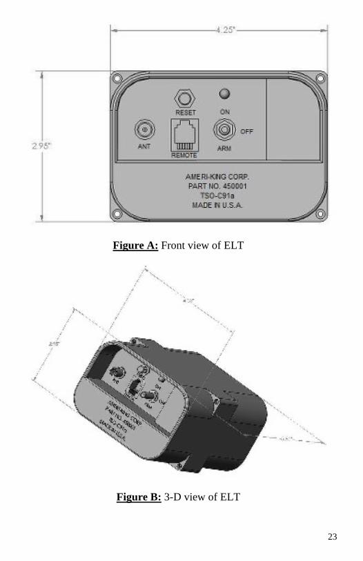
Figure A: Front view of ELT
Figure B: 3-D view of ELT
24
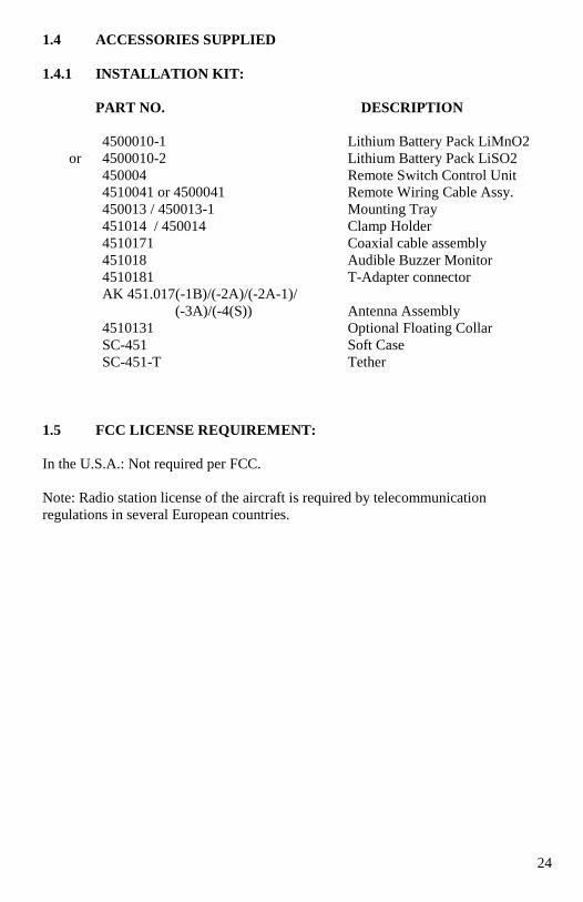
1.4 ACCESSORIES SUPPLIED
1.4.1 INSTALLATION KIT:
PART NO. DESCRIPTION
4500010-1 Lithium Battery Pack LiMnO2
or 4500010-2 Lithium Battery Pack LiSO2
450004 Remote Switch Control Unit
4510041 or 4500041 Remote Wiring Cable Assy.
450013 / 450013-1 Mounting Tray
451014 / 450014 Clamp Holder
4510171 Coaxial cable assembly
451018 Audible Buzzer Monitor
4510181 T-Adapter connector
AK 451.017(-1B)/(-2A)/(-2A-1)/
(-3A)/(-4(S)) Antenna Assembly
4510131 Optional Floating Collar
SC-451 Soft Case
SC-451-T Tether
1.5 FCC LICENSE REQUIREMENT:
In the U.S.A.: Not required per FCC.
Note: Radio station license of the aircraft is required by telecommunication
regulations in several European countries.
25
SECTION II
INSTALLATION AND TEST
2.1 UNPACKING AND INSPECTING EQUIPMENT
Handle with extreme care when unpacking the equipment. Visual inspection of the
equipment for evidence of damage incurred during shipment. Any claim should be
promptly filed with the transportation company. Save the shipping container to
substantiate the claim. Retain the container and packaging material for possible
future use.
2.2 MECHANICAL INSTALLATION
The ELT is designed with the installer in mind. All accessories, which are required
for complete ELT system installation, are provided, including Mounting Tray, Clamp
Holder, Coaxial Cable Assembly and Wiring Cable Assembly.
Because of the critical nature of an ELT, it is very important that the installation be
performed according to the following instructions. Installation of the ELT is
somewhat unique, as is the installation of any TSO-C126 and TSO-C91a ELT; it
requires experience in sheet metal work and avionics. Only licensed technicians
should install the ELT.
Many problems associated with the older ELTs were due to poor installation.
Therefore, duplicating a previous ELT installation with the AMERI-KING ELT may
not be acceptable.
Installations must be made by qualified personnel in accordance with FAA
regulations. Duplicating a previous installation may not be acceptable. Refer to the
Department of Transportation Regional ACO for detailed information.
Please refer to FAA AC 43.13 for guideline.
RTCA DO-182 recommends:
"All ELT system components which must survive a crash intact, should be attached to
the airframe in such a manner that the attachment system can support a 100g load ...in
the plus and minus directions of the three principal axes of the aircraft."
RTCA documents may be obtained from:
RTCA, Inc.
1828 L Street, NW
Suite 805
Washington, DC 20036
Tel: 202-833-9339
Fax: 202-833-9434
www.rtca.org
26
Note:
Installation in a pressurized aircraft constitutes a major modification. Consult the
Department of Transportation Regional Officer before proceeding.
Note: Aircraft manufacturers may also have guidance on ELT installation; refer to and
follow any applicable Type Approval or STC data for your aircraft. If located outside
of the US, follow all applicable regulations for your national authority.
By signing either the aircraft logbooks or the FAA Form 337, you are stating that the
installation has been performed in accordance with the current FARs and with the
steps and procedures outlined herein.
In Canada, all installations must be performed in accordance with the Engineering
and Inspection Manual Part II, Chapter III, Section 3.12.
Remember: Your Professional installation may save someone’s life.
2.2.1 ELT MAIN UNIT LOCATION AND INSTALLATION
2.2.1.1 ELT LOCATION DETERMINATION:
Many of the original ELT installations are inadequate as far as unit location and
surface rigidity are concerned. Just because the “old” ELT was located in a particular
position doesn’t mean the “new” ELT should be located there as well.
The tail section of an airplane is least likely to be damaged during a crash and
therefore, it provides a good mounting environment for the ELT unit. Refer to Figure
1 for Direction Determination for Fixed Wing Aircraft and Helicopter, respectively.
Accessibility of the unit is an important factor in the location of the ELT. Mount the
unit as far aft as practical but where it can be easily retrieved for maintenance.
The mounting surface must be extremely rigid; therefore, mounting the ELT directly
to the aircraft skin is unacceptable.
Mounting an ELT directly to the aircraft skin induces “crash hiding” vibration and
provides a very poor structural mounting surface. The mounting location must be
able to support 100 pounds of force in any direction with no appreciable distortion in
the structure. It must also be able to withstand a 350-pound force in any direction
without tearing or breaking the aircraft structure.
Please refer to FAA AC 43.13 for guideline.
27
Following are the FAA guidelines for mounting a TSO-C91a ELT, per RTCA
DO-183 paragraph 3.1.8:
1. “The ELT shall be mounted to primary aircraft load carrying structures such as
trusses bullheads, longerons, spars, or floor beams.”
2. “The mounts shall have a maximum static local deflection no greater than 2.5
mm (0.1 in) when a force of 451 Newtons (100lbs) is applied to the mount in the most
flexible direction. Deflection measurements shall be made with reference to another
part of the airframe not less than 0.3 meters (3 feet) from the mounting location.”
In addition, RTCA Document number DO-182 recommends that “all ELT system
components which must survive a crash intact, should be attached to the airframe in
such a manner that the attachment system can support a 100g load…in the plus and
minus directions of the three principal axes of the aircraft.”
The ELT must be mounted with the arrow which is printed on the battery case
pointing in the direction of flight. The ELT should be mounted with its longitudinal
axis aligned within 10 degrees of the longitudinal axis of the aircraft fuselage. Avoid
mounting the ELT near sources of strong EMI/RFI radiation. (See Fig. 1)
If this is a new installation or if the current installation is unacceptable, find a location
per the following:
RTCA suggests the aft section of the fuselage. Statistically, this is the least likely
section of the aircraft to receive damage in a crash. It is also near the antenna
connection, minimizing cable length between the transmitter and antenna. Maintain
access for maintenance. If possible, avoid locating the ELT where it will be subjected
to chemical fluids such as deicing compounds, cleaning fluids, etc. Over time, these
may attack the plastic and metal components.
The mounting location must conform to the requirements of RTCA DO-204 and AC
43.13-2B. DO-204 Sec 3.1.8 states:
"The ELT shall be mounted to primary aircraft load carrying structures such as
trusses, bulkheads, longerons, spars, or floor beams (not aircraft skin). The mounts
shall have a maximum static local deflection no greater than 2.5 mm (0.1 in.) when a
force of 450 Newton's (100 lbs) is applied to the mount in the most flexible direction.
Deflection measurements shall be made with reference to another part of the airframe
not less than 0.3 meters (1 foot) nor more than 1.0 m (three feet) from the mounting
location."
Separate mounting-hole patterns are provided so that, if the AK-451 is replacing an
existing ELT listed below, the original mounting holes can be used. Remove the old
ELT holder or tray and install the AK-451 mounting tray in its place. Stainless steel
hardware is recommended. Use hardware conforming to an accepted standard such as
AN or Mil-Spec.
28
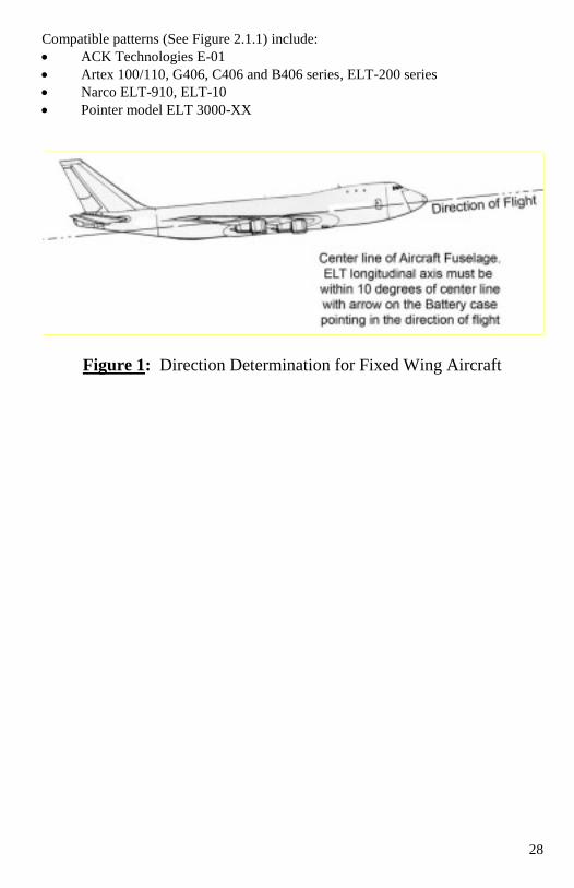
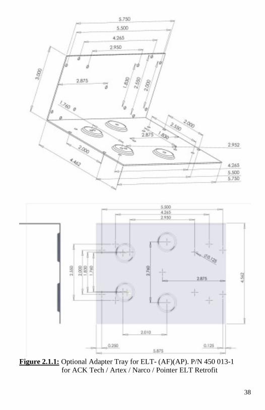
Compatible patterns (See Figure 2.1.1) include:
ACK Technologies E-01
Artex 100/110, G406, C406 and B406 series, ELT-200 series
Narco ELT-910, ELT-10
Pointer model ELT 3000-XX
Figure 1: Direction Determination for Fixed Wing Aircraft
29
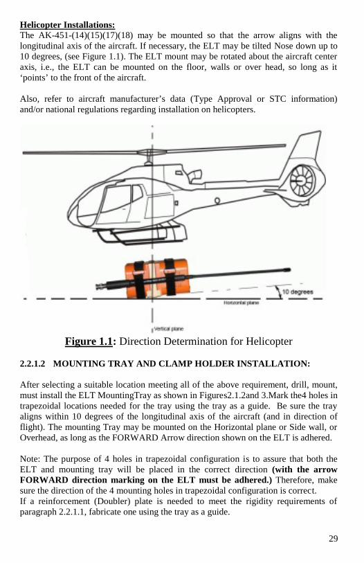
Helicopter Installations:
The AK-451-(14)(15)(17)(18) may be mounted so that the arrow aligns with the
longitudinal axis of the aircraft. If necessary, the ELT may be tilted Nose down up to
10 degrees, (see Figure 1.1). The ELT mount may be rotated about the aircraft center
axis, i.e., the ELT can be mounted on the floor, walls or over head, so long as it
‘points’ to the front of the aircraft.
Also, refer to aircraft manufacturer’s data (Type Approval or STC information)
and/or national regulations regarding installation on helicopters.
Figure 1.1: Direction Determination for Helicopter
2.2.1.2 MOUNTING TRAY AND CLAMP HOLDER INSTALLATION:
After selecting a suitable location meeting all of the above requirement, drill, mount,
must install the ELT MountingTray as shown in Figures2.1.2and 3.Mark the4 holes in
trapezoidal locations needed for the tray using the tray as a guide. Be sure the tray
aligns within 10 degrees of the longitudinal axis of the aircraft (and in direction of
flight). The mounting Tray may be mounted on the Horizontal plane or Side wall, or
Overhead, as long as the FORWARD Arrow direction shown on the ELT is adhered.
Note: The purpose of 4 holes in trapezoidal configuration is to assure that both the
ELT and mounting tray will be placed in the correct direction (with the arrow
FORWARD direction marking on the ELT must be adhered.) Therefore, make
sure the direction of the 4 mounting holes in trapezoidal configuration is correct.
If a reinforcement (Doubler) plate is needed to meet the rigidity requirements of
paragraph 2.2.1.1, fabricate one using the tray as a guide.
30
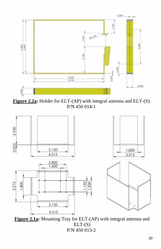
Figure 2.2a: Holder for ELT-(AP) with integral antenna and ELT-(S)
P/N 450 014-1
Figure 2.1a: Mounting Tray for ELT-(AP) with integral antenna and
ELT-(S)
P/N 450 013-2
31
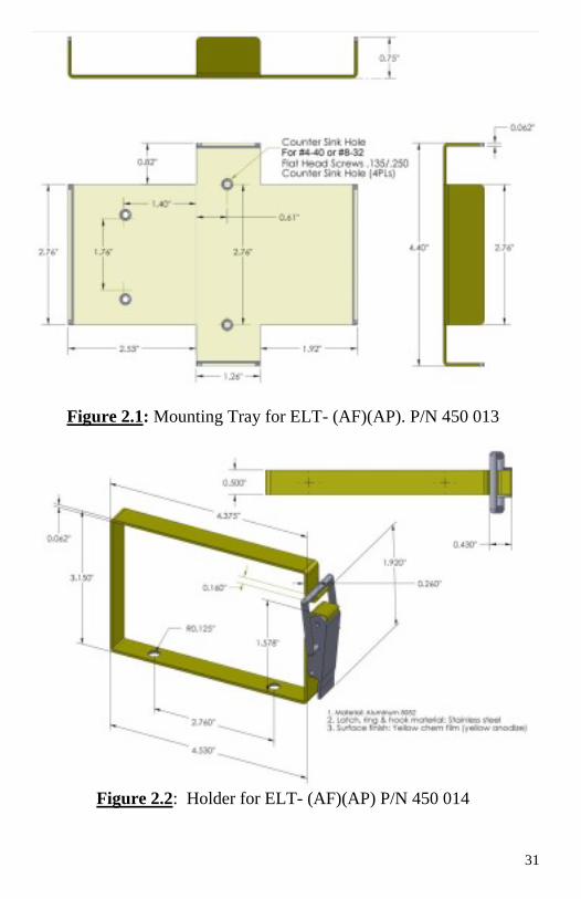
Figure 2.1: Mounting Tray for ELT- (AF)(AP). P/N 450 013
Figure 2.2: Holder for ELT- (AF)(AP) P/N 450 014
32
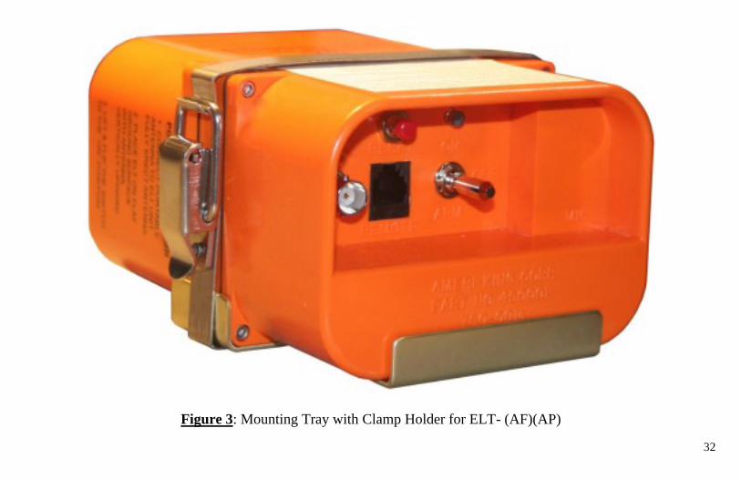
Figure 3: Mounting Tray with Clamp Holder for ELT- (AF)(AP)
33
2.2.2 ANTENNA LOCATION AND INSTALLATION
In order to meet the requirements of TSO-C91a and FAR 91.207, an External
Antenna must be used. The Portable Antenna (if supplied) with the unit is for use
only after the unit has been removed from the aircraft.
It is the responsibility of those desiring to install this article on a specific type or
class of aircraft to determine that the aircraft installation conditions are within
the TSO standards. All antennas must have separate approval for installation in
an aircraft. The article may be installed only if further evaluation by the
applicant documents an acceptable installation and it is approved by the FAA
Administrator. The article may be installed only if performed under 14 CFR
parts 43 or the applicable airworthiness requirement. For installations outside of
the US, contact your local civil aviation authority for guidance (Ref. TSO-C126
paragraph D).
Please refer to FAA AC 43.13 for guideline.
2.2.2.1 ANTENNA LOCATION DETERMINATION:
The mounting location of the External Antenna is determined to a great extent by the
mounting location chosen for the ELT Transmitter. The Antenna should be mounted
as close to the ELT Transmitter as practical. The Coaxial Cable connecting the
Antenna to the ELT should avoid crossing aircraft production breaks (i.e. riveted
fuselage sections). The Antenna must be within 20 degrees of vertical when the
aircraft is in a normal flight altitude. If the Antenna is mounted to a non-metallic
airframe, a supplementary ground plane must be installed. The installed Antenna
must be able to withstand a static load of 100 times its weight applied to the base of
the Antenna along the longitudinal axis of the aircraft. The Antenna should be placed
a minimum distance of 3 feet (1 meter) from any vertically polarized communication
Antennas (i.e. Antennas radiating in the 118-137 MHz band).
The AK-451 is certified to be used with any of the following antennas:
Whip antenna Model : AK 451.017-1B
Rod antenna Model: AK 451.017-2A
Blade antenna Model: AK 451.017-3A
Whip antenna Model: AK 451.017-4(S)
The ELT antenna must be mounted in accordance with the requirements of
RTCA/DO-204, Section 3.1.10 and RTCA/DO-183, Section 3.1.10. Locate the
antenna at least 30 inches away from other antennas, wires, vertical stabilizers, etc. to
minimize distortion of the radiated field and interference with other equipments. The
antenna must be installed VERTICALLY (within ± 15o of the vertical plane is
acceptable). Ameri-King has no performance data for installations that deviate from
the stated requirements.
34
Each of the above listed antennas requires a ground plane. On aircraft constructed
with non-conductive materials, such as composite or fiberglass, a ground plane must
be added. Ideally, the ground plane should extend out from the antenna mounting
point at least 24 inches in every direction. Many times this is not possible, but an
effective plane can be constructed as follow:
A 'doubler' layer of sheet metal, such as aluminum, can be mounted under the aircraft
skin. Alternatively, four or more 'radials' fastened to the underside of the fuselage
skin can be used to fashion a ground plane. Each radial can metallic type, 22 AWG
wire, etc. Tape should be at least 1 inch wide and each radial 24", minimum. The
ground plane connects to the shield of the RF antenna connector. Resistance between
the ground plane and shield connection should be maintained at 0.003Ω maximum. A
star washer should be used between the antenna connector housing and ground plane.
Take precautions to guard against corrosion, loosening, etc.
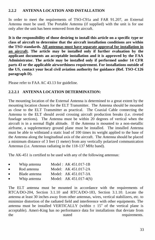
Ground Plane
On fabric-covered aircraft or aircraft with other types of nonmetallic skin, the
manufacturer’s recommendations should be followed in order to provide the
necessary ground plane. An acceptable method of accomplishing this is by providing
a number of metal foil strips in a radial position from the antenna base and secured
under the fabric or wood skin of the aircraft See diagram below:
Figure 5: - Antenna ground plane for nonmetallic aircraft
Note: THE LENGTH OF EACH FOIL RADIAL SHOULD BE AT LEAST
EQUAL TO THE ANTENNA LENGTH.
An effective, light-weight, ground plane formed from radial strips of copper foil. A
doubler may be required to reinforce the installation for resistance to impact,
vibration, ice, washing, etc. and can serve as connection points for the radials.
Specific antenna installation instructions follow. Also, AC 43.13-2B, paragraph 310
provides additional guidance for antenna installations.
35
2.2.2.2 ANTENNA INSTALLATION:
Please refer to FAA AC 43.13 for guideline.
After determining the Antenna mounting location per paragraph 2.2.2.1, install the
Antenna as shown in Figures 6, 7, 8 and 9.
1. Drill a ½” diameter hole or pattern holes in the aircraft structure at the Antenna
mounting location.
2. Install the Antenna and determine if the Antenna meets the static load
requirements. If not, a Double should be fabricated. A 100 time of antenna
weight force applied in the direction shown in Figure 3 should not cause an
appreciable distortion in the aircraft skin.
3. If the Antenna is being mounted on a non-conductive portion of the airframe, a
supplementary ground plane must be installed. The supplemental ground plane
must have a minimum diameter of 36” and be centered about the base of the
Antenna. This maybe provided using a conductive metallic coating
painted on the inside of the aircraft structure (SPRAYLAT Series 559 or
equivalent) or may be fabricated out of aluminum foil and attached to the inside
of the aircraft structure. A Doubler Plate should be used to provide increased
surface contact area between the ground plane and the Antenna.
4. Assemble of the Antenna as shown in Figure 3. Make sure the rubber washer,
which forms a moisture seal between the Antenna base and the aircraft structure
is in place before installing the Antenna. Also make sure the serrated locking
washing is in place.
2.2.2.2.1 Whip Antenna Installation: (AK 451.017-1B)
The AK 451.017-1B Whip Antenna delivers optimum performance only when
installed correctly. To ensure adequate structural strength of the aircraft for
associated air loading during flight, use of a backing plate or doublers (not supplied)
may be required. Refer to FAA Advisory Circular 43.13-2B for guidance. It is the
responsibility of the installation agency to determine the appropriate and adequate
antenna installation. The AK 451.017-1B Whip Antenna is designed to provide ELT
transmissions from a single BNC Female Coaxial connector.
Location:
The AK 451.017-1B must be mounted on the top of the aircraft to assure maximum
visibility of satellites (406 MHz). The best location is the upper aft portion of the
fuselage. It should be mounted vertically and away from projections such as a
propeller, tail surfaces, or the shadow of larger antennas. Refer to Fig. 6 for a drawing
of the antenna.
36
Installation Preparation:
1. Prepare the surface for antenna installations in such a manner to ensure a
ground contact of less than 0.003Ω. If bare metal surfaces are needed for
surface preparation they should be treated with Alodine® 1200(or similar
compound) to eliminate aluminum oxidation.
2. Drill 0.562" hole in aircraft skin.
Type of aircraft:
The AK 451.017-1B Whip Antenna is designed for installation on fixed wing
subsonic aircraft with reciprocating engines and is rated for a maximum airspeed of
300 KIAS (Knots Indicated Airspeed at Sea Level)
Installation:
1. Metal adapter plates are optional but they should be used if the curvature or
compound radius of the aircraft skin is such that antennas cannot be directly
installed vertically with their plates mounted flat to the aircraft outer surface.
2. Backing plates or doublers should be installed to ensure adequate structural
strength for associated air loading during flight. Refer to FAA Advisory
Circular 43.13-2B for complete information.
3. Remove the 1/2-28 hex nut and external tooth lock washer from the base of the
antenna. Insert antenna connector through mounting hole, make sure the "O"
ring remains in the base of the antenna connector flange groove and that the
connector has sufficient clearance through the aircraft skin. To mount the
antenna, place the lock washer and the hex nut on the inside of the aircraft and
sandwich the aircraft skin between the base of the antenna and lock washer
followed by the hex unit. Tighten the hex nut to between 25 to 30 inch lbs.
4. Apply a small, smooth fillet with RTV sealant around the periphery of the
antenna base to seal of moisture.
5. For maximum signal strength, the length of the antenna coax to the ELT
should be as short as possible (use of the standard 6-foot coax is recommended
when possible).
Composite Aircraft Installation:
Except for preparation instructions and installation of a ground plane, installation is
the same. Refer to FAA Advisory Circular 43.13-2B, Section 310 for complete
information. (See Appendix C)
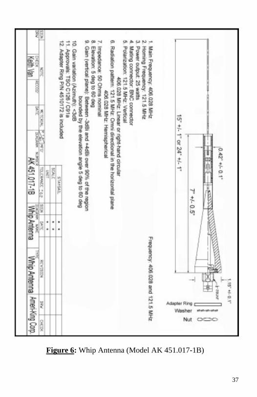
37
Figure 6: Whip Antenna (Model AK 451.017-1B)
38
Figure 2.1.1: Optional Adapter Tray for ELT- (AF)(AP). P/N 450 013-1
for ACK Tech / Artex / Narco / Pointer ELT Retrofit
39
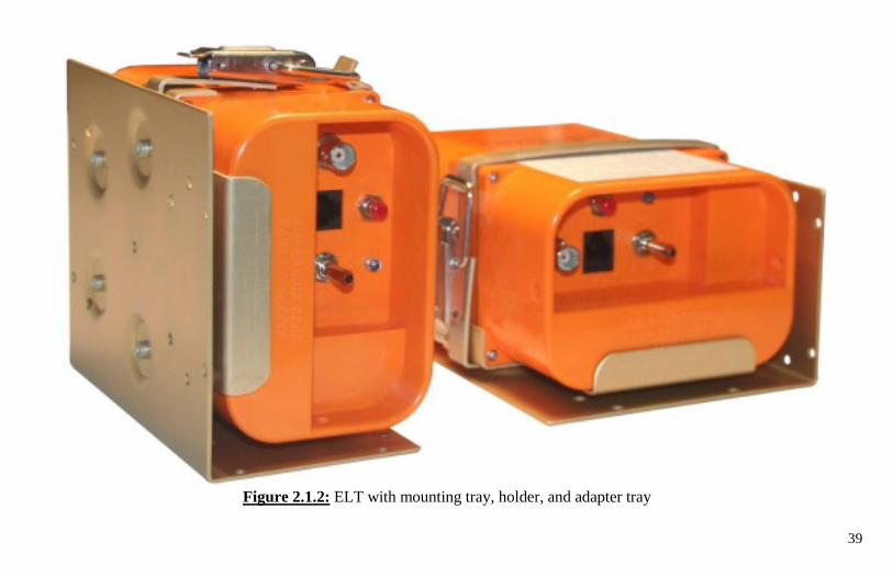
Figure 2.1.2: ELT with mounting tray, holder, and adapter tray
40
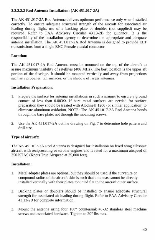
2.2.2.2.2 Rod Antenna Installation: (AK 451.017-2A)
The AK 451.017-2A Rod Antenna delivers optimum performance only when installed
correctly. To ensure adequate structural strength of the aircraft for associated air
loading during flight, use of a backing plate or doubler (not supplied) may be
required. Refer to FAA Advisory Circular 43.13-2B for guidance. It is the
responsibility of the installation agency to determine the appropriate and adequate
antenna installation. The AK 451.017-2A Rod Antenna is designed to provide ELT
transmissions from a single BNC Female coaxial connector.
Location:
The AK 451.017-2A Rod Antenna must be mounted on the top of the aircraft to
assure maximum visibility of satellites (406 MHz). The best location is the upper aft
portion of the fuselage. It should be mounted vertically and away from projections
such as a propeller, tail surfaces, or the shadow of larger antennas.
Installation Preparation:
1. Prepare the surface for antenna installations in such a manner to ensure a ground
contact of less than 0.003Ω. If bare metal surfaces are needed for surface
preparation they should be treated with Alodine® 1200 (or similar application) to
eliminate aluminum oxidation. NOTE: The AK 451.017-2A Rod Antenna bonds
through the base plate, not through the mounting screws.
2. Use the AK 451.017-2A outline drawing on Fig. 7 to determine hole pattern and
drill size.
Type of aircraft:
The AK 451.017-2A Rod Antenna is designed for installation on fixed wing subsonic
aircraft with reciprocating or turbine engines and is rated for a maximum airspeed of
350 KTAS (Knots True Airspeed at 25,000 feet).
Installation:
1. Metal adapter plates are optional but they should be used if the curvature or
compound radius of the aircraft skin is such that antennas cannot be directly
installed vertically with their plates mounted flat to the aircraft outer surface.
2. Backing plates or doublers should be installed to ensure adequate structural
strength for associated air loading during flight. Refer to FAA Advisory Circular
43.13-2B for complete information.
3. Mount the antenna using four 100° countersink #8-32 stainless steel machine
screws and associated hardware. Tighten to 20” lbs max.
41
4. Apply a layer of anti-corrosion bonding grease between aircraft skin and bottom
of antenna.
5. Apply a small, smooth fillet with RTV sealant around the periphery of the
antenna base to seal out moisture.
6. For maximum signal strength, the length of the antenna coax cable to the ELT
should be as short as possible (use of the standard 6 foot coax cable is
recommended when possible).
Figure 7: Rod Antenna AK 451.017-2A
42
Figure 7.1: Rod Antenna AK 451.017-2A-1
43
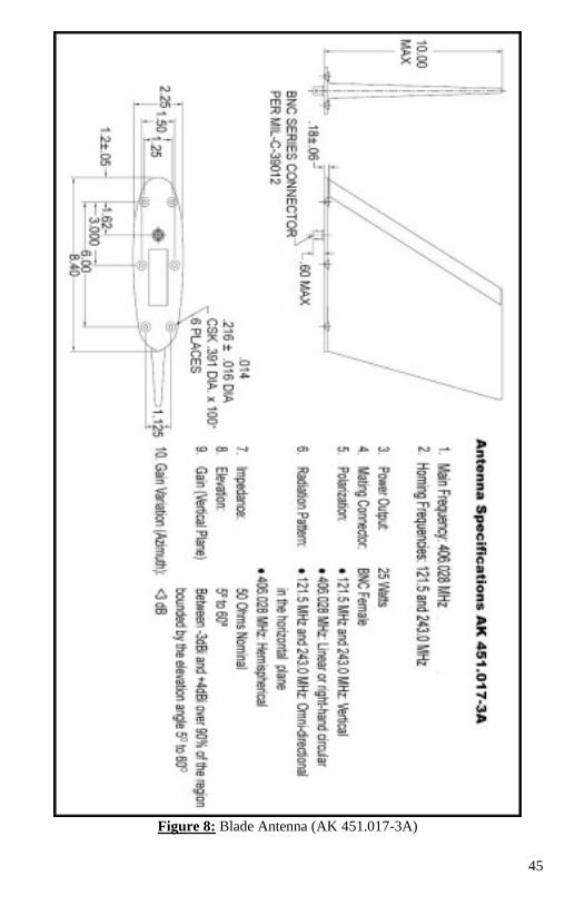
2.2.2.2.3 Blade Antenna Installation: (AK 451.017-3A)
Installations must be made by qualified personnel, and in accordance with Federal
Regulations. The AK 451.017-3A Blade Antenna delivers optimum performance
only when installed correctly. To ensure adequate structural strength of the aircraft
for associated air loading during flight, use of a backing plate or doublers (not
supplied) may be required. Refer to FAA Advisory Circular 43.13-2B for guidance.
Look for Advisory Circulars under the Regulatory/Advisory heading on the FAA
home page, www.faa.gov. It is the responsibility of the installation agency to
determine the appropriate and adequate antenna installation. The AK 451.017-3A
Blade Antenna is designed to provide ELT transmissions from a single BNC Female
Coaxial connector.
Location:
The AK 451.017-3A must be mounted on the top of the aircraft to assure maximum
visibility of satellites (406 MHz). The best location is the upper aft portion of the
fuselage. The specific mounting location is very important. A flat surface is the best
antenna mounting location. Do not mount the antenna on the curvatures and uneven
surface. It should be mounted vertically and away from projections such as a
propeller, tail surfaces, engine exhaust, or the shadow of larger antennas. Do not over
torque the mounting screws in an attempt to reduce gaps between the antenna base
plate and aircraft mounting surface. If gaps over 0.020” appear between the base
plate and mounting surface, use of a mounting saddle is recommended. Refer to Fig.
8 for a drawing of the antenna.
Installation Preparation:
Prepare the surface for blade antenna installations in such a manner to ensure a
ground contact of less than 0.003Ω. The electrical bonding between the antenna and
the aircraft ground is very important. If this bonding is not done properly, the
performance of the antenna may become distorted and nulls may appear in the
antenna radiation pattern. This, in turn, may cause erratic navigational readings or
signal drop out. The electrical bonding of the antennas to the aircraft skin is best
accomplished by direct metal-to-metal contact of the antenna base to the aircraft
skin. To accomplish this, the aircraft paint in the mounting area will need to be
removed. If bare metal surfaces are needed for surface preparation they should be
treated with Alodine® 1200(or similar compound) to eliminate aluminum oxidation.
After installing the blade antenna, make sure the electrical bonding of the antenna
base blade to the aircraft meets the requirement of less than 0.003Ω.
Type of aircraft:
The AK 451.017-3A Blade Antenna is designed for installation on fixed wing
subsonic aircraft with reciprocating engines and is rated for a maximum airspeed of
600 KIAS (Knots Indicated Airspeed at Sea Level)
44
Installation:
1. Mounting the Blade antenna using #10-32 SS machine screws and associated
hardware and torque to 20 in-lbs.
2. For BNC connector, drill a 0.6250” (5/8”) diameter hole.
3. The most important in installing Blade antenna is the electrical bonding
between the base plate antenna and the aircraft skin (metal-to-metal) rather
than thru the mounting screws as some other antennas.
4. A layer of anti-corrosion bonding grease should be applied between the aircraft
skin and the base of the antenna.
5. Metal adapter plates are optional but they should be used if the curvature or
compound radius of the aircraft skin is such that antennas cannot be directly
installed vertically with their plates mounted flat to the aircraft outer surface.
6. Backing plates or doublers should be installed to ensure adequate structural
strength for associated air loading during flight. Refer to FAA Advisory
Circular 43.13-2B for complete information.
7. Remove the 1/2-28 hex nut and external tooth lock washer from the base of the
antenna. Insert antenna connector through mounting hole, make sure the "O"
ring remains in the base of the antenna connector flange groove and that the
connector has sufficient clearance through the aircraft skin. To mount the
antenna, place the lock washer and the hex nut on the inside of the aircraft and
sandwich the aircraft skin between the base of the antenna and lock washer
followed by the hex unit. Tighten the hex nut to between 25 to 30 in-lbs.
8. Apply a small, smooth fillet with RTV sealant around the periphery of the
antenna base to seal of moisture.
9. For maximum signal strength, the length of the antenna coax to the ELT should
be as short as possible (use of the standard 6-foot coax is recommended when
possible).
45
Figure 8: Blade Antenna (AK 451.017-3A)
46
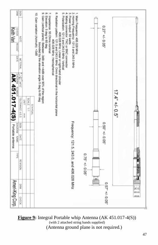
2.2.2.2.4 Integral Antenna Installation: (AK 451.017-4(S))
The integral Antenna AK 451.017-4(S) is fastened to the ELT-(AP) with Integral
Antenna, ELT-(S). This Antenna required no ground plane. The antenna ground
plane installation is not required.
Type of aircraft:
The AK 451.017-4(S) Integral Antenna is designed for installation for any aircraft
including fix wing and helicopters.
Installation:
Installation is not required.
The AK-451 (AP) with Integral Antenna and AK-451-(S) are the best ELT
configurations for composite aircraft because the Antenna ground plane is not
required.
47
Figure 9: Integral Portable whip Antenna (AK 451.017-4(S)) (with 2 attached string bands supplied)
(Antenna ground plane is not required.)

48
49
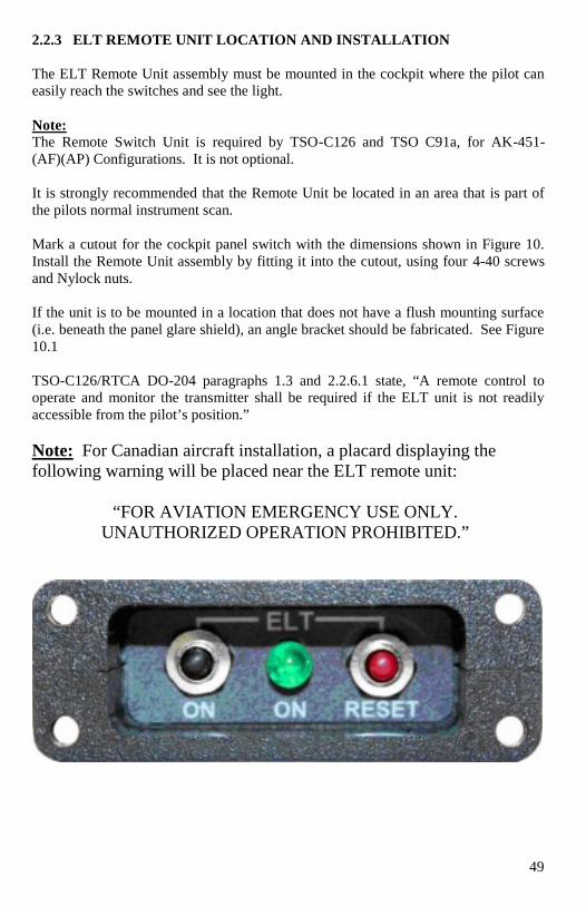
2.2.3 ELT REMOTE UNIT LOCATION AND INSTALLATION
The ELT Remote Unit assembly must be mounted in the cockpit where the pilot can
easily reach the switches and see the light.
Note:
The Remote Switch Unit is required by TSO-C126 and TSO C91a, for AK-451-
(AF)(AP) Configurations. It is not optional.
It is strongly recommended that the Remote Unit be located in an area that is part of
the pilots normal instrument scan.
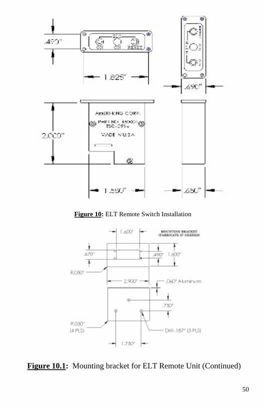
Mark a cutout for the cockpit panel switch with the dimensions shown in Figure 10.
Install the Remote Unit assembly by fitting it into the cutout, using four 4-40 screws
and Nylock nuts.
If the unit is to be mounted in a location that does not have a flush mounting surface
(i.e. beneath the panel glare shield), an angle bracket should be fabricated. See Figure
10.1
TSO-C126/RTCA DO-204 paragraphs 1.3 and 2.2.6.1 state, “A remote control to
operate and monitor the transmitter shall be required if the ELT unit is not readily
accessible from the pilot’s position.”
Note: For Canadian aircraft installation, a placard displaying the
following warning will be placed near the ELT remote unit:
“FOR AVIATION EMERGENCY USE ONLY.
UNAUTHORIZED OPERATION PROHIBITED.”
50
Figure 10: ELT Remote Switch Installation
Figure 10.1: Mounting bracket for ELT Remote Unit (Continued)
51
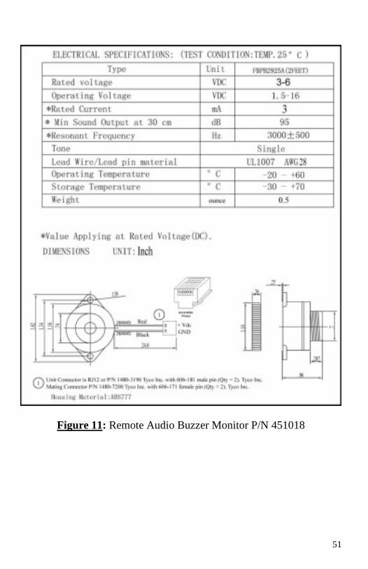
Figure 11: Remote Audio Buzzer Monitor P/N 451018
52
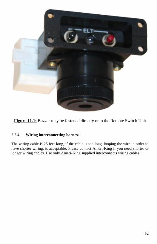
Figure 11.1: Buzzer may be fastened directly onto the Remote Switch Unit
2.2.4 Wiring interconnecting harness
The wiring cable is 25 feet long, if the cable is too long, looping the wire in order to
have shorter wiring, is acceptable. Please contact Ameri-King if you need shorter or
longer wiring cables. Use only Ameri-King supplied interconnects wiring cables.
53
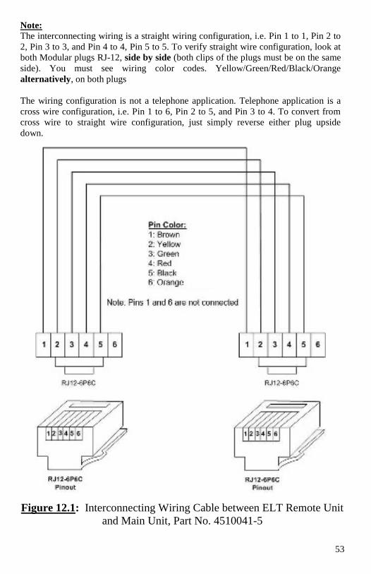
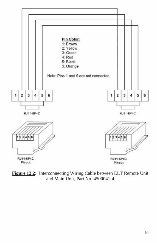
Note: The interconnecting wiring is a straight wiring configuration, i.e. Pin 1 to 1, Pin 2 to
2, Pin 3 to 3, and Pin 4 to 4, Pin 5 to 5. To verify straight wire configuration, look at
both Modular plugs RJ-12, side by side (both clips of the plugs must be on the same
side). You must see wiring color codes. Yellow/Green/Red/Black/Orange
alternatively, on both plugs
The wiring configuration is not a telephone application. Telephone application is a
cross wire configuration, i.e. Pin 1 to 6, Pin 2 to 5, and Pin 3 to 4. To convert from
cross wire to straight wire configuration, just simply reverse either plug upside
down.
Figure 12.1: Interconnecting Wiring Cable between ELT Remote Unit
and Main Unit, Part No. 4510041-5
54
Figure 12.2: Interconnecting Wiring Cable between ELT Remote Unit
and Main Unit, Part No. 4500041-4
55
2.2.5 Audible Monitor Location and Installation:
A warning buzzer is required for TSO-C126 approval. The buzzer (P/N 451018) is
powered by the ELT system and, therefore, independent of the aircraft power system.
When the ELT is activated, the buzzer 'beeps' periodically. The time between pulses
lengthen after a predetermined transmitter 'on' time. While the buzzer may be located
anywhere on the aircraft, it is recommended that the buzzer be placed in the cockpit,
near to the Remote Switch Unit. This buzzer operates in tandem with the ELT panel
indicator and would serve as a redundant indicator.
Note: RTCA/DO-204 indicates installation in the cockpit.
The buzzer can be mounted on the instrument panel, using the plastic bezel nut.
Suggested mounting is with the buzzer orifice with an open hole on the instrument
panel, adjacent to the Remote Switch Unit. The 2 mounting ears at its base may be
used as an extra optional mounting secure on the instrument panel.
Another option is tie wrapped the Buzzer, onto the Aircraft Wiring Harness, or
attached by tiewrap onto or behind the Instrument Panel, or fasten directly onto the
Remote Switch Unit (See Figure 11.1).
Connect the Buzzer wiring to the Remote Switch Unite via T-Adapter connector. The
rear of the buzzer can be sealed with RTV; however, the front must be left open.
Note: If the Buzzer for AK-451 is located inside the ELT Main Unit, it is powered by
the ELT Main batteries. The ELT Main Batteries will continue to supply power to the
Buzzer for 78 hours at -20 deg C, at end of 5 years battery life.
Connect Harness:
With the harness installed (See Fig. 14) into the Remote Switch Unit. Install the ELT
in its mounting tray, securing with the Clamp holder. Connect the buzzer wires.
Note: Splicing may be necessary on the buzzer wire, If more than 4’ long. Connector
is to be sealed with RTV after system has been tested.
Once all tests have satisfactorily been completed and all harness connections have
been verified to be correct, the connectors at the remote cockpit switch and the ELT
should be sealed to prevent moisture from getting into the wire entry holes.
Seal using an electronics grade ('neutral cure'), non-slumping RTV such as GE
Silicones RTV162, Dow Corning 748RTV or Silastic 1080RTV.
Helicopter Installations:
Refer to aircraft manufacturer's data (Type Approval or STC information) and/or
national regulations regarding installation on helicopters. The ELT may be installed
in a helicopter with the ELT unit mounted with “Direction of Flight” arrow pointing
downward at a 10O angle to the horizontal plane rather than parallel to it.
56
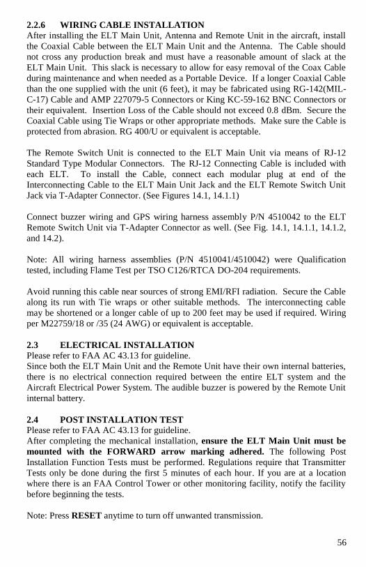
2.2.6 WIRING CABLE INSTALLATION
After installing the ELT Main Unit, Antenna and Remote Unit in the aircraft, install
the Coaxial Cable between the ELT Main Unit and the Antenna. The Cable should
not cross any production break and must have a reasonable amount of slack at the
ELT Main Unit. This slack is necessary to allow for easy removal of the Coax Cable
during maintenance and when needed as a Portable Device. If a longer Coaxial Cable
than the one supplied with the unit (6 feet), it may be fabricated using RG-142(MIL-
C-17) Cable and AMP 227079-5 Connectors or King KC-59-162 BNC Connectors or
their equivalent. Insertion Loss of the Cable should not exceed 0.8 dBm. Secure the
Coaxial Cable using Tie Wraps or other appropriate methods. Make sure the Cable is
protected from abrasion. RG 400/U or equivalent is acceptable.
The Remote Switch Unit is connected to the ELT Main Unit via means of RJ-12
Standard Type Modular Connectors. The RJ-12 Connecting Cable is included with
each ELT. To install the Cable, connect each modular plug at end of the
Interconnecting Cable to the ELT Main Unit Jack and the ELT Remote Switch Unit
Jack via T-Adapter Connector. (See Figures 14.1, 14.1.1)
Connect buzzer wiring and GPS wiring harness assembly P/N 4510042 to the ELT
Remote Switch Unit via T-Adapter Connector as well. (See Fig. 14.1, 14.1.1, 14.1.2,
and 14.2).
Note: All wiring harness assemblies (P/N 4510041/4510042) were Qualification
tested, including Flame Test per TSO C126/RTCA DO-204 requirements.
Avoid running this cable near sources of strong EMI/RFI radiation. Secure the Cable
along its run with Tie wraps or other suitable methods. The interconnecting cable
may be shortened or a longer cable of up to 200 feet may be used if required. Wiring
per M22759/18 or /35 (24 AWG) or equivalent is acceptable.
2.3 ELECTRICAL INSTALLATION
Please refer to FAA AC 43.13 for guideline.
Since both the ELT Main Unit and the Remote Unit have their own internal batteries,
there is no electrical connection required between the entire ELT system and the
Aircraft Electrical Power System. The audible buzzer is powered by the Remote Unit
internal battery.
2.4 POST INSTALLATION TEST
Please refer to FAA AC 43.13 for guideline.
After completing the mechanical installation, ensure the ELT Main Unit must be
mounted with the FORWARD arrow marking adhered. The following Post
Installation Function Tests must be performed. Regulations require that Transmitter
Tests only be done during the first 5 minutes of each hour. If you are at a location
where there is an FAA Control Tower or other monitoring facility, notify the facility
before beginning the tests.
Note: Press RESET anytime to turn off unwanted transmission.
57
2.4.0 QUICK OPERATION CHECK
Note: Refer to Appendix A.1 for Quick Operation Check in sequence order.
2.4.0.1. ELT Main Switch @ ON position: ELT swept Tone must be heard on the
VHF Radio @121.5 MHz. The 2 LEDs flashing (4 sec OFF, 1 second ON),
synchronized with the Buzzer sound (4 sec OFF, 1 sec ON).
2.4.0.2. ELT Main Switch @ ARM position: Both LED Lights and Buzzer must
illuminate and sound for 4 sec, then extinguish.
This is to make sure LED and Buzzer are properly powered.
Note: Press RESET anytime to turn off unwanted transmission.
The ELT will then automatically enter Self test mode. Self test takes 25 sec.
If ELT Self test is passed, No light illuminate, no buzzer sound.
If ELT malfunctions, the LED Lights and buzzer will show 1 flash or 2 flashes, or 3
flashes or 4 flashes etc. Refer to Operation Manual paragraph 2.4.4 for details.
Next, in order to check G Switch, Throw the ELT forward and backward, 2-3 times,
the ELT must activate, ELT swept Tone must be heard on the VHF Radio @121.5
MHz. The 2 LED lights flashing (4 sec OFF, 1 sec ON), synchronized with the
Buzzer sound (4 sec OFF, 1 sec ON).
Next, Press either RESET Button, no ELT swept tone heard on the 121.5 MHz VHF
radio. Both LED Lights and Buzzer must be extinguished.
Next, Press the ON Switch on the Remote Switch Unit, ELT swept Tone must be
heard on the VHF Radio @121.5 MHz. The 2 LED lights flashing (4 sec OFF, 1 sec
ON), synchronized with the Buzzer sound (4 sec OFF, 1 sec ON).
2.4.0.3. For normal operation, leave the ELT Main Switch @ ARM position at all
times.
No ELT swept tone heard on the 121.5 MHz VHF radio. No LED light illuminates,
No buzzer sound.
58
Detail Operation Check:
2.4.1 Monitor 121.5 MHz using the Aircraft Communication Receiver or a
Portable Hand Held Receiver. Important: The Squelch must be turned
all the way UP (Max) to hear he sweep tone on most receivers.
2.4.2 Place the Main Switch on the front of the ELT Main Unit in the “ON”
position and verify that the Audio Sweep Tone can be heard on the COM
Radio. Verify that both the Green ON lights located on the ELT Main Unit
and the ELT Remote Unit are flashing. Verify the buzzer is heard…at a flash
rate and a beeping sound of 1 second ON, 4 seconds OFF.
Place the Main Switch in the “OFF” position. Verify that the Audio Sweep
Tone is ceased and the two Green ON lights are extinguished.
2.4.3 Place the Main Switch on the ELT Main Unit in the “ARM” position.
Wait for 25 seconds.
While seated at the Pilots normal operating position, press the “ON” button
on the Remote Switch Unit. Verify that the Green ON lights is flashing, and
a beeping sound at a rate of 1 second ON, 4 seconds OFF and is readily
visible from the Pilots operating position. Verify that the Audio ELT Sweep
Tone can be heard on the Com Receiver.
Push the “RESET” button on the Remote Unit. Verify that the Audio ELT
Sweep Tone is ceased. Verify the two Green “ON” lights are extinguished
and the buzzer sound is silent.
Note: Always perform the tests within the first 5 minutes of the hour. Notify any
nearby control tower of your intensions, in accordance with AC 43.13-2B, Section
12-22, Note 3. If outside of the US, always follow all local or national regulations for
testing of ELT's.
Warning!
Do not allow test duration to exceed 5-10 seconds. Any time the ELT is activated
it is transmitting a 121.5 MHz distress signal. If the unit operates for
approximately 50 seconds, a "live" 406 MHz satellite distress signal is
transmitted and is considered valid by COSPAS-SARSAT satellite system.
2.4.4. ELT Self Test:
Place the main switch position from "OFF" to "ARM." The buzzer sounds, and the 2
ELT Green “ON” lights shall illuminate for 4 seconds, then extinguish. After 25
seconds, a 406 MHz test signal is transmitted. However it is specially coded as a
"self-test" signal that is ignored by the COSPAS-SARSAT satellites.
Verify that both the ELT Green “ON” lights (located on the ELT Main Unit and the
ELT Remote Unit) must remain extinguished and no buzzer sound after 25 seconds.
Verify Audio ELT Sweep Tone is silent on the Com Receiver.
59
Activate the ELT using applied force. The direction forward force activation is
indicated on the ELT. The AK-451-(AF) (AP) ELT can be activated by using a rapid
forward (throwing) motion coupled by a rapid reversing action. Verify that the ELT
has been activated by use of the Wattmeter, the Airplane’s VHF Radio
Communications Receiver when tuned to 121.5 MHz, or other means (see Note 1).
The ELT must then be reset by pressing either the RESET push button located on the
ELT main unit or the ELT Remote Unit.
Note 1: This is not a measured check. It only indicates that the G-Switch is working.
60
Detail Test Procedure for ELT ID Programming and Self Test:
Turn the main switch from the "OFF" position to the "ARM" position. The
Buzzer sound and the 2 Green ON lights shall illuminate for 4 seconds, then
extinguish. This is to allow coding programming during the next 20 seconds window
and self-test for 1 second thereafter.
The ELT may be ID coding programming during the aforementioned 20
seconds window period. If no programming happened the ELT will then enter the
Self Test Mode for 1 second thereafter.
Self Test takes 25 sec. Self-test results (after 25 seconds,) is:
If the self-test is passed, the Green ON light is steadily extinguished and no buzzer
sound. ELT swept Tone must be silent on the 121.5 MHz VHF Radio.
If the self-test is failed, the Green ON light flashes as defined below:
1 flash: Internal Data stored in Memory at fault.
2 flashes: Distress ID stored in Memory at fault.
3 flashes: Battery voltage is low < Useful Life Battery Voltage setting.
4 flashes: Vcc supplies for F3, F2, or F1 at fault.
5 flashes: F3 RF power level < 33 dBm @ 406.028 MHz
7 flashes: F1/F2 VHF RF power level < 17 dBm @ 121.5/243 MHz.
9 flashes: PLL locked in F3 or F1 or F2 at fault.
Continuous flash: no F3/F2/F1 RF output power, ELT shuts down completely.
Note: The self-test mode that transmits a 406 MHz test code pulse monitors certain
system functions before returning to the ARM mode. The 406 MHz test pulse is
ignored by any satellite that receives the signal, but the ELT uses this output to check
output power and correct frequency.
Self-test is 520 ms long message burst on the 406 MHz signal. Synchronization
pattern is 011 010 000.
Self-test is then 121/243 MHz (VHF) Continuous Wave during 1s.
During Self Test, ELT swept Tone must be silent on the 121.5 MHz VHF Radio.
If No Antenna or No coaxial cable connected, the ELT may or may not 5 flashes.
2.4.5 ELT Self Test Schedule:
We recommend that the ELT be tested every month. Follow the steps outlined above.
Total allowable test is 60 minutes as determined by FAR 91.207 and RTCA DO-204.
After this time has been accumulated a 3-flash error may be presented after the self-
test. The battery must be replaced at this point for the ELT to remain in compliance.
Always follow ELT testing requirements per local or national authorities.
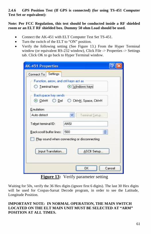
61
2.4.6 GPS Position Test (If GPS is connected) (for using TS-451 Computer
Test Set or equivalent):
Note: Per FCC Regulation, this test should be conducted inside a RF shielded
room or an ELT RF shielded box. Dummy 50 ohm Load should be used.
Connect the AK-451 with ELT Computer Test Set TS-451.
Turn the switch of the ELT to “ON” position.
Verify the following setting (See Figure 13.) From the Hyper Terminal
window (or equivalent RS-232 window), Click File -> Properties -> Settings
tab. Click OK to go back to Hyper Terminal window.
Figure 13: Verify parameter setting
Waiting for 50s, verify the 36 Hex digits (ignore first 6 digits). The last 30 Hex digits
will be used for Cospas-Sarsat Decode program, in order to see the Latitude,
Longitude Position.
IMPORTANT NOTE: IN NORMAL OPERATION, THE MAIN SWITCH
LOCATED ON THE ELT MAIN UNIT MUST BE SELECTED AT “ARM”
POSITION AT ALL TIMES.
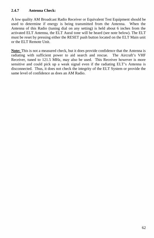
62
2.4.7 Antenna Check:
A low quality AM Broadcast Radio Receiver or Equivalent Test Equipment should be
used to determine if energy is being transmitted from the Antenna. When the
Antenna of this Radio (tuning dial on any setting) is held about 6 inches from the
activated ELT Antenna, the ELT Aural tone will be heard (see note below). The ELT
must be reset by pressing either the RESET push button located on the ELT Main unit
or the ELT Remote Unit.
Note: This is not a measured check, but it does provide confidence that the Antenna is
radiating with sufficient power to aid search and rescue. The Aircraft’s VHF
Receiver, tuned to 121.5 MHz, may also be used. This Receiver however is more
sensitive and could pick up a weak signal even if the radiating ELT’s Antenna is
disconnected. Thus, it does not check the integrity of the ELT System or provide the
same level of confidence as does an AM Radio.
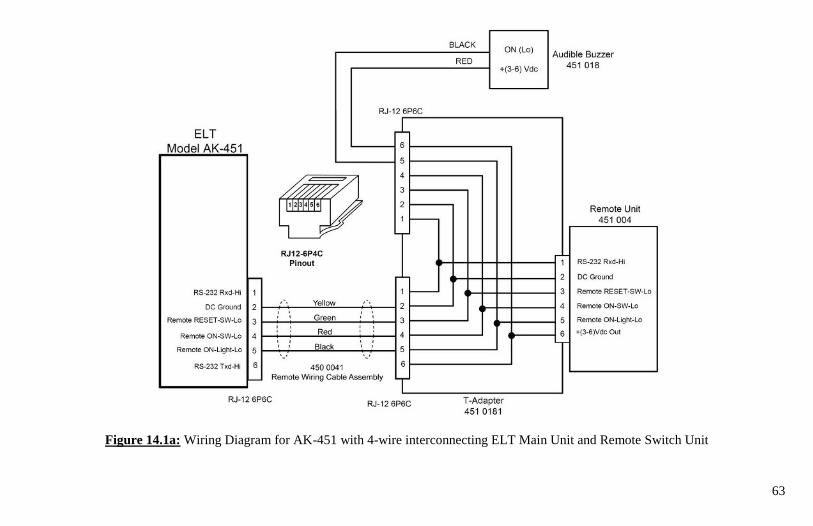
63
Figure 14.1a: Wiring Diagram for AK-451 with 4-wire interconnecting ELT Main Unit and Remote Switch Unit
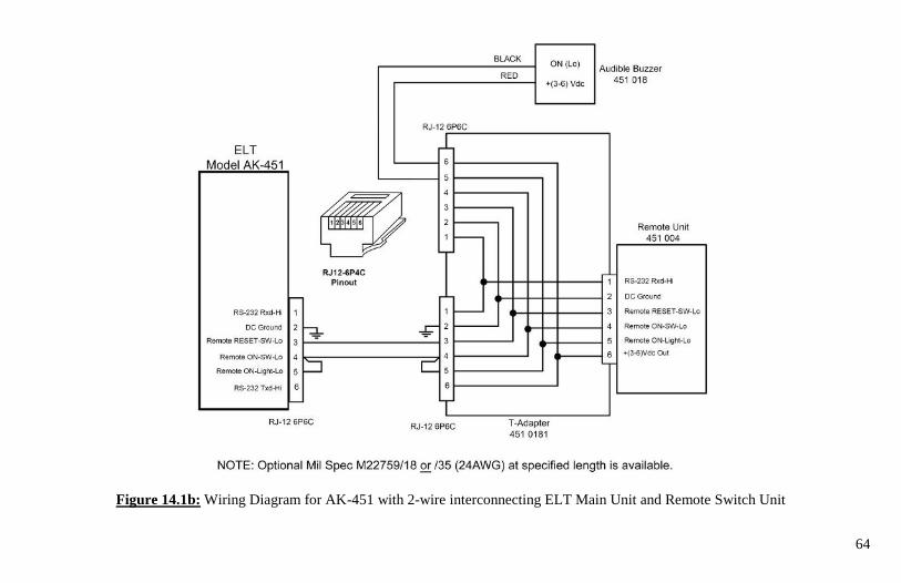
64
Figure 14.1b: Wiring Diagram for AK-451 with 2-wire interconnecting ELT Main Unit and Remote Switch Unit
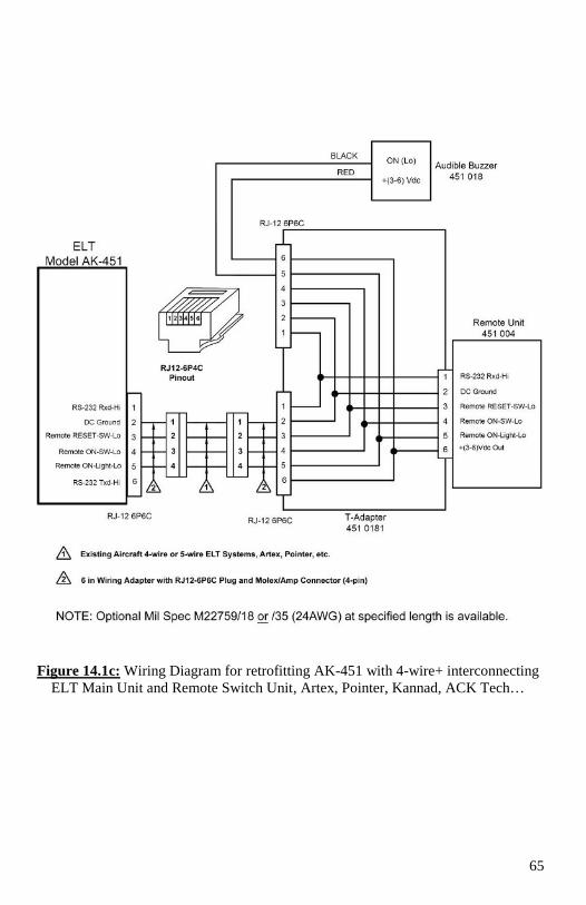
65
Figure 14.1c: Wiring Diagram for retrofitting AK-451 with 4-wire+ interconnecting
ELT Main Unit and Remote Switch Unit, Artex, Pointer, Kannad, ACK Tech…
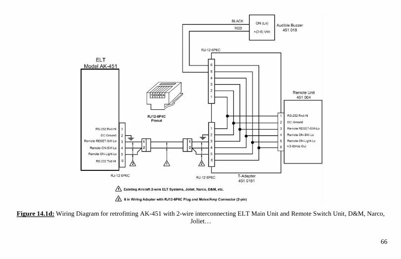
66
Figure 14.1d: Wiring Diagram for retrofitting AK-451 with 2-wire interconnecting ELT Main Unit and Remote Switch Unit, D&M, Narco,
Joliet…
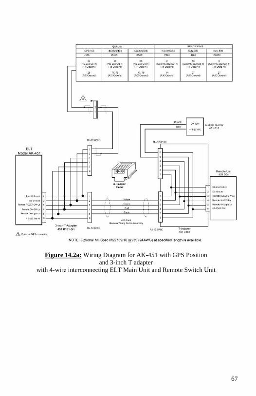
67
Figure 14.2a: Wiring Diagram for AK-451 with GPS Position
and 3-inch T adapter
with 4-wire interconnecting ELT Main Unit and Remote Switch Unit
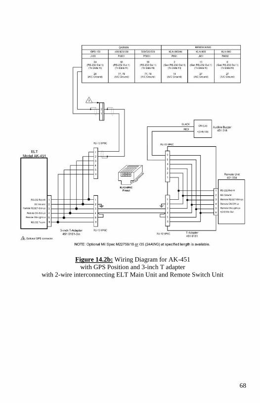
68
Figure 14.2b: Wiring Diagram for AK-451
with GPS Position and 3-inch T adapter
with 2-wire interconnecting ELT Main Unit and Remote Switch Unit
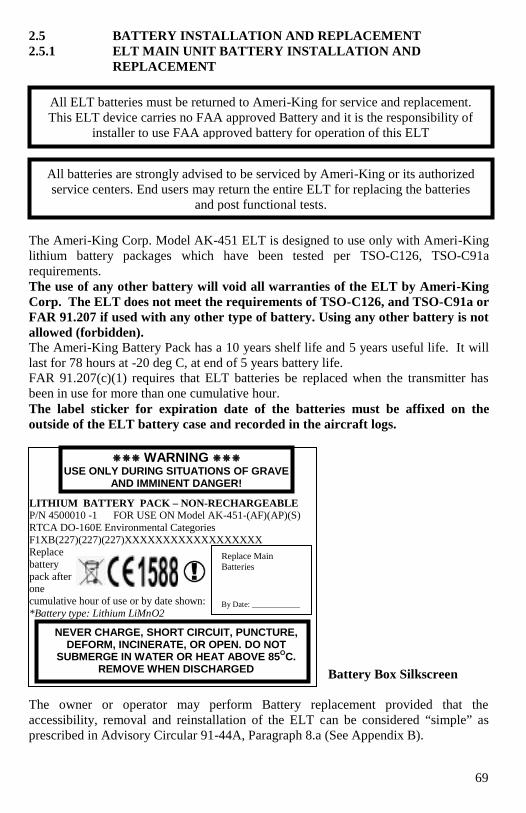
69
2.5 BATTERY INSTALLATION AND REPLACEMENT
2.5.1 ELT MAIN UNIT BATTERY INSTALLATION AND
REPLACEMENT
The Ameri-King Corp. Model AK-451 ELT is designed to use only with Ameri-King
lithium battery packages which have been tested per TSO-C126, TSO-C91a
requirements.
The use of any other battery will void all warranties of the ELT by Ameri-King
Corp. The ELT does not meet the requirements of TSO-C126, and TSO-C91a or
FAR 91.207 if used with any other type of battery. Using any other battery is not
allowed (forbidden).
The Ameri-King Battery Pack has a 10 years shelf life and 5 years useful life. It will
last for 78 hours at -20 deg C, at end of 5 years battery life.
FAR 91.207(c)(1) requires that ELT batteries be replaced when the transmitter has
been in use for more than one cumulative hour.
The label sticker for expiration date of the batteries must be affixed on the
outside of the ELT battery case and recorded in the aircraft logs.
Battery Box Silkscreen
The owner or operator may perform Battery replacement provided that the
accessibility, removal and reinstallation of the ELT can be considered “simple” as
prescribed in Advisory Circular 91-44A, Paragraph 8.a (See Appendix B).
All batteries are strongly advised to be serviced by Ameri-King or its authorized
service centers. End users may return the entire ELT for replacing the batteries
and post functional tests.
LITHIUM BATTERY PACK – NON-RECHARGEABLE P/N 4500010 -1 FOR USE ON Model AK-451-(AF)(AP)(S)
RTCA DO-160E Environmental Categories
F1XB(227)(227)(227)XXXXXXXXXXXXXXXXXX Replace
battery
pack after one
cumulative hour of use or by date shown:
*Battery type: Lithium LiMnO2
Replace Main
Batteries
By Date: ____________
WARNING USE ONLY DURING SITUATIONS OF GRAVE
AND IMMINENT DANGER!
NEVER CHARGE, SHORT CIRCUIT, PUNCTURE, DEFORM, INCINERATE, OR OPEN. DO NOT
SUBMERGE IN WATER OR HEAT ABOVE 85OC.
REMOVE WHEN DISCHARGED
All ELT batteries must be returned to Ameri-King for service and replacement.
This ELT device carries no FAA approved Battery and it is the responsibility of
installer to use FAA approved battery for operation of this ELT
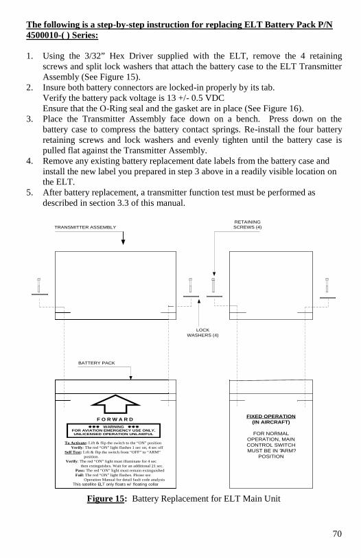
70
The following is a step-by-step instruction for replacing ELT Battery Pack P/N
4500010-( ) Series:
1. Using the 3/32” Hex Driver supplied with the ELT, remove the 4 retaining
screws and split lock washers that attach the battery case to the ELT Transmitter
Assembly (See Figure 15).
2. Insure both battery connectors are locked-in properly by its tab.
Verify the battery pack voltage is 13 +/- 0.5 VDC
Ensure that the O-Ring seal and the gasket are in place (See Figure 16).
3. Place the Transmitter Assembly face down on a bench. Press down on the
battery case to compress the battery contact springs. Re-install the four battery
retaining screws and lock washers and evenly tighten until the battery case is
pulled flat against the Transmitter Assembly.
4. Remove any existing battery replacement date labels from the battery case and
install the new label you prepared in step 3 above in a readily visible location on
the ELT.
5. After battery replacement, a transmitter function test must be performed as
described in section 3.3 of this manual.
FIXED OPERATION
(IN AIRCRAFT)
FOR NORMAL
OPERATION, MAIN
CONTROL SWITCH
MUST BE IN ? ARM?
POSITION
F O R W A R D
To Activate: Lift & flip the switch to the “ON” position
Verify: The red “ON” light flashes 1 sec on, 4 sec off
Self Test: Lift & flip the switch from “OFF” to “ARM”
position.
Verify: The red “ON” light must illuminate for 4 sec
then extinguishes. Wait for an additional 21 sec.
Pass: The red “ON” light must remain extinguished
Fail: The red “ON” light flashes. Please see
Operation Manual for detail fault code analysis
This satellite ELT only floats w/ floating collar
WARNING FOR AVIATION EMERGENCY USE ONLY. UNLICENSED OPERATION UNLAWFUL
TRANSMITTER ASSEMBLY
LOCK
WASHERS (4)
RETAINING
SCREWS (4)
BATTERY PACK
Figure 15: Battery Replacement for ELT Main Unit
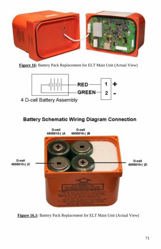
71
Figure 16: Battery Pack Replacement for ELT Main Unit (Actual View)
Figure 16.1: Battery Pack Replacement for ELT Main Unit (Actual View)
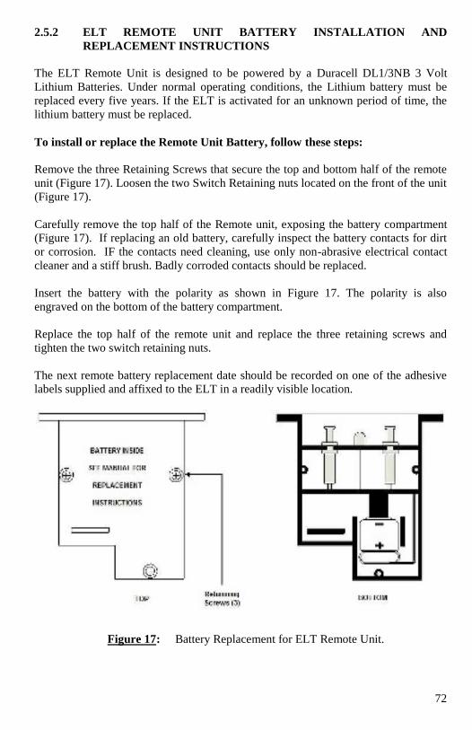
72
2.5.2 ELT REMOTE UNIT BATTERY INSTALLATION AND
REPLACEMENT INSTRUCTIONS
The ELT Remote Unit is designed to be powered by a Duracell DL1/3NB 3 Volt
Lithium Batteries. Under normal operating conditions, the Lithium battery must be
replaced every five years. If the ELT is activated for an unknown period of time, the
lithium battery must be replaced.
To install or replace the Remote Unit Battery, follow these steps:
Remove the three Retaining Screws that secure the top and bottom half of the remote
unit (Figure 17). Loosen the two Switch Retaining nuts located on the front of the unit
(Figure 17).
Carefully remove the top half of the Remote unit, exposing the battery compartment
(Figure 17). If replacing an old battery, carefully inspect the battery contacts for dirt
or corrosion. IF the contacts need cleaning, use only non-abrasive electrical contact
cleaner and a stiff brush. Badly corroded contacts should be replaced.
Insert the battery with the polarity as shown in Figure 17. The polarity is also
engraved on the bottom of the battery compartment.
Replace the top half of the remote unit and replace the three retaining screws and
tighten the two switch retaining nuts.
The next remote battery replacement date should be recorded on one of the adhesive
labels supplied and affixed to the ELT in a readily visible location.
Figure 17: Battery Replacement for ELT Remote Unit.
73
2.6 FAA Form 337
For most installations an FAA Form 337 will be required for FAA registration.
Additional information regarding the completion of FAA Form 337 can be found in
Advisory Circular AC 43.9-1F (Instructions for Completion of FAA Form 337). AC
43-210 (Standardized Procedures for Requesting Field Approval of Data, Major
Alterations and Repairs) provides further guidance. This manual constitutes FAA
approved data as described in AC 43.9-1F, paragraph (h)(2) and AC 43-210, chapter
2, paragraph 201(a)(6) for major alterations. Not all installations are "major;" consult
your local FAA ACO for clarification.
Data used as a basis for approving major repairs or alterations for return to service
must be FAA-approved prior to its use for that purpose and includes: FAR (e.g.,
airworthiness directives), ACs (e.g., AC 43.13-2B under certain circumstances),
TSOs, parts manufacturing approval (PMA), FAA-approved manufacturer’s
instructions, kits and service handbooks, type certificate data sheets and aircraft
specifications. Other forms of approved data would be those approved by a
designated engineering representative (DER), a manufacturer holding a delegation
option authorization (DOA), STCs and, with certain limitations, previous FAA field
approvals.
Supporting data such as stress analyses, test reports, sketches, or photographs should
be submitted with the FAA Form 337. The Ameri-King IM-451 Installation Manual
may be used as a supporting data.
These supporting data will be returned to the applicant by the local FAA district
office since only FAA Form 337 is retained as a part of the aircraft records at
Oklahoma City.
74
SECTION III
OPERATION
3.1 GENERAL
This section describes the operation of the ELT, Emergency Locator Transmitter, mo
tdel AK-451.
The following types are applicable for the model AK-451:
a. Automatic Fixed - Fixed ELT (AF):
See paragraph 1.2.1 (a)
b. Automatic Portable - ELT (AF) (AP) with dual antennas:
See paragraph 1.2.1 (b)
c. Automatic Portable - ELT (AP):
See paragraph 1.2.1 (c)
d. Survival-ELT (S):
See paragraph 1.2.1 (d)
The AK-451 is a "third generation ELT," transmitting on 406.028, 121.5 and 243.0
MHz. The ELT is designed to meet or exceed the requirements of TSO-C126 and
TSO-C91a and the mandatory automatic ELT requirements of FAR Part 91. The ELT
meets the requirements of DOT Aviation Regulations, Section 3, Chapter 3, Part 2.
The ELT automatically activates during a crash and transmits the standard swept tone.
The Green ON lights flashing located on both the ELT Main Unit and the Cockpit
Remote Switch unit and the buzzer sound periodically indicates when the ELT is
activated. The ON switch on the Remote Switch Unit allows you to turn on the ELT
for testing. The RESET Switch on the Remote Switch Unit enables to reset the ELT.
In normal operation, the Main Switch on the ELT Unit must be selected at “ARM"
position.
Note:
You cannot "disarm" or disable the unit from the cockpit; you can only deactivate the
ELT after it has been activated.
The ELT unit is able to withstand extremely harsh environments. Units exactly like
yours have been subjected to numerous 500G shock pulses; 1000 pounds crash
weights and severe penetrator tests, and continue to operate normally. Continued
operation in a temperature range of -20 to +55 degrees Celsius is assured.
75
3.2 OPERATION
The AK-451 ELT, Emergency Locator Transmitter, is a state of the art Micro
controller technology, long lasting, solid state based equipment. It is an extremely
reliable, highest standard of quality, designed to meet TSO-C126 and TSO-C91a
requirements for critical application.
Both ELT main unit and Remote Switch are self-powered by their own internal
batteries. Interface with aircraft electrical power system is not required.
With the main switch, located on the ELT main unit, set at "ARM" position, the AK-
451 ELT is automatically activated upon sensing a change of velocity of 4.5 ± 0.5
Feet/Second, along its longitudinal axis (Automatic Fixed-ELT (AF) Configuration).
It is also designed to be removed from the aircraft and used as a personal locating
device when it is necessary to leave the scene of the accident (Automatic Portable
ELT (AP) Configuration) and survival ELT(s) configuration.
In the event of a crash, the AK-451 activates automatically, and transmits the standard
swept tone on 243/121.5 MHz lasting until battery power is gone. This 243/121.5
MHz signal is mainly used to pinpoint the beacon during search and rescue
operations.
For the first 24 hours of operations, a 406 MHz signal is transmitted at 50-second
intervals. This transmission lasts 520 ms and contains identification data programmed
into the beacon and is received by COSPAS-SARSAT satellites. The aircraft
GPS/NAV latitude/longitude data position will also be transmitted (if GPS/NAV is
connected with the ELT). The transmitted data is referenced in a database (maintained
by the national authority responsible for ELT registration) and used to identify the
beacon and owner.
Accuracy:
Doppler positioning is employed using both 121.5 MHz and 406 MHz signals.
Position accuracy of the 121.5 MHz signal is within an area of approximately 15-20
km radius about the transmitter. Due to the better signal integrity of the 406 MHz, its
location accuracy is within about a 1-2 km radius. If the GPS/NAV position data is
transmitted, the accuracy of the AK-451 will narrow to 22 meters (typically).
3.3 TRANSMITTER FUNTIONAL TEST
The ELT should be tested every month.
76
WARNING
Do not allow test duration to exceed 5-10 seconds. A false alarm may be
generated.
Any time the ELT is activated, it is transmitting a 121.5 MHz and 243.0 MHz
distress signal. If the ELT operates for approximately 50 seconds, a “live” 406
MHz distress signal is transmitted and is considered valid by the Cospas-Sarsat
satellite system.
Any time that the ELT Main Switch is lifted and flipped from “OFF” to “ARM”,
a 406 MHz self test signal is transmitted (after 25 seconds), however it is
specially coded as a “self test” signal that is ignored by the COSPAS-SARSAT
satellites.
Note: Press RESET anytime to turn off unwanted transmission.
3.3.0 QUICK OPERATION CHECK
Note: Refer to Appendix A.1 for Quick Operation Check in sequence order.
3.3.0.1 ELT Main Switch @ ON position: ELT swept Tone must be heard on the
VHF Radio @121.5 MHz. The 2 LED lights flashing (4 sec OFF, 1 sec ON),
synchronized with the Buzzer sound (4 sec OFF, 1 sec ON).
3.3.0.2 ELT Main Switch @ ARM position: Both LED Lights and Buzzer must
illuminate and sound for 4 sec, then extinguish.
This is to make sure LED and Buzzer are properly powered.
Note: Press RESET anytime to turn off unwanted transmission.
The ELT will then automatically enter Self test mode. Self test takes 25 sec.
If ELT Self test is passed, No light illuminate, no buzzer sound.
If ELT malfunctions, the LED Lights and buzzer will show 1 flash, 2 flashes, 3
flashes, or 4 flashes etc. Refer to Operation Manual of trouble shooting error flashes
meaning.
Next, in order to check G Switch, Throw the ELT forward and backward, 2-3 times,
the ELT must activate, ELT swept Tone must be heard on the VHF Radio @121.5
MHz. The 2 LED lights flashing (4 sec OFF, 1 sec ON), synchronized with the
Buzzer sound (4 sec OFF, 1 sec ON).
Next, Press either RESET Button, no ELT swept tone heard on the 121.5 MHz VHF
radio. Both LED Lights and Buzzer must be extinguished.
Next, Press the ON Switch on the Remote Switch Unit, ELT swept Tone must be
heard on the VHF Radio @121.5 MHz. The 2 LED lights flashing (4 sec OFF, 1 sec
ON), synchronized with the Buzzer sound (4 sec OFF, 1 sec ON).
3.3.0.3 For normal operation, leave the ELT Main Switch @ ARM position at all
times.
No ELT swept tone heard on the 121.5 MHz VHF radio. No LED light illuminates.
No buzzer sound.
77
Detailed Operation Check:
3.3.1 Main Switch ON/OFF/ARM Operation:
In normal operation, the Main Switch, located on the ELT main unit, must be in the
"ARM" position. In the event of a crash, an acceleration activated crash censor (G-
switch) turns the ELT 'on' automatically when the ELT experiences a change in
velocity (or deceleration) of 4.5 fps ± 0.5 fps. Activation is also accomplished by
means of the cockpit mounted remote control unit or the "ON" switch on the ELT
main unit. To reset the ELT press either "RESET" switch on the remote control panel
or on the main unit.
The ELT has an "OFF" position. This allows the beacon to be handled or shipped
without 'nuisance' activation. Care should be taken when transporting or shipping the
ELT not to move the switch or to allow packing material to become lodged such as to
toggle the switch.
Main switch, alternate positions:
"ON:" ELT transmits immediately. Both Green ON lights on the main unit and
remote switch unit flash and the buzzer sound, at rate of 1 second ON, 4 seconds
OFF. The ELT swept Tone must be heard on the 121.5 MHz VHF Radio.
"OFF:" The ELT is turned off.
"ARM:" ELT self-test is confirmed after 24 seconds. If the self-test is passed, the
2 Green ON lights and the buzzer sound must be extinguished. The ELT swept
Tone must be silent on the 121.5 MHz VHF Radio.
The ELT system is then in the "ARM" mode.
3.3.2 Transmitter ID Programming and Self-Test:
Turn the main switch from the "OFF" position to the "ARM" position. The
Buzzer sound and the 2 Green ON lights shall illuminate for 4 seconds, then
extinguish. This is to allow coding programming during the next 20 seconds window
and self-test for 1 second thereafter.
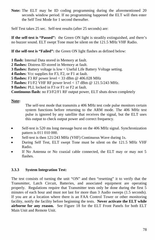
78
Note: The ELT may be ID coding programming during the aforementioned 20
seconds window period. If no programming happened the ELT will then enter
the Self Test Mode for 1 second thereafter.
Self Test takes 25 sec. Self-test results (after 25 seconds) are:
If the self-test is “Passed”: the Green ON light is steadily extinguished, and there’s
no buzzer sound. ELT swept Tone must be silent on the 121.5 MHz VHF Radio.
If the self-test is “Failed”: the Green ON light flashes as defined below:
1 flash: Internal Data stored in Memory at fault.
2 flashes: Distress ID stored in Memory at fault.
3 flashes: Battery voltage is low < Useful Life Battery Voltage setting.
4 flashes: Vcc supplies for F3, F2, or F1 at fault.
5 flashes: F3 RF power level < 33 dBm @ 406.028 MHz
7 flashes: F1/F2 VHF RF power level < 17 dBm @ 121.5/243 MHz.
9 flashes: PLL locked in F3 or F1 or F2 at fault.
Continuous flash: no F3/F2/F1 RF output power, ELT shuts down completely
Note: The self-test mode that transmits a 406 MHz test code pulse monitors certain
system functions before returning to the ARM mode. The 406 MHz test
pulse is ignored by any satellite that receives the signal, but the ELT uses
this output to check output power and correct frequency.
Self-test is 520 ms long message burst on the 406 MHz signal. Synchronization
pattern is 011 010 000.
Self-test is then 121/243 MHz (VHF) Continuous Wave during 1s.
During Self Test, ELT swept Tone must be silent on the 121.5 MHz VHF
Radio.
If No Antenna or No coaxial cable connected, the ELT may or may not 5
flashes.
3.3.3 System Integration Test:
The test consists of turning the unit “ON” and then “resetting” it to verify that the
Transmitter, Latch Circuit, Batteries, and associated equipment are operating
properly. Regulations require that Transmitter tests only be done during the first 5
minutes of each hour and must not last for more than 3 Audio sweeps (1.5 seconds).
If you are at a location where there is an FAA Control Tower or other monitoring
facility, notify the facility before beginning the tests. Never activate the ELT while
airborne for any reason. See Figure 18 for the ELT Front Panels for both ELT
Main Unit and Remote Unit.
79
Figure 18: ELT Front Panels-Main Unit and Remote Unit.
80
3.3.3.1 Monitor 121.5 MHz using the Aircraft Com Receiver or Portable Hand Held
Receiver. Turn the Squelch all the way up or ON.
3.3.3.2 Ensure that the main switch on the ELT is on “ARM” position.
Push the “ON” button on the Cockpit Remote Switch Unit. Verify that both the
Green ON lights, located on the Main Unit and the Cockpit Remote Switch Unit,
are flashing. Verify the Buzzer sound periodically. Verify the ELT audio sweep
tone can be heard on the Com Receiver.
Push the RESET button on the Remote Switch unit. Verify that the two Green
ON lights are extinguished. Verify the Buzzer sound ceased. Verify the ELT
audio sweep tone ceased.
G Switch Check: Activate the G switch by using a rapid forward (throwing) motion
coupled by a rapid reversing action. Verify that the ELT has been activated by use of
the Wattmeter, the Airplane’s VHF Radio Communications Receiver when tuned to
121.5 MHz, or other means (see Note 1). The ELT must then be reset by pressing
either the RESET push button located on the ELT main unit or the ELT Remote Unit.
Note 1: This is not a measured check. It only indicates that the G-Switch is working.
Note:
In normal configuration, the main switch on the ELT Main Unit must be selected to
the “ARM” position. Whenever both the Green ON lights (located on the Main Unit
and the Remote Switch Unit) flash and the Buzzer sound periodically, they indicate
the ELT is transmitting.
If the ELT be accidentally activated by turbulence, hard landing, etc., or if this occur
under any conditions other than an accident requiring immediate assistance, pressing
the RESET button on the Remote Switch Unit.
If the Aircraft is on the ground and the RESET button on the Remote Unit does not
cause the Green ON light to extinguish, the RESET button on the Main Unit should
be pressed. If airborne and the RESET button on the Remote unit does not cause the
Green ON LIGHT to extinguish, the main switch on the ELT should be set to the OFF
position, if the ELT is accessible.
If the ELT is not accessible in flight, you should land at the nearest suitable airport
and set the Main Switch to the OFF position. In either case, the unit should be
inspected by qualified facility as soon as possible.
The Aircraft may be operated with the ELT removed for inspection or repair subject
to the conditions of FAR 91.207.
In the event of an accident, Push the “ON” button on the Cockpit Remote Switch
Unit. The ELT will be ON immediately.
81
In the event of an accident, ensure that the External Aircraft Antenna has no damage.
Important:
If the ELT is accessible after the accident, place the Main Switch in the ON
position and monitor it on 121.5 MHz for proper operation if possible. If the
Antenna is broken off of the Aircraft, the ELT Unit should be removed and the
portable antenna to be used. If the ELT Unit is to remain at the Aircraft site, it should
be placed on a large metallic portion of the airframe with its Antenna pointing
skyward. The Green ON lights should be flashing after the accident.
If the ELT is to be taken along as the Portable Unit when leaving the scene of the
accident, place the Main switch in the ON position and keep the Antenna vertically
oriented as much as possible. The ELT Green ON light should be flashing.
3.3.4 Green ON lights, Buzzer sound, and Antenna check:
3.3.4.1 Green ON Lights and Buzzer Sound Functions:
Green ON lights, located on the ELT main unit and remote switch unit:
In ON mode: Green ON LED flashes continuously (1 second ON, 4 second
OFF) and the Buzzer sound periodically. The ELT swept Tone must be heard on the
121.5 MHz VHF Radio. This is to indicate that the ELT has been manually activated.
In ARM mode: Green ON light flashes continuously (1 second ON, 4 second
OFF) and the Buzzer sound periodically. ELT swept Tone is heard on the 121.5 MHz
VHF Radio. This is to indicate that the ELT has been auto activated by the G switch.
3.3.4.2 Antenna Check: A low quality AM Broadcast Radio Receiver or
Equivalent Test Equipment should be used to determine if energy is being transmitted
from the Antenna. When the Antenna of this Radio (tuning dial on any setting) is
held about 6 inches from the activated ELT Antenna, the ELT Aural tone will be
heard (see note below). The ELT must be reset by pressing either the RESET push
button located on the ELT Main unit or the ELT Remote Unit.
Note: This is not a measured check, but it does provide confidence that the Antenna is
radiating with sufficient power to aid search and rescue. The Aircraft’s VHF
Receiver, tuned to 121.5 MHz, may also be used. This Receiver however is more
sensitive and could pick up a weak signal even if the radiating ELT’s Antenna is
disconnected. Thus, it does not check the integrity of the ELT System or provide the
same level of confidence as does an AM Radio.
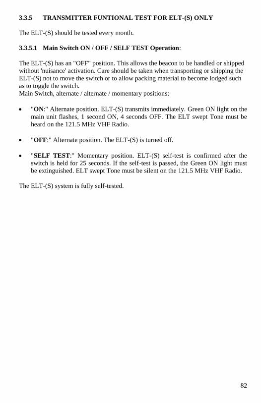
82
3.3.5 TRANSMITTER FUNTIONAL TEST FOR ELT-(S) ONLY
The ELT-(S) should be tested every month.
3.3.5.1 Main Switch ON / OFF / SELF TEST Operation:
The ELT-(S) has an "OFF" position. This allows the beacon to be handled or shipped
without 'nuisance' activation. Care should be taken when transporting or shipping the
ELT-(S) not to move the switch or to allow packing material to become lodged such
as to toggle the switch.
Main Switch, alternate / alternate / momentary positions:
"ON:" Alternate position. ELT-(S) transmits immediately. Green ON light on the
main unit flashes, 1 second ON, 4 seconds OFF. The ELT swept Tone must be
heard on the 121.5 MHz VHF Radio.
"OFF:" Alternate position. The ELT-(S) is turned off.
"SELF TEST:" Momentary position. ELT-(S) self-test is confirmed after the
switch is held for 25 seconds. If the self-test is passed, the Green ON light must
be extinguished. ELT swept Tone must be silent on the 121.5 MHz VHF Radio.
The ELT-(S) system is fully self-tested.

83
3.3.5.2 Transmitter Self-Test:
Turn and hold the main switch, from the "OFF" position to the "SELF TEST"
position. The Green ON light shall illuminate for 4 seconds then extinguish. This is to
allow coding programming during next 20 seconds window and self-test for 1 second
thereafter.
The ELT-(S) may be coding programming during the aforementioned 20 seconds
window period. If no programming happened the ELT will then enter the Self Test
Mode for 1 second thereafter.
Self-test results after (4+20+1) =25 seconds, is:
If the self-test is passed, the Green ON LIGHT is steadily extinguished. ELT swept
Tone must be silent on the 121.5 MHz VHF Radio.
If the self-test is failed, the Green ON LIGHT flashes as shown below:
1 flash: Internal Data stored in Memory at fault.
2 flashes: Distress ID stored in Memory at fault.
3 flashes: Battery voltage is low < Useful Life Battery Voltage setting.
4 flashes: Vcc supplies for F3, F2, or F1 at fault.
5 flashes: F3 RF power level < 33 dBm @ 406.028 MHz
7 flashes: F1/F2 VHF RF power level < 17 dBm @ 121.5/243 MHz.
9 flashes: PLL locked in F3 or F1 or F2 at fault.
Continuous flash: no F3/F2/F1 RF output power, ELT shuts down completely.
Note: The self-test mode that transmits a 406 MHz test code pulse monitors certain system
functions before returning to the SELF TEST mode. The 406 MHz test pulse is
ignored by any satellite that receives the signal, but the ELT-(S) uses this output to
check output power and correct frequency.
Self-test is 520 ms long message burst on the 406 MHz signal. Synchronization
pattern is 011 010 000.
Self-test is then 121/243 MHz (VHF) Continuous Wave during 1s.
During Self Test, the ELT swept Tone is silent on the 121.5 MHz VHF Radio.
The ELT-(S) may accept GPS position input by connecting the external GPS to the
Remote connector
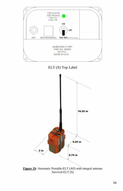
84
ELT-(S) Top Label
Figure 19: Automatic Portable-ELT (AP) with integral antenna
Survival-ELT (S)
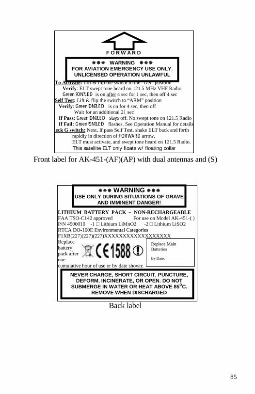
85
Front label
Front label for AK-451-(AF)(AP) with dual antennas and (S)
Back label
F O R W A R D
To Activate: Lift & flip the switch to the “ON” position Verify: ELT swept tone heard on 121.5 MHz VHF Radio
Green ? ON? LED is on after 4 sec for 1 sec, then off 4 sec
Self Test: Lift & flip the switch to “ARM” position
Verify: Green ?ON? LED is on for 4 sec, then off Wait for an additional 21 sec
If Pass: Green ?ON? LED stays off. No swept tone on 121.5 Radio
If Fail: Green ?ON? LED flashes. See Operation Manual for details
Check G switch: Next, If pass Self Test, shake ELT back and forth
rapidly in direction of FORWARD arrow. ELT must activate, and swept tone heard on 121.5 Radio.
This satellite ELT only floats w/ floating collar
WARNING FOR AVIATION EMERGENCY USE ONLY. UNLICENSED OPERATION UNLAWFUL
LITHIUM BATTERY PACK – NON-RECHARGEABLE FAA TSO-C142 approved For use on Model AK-451-( ) P/N 4500010 -1 □ Lithium LiMnO2 -2 □ Lithium LiSO2
RTCA DO-160E Environmental Categories
F1XB(227)(227)(227)XXXXXXXXXXXXXXXXXX Replace
battery
pack after one
cumulative hour of use or by date shown:
Replace Main
Batteries
By Date: ____________
WARNING USE ONLY DURING SITUATIONS OF GRAVE
AND IMMINENT DANGER!
NEVER CHARGE, SHORT CIRCUIT, PUNCTURE, DEFORM, INCINERATE, OR OPEN. DO NOT
SUBMERGE IN WATER OR HEAT ABOVE 85OC.
REMOVE WHEN DISCHARGED
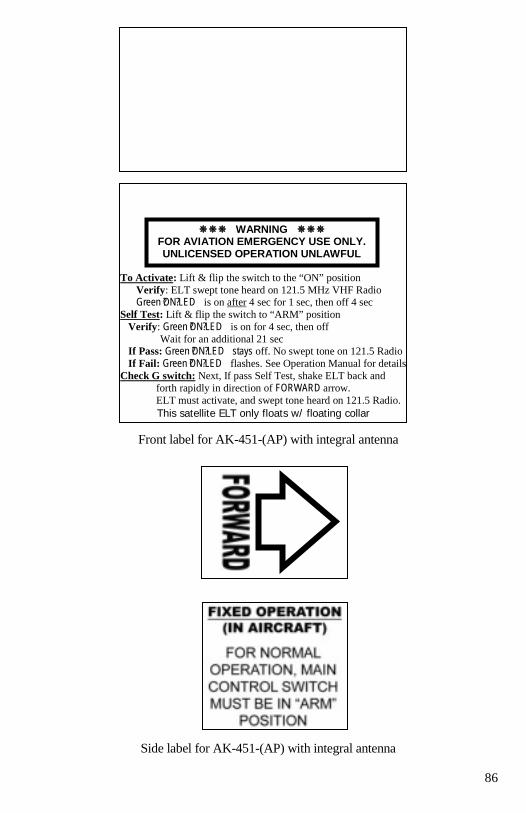
86
Front label for AK-451-(AP) with integral antenna
Side label for AK-451-(AP) with integral antenna
To Activate: Lift & flip the switch to the “ON” position
Verify: ELT swept tone heard on 121.5 MHz VHF Radio Green ?ON? LED is on after 4 sec for 1 sec, then off 4 sec
Self Test: Lift & flip the switch to “ARM” position
Verify: Green ?ON? LED is on for 4 sec, then off
Wait for an additional 21 sec If Pass: Green ?ON? LED stays off. No swept tone on 121.5 Radio
If Fail: Green ?ON? LED flashes. See Operation Manual for details
Check G switch: Next, If pass Self Test, shake ELT back and
forth rapidly in direction of FORWARD arrow.
ELT must activate, and swept tone heard on 121.5 Radio.
This satellite ELT only floats w/ floating collar
WARNING FOR AVIATION EMERGENCY USE ONLY. UNLICENSED OPERATION UNLAWFUL
87
3.4 PERIODIC MAINTENANCE (INSTRUCTIONS FOR CONTINUED
AIRWORTHINESS):
REFERENCES: FAR Part 91.207, Part 43 Appendix D (i).
FAR Part 91.207 Paragraph (d)
FAR Part 91.407
Refer to Appendix B for Maintenance Check List with Compliance Cross
References.
PURPOSE: To insure continued reliability of your ELT, it must be inspected for damage and wear
which could be caused by age, exposed elements, vibrations, etc. Even the best
designed equipment, if not properly maintained and cared for, will eventually fail.
IMPORTANT NOTES: The following inspections must be performed, a minimum of one time every year:
3.4.1 Secure Inspection: Inspect the ELT Main Unit and Mounting Tray to insure
all fasteners and mechanical assemblies are secure.
3.4.2 Corrosion Inspection for Coaxial Cable: Inspect the Coaxial Cable
connecting the ELT Main Unit to the Antenna for cuts or abrasions on its outer jacket.
Disconnect the BNC connectors on each end. Examine both the BNC connectors and
the mating plug on the Antenna and the ELT Main Unit for any signs of corrosion.
3.4.3 Corrosion Inspection for Remote Wiring Modular Cable: Inspect the
Remote Wiring Modular Cable, connecting the ELT Main Unit to the Remote Unit of
signs of wear or abrasion on its outer jacket. Remove the Modular Connecting Cable
and inspect and jack and plug assembly for corrosion.
3.4.4 Battery Expiration Date Check: Check the expiration date of the ELT
Main Unit and the Remote Unit Batteries. Replace if necessary.
3.4.5 Battery Leakage Check: Remove the Battery Case and inspect the Battery
Compartment for signs of corrosion or battery leakage. If any battery leakage is
present, all batteries must be replaced. The Battery useful life is 5 years.
3.4.6 Operational Test: After completing the above inspections, a Functional Test
as described in Paragraph 3.3 must be performed to verify proper operation.
3.4.7.1 G-Switch Check: Ensure that the Main Switch on the ELT main unit must
be selected at “ARM: position at all times. Activate the ELT using applied force. The
direction for mounting and force activation is indicated on the ELT. The AK-451-
(AF)(AP) ELT can be activated by using a rapid forward (throwing) motion coupled
by a rapid reversing action. Verify that the ELT has been activated by use of the
Wattmeter, the Airplane’s VHF Radio Communications Receiver when tuned to
121.5 MHz, or other means (see Note 1). The ELT must then be reset by pressing
either the RESET push button located on the ELT main unit or the ELT Remote Unit.
88
Note 1: This is not a measured check. It only indicates that the G-Switch is working.
3.4.7.2 Antenna Check: A low quality AM Broadcast Radio Receiver or
Equivalent Test Equipment should be used to determine if energy is being transmitted
from the Antenna. When the Antenna of this Radio (tuning dial on any setting) is
held about 6 inches from the activated ELT Antenna, the ELT Aural tone will be
heard (see notes 2 and 3). The ELT must be reset by pressing either the RESET push
button located on the ELT Main unit or the ELT Remote Unit.
Note 2: This is not a measured check, but it does provide confidence that the Antenna is
radiating with sufficient power to aid search and rescue. The Aircraft’s VHF
Receiver, tuned to 121.5 MHz, may also be used. This Receiver however is more
sensitive and could pick up a weak signal even if the radiating ELT’s Antenna is
disconnected. Thus, it does not check the integrity of the ELT System or provide the
same level of confidence as does an AM Radio.
Note 3:
Because the ELT radiates on the emergency frequency, the Federal Communications
Commission allows these tests to be conducted only within the first 5 minutes after
any hour.
IMPORTANT NOTE: IN NORMAL CONFIGURATION, THE MAIN SWITCH, LOCATED ON THE
ELT MAIN UNIT, MUST BE SELECTED AT “ARM” POSITION AT ALL TIMES.
3.4.8 Verification of Digital Message
Note:
This test is not mandatory per FAR 91.207(d) however Ameri-King strongly
recommends that it be performed as part of periodic maintenance, at least every
year.
Verify the 406 MHz digital message using a Computer Test Set or equivalent, capable
of receiving and decoding the message. Ameri-King suggests the Ameri-King ELT
Computer Test Set P/N TS-451. Contact your local Ameri-King dealer for availability
of the Computer Test Set or call Ameri-King. Follow instructions provided with the
computer test set.
The AMERI-KING AK-451 has a self-test feature, which is encoded such that it will
be ignored by the SAR satellite system. This 15-digit number is used to register the
ELT with the appropriate 406 MHz ELT registration authority. In the US, the
National Oceanic and Atmospheric Administration (NOAA) maintain the database of
registered ELT's.
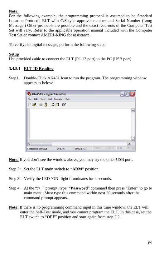
89
Note: For the following example, the programming protocol is assumed to be Standard
Location Protocol, ELT with C/S type approval number and Serial Number (Long
Message.) Other protocols are possible and the exact read-outs of the Computer Test
Set will vary. Refer to the applicable operation manual included with the Computer
Test Set or contact AMERI-KING for assistance.
To verify the digital message, perform the following steps:
Setup
Use provided cable to connect the ELT (RJ-12 port) to the PC (USB port)
3.4.8.1 ELT ID Reading
Step1: Double-Click AK451 Icon to run the program. The programming window
appears as below:
Note: If you don’t see the window above, you may try the other USB port.
Step 2: Set the ELT main switch to “ARM” position.
Step 3: Verify the LED ‘ON’ light illuminates for 4 seconds.
Step 4: At the “:>_” prompt, type: “Password” command then press “Enter” to go to
main menu. Must type this command within next 20 seconds after the
command prompt appears.
Note: If there is no programming command input in this time window, the ELT will
enter the Self-Test mode, and you cannot program the ELT. In this case, set the
ELT switch to “OFF” position and start again from step 2.2.
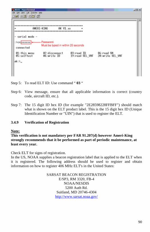
90
Step 5: To read ELT ID: Use command “ 03 “
Step 6: View message, ensure that all applicable information is correct (country
code, aircraft ID, etc.).
Step 7: The 15 digit ID hex ID (for example "2E28598228FFBFF") should match
what is shown on the ELT product label. This is the 15 digit hex ID (Unique
Identification Number or "UIN") that is used to register the ELT.
3.4.9 Verification of Registration
Note:
This verification is not mandatory per FAR 91.207(d) however Ameri-King
strongly recommends that it be performed as part of periodic maintenance, at
least every year.
Check ELT for signs of registration.
In the US, NOAA supplies a beacon registration label that is applied to the ELT when
it is registered. The following address should be used to register and obtain
information on how to register 406 MHz ELT's in the United States:
SARSAT BEACON REGISTRATION
E/SP3, RM 3320, FB-4
NOAA/NESDIS
5200 Auth Rd.
Suitland, MD 20746-4304
http://www.sarsat.noaa.gov/
91
The Ameri-King website also contains information on registering beacons in other
countries
http://www.Ameri-King.com
NOTICE: FOR ELTS THAT HAVE A COUNTRY OF REGISTRATION OTHER
THAN THE USA, PLEASE CONTACT THE APPROPRIATE CIVIL
AVIATION AUTHORITY IN THAT COUNTRY FOR GUIDELINES
AND DOCUMENTATION NEEDED TO ASSURE PROPER
REGISTRATION
Logbook Entry:
Enter the date the test technician's initials and whether the ELT passed or failed into
the aircraft's logbook.
3.4.10 Verification of ELT/GPS interface (if equipped)
Note: This test is not mandatory per FAR 91.207(d); however, Ameri-King
strongly recommends that it be performed as part of periodic
maintenance, at least every year.
3.4.10.1 ELT to GPS Interface Information
For details on the installation and use of the ELT Computer Test Set TS-451, please
contact Ameri-King Corporation to request the brochures and Operation Manual for
the ELT Computer Test Set.
When used with ELT's that are programmed for Standard Location 24 bit protocol,
the ELT to be program itself to the aircraft's 24 bit address. This feature will allow the
ELT to be transferred between aircraft. This makes maintenance of the ELT a simple
matter of replacing the ELT. Note: There is no electronic connection between TCAS
or Mode S systems and the ELT, only the ID number is common.
The AK-451 receives position data (longitude and latitude) from the aircraft's on-
board GPS system. The ELT may be programmed with the aircraft's 24 bit address.
When used with ELT's that are programmed for long message 24 bit protocol, which
is set up to match the 24 bit address parity of the Mode S surveillance and
communications system switch block.
Note: There is no electronic connection between TCAS or Mode S systems and the
ELT, only the ID number is common. This feature was implemented in the ELT with
fleet operators in mind. ELT's are programmed with either a serialized or 24 bit
protocol. The ELT transmits position data as part of the 406.025 MHz distress
message.
In the event of a crash, the ELT will transmit the converted position information from
the navigation system, such as the GPS flight management computer, loran, etc.
Geostationary satellites constantly monitor the 406.025 MHz transmissions. The crash
site is instantly known due to the aircraft's navigation system position data
92
communication with the ELT. Without the position data being transmitted, it is
necessary for the polar orbiting satellites to pass overhead, using Doppler Shift
technology to determine position. In a worst case scenario this could be a 3 to 4 hour
wait for a polar orbiting satellite to pass over. In addition, the accuracy of the position
fix is much better i.e. 22 meters (with GPS/Nav Position data) versus 1 to 2
kilometers for the standard 406.028 MHz system (without GPS/NAV Position data).
The ELT accept Aviation RS-232 data bus formats. By reprogramming the ELT with
the aircraft's 24 bit identification or serialized (long message format), this facilitates
moving the ELT from one aircraft to another when performing routine maintenance,
etc.
WARNING: The programming and labeling of the ELT must match the aircraft it is
installed in. The product label will have to be re-marked to reflect the
new programming and/or country of registry if a 24-Bit address long
message protocol ELT is reprogrammed.
Re-registration may not be required if the contact information does not change;
however, contact your local civil aviation or beacon registration authority when in
doubt.
Both serialized long message and 24-Bit address long message, re-programmed
ELT, that is moved to another aircraft, shall need to be re-registered Online or
by Mail.
The user must specify 24-bit long message programming when ordering the ELT.
Changing the programming protocol of the ELT can only be done at Ameri-King or
an authorized Ameri-King Repair Station.
3.4.10.2. ELT/GPS Interface Communication Formats
The only Aviation RS-232 format which is supported is limited to the following
conditions: Baud Rate (fixed): 9600
Parity: None
Data Bits: 8
Stop Bits: 1
In addition the RS-232 format must have a Start of Text (STX): an "A" identifier for
latitude; a "B" identifier for longitude and END of Text (ETX). The format expects
carriage returns but will not operate if there are line feeds.
The following manufacturer's navigation systems are known to interface with the AK-
451:
GARMIN INTERNATIONAL INC.:
• All Series: 150/ 250/ 400/420/430/ 500/520/530
HONEYWELL BENDIX-KING INC.:
• KLN 88, KLN89, KLN89B, KLN 90, KLN90B, KLN94, KLN900.
ARNAV SYSTEMS INC.:
• R50, R50i, STAR 5000, FMS 5000, MFD (Multi-Functional Display).
93
II MORROW:
• FLYBUDDY, 2001 NMS
TRIMBLE NAV INC.:
• NAV 1000, NAV 2000, TNL 2100, and TNL3100. The following Trimble systems
all require a RS-422 to RS-232 adapter: NAV 3000, TNL 1000, TNL 2000, TNL
2000A, TNL 3000, 2000 APPROACH, 2000 APPROACH PLUS, 2101
APPROACH, 2101 APPROACH PLUS, 2101 I/O APPROACH, 2101 I/O
APPROACH PLUS.
For other equipment models contact that equipment manufacturer to determine if their
equipment supports the Aviation RS-232 format specified above.
3.4.10.3 ELT/FMC Interface and Checkout Process
All installation processes and interconnections to navigation systems should adhere to
the guidelines set forth in the FAA Advisory Circulars 43.13-2B, 20-130A and 20-
138, or later revisions of these documents. It is very important that the Global
Positioning System/Flight Management Computer (GPS/FMC) manufacturer's
installation instructions be consulted regarding installation details that may be specific
to the GPS/FMC. Refer to the installation instructions specific to the GPS/FMC that
you are connecting the ELT for specific instructions.
For all testing of the 406 MHz output, only the "test message" that is transmitted at
turn off is required to verify the ELT and ELT/GPS Interface function.
Note: It is extremely important that the ELT/GPS Interface installation not be in
conflict with the GPS/FMC manufacturer's installation instructions in order to avoid
an installation that may degrade the GPS/FMC performance. As a result, the Post
Installation checkout in the GPS/
FMC Installation Manual may be followed after installing the ELT.
3.4.10.4 24-Bit Address Installation Test (mandatory for Installations
reprogramming by Ameri-King’s authorized dealer):
Verify the 24 Bit Address by using the ELT Computer Test Set TS-451 or equivalent.
The 15 digit hex code shall be extracted by using the Computer Test Set or
equivalent. Realize that the AK-451 transmits a 406 MHz test message, which is
encoded such that it will be ignored by the SAR satellite system. This 15-digit
number is used to register the ELT with the appropriate 406 MHz ELT registration
authority. In the US, the National Oceanic and Atmospheric Administration (NOAA)
maintains the database of registered ELT's.
Note: Although a typical 15 digit hex code can contain position data, the 15-digit
ID used for registration purposes shall contain the "default' value of no
position data instead (this is indicated by the last 5 digits of the 15 digit
hex code being "FFBFF").
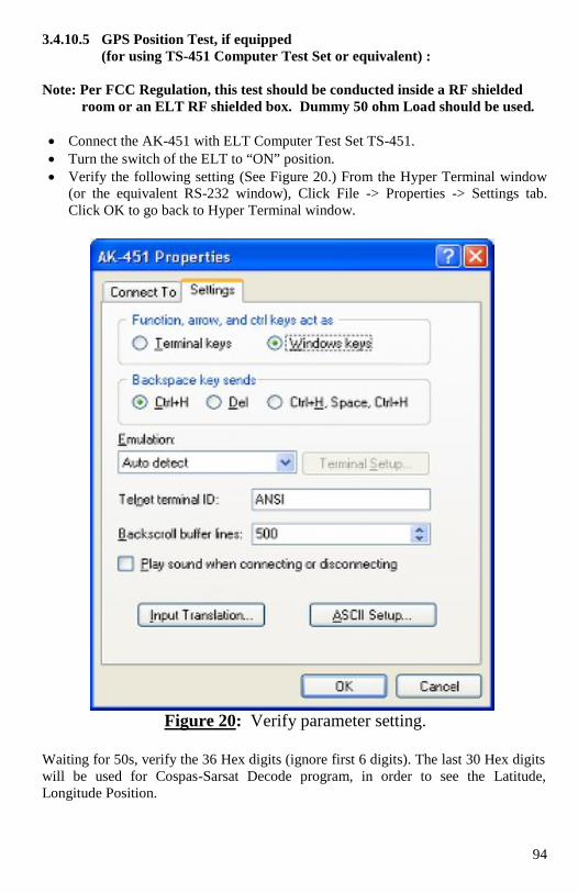
94
3.4.10.5 GPS Position Test, if equipped
(for using TS-451 Computer Test Set or equivalent) :
Note: Per FCC Regulation, this test should be conducted inside a RF shielded
room or an ELT RF shielded box. Dummy 50 ohm Load should be used.
Connect the AK-451 with ELT Computer Test Set TS-451.
Turn the switch of the ELT to “ON” position.
Verify the following setting (See Figure 20.) From the Hyper Terminal window
(or the equivalent RS-232 window), Click File -> Properties -> Settings tab.
Click OK to go back to Hyper Terminal window.
Figure 20: Verify parameter setting.
Waiting for 50s, verify the 36 Hex digits (ignore first 6 digits). The last 30 Hex digits
will be used for Cospas-Sarsat Decode program, in order to see the Latitude,
Longitude Position.
95
Note: When used with ELT's that are programmed for Standard Location 24 bit
protocol, the ELT to be program itself to the aircraft's 24 bit address. This
feature will allow the ELT to be transferred between aircraft. Re-register the
ELT with the Search and Rescue authority is required. This makes
maintenance of the ELT a simple matter of replacing the ELT. Note: There is
no electronic connection between TCAS or Mode S systems and the ELT, only
the ID number is common.
3.5 PERIODIC MAINTENANCE (INSTRUCTION FOR CONTINUED
AIRWORTHINESS FOR CANADIAN INSTALLATION:
REFERENCES:
Canadian Aviation Regulations CAR Standards: Part V – Airworthiness
Manual AWM 571: Appendix B.
Refer to Appendix B for Maintenance Check List with Compliance Cross References.
PURPOSE: Instructions for continued airworthiness, which shall include as a minimum, details of
approved batteries and sources of supply; battery replacement or recharge
instructions; battery capacity test procedures, if applicable; transmission or functional
test procedures; procedures necessary to accomplish the performance tests specified
in Chapter 571 Appendix B ; and for 406 MHz ELTs, instructions to verify the
aircraft 24 bit address protocol as applicable;
Appendix B
(a) Corrosion Inspection
(b) Operational Testing
(c) Performance Testing
(d) Battery Replacement and Recharging
(e) Shipping
IMPORTANT NOTES: The ELT must be “performance tested within the 12 month period preceding
installation in an Aircraft and within 12 months intervals thereafter…”
The following Supplemental Installation and Periodic Maintenance
requirements must be complied with, when installing the Model AK-451 ELT in
Canadian Aircraft:
SUPPLEMENTAL INSTALLATION
Installation and maintenance of the ELT must comply with Transport Canada
Airworthiness Manual Chapter AWM 551.104 (f)(4) Transmitter Remote Control
A Placard shall be fabricated and installed near the Remote Unit which states:
FOR AVIATION EMERGENCY USE ONLY
UNAUTHORIZED OPERATION PROHIBITED
96
PERIODIC MAINTENANCE (at least every year)
Note:
* These tests should be performed only within an RF Screen Room or Facility
providing shielding of RF Emissions.
* Using of ELT Test set TS-451 or equivalent test equipment is acceptable
3.5.1 Regular Periodic Maintenance Test
Perform Periodic Maintenance Test per paragraph 3.4 above, including all Test
paragraphs 3.4.1 through 3.4.10.
In addition to the Periodic Maintenance requirements prescribed in Paragraph 3.4, the
following Performance Testing must be performed, at least every year, to comply
with Canadian Aviation Regulations CAR Standards: Part V – Airworthiness Manual
571: Appendix B.
3.5.2 Power Output Test, Performance Testing
NOTE: Using of ELT Test set TS-451 or equivalent test equipment is acceptable
3.5.2.1 121.5/243.0 MHz Power Output:
Connect the equipment as shown below:
Note:
Use as fresh battery pack (12.5 ± 0.5 VDC nominal) or a 2 amp, 12.5 VDC power
supply as power source.
The test equipment specified in the following steps is only a recommendation. The
use of other manufacturer's models of test equipment capable of providing equivalent
measurement results is acceptable.
Set the Spectrum Analyzer as follows:
Center freq: 121.5 MHz
Span: 1 MHz
Resolution bandwidth: 1 MHz
Vertical display: 10dB/Div
Sweep: Auto
Peak/Avg: Peak
Reference level: 30 dBm
Time/Div: 20ms
ELT BNC
(top)
Connector
Applicable
attenuator
Spectrum
Analyzer
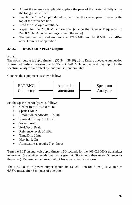
97
Adjust the reference amplitude to place the peak of the carrier slightly above
the top graticule fine.
Enable the "fine" amplitude adjustment. Set the carrier peak to exactly the
top of the reference line.
Read the displayed amplitude.
Repeat for the 243.0 MHz harmonic (change the "Center Frequency" to
243.0 MHz. All other settings remain the same).
The minimum allowed amplitude on 121.5 MHz and 243.0 MHz is 20 dBm,
after 3 minutes of operation.
3.5.2.2 406.028 MHz Power Output:
Note:
The power output is approximately (35.34 – 38.18) dBm. Ensure adequate attenuation
is inserted in-line between the ELT's 406.028 MHz output and the input to the
spectrum analyzer to protect the analyzer's input circuitry.
Connect the equipment as shown below:
Set the Spectrum Analyzer as follows:
Center freq: 406.028 MHz
Span: 1 MHz
Resolution bandwidth: 1 MHz
Vertical display: 10dB/Div
Sweep: Auto
Peak/Avg: Peak
Reference level: 30 dBm
Time/Div: 20ms
Max hold: On
Attenuator (as required) on Input
Turn the ELT on and wait approximately 50 seconds for the 406.028 MHz transmitter
to turn on (transmitter sends out first signal at 50 seconds then every 50 seconds
thereafter). Determine the power output from the stored waveform.
The 406.028 MHz power output should be (35.34 – 38.18) dBm (3.42W min to
6.58W max), after 3 minutes of operation.
ELT BNC
Connector
Applicable
attenuator
Spectrum
Analyzer
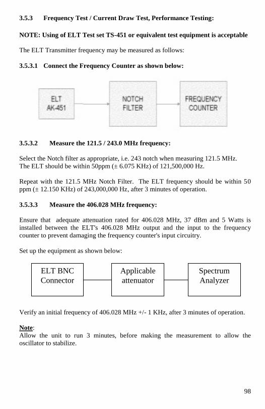
98
3.5.3 Frequency Test / Current Draw Test, Performance Testing:
NOTE: Using of ELT Test set TS-451 or equivalent test equipment is acceptable
The ELT Transmitter frequency may be measured as follows:
3.5.3.1 Connect the Frequency Counter as shown below:
3.5.3.2 Measure the 121.5 / 243.0 MHz frequency:
Select the Notch filter as appropriate, i.e. 243 notch when measuring 121.5 MHz.
The ELT should be within 50ppm (± 6.075 KHz) of 121,500,000 Hz.
Repeat with the 121.5 MHz Notch Filter. The ELT frequency should be within 50
ppm (± 12.150 KHz) of 243,000,000 Hz, after 3 minutes of operation.
3.5.3.3 Measure the 406.028 MHz frequency:
Ensure that adequate attenuation rated for 406.028 MHz, 37 dBm and 5 Watts is
installed between the ELT's 406.028 MHz output and the input to the frequency
counter to prevent damaging the frequency counter's input circuitry.
Set up the equipment as shown below:
Verify an initial frequency of 406.028 MHz +/- 1 KHz, after 3 minutes of operation.
Note:
Allow the unit to run 3 minutes, before making the measurement to allow the
oscillator to stabilize.
ELT BNC
Connector
Applicable
attenuator
Spectrum
Analyzer
99
3.5.3.4 Current draw tests:
CAUTION: The following tests involve measurement of the lithium battery pack.
Exercise extreme caution to avoid causing a short circuit condition
which will blow the fuse in the battery cell. It is recommended that only
an experience technician perform these tests.
A test harness (P/N TS-451-HN-1) may be ordered from Ameri-King Corp. at 714-
842-8555
All tests must be performed in an RF screen room or with the ELT in a shielded
container that will substantially attenuate the RF signal.
All "ON" state current measurements must be made with the RF outputs loaded with
50 ohms rated for 5 watts (either a resistive load or equipment with 50 ohm
impedance padded with 10 dB / 5 Watt attenuator, i.e. a spectrum analyzer).
NOTE: the ELT may activate (turn "ON") when the various connections are initially
made during the following current tests. This is normal. Press the RESET
Switch, to Reset the unit.
"OFF" Mode Current Measurement:
Remove the battery pack as described in Section 2.5.1
Disconnect the 2-pin harness
Install the test harness P/N TS-451-HN-1 and inline ammeter as shown in Fig. 4-2
Ensure the ELT is "OFF"
Measure the current with the ammeter. The measured current should be 0
microamps (uA).
"ARM" Mode Current Measurement:
Measure the current with the ammeter. The measured current should be not
more than 20 uA.
"ON" Mode Current Measurement:
Note: Current draw during this test may exceed 2.0 Amps during the 406.028 MHz
burst. Ensure the ammeter is set on the appropriate range to accommodate this
level of current.
Activate the ELT by select ON, allow it to stabilize.
The measured steady state current should not exceed 150 milliamps (mA).
When the 406.028 MHz module is on (generating the 406.028 MHz burst) the
current may exceed 2.0 amps.
Turn the ELT OFF
Disconnect the test harness P/N TS-451-HN1
Reconnect the 2-pin module power harness
Reinstall the battery pack as described in Section 4.3.4
100
3.5.4 AUDIO MODULATION, PERFORMANCE TESTING:
Perform the transmitter tests by activating the ELT and listening on 121.5 MHz.
The audio swept tone should “sound” like an ELT.
3.5.5 TRANSMITTER FUNCTIONAL TEST:
Perform Transmitter Functional Test per paragraph 3.3 above, including all Test
paragraphs 3.3.1 through 3.3.5.
Note: All ELT “ON” tests should be performed within the first five minutes of the
hour.
3.5.6 PERFORMANCE TEST MARKING AND LOG BOOK ENTRY:
Following satisfactory completion of all of the above Performance Testing, the date
on which the test was performed shall be marked on the external casing in a legible
and permanent manner.
Enter the test date and Technician Initials, as ELT Pass or Fail, into the aircraft Log
Book.
3.5.7 SHIPPING:
In order to prevent accidental activation of the ELT during transit, the ELT
ON/OFF/ARM Main Switch must be set in the “OFF” position.
Note: The ON/OFF/ARM Switch is lever locked type.
101
SECTION IV
REGISTRATION AND RESPONSBLE USE
4.1 REGISTRATION
4.1.1 Registration Importance
It is mandatory that the owner of this 406 MHz ELT registers it with the National
Authorities. All 406 MHz ELTs transmit a Unique Identifier Number (UIN) when
activated. This UIN is programmed in the ELT based on the country in which the
Aircraft operates. ELT Registration provides the Search and Rescue (SAR) forces
with emergency contact information, and will speed the launch of a rescue operation.
The National Authorities use the information to verify if an actual emergency exists.
Valuable Search and Rescue resources are wasted every year responding to false
alarms. For ELTs that are not registered, SAR authorities will not know who you are,
or who to contact regarding additional information of your current situation. This
could delay the launch of a rescue operation. A National Authority is the
governmental body that is responsible for ELT Registration Database administration
for the country for which the ELT is programmed.
Supplied with the ELT are pre-stamped envelope and ELT registration form with 15-
digit hex ID ELT programmed code and Country 3-digit code. This hex ID must be
the same as the 15-digit hex ID shown on the ELT name plate.
It is important to fill in the sticker “This ELT belongs to A/C Tail # _________.”
4.1.2 Where to register
The owner of a 406 MHz ELT should register it with the National Authority of which
the ELT was programmed, (typically the country where purchased), regardless of
where you use your ELT. Each ELT is programmed with a UIN for the country where
the unit is shipped, and will only be accepted for registration in that country. To
verify the country, for which an ELT is programmed, see the label with the UIN on
the back of the unit. Units that do not have a country specified on the UIN label are
programmed for the United States.
For a list of the national authorities in your area please go to:
http://www.cospassarsat.com/Management/listOfParticipants.htm
4.1.3 Registration in the United States
It is the Owner’s responsibility and required by law to Register 406 MHz ELTs that
are programmed for and purchased in the United States. The National Authority that
accepts registrations in the United States is the National Oceanic and Atmospheric
Administration (NOAA). The owner should complete the enclosed registration form
(Do not confuse this with the Ameri-King Corp. Warranty Card) and mail it with the
pre-addressed; postage paid envelope to (see Appendix F):
SARSAT BEACON REGISTRATION
E/SP3, RM 3320, FB-4
NOAA/NESDIS
5200 Auth Rd., Suitland, MD 20746-4304

102
ELT registration is also available online at: www.beaconregistration.noaa.gov
The information provided on the Registration Form is used only for rescue purposes.
The Registration Form should be filled out and mailed immediately. Registration can
be expedited by faxing the registration form or by completing the form online in the
event the ELT is to be placed in immediate use.
Typically, registration forms will be entered in the 406 MHz ELT Registration
Database within 48 hours of receipt. A confirmation letter, a copy of the actual
registration and a proof-of-registration decal will be mailed to you within two weeks.
When you receive these documents, please check the information carefully and affix
the decal to your ELT in the area marked “Beacon Decal here”, on the Bottom or Left
Side of ELT. If you do not receive confirmation, contact NOAA for additional
information at: +1-888-212-7283.
4.1.4 Registration in Canada
The National Authority in Canada is the NSS (National Search & Rescue Secretariat).
Canadian residents can register online at http://beacons.nss.gc.ca
For more information please contact the NSS at
Canadian Beacon Registry
CFB Trenton, PO Box 1000 Stn Forces
Astra, ON K0K 3W0
Phone 1-877-406-SOS1 (7671)
Fax 1-877-406-FAX8 (3298)
Email: [email protected]
Online: www.canadianbeaconregistry.forces.gc.ca
4.1.5 Registration Outside of the United States and Canada
In countries other than the United States, 406 MHz ELTs are registered with that
country’s National Authority at the time of Purchase. The Sales agent should assist in
filling out the forms and sending to that country’s National Authority. To verify that
the unit is properly programmed for that country, view the UIN label on the side of
the unit. In the event that the ELT is not programmed for the country in which it has
been purchased, the sales agent, (if properly equipped) can reprogram the unit for that
country. Go to https://www.406registration.com/ to register online (see Appendix G)
4.1.6 Change of ownership or contact information
It is the owner’s responsibility to advise the National Authority of any change in the
information on the registration form. If the current owner of the ELT is transferring
the to a new owner, the current owner is required to inform the National Authority by
Letter, Fax or telephone, of the name and address of the new owner. The new owner
of the ELT is required to provide the National Authority with all of the information
requested on the Registration form. This obligation transfers to all subsequent owners.
Registration forms are available from NOAA, call +1(888) 212-7283
103
4.1.7 Lost ELT’s
Inform NOAA immediately at 1-888-212-SAVE (7283), or your national authority,
that your ELT has been lost. They will update your ELT registration information
with the appropriate information.
4.1.8 Stolen ELT’s
Things That You Need To Do:
• Report to your local police department that the ELT has been stolen.
• Contact NOAA at 1-888-212-SAVE (7283), or your national authority, with the
following information so your registration information can be updated with the
appropriate remarks:
- Police Department Name
- Police Phone Number
- Police Case Number
If your ELT was to activate, the information you provide will be forwarded to the
appropriate Search and Rescue Authorities who will ensure that your ELT gets back
to you. And, if someone attempts to register a ELT reported as stolen, NOAA or your
national authority will notify the appropriate Police Department.
Visit the COSPAS-SARSAT website for more detailed information: www.cospas-
sarsat.org
4.2 RESPONSIBILITY
4.2.1 Responsible Use:
The Ameri-King AK-451 should only be used in situations of grave and imminent
danger! What exactly does this mean? Technically speaking you should only activate
your ELT when all other means of self rescue have been exhausted. This means you
have tried to use your cellular/satellite phone, signaling mirrors, strobe lights, or any
other safety device you may have. When all else fails and you feel your situation has
truly become extreme, ask yourself the following questions:
Am I in danger of losing life, limb, eye sight, or valuable property if I am not
rescued soon?
Am I in danger of not surviving the night or upcoming hours if not rescued soon?
If you answer yes with confidence to these questions, it is time to activate your ELT.
104
4.2.2 Preventing False Alarms
Ensure that your ELT is registered with NOAA or your national authority. This
does nothing to reduce false alarm rates, but does have a dramatic effect on the
impact of a false alarm. If the ELT is properly registered, the situation will be
resolved with a phone call most of the time. It will also help speed rescue in an
actual distress. Test your ELT in accordance with the recommendations enclosed
in this manual.
Use care when leaving your ELT and with whom you leave it with. Ensure that
they are aware of the device and know the ramifications of causing a false alarm.
A lot of false alarms are generated by curious individuals.
Maintain your ELT. Ensure that the batteries are within their expiration date and
that all manufacturer recommendations are followed.
Disposal of ELT: You should ensure that when you dispose of your ELT (for example when it is
damaged) it should be made inoperable, either by removing its batteries and, if
possible, returning it to Ameri-King Corp., or by demolishing it. Please update
your ELT Registration if you sell or dispose of your registered 406 MHz ELT.
Finally, realize that the COSPAS-SARSAT satellites are very good at what they
do, detecting emergency ELTs. An activation of a 406 MHz for just a few
seconds will usually be detected. After a few minutes, it will usually be detected
and located. This is good if you're in distress, but if you're not, you just generated
a false alarm.
4.2.3 Report false alarms
Should there be an inadvertent activation or false alarm, it must be reported to the
nearest search and rescue authorities. The information that should be reported
includes the ELT Unique Identifier Number (UIN), Date, Time, duration and cause of
activation, as well as location of ELT at the time of activation. Outside the United
States contact your National Authority.
4.2.4 To report false alarms in the United States contact any of the following:
Atlantic Ocean / Gulf of Mexico
USCG Atlantic Area Command Center ................... Tel: (757) 398-6390
Pacific Ocean Area
USCG Atlantic Area Command Center ................... Tel: (510) 437-3700
USCG HQ Command Center (From any location) .. Tel: (800) 323-7233
NOAA ...................................................................... Tel: 1-888-212-SAVE (7283)
AFRCC Console
(For official mission correspondence only) ............. Tel: 800-851-3051

105
SECTION V
WARRANTY
5.1 LIMITED WARRANTY
All equipments manufactured by Ameri-King Corp. are guaranteed against defective
materials and workmanship for a period of two years.
Any equipment found to be defective due to material and workmanship during this
limited warranty will be repaired and put in original manufactured operating
condition.
An option of extended third and fourth year limited warranty becomes valid at the end
of this second year, which will warrant to the original owner.
This Ameri-King Corp. warranty is void unless the Warranty Registration Card is
filled out and returned to Ameri-King Corp. within 15 days after original installation.
Ameri-King Corp.’s liability under this warranty is limited to servicing, repairing,
replacing or adjusting any equipment returned prepaid to the factory by express
written or oral authorization for that purpose and to repair or replace defective parts
thereof. This limited warranty does not include any damage caused by the leakage of
batteries. Repaired equipment will be returned to the equipment user freight pre-paid.
Shipping charge shall be paid both ways by the Customers.
Upon discovery of a condition believed to be caused by a defect in manufacturing,
Ameri-King Corp. without prior authorization. Any equipment returned to Ameri-
King Corp. without prior authorization. Any equipment returned to Ameri-King
Corp. should be accompanied by a failure report, in writing, giving full particulars in
support of the claim.
This limited warranty does not cover or apply to any of the followings, including:
misuses of the equipment; installation or operation not in accordance with factory
instructions; accidences or negligent damage; alterations of any manner; repair by
other factory; changes in calibration occurring as a result of normal use of equipment;
the cost of labor, material, or other expense incidental to the repair, installation,
removal from the aircraft or replacement of the equipment; damaged during shipment
or installation; any personal injuries or damage to property resulting from the
installation or the operation of the equipment user assumes the risks of all such
injuries or damage. In such cases, the repair will be billed at cost. An estimate will
be submitted for approval before repair is initiated.
Any equipment that is returned for warranty and found not to be defective shall be
charged a minimum handling and service charge and returned prepaid or C.O.D.
Shipping charge shall be paid both ways by the Customers.
106
No warranty will be activated for Ameri-King Corp. products unless the installation is
approved by an FAA Certified Installer and the warranty card is completed by the
supplying dealer or upon receipt by Ameri-King Corp. of form(s) 337 or 8130-().
THE IMPLIED WARRANTY AND ALL OTHER IMPLIED WARRANTIES
ARE HEREBY EXCULED. AMERI-KING CORP. MAKES NO OTHER
WARRANTY OR REPRESENTATION OF ANY KIND WHATSOEVER
EXPRESSED OR IMPLIED, AND ALL IMPLIED WARRANTIES
INCLUDING ANY WARRANTY OF MERCHANTABILITY OR FITNESS
FOR A PARTICULAR PURPOSE ARE HEREBY DISCLAIMED.
AMERI-KING CORP.’S MAXIMUM LIABILITY HEREUNDER IS LIMITED
TO THE PURCHASED PRICE OF THE PRODUCT. IN NO EVEN SHALL
AMERI-KING CORP. BE LIABLE FOR ANY DAMAGES OF ANY NATURE
ARISING FROM THE SALE OR USE OF THE PRODUCT, WHETHER
BASED IN CONTRACT, TORT, STRICT LIABILITY OR OTHERWISE.
5.2 REPAIR SERVICE/BATTERY REPLACEMENT SERVICE
All equipments manufactured by Ameri-King Corp. must be repaired at the facility of
Ameri-King Corp.
The entire repair service shall be performed and completed within 3 days upon
repairing estimate is approved by equipment user or installation dealer.
Shipping charge shall be paid both ways by the Customers.
IMPORTANT NOTE:
In order to prevent accidental activation of the ELT during transit, the ELT
ON/OFF/ARM Main Switch must be set in the “OFF” position.
Note: The ON/OFF/ARM Switch is lever locked type.
If your ELT is to be returned to Ameri-King Corp. it should be made inoperable, by
removing its batteries.
If your ELT is to be returned to Ameri-King Corp. with the batteries still installed, it
should be wrapped in tin foil to prevent transmission of signals during shipment.
5.3 FACTORY COMPREHENSIVE TEST SERVICE
Factory Comprehensive Test Service including Digital Message, GPS Position, G-
Switch activation levels testing, RF Peak Effective Radiated Power, Operating Carrier
Frequency, Modulation Characteristics, Duty Cycles and Activation Monitor are
available. There is a service charge for this service. All equipments returned for
Factory Comprehensive Test Service must be sent freight prepaid.
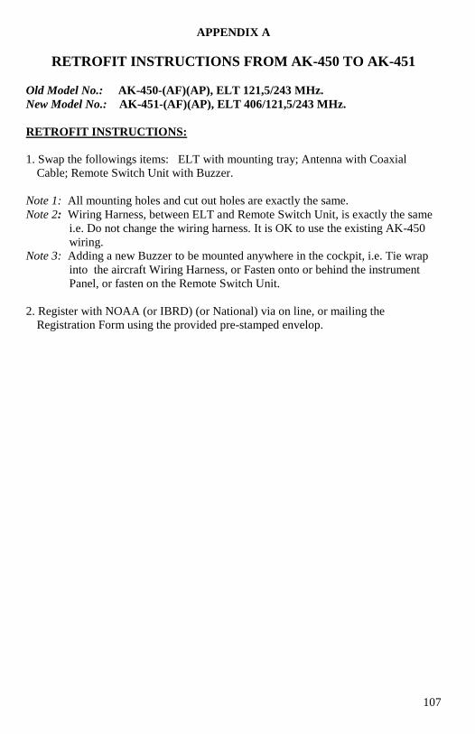
107
APPENDIX A
RETROFIT INSTRUCTIONS FROM AK-450 TO AK-451
Old Model No.: AK-450-(AF)(AP), ELT 121,5/243 MHz.
New Model No.: AK-451-(AF)(AP), ELT 406/121,5/243 MHz.
RETROFIT INSTRUCTIONS:
1. Swap the followings items: ELT with mounting tray; Antenna with Coaxial
Cable; Remote Switch Unit with Buzzer.
Note 1: All mounting holes and cut out holes are exactly the same.
Note 2: Wiring Harness, between ELT and Remote Switch Unit, is exactly the same
i.e. Do not change the wiring harness. It is OK to use the existing AK-450
wiring.
Note 3: Adding a new Buzzer to be mounted anywhere in the cockpit, i.e. Tie wrap
into the aircraft Wiring Harness, or Fasten onto or behind the instrument
Panel, or fasten on the Remote Switch Unit.
2. Register with NOAA (or IBRD) (or National) via on line, or mailing the
Registration Form using the provided pre-stamped envelop.

108

109

110

111

112

113

114
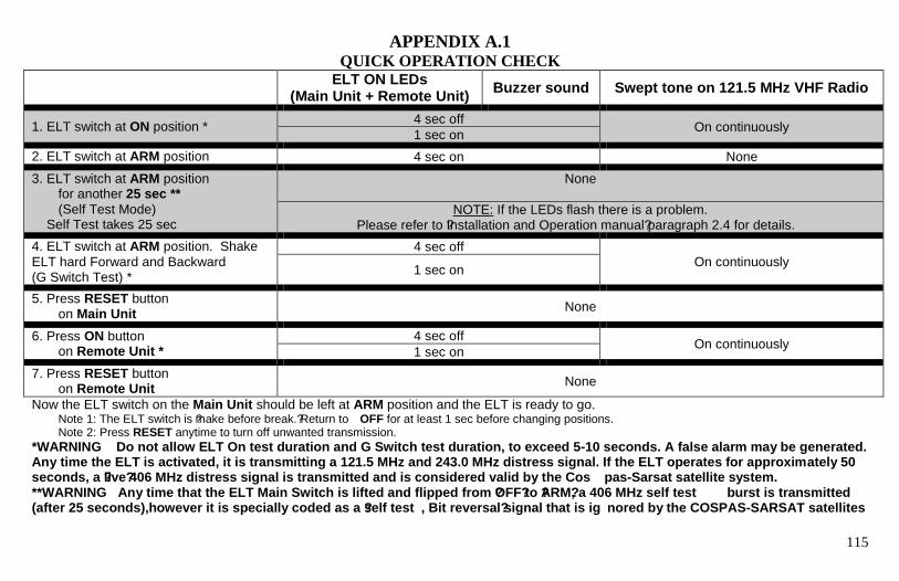
115
APPENDIX A.1 QUICK OPERATION CHECK
ELT ON LEDs (Main Unit + Remote Unit)
Buzzer sound Swept tone on 121.5 MHz VHF Radio
1. ELT switch at ON position * 4 sec off
On continuously 1 sec on
2. ELT switch at ARM position 4 sec on None
3. ELT switch at ARM position for another 25 sec **
(Self Test Mode) Self Test takes 25 sec
None
NOTE: If the LEDs flash there is a problem. Please refer to ?Installation and Operation manual? paragraph 2.4 for details.
4. ELT switch at ARM position. Shake
ELT hard Forward and Backward (G Switch Test) *
4 sec off On continuously
1 sec on
5. Press RESET button on Main Unit
None
6. Press ON button on Remote Unit *
4 sec off On continuously
1 sec on
7. Press RESET button on Remote Unit
None
Now the ELT switch on the Main Unit should be left at ARM position and the ELT is ready to go. Note 1: The ELT switch is ?make before break.? Return to OFF for at least 1 sec before changing positions. Note 2: Press RESET anytime to turn off unwanted transmission.
*WARNING Do not allow ELT On test duration and G Switch test duration, to exceed 5-10 seconds. A false alarm may be generated. Any time the ELT is activated, it is transmitting a 121.5 MHz and 243.0 MHz distress signal. If the ELT operates for approximately 50 seconds, a ?live? 406 MHz distress signal is transmitted and is considered valid by the Cos pas-Sarsat satellite system. **WARNING Any time that the ELT Main Switch is lifted and flipped from ?OFF? to ?ARM?, a 406 MHz self test burst is transmitted (after 25 seconds),however it is specially coded as a ?self test , Bit reversal ? signal that is ig nored by the COSPAS-SARSAT satellites
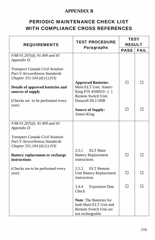
116
APPENDIX B
PERIODIC MAINTENANCE CHECK LIST
WITH COMPLIANCE CROSS REFERENCES
REQUIREMENTS
TEST PROCEDURE
Paragraphs
TEST
RESULT
PASS FAIL
FAR 91.207(d); 91.409 and 43
Appendix D.
Transport Canada Civil Aviation
Part V Airworthiness Standards
Chapter 551.104 (d) (1) (VI)
Details of approved batteries and
sources of supply
(Checks are to be performed every
year)
Approved Batteries:
Main ELT Unit: Ameri-
King P/N 4500010 –( )
Remote Switch Unit:
Duracell DL1/3NB
Source of Supply: Ameri-King
FAR 91.207(d); 91.409 and 43
Appendix D.
Transport Canada Civil Aviation
Part V Airworthiness Standards
Chapter 551.104 (d) (1) (VI)
Battery replacement or recharge
instructions
(Checks are to be performed every
year)
2.5.1 ELT Main
Battery Replacement
instructions
2.5.2 ELT Remote
Unit Battery Replacement
instructions
3.4.4 Expiration Date
Check
Note: The Batteries for
both Main ELT Unit and
Remote Switch Unit are
not rechargeable
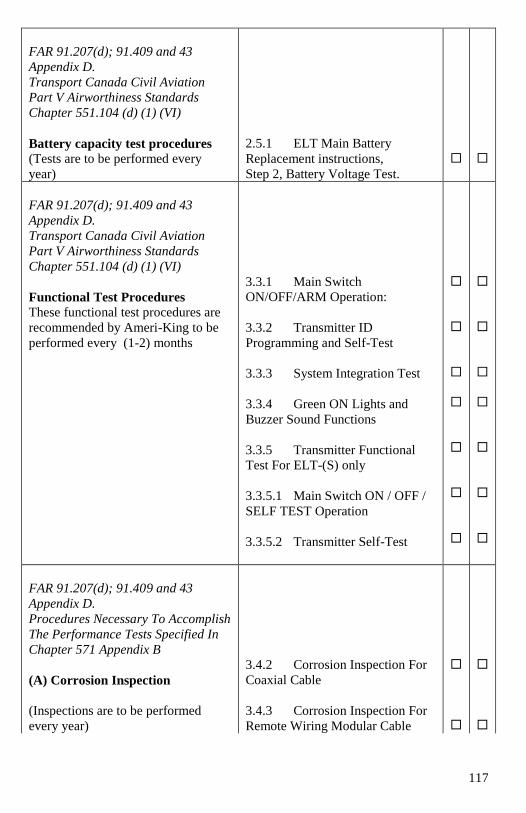
117
FAR 91.207(d); 91.409 and 43
Appendix D.
Transport Canada Civil Aviation
Part V Airworthiness Standards
Chapter 551.104 (d) (1) (VI)
Battery capacity test procedures
(Tests are to be performed every
year)
2.5.1 ELT Main Battery
Replacement instructions,
Step 2, Battery Voltage Test.
FAR 91.207(d); 91.409 and 43
Appendix D.
Transport Canada Civil Aviation
Part V Airworthiness Standards
Chapter 551.104 (d) (1) (VI)
Functional Test Procedures These functional test procedures are
recommended by Ameri-King to be
performed every (1-2) months
3.3.1 Main Switch
ON/OFF/ARM Operation:
3.3.2 Transmitter ID
Programming and Self-Test
3.3.3 System Integration Test
3.3.4 Green ON Lights and
Buzzer Sound Functions
3.3.5 Transmitter Functional
Test For ELT-(S) only
3.3.5.1 Main Switch ON / OFF /
SELF TEST Operation
3.3.5.2 Transmitter Self-Test
FAR 91.207(d); 91.409 and 43
Appendix D.
Procedures Necessary To Accomplish
The Performance Tests Specified In
Chapter 571 Appendix B
(A) Corrosion Inspection
(Inspections are to be performed
every year)
3.4.2 Corrosion Inspection For
Coaxial Cable
3.4.3 Corrosion Inspection For
Remote Wiring Modular Cable
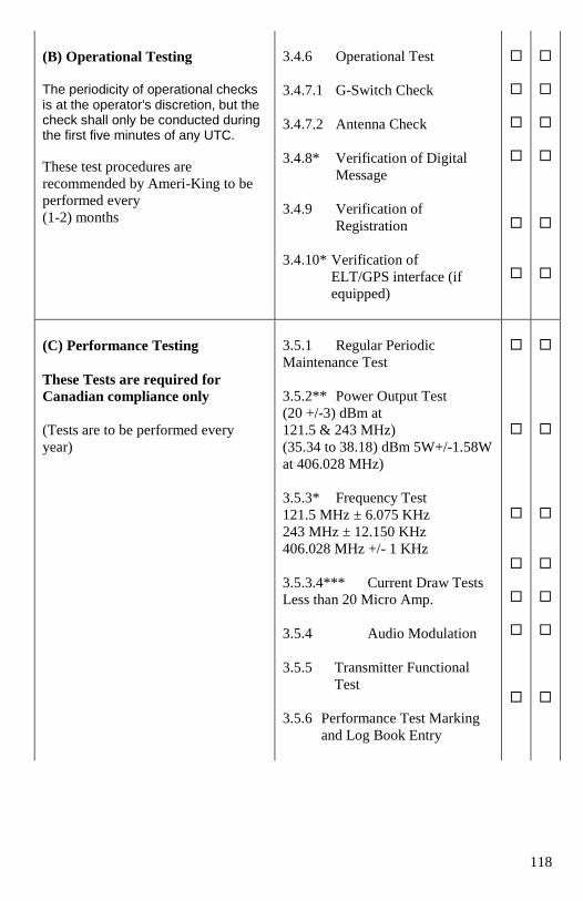
118
(B) Operational Testing
The periodicity of operational checks is at the operator's discretion, but the check shall only be conducted during the first five minutes of any UTC.
These test procedures are
recommended by Ameri-King to be
performed every
(1-2) months
3.4.6 Operational Test
3.4.7.1 G-Switch Check
3.4.7.2 Antenna Check
3.4.8* Verification of Digital
Message
3.4.9 Verification of
Registration
3.4.10* Verification of
ELT/GPS interface (if
equipped)
(C) Performance Testing
These Tests are required for
Canadian compliance only
(Tests are to be performed every
year)
3.5.1 Regular Periodic
Maintenance Test
3.5.2** Power Output Test
(20 +/-3) dBm at
121.5 & 243 MHz)
(35.34 to 38.18) dBm 5W+/-1.58W
at 406.028 MHz)
3.5.3* Frequency Test
121.5 MHz ± 6.075 KHz
243 MHz ± 12.150 KHz
406.028 MHz +/- 1 KHz
3.5.3.4*** Current Draw Tests
Less than 20 Micro Amp.
3.5.4 Audio Modulation
3.5.5 Transmitter Functional
Test
3.5.6 Performance Test Marking
and Log Book Entry
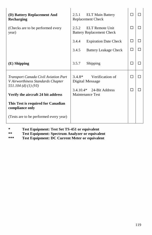
119
(D) Battery Replacement And
Recharging
(Checks are to be performed every
year)
2.5.1 ELT Main Battery
Replacement Check
2.5.2 ELT Remote Unit
Battery Replacement Check
3.4.4 Expiration Date Check
3.4.5 Battery Leakage Check
(E) Shipping
3.5.7 Shipping
Transport Canada Civil Aviation Part
V Airworthiness Standards Chapter
551.104 (d) (1) (VI)
Verify the aircraft 24 bit address
This Test is required for Canadian
compliance only
(Tests are to be performed every year)
3.4.8* Verification of
Digital Message
3.4.10.4* 24-Bit Address
Maintenance Test
* Test Equipment: Test Set TS-451 or equivalent
** Test Equipment: Spectrum Analyzer or equivalent
*** Test Equipment: DC Current Meter or equivalent
120
APPENDIX C
EMERGENCY LOCATOR TRANSMITTER RECOMMENDED
SUPPLEMENTAL INSPECTION PROCEDURE
(FAR PART 91 OPERATIONS)
FAR Part 91.207 Paragraph (d); Part 43 Appendix D (i); FAR Part 91.407
14 CFR Parts 25, and 29 [Docket No. 26180; Amendment Nos. 25-82, 29-33]
FAA ACTION NOTICE A 8150.3
FAA Part 91.207
(d) Each emergency locator transmitter required by paragraph (a) of this section must
be inspected within 12 calendar months after the last inspection for—
(1) Proper installation;
(2) Battery corrosion;
(3) Operation of the controls and crash sensor; and
(4) The presence of a sufficient signal radiated from its antenna.
INSPECTION
(d) Each emergency locator transmitter must be inspected within 12 calendar months
after the last inspection for -
INSPECTION
(1) Proper installation;
According to the ELT mfg instructions and
According to FAA supplemental inspection procedures in Notice A8310.1
According to AC91-44A
INSPECTION
Remove all interconnections to the ELT unit and ELT antenna. Visually inspect
and confirm proper seating of all connector pins. Special attention should be
given to coaxial center conductor pins which are prone to retracting into the
connector housing.
Remove the ELT from the mount and inspect the mounting hardware. All
required mounting hardware should be installed and secured.
INSPECTION
(2) Battery corrosion;
Gain access to the ELT battery and inspect. No corrosion should be detectable.
Verify the ELT battery is approved and check its expiration date.
INSPECTION
(3) Operation of the controls and crash sensor; and Activate the ELT using an applied
force. Consult the ELT manufacturer's instructions before activation. The
direction for mounting and force activation is indicated on the ELT.
121
INSPECTION
A TSO-C91 ELT can be activated by using a quick rap with the palm. A TSO-C91a
ELT can be activated by using a rapid forward (throwing) motion coupled by a rapid
reversing action.
INSPECTION
Verify that the ELT is activated using a wattmeter, the airplane's VHF radio
communications receiver tuned to 121.5 MHz, or other means.
INSPECTION
Reinstall the ELT into its mount and verify the proper direction for crash activation.
Reconnect all cables. They should have some slack at each end and should be
properly secured to the airplane structure for support and protection.
INSPECTION
(4) The presence of a sufficient signal radiated from its antenna Activate the ELT
using the "on" or ELT "test" switch. A low-quality amplitude modulation (AM)
broadcast radio receiver should be used to determine if energy is being transmitted
from the antenna. (continue)
INSPECTION
When the antenna of the AM broadcast radio receiver (tuning dial on any setting) is
held about 6 inches from the activated ELT antenna, the ELT aural tone will be heard.
INSPECTION
Verify that all switches are properly labeled and positioned.
TEMPORARY REMOVAL
An aircraft [may be operated] during any period for which the transmitter has been
temporarily removed for inspection, repair, modification, or replacement, subject to
the following:
TEMPORARY REMOVAL
No person may operate the aircraft unless the aircraft records contain an entry which
includes the date of initial removal, the make, model, serial number, and reason for
removing the transmitter, and a placard located in view of the pilot to show "ELT not
installed."
TEMPORARY REMOVAL
No person may operate the aircraft more than 90 days after the ELT is initially
removed from the aircraft
FAA Part 43 Appendix D
(i) Each person performing an annual or 100-hour inspection shall inspect (where
applicable) the following components of the radio group:
(1) Radio and electronic equipment--for improper installation and insecure
mounting.
122
(2) Wiring and conduits--for improper routing, insecure mounting, and obvious
defects.
(3) Bonding and shielding--for improper installation and poor condition.
(4) Antenna including trailing antenna--for poor condition, insecure mounting, and
improper operation.
Sec. 91.407
Operation after maintenance, preventive maintenance, rebuilding, or alteration
(a) No person may operate any aircraft that has undergone maintenance, preventive
maintenance, rebuilding, or alteration unless--
(1) It has been approved for return to service by a person authorized under Sec.
43.7 of this chapter; and
(2) The maintenance record entry required by Sec. 43.9 or Sec. 43.11, as
applicable, of this chapter has been made.
(b) No person may carry any person (other than crewmembers) in an aircraft that has
been maintained, rebuilt, or altered in a manner that may have appreciably
changed its flight characteristics or substantially affected its operation in flight
until an appropriately rated pilot with at least a private pilot certificate flies the
aircraft, makes an operational check of the maintenance performed or alteration
made, and logs the flight in the aircraft records.
(c) The aircraft does not have to be flown as required by paragraph (b) of this section
if, prior to flight, ground tests, inspection, or both show conclusively that the
maintenance, preventive maintenance, rebuilding, or alteration has not appreciably
changed the flight characteristics or substantially affected the flight operation of
the aircraft.
FAA Action Notice A 8150.3
1. Remove all interconnections to the ELT Main Unit and ELT antenna. Visually
inspect and confirm proper seating of all connector pins. Special attention
should be given to coaxial center conductor pins, which are prone to retracting
into the connector housing.
2. Remove ELT from the mount and inspect the mounting hardware. All required
mounting hardware should be reinstalled and secured.
3. Gain access to the ELT battery and inspect. No corrosion should be detectable.
Verify that the ELT battery is approved and check its expiration date.
4. Activate the ELT using applied force. The direction for mounting and force
activation is indicated on the ELT. A TSO-C91a ELT can be activated by
using a quick rap with the palm. A TSO-C91a ELT can be activated by using a
rapid forward (throwing) motion coupled by a rapid reversing action.
Manufacturer’s instructions should be referred to prior to activation. Verify
that the ELT has been activated by use of a Wattmeter, the airplane’s VHFG
Radio Communications Receiver when tuned to 121.5 MHz, or other means.
(See Note 1).
5. Reinstall the ELT into its mount and verify the proper direction for crash
activation. Reconnect all cables. They should have some slack at each end be
properly secured to the Airplane structure for support and protection.
123
6. Activate the ELT using the “ON” of “Test” Switch. A low quality AM
Broadcast Radio Receiver should be sued to determine if energy is being
transmitted from the Antenna. When the Antenna of this Radio (tuning dial on
any setting) is held about 6 inches from the activated ELT Antenna, the ELT
Aural tone will be heard (see notes 2 and 3).
7. Verify that all switches are properly labeled and positioned.
Note 1:
This is not a measured check. It only indicates that the G-Switch is working.
Note 2: This is not a measured check, but it does provide confidence that the Antenna is
radiating with sufficient power to aid search and rescue. The Aircraft’s VHF
Receiver, tuned to 121.5 MHz, may also be sued. This Receiver, however, is
more sensitive and could pick up a weak signal even if the radiating ELT’s
Antenna is disconnected. Thus, it does not check the integrity of the ELT System
or provide the same level of confidence, as does an AM Radio.
Note 3: Because the ELT radiates on the emergency frequency, the Federal
Communications Commission allows these tests to be conducted only within the
first 5 minutes after any hour.
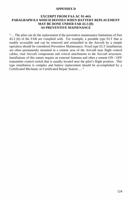
124
APPENDIX D
EXCERPT FROM FAA AC 91-44A
PARAGRAPH 8.A WHICH DEFINES WHEN BATTERY REPLACEMENT
MAY BE DONE UNDER FAR 43.3 (H)
AS PREVENTIVE MAINENANCE
“… The pilot can do the replacement if the preventive maintenance limitations of Part
43.3 (h) of the FAR are complied with. For example, a portable type ELT that is
readily accessible and can be removed and reinstalled in the Aircraft by a simple
operation should be considered Preventive Maintenance. Fixed type ELT installations
are often permanently mounted in a remote area of the Aircraft near flight control
cables, vital Aircraft components and critical attachments to the Aircraft structures.
Installations of this nature require an external Antenna and often a remote ON / OFF
transmitter control switch that is usually located near the pilot’s flight position. This
type installation is complex and battery replacement should be accomplished by a
Certificated Mechanic or Certificated Repair Station … “
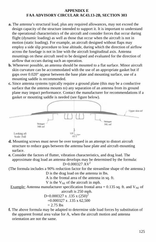
125
APPENDIX E
FAA ADVISORY CIRCULAR AC43.13-2B, SECTION 303
a. The antenna’s structural load, plus any required allowances, may not exceed the
design capacity of the structure intended to support it. It is important to understand
the operational characteristics of the aircraft and consider forces that occur during
flight (dynamic loading) as well as those that occur when the aircraft is not in
motion (static loading). For example, an aircraft designed without flaps may
employ a side slip procedure to lose altitude, during which the direction of airflow
across the fuselage is not in line with the aircraft longitudinal axis. Antenna
mountings on these aircraft need to be designed and evaluated for the direction of
airflow that occurs during such an operation.
b. Whenever possible, an antenna should be mounted to a flat surface. Minor aircraft
skin curvature can be accommodated with the use of an appropriate gasket but if
gaps over 0.020" appear between the base plate and mounting surface, use of a
mounting saddle is recommended.
c. Since antenna systems typically require a ground plane (this may be a conductive
surface that the antenna mounts to) any separation of an antenna from its ground
plane may impact performance. Contact the manufacturer for recommendations if a
gasket or mounting saddle is needed (see figure below).
d. Mounting screws must never be over torqued in an attempt to distort aircraft
structure to reduce gaps between the antenna base plate and aircraft-mounting
surface.
e. Consider the factors of flutter, vibration characteristics, and drag load. The
approximate drag load an antenna develops may be determined by the formula:
D=0.000327 AV2
(The formula includes a 90% reduction factor for the streamline shape of the antenna.)
D is the drag load on the antenna in lbs.
A is the frontal area of the antenna in sq. ft.
V is the VNE of the aircraft in mph.
Example: Antenna manufacturer specification frontal area = 0.135 sq. ft. and VNE of
aircraft is 250 mph.
D=0.000327 x .135 x (250)2
=0.000327 x .135 x 62,500
= 2.75 lbs
f. The above formula may be adapted to determine side load forces by substitution of
the apparent frontal area value for A, when the aircraft motion and antenna
orientation are not the same.

126
APPENDIX F
REGISTERING A 406 MHz BEACON IN THE U.S.A.
Important Notice - Please Read Before Completing Registration
Registration is an important facet for all Cospas-Sarsat 406 MHz emergency beacons. Not only is it
required by Federal Regulations but the information you furnish is used by Search And Rescue (SAR) agencies in the event of beacon activation. The registration information is an important tool to assist the
United States Coast Guard, United States Air Force, and other SAR agencies in locating and quickly
responding to you, your vessel, or your aircraft. Failure to register your beacon may delay a rescue response. Accurate, up-to-date registration information will also be used to conserve resources by helping
to eliminate false alert deployments, as an inadvertent activation can be resolved with a phone call.
There is no charge for beacon registration. This is a service provided by the U.S. National Oceanic and
Atmospheric Administration (NOAA).
All online registrations will be entered into the National 406 MHz Beacon Registration Database on the
same day of entry. Registration forms received via postal mail will be entered within 2 business days of
receipt. For online registrations, a confirmation letter with your completed registration information form
will be sent immediately via e-mail or fax (if provided). Confirmation letters sent via postal mail should
arrive within two weeks. Once your registration confirmation is received, please review all information.
Any changes or updates to your registration information can be done via the internet, fax, e-mail or postal mail. If you do not receive your registration confirmation from NOAA on the same day you submit it over
the internet or within two weeks if you submit it by postal mail, please call NOAA toll-free at: 1-888-212-
SAVE (7283) or 301-817-4515 for assistance.
After initial registration (or re-registration) you will receive a NOAA Proof of Registration Decal by postal
mail. This decal is to be affixed to the beacon and should be placed in such a way that it is clearly visible. If for some reason you do not receive the registration decal within two weeks, please-6 call NOAA toll-free
at: 1-888-212-SAVE (7283) or 301-817-4515.
Failure to register, re-register (as required every two years), or to notify NOAA of any changes to the status
of your 406 MHz beacon could result in penalties and/or fines being issued under Federal Law. The owner
or user of the beacon is required to notify NOAA of any changes to the registration information at any time.
By submitting this registration the owner, operator, or legally authorized agent declares under penalty of
law that all information in the registration information is true, accurate, and complete. Providing
information that is knowingly false or inaccurate may be punishable under Federal Statutes. Solicitation of this information is authorized by Title 47 - Parts 80, 87, and 95 of the U.S. Code of Federal Regulations
(CFR). Additional registration forms can be found on the NOAA-SARSAT website:
www.sarsat.noaa.gov or www.beaconregistration.noaa.gov.
Please note, NOAA will complement or update your registration information accordingly if your
registration has expired and credible information is provided from SAR sources. NOAA will also seek information from other databases to update and/or complement the existing information for an expired
beacon registration. Although the information provided will become a matter of public record, there is no
intent to circulate beyond its intended purpose, i.e., to assist SAR agencies in carrying out their mission. Public reporting burden for the collection of this information is estimated to average 15 minutes per
response, including the time for reviewing instructions, searching existing data sources, and completing and
reviewing the collection of information. Comments regarding this burden or any other aspect of this collection of information, including suggestions for reducing this burden should be sent to:
SARSAT Beacon Registration
NSOF, E/SPO53
1315 East West Hwy Silver Spring, MD 20910
Or call: 1-888-212-SAVE (7283) or 301-817-4515
Finally, false alerts remain a chief concern for SAR agencies. We ask that you carefully refer to the beacon’s user manual for instructions on properly operating, installing, testing, performing required
maintenance, and/or stowage of your beacon. We find that these are important factors in reducing the
number of false alerts. Please use the utmost care at all times!
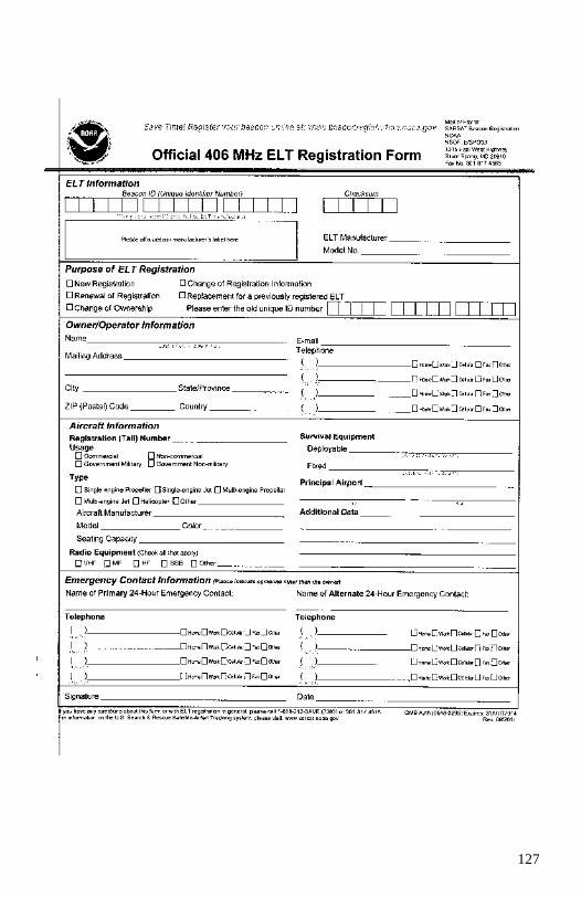
127
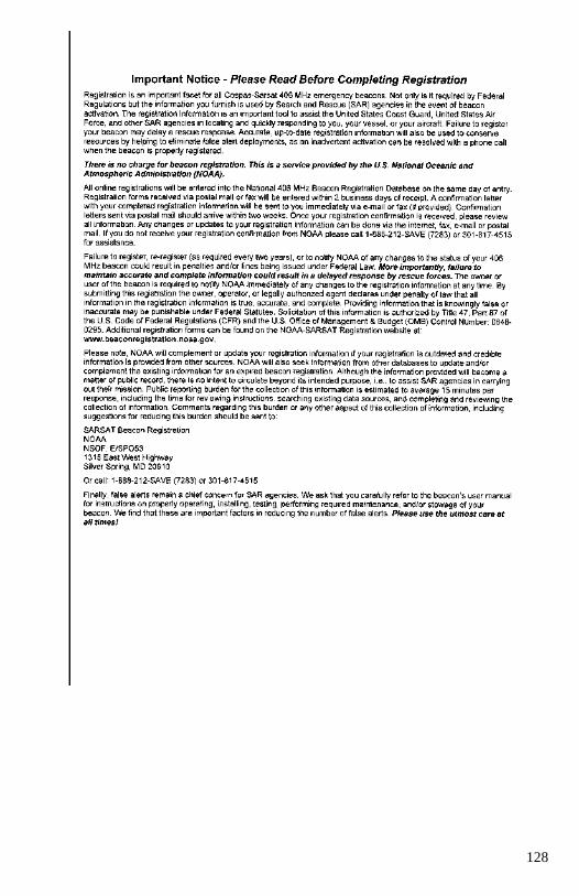
128
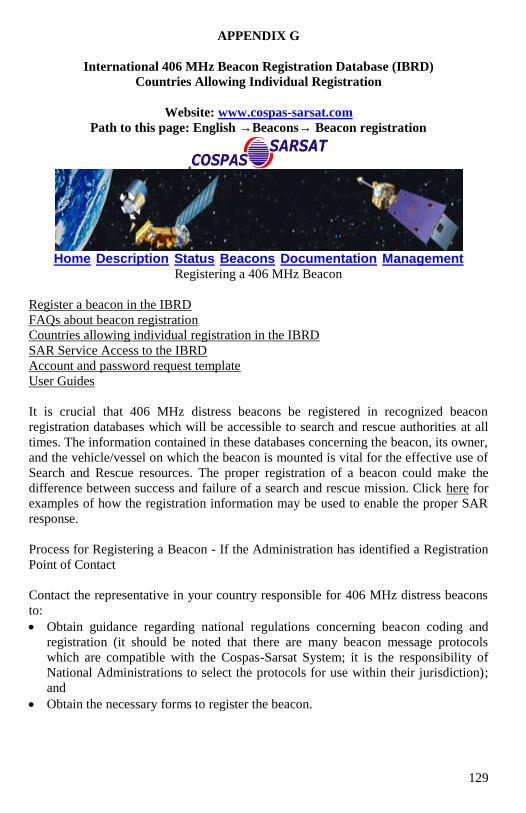
129
APPENDIX G
International 406 MHz Beacon Registration Database (IBRD)
Countries Allowing Individual Registration
Website: www.cospas-sarsat.com
Path to this page: English →Beacons→ Beacon registration
Home Description Status Beacons Documentation Management
Registering a 406 MHz Beacon
Register a beacon in the IBRD
FAQs about beacon registration
Countries allowing individual registration in the IBRD
SAR Service Access to the IBRD
Account and password request template
User Guides
It is crucial that 406 MHz distress beacons be registered in recognized beacon
registration databases which will be accessible to search and rescue authorities at all
times. The information contained in these databases concerning the beacon, its owner,
and the vehicle/vessel on which the beacon is mounted is vital for the effective use of
Search and Rescue resources. The proper registration of a beacon could make the
difference between success and failure of a search and rescue mission. Click here for
examples of how the registration information may be used to enable the proper SAR
response.
Process for Registering a Beacon - If the Administration has identified a Registration
Point of Contact
Contact the representative in your country responsible for 406 MHz distress beacons
to:
Obtain guidance regarding national regulations concerning beacon coding and
registration (it should be noted that there are many beacon message protocols
which are compatible with the Cospas-Sarsat System; it is the responsibility of
National Administrations to select the protocols for use within their jurisdiction);
and
Obtain the necessary forms to register the beacon.
130
Process for Registering a Beacon in the Cospas-Sarsat International 406 MHz Beacon
Registration Database (IBRD)
Your country may have elected to allow you to directly register your beacon in the
International 406 MHz Beacon Registration Database (IBRD), available online at
www.406registration.com. Click here for a list of these countries.
The IBRD became operational on the 16 January 2006. It provides capability to
register 406 MHz distress beacons and has extensive online help capabilities.
Individual beacon owners may register their beacons and select their own passwords
during the registration process if this use of the IBRD has been allowed by their
national Administration.
You will need the following information to register a beacon:
Beacon Hexadecimal Identification (15 Hexadecimal characters)
Owner name and phone number
Emergency contact name and phone number
Vehicle type (selectable from a menu)
Vehicle name, MMSI, call sign or identification number (except for PLBs).
Cospas-Sarsat will only accept beacon registrations submitted via the online facilities
of the IBRD. Beacon registrations submitted in paper format or via other
communication facilities will not be accepted. The Cospas-Sarsat Secretariat
([email protected]) is available to answer questions from National
Administrations concerning beacon coding and registration matters.
Administration User Accounts
The IBRD is freely available to users with no access to national registration facilities
and to Administrations who wish to avail themselves of the facility to make their
national beacon registration data more available to SAR services.
SAR Services and others wishing to query the IBRD will require passwords issued by
the Cospas-Sarsat Secretariat. In order to acquire appropriate passwords to access the
IBRD, National Administrations should:
Designate a National IBRD Point of Contact, and
Request that the Cospas-Sarsat Secretariat allocate user identifications and
passwords to their National IBRD Point of Contact.
The password and user identification request must be provided in writing to the
Database Administrator (i.e. the Cospas-Sarsat Secretariat) and must carry the
signature of the Cospas-Sarsat/IMO/ICAO Representative of the Administration. For
a letter template, please click here.
[Contact Us | Related Sites | Location]
700 de la Gauchetière West, Suite 2450, Montreal (Quebec) H3B 5M2 Canada
Email: [email protected] Tel: +1 514 954 6761

131
Sorted By Country Name Sorted By Country Code
Country Code Country Name Country Code Country Name
401 Afghanistan 201 Albania
201 Albania 202 Andorra
202 Andorra 204 Azores
301 Anguilla 206 Belarus
216 Armenia 208 Vatican
608 Ascension 214 Moldova
204 Azores 216 Armenia
408 Bahrain 243 Hungary
405 Bangladesh 255 Madeira
314 Barbados 262 Montenegro
206 Belarus 268 San Marino
312 Belize 270 Czech Republic
610 Benin 274 Macedonia
410 Bhutan 278 Slovenia
720 Bolivia 301 Anguilla
611 Botswana 312 Belize
508 Brunei 314 Barbados
633 Burkina Faso 319 Cayman Islands
506 Burma 323 Cuba
609 Burundi 325 Dominica
364 Turks And Caicos
Islands 327 Dominican Republic
514, 515 Cambodia 330 Grenada
617 Cape Verde 332 Guatemala
319 Cayman Islands 336 Haiti
612 Central African
Republic 339 Jamaica
670 Chad 341 St Kitts
616 Comoros 343 St Lucia
615 Congo 348 Montserrat
323 Cuba 350 Nicaragua
270 Czech Republic
351, 352, 353,
354, 355, 356,
357, 371, 372
Panama
621 Djibouti 359 El Salvador
325 Dominica 362 Trinidad
327 Dominican Republic 364 Turks And Caicos
Islands
359 El Salvador 378 British Virgin Islands
631 Equatorial Guinea 401 Afghanistan
625 Eritrea 405 Bangladesh
624 Ethiopia 408 Bahrain
740 Falkland Islands 410 Bhutan

132
626 Gabon Republic 417 Sri Lanka
629 Gambia 422 Iran
627 Ghana 425 Iraq
330 Grenada 428 Israel
332 Guatemala 434 Turkmenistan
632 Guinea 436 Kazakhstan
630 Guinea-Bissau 437 Uzbekistan
750 Guyana 438 Jordan
336 Haiti 443 Palestinian Authority
243 Hungary 445 Korea North
422 Iran 447 Kuwait
425 Iraq 450 Lebanon
428 Israel 451 Kyrgyz Republic
619 Ivory Coast 453 Macao
339 Jamaica 457 Mongolia
438 Jordan 459 Nepal
436 Kazakhstan 461 Oman
634 Kenya 466 Qatar
529 Kiribati 468 Syria
445 Korea, North 470 United Arab Emirates
447 Kuwait 473, 475 Yemen
451 Kyrgyz Republic 506 Burma
531 Lao 508 Brunei
450 Lebanon 510 Micronesia
644 Lesotho 511 Palau
642 Libya 514, 515 Cambodia
453 Macao 529 Kiribati
274 Macedonia 531 Lao
255 Madeira 544 Nauru
655 Malawi 555 Pitcairn Island
649 Mali 557 Solomon Islands
654 Mauritania 574 Vietnam
645 Mauritius 608 Ascension
510 Micronesia 609 Burundi
214 Moldova 610 Benin
457 Mongolia 611 Botswana
262 Montenegro 612 Central African
Republic
348 Montserrat 615 Congo
544 Nauru 616 Comoros
459 Nepal 617 Cape Verde
350 Nicaragua 619 Ivory Coast
656 Niger 621 Djibouti
461 Oman 624 Ethiopia
511 Palau 625 Eritrea
443 Palestinian 626 Gabon Republic
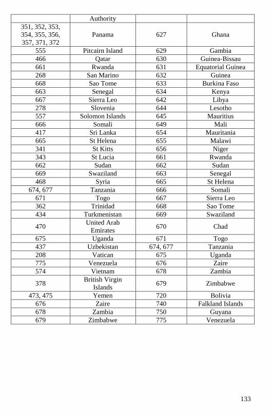
133
Authority
351, 352, 353,
354, 355, 356,
357, 371, 372
Panama 627 Ghana
555 Pitcairn Island 629 Gambia
466 Qatar 630 Guinea-Bissau
661 Rwanda 631 Equatorial Guinea
268 San Marino 632 Guinea
668 Sao Tome 633 Burkina Faso
663 Senegal 634 Kenya
667 Sierra Leo 642 Libya
278 Slovenia 644 Lesotho
557 Solomon Islands 645 Mauritius
666 Somali 649 Mali
417 Sri Lanka 654 Mauritania
665 St Helena 655 Malawi
341 St Kitts 656 Niger
343 St Lucia 661 Rwanda
662 Sudan 662 Sudan
669 Swaziland 663 Senegal
468 Syria 665 St Helena
674, 677 Tanzania 666 Somali
671 Togo 667 Sierra Leo
362 Trinidad 668 Sao Tome
434 Turkmenistan 669 Swaziland
470 United Arab
Emirates 670 Chad
675 Uganda 671 Togo
437 Uzbekistan 674, 677 Tanzania
208 Vatican 675 Uganda
775 Venezuela 676 Zaire
574 Vietnam 678 Zambia
378 British Virgin
Islands 679 Zimbabwe
473, 475 Yemen 720 Bolivia
676 Zaire 740 Falkland Islands
678 Zambia 750 Guyana
679 Zimbabwe 775 Venezuela
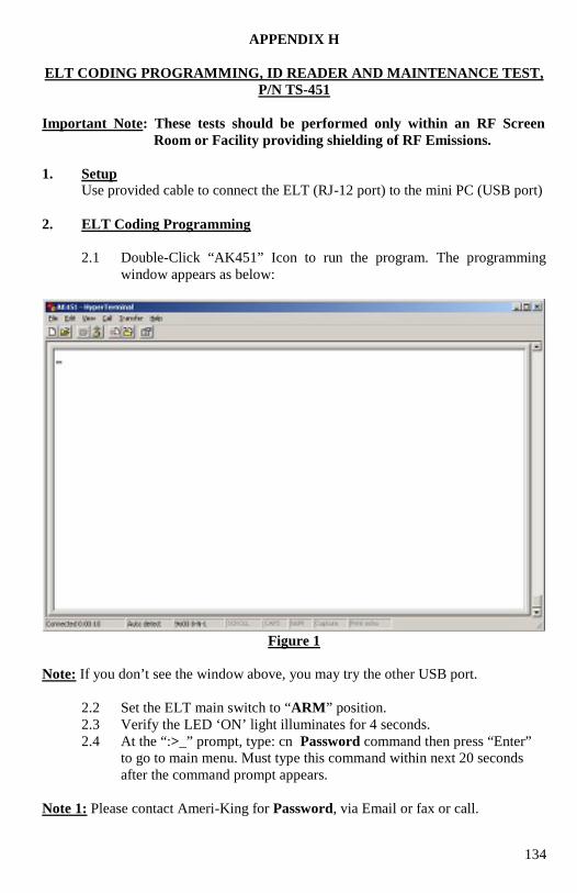
134
APPENDIX H
ELT CODING PROGRAMMING, ID READER AND MAINTENANCE TEST,
P/N TS-451
Important Note: These tests should be performed only within an RF Screen
Room or Facility providing shielding of RF Emissions.
1. Setup
Use provided cable to connect the ELT (RJ-12 port) to the mini PC (USB port)
2. ELT Coding Programming
2.1 Double-Click “AK451” Icon to run the program. The programming
window appears as below:
Figure 1
Note: If you don’t see the window above, you may try the other USB port.
2.2 Set the ELT main switch to “ARM” position.
2.3 Verify the LED ‘ON’ light illuminates for 4 seconds.
2.4 At the “:>_” prompt, type: cn Password command then press “Enter”
to go to main menu. Must type this command within next 20 seconds
after the command prompt appears.
Note 1: Please contact Ameri-King for Password, via Email or fax or call.
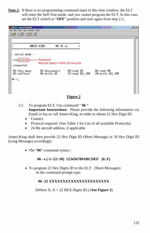
135
Note 2: If there is no programming command input in this time window, the ELT
will enter the Self-Test mode, and you cannot program the ELT. In this case,
set the ELT switch to “OFF” position and start again from step 2.2.
Figure 2
2.5 To program ELT: Use command “ 06 “
Important Instructions: Please provide the following information via
Email or fax or call Ameri-King, in order to obtain 22 Hex Digit ID:
Country
Protocol required (See Table 1 for List of all available Protocols)
24 Bit aircraft address, if applicable
Ameri-King shall then provide 22 Hex Digit ID (Short Message) or 30 Hex Digit ID
(Long Message) accordingly.
The “06” command syntax :
06 –s (-1/-22/-30) 123456789ABCDEF (0..F)
To program 22 Hex Digits ID to the ELT: (Short Messages)
At the command prompt type:
06 -22 XXXXXXXXXXXXXXXXXXXXXX
(Where X..X = 22 HEX Digits ID.) (See Figure 3)
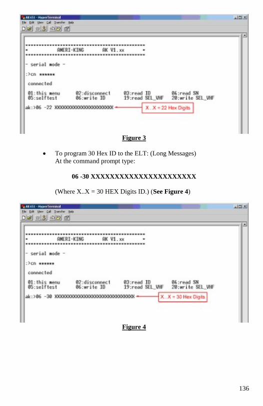
136
Figure 3
To program 30 Hex ID to the ELT: (Long Messages)
At the command prompt type:
06 -30 XXXXXXXXXXXXXXXXXXXXXX
(Where X..X = 30 HEX Digits ID.) (See Figure 4)
Figure 4
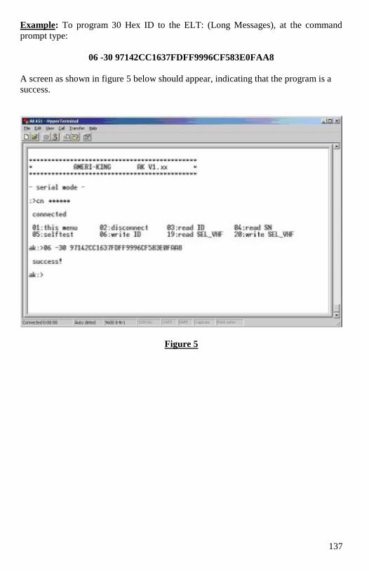
137
Example: To program 30 Hex ID to the ELT: (Long Messages), at the command
prompt type:
06 -30 97142CC1637FDFF9996CF583E0FAA8
A screen as shown in figure 5 below should appear, indicating that the program is a
success.
Figure 5
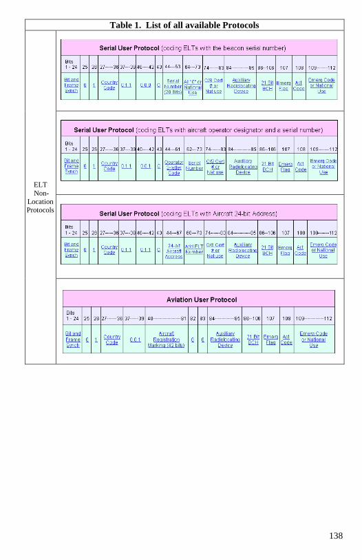
138
Table 1. List of all available Protocols
ELT
Non-
Location Protocols
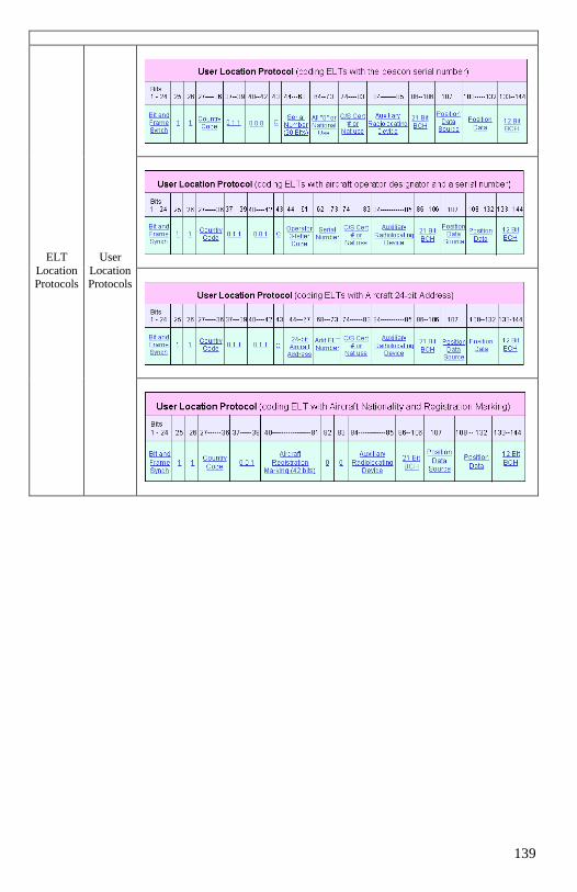
139
ELT
Location Protocols
User
Location Protocols
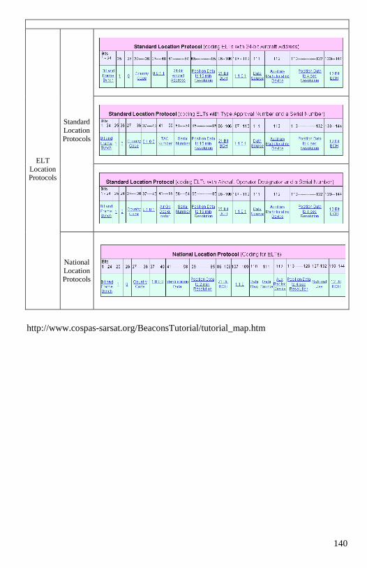
140
ELT
Location Protocols
Standard
Location Protocols
National
Location Protocols
http://www.cospas-sarsat.org/BeaconsTutorial/tutorial_map.htm
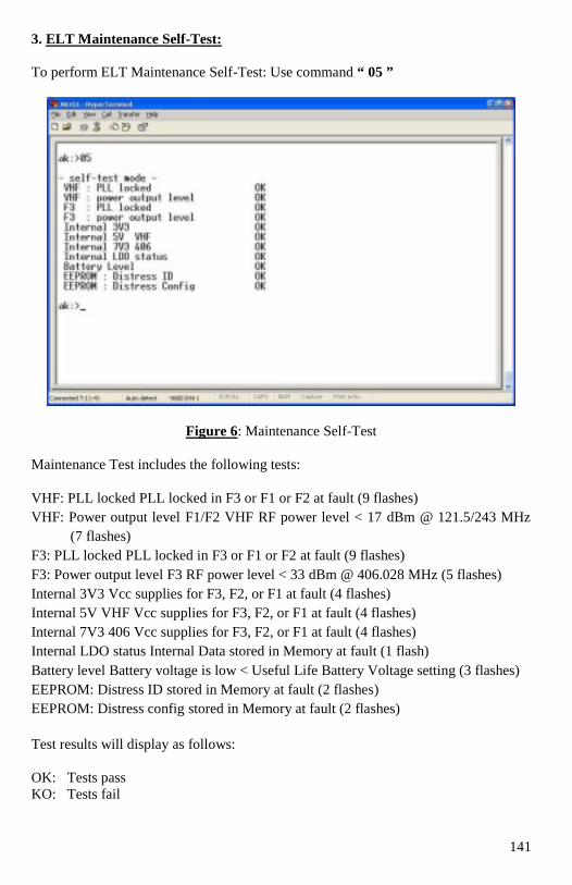
141
3. ELT Maintenance Self-Test:
To perform ELT Maintenance Self-Test: Use command “ 05 ”
Figure 6: Maintenance Self-Test
Maintenance Test includes the following tests:
VHF: PLL locked PLL locked in F3 or F1 or F2 at fault (9 flashes)
VHF: Power output level F1/F2 VHF RF power level < 17 dBm @ 121.5/243 MHz
(7 flashes)
F3: PLL locked PLL locked in F3 or F1 or F2 at fault (9 flashes)
F3: Power output level F3 RF power level < 33 dBm @ 406.028 MHz (5 flashes)
Internal 3V3 Vcc supplies for F3, F2, or F1 at fault (4 flashes)
Internal 5V VHF Vcc supplies for F3, F2, or F1 at fault (4 flashes)
Internal 7V3 406 Vcc supplies for F3, F2, or F1 at fault (4 flashes)
Internal LDO status Internal Data stored in Memory at fault (1 flash)
Battery level Battery voltage is low < Useful Life Battery Voltage setting (3 flashes)
EEPROM: Distress ID stored in Memory at fault (2 flashes)
EEPROM: Distress config stored in Memory at fault (2 flashes)
Test results will display as follows:
OK: Tests pass
KO: Tests fail
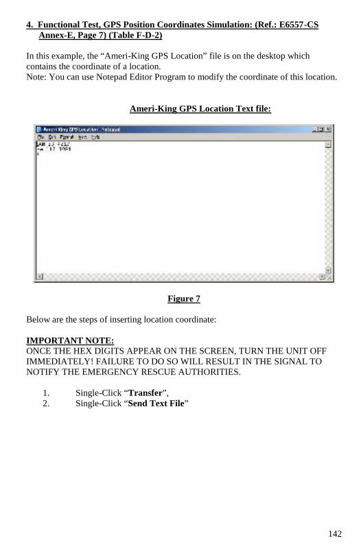
142
4. Functional Test, GPS Position Coordinates Simulation: (Ref.: E6557-CS
Annex-E, Page 7) (Table F-D-2)
In this example, the “Ameri-King GPS Location” file is on the desktop which
contains the coordinate of a location.
Note: You can use Notepad Editor Program to modify the coordinate of this location.
Ameri-King GPS Location Text file:
Figure 7
Below are the steps of inserting location coordinate:
IMPORTANT NOTE: ONCE THE HEX DIGITS APPEAR ON THE SCREEN, TURN THE UNIT OFF
IMMEDIATELY! FAILURE TO DO SO WILL RESULT IN THE SIGNAL TO
NOTIFY THE EMERGENCY RESCUE AUTHORITIES.
1. Single-Click “Transfer”,
2. Single-Click “Send Text File”
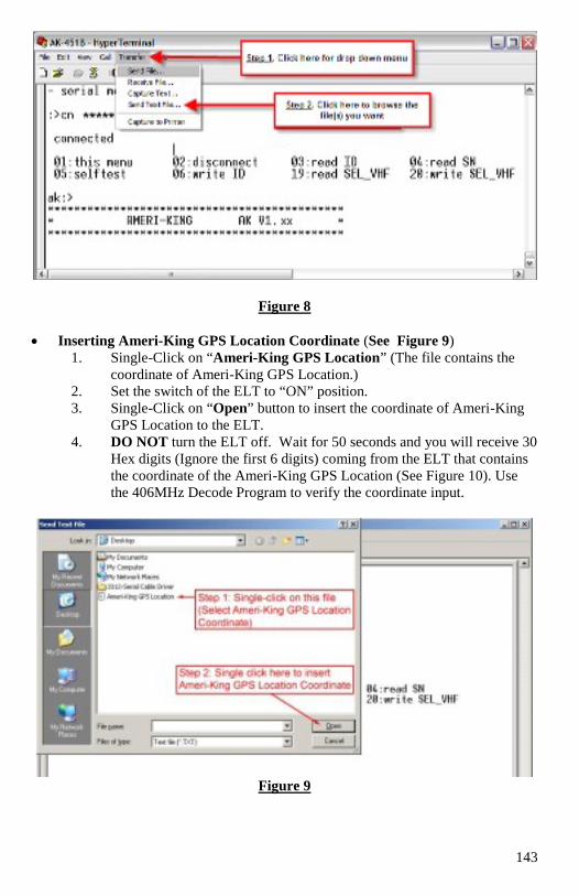
143
Figure 8
Inserting Ameri-King GPS Location Coordinate (See Figure 9)
1. Single-Click on “Ameri-King GPS Location” (The file contains the
coordinate of Ameri-King GPS Location.)
2. Set the switch of the ELT to “ON” position.
3. Single-Click on “Open” button to insert the coordinate of Ameri-King
GPS Location to the ELT.
4. DO NOT turn the ELT off. Wait for 50 seconds and you will receive 30
Hex digits (Ignore the first 6 digits) coming from the ELT that contains
the coordinate of the Ameri-King GPS Location (See Figure 10). Use
the 406MHz Decode Program to verify the coordinate input.
Figure 9
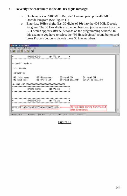
144
To verify the coordinate in the 30 Hex digits message:
o Double-click on “406MHz Decode” Icon to open up the 406MHz
Decode Program (See Figure 11)
o Enter last 30Hex digits (last 30 digits of 36) into the 406 MHz Decode
Program. The 30 Hex digits are the numbers you just have seen from the
ELT which appears after 50 seconds on the programming window. In
this example you have to select the “30 Hexadecimal” round button and
press Process button to decode these 30 Hex numbers.
Figure 10
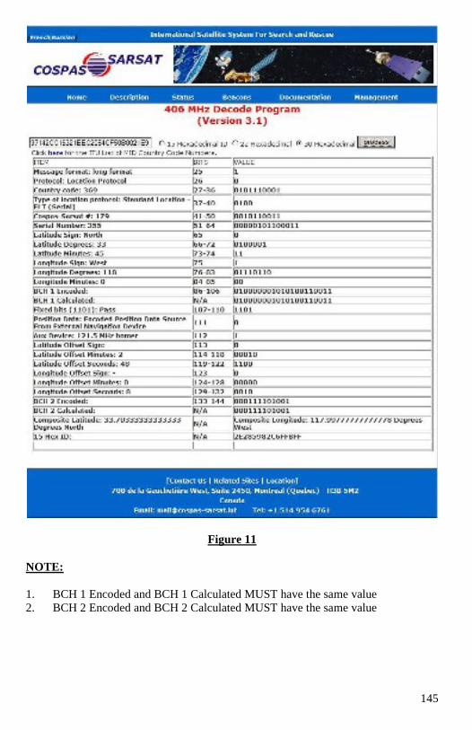
145
Figure 11
NOTE:
1. BCH 1 Encoded and BCH 1 Calculated MUST have the same value
2. BCH 2 Encoded and BCH 2 Calculated MUST have the same value
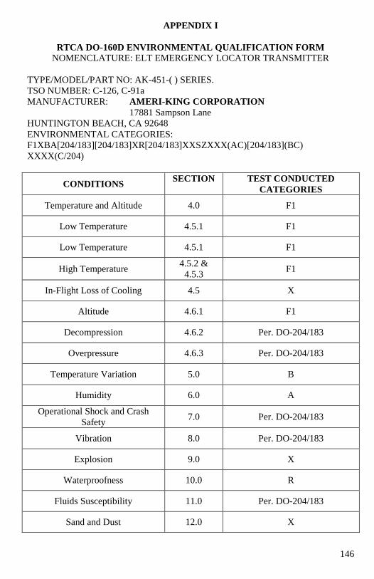
146
APPENDIX I
RTCA DO-160D ENVIRONMENTAL QUALIFICATION FORM
NOMENCLATURE: ELT EMERGENCY LOCATOR TRANSMITTER
TYPE/MODEL/PART NO: AK-451-( ) SERIES.
TSO NUMBER: C-126, C-91a
MANUFACTURER: AMERI-KING CORPORATION
17881 Sampson Lane
HUNTINGTON BEACH, CA 92648
ENVIRONMENTAL CATEGORIES:
F1XBA[204/183][204/183]XR[204/183]XXSZXXX(AC)[204/183](BC)
XXXX(C/204)
CONDITIONS SECTION TEST CONDUCTED
CATEGORIES
Temperature and Altitude 4.0 F1
Low Temperature 4.5.1 F1
Low Temperature 4.5.1 F1
High Temperature 4.5.2 &
4.5.3 F1
In-Flight Loss of Cooling 4.5 X
Altitude 4.6.1 F1
Decompression 4.6.2 Per. DO-204/183
Overpressure 4.6.3 Per. DO-204/183
Temperature Variation 5.0 B
Humidity 6.0 A
Operational Shock and Crash
Safety 7.0 Per. DO-204/183
Vibration 8.0 Per. DO-204/183
Explosion 9.0 X
Waterproofness 10.0 R
Fluids Susceptibility 11.0 Per. DO-204/183
Sand and Dust 12.0 X
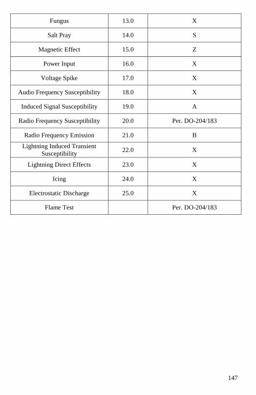
147
Fungus 13.0 X
Salt Pray 14.0 S
Magnetic Effect 15.0 Z
Power Input 16.0 X
Voltage Spike 17.0 X
Audio Frequency Susceptibility 18.0 X
Induced Signal Susceptibility 19.0 A
Radio Frequency Susceptibility 20.0 Per. DO-204/183
Radio Frequency Emission 21.0 B
Lightning Induced Transient
Susceptibility 22.0 X
Lightning Direct Effects 23.0 X
Icing 24.0 X
Electrostatic Discharge 25.0 X
Flame Test Per. DO-204/183
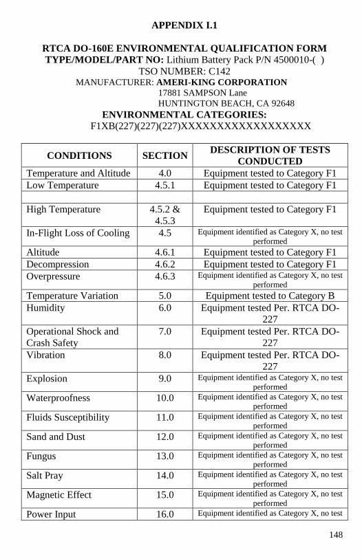
148
APPENDIX I.1
RTCA DO-160E ENVIRONMENTAL QUALIFICATION FORM
TYPE/MODEL/PART NO: Lithium Battery Pack P/N 4500010-( )
TSO NUMBER: C142 MANUFACTURER: AMERI-KING CORPORATION
17881 SAMPSON Lane
HUNTINGTON BEACH, CA 92648
ENVIRONMENTAL CATEGORIES: F1XB(227)(227)(227)XXXXXXXXXXXXXXXXXX
CONDITIONS SECTION DESCRIPTION OF TESTS
CONDUCTED
Temperature and Altitude 4.0 Equipment tested to Category F1
Low Temperature 4.5.1 Equipment tested to Category F1
High Temperature 4.5.2 &
4.5.3
Equipment tested to Category F1
In-Flight Loss of Cooling 4.5 Equipment identified as Category X, no test
performed
Altitude 4.6.1 Equipment tested to Category F1
Decompression 4.6.2 Equipment tested to Category F1
Overpressure 4.6.3 Equipment identified as Category X, no test
performed
Temperature Variation 5.0 Equipment tested to Category B
Humidity 6.0 Equipment tested Per. RTCA DO-
227
Operational Shock and
Crash Safety
7.0 Equipment tested Per. RTCA DO-
227
Vibration 8.0 Equipment tested Per. RTCA DO-
227
Explosion 9.0 Equipment identified as Category X, no test
performed
Waterproofness 10.0 Equipment identified as Category X, no test
performed
Fluids Susceptibility 11.0 Equipment identified as Category X, no test
performed
Sand and Dust 12.0 Equipment identified as Category X, no test
performed
Fungus 13.0 Equipment identified as Category X, no test
performed
Salt Pray 14.0 Equipment identified as Category X, no test
performed
Magnetic Effect 15.0 Equipment identified as Category X, no test
performed
Power Input 16.0 Equipment identified as Category X, no test
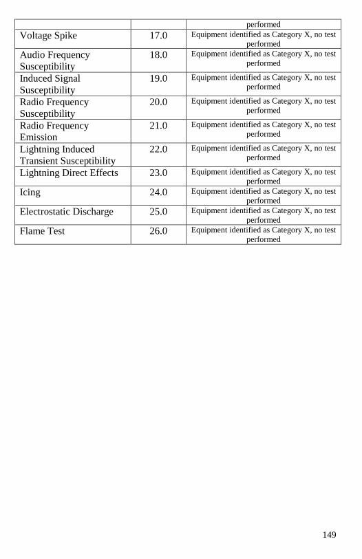
149
performed
Voltage Spike 17.0 Equipment identified as Category X, no test
performed
Audio Frequency
Susceptibility
18.0 Equipment identified as Category X, no test
performed
Induced Signal
Susceptibility
19.0 Equipment identified as Category X, no test
performed
Radio Frequency
Susceptibility
20.0 Equipment identified as Category X, no test
performed
Radio Frequency
Emission
21.0 Equipment identified as Category X, no test
performed
Lightning Induced
Transient Susceptibility
22.0 Equipment identified as Category X, no test
performed
Lightning Direct Effects 23.0 Equipment identified as Category X, no test
performed
Icing 24.0 Equipment identified as Category X, no test
performed
Electrostatic Discharge 25.0 Equipment identified as Category X, no test
performed
Flame Test 26.0 Equipment identified as Category X, no test
performed
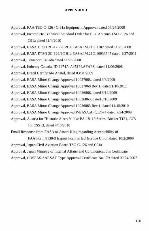
150
APPENDIX J
Approval, FAA TSO C-126 / C-91a Equipment Approval dated 07/24/2008
Approval, Incomplete Technical Standard Order for ELT Antenna TSO C126 and
C91a dated 11/4/2010
Approval, EASA ETSO 2C-126/2C-91a EASA.IM.21O.1102 dated 11/20/2008
Approval, EASA ETSO 2C-126/2C-91a EASA.IM.21O.10033545 dated 1/27/2011
Approval, Transport Canada dated 11/26/2008
Approval, Industry Canada, ID 2474A-A451PLAFAPS, dated 11/06/2008
Approval, Brazil Certificado Anatel, dated 03/31/2009
Approval, EASA Minor Change Approval 10027068, dated 9/3/2009
Approval, EASA Minor Change Approval 10027068 Rev 1, dated 1/10/2011
Approval, EASA Minor Change Approval 10026866, dated 8/18/2009
Approval, EASA Minor Change Approval 10026863, dated 8/18/2009
Approval, EASA Minor Change Approval 10026863 Rev 1, dated 11/15/2010
Approval, EASA Minor Change Approval P-EASA.A.C.12674 dated 7/24/2009
Approval, Austria for "Historic Aircraft" like PA-18, 19 Series, Bücker T131, JOB
15, CSS13, dated 4/16/2010
Email Response from EASA to Ameri-King regarding Acceptability of
FAA Form 8130-3 Export Form in EU Europe Union dated 10/2/2009
Approval, Japan Civil Aviation Board TSO C-126 and C91a
Approval, Japan Ministry of Internal Affairs and Communications Certificate
Approval, COSPAS-SARSAT Type Approval Certificate No.179 dated 09/24/2007
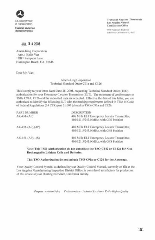
151
152
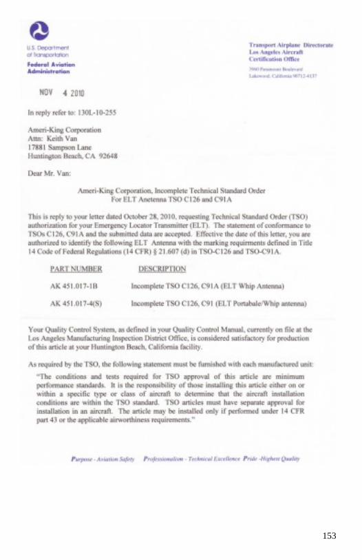
153
154
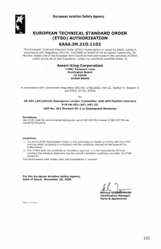
155
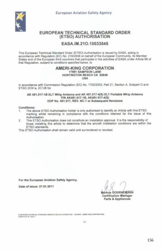
156

157

158
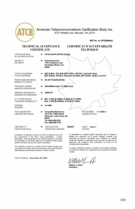
159
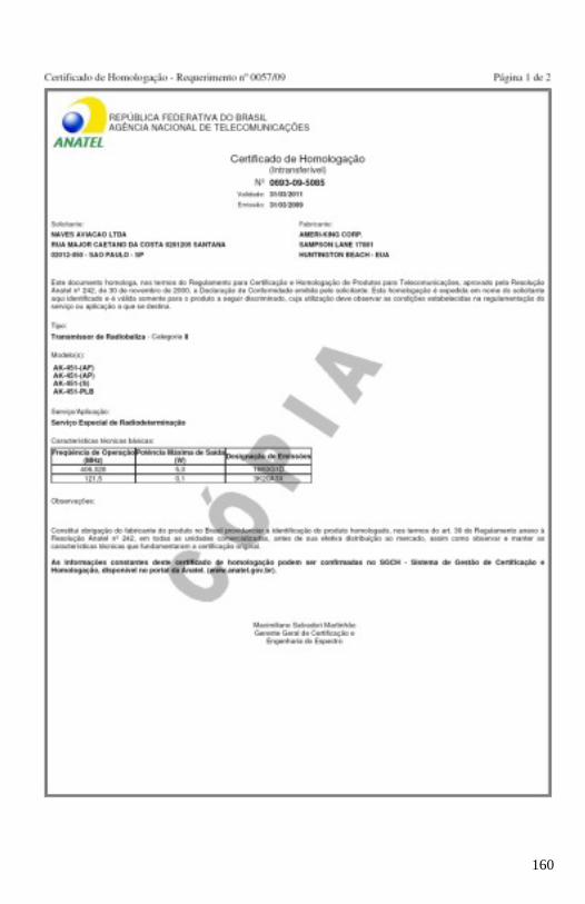
160

161
162
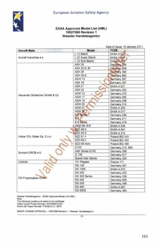
163
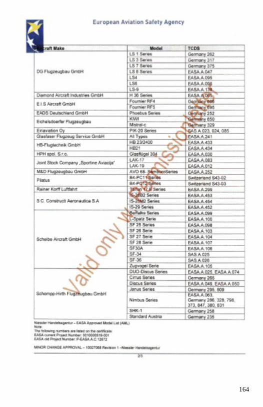
164
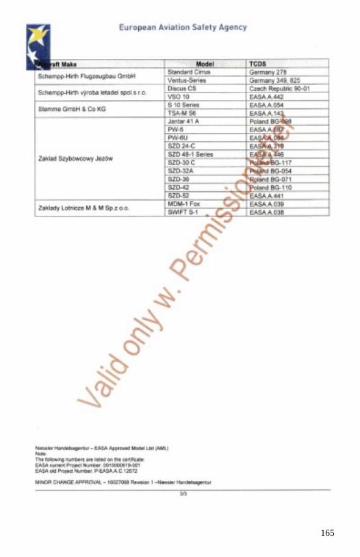
165
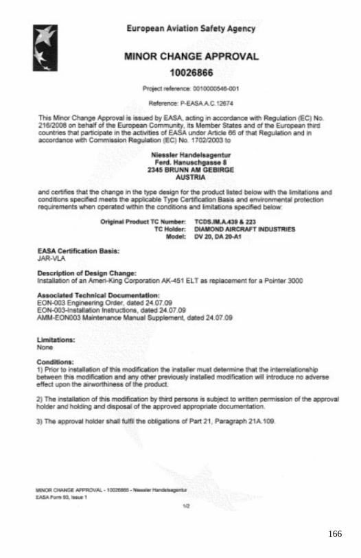
166
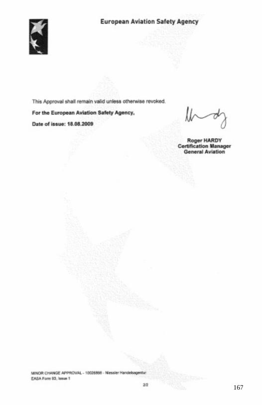
167
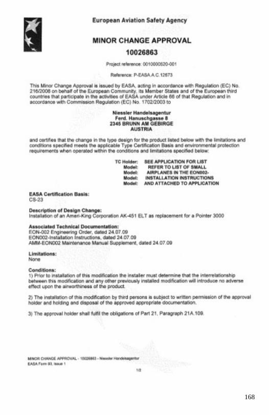
168

169
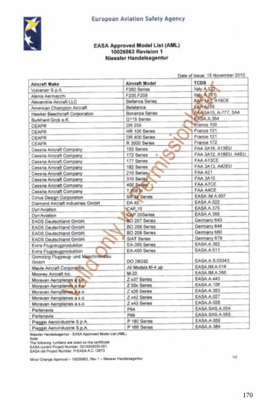
170
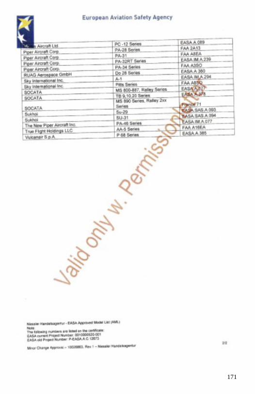
171
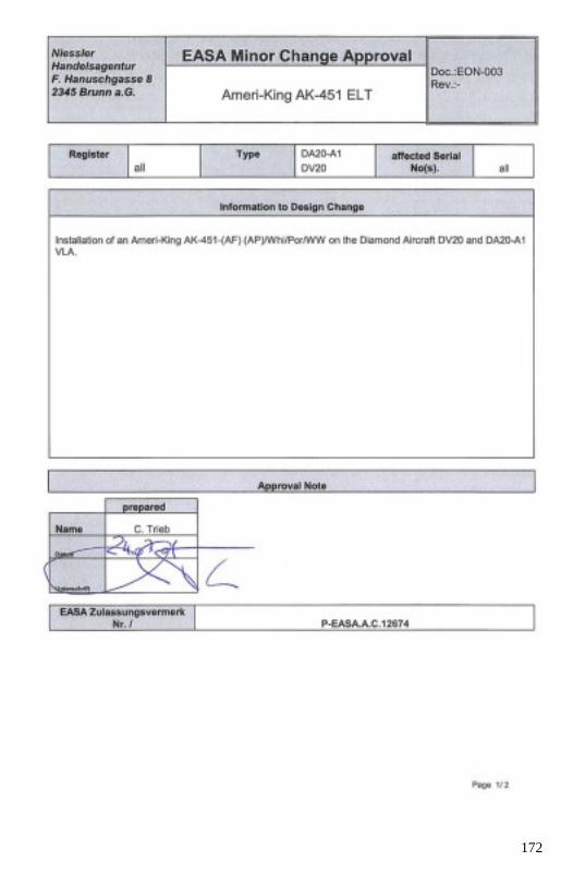
172
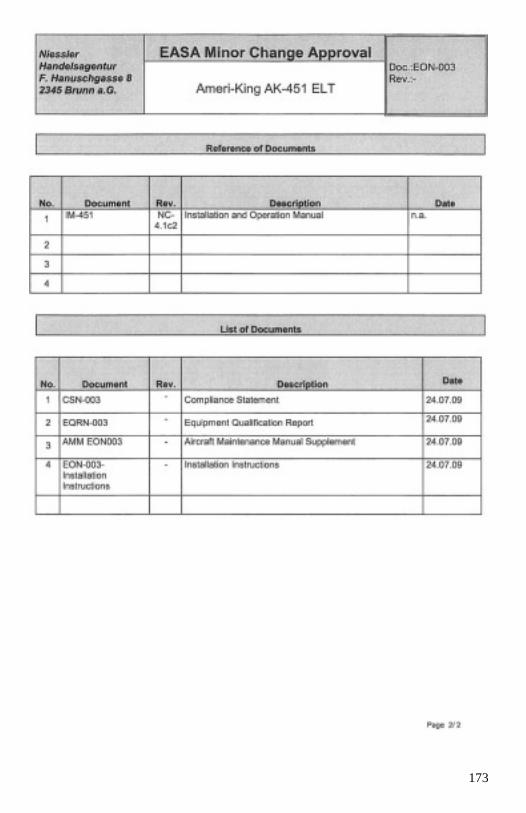
173
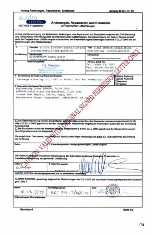
174
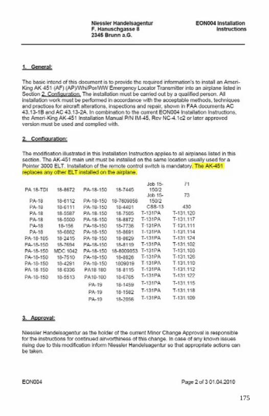
175

176
177
178
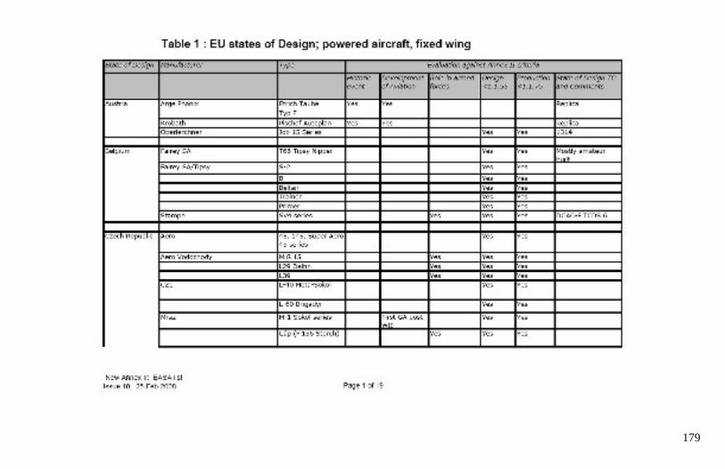
179
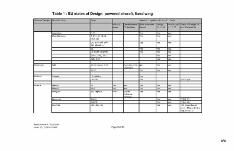
180
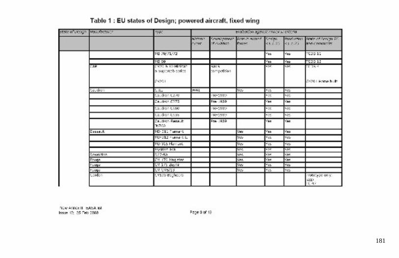
181
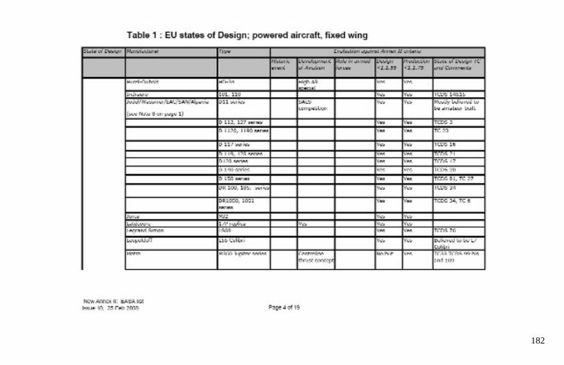
182
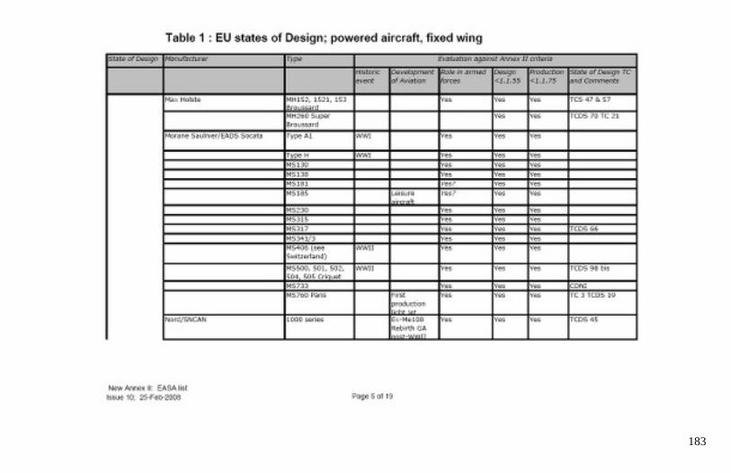
183
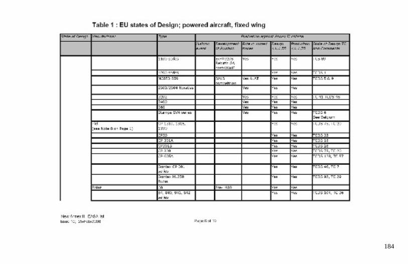
184
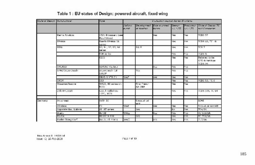
185
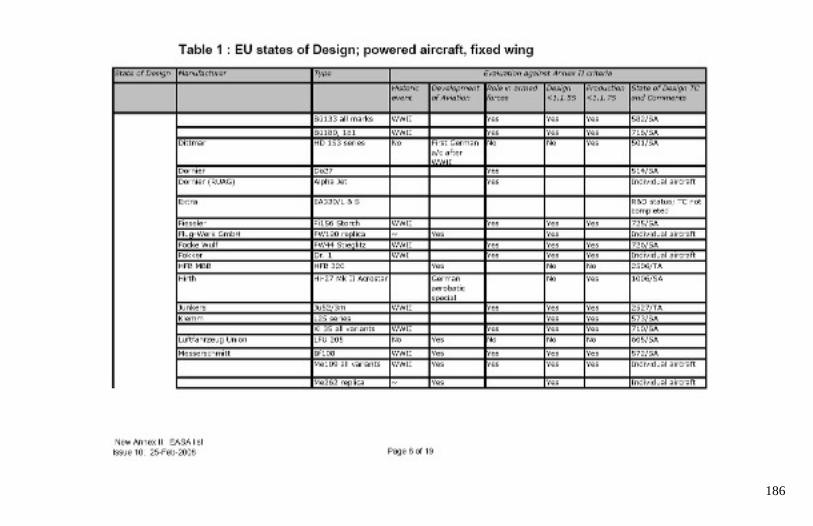
186
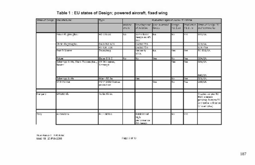
187
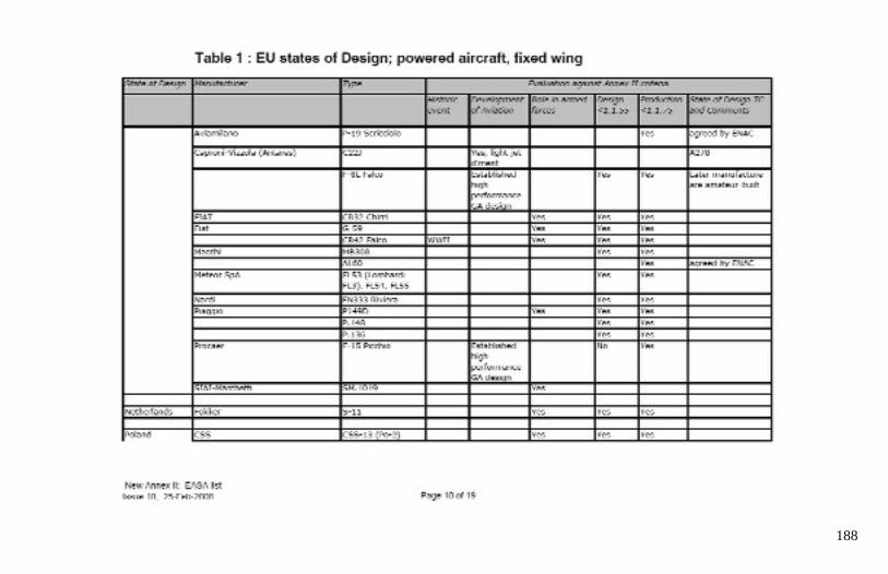
188
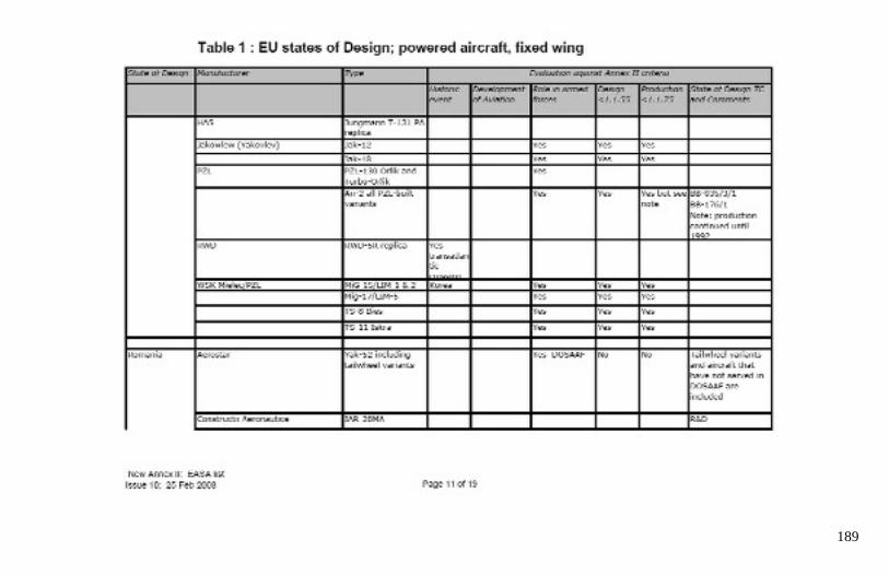
189
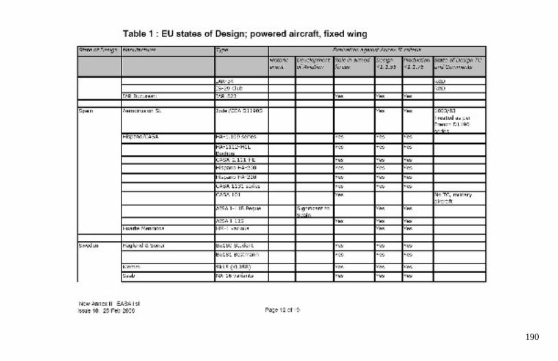
190
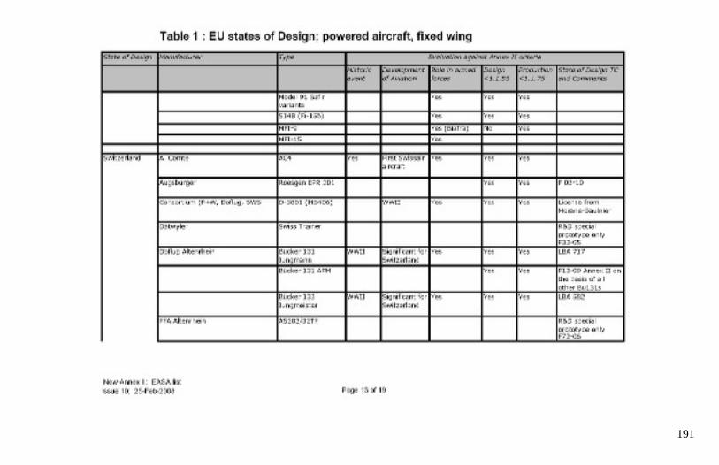
191
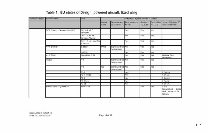
192
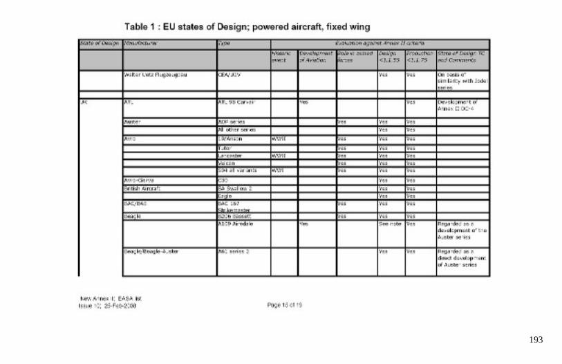
193
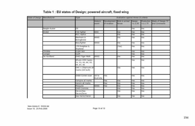
194
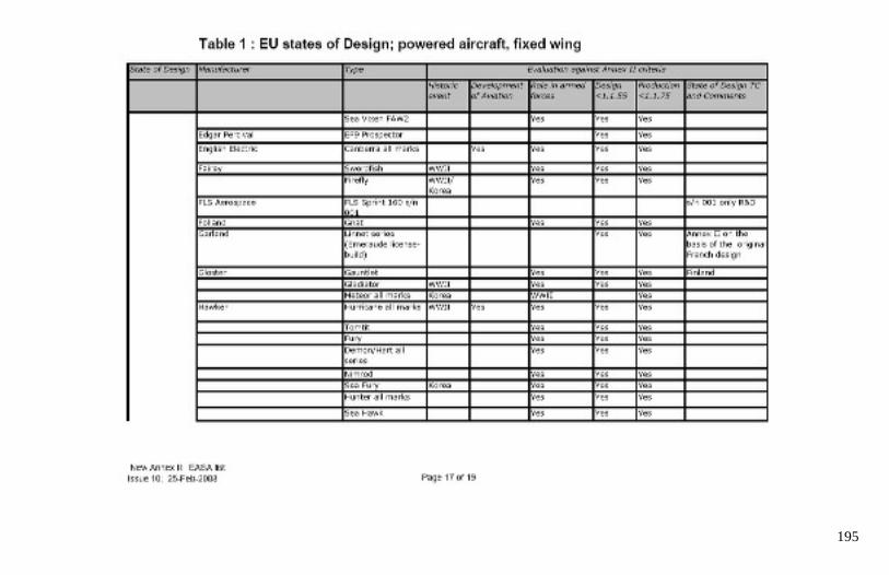
195
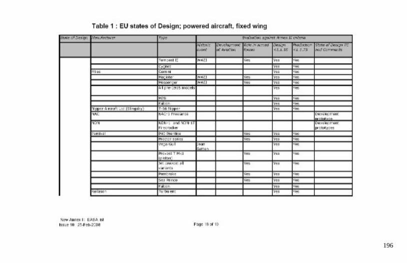
196
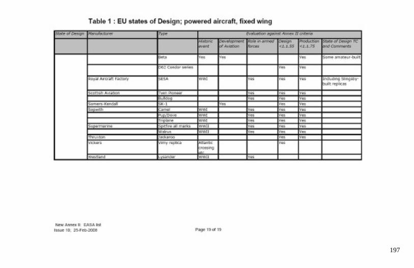
197

198
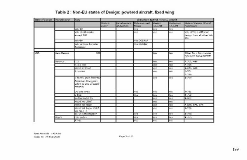
199
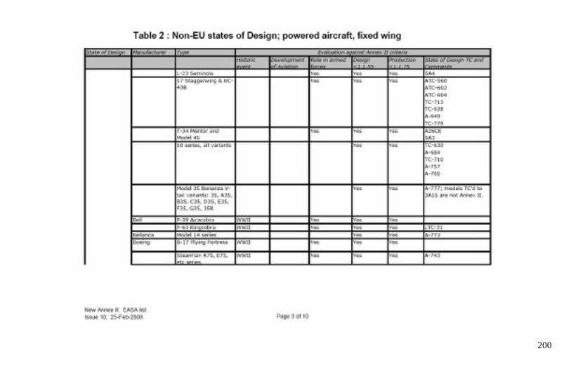
200

201

202
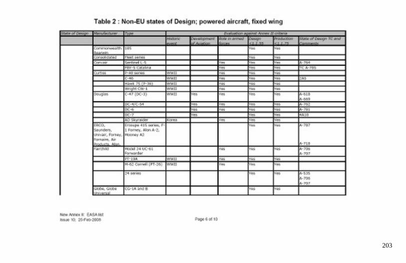
203
204
205
206
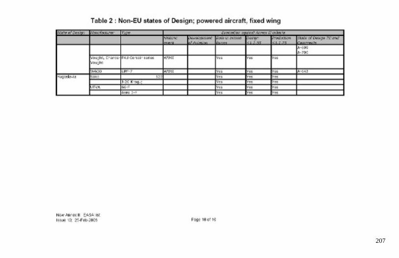
207
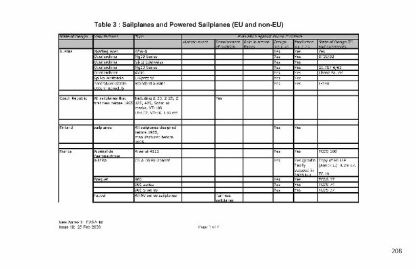
208
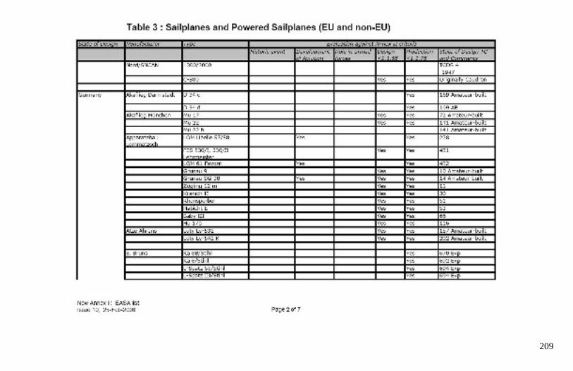
209
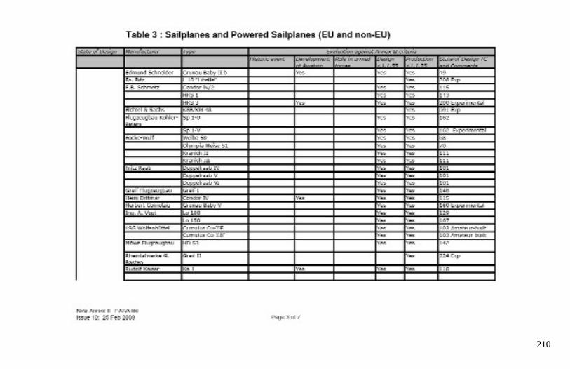
210
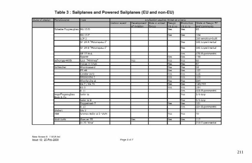
211
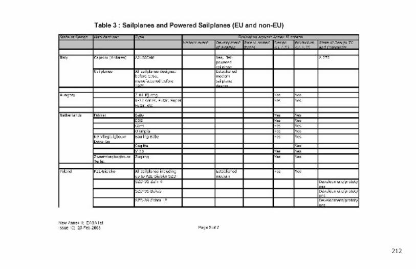
212
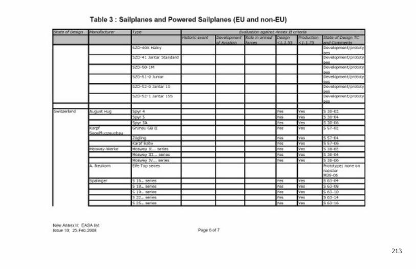
213
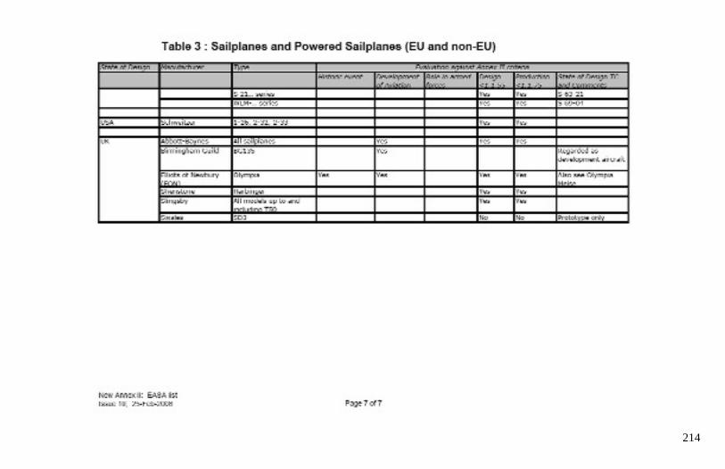
214
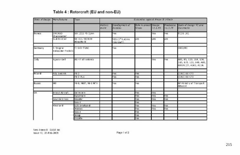
215
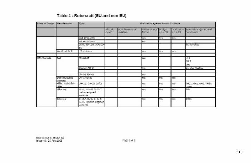
216
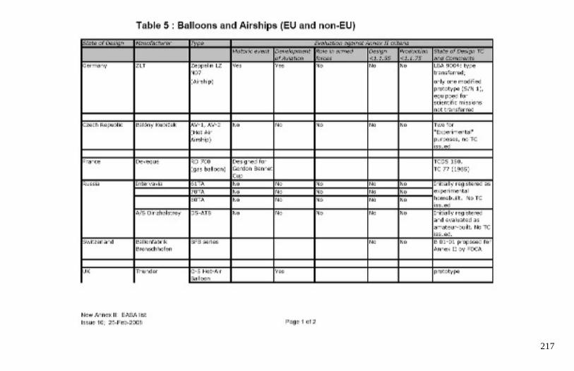
217
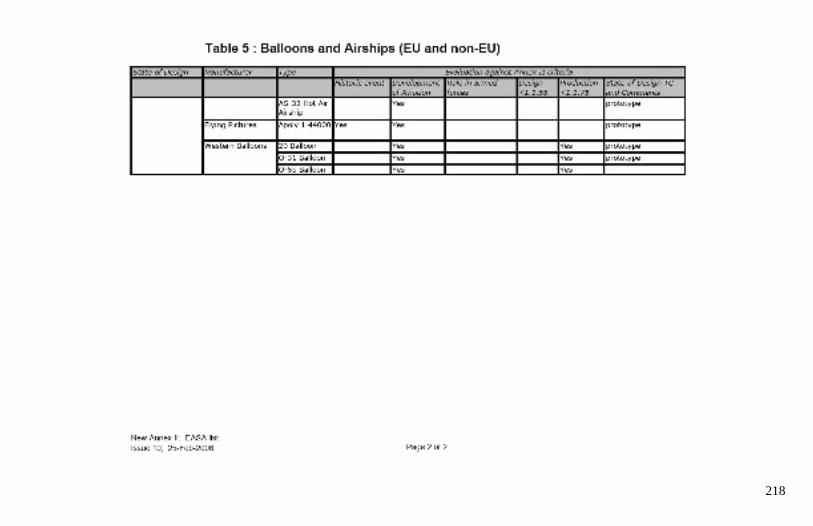
218
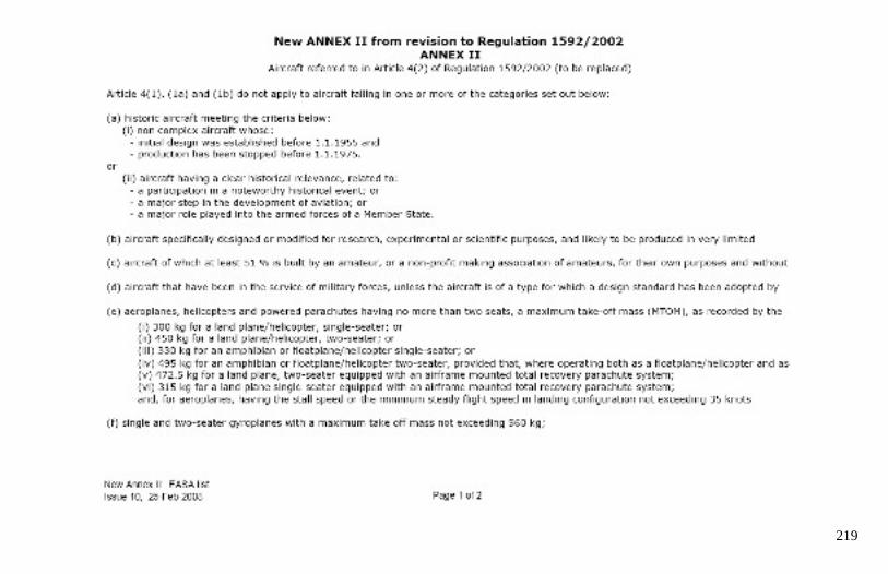
219
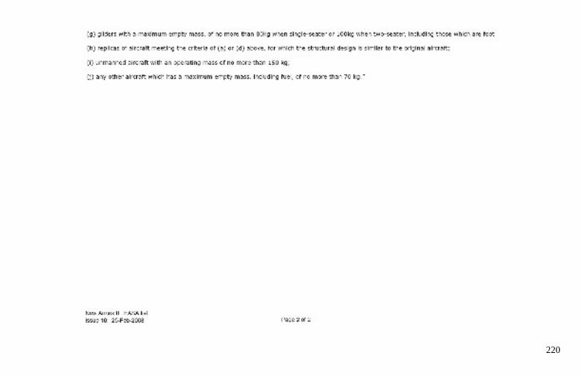
220

221
Email Response from EASA to Ameri-King regarding
Acceptability of FAA Form 8130-3 Export Form in EU Europe Union
From: Ameri-King Corporation
To: EASA European Aviation Safety Agency
Attn: Mr. Runge Friedhelm
Subject: Request for Guideline, Acceptability of FAA Form 8130-3 Export Form in EU
Application: Authorized Release Certificate, FAA Form 8130-3, New TSO Article
Date: October 2, 2009
Dear Runge:
Please advise if the FAA form 8130-3 export form issued to any of 27 EU countries,
(equivalent to EASA form 1), is acceptable in all of the 27 European countries ??
i.e. Separate 8130-3 export form for each of the 27 countries is not necessary.
Member states: 27 countries: Austria, Belgium, Bulgaria, Cyprus, Czech Republic,
Denmark, Estonia, Finland, France, Germany, Greece, Hungary, Ireland, Italy, Latvia,
Lithuania, Luxembourg, Malta, Netherlands, Poland, Portugal, Romania, Slovakia,
Slovenia, Spain, Sweden, UK; note - Canary Islands (Spain), Azores and Madeira
(Portugal), French Guiana, Guadeloupe, Martinique, and Reunion (France) are
sometimes listed separately even though they are legally a part of Spain, Portugal, and
France.
Thank you for your prompt response.
Keith Van
Engineering Manager
Ameri-King Corp.
17881 Sampson Lane, Huntington Beach, CA 92648, USA
Phone (714) 842-8555 Fax (714) 842-4235
[email protected] www.ameri-king.com
__________________________________________

222
From: Runge Friedhelm <[email protected]>
To: Keith Van <[email protected]>
Date: Wed, Oct 7, 2009 4:44 am
RE: Request for Guideline Acceptability of FAA Form 8130-3 Export Form in EU
Dear Keith,
The form 8130-3 is filled once by you for each unit or each lot produced. In
accordance with the old bilateral agreements it will be accepted in all EU member
states including the specific areas having the specific tax status like Canary Island,
Norway, Switzerland, and Iceland.
As the import country is not mentioned at all on the certificate it is issued once by you
when manufacturing the unit, like our Form One. We assume that the 8130-3 will be
accepted in all the named countries based on the grandfathered existing bilateral
agreement with the main players in EU and the US. Due to the fact that the new
bilateral is not in place we cannot guarantee that, especially as some countries seem
not to be accepted by the US side to be eligible to export into the US.
Unless you state “FOR DOMESTIC SHIPMENTS ONLY,” on the Form 8130-3 the
Form issued at the end of the production process is intended to be used for import into
the EU system as well. In general the form is issued after production and kept for the
life time of the unit.
Please come back to me if there are complaints from the European customers.
Best regards
Friedhelm
__________________________________
EASA European Aviation Safety Agency
Parts and Appliances Section
Friedhelm RUNGE
+49 221 89990 4084
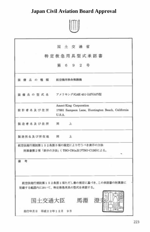
223
Japan Civil Aviation Board Approval
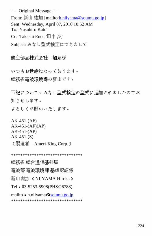
224
-----Original Message-----
From: 新山 紘加 [mailto:[email protected]]
Sent: Wednesday, April 07, 2010 10:52 AM
To: 'Yasuhiro Kato'
Cc: 'Takashi Eno'; '田中 友 '
Subject: みなし型式検定につきまして
航空部品株式会社 加藤様
いつもお世話になっております。
総務省電波環境課の新山です。
下記について、みなし型式検定の型式 に追加されましたのでお
知らせします。
よろしくお願いいたします。
AK-451-(AF)
AK-451-(AF)(AP)
AK-451-(AP)
AK-451-(S)
(製造者 Ameri-King Corp. )
*******************************
総務省 総合通信基盤局
電波部 電波環境課 基準認証係
新山 紘加( NIIYAMA Hiroka )
Tel : 03-5253-5908(PHS:26788)
mailto : h.niiyama @ soumu.go.jp
*******************************
225

226
This page is left blank on purpose.
227
228
229
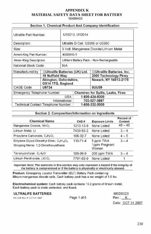
230
APPENDIX K
MATERIAL SAFETY DATA SHEET FOR BATTERY
231
232
233
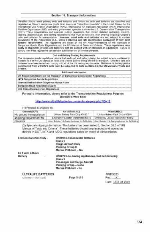
234
235
236
237
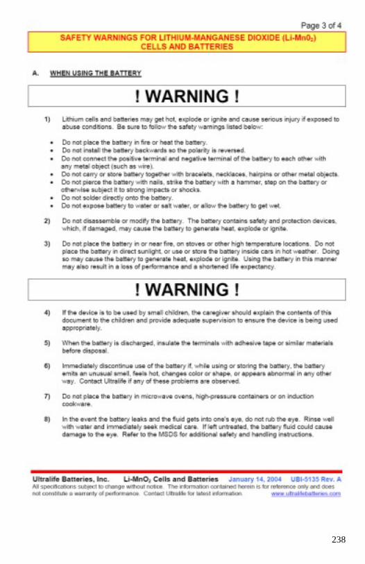
238
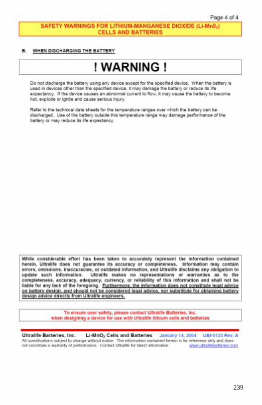
239

240
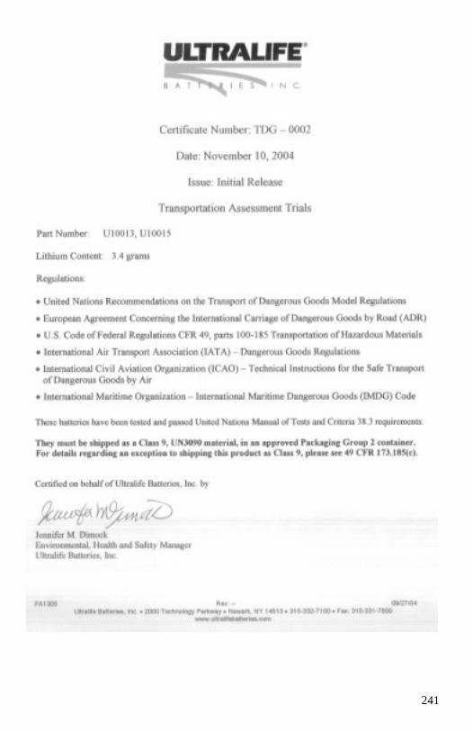
241