Embed Size (px)
Citation preview

DeltaPoint ™
Installation and Operation Manual 12 GPM Water Saver
AC Unit
ROCON LLC 1755 East Nine Mile Road PO Box 249 Hazel Park, MI 48030-0249 TEL (248) 542-9635 FAX (248) 398-4274 Website: http://www.flowmeters.com

ROCON LLC
DPLAC MAN 01-14-09.PDF 2
ROCON LLC
TABLE OF CONTENTS
TABLE OF CONTENTS............................................................................................................................2 PROPRIETARY NOTICE..........................................................................................................................3 USING THIS MANUAL..............................................................................................................................4
Nameplate Example ..............................................................................................................................4 SPECIFICATIONS – 12 GPM (45 LPM) UNIT..........................................................................................5
Pressure Drop Data...............................................................................................................................5 HOW VORTEX SHEDDING FLOW METER WORKS..............................................................................6 HOW THE DELTAPOINT MONITORS COOLING WATER IN THE ROBOTICS CELL ..........................7
Indicator Lights ......................................................................................................................................8 Keypad...................................................................................................................................................9
INSTALLATION.......................................................................................................................................10 SETUP AND CONFIGURATION ............................................................................................................11
START UP...........................................................................................................................................11 START-UP TEST CYCLE ...................................................................................................................12 FACTORY SETPOINTS......................................................................................................................12
LCD Screen .....................................................................................................................................13 USER MENU...........................................................................................................................................14
Set Flow OK ........................................................................................................................................14 Set Min Flow........................................................................................................................................15 Set Leak Rate......................................................................................................................................15 Set Over Temperature.........................................................................................................................16 Set Response Time.............................................................................................................................16 Restart Delay.......................................................................................................................................17 Engineering Units ................................................................................................................................18 Setting System Clock ..........................................................................................................................18
MAINTENANCE ......................................................................................................................................19 Shut-Off Valve .....................................................................................................................................19 Check Valve ........................................................................................................................................19 Cleaning ..............................................................................................................................................19 Note .....................................................................................................................................................19
TROUBLESHOOTING............................................................................................................................20 DIMENSIONS .........................................................................................................................................24 MODEL CODES......................................................................................................................................26 APPENDIX ..............................................................................................................................................27
Check Valve Specifications .................................................................................................................27 Shut-Off Valve Specifications..............................................................................................................27
RMA NOTICE RETURN MATERIAL AUTHORIZATION.....................................................................28 RMA FORM.............................................................................................................................................29 ROCON / DELTAPOINT WARRANTY ...................................................................................................30

ROCON LLC
DPLAC MAN 01-14-09.PDF 3
ROCON LLC
PROPRIETARY NOTICE The information contained in this publication is derived in part from proprietary and patented data. This information has been prepared for the express purpose of assisting in installation, operation, and maintenance of the instruments described herein. Publication of this information does not convey any rights of use or reproduction other than in connection with the installation, operation and maintenance of the equipment described herein. Universal Flow Monitors, Inc. and Rocon LLC reserve the right to change the information contained in this publication at any time and without prior notice.
ROCON LLC
DPLAC MAN 01-14-09.PDF 4
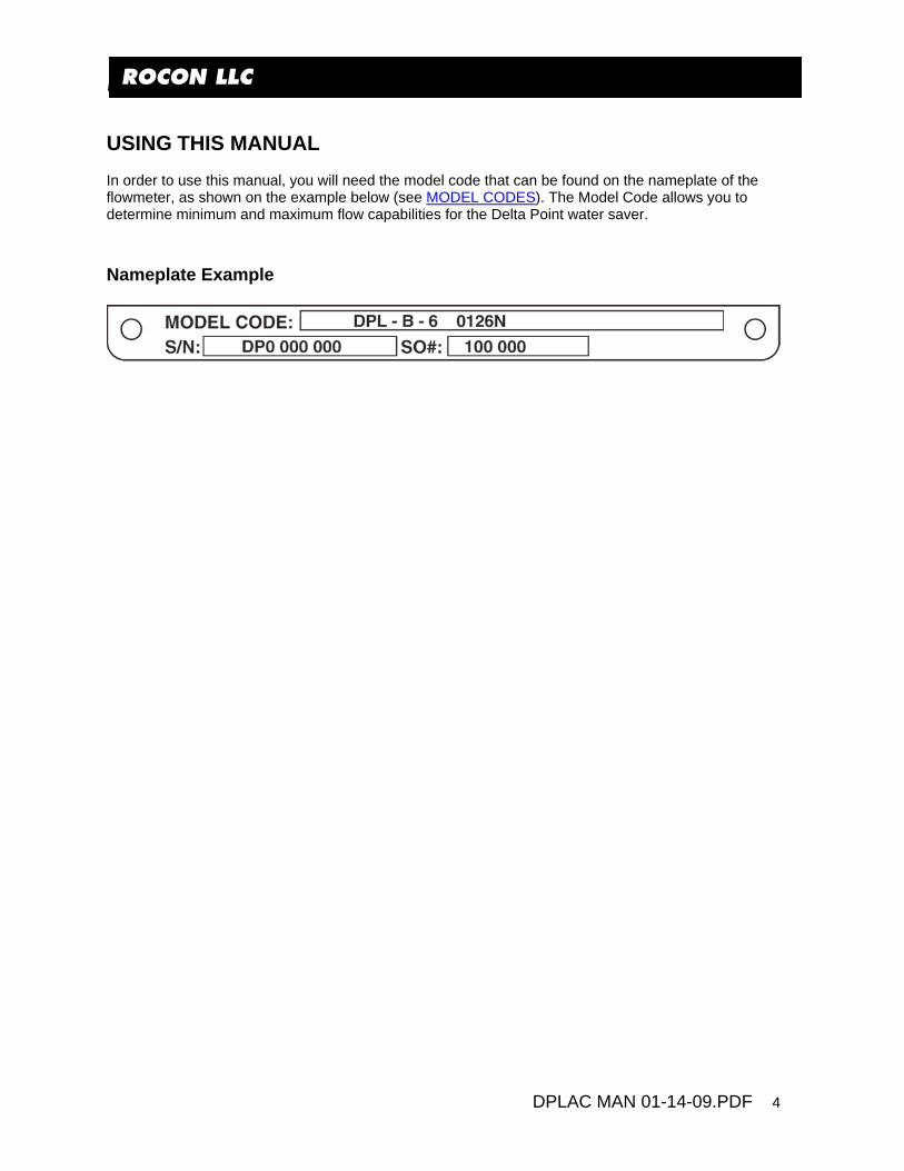
ROCON LLC USING THIS MANUAL In order to use this manual, you will need the model code that can be found on the nameplate of the flowmeter, as shown on the example below (see MODEL CODES). The Model Code allows you to determine minimum and maximum flow capabilities for the Delta Point water saver. Nameplate Example
ROCON LLC
DPLAC MAN 01-14-09.PDF 5
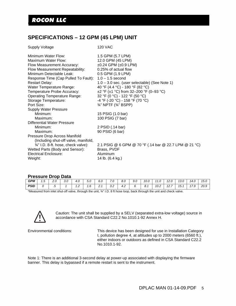
ROCON LLC SPECIFICATIONS – 12 GPM (45 LPM) UNIT Supply Voltage 120 VAC Minimum Water Flow: 1.5 GPM (5.7 LPM) Maximum Water Flow: 12.0 GPM (45 LPM) Flow Measurement Accuracy: ±0.24 GPM (±0.9 LPM) Flow Measurement Repeatability: 0.25% of actual flow Minimum Detectable Leak: 0.5 GPM (1.9 LPM) Response Time (Cap Pulled To Fault): 1.0 – 1.5 second Restart Delay: 1.0 – 3.0 sec. (user selectable) (See Note 1) Water Temperature Range: 40 °F (4.4 °C) - 180 °F (82 °C) Temperature Probe Accuracy: ±2 °F (±1 °C) from 32–200 °F (0–93 °C) Operating Temperature Range: 32 °F (0 °C) - 122 °F (50 °C) Storage Temperature: -4 °F (-20 °C) - 158 °F (70 °C) Port Size: ¾” NPTF (¾” BSPP) Supply Water Pressure
Minimum: 15 PSIG (1.0 bar) Maximum: 100 PSIG (7 bar)
Differential Water Pressure Minimum: 2 PSID (.14 bar) Maximum: 90 PSID (6 bar)
Pressure Drop Across Manifold (Including shut-off valve, manifold, ¾” I.D. 8-ft. hose, check valve): 2.1 PSIG @ 6 GPM @ 70 °F (.14 bar @ 22.7 LPM @ 21 °C)
Wetted Parts (Body and Sensor): Brass, PVDF Electrical Enclosure: Aluminum Weight: 14 lb. (6.4 kg.) Pressure Drop Data GPM 1.5 2.0 3.0 4.0 5.0 6.0 7.0 8.0 9.0 10.0 11.0 12.0 13.0 14.0 15.0 PSID 0 .5 1 1.2 1.6 2.1 3.2 4.2 6 8.1 10.2 12.7 15.1 17.9 20.9
*Measured from inlet shut-off valve, through the unit, ¾” I.D. 8 ft hose loop, back through the unit and check valve.
Caution: The unit shall be supplied by a SELV (separated extra-low voltage) source in accordance with CSA Standard C22.2 No.1010.1-92 Annex H.
Environmental conditions: This device has been designed for use in Installation Category
I, pollution degree 4, at altitudes up to 2000 meters (6560 ft.), either indoors or outdoors as defined in CSA Standard C22.2 No.1010.1-92.
Note 1: There is an additional 3-second delay at power-up associated with displaying the firmware banner. This delay is bypassed if a remote restart is sent to the instrument.

ROCON LLC
DPLAC MAN 01-14-09.PDF 6
ROCON LLC HOW VORTEX SHEDDING FLOW METER WORKS
When fluid passes by a bluff, oscillations occur. Examples of these oscillations in nature include the swirls produced downstream of a rock in a rapidly flowing river, or the waving of a flag in the wind with the bluff being the flag pole. DeltaPoint Unit Supply Water Leg example above: The fluid strikes a bluff body (A), generating vortices (B) (eddies) that move downstream. The vortices form alternately, from one side to the other. A piezoelectric sensor housed in a sensor tube (C) directly downstream of the bluff senses the pressure zones created by the vortices. The sensor generates a frequency directly proportional to the vortices (flow). The pulses are then measured by the microprocessor. Each DeltaPoint Unit has two vortex shedding flow meters. One flow meter monitors the supply path, and the other flow meter monitors the return path along with the temperature probe. PLEASE NOTE: Bluff / Sensors not effected by dirty water.
ROCON LLC
DPLAC MAN 01-14-09.PDF 7
ROCON LLC HOW THE DELTAPOINT MONITORS COOLING WATER IN THE ROBOTICS CELL Each DeltaPoint unit has two vortex shedding flow meters. One flow meter monitors the supply path, and the other flow meter monitors the return leg. The fluid strikes a bluff body, generating vortices (eddies) that move downstream. The vortices form alternately, from one side to the other. A piezoelectric sensor housed in a sensor tube directly downstream of the bluff senses the pressure zones created by the vortices. The sensor generates a frequency directly proportional to the vortices (flow). The pulses are then measured by the microprocessor. An internal temperature sensor, housed in a small thermo well downstream of the return flow sensor, measures the fluid temperature. The robotic cooling water enters through the SUPPLY port and travels through the inlet flow sensor, continues through the TO CELL port and to the equipment to be cooled. Water that has cooled the equipment reenters the unit through the FROM CELL port, through the return flow sensor and is then discharged into the plant return water system. The inlet and outlet flow meter signals are compared. When a cap is pulled or a hose bursts the flow in the return leg drops below the supply leg. The microprocessor detects this difference and signals the weld controller to stop welding. It also shuts off the cooling water via a solenoid valve in the supply leg and a check valve in the return leg, thus stopping the water flow in both directions. No field adjustment required, each unit is calibrated and tested at the factory. In fact no adjustments or tweaking needed even out of the box. Just connect the power and the unit is ready for operation. If custom adjustments preferred the unit is very easy to program for the following: FLOW OK, MINIMUM FLOW, LOW and HIGH TEMPERATURE, LEAK RATE, RESPONSE TIME or RESTART DELAY and finally USA or METRIC setting.

ROCON LLC
DPLAC MAN 01-14-09.PDF 8
ROCON LLC Indicator Lights
4 LED Status Lights (2 Yellow, 1 Green, 1 Red) and 1 LED Power Light (Green)
Color Status Function Comments 1 Yellow Solid Low Flow Non-programmable. Flow is between Min Flow and Flow OK
setpoints. LCD shows “Low Flow” 1 Yellow Solid Minimal Flow Programmable. Flow =< Min Flow setpoint. LCD shows “Min
Flow” (Note: Text on the instrument cover plate may show Flashing = Minimal Flow. This is no longer the case. The firmware has been revised to keep the yellow LED solid under both Low and Minimal flow conditions.)
2 Green Solid OK Programmable. Flow => Flow OK setpoint. LCD shows “Flow OK”
2 Green Flashing Temperature Fault Programmable. Temperature exceeds Temp. Fault setpoint. LCD shows “Fault” on the second line.
3 Red Solid Valve Shut Shut-off valve closed. Can happen when leak exceeds Leak Rate setpoint or flow < Low Flow.
3 Red Flashing Valve Shut Off Failure Shut-off valve failure. Power off to coil but water flow is still present.
4 Yellow Solid In Bypass “BYPASS” button pushed, shut-off valve forced open. 4 Yellow Flashing Flow Fault in Bypass Flow fault detected but valve cannot be shut off because the unit
is in “Bypass.” 5 Green Solid Power On 120VAC power present.
ROCON LLC
DPLAC MAN 01-14-09.PDF 9
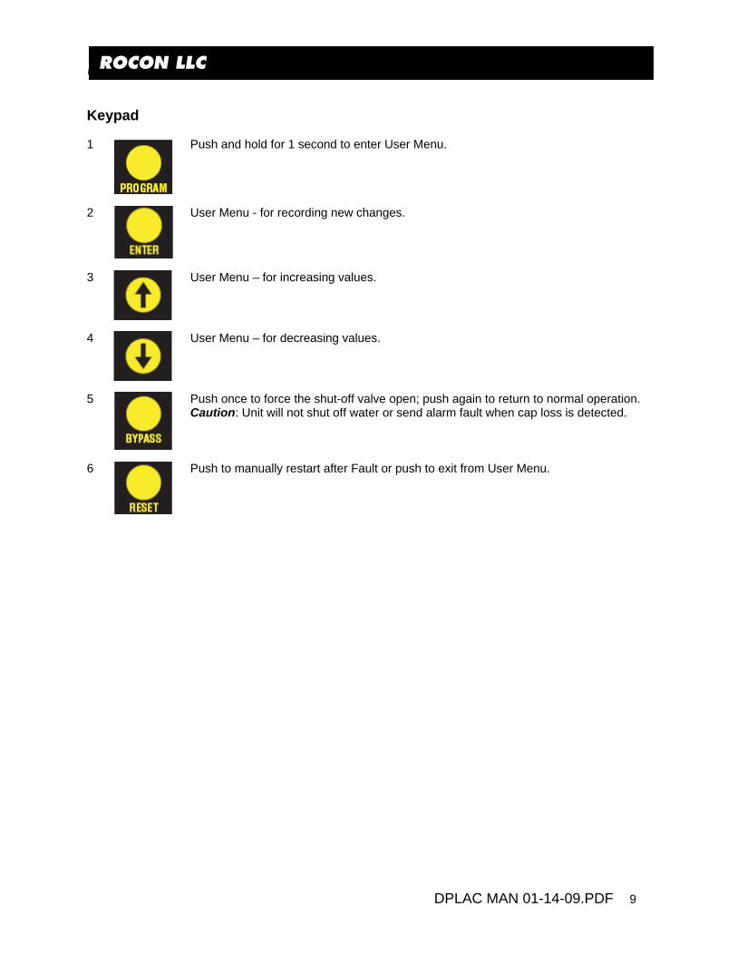
ROCON LLC Keypad 1
Push and hold for 1 second to enter User Menu.
2
User Menu - for recording new changes.
3
User Menu – for increasing values.
4
User Menu – for decreasing values.
5
Push once to force the shut-off valve open; push again to return to normal operation. Caution: Unit will not shut off water or send alarm fault when cap loss is detected.
6
Push to manually restart after Fault or push to exit from User Menu.

ROCON LLC
DPLAC MAN 01-14-09.PDF 10
ROCON LLC INSTALLATION 1 DeltaPoint unit is preferred to be mounted on the outside of the fence line, for ease of service. 2 DeltaPoint can be mounted in any orientation: horizontally, vertically or at any other angle. The
orientation has no effect on performance. It is suggested that unions or hosing be used when connecting to the main supply and return piping, this will facilitate ease of maintenance or removal of unit if needed.
3 The Cover can be rotated 180° to change the location of the shut off devices. Contact factory. 4 Caution: Brass pipe nipples installed on the “Supply” and “From Cell” ports cannot be removed.
They are needed for proper operation of the flow sensors 5 See DIMENSIONS for mounting hole pattern. 6 Connecting fluid ports: The unit has ¾-inch NPT female pipe ports. Port 1 “SUPPLY” cooling water
into the unit, Port 2 “TO CELL” cooling water to tooling or robot, Port 3 “FROM CELL” returns water from the cell or robot. Port 4 “RETURN” cooling water leaving the DeltaPoint unit.
7 Units can be installed where the pipe or hose diameter is larger than the port size. Do not exceed
¾-pipe or hose diameter with the 4 GPM unit and 1-inch pipe or hose diameter with the 12 GPM unit. Caution: Water flow cannot exceed 5 GPM for a 4 GPM unit and 15 GPM for a 12 GPM unit.
8 Connecting electrical power. All units have an Electrical Callout Tag reference page 20 that
describes the pin number, location, wire color and function. 9 Caution: When the water inlet ball valves is opened do it SLOWLY to prevent water hammer
damage to the SENSORS. 10 Installation is complete.
ROCON LLC
DPLAC MAN 01-14-09.PDF 11
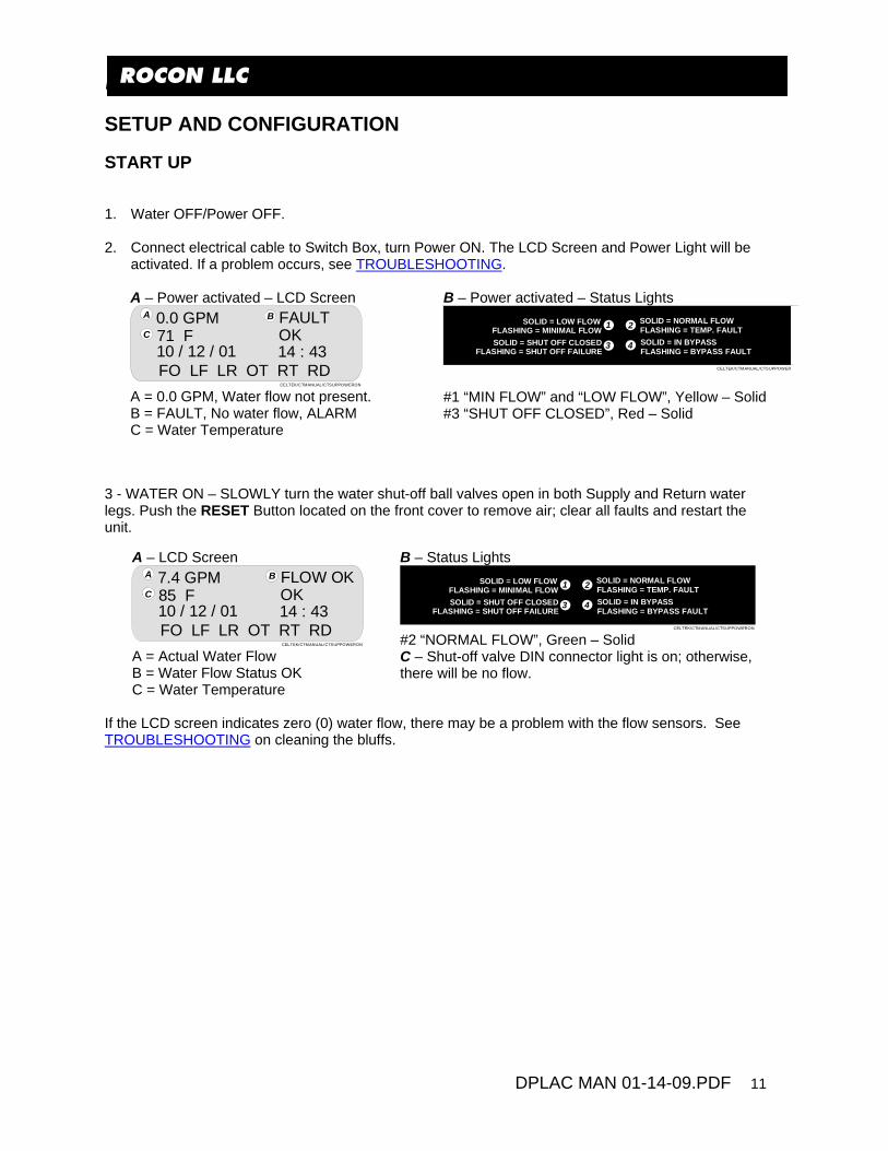
ROCON LLC SETUP AND CONFIGURATION START UP 1. Water OFF/Power OFF. 2. Connect electrical cable to Switch Box, turn Power ON. The LCD Screen and Power Light will be
activated. If a problem occurs, see TROUBLESHOOTING. A – Power activated – LCD Screen
71 F FAULT
10 / 12 / 01
0.0 GPMOK14 : 43
FO LF LR OT RT RDCELTEK/CTMANUAL/CTSUPPOWERON
A B
C
A = 0.0 GPM, Water flow not present. B = FAULT, No water flow, ALARM C = Water Temperature
B – Power activated – Status Lights SOLID = LOW FLOW
FLASHING = MINIMAL FLOWSOLID = SHUT OFF CLOSED
FLASHING = SHUT OFF FAILURE
SOLID = NORMAL FLOW FLASHING = TEMP. FAULTSOLID = IN BYPASSFLASHING = BYPASS FAULT
1 2
3 4
CELTEK/CTMANUAL/CTSUPPOWERO
#1 “MIN FLOW” and “LOW FLOW”, Yellow – Solid #3 “SHUT OFF CLOSED”, Red – Solid
3 - WATER ON – SLOWLY turn the water shut-off ball valves open in both Supply and Return water legs. Push the RESET Button located on the front cover to remove air; clear all faults and restart the unit. A – LCD Screen
85 F FLOW OK
10 / 12 / 01
7.4 GPMOK14 : 43
FO LF LR OT RT RDCELTEK/CTMANUAL/CTSUPPOWERON
A B
C
A = Actual Water Flow B = Water Flow Status OK C = Water Temperature
B – Status Lights SOLID = LOW FLOW
FLASHING = MINIMAL FLOWSOLID = SHUT OFF CLOSED
FLASHING = SHUT OFF FAILURE
SOLID = NORMAL FLOW FLASHING = TEMP. FAULTSOLID = IN BYPASSFLASHING = BYPASS FAULT
1 2
3 4
CELTEK/CTMANUAL/CTSUPPOWERON #2 “NORMAL FLOW”, Green – Solid C – Shut-off valve DIN connector light is on; otherwise, there will be no flow.
If the LCD screen indicates zero (0) water flow, there may be a problem with the flow sensors. See TROUBLESHOOTING on cleaning the bluffs.

ROCON LLC
DPLAC MAN 01-14-09.PDF 12
ROCON LLC START-UP TEST CYCLE Shut-Off Fault Alarm and Weld Controller Fault Alarm Test If unit is operational with water flow present: 1. Turn one of the cooling water ball valves OFF. 2. The LCD screen indicates “Water Flow Fault.” 3. The LED status lights indicate that:
a) Minimum/Low Flow – Solid (Yellow) b) Shut-Off Closed – Solid (Red)
4. The DIN Connector LED is OFF because the shut-off valve solenoid coil is deactivated. 5. Confirm that the Weld Controller received “Water Flow Fault”. 6. Open the cooling water ball valve; push RESTART. Unit should be activated as described above. 7. If no problems occurred, proceed to the next test. If unit did not pass, see TROUBLESHOOTING.
Leak and Response Time Test If unit is operational with water flow present: 1. Pull off one of the weld gun arm electrode caps. 2. The water shuts off and the LCD screen indicates “Fault.” Status Lights #1 and #3 are activated. 3. Reinstall weld gun cap. 4. Send a remote RESTART or push RESTART on the front panel of the unit and wait 3 seconds for
the unit to return to normal operation. 5. Pull off the other weld gun arm cap. And verify Steps 1-4, above. 6. If a faster response time is needed, lower the response time and/or the leak rate (see USER
MENU). CAUTION:
• If the setting gets too low or is too fast, false leak faults could occur. Continue testing until satisfactory results are obtained.
• Long hose runs increase response time. 7. If the unit passed the above tests, it is ready for the production line. FACTORY SETPOINTS Parameter 12 GPM Range Factory Setpoint Flow OK 2.4-12.0 4.0 Min Flow 1.5-2.0 2.0 Low Flow Not adjustable <1.5 Leak Rate 0.5-1.0 1.0 Over Temp. 45 – 210 °F 150 °F Response Time 0.5-9.0 sec 1.0 sec. Restart Delay 0.5-9.0 sec. 3.0 sec. Engineering Units English-Metric English

ROCON LLC
DPLAC MAN 01-14-09.PDF 13
ROCON LLC
LCD Screen
93 F OK
10 / 12 / 01
2.0 GPMOK14 : 43
FO MF LR OT RT RDDESIGNER/CELTEK/CTEK3COVERSTATUSLITE
A B
C D
E F
G
LCD, 4 line x 20 character backlit alphanumeric
A The current amount of water flow through the Supply side. Return side water flow is not displayed but it is always close to Supply side; otherwise, a leak fault would occur. Expressed in GPM or LPM.
B The status of the current water flow: OK, Low Flow, Min Flow or Fault.
When in Fault condition, unit sends alarm to weld controller.
C The current temperature of the water. Expressed in Fahrenheit or Celsius.
D The status of the current water temperature: OK or Fault.
E Current MM/DD/YEAR.
F Current time in 24-hour format.
G Tamper Alert: When any setpoint is changed from the factory setting, the software records the date of change. It also indicates the area changed by blinking.

ROCON LLC
DPLAC MAN 01-14-09.PDF 14
ROCON LLC USER MENU The User Menu structure is as follows: 1. Set Flow OK 2. Set Min Flow 3. Set Leak Rate 4. Set Over Temperature 5. Set Response Time 6. Set Restart Delay 7. Set Engineering Units 8. Set Time and Date End of User Menu
The PROGRAM button is used to enter or skip each individual menu. For example, to change Response Time, push PROGRAM 5 times until Response Time is displayed.
In any of the above menus, if no buttons are pushed for 5 seconds, the User Menu reverts back to Run mode.
If any of the above setpoints are changed in the field from the original factory setting, the corresponding flag (Line 4 of the LCD) will flash in Run mode.
Set Flow OK Push PROGRAM Button
What is Displayed:
4.0 GPM Current setpoint Last Change: mm/dd The date shows when this parameter was last changed. If new
setpoint is entered, new Last Change date will be recorded in the memory and “FO” will flash (on line 4 of the LCD) in Run mode, indicating that the factory setpoint has changed.
Adjustable Range: 12 GPM: 2.4 – 12.0 GPM in 0.2 increments. 3 GPM: 1.5 – 3.0 GPM in 0.1 increments.
To change this value, use the UP and DOWN arrows. When the desired value is selected,
push ENTER to record in memory. SET will be displayed on the LCD.
To skip this menu and go to the next, push PROGRAM.
ROCON LLC
DPLAC MAN 01-14-09.PDF 15
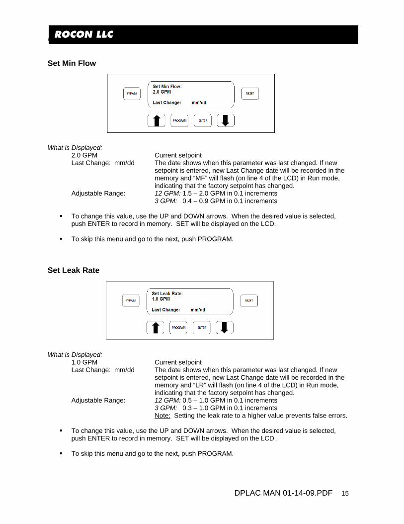
ROCON LLC Set Min Flow What is Displayed:
2.0 GPM Current setpoint Last Change: mm/dd The date shows when this parameter was last changed. If new
setpoint is entered, new Last Change date will be recorded in the memory and “MF” will flash (on line 4 of the LCD) in Run mode, indicating that the factory setpoint has changed.
Adjustable Range: 12 GPM: 1.5 – 2.0 GPM in 0.1 increments 3 GPM: 0.4 – 0.9 GPM in 0.1 increments
To change this value, use the UP and DOWN arrows. When the desired value is selected,
push ENTER to record in memory. SET will be displayed on the LCD.
To skip this menu and go to the next, push PROGRAM. Set Leak Rate
What is Displayed:
1.0 GPM Current setpoint Last Change: mm/dd The date shows when this parameter was last changed. If new
setpoint is entered, new Last Change date will be recorded in the memory and “LR” will flash (on line 4 of the LCD) in Run mode, indicating that the factory setpoint has changed.
Adjustable Range: 12 GPM: 0.5 – 1.0 GPM in 0.1 increments 3 GPM: 0.3 – 1.0 GPM in 0.1 increments Note: Setting the leak rate to a higher value prevents false errors.
To change this value, use the UP and DOWN arrows. When the desired value is selected,
push ENTER to record in memory. SET will be displayed on the LCD.
To skip this menu and go to the next, push PROGRAM.

ROCON LLC
DPLAC MAN 01-14-09.PDF 16
ROCON LLC Set Over Temperature
What is Displayed:
150 °F Current setpoint Last Change: mm/dd The date shows when this parameter was last changed. If new
setpoint is entered, new Last Change date will be recorded in the memory and “OT” will flash (on line 4 of the LCD) in Run mode, indicating that the factory setpoint has changed.
Adjustable Range: 45 – 210 °F in 5 degree increments What Happens:
When water temperature in the return leg exceeds this value, the LCD displays “Fault” but no fault signal is transmitted to the weld controller. The corresponding LED on the membrane also flashes.
To change this value, use the UP and DOWN arrows. When the desired value is selected, push ENTER to record in memory. SET will be displayed on the LCD.
To skip this menu and go to the next, push PROGRAM.
Set Response Time What is Displayed:
1.0 Sec Current setpoint Last Change: mm/dd The date shows when this parameter was last changed. If new
setpoint is entered, new Last Change date will be recorded in the memory and “RT” will flash (on line 4 of the LCD) in Run mode, indicating that the factory setpoint has changed.
Adjustable Range: 0.5 – 9.0 seconds in 0.5 increments What Happens:
DeltaPoint tries to look for a Leak Fault within this timeframe. For higher values, the flow readings are averaged internally for the defined period. This may be a good idea to prevent false errors.
To change this value, use the UP and DOWN arrows. When the desired value is selected, push ENTER to record in memory. SET will be displayed on the LCD.
To skip this menu and go to the next, push PROGRAM.

ROCON LLC
DPLAC MAN 01-14-09.PDF 17
ROCON LLC Restart Delay What is Displayed:
3.0 Sec Current setpoint Last Change: mm/dd The date shows when this parameter was last changed. If new
setpoint is entered, new Last Change date will be recorded in the memory and “RD” will flash (on line 4 of the LCD) in Run mode, indicating that the factory setpoint has changed.
Adjustable Range: 0.5 – 9.0 seconds in 0.5 increments What Happens:
At power up, DeltaPoint waits this long before it starts monitoring the water flow. This is the time that it takes for water flow to stabilize throughout the circuit after the solenoid valve is opened, and for removing all trapped air in the water line after a cap is replaced. Short delays may result in a mismatch between the Supply and Return flow readings, thus issuing an incorrect Fault signal.
To change this value, use the UP and DOWN arrows. When the desired value is selected,
push ENTER to record in memory. SET will be displayed on the LCD.
To skip this menu and go to the next, push PROGRAM.
ROCON LLC
DPLAC MAN 01-14-09.PDF 18
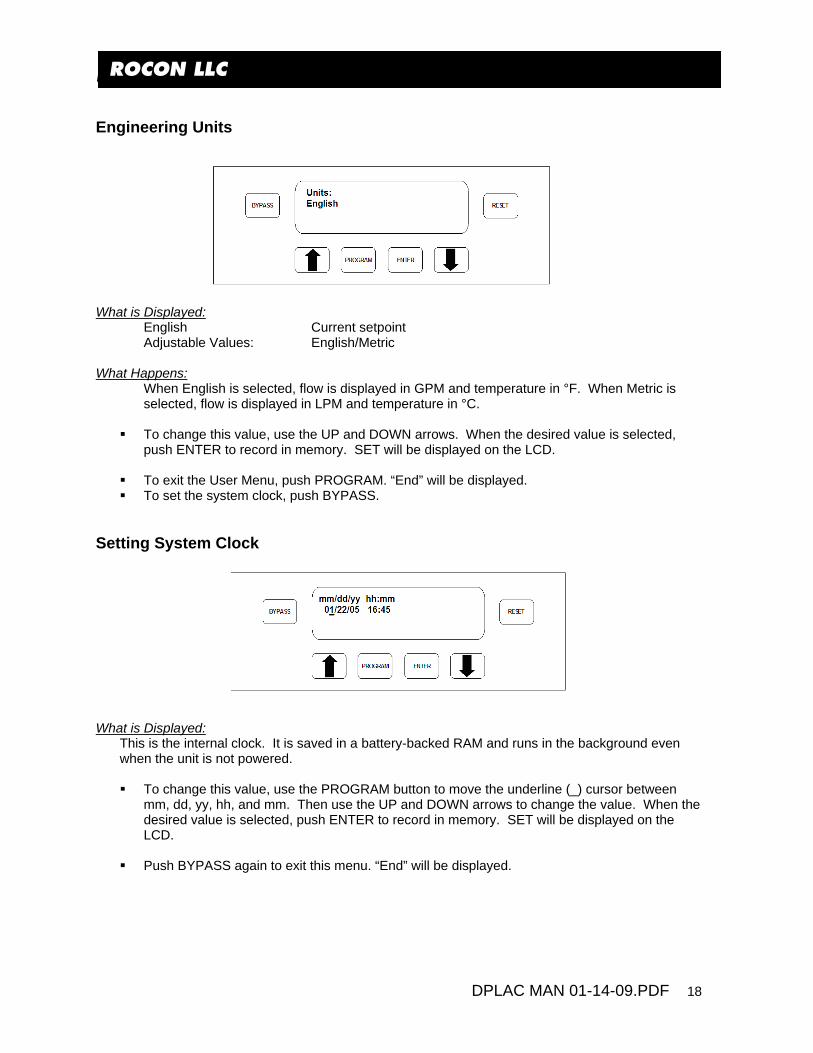
ROCON LLC Engineering Units
What is Displayed:
English Current setpoint Adjustable Values: English/Metric
What Happens:
When English is selected, flow is displayed in GPM and temperature in °F. When Metric is selected, flow is displayed in LPM and temperature in °C.
To change this value, use the UP and DOWN arrows. When the desired value is selected, push ENTER to record in memory. SET will be displayed on the LCD.
To exit the User Menu, push PROGRAM. “End” will be displayed. To set the system clock, push BYPASS.
Setting System Clock
What is Displayed:
This is the internal clock. It is saved in a battery-backed RAM and runs in the background even when the unit is not powered.
To change this value, use the PROGRAM button to move the underline (_) cursor between
mm, dd, yy, hh, and mm. Then use the UP and DOWN arrows to change the value. When the desired value is selected, push ENTER to record in memory. SET will be displayed on the LCD.
Push BYPASS again to exit this menu. “End” will be displayed.
ROCON LLC
DPLAC MAN 01-14-09.PDF 19
ROCON LLC MAINTENANCE DeltaPoint water savers require no maintenance. If the flow tubes become clogged with debris, the unit should be removed for service and cleaning. Significant clogging may result in erratic operation, errors or faults. Do not place tools into the tubes, as this may permanently damage the vortex sensor. The vortex sensor cannot be repaired. To clean the flow tubes, remove the shut-off valve and check valve. Run clean water into the downstream end of each leg. Large objects jammed against the bluff body may be dislodged by lightly tapping the upstream end of the flow tube against a firm surface. CAUTION: Do not tap the flow tube too hard or damage may occur. Shut-Off Valve The manufacturer recommends that the diaphragm be removed and cleaned periodically. The operation of the valve is based on small orifices functioning properly. Depending on the level of water contamination, cleaning frequency could vary from monthly to yearly. If a low-maintenance type valve is required and air is available, please contact factory and request information on the air-operated shut-off valve. Check Valve If check valve is leaking, it may be disassembled and cleaned. Cleaning These meters do not require any special cleaning of the external surfaces. If cleaning is deemed necessary, strong solvents, detergents, or chemicals should not be used. A damp cloth may be used to wipe off dirt or debris. Note If used outside the parameters specified in this manual, the proper operation of the flowmeter cannot be guaranteed.
ROCON LLC
DPLAC MAN 01-14-09.PDF 20
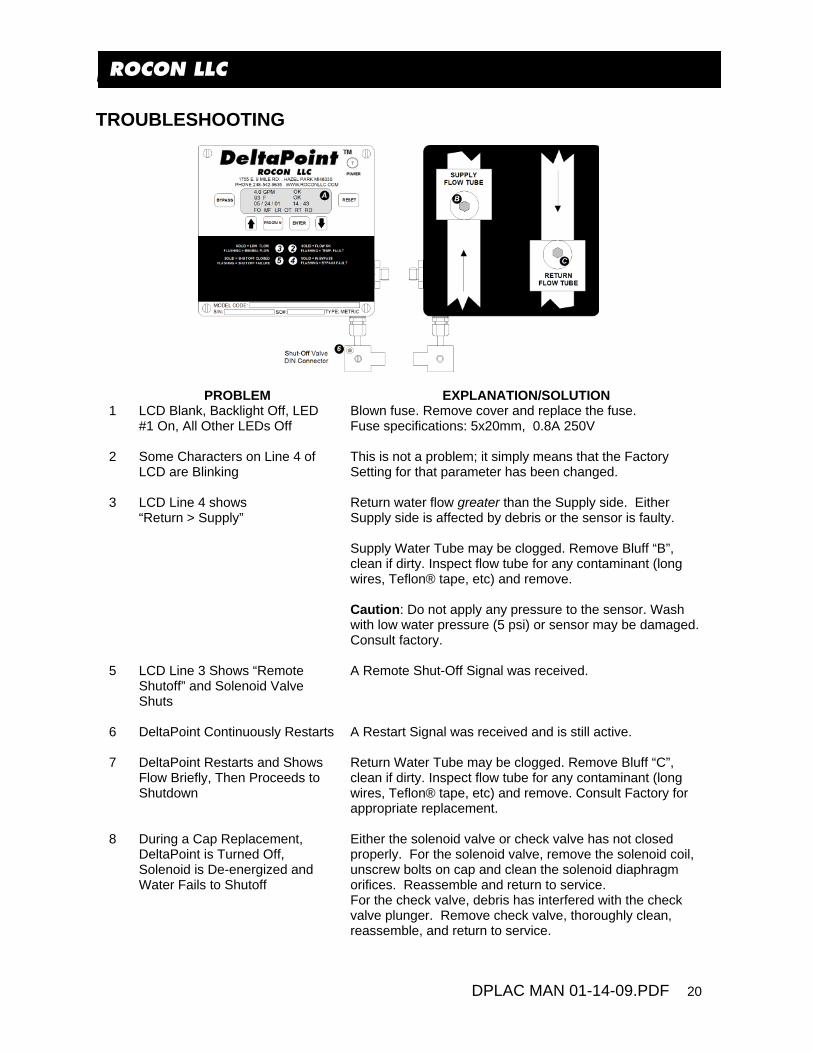
ROCON LLC TROUBLESHOOTING
PROBLEM EXPLANATION/SOLUTION 1 LCD Blank, Backlight Off, LED
#1 On, All Other LEDs Off Blown fuse. Remove cover and replace the fuse. Fuse specifications: 5x20mm, 0.8A 250V
2 Some Characters on Line 4 of
LCD are Blinking This is not a problem; it simply means that the Factory Setting for that parameter has been changed.
3 LCD Line 4 shows
“Return > Supply” Return water flow greater than the Supply side. Either Supply side is affected by debris or the sensor is faulty. Supply Water Tube may be clogged. Remove Bluff “B”, clean if dirty. Inspect flow tube for any contaminant (long wires, Teflon® tape, etc) and remove. Caution: Do not apply any pressure to the sensor. Wash with low water pressure (5 psi) or sensor may be damaged. Consult factory.
5 LCD Line 3 Shows “Remote
Shutoff” and Solenoid Valve Shuts
A Remote Shut-Off Signal was received.
6 DeltaPoint Continuously Restarts A Restart Signal was received and is still active.
7 DeltaPoint Restarts and Shows
Flow Briefly, Then Proceeds to Shutdown
Return Water Tube may be clogged. Remove Bluff “C”, clean if dirty. Inspect flow tube for any contaminant (long wires, Teflon® tape, etc) and remove. Consult Factory for appropriate replacement.
8 During a Cap Replacement, DeltaPoint is Turned Off, Solenoid is De-energized and Water Fails to Shutoff
Either the solenoid valve or check valve has not closed properly. For the solenoid valve, remove the solenoid coil, unscrew bolts on cap and clean the solenoid diaphragm orifices. Reassemble and return to service. For the check valve, debris has interfered with the check valve plunger. Remove check valve, thoroughly clean, reassemble, and return to service.

ROCON LLC
DPLAC MAN 01-14-09.PDF 21
ROCON LLC
PROBLEM EXPLANATION/SOLUTION
9 Flushing the Bluff
Procedure to flush the Bluff Chamber: Step 1 – Closed both Supply/Return ball valves. Bleed off the water pressure by loosening a hose downstream or pulling a weld gun arm cap. Step 2 – Using a 3/32 Allen Head Wrench remove both Bluffs’ hold down screws. Remove bluffs, is there debris on ether bluff – remove. Step 3 – Solenoid Valve – switch to BYPASS position. Step 4 – Tighten the bleed off hose fitting or replace cap. Step 5 – Supply Ball Valve – With the bluffs removed flush the sensor bodies by partially opening the valve and spraying with short bursts for 10 seconds to flush out the bodies. Any contamination build up should have been removed. Step 6 – Reverse above steps and activate the Unit for proper operation.
10 Water doesn’t shutoff. Once both shutoff devices are closed (no electrical power). Step 1 - Partially open the supply ball valve. If the water flows, then there is a problem with the solenoid valve. Step 2 - If the water does NOT flow, shut the supply ball valve off. Step 3 - Partially open the return valve. If the water flows, then there is a problem with the check valve.
11 Solenoid Valve Problem
Solenoid Valve will not shutoff the water: Step 1 - Check the manual override on the valve. Confirm that it is in the NORMAL OPERATION position. Refer to APPENDIX Shutoff Valve Specification. The valve could have debris blocking the balancing orifice or the Plunger Assembly is stuck in the open position in the Sleeve Assembly. Step 2 - Remove the coil / Din connector assembly. Remove the 4 screws holding the cover to the body. Turn cover over and insert a thin wire in the balance hole (farthest from the manual bypass knob) to insure that the orifice is not blocked. Step 3 – Remove the Sleeve Assembly. The internal parts will be the Plunger and Plunger Spring. Do they move up and down freely? If NO then clean or replace with new Sleeve Assembly. Step 4 - Replace the valve cap and the coil, reassemble and confirm that this has resolved the problem by removing another tip.

ROCON LLC
DPLAC MAN 01-14-09.PDF 22
ROCON LLC
PROBLEM EXPLANATION/SOLUTION
12 Check Valve Problem Check Valve will not shut off the water. Step 1 - The only way to remove the debris is to change out the check valve with a replacement and then clean out the check valve on the bench. Step 2 - Remove the snap ring and push the piston out to remove any debris. Step 3 - Replace the new check valve with the cleaned valve, reassemble and confirm that this has resolved the problem by removing another tip.
13 SUPPLY FLOW is greater than RETURN FLOW (UNIT CONTINUOUSLY FAULTS OUT)
This usually is a “return sensor” problem. Refer “COMPARISON TESTING” and “FLUSHING THE BLUFF”.
14 RETURN FLOW is greater than SUPPLY FLOW
This usually is a “supply sensor” problem. Refer “COMPARISON TESTING” and “FLUSHING THE BLUFF”.
15 Replacing the Sensor
Procedure to replace the a sensor: Step 1 - Remove Power / Ethernet Cables. Step 2 - Turn off the water and bleed off the pressure by loosening the hosing downstream (drains water out of sensor chamber, preventing water leaking into electrical box). Step 3 – Remove the Cover – slotted screw driver. Step 4 – Remove the Key Pad circuit board – slotted screw driver. Step 5 – Remove the LCD screen – #2 Phillips screw driver. Step 6 – Remove screws from hold-down bracket of the sensor to be swapped – Phillips screw driver. Step 7 - Using a pair of needle nose pliers, remove the sensor. (Note the position of the “slot” in the sensor is vertical, following the flow). Step 8 – Install new sensor and o ring assembly with needle nose pliers. CAUTION: Sensor SLOT must be aligned “perfectly” with the water flow direction. Slot can be rotated 180 degrees. Step 9 - Replace the hold down bracket and screws, wipe down any water. Step 10 – Replace the LCD screen, Key Pad and Cover. Step 11 – Confirm the bleed off fitting is tight and the Supply/Return water ball valves OPEN. Step 12 – Plug in the Power and Ethernet cables Step 13 - Re-evaluate the unit. Push the “DOWN” Arrow. ADVANCED TRAINING NEEDED FOR FOLLOW: Adjusting the replaced sensor’s flow rate to match the other sensor’s flow rate by turning the sensor pot. The flow rates should be within 0.1 of a gallon of each other. Contact factory for training.

ROCON LLC
DPLAC MAN 01-14-09.PDF 23
ROCON LLC
PROBLEM EXPLANATION/SOLUTION
16 If all else fails
If both sensors are drastically off the expected flow (by more than a gallon) and it appears that there is a major problem. You have 2 options: Option 1 ship the unit to Rocon for recalibration or Option 2 Rocon can furnish electronics “kit,” which will have the motherboard and both sensors. This would be equivalent to replacing the entire unit. To replace the Ethernet motherboard with its accompanying sensors (S or I=Supply and R or O=Return): Step 1 – Shut off the supply/return water ball valves Step 2 - Remove Power and Ethernet cables. Step 3 - Remove the LCD display (4 Phillips head screws) and keypad (2 slot head screws). Step 4 - Unplug all sensors (2 flow and 1 temp). Step 5 - Remove the 2 slot head screws and 1 Phillips head screws holding the mother board to the box. Step 6 – Remove the Keypad standoff. Step 7 – Remove motherboard Step 8 – Remove supply sensor hold down bracket and pull the sensor assembly out. Label with tape SUPPLY. Step 9 – Remove the return sensor as describe in step 8. Step 10 - Replace the sensors from the kit, follow the same procedure as describe in “Replacing the Sensor” Please note Kit – Supply/Return Sensor must be installed in their respective chambers. Step 11 – Install the Kit Motherboard, Keypad and LCD screen as describe above. Step 12 - Reconnect the power cables. The unit should be operating properly. If not, refer to “Flushing the Bluff”. Consult factory if problem.
17 Bypass
There are both electronic and manual bypasses on the units. The electronic bypass is a button on the face of the unit, and once pushed energizes the solenoid valve coil and sends a signal to the robot that the unit is in bypass. The coil will continue to be energized, until the button is pushed again. The manual bypass overrides the solenoid coil completely. It does not give a signal to the robot and water flow is maintained, regardless of the unit’s status.
ROCON LLC
DPLAC MAN 01-14-09.PDF 24
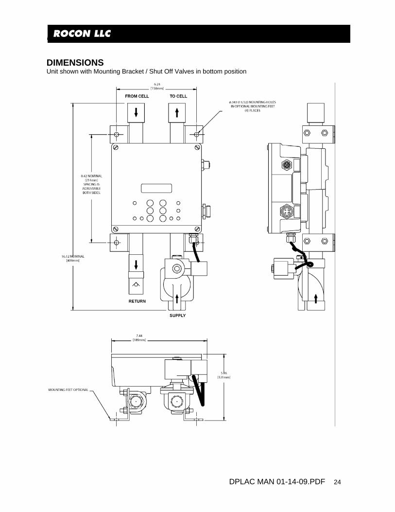
ROCON LLC DIMENSIONS Unit shown with Mounting Bracket / Shut Off Valves in bottom position

ROCON LLC
DPLAC MAN 01-14-09.PDF 25
ROCON LLC Unit shown with Shut Off Valves in top position

ROCON LLC
ROCON LLC MODEL CODES MODEL CODES
DELTA POINT TMTM
DPLAC MAN 01-14-09.PDF 26
HOW TO ORDER Select appropriate symbols and build a model code number, as in example shown:
DP 6F2D1RB 6 -EXAMPLE : *****
GPM SIZE0.5 - 3.0 GPM / (1.9 - 11.4 LPM)........ = A
Special Options If Required
DESIGN NUMBERSubject to change
11116 -----
CONNECTOR TYPEMini ................................................... = 1
3 -
Micro ................................................. = 2
N-
Not Used.................................... = N
1.5 -12.0 GPM / (5.7 - 45.4 LPM)......... = B
PORT SIZE FOR "A" or "B"
*ISO 1179 Adapter Fittings
OPTIONSNo Options Picked ............................. = NShut-Off Valve Air Operated............... = A
DeviceNet Wiring Options
3/4 NPTF........................................= 6 3/4 -14 BSPP*................................= 6G*
Solenoid Interrupt .............................. = H
DPMC 0305
Language Chip (English Standard) Spanish............................................. = S
RECEPTACLE1 -
= 6E6 Pin, Turck, Micro, FS4.6(EOA)........
CONNECTOR MANUFACTURERFactory Standard ...............................= F
2 -
Others Consult Factory
CONNECTOR TYPEMini ................................................... = 1
3 -
Micro ................................................. = 2
4 - VOLTAGE
24 Volt DC NPN (Sourcing) (24V A).. = D1120 Volt AC ......................................... = A
24 Volt DC PNP (Sinking) (0V A).......= D2
Not Used................................... = N
= 66 Pin (DC) Single or Dual (AC)** Key..
Standard Wiring Options
RESTART SIGNAL - DC ONLYStd. 24 VDC = Active HIGH Restart ...... = R5 -
0 VDC = Active LOW Restart ........ = 0
2 Connector (AC/DC) Single Key....... = 6E/32 Connector (AC/DC) Single Key....... = 6E/6
5 Pin (DC) Single or Dual** Key.......... = 54 Pin (DC) Single or Dual** Key......... = 43 Pin (DC) Single or Dual** Key......... = 3
2 Connector (AC/DC) Combo Key......= 5/4D**Dual Key add "D"
Cables - Configuration
4 Pin,Single or Dual** Key x 5M ...... 5 Pin,Single or Dual** Key x 5M ......
= 4 = 5
6 Pin,Single Key x 5M ..................... = 6E6 Pin,Single or Dual** Key x 5M ...... = 6
3 Pin,Single or Dual** Key x 5M ...... = 3
24 Volt DC SSR ................................= D3
Remote Operation - Consult Factory
Remote Shutoff .................................. = R
RECEPTACLE FUNCTION1 - DeviceNet - 5 Pin Male........................= D5
Auxiliary Power - 4 Pin Male............. = A4
CONNECTOR TYPEMini ................................................... = 1
7 -
Micro ................................................. = 2
5 -
10 - DeviceNet w/Pass ThroughConsult Factory- Pass Through
RECEPTACLE FUNCTION
CONNECTOR MANUFACTURERFactory Standard ...............................= F
2 - Others Consult Factory
CONNECTOR MANUFACTURERFactory Standard ............................. = F
6 -
Others Consult Factory
9 - Optional Connector4 Pin, Factory, Micro, Female............ = BEL
GENDERMale ...................................................= M
4 -
Female............................................... = F
GENDERMale ...................................................= M
8 -
Female............................................... = F
Turck - RSFP40................................ = T
ROCON LLC
DPLAC MAN 01-14-09.PDF 26
ROCON LLC
DELTA POINTHOW TO ORDER Select appropriate symbols and build a model code number, as in example shown:
DP 6F2D1RB 6 -EXAMPLE : *****
GPM SIZE0.5 - 3.0 GPM / (1.9 - 11.4 LPM)........ = A
Special Options If Required
DESIGN NUMBERSubject to change
11116 -----
CONNECTOR TYPEMini ................................................... = 1
3 -
Micro ................................................. = 2
N-
Not Used.................................... = N
1.5 -12.0 GPM / (5.7 - 45.4 LPM)......... = B
PORT SIZE FOR "A" or "B"
*ISO 1179 Adapter Fittings
OPTIONSNo Options Picked ............................. = NShut-Off Valve Air Operated............... = A
DeviceNet Wiring Options
3/4 NPTF........................................= 6 3/4 -14 BSPP*................................= 6G*
Solenoid Interrupt .............................. = H
DPMC 0305
Language Chip (English Standard) Spanish............................................. = S
RECEPTACLE1 -
= 6E6 Pin, Turck, Micro, FS4.6(EOA)........
CONNECTOR MANUFACTURERFactory Standard ...............................= F
2 -
Others Consult Factory
CONNECTOR TYPEMini ................................................... = 1
3 -
Micro ................................................. = 2
4 - VOLTAGE
24 Volt DC NPN (Sourcing) (24V A).. = D1120 Volt AC ......................................... = A
24 Volt DC PNP (Sinking) (0V A).......= D2
Not Used................................... = N
= 66 Pin (DC) Single or Dual (AC)** Key..
Standard Wiring Options
RESTART SIGNAL - DC ONLYStd. 24 VDC = Active HIGH Restart ...... = R5 -
0 VDC = Active LOW Restart ........ = 0
2 Connector (AC/DC) Single Key....... = 6E/32 Connector (AC/DC) Single Key....... = 6E/6
5 Pin (DC) Single or Dual** Key.......... = 54 Pin (DC) Single or Dual** Key......... = 43 Pin (DC) Single or Dual** Key......... = 3
2 Connector (AC/DC) Combo Key......= 5/4D**Dual Key add "D"
Cables - Configuration
4 Pin,Single or Dual** Key x 5M ...... 5 Pin,Single or Dual** Key x 5M ......
= 4 = 5
6 Pin,Single Key x 5M ..................... = 6E6 Pin,Single or Dual** Key x 5M ...... = 6
3 Pin,Single or Dual** Key x 5M ...... = 3
24 Volt DC SSR ................................= D3
Remote Operation - Consult Factory
Remote Shutoff .................................. = R
RECEPTACLE FUNCTION1 - DeviceNet - 5 Pin Male........................= D5
Auxiliary Power - 4 Pin Male............. = A4
CONNECTOR TYPEMini ................................................... = 1
7 -
Micro ................................................. = 2
5 -
10 - DeviceNet w/Pass ThroughConsult Factory- Pass Through
RECEPTACLE FUNCTION
CONNECTOR MANUFACTURERFactory Standard ...............................= F
2 - Others Consult Factory
CONNECTOR MANUFACTURERFactory Standard ............................. = F
6 -
Others Consult Factory
9 - Optional Connector4 Pin, Factory, Micro, Female............ = BEL
GENDERMale ...................................................= M
4 -
Female............................................... = F
GENDERMale ...................................................= M
8 -
Female............................................... = F
Turck - RSFP40................................ = T
DeltaPoint TM
ROCON LLC
DPLAC MAN 01-14-09.PDF 27
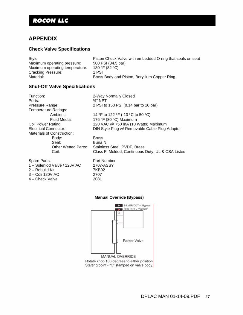
ROCON LLC APPENDIX Check Valve Specifications Style: Piston Check Valve with embedded O-ring that seals on seat Maximum operating pressure: 500 PSI (34.5 bar) Maximum operating temperature: 180 °F (82 °C) Cracking Pressure: 1 PSI Material: Brass Body and Piston, Beryllium Copper Ring Shut-Off Valve Specifications Function: 2-Way Normally Closed Ports: ¾” NPT Pressure Range: 2 PSI to 150 PSI (0.14 bar to 10 bar) Temperature Ratings:
Ambient: 14 °F to 122 °F (-10 °C to 50 °C) Fluid Media: 176 °F (80 °C) Maximum
Coil Power Rating: 120 VAC @ 750 mA (10 Watts) Maximum Electrical Connector: DIN Style Plug w/ Removable Cable Plug Adaptor Materials of Construction:
Body: Brass Seal: Buna N Other Wetted Parts: Stainless Steel, PVDF, Brass Coil: Class F, Molded, Continuous Duty, UL & CSA Listed
Spare Parts: Part Number 1 – Soleniod Valve / 120V AC 2707-ASSY 2 – Rebuild Kit 7KB02 3 – Coli 120V AC 2707 4 – Check Valve 2081
Manual Override (Bypass)

ROCON LLC
DPLAC MAN 01-14-09.PDF 28
ROCON LLC
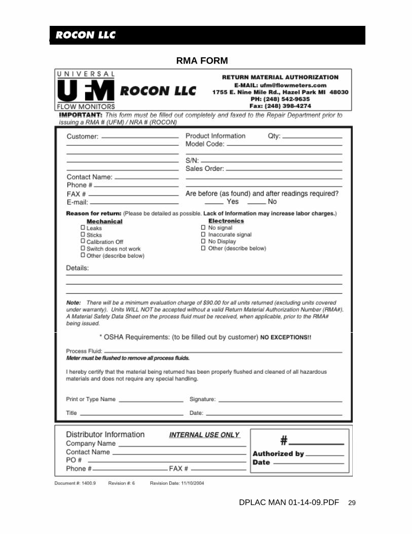
RMA NOTICE RETURN MATERIAL AUTHORIZATION
Please read the following UFM policy information carefully. By following the guidelines outlined below you will assist in providing a timely evaluation and response regarding the status of your flow meter. UFM evaluates all AUTHORIZED RETURNED MATERIALS in a timely manner and will promptly provide notification regarding the status of the related materials and/or a written quotation indicating the total charges and description of the necessary repairs. 1 All returns must have a RMA form completed by the customer. 2 Any meter returned that was previously in service must have the OSHA requirements completed
and a MSDS included where applicable. 3 An RMA number will only be issued when UFM has received a copy of the completed RMA form
and any applicable MSDS. 4 A "Return Goods" shipping label (located in the back of the Instruction Manual) must be used for
returning materials to UFM. 5 Returned goods must be shipped prepaid or they will be rejected. REPAIRABLE MATERIAL Written or verbal authorization to proceed with the repair under an assigned Purchase Order, must be received within 30 days of repair quotation. If the unit(s) are repaired, the $90.00 evaluation charge will be applied to the quoted repair costs. If no repairs are authorized within this 30 day period, the customer will be billed $90.00 plus shipping charges and the materials will be returned to the customer. NON-REPAIRABLE MATERIAL If materials are found not repairable, a written notice that the material is not repairable will be provided to the customer by UFM. If no disposition to scrap or return the material is received from the customer within 30 days, unrepairable material will be scrapped and the customer will be billed the $90.00 evaluation charge. If a UFM replacement unit is purchased within 30 days of non-repairable condition notice, the $90.00 evaluation fee will be waived. The return of non-repairable materials may be ordered by customer Purchase Order providing for shipping and handling charges. RETURN FOR RESTOCK All goods returned for restock adjustment must be: A. New and unused. B. Returned to the factory within ONE YEAR of date of original shipment. C. Returned through the distributor where the goods were originally purchased. This material will also be subject to an evaluation charge of $90.00. The customer will be advised of the restocking adjustment for all restockable goods. Upon acceptance of the restocking adjustment, by the customer, the $90.00 evaluation fee will be waived and a credit issued by UFM. The customer will be advised of any non-restockable goods and will be charged the $90.00 evaluation fee plus any shipping charges if returned to the customer. If no disposition is received by UFM within 30 days, the goods will be scrapped and the $90.00 evaluation fee will be billed. WARRANTY RETURNS Warranty returns must be shipped prepaid to UFM. UFM will review the goods and advise the customer of the evaluation and validity of the warranty claim. Valid warranty claims will be repaired or replaced at no charge. No evaluation fee will be charged for repairs made under warranty. Return shipping costs will be prepaid by UFM. Should UFM determine the returned material is not defective under the provisions of UFM's standard warranty; the customer will be advised of needed repairs and associated costs. All materials returned for warranty repair that are determined to not have a valid warranty claim will be subject to the "Repairable Material" policy outlined above.
ROCON LLC
DPLAC MAN 01-14-09.PDF 29
ROCON LLC
RMA FORM

ROCON LLC
DPLAC MAN 01-14-09.PDF 30
ROCON LLC
ROCON / DELTAPOINT WARRANTY 1) ACCEPTANCE AND INTEGRATION CLAUSE: This Sales Order Acknowledgment and the sales order information that Rocon LLC attaches to or associates with it (this “Acknowledgement”), constitutes an acceptance by Rocon of an offer by the buyer upon the conditions and terms and at the prices stated in this Acknowledgement. This Acknowledgment contains the entire understanding of Rocon and the buyer regarding the subject matter of this Acknowledgement. This Acknowledgement may only be modified by a writing signed by the party against whom enforcement is sought. 2) WAIVER: Waiver by Rocon of any default(s) by the buyer shall not constitute waiver by Rocon of any of the conditions of the agreement between Rocon and the buyer as set forth here under with respect to any further or subsequent default by the buyer. 3) FORCE MAJEURE: Rocon shall not be responsible for failure or delays in deliveries due to fire, strikes, breakdowns, acts of God, failure of carriers, inability to secure required materials, or other causes beyond Rocon's control. Buyer waives any claims for damage arising by virtue of delay in delivery of material by Rocon. 4) LIMITED WARRANTY: (a) Warranty: For a period of one year from the date of manufacture, Rocon warrants that each product covered by this Acknowledgement will be free from defects in material and workmanship. In order to qualify for any remedy provided in this Acknowledgement, buyer must give notice to Rocon within the one-year period, return the product to Rocon freight paid and intact with Material Safety Data Sheets covering all substances passing through the product or that form a residue on the product. (b) Exclusive Remedy. The buyer's EXCLUSIVE REMEDY for failure of any product to conform to any warranty or otherwise for any defect is, at Rocon’s sole option, (i) repair, (ii) replacement, or (iii) refund of the entire purchase price for the specific product. Without limiting the foregoing, in no case will Rocon be liable for deinstallation of any defective product or installation of any repaired or replacement product THIS REMEDY IS THE EXCLUSIVE REMEDY AVAILABLE TO THE BUYER OR ANY OTHER PERSON. ROCON SHALL NOT BE LIABLE FOR ANY DIRECT, INDIRECT, INCIDENTAL, CONSEQUENTIAL, SPECIAL, PUNITIVE, OR OTHER DAMAGES IN CONNECTION WITH ANY CAUSE OF ACTION, WHETHER IN CONTRACT, TORT, OR OTHERWISE. (c) Disclaimer of Other Warranties. The express warranty in this Acknowledgement is in lieu of any other warranty, express or implied. Without limiting the foregoing, ROCON DISCLAIMS THE IMPLIED WARRANTY OF MERCHANTABILITY AND ANY IMPLIED WARRANTY OF FITNESS FOR A PARTICULAR PURPOSE. 5) Products purchased by OEMs (original equipment manufacturers) are warranted only for the specific programs (installations for specific customers) designated when so identified.