Embed Size (px)
Citation preview
1
139587_05 GF 200 DV IPI January 2016
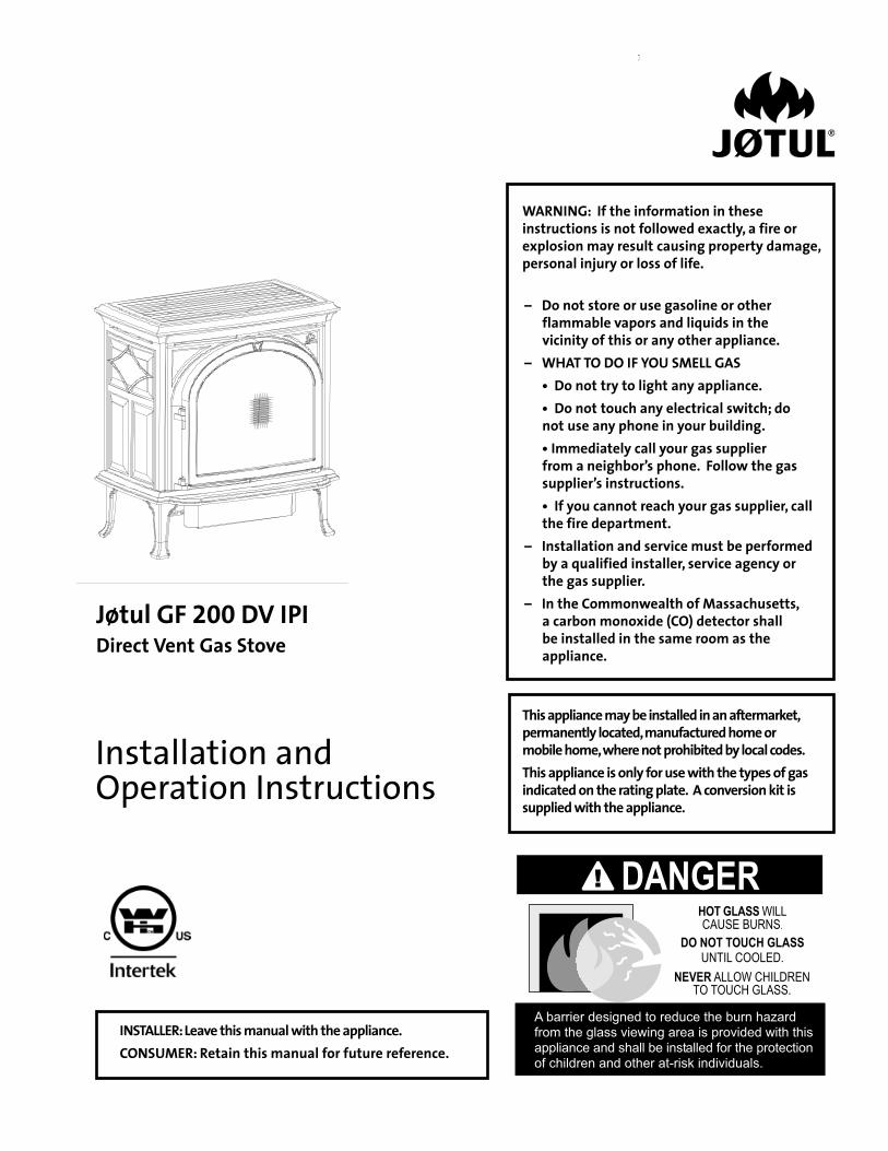
Jøtul GF 200 DV IPI Direct Vent Gas Stove
Installation and Operation Instructions
– Do not store or use gasoline or other flammable vapors and liquids in the vicinity of this or any other appliance.
– WHAT TO DO IF YOU SMELL GAS • Do not try to light any appliance. • Do not touch any electrical switch; do
not use any phone in your building. • Immediately call your gas supplier
from a neighbor’s phone. Follow the gas supplier’s instructions.
• If you cannot reach your gas supplier, call the fire department.
– Installation and service must be performed by a qualified installer, service agency or the gas supplier.
– In the Commonwealth of Massachusetts, a carbon monoxide (CO) detector shall be installed in the same room as the appliance.
WARNING: If the information in these instructions is not followed exactly, a fire or explosion may result causing property damage, personal injury or loss of life.
This appliance may be installed in an aftermarket, permanently located, manufactured home or mobile home, where not prohibited by local codes.This appliance is only for use with the types of gas indicated on the rating plate. A conversion kit is supplied with the appliance.
INSTALLER: Leave this manual with the appliance.CONSUMER: Retain this manual for future reference.
����������������������������������������������� ������������������������������������������������������������������������������������������������������������������������������������
��������������������������
�����������������������������������
�������������������������������
�������

2
139587_05 GF 200 DV IPI January 2016
�We recommend that our gas products be installed and serviced by professionals who are certified in the U.S. by the National Fireplace Institute® (NFI) as NFI Gas Specialists.
Natural Gas / 69.11% Propane / 68.97%
Jøtul GF 200 DV IPI
THIS OWNER’S MANUAL PROVIDES INFORMATION TO ENSURE SAFE INSTALLATION AND EFFICIENT, DEPENDABLE OPERATION OF YOUR FIREPLACE INSERT. PLEASE READ THESE INSTRUCTIONS IN THEIR ENTIRETY AND MAKE THEM AVAILABLE TO ANYONE USING OR SERVICING THIS GAS INSERT.DO NOT ATTEMPT TO ALTER OR MODIFY THE CONSTRUCTION OF THIS APPLIANCE OR ITS COMPONENTS. ANY MODIFICATION OR ALTERATION WILL VOID THE WARRANTY, CERTIFICATION AND LISTING OF THIS APPLIANCE.THIS HEATER MUST BE INSTALLED AND MAINTAINED BY A QUALIFIED SERVICE AGENCY.
Suggested Tools for Installation and Service• External regulator (for Propane only)• Piping which complies with local code• Manual shut-off valve - T-Handle required in Massachusetts• Sediment trap - if required by code• Tee joint• Pipe wrench• Pipe sealant• 10 mm open end wrench• 1/2”, 7/16” open end wrench• Phillips head screwdriver
• Flat head screwdriver• 1/4” nut driver• Gloves• Safety glasses• Torx T-20 screwdriver • Tin snips
Installation Requirements for the Commonwealth of MassachusettsTHIS PRODUCT MUST BE INSTALLED BY A LICENSED MASTER OR JOURNEYMAN PLUMBER OR GAS-FITTER WHEN INSTALLED IN THE COMMONWEALTH OF MASSACHUSETTS.
1. If there is not one already present, on each floor level where there are bedroom(s), a carbon monoxide detector and alarm shall be placed in the living area outside the bedroom(s). The carbon monoxide detector shall comply with NFPA 720 (2005 Edition).
2. A carbon monoxide detector shall: a) Be located in the room that houses the appliance or equipment;
b) Be either hard-wired or battery powered or both; and
c) Shall comply with NFPA 720 (2005 Edition).
3. A Product-approved vent terminal must be used, and if applicable, a Product-approved air intake must be used. Installation shall be in strict compliance with the manufacturer’s instructions. A copy of the installation instructions must remain with the appliance or equipment at the completion of the installation.
PLEASE NOTE:It is normal for smoke and odor to occur during the initial stages of operation, depending upon temperatures generated over time. This “curing” condition can be alleviated by promoting fresh air circulation within the immediate vicinity of the appliance.

3
139587_05 GF 200 DV IPI January 2016
Jøtul GF 200 DV IPI Lillehammer
Manufactured and Distributed by: Jøtul North America
55 Hutcherson Dr. Gorham, Maine 04038
Certified Test StandardsThis appliance complies with National Safety stan-dards and is tested and listed by Intertek Testing Ser-vices of Middleton, Wisconsin to ANSI Z21.88-2014, CSA 2.33-2014, CAN/CGA 2.17-M91, and CSA P.4-01.2
Your stove has a unique serial number stamped on the rating plate which is hung on the back. Please record the serial number in the space below. You may also wish to attach your purchase receipt to this page for future reference.MODEL NAME: Jøtul GF 200 DV IPI Lillehammer
SERIAL NUMBER:_______________________________ DATE OF PURCHASE:____________________________
AUTHORIZED DEALER:__________________________ ADDRESS ___________________________________ PHONE: ____________________________________
INSTALLER: __________________________________ FUEL TYPE: ____________________________________
FUEL CONVERSION: NO _______ YES______ INTALLATION DATE: _____________________________
INSTALLATION TECHNICIAN: ______________________
Table of ContentsService Tools .............................................2 Specifications ............................................4 Unpacking the Stove ..............................4 General Information ................................ 5 Safety Information .................................. 5 Installation Requirements .....................6 Location ................................................6 Hearth Protection ...............................6 Clearances .............................................6 Mantel & Trim ...................................... 7 Alcove .................................................... 7 Venting Requirements ........................8 Vent Restriction ....................................8 Termination Matrix .............................9 Baffle & Deflector Use...................... 10 Vertical Termination ........................... 11 Horizontal Termination .................... 14 Vent Terminal Clearances ................15 Fuel Conversion ....................................... 16 Gas Connection ....................................... 18 Gas Pressure ............................................ 19 High Altitude Adjustment ................... 19 Optional Brick Panel Installation ...... 20 Optional Wall Thermostat ................... 20 Log Set Installation ................................ 21 System Check .........................................22 Flame Picture Adjustment ...................23 Operation .................................................24 Maintenance .......................................... 26 Glass Replacement ............................ 26 Optional Blower .....................................27 Appendix ................................................. 29 Wiring Diagram ................................. 29 Mobile Home Requirements .......... 29 Illustrated Parts Lists ...................30-33 Accessory Listing ............................... 33 Warranty Statement ..............................34 Lighting Instructions ............................. 35
Direct Vent Gas Heater
4
139587_05 GF 200 DV IPI January 2016
���������
��������������
���������������
���������
��������
��������������
��������������
�������������
���������
�������������
����������
�������������
�������������
�������� �������� �������� ���������� ���
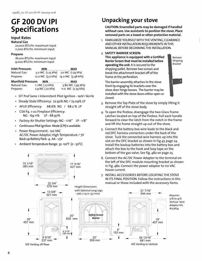
GF 200 DV IPI SpecificationsInput RatesNatural Gas 20,000 BTU/hr. maximum input
11,000 BTU/hr. minimum input
Propane 18,000 BTU/hr. maximum input
9,000 BTU/hr. minimum input
Inlet Pressure: MIN MAX Natural Gas: 5.0 WC (1.25 kPa) 7.0 WC (1.74 kPa)Propane: 12.0 WC (3.0 kPa) 14.0 WC (3.48 kPa)
Manifold Pressure: MIN MAX Natural Gas: 1.1 WC (.27 kPa) 3.80 WC (.95 kPa)Propane: 2.9 WC (.72 kPa) 11.0 WC (2.74 kPa)
• SIT Prof lame 1 Intermitent Pilot Ignition - 120V / 60 Hz • Steady State Efficiency: 72.92% NG / 73.09% LP
• AFUE Efficiency: 68.6% NG / 68.2 % LP• CSA P4. 1-02 Fireplace Efficiency: NG - 69.11% LP - 68.97%• Factory Air Shutter Settings: NG - 1/16” LP - 1/8” • Continuous Pilot Ignition Mode (CPI) is available • Power Requirement: 120 VAC AC/DC Power Adaptor, High Temperature / 7V Back-up Battery Pack: 4, AA - 1.5V• Ambient Temperature Range: 32 -122°F (0 - 50°C)
Unpacking your stove CAUTION: Enamelled parts may be damaged if handled
without care. Use assistants to position the stove. Place removed parts on a towel or other protective material.
1. FAMILIARIZE YOURSELF WITH THE VENTING, CLEARANCE AND OTHER INSTALLATION REQUIREMENTS IN THIS MANUAL BEFORE BEGINNING THE INSTALLATION.
2. SAFETY BARRIER SCREEN: This appliance is equipped with a Certified Barrier Screen that must be installed before operating the unit. It is secured to the shipping pallet. Remove two screws and break the attachment bracket off of the frame at the perforation.
The barrier assembly attaches to the stove front by engaging its brackets over the stove door hinge bosses. The barrier may be installed with the stove doors either open or closed.
3. Remove the Top Plate of the stove by simply lifting it straight off of the stove body.
4. To open the firebox, disengage the two Glass Frame Latches located on top of the firebox. Pull each handle forward to clear the latch from the notch in the frame and lift the frame straight up out of the stove.
5. Connect the battery box wire leads to the black and red DFC harness connectors under the back of the stove. Tuck the connected wire harness up into the slot on the DFC bracket as shown in Fig 47, page 24. Install the backup batteries into the battery box and attach the box to the hook and loop tape on the bottom of the gas valve. See fig. 48a on page 25.
6. Connect the AC/DC Power Adaptor to the terminal on the left of the DFC module mounting bracket as shown in Fig. 48a. Connect the power adaptor to 110 VAC house current.
7. INSTALL ACCESSORIES BEFORE LOCATING THE STOVE IN ITS FINAL POSITION. Follow the instructions in this manual or those included with the accessory items.
Height Dimensions with Optional Long Legs: - add 2 1/4 in. (57 mm)
Safety Screen Barrier
Requires 5/8-to-4/6 Vertical Vent Adaptor Kit, #157674
Remove Shipping Bracket

5
139587_05 GF 200 DV IPI January 2016
Hardware Bag Contents• Fuel Conversion Kit - LP ............................................157669• Rock Wool, 1 oz. ............................................................157259• Wall Shield ...................................................................225426* Air Deflector ............................................................... 225092• AC/DC Power Adaptor ..............................................225492• Battery Box ..................................................................224262
• 1.5v AA Batteries, 4
General InformationTHIS HEATER MUST BE INSTALLED AND MAINTAINED
BY A QUALIFIED SERVICE AGENCY.
The installation and repair of this appliance must be done by a qualified service person. Failure to properly install and maintain this heater could result in an unsafe or hazardous installation, which may result in a fire, explosion, property damage, personal injury or loss of life.
This appliance should be inspected before use and at least annually. More frequent cleaning may be required due to excessive lint from carpeting, bedding material, etc. It is imperative that control compartments, burners, and circulating air passageways of the appliance be kept clean. See Maintenance, page 27, for details.
THIS APPLIANCE MUST NOT BE CONNECTED TO A CHIMNEY OR FLUE SERVING ANY OTHER APPLIANCE.
The installation must conform to local codes. Your local Jøtul dealer can assist you in determining what is required in your area for a safe and legal installation. Some areas require a permit to install a gas burning appliance. Always consult your local building inspector, or authority having jurisdiction, to determine what regulations apply in your area.
CODE COMPLIANCE : Your local officials have final authority in determining if a proposed installation is acceptable. Any requirement that is requested by the local authority having jurisdiction, that is not specifically addressed in this manual, defaults to local code. In the absence of local codes, the installation requirements must comply with the current edition of National codes. In the U.S., these requirements are established in the National Fuel Code, ANSI Z223.1.(NFPA 54) current edition. In Canada, the codes have been established in CAN/CGA B149 Fuel Installation Code, current edition..
DO NOT OPERATE THIS STOVE IF ANY PART HAS BEEN UNDER WATER. Call a qualified service technician to inspect the heater and to replace any part of the con-trol system and any gas control which may have been under water.
Safety InformationDue to the high operating temperatures this appliance
should be located out of traffic and away from furniture and draperies. Maintain proper clearance to combustible mantels and fireplace trim.
Children and adults should be alerted to the hazards of high surface temperatures and should stay away to avoid burns or clothing ignition.
Young children should be supervised while they are in the same room as the appliance. Toddlers, young children and others may be susceptible to accidental contact burns. A physical barrier, such as a child guard, is recommended to be used if there are at-risk individuals in the house. To restrict access to a fireplace or stove, install an adjustable safety gate to keep toddlers, young children and other at-risk individuals out of the room and away from hot surfaces.
A barrier designed to reduce the risk of burns from the hot viewing glass is provided with this appliance and shall be installed for the protection of children and other at-risk individuals.
If the barrier becomes damaged, the barrier shall be replaced with the manufacturer’s barrier for this appliance. See fig. 72, page 34 for part numbers.
Any safety screen, guard, or barrier removed for servicing an appliance must be replaced prior to operating the appliance.
Clothing or other flammable materials should not be placed on or near the fireplace.
Never allow anyone to use the fireplace if they are unfamiliar with its operation.
NEVER store or use gasoline or any other flammable vapors or liquids in the vicinity of this appliance.
Never burn any solid materials (wood, cardboard, paper, coal, etc.) in this appliance. Use with natural gas or propane fuel ONLY.
Do not slam or strike the glass panel.This appliance is NOT for use with aftermarket glass doors.Wear gloves and safety glasses while installing or
performing maintenance procedures on this appliance.

6
139587_05 GF 200 DV IPI January 2016
LocationIn selecting a location for the stove, consider the following points: 1) Heat distribution 2) Vent termination requirements 3) Gas supply line routing 4) Traffic areas, furniture, draperies, etc.
The GF 200 DV IPI may be located on or near conven-tional construction materials, however, proper clearance to combustibles must be maintained in order to provide adequate air circulation around the appliance. Also, it is important to provide adequate access around the stove for servicing and proper operation.
The clearance and hearth specifications listed in this manual are the minimum requirements for combustible material. A combustible material is anything that can burn (i.e. sheet rock, wall paper, wood, fabrics etc.). These surfaces are not limited to those that are visible and also include materials that may be located behind non-com-bustibles.
If you are not sure of the combustible nature of a material, consult your local fire officials. Remember, “Fire Resistant” materials are considered combustible: they are difficult to ignite, but will burn. Also, “fire-rated” sheet rock is considered combustible.
Floor ProtectionThis appliance CANNOT be installed directly on carpeting, vinyl, linoleum or wood laminate flooring, such as Pergo®.
If this appliance will be installed on any combustible material OTHER THAN WOOD, a floor pad must be in-stalled that is either metal, wood, ceramic tile, stone, or a listed hearth pad. This floor protection must extend the full width and depth of the appliance. It is not necessary to remove carpeting, vinyl or linoleum from underneath the floor protection. See fig. 1.
Figure 1. Suggested hearth dimensions shown are slightly larger than the minimum requirement.
24” (609 mm)
18” (457 mm)
Stove and Vent Clearance RequirementsThe clearances specified and diagrammed here are established from the stove body. The safety barrier has no affect on clearances to combustible material.The Wall Shield provided in the hardware package may be used to obscure the Vent Adaptor. The shield has no impact on clearances to combustible material.
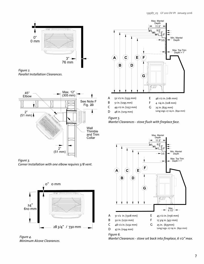
Minimum Clearances from the Stove to Combustibles: Measured from the stove top plate. See figs. 2-6.Rear: 0” (0 mm) Ceiling: 18 1/2” (470 mm)Corner: 2” (50 mm) Sides: 3” (76 mm)
Minimum Clearances between Vent Pipe and Combustible Materials:Horizontal Run: Off the top of the pipe 2” (50 mm) Off the sides and bottom 1” (25 mm)Vertical Run: All sides 1” (25 mm)
Alcove InstallationMaximum Alcove Depth: 24” (610 mm)Minimum Alcove Width: 28 3/4” (730 mm)Minimum Alcove Ceiling Height from floor: 42 1/2” (1080 mm)
Installation Requirements
7
139587_05 GF 200 DV IPI January 2016
Figure 6. Mantel Clearances - stove set back into fireplace, 6 1/2” max.
Figure 5. Mantel Clearances - stove flush with fireplace face.
A 52 1/2 in. (1333 mm)
B 51 in. (1295 mm)
C 49 1/2 in. (1257 mm)
D 48 in. (1219 mm)
�����
��������
����
����������������
����������������
����� ��� �����������
���
� � �
� �
�
�
�����
��������
����
����������������
����������������
����� ��� �����������
���
� � �
� �
�
�
����������
A 51 1/2 in. (1308 mm)
B 50 in. (1270 mm)
C 48 1/2 in. (1232 mm)
D 47 in. (1194 mm)
Figure 4. Minimum Alcove Clearances.
Figure 2. Parallel Installation Clearances.
E 45 1/2 in. (1156 mm)
F 17 3/4 in. (451 mm)
G 25 in. (635mm) Long Legs: 27 1/4 in. (692 mm)
E 46 1/2 in. (1181 mm)
F 4 1/4 in. (108 mm)
G 25 in. (635 mm) Long Legs: 27 1/4 in. (692 mm)
�������������������
���������
���������
������
�������
Figure 3. Corner Installation with one elbow requires 5/8 vent.
�����������������
�������
����������������������
���������
���������
����������������
23

8
139587_05 GF 200 DV IPI January 2016
�������
Vent RestrictionThe GF 200 DV IPI is equipped with an Exhaust Restrictor Plate which enables you to regulate the flow of exhaust gas. The plate prevents overly strong draft that can cause poor combustion and weak flame picture. Follow the guidelines below, and on the following pages, to determine the correct restrictor plate setting for your particular installation configuration.
Exhaust RestrictorThe Exhaust Restrictor is an adjustable shutter located within the firebox exhaust outlet. It is adjusted by moving a pivot pin from the factory-set, fully OPEN (no restriction) to fully CLOSED, (full restriction ). The Minus and Plus signs on the dial relate to degrees of restriction, from less to more. See Fig. 8. The five lettered positions correlate to the termination zones (A,B,C,D,E) diagramed in figure 9. Use the diagram to determine the degree of restriction and shutter setting you should use.
Adjusting Exhaust Restrictor Plate: 1. Use the Vent Termination Matrix to determine which
setting position to use.2. Lift the Top Plate from the stove.3. Locate the restrictor adjustment dial on the top of the
exhaust outlet. Use a 1/4” nut driver to loosen the lock nut and pivot the dial to the position appropriate to your termination zone. See figs. 8 and 9.
4. Tighten the lock nut and replace the Top Plate.
Venting RequirementsThe Jøtul GF 200 DV IPI gas stove may be installed with a vertical or horizontal termination and must conform to the configuration requirements described below.
This appliance is approved for use with vent systems from the following manufacturers: • M&G DuraVent, Inc. (Direct Vent Pro Series) • American Metal Products (Amerivent) • Security Chimneys International, Ltd. (Secure Vent) • Selkirk Metalbestos (Direct Temp) • Metal-Fab, Inc. (Direct Vent) • Industrial Chimney Corp. (ExcelDirect) • Bernard Dalsin Mfg. (Pro Form)
Use parts of one manufacturer only - DO NOT MIX VENT COMPONENTS FROM DIFFERENT MANUFACTURERS IN THE SAME SYSTEM.
Installation of any components not manufactured or approved by Jøtul or failure to meet all clearance requirements will void all warranties and could result in property damage, bodily injury, or serious fire.
The approved vent configurations described in this manual are derived from extensive testing under controlled laboratory conditions. Gas appliance performance can be negatively affected by variables present in the installation environment, i.e: atmospheric pressure, strong prevailing winds, adjacent structures and trees, snow accumulation, etc. These conditions should be taken into consideration by the installer and stove owner when planning the vent system design.
IMPORTANT• JOINT SEALING REQUIREMENT:
APPLY A 1/8” BEAD OF HIGH-TEMPERATURE SEALANT OR MIL-PAC® TO THE MALE SECTION OF THE INNER VENT PIPE. THE CEMENT SHOULD FORM A SEAL BETWEEN THE INNER AND OUTER PIPES.
• NEVER MODIFY ANY VENTING COMPONENT, OR USE ANY DAMAGED VENTING PRODUCT.
• THE GAS APPLIANCE AND VENT SYSTEM MUST BE VENTED DIRECTLY TO THE OUTSIDE OF THE BUILDING AND NEVER ATTACHED TO A CHIMNEY SERVING A SOLID FUEL OR GAS BURNING APPLIANCE. EACH DIRECT VENT GAS APPLIANCE MUST HAVE ITS OWN SEPARATE VENT SYSTEM. COMMON VENT SYSTEMS ARE PROHIBITED.
• IF VENTING SYSTEM IS DISASSEMBLED FOR ANY REASON, REINSTALL PER THE INSTRUCTIONS PROVIDED FOR THE INITIAL INSTALLATION.
Figure 7.
Approved Horizontal and Vertical Vent Terminations• Up to four 45° or two 90° elbows are permitted
in addition to the starter elbow. A horizontal run, however, must be reduced by 5 feet for each additional elbow, whether 45° or 90°.
• NOTE: Long vent runs (over 12 ft.) in uninsulated air space may require operation in CPI mode for best performance.
• ALL VENTING MUST TERMINATE (END) WITHIN ONE OF THE DESIGNATED AREAS.
• SET STOVE EXHAUST RESTRICTOR TO THE POSITION THAT CORRESPONDS TO THE VENT TERMINATION AREA IN THE MATRIX. When termination is exactly on a division line, use the less restrictive position. For example, if termination is at 11 ft./3ft., restriction should be set at Position D.
The circled letter designations in the vent matrix in figure 9 correspond to the Exhaust Restrictor dial settings on the stove. First, determine which vent termination zone is appropriate for your installation, then adjust the restrictor to the corresponding position as shown in figure 9.

9
139587_05 GF 200 DV IPI January 2016
Figure 8. Use 1/4” socket driver to loosen the Exhaust Restrictor dial and adjust as appropriate for your termination zone.
Figure 9. Vent Termination Zone Matrix - NG / LP
��������������
���������� ���
����������
���
���
����
��
����
�
� ������ ����
�
�
�������������
�
��
�
�
�
�
�
�
�������������
���
���
����
��
���
������
�����
���
���
� �
����
�
��
��
NOTE: 4/6 VENT MAXIMUM RUN DIRECTLY OFF REAR TO HORIZONTAL TERMINATION IS 6 INCHES.
10
139587_05 GF 200 DV IPI January 2016
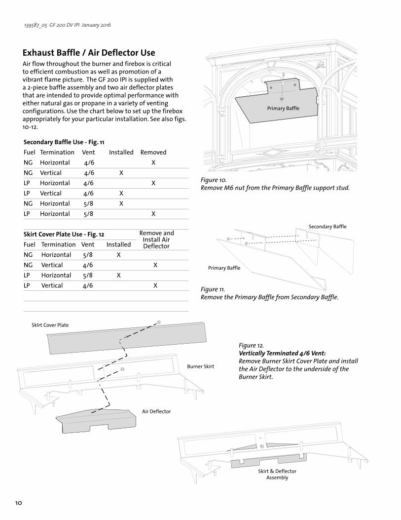
Figure 10. Remove M6 nut from the Primary Baffle support stud.
Exhaust Baffle / Air Deflector Use Air flow throughout the burner and firebox is critical to efficient combustion as well as promotion of a vibrant flame picture. The GF 200 IPI is supplied with a 2-piece baffle assembly and two air deflector plates that are intended to provide optimal performance with either natural gas or propane in a variety of venting configurations. Use the chart below to set up the firebox appropriately for your particular installation. See also figs. 10-12.
Figure 11. Remove the Primary Baffle from Secondary Baffle.
Secondary Baffle
Primary Baffle
Secondary Baffle Use - Fig. 11Fuel Termination Vent Installed RemovedNG Horizontal 4/6 XNG Vertical 4/6 XLP Horizontal 4/6 XLP Vertical 4/6 XNG Horizontal 5/8 XLP Horizontal 5/8 X
Skirt Cover Plate Use - Fig. 12Fuel Termination Vent Installed NG Horizontal 5/8 XNG Vertical 4/6 XLP Horizontal 5/8 XLP Vertical 4/6 X
Remove and Install Air Deflector
Figure 12. Vertically Terminated 4/6 Vent: Remove Burner Skirt Cover Plate and install the Air Deflector to the underside of the Burner Skirt.
Sklrt Cover Plate
Burner Skirt
Air Deflector
Skirt & Deflector Assembly
Primary Baffle

11
139587_05 GF 200 DV IPI January 2016
Vertical Vent TerminationThe Jøtul GF 200 DV IPI can be vertically vented through a ceiling or to a roof termination with the following guidelines:
Vertically terminated vent runs require 4/6 vent pipe. Use Vertical Vent Adaptor Kit 157674. See figs. 13 and 14.
Remove the Burner Skirt Cover Plate and install the Air Deflector plate to the underside of the Burner Skirt as shown in fig. 12.
The termination should fall within the shaded areas of the grids depicted in the Vent Matrix, fig. 9, page 9.
Total run must not exceed 20 ft. (6.09 m).
Vent Terminus Clearance: In no case shall any discharge opening on the cap be less than 18 in. (457 mm) horizontally from the roof surface. See fig. 15.
Steep roofs, nearby trees, and predominantly windy conditions can contribute to poor draft and/or promote draft reversal. Increasing the height of the vent may alleviate these conditions.
Use Wall Straps to support an offset pipe run at intervals of three feet to avoid excessive stress on the offsets.
Elbows: Four 45°, or two 90° elbows may be used. Do not include the 45° elbow attached to the stove. Whenever possible use 45° elbows instead of 90° elbows as they are less restrictive to exhaust gas and intake air flow.
A firestop is required at every floor. The floor opening should be framed to 10" X 10" inside dimension.
Any venting that is exposed in living space above the first floor must be enclosed. Always maintain the required 1" clearance from all sides of the vertical vent system. Insulation in attic space must be retained by an insulation barrier.
�������������������
���
�������
���
������������
�������
����������������������
�������
�������
Figure 13. Remove rear shroud to access the Adaptor Collar.
Figure 15. Vertical vent termination height above roof.
Figure 14. Remove the 5/8 Adaptor Collar components and replace with the 4/6 collar parts.
Use magnetic retrieval tool to keep
screws for reuse.

12
139587_05 GF 200 DV IPI January 2016
Co-linear Vent InstallationThe GF 200 DV IPI may be vented through a masonry or Class A prefabricated chimney using a Co-linear Flexible Vent system approved for use with a solid-fuel burning fireplace. When installed in the manner described below, this system can improve the performance of the appliance in cold climate situations, as well as simplify the vent installation. See fig. 16.
Consult with the local code authority having jurisdiction before proceeding with this type of installation.Refer to the vent manufacturer’s instructions for specific
installation requirements. These installation requirements must be followed:
Vertically terminated vent runs require 4/6 vent pipe. Use 4/6 Vent Adaptor Kit 157674. See figs. 13-14. Use the guidelines for vertical termination on page 11.
The chimney flue must be thoroughly cleaned and inspected by a qualified chimney service person.
In a masonry chimney, a fireclay liner must be present the entire length of the chimney.
Prefabricated chimneys must be UL 103 or ULC S-629 listed and have a minimum INSIDE diameter of 6 inches, (150 mm).
No appliance can be installed into a chimney flue serving any other appliance of any kind.
THE AIR INTAKE FLEX PIPE MUST EXTEND 6 FEET BEYOND THE DAMPER AREA OF THE FIREPLACE.
If the intake flex duct does not extend the full length of the chimney and connect to both the unit and the termination cap, A METAL BLOCK OFF PLATE MUST BE CONSTRUCTED AND INSTALLED ABOVE THE UNIT PRIOR TO THE END OF THE INTAKE FLEX AND MUST COMPLETELY SEAL THE CHIMNEY FLUE FROM THE ROOM.
If there is enough vent length and room in the flue, adding a return loop in the air intake run will help prevent draft reversals that can cause cold start problems.
Figure 16. Co-linear Adaptor installed through a masonry chimney. Simpson Dura-Vent components shown.
Figure 17. Simpson Dura-Vent #923GCL Co-linear Adaptor.
Max. offset 24”
(609 mm)
The Air Intake Flex pipe must
extend beyond the
damper.The chimney must be sealed
off from the room by a steel
plate at the damper area.
#991 High Wind Cap
Exhaust GasIntake
AirMax. Co-linear Height - 35 ft.
(10.66 m)
Min. Co-linear Height - 10 ft.
(3.04 m)
Dual 3” Flex Liners
NOTE: THIS VENT CONFIGURATION MAY REQUIRE THE APPLIANCE BE OPERATED IN CPI MODE TO ASSURE ADEQUATE DRAFT AND PROPER PERFORMANCE.
WARNING: FAILURE TO POSITION THE PARTS AND STOVE IN ACCORDANCE WITH THESE DIAGRAMS OR FAILURE TO USE ONLY PARTS SPECIFICALLY APPROVED FOR USE WITH THIS APPLIANCE MAY RESULT IN PROPERTY DAMAGE OR PERSONAL INJURY. BE SURE TO MAINTAIN THE CLEARANCES TO COMBUSTIBLES SPECIFIED IN THIS MANUAL AND IN THE INSTRUCTIONS PROVIDED WITH EACH VENT COMPONENT.
��
���������
�������������

13
139587_05 GF 200 DV IPI January 2016
Figure 18. Vent System through a masonry chimney using the Simpson Dura-Vent Chimney Conversion Kits. Drawing is for illustrative purposes only - DO NOT VENT TWO APPLIANCES INTO A SINGLE CHIMNEY.
Vertical Termination Cap
Cap Adaptor
Support/Wall Thimble Cover
Exhaust Gas
Intake Air
Use Standard Simpson
Dura-Vent ProSeries Pipe from stove to
thimble
4” Flex Pipe not included
in kit
The GF 200 DV IPI is approved for use with components of Simpson DuraVent Chimney Kit 46DVA-KMC and 46DVA-KCT in a masonry chimney or a Kits 46DVA-KCA, 46DVA-KCB, and 46DVA-KCC for prefabricated solid fuel listed chimneys.These installation requirements must be followed:
Vertically terminated vent runs require 4/6 vent pipe. Use 4/6 Vent Adaptor Kit 157674. See figs. 13-14.
Use the guidelines for vertical termination shown on page 11.
In masonry chimney, a fireclay liner or listed steel liner, must be present the entire length of the chimney.
Chimney height should not exceed 20 ft. (6.09 m).
The liner must have an inside dimension of 6” round or greater.
Prefabricated chimneys must be UL 103 or ULC S-629 listed and have a minimum INSIDE diameter of 6 inch-es, (150 mm). Prefabricated chimneys must be listed for the specific Simpson Dura-Vent Chimney Conversion Kits noted above.
Masonry or Prefabricated Chimney Conversion
IMPORTANT NOTICEIN THE U.S.,THE USE OF AN EXISTING CHIMNEY AS AN AIR INTAKE IS NOT COVERED UNDER THE ANSI Z21.88-1999-CSA 2.33-M99 TEST METHODS AND RESULTING ITS/WHI PRODUCT CERTIFICATION. THE CODE AUTHORITY HAVING JURISDICTION MUST BE CONSULTED PRIOR TO PROCEEDING WITH THIS INSTALLATION METHOD.THIS INSTALLATION IS NOT APPROVED IN CANADA.

14
139587_05 GF 200 DV IPI January 2016
���������
Horizontal TerminationExhaust Restriction: Under normal circumstances, no
exhaust restriction is recommended. Set the restriction shutter to Position A - fully open, fig. 8, pg. 9.
Any horizontal termination must fall within the shaded portion of the vent window matrix shown in fig. 9.
Use of 4" x 6 5/8" vent horizontally terminated, requires that the Secondary Exhaust Baffle be removed. See figs. 21 - 22.
Horizontal termination requirements: 1) If no vertical run, the minimum horizontal run is 6 in. 2) If no vertical run, the maximum horizontal run is 48 in. 3) Maximum vertical run is 20 ft. 4) With any vertical run, the maximum horizontal run is 15 ft.
Up to four 45° or two 90° elbows may be used in addition to the starter elbow. The horizontal run must be reduced by 5 feet for each additional elbow, whether 45° or 90°.
The horizontal termination cap must maintain a 3" clearance to any overhead combustible projections 2 1/2" or less. It must also maintain 12" clearance from projections exceeding 2 1/2". See fig. 24.
Wall Cut-out Opening: A minimum 10" X 10" (250 mm x 250 mm) square hole is required for proper pipe clearances through a combustible wall.
DO NOT FILL AIR SPACE WITH ANY TYPE OF INSULATION.
Any horizontal run of vent must be level or have a 1/4 in. rise for every foot of run toward the termination cap. NEVER ALLOW THE VENTING TO RUN DOWNWARD FROM STOVE TO TERMINATION; DOWNWARD VENT RUNS TRAP HEAT AND CAUSE HIGH TEMPERATURES TO DEVELOP WITHIN THE VENT THAT COULD START A FIRE.
Install a Vinyl Siding Standoff (Simpson Dura-Vent #950) between the vent termination and an exterior wall covered by vinyl siding material to prevent potential heat damage to the siding.
Direct vent terminals may not be recessed into a wall or siding.
Figure 19. 4/6 Vent - Minimum / Maximum run for horizontal termination.
Figure 21. Use 1/2” (10 mm) socket to remove nut from Primary Baffle stud.
Figure 22. Use 1/4” (6 mm) socket driver to remove Primary Baffle from Secondary Baffle.
Secondary Baffle
Primary Baffle
Primary Baffle
Figure 20. 5/8 Vent - Minimum / Maximum horizontal vent - no vertical run. 1/4 inch (6mm) rise per foot is required.
��������
Min: 6” / (152 mm)Max: 48” (122 mm)

15
139587_05 GF 200 DV IPI January 2016
�������
���������
�����������
Figure 23. Vent Terminal Clearances, Canada and United States
Horizontal Termination Clearance
Figure 24. Termination Clearance to overhangs.
�
������������� ���������� ������������ �������������������� �
Canadian Installations 1 U.S. Installations 2
A Clearance above grade, veranda, porch, deck, or balcony 12 in. (30 cm) 12 in. (30 cm)
B Clearance to window or door that may be opened 12 in. (30 cm) 9 in. (23 cm) We recommend 12 in. to prevent
condensation on a window.
C Clearance to permanently closed window 12 in. (30 cm) 9 in. (23 cm) We recommend 12 in. to prevent condensation on a window.
D
Vertical clearance to ventilated soffit located above the terminal within a horizontal distance of 2 ft (60 cm) from the center line of the terminal
18 in, (46 cm) 18 in, (46 cm)
E Clearance to unventilated soffit 12 in,. (46 cm) 12 in,. (46 cm)
F Clearance to outside corner 12 in,. (46 cm) 9 in. (23 cm) We strongly recommend 12 in. particularly where strong winds prevail.
G Clearance to inside corner 12 in,. (46 cm) 9 in. (23 cm) We strongly recommend 12 in. particularly where strong winds prevail.
H Clearance to each side of center line extended above a gas meter or regulator
3 ft. (91 cm) within a height 15 ft. above the meter/regulator assembly *
I Clearance to service regulator vent outlet 3 ft. (91 cm) *
JClearance to nonmechanical air supply inlet to building or the combustion air inlet to any other appliance
12 in. (30 cm) 9 in. (23 cm)
K Clearance to a mechanical air supply inlet 6 ft. (1.83 m) 3 ft. (91) cm above if within 10 ft. (3 m) horizontally
L Clearance above paved sidewalk or paved driveway located on public property 7 ft. (2.13 m) 3 *
M Clearance under veranda, porch, deck, or balcony 12 in. (30 cm) 4 12 in. (30 cm) 4
N Clearance to propane tank relief valve and filler connection 5 ft. (1.52 m) 5 / 10 ft. (3.05 m) 6 5 ft. (1.52 m) 5 / 10 ft. (3.05 m) 6
1) In accordance with the current CSA B149.1, Natural Gas and Propane Installation Code.
2) In accordance with ANSI Z223.1/MNPA 54, National Fuel Gas Code
* For clearances not specified in ANSI Z223.1/NFPA or CSA B149.1, the clearance will be in accordance with local installation codes and the requirements of the gas supplier.
3) A vent shall not terminate directly above a sidewalk or driveway which is located between two single family dwellings and serves both dwellings.
4) Permitted only if veranda, porch, deck, or balcony is fully open on a minimum of two sides beneath the floor.
5) Minimum clearance to tanks not filled on site.
6) Minimum clearance to tanks filled on site from bulk truck.

16
139587_05 GF 200 DV IPI January 2016
Tools required:• 1/2” open ended wrench or deep-well socket, • Torx T20 wrench• 1/4” socket driver or spade screwdriver• 7/16” open-end wrench.
Conversion Kit Contents:• 1, regulator tower labeled for either LP or NG• 2, regulator tower screws• 1, burner orifice (1.20mm - LP / 2.10mm - NG)• Label A - to be completed and applied to
the back of the stove• Label B - apply to the stove’s Rating Plate• Small valve label - apply to valve body
Fuel ConversionThe GF 200 DV IPI gas stove is shipped from the factory equipped to burn NATURAL GAS only. If PROPANE gas is to be used as fuel, the appliance must first be converted for using Propane Conversion Kit 157669 included with the stove. Use Natural Gas Conversion Kit 157670 to change back for use with natural gas.
WARNING:THE CONVERSION KIT IS TO BE INSTALLED BY AN AUTHORIZED JØTUL SERVICE TECHNICIAN IN ACCORDANCE WITH THE MANUFACTURER’S INSTRUCTION AND ALL CODES AND REQUIREMENTS OF THE AUTHORITY HAVING JURISDICTION. FAILURE TO FOLLOW THESE INSTRUCTIONS COULD RESULT IN SERIOUS INJURY OR PROPERTY DAMAGE. THE QUALIFIED AGENCY PERFORMING THIS WORK ASSUMES RESPONSIBILITY FOR THIS CONVERSION.
IN CANADA:THE CONVERSION SHALL BE CARRIED OUT IN ACCORDANCE WITH THE REQUIREMENTS OF THE PROVINCIAL AUTHORITIES HAVING JURISDICTION AND IN ACCORDANCE WITH THE REQUIREMENTS OF THE CAN1-B149.1 AND .2 INSTALLATION CODE.
Figure 26. Loosen the wing nut and push the shutter stem fully to the rear to disengage the burner.
Figure 25. Tilt the burner skirt forward from the rear, then twist end first out through the door opening.
Figure 27. Use a 1/4” socket driver to remove two sheet metal screws to lift burner out of the firebox.

17
139587_05 GF 200 DV IPI January 2016
Fuel Conversion Procedure 1. Turn off gas supply to stove.2. Remove the stove Top Plate.3. Disengage the two Glass Frame Latches and lift the
glass panel frame up and out of the stove. 4. If installed, remove the Embers and Log Set using care
not to damage the fragile log parts.5. Lift out the Burner Skirt. See fig. 25. 6. Reach under the stove and loosen the Air Shutter
wingnut. Pull the shutter stem back to ease burner removal.See fig. 26
7. Lift out the Burner Plate with removal of two screws from the firebox floor. See fig. 27.
8. CHANGE THE INTEGRATED DUAL-FUEL PILOT ORIFICE: a) Loosen two sheet metal screws to pivot the Pilot
Shield out of the way as shown in fig. 28. b) Use the 7/16” wrench to just loosen the pilot head
enough to push in the adjustment slide. See fig. 29. LP : push tab to left (red LP indicator is exposed). NG: push tab to right
9. Change the Burner Injector. See fig. 30. Using a 1/2” open end wrench or deep-well socket remove the burner orifice from its brass elbow housing and replace with the appropriate orifice supplied in the kit.
10. Replace the Burner Plate. Engage the burner tube with the Air Shutter assembly. Be sure the burner is level and secure it to the four support brackets with the screws previously removed.
11. Replace the Valve Regulator. Using a Torx T-20 screwdriver, remove the screws from the front of the regulator. Remove the regulator components and replace with the one from the conversion kit. See fig. 31.
12. Install the identification labels to the stove so that they can be seen by any person who may be servicing the stove. Label A: apply to back of stove Label B: apply to the rating plate attached to the back of the stove. Small Conversion Label: apply to valve.
13. Reassemble the stove, apply gas to the system and check for leaks using a soapy water solution or digital gas detector.
NEVER USE AN OPEN FLAME TO CHECK FOR GAS LEAKS.
Figure 28. Use a 1/4” socket driver to loosen two screws and pivot the Pilot Shield out of the way.
��
Figure 30. Replace the Burner injector.
Figure 29. Integrated dual-fuel pilot orifice- LP position shown.
Pilot Shield
Figure 31. Regulator tower replacement.
Diaphragm
Regulator Tower
Valve Body

18
139587_05 GF 200 DV IPI January 2016
����
Gas Supply ConnectionNOTE: If appropriate, install the optional forced air blower before connecting the gas line, to prevent clearance interference between the two.
The gas supply line connection is made to the left side of the valve. The gas supply line should be 3/8” npt with a 1/2” diameter supply, or the appropriate size to provide sufficient gas pressure to the valve regardless of the input setting.
The use of Flexible Gas Appliance Connectors is acceptable in many areas in the U.S. However, Canadian methods vary depending on local code.
ALL INSTALLATIONS MUST COMPLY WITH LOCAL CODE OR IN THE ABSENCE OF LOCAL CODE, MUST COMPLY WITH THE MOST RECENT EDITION OF THE NATIONAL FUEL GAS CODE ANSI Z223.1/NFPA 54 OR CAN-B149.
All codes require a gas shut-off valve (gas cock) and union, to be installed in the supply line, and in the same room as the appliance. This allows for the disconnection of the stove for servicing and maintenance. See fig. 33.
A T-HANDLE GAS COCK IS REQUIRED IN MASSACHUSETTS TO COMPLY WITH CODE 248CMR.
Secure all joints tightly using appropriate tools and sealing compounds. For propane units be sure to use com-pounds that are propane resistant. Turn on gas supply and test for gas leaks using a soapy water solution. Never use an open flame to check for leaks.
Leak test:1. Mix a 50-50 solution of water and dish
soap.2. Light appliance- see lighting instructions
on the inside back cover of this manual or on the stove’s rating plate.
3. Brush or spray all joints and connections with the soapy water solution.
4. If bubbles appear at any connection or seam or a gas odor is detected, imme-diately turn gas control knob to the OFF position.
5. Tighten or reconnect the leaking joint and retest for any gas leaks.
Figure 33. Supply valve connection fittings.
���������������������� �������
���������������
���������������������������
����������
��������
������������������
���������� ������
������� ���������
�������� �
Fuel Conversion, cont’d.15. Correct gas pressure is essential for efficient and safe
operation of this appliance. Use a manometer to check pressures as specified in the Gas Pressure section of this manual (page 19).
16. Adjust the Air Shutter. You will need to position the shutter to provide a gas/air mixture that will achieve the best flame picture with your particular installation.
Pushing the stem back will restrict air, while pushing it forward will open the shutter and increase air. With some experimentation, you will find the shutter posi-tion that works best for your installation. Start at the following positions for the appropriate fuel: Propane - 1/8” (4mm) Natural gas - 1/16” (2mm)
ALWAYS REFER TO THE LIGHTING INSTRUCTIONS ON THE INSIDE BACK COVER OF THIS MANUAL WHEN LIGHTING YOUR STOVE.
Figure 32. Pull the shutter forward to increase primary air. Push back to restrict air.

19
139587_05 GF 200 DV IPI January 2016
Gas PressureCorrect gas pressure is essential for efficient and safe operation of the GF 200 DV IPI gas stove. It is important that the correct pressure is established at the time of the installation. Proper gas pressure provides a consistent flow of gas to the appliance and is instrumental in checking for gas leaks.
Pressure Test: Attach a manometer to the appropriate test point on the valve. See fig. 34. The gauge connections are located on the front of the valve. Connections are identified by:
A - for Manifold Pressure (the amount of gas that is coming out of the valve to the burner.)
B - for Inlet or Supply Pressure (the amount of gas coming to the valve.)
ALWAYS TEST PRESSURES WITH VALVE CONTROL KNOB SET ON HIGH.
INLET GAS PRESSURES (inches water column)
MIN MAX NATURAL GAS 5.0 7.0 PROPANE 12.0 14.9
The appliance and its appliance main gas valve must be disconnected from the gas supply piping system during any pressure testing on that system at test pressures in excess of 1/2 psig (3.5 kPa).
The appliance must be isolated from the gas supply line by closing its individual manual gas shut-off valve (gas cock) during any pressure testing of the gas supply piping system that is equal to or less than 1/2 psig (3.5 kPa).
MANIFOLD PRESSURES(inches water column)
MIN MAX
NATURAL GAS 1.1 3.8 PROPANE 2.9 11.0
High Altitude AdjustmentThe decreased atmospheric pressure of higher altitudes affects heat value of gaseous fuels. Most gas suppliers derate the gas intended for use at elevations above 2000 feet. Check with your gas supplier before performing derate adjustment to the burner. If the gas supplier does not derate fuels, install High Altitude Adjustment Kit 157675 for Propane and Kit 157676 for Natural gas.
U.S & Canada per ANSI Z21.88-2014• CSA 2.33-2014, CAN/CGA 2.17At 610-1370 meters (2000-4500 ft.), the orifice size is #46 for Natural Gas and #56 for Propane. See data plate for additional information. At higher altitudes, consult the local gas distributor or the authority having jurisdiction for proper rating methods. If the installer must convert the unit to adjust for varying altitudes, the information label must be filled out and applied to the appliance at the time of the conversion.
INSTALLER: Fill out the appropriate information and apply the high altitude conversion label provided to the rating plate on the appliance. See fig. 35.
Derating Procedure• Follow the steps for Burner Injector replacement
in the Fuel Conversion procedure on pages 17-18. Use the injector supplied with the adjustment kit. Detailed instructions are also included in the kit.
• Conduct gas leak and gas pressure tests as de-tailed the preceding section.
• Conduct system check and flame picture adjust-ments as specified on pages 22-23.
Figure 35. High Altitude Conversion Label.
This appliance has been converted for use at an altitude of___________ .Orifice Size: __________ Manifold Press. _______Input Btu/Hr. _________ Fuel Type ___________Date: ___/___/___ Converted by:_____________Cet appreeil a été converti au _____ Injecteur_____ Pression à la tubulure d’alimentation ___________Déoit calorifique ___________
Figure 34. Pressure test points.B
A

20
139587_05 GF 200 DV IPI January 2016
Optional Brick Panel Kit 157666 1. Lift the Top Plate from the stove.2. Disengage the two compression latches from the glass
frame at the top of the firebox and pull the glass frame up and out of the stove.
3. Locate the retainer tabs in the upper corner of each side of the firebox. Bend each retainer tab out enough to engage the side brick panels. See fig. 36.
4. Install the Lower Panel. Position it up against the back wall, resting on the burner skirt.
5. Set the Upper Panel on the Lower Panel. Hold the rear panels in place while setting the Left Side Panel under its retainer tab and against the wall. Bend the retainer down to fully engage the side panel.
6. Engage the Right Side Panel under its retainer tab and seat it against the wall. Bend that retainer tab down to secure the panel in place.
Retainer Tab
Figure 36. Install the Brick Panels.
Optional Wall Thermostat 750003Use only a 750 millivolt DC two-wire circuit wall thermostat with this appliance. The thermostat should be placed in the same room as the heater, typically 5 feet off the floor. Avoid drafty areas or any area that may affect the accuracy of the thermostat.
The thermostat should be connected to the terminal block using a minimum of 16 gauge wire with a maximum length of 25 feet of wire.
Connect the two thermostat wire leads to the terminals on the block located to the left of the valve. Do not overtighten the connections. IT IS NOT NECESSARY TO DISCONNECT ANY OTHER WIRES. See Figs. 37 and 48.
For thermostatic operation, set the On/Off/Stat switch to the Stat position. Set the pilot mode to either IPI or CPI.
At the thermostat, the two wires should be connected to the two connection screws on the thermostat base plate per the manufacturer’s instructions.
CAUTION:LABEL ALL WIRES PRIOR TO DISCONNECTION WHEN SERVICING THE CONTROLS. WIRING ERRORS CAN CAUSE IMPROPER OR DANGEROUS OPERATION. ALWAYS VERIFY PROPER OPERATION AFTER SERVICING THE APPLIANCE.
Figure 37. Accessory wiring diagram.
������������������
������������
��
���
����
��������
������������
���������������
������������������
������������
��
���
����
������������
��������

21
139587_05 GF 200 DV IPI January 2016
Log Set InstallationBrick Kit Note: Install the optional Brick Panel Kit 157666 before installing the log set. See page 20 or the instructions provided with that kit.The GF 200 DV IPI log set must be installed before operating the burner. The log set includes four log pieces, packaged inside the firebox. A quantity of ember stones is included with the log set. Place the logs inside the firebox as illustrated in figs. 38-42. WEAR GLOVES AND HANDLE THE LOG PARTS CAREFULLY.
#157668 Log Set Identification #1 Left Rear 225447
#2 Right Rear 225448 #3 Burner Log 225450 #4 “Y” Log 225449 #5 Ember Stones 225451
The ember stones realistically simulate glowing coals when the burner is operating. These should be spread sparsely over the burner plate and around the logs. Use a pencil to position the stones so as not to block the burner plate porting.
TO INSURE PROPER BURNER FUNCTION, DO NOT OBSTRUCT THE PILOT ASSEMBLY, BURNER SKIRT OPENINGS, OR BURNER PLATE PORTING WITH EMBER STONES. KEEP EMBERS AWAY FROM THE PILOT CARRY-OVER PORTS.
You do not need to use all of the ember stones. With some experimentation, you will find the arrangement and quantity of embers that works best. Depending upon the characteristics of your installation, it is possible that too many ember stones can promote sooting on the logs. Adjust the quantity of ember stones as appropriate to maintain the best overall flame picture and burner performance.
IMPORTANT
Figure 38. Engage the Left Logs with the two pins on the back shelf.
Figure 39. Engage the Right Logs on the other two pins on the back shelf.
Figure 40. Engage the Front Log with the two center pins.
1
2
3

22
139587_05 GF 200 DV IPI January 2016
4
Figure 43. Proper pilot flame appearance relative to burner carry-over porting.
Figure 41. Position the Middle Cross Log as shown.
Figure 42. Place Ember Stones loosely over the burner plate. DO NOT OBSTRUCT THE GAS PORTING. SEE FIG. 43. Use the supplied rock wool sparingly.
Keep ember stones clear of carry-over ports
5
System Check1. PURGING THE GAS LINE: When lighting the appliance
for the first time, it will take a few moments to clear the gas line of air. Once this purge is complete, the appliance will operate as described in the lighting instructions. From a cold start, it may be helpful to let the pilot light burn in CPI mode for 10 - 15 minutes to establish positive draft, before turning the burner on. See the procedure on the inside back cover of this manual. Subsequent burner starts will not require purging the gas line unless the supply line is shut off.
2. PILOT FLAME: You can monitor the pilot flame located under the Rear Log. See fig. 43. The pilot flame should be steady - not lifting or floating. The flame should be blue in color around the pilot hood, with traces of yellow toward the outer edges.
The pilot flame should engulf the top 1/8” of the flame sensor. The pilot flame should project front pilot hood port toward the burner plate carry-over ports. Adjust the pilot flame using the adjustment screw to the left of the valve regulator.
3. MANUAL BURNER ADJUSTMENT: This stove is equipped with a variable gas control valve that allows manual adjustment of the flame height and heat output. To adjust the flame intensity, rotate the regulator knob. Flame height will adjust approximately 50% between the LOW and HIGH settings. See fig. 46, page 23.
NO SMOKE OR SOOT SHOULD BE PRESENT. CHECK LOG PLACEMENT IF ANY SOOT OR SMOKE IS PRESENT. IF SOOT OR SMOKE PERSISTS, THE AIR SHUTTER MAY NEED TO BE ADJUSTED.
See Flame Appearance / Air Shutter for air shutter settings and adjustments. Note: The more offsets there are in the vent system, the greater the need for an air shutter adjustment.
WARNING: AIR SHUTTER ADJUSTMENTS SHOULD ONLY BE PERFORMED BY A QUALIFIED, PROFESSIONAL SERVICE TECHNICIAN.
Figure 44. Manual flame regulation.
RegulatorPilot Adjustment

23
139587_05 GF 200 DV IPI January 2016
Flame Appearance / Air Shutter AdjustmentThe Air Shutter may be adjusted to provide the best flame picture for your specific installation. The factory setting for Natural gas is 1/16” (1.5mm) open. For Propane, the initial recommended setting is 1/8” (3mm) open.
Too large an air opening - the appliance will generate a flame that is blue and transparent, or an “anemic” flame.
Too small an air setting - the appliance will generate very long yellow flames resulting in soot. Sooting produces black deposits on the logs, on the inside walls of the appliance, and potentially on the exterior termination cap. Sooting is caused by incomplete combustion in the flames and lack of combustion air entering the air shutter opening.
To adjust the air shutter: 1. Reach under the stove and loosen the wingnut. See
fig. 45. Slide the wing nut stud forward to open the air shutter and back to provide less air. Make adjustments in 1/16” (1.5mm) increments.
2. Allow the stove to burn for 30 minutes on the HIGH setting, observing the flame continuously. If the flame appears weak, slow, or sooty, repeat the process described above until the flame is as desired.
3. Tighten the wingnut to secure the shutter at the desired setting.
WARNING: AIR SHUTTER ADJUSTMENTS SHOULD ONLY BE PERFORMED BY A QUALIFIED PROFESSIONAL SERVICE TECHNICIAN.
����
Figure 45. Loosen the wing nut to adjust the air shutter. Min. Opening NG: 1/16” (1.5 mm) Factory Setting Min. Opening LP: 1/8” (3 mm)
Figure 46. Normal flame picture.

24
139587_05 GF 200 DV IPI January 2016
OperationImportant Notes
Check the build date on the shipping crate label. If it has been more than 6 months since the build date, be prepared to replace the DFC batteries.
1. For the first several hours of operation, it is common to detect some odor as the metal and manufacturing materials cure under heat. This condition is temporary and can be alleviated by allowing plenty of fresh air to circulate through the area.
2. Condensation may develop on the glass upon each lighting of the appliance. This “fog” will disappear as the glass heats.
3. IMPORTANT: It will be necessary to clean the glass after the first few fires. A white powdery residue will be evident which results from the burner media curing. Use a non-abrasive household glass cleaner and warm water. IF THE GLASS IS NOT CLEANED, THIS RESIDUE CAN CAUSE THE GLASS TO BECOME PERMANENTLY ETCHED. DO NOT USE AMMONIA-BASED CLEANERS.
4. Keep the control compartments and area under the appliance free of dust. Always keep the appliance area clear and free from combustible materials, gasoline and other flammable liquids.
5. This appliance can be operated with a continuously burning pilot flame. Exercise caution when using household products containing combustible vapors.
6. CAUTION: DO NOT OPERATE THIS APPLIANCE WITH THE GLASS PANEL REMOVED, CRACKED OR BROKEN. REPLACEMENT OF THE GLASS SHOULD BE DONE BY A LICENSED OR QUALIFIED SERVICE PERSON. USE ONLY REPLACEMENT GLASS PROVIDED BY YOUR AUTHORIZED JØTUL DEALER. NEVER SUBSTITUTE ANY OTHER TYPE OF GLASS. REMOVE GLASS ONLY FOR ROUTINE SERVICE. ALWAYS HANDLE GLASS CAREFULLY.
WARNING: READ AND UNDERSTAND ALL OPERATING INSTRUCTIONS BEFORE ATTEMPTING TO OPERATE THIS APPLIANCE. DO NOT ALLOW ANYONE TO OPERATE THIS APPLIANCE WHO HAS NOT READ AND UNDERSTOOD THESE INSTRUCTIONS.
WARNING: SEVERE INJURY. THIS APPLIANCE CAN BE SET TO OPERATE THERMOSTATICALLY. BE AWARE THAT THE FIREPLACE MAY BE VERY HOT EVEN WHEN THE BURNER IS NOT APPARENTLY OPERATING. KEEP CHILDREN AWAY FROM THE APPLIANCE.
WARNING:OBSERVE CAUTION NEAR THE GLASS PANEL. THE GLASS MAY SHATTER IF STRUCK BY AN OBJECT. ALWAYS HANDLE THE GLASS PANEL WITH CARE.
DFC Battery Replacement1. Switch Burner to OFF and disconnect power to the stove.2. Access the battery box from under the gas valve. See
fig. 47 and 48a. Disengage the wire harness from the retainer slot on the back of the DFC bracket. Disengage the battery box from the hook & loop tape.
3. Slide the cover plate back to open the box. Install four, 1.5v AA batteries and reattach the box to the underside of the valve. Re-engage the wires with the retainer slot.
4. Reconnect power to the stove.
Figure 47. Battery box to DFC wire harness connection. Tuck harness up into the slot on the back of the DFC module.
Wire Retainer
Slot
Battery Box Harness
DFC Harness
DFC Module Bracket

25
139587_05 GF 200 DV IPI January 2016
OperationFamiliarize yourself with the controls of the GF 200 DV IPI and be sure that anyone else using the appliance is also familiar with the controls and operation procedures. Always follow the Lighting Instructions on the inside back cover of this manual and also located on the inside of the Controls Access Door.
This appliance is equipped with an ignition device that lights the pilot automatically. Do not try to light the pilot by hand.
Locate the Burner Control switches at the top left side of the rear shroud. See fig. 48.1. Set the Burner switch to OFF. Open the main gas
supply line to the stove.2. Connect the AC/DC Power Adaptor to the terminal
on the back of the DFC board bracket. See fig. 48a. Connect the adaptor plug to 110 VAC house current.
3. If a wall thermostat is used, set it to the lowest temperature.
4. Set the Pilot Mode: • CPI for continuous pilot operation • IPI for intermittent operation.
5. Set the Burner Switch to ON. The pilot will light. ON / OFF - use for manual control of the burner. STAT - use with an optional wall thermostat.
6. Flame intensity can be adjusted manually by turning the Valve Regulator knob shown in Fig. 48a.
Figure 48. Burner controls location, viewed from above stove.
���������������������������
����������������������������
��� ����������
����������
����������������
����������������
��������������������
���������������������
���������������������������������������� ���������
Figure 48a. Valve and Blower Controls.
���
���
��
����
���
������
���
��

26
139587_05 GF 200 DV IPI January 2016
Glass CareClean the glass only when necessary. Wipe the surface with a clean, dampened, soft cloth. Follow with a dry, soft towel. Take care not to scratch the glass surface.WARNING: DO NOT USE ABRASIVE CLEANERS ON THE GLASS. NEVER CLEAN THE GLASS WHEN IT IS HOT. DO NOT USE AMMONIA-BASED CLEANING SOLUTIONS .
Gasket InspectionIt is important that the glass gasket be inspected at least annually. Examine the ribbon gasket for signs of dete-rioration and make sure the gasket has a positive seal. Replace the gasket if necessary. Refer to the replacement parts list on page 33. Figure 50. Wrap the gasket around the glass panel.
MaintenanceYour Jøtul GF 200 DV IPI components and its venting system should be inspected before use and at least annually by a qualified service technician.IMPORTANT: ALWAYS TURN OFF THE GAS SUPPLY AND DISCONNECT POWER FROM THE APPLIANCE BEFORE ANY SERVICE WORK IS PERFORMED.
Annual Cleaning Vent SystemThe entire vent system, including the chimney, should be inspected and cleaned every year. If the intake and exhaust venting is disassembled for any reason, it should be reassembled and sealed according to the manufacturer’s instructions provided at the initial installation.
Burner SystemPeriodically inspect the firebox, valve compartment, convection airways and optional blower to BE CERTAIN THAT THE FLOW OF COMBUSTION AND VENTILATION AIR IS UNOBSTRUCTED.
The firebox and valve compartment should be vacuumed annually to remove any dust and debris. Use a soft brush attachment and handle the logs carefully as they are fragile. Vacuum more frequently if there are pets in the home.
The pilot assembly should be inspected and cleaned annually by a qualified technician. Any component showing corrosion should be replaced.
Glass Panel or Gasket Removal1. Lift the Top Plate off of the stove. Release the two Glass
Frame Latches. Pull each latch handle forward forward to disengage the latch from the notches in the glass frame.
2. Lift the glass frame all the way up and out of the top of the stove. Lay this assembly on a flat surface, protecting the frame from scratches using a blanket or towel.
3. The glass panel is held in place by four tabs on the frame. Use a screwdriver or small pliers to pry these up enough to release the glass panel. See fig. 49.
4. Remove the old gasket material.
Glass Panel or Gasket Replacement1. Wrap the new gasketing material evenly around the
edge of the glass, peeling back the protective strip to expose the adhesive as you go. See fig. 50. Press the adhesive side down onto the glass surface. Do not stretch the gasket.
2. Place the gasketed glass within the frame and carefully bend each of the retainer tabs back to secure the glass in the frame. The replacement glass kit 155599 includes 4 compression clips for use in case a tab should break.
Figure 49. Bend the retainer tabs back enough to release the glass panel.
NOTE: INSPECT THE GLASS SURFACE FOR SCRATCHES AS THESE CAN WEAKEN THE PANEL TENSILE STRENGTH.REPLACE THE PANEL IF ANY SCRATCHES ARE FOUND. USE ONLY JOTUL PN 220576. DO NOT USE ANY OTHER TYPE OF GLASS.

27
139587_05 GF 200 DV IPI January 2016
Optional Variable Speed Blower 155631
CONNECT THE GAS SUPPLY TO THE STOVE BEFORE INSTALLING THIS
BLOWER. USE A 90° ELBOW OFF THE GAS VALVE TO CREATE ADEQUATE
GAS LINE CLEARANCE.
THIS BLOWER MUST BE ELECTRICALLY GROUNDED IN ACCORDANCE WITH LO-CAL CODES OR, IN THE ABSENCE OF LOCAL CODES, WITH THE CURRENT ANSI/NFPA 70, NATIONAL ELECTRICAL CODE OR CSA C22.1-CANADIAN ELECTRICAL CODE.
THIS UNIT IS SUPPLIED WITH A THREE-PRONG (GROUNDING) PLUG FOR PRO-TECTION AGAINST SHOCK HAZARD AND SHOULD BE PLUGGED DIRECTLY INTO A PROPERLY GROUNDED THREE-PRONG RECEPTACLE. DO NOT CUT OR REMOVE THE GROUNDING PRONG FROM THE PLUG.
ALWAYS DISCONNECT THE POWER SUPPLY WHEN PERFORMING ANY SERVICE ON THE FIREPLACE INSERT.
Contents 1. Blower 2. Snapstat Wire Harness 3. Control Box 4. Snapstat Bracket 5. Rheostat Knob 6. Snapstat 7. M6 Flange Nuts, (2) 8. M6 x 12 Hex Bolts, (2) 9. #8 x 1/2” Sheet metal screw, (4)
Tools Required • 1/4” socket driver • 10 mm socket driver or wrench
Figure 51. Blower Kit Components
Blower Installation1. Unpack and check the contents of the blower kit. There
is a steel bracket that is not used with the GF 200 stove. Contact your dealer if any damage is evident or parts are missing. See fig. 51.
2. Attach the Control Box to the lower pair of holes on the Snapstat Bracket with two #8 x 1/2” sheet metal screws as shown in figs. 51 and 52.
3. Attach the Control Box assembly to the studs located underneath the stove in the middle of the firebox floor using two M6 hex nuts and a 10 mm socket driver or wrench. See fig. 52.
4. Use two M6 hex nuts to attach the Blower to the mounting holes at the rear of the stove bottom plate.
5. Connect the power cord to 110 AC house current.
1
2
6
8
75 3
4Use Lower Holes for
GF200 DV II
9
7

28
139587_05 GF 200 DV IPI January 2016
Figure 52. 155631 Blower Kit Components used for GF 200 DV IPI Lillehammer.
����������
��
������
�����������
�
��������
��
��
������
�������������������
��
��
��
��
��
Blower OperationThe variable-speed blower will enhance heat circulation around the firebox and out into the room. The blower is controlled by a heat activated switch (snapstat) that will function only when the control switch is in the AUTO setting. After the fire has been burning for a time, the snapstat will react to the heat and activate the blower. Fan speed may be manually adjusted with the rheostat knob. If the burner turns off, the blower will be shut off automatically as the stove cools down.
If automatic blower circulation is not desired, place the blower control switch in the MANUAL position. That will override the snapstat, allowing the blower to run continuously.
CAUTION:LABEL ALL WIRES PRIOR TO DISCONNECTION WHEN SERVICING CONTROLS. WIRING ERRORS CAN CAUSE IM-PROPER AND DANGEROUS OPERATION.VERIFY OPERATION AFTER SERVICING.
ATTENTION:AU MOMENT DE L’ENTRENTIEN DES COMMANDES, ETIQUIETEZ TOUS LE FILS AVANT LE DEBRANCHEMENT. ES ERREURS DE CEBLAGE PEUVENT ENTRA TUN FONC-TIONNEMENT INADEQUAT ET DANGEREUX.
Figure 53. GF 200 DV IPI Blower Wiring Diagram.

29
139587_05 GF 200 DV IPI January 2016
Figure 53. GF 200 DV IPI Blower Wiring Diagram.
Battery Pack Four, 1.5v AA
CPI / IPI Switch SPDT
Burner Switch SPST
DC Power Supply
Figure 54. GF 200 DV IPI Proflame 1 Components
Proflame 1 DFC Wiring Diagram
Appendix
Mobile Home InstallationThe GF 200 DV IPI can be installed for use in a mobile home in the U.S. and Canada provided:1. The stove is secured to the floor of the mobile home.
Use Jøtul Floor Bracket Kit #750304.2. Provision must be made to secure an electrical ground
between the stove and the mobile home chassis.3. The stove is installed in accordance with Title 24 CFR,
Part 3280- Manufactured Home Construction and Safety Standard, in the U.S. In Canada, comply with CSA Z240.4, Gas Equipped Recreational Vehicles and Mobile Housing.
4. Always contact your local officials about installation restrictions and requirements in your area.
THIS APPLIANCE MAY BE INSTALLED AS AN OEM INSTALLATION IN A MANUFACTURED (MOBILE) HOME AND MUST BE INSTALLED IN ACCORDANCE WITH THE MANUFACTURER’S INSTRUCTIONS AND THE MANUFACTURED HOME CONSTRUCTION AND SAFETY STANDARD, TITLE 24 CFR, PART 3280. THIS APPLIANCE IS ONLY FOR USE WITH THE TYPE OF GAS THAT IS INDICATED ON THE STOVE’S RATING PLATE. A GAS CONVERSION KIT IS PROVIDED WITH THE GF 200 DV IPI GAS STOVE.
THIS APPLIANCE MAY BE INSTALLED IN AN AFTERMARKET PERMANENTLY LOCATED, MANUFACTURED (MOBILE) HOME, WHERE NOT PROHIBITED BY LOCAL CODES.
CET APPAREIL PEUT ETRE INSTALLE DANS UN MAISON PREFABRIQUEE (MOBILE) DEJA INSTALLEE A DEMEURE SI LES REGLEMENTS LOCAUX LE PERMETTENT. CET APPAREIL DOIT ETRE UTILISE UNIQUEMENT AVEC LES TYPES DE GAS INDIQUES SUR LA PLAQUE SIGNALETIQUE. NE PAS L’UTILISER AVEC D’AUTRES GAS SAUF SI UN KITDE CONVERSION CERTIFIE EST INSTALLE.
30
139587_05 GF 200 DV IPI January 2016
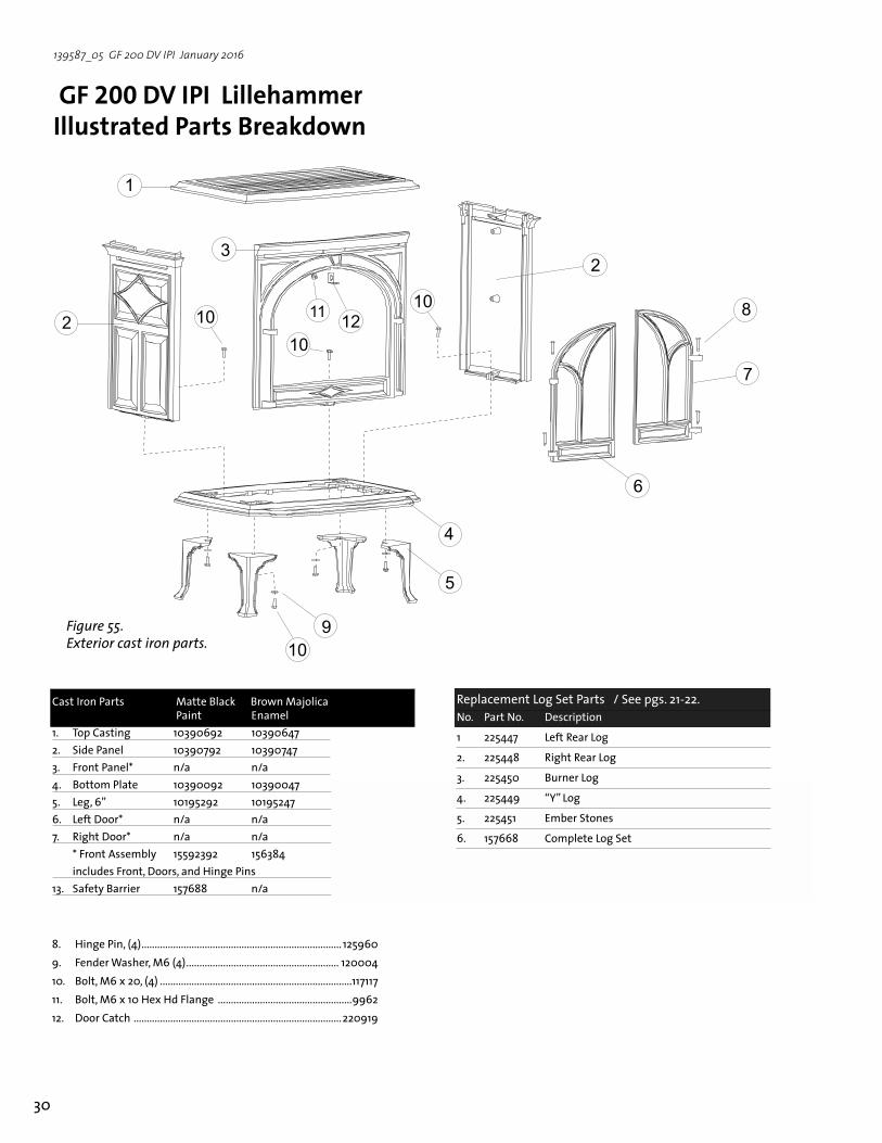
GF 200 DV IPI Lillehammer Illustrated Parts Breakdown
Cast Iron Parts Matte Black Brown Majolica Paint Enamel 1. Top Casting 10390692 10390647 2. Side Panel 10390792 10390747 3. Front Panel* n/a n/a 4. Bottom Plate 10390092 10390047 5. Leg, 6” 10195292 10195247 6. Left Door* n/a n/a7. Right Door* n/a n/a * Front Assembly 15592392 156384 includes Front, Doors, and Hinge Pins13. Safety Barrier 157688 n/a
�
�
�
�
�
�
�
�
�
����
��
��
���
��
8. Hinge Pin, (4) ............................................................................ 1259609. Fender Washer, M6 (4) .......................................................... 12000410. Bolt, M6 x 20, (4) .........................................................................11711711. Bolt, M6 x 10 Hex Hd Flange ...................................................996212. Door Catch ...............................................................................220919
Figure 55. Exterior cast iron parts.
Replacement Log Set Parts / See pgs. 21-22.No. Part No. Description
1 225447 Left Rear Log
2. 225448 Right Rear Log
3. 225450 Burner Log
4. 225449 “Y” Log
5. 225451 Ember Stones
6. 157668 Complete Log Set

31
139587_05 GF 200 DV IPI January 2016
No. Part No. Description
1. 117917 Screw, #8 x 1/2” SL Blk Oxide
2. 117921 Screw, Pan Hd Ph M4 x 12mm Blk Oxide
3. 117922 Nut, Hex M4 DIN 934 PLAIN
4. 117975 Nut, Wing M6, Zinc
5. 117999 Screw, SL SMA Type B #8 x 3/8 Zinc
6. 118029 Washer, Fender .250 x 1.50 dia.
7. 118033 Bolt, M6 x 130 Hex Hd
8. 118039 Spacer, .375 OD x 1.188
9. 118040 Spacer, Control Door Hinge .375 OD x 3.172
10. 118214 Screw, #8x 1/4” Taptite
11. 118257 Hook & Loop Tape, 1” Wide, Self-adhesive
12. 220614 Terminal Block, 2 Pole 77 Series
13. 22093192 Control Door GF 200 DV IPI
14. 221185 Orifice, 1.20 mm
225441 Orifice, 2.1mm
15. 222280 Gasket, Drop-in Orifice Holder
16. 222292 Elbow, 90 deg, Brass 3/8 NTP x 3/8” dia. flare
Figure 56. GF 200 DV IPI Valve Assembly and DFC Components.
No. Part No. Description
17. 222924 Proflame 1 IPI Ignition Board
18. 223231 Orifice Holder, Drop-in Assembly
19. 224262 Battery Box w/ Cover
20. 224952 Instruction Label, Control Door - GF IPI Series
21. 224972 Valve, NG, Proflame Manual, 50%TD, SIT
22. 225088 Bracket, DFC
23. 225089 Terminal Block Bracket
24. 225432 Valve Bracket
25. 225433 Wire Retainer Bracket
26. 157683 Wire Harness, Proflame 1, Replacement
27.* 225422 AC/DC Adapter, High Temp - 7V
���
�������
���
���
������
���
���
* not illustrated

32
139587_05 GF 200 DV IPI January 2016
1. 117917 Screw 8 x 12 1/2 SL Blk Oxide 2. 22544092 Rear Cover, Burner Skirt
3. 225081 Burner Skirt
4. 157651 Burner Assembly Complete
5. 225077 Bracket, Burner Retainer
6. 221390 Primary Air Shutter
7. 225080 Handle, Air Shutter
8. 220734 Gasket, 2.25in OD x .125
9. 117975 Wing Nut M6, Zinc
10. 225092 Air Deflector, Burner Skirt
11. 225439 Pilot Shield, High Wind (Optional Kit 157685)
12. 225438 Pilot Shield
13. 224785 Pilot, NG/LP, Dual-Fuel Convertible Flame Hood
14. 118218 Screw, HWH SMA 8 x 1.5
15. 224791 Spacer, PSE Pilot, .188”
16. 129670 Gasket, Pilot Assembly
17. 22508292 Firebox Baffle
18. 225434 Secondary Air Diverter
19. 9962 Bolt, Hex Cap M6x10 DIN Ser Flange Blk
No. Part No. Description No. Part No. Description
Figure 57. GF 200 DV IPI Pilot & Burner assembly and associated hardware.
��
�
��
��
��
��
��
�� ��
�
��
�
�
�
���
�
�
�
�
��
��

33
139587_05 GF 200 DV IPI January 2016
��
�
�
�
Figure 59. GF 200 DV IPI Glass Assembly
GF 200 DV IPI Accessories Description Part No.
Remote Control 224910
Wall Thermostat 750003
Blower Kit 155631
Screen 155641
Brick Panel Kit 157666
Long Leg Kit (8 1/4”) / Matte Black 154929
Long Leg Kit (8 1/4”) / Brown Majolica Enamel 351149
Leg Leveler 156096
Fuel Conversion Kit, Propane 157669
Fuel Conversion Kit, Natural Gas 157670
High Altitude Adjustment Kit / LP 157675
High Altitude Adjustment Kit / NG 157676
Vertical Vent Adaptor Kit, 5/8-to-4/6 157674
High Wind Pilot Shield Kit 157685
No. Part No. Description
1. 22136592 Glass Frame II
2. 129124 Gasket, Tadpole - .25 dia. x 1.25”, 6 ft.
3. 220576 Glass Panel, Ceramic
4. 220042 Replacement Glass Clips
5. 155599 Replacement Glass Kit, GF 200 DV IPI
Figure 58. GF 200 DV IPI Rear Components
No. Part No. Description
1. 22542492 Switch Cover
2. 129775 Gasket,
3. 225086 Bracket, Rear Shroud
4. 22508592 Rear Shroud
5. 129784 Adaptor, 8 in. dia.
6. 117917 Screw, #8 x 1/2 in. Blk. Oxcide
7. 225437 Decal, Switch ID
8. 220703 Switch, Rocker, SPDT - Center Off, Blk.
9. 120517 Switch, Rocker, SPST, Blk.
10. 22542692 Wall Shield
11. 129774 Gasket, 5 in. dia.
12. 129782 Adaptor, 5 in.
13. 129781 Adaptor, 4 in. (Custom)
14. 129783 Adaptor, 6 5/8 in. (Custom)
15. 157674 Vertical Vent Adaptor Kit, 5/8-to-4/6
16. 157684 Wire Harness, Controls - GF 200 DV IPI

34
139587_05 GF 200 DV IPI January 2016
Effective January 1, 2013
This warranty policy applies to gas products identified by Jøtul, Scan, and Atra trade names, as set forth below.A. LIMITED FIVE YEAR WARRANTY - Cast Iron, Steel Doors, Surround Components, Firebox:Jøtul North America Inc. (JØTUL) warrants, to the original retail purchaser, that those components of the Jøtul, Scan, or Atra Gas Stove or Fireplace specified above will be free of defects in material and workmanship for a period of five (5) years from the date of purchase. This warranty is subject to the terms, exclusions and limitations set forth in the following text.B. LIMITED TWO YEAR WARRANTY - Burner, Burner Treatments, Firebox Panels: JØTUL warrants, to the original retail purchaser, that those components of the Jøtul, Scan, or Atra Gas Stove or Fireplace specified above will be free of defects in material and workmanship for a period of two (2) years from the date of purchase. This warranty is subject to the terms, exclusions, and limitations set forth in the following text.C. LIMITED TWO YEAR WARRANTY - Enamel Finish: JØTUL warrants, to the original retail purchaser, the enamel finish on cast iron components of the Jøtul Stove or Fireplace Insert specified above against peeling or fading for a period of two (2) years from the date of purchase. This warranty is subject to the terms, exclusions and limitations set forth below.D. LIMITED ONE YEAR WARRANTY - Gas & Electrical Components (controls, plumbing, valve, blower): JØTUL warrants, to the original retail purchaser, that those components of the Jøtul, Scan, or Atra Gas Stove or Fireplace specified above will be free of defects in material and workmanship for a period of one (1) year from the date of purchase. This warranty is subject to the terms, exclusions, and limitations set forth in the following text.
JØTUL will repair or replace (including parts & labor), at its option, any of the above components determined by JØTUL to be covered by this warranty. You must, at your own expense, arrange to deliver or ship the component to an authorized Jøtul, Scan, or Atra dealer and arrange for pickup or delivery of the component after repairs have been made. If, upon inspection, JØTUL determines that the component is covered by this warranty, the repair or replacement will be made as set forth above. This warranty is not transferable and is extended only to, and is solely for the benefit of, the original retail purchaser of the Jøtul, Scan, or Atra Gas Stove or Fireplace. This paragraph sets forth the sole remedy available under this warranty in the event of any defect in the Jøtul, Scan, or Atra Gas Stove or Fireplace.The warranty period for any replaced component will be the remaining unexpired portion of the warranty period for the original component.Please retain your dated sales receipt in your records as proof of purchase. EXCLUSIONS AND LIMITATIONSNOTICE: This warranty is void if installation or service is performed by someone other than an authorized installer, service agency or gas supplier, or if installation is not in conformance with the installation and operating instructions contained in this owner’s manual or local and/or national fire and building regulations. A listing of local authorized installers, service agencies and gas suppliers can be obtained from the National Fireplace Institute at http://www.nficertified.org/.
This warranty does not cover the following:1) Repair or replacement of parts that are subject to normal wear and tear during the warranty period or to parts that may require replacement in connection with normal maintenance. These parts include gaskets and glass (except to the extent such parts suffer damage from thermal stress).2) Damage due to incorrect installations not in conformance with the installation instructions contained in this owner’s manual or local and/or national fire and building regulations.3) Damage due to service performed by an installer, service agency or gas supplier, unless otherwise agreed to in writing by JØTUL. 4) Labor or other costs associated with the repair of gas controls, plumbing, burners, log set, or sheet metal firebox beyond the warranty period.5) Damage caused by unauthorized modification, use or repair.6) Damage to enameled surfaces caused by improper operation or misuse, including use that is not in conformance with the operating instructions contained in this owner’s manual. Such damage can typically be identified by bubbling, cracking, or discoloration of the enamel finish.7) Costs incurred by travel time and/or loss of service.8) Damage incurred while the Jøtul, Scan, or Atra Gas Stove or Fireplace is in transit.IN NO EVENT SHALL JØTUL, ITS PARENT COMPANY, SHAREHOLDERS, AFFILIATES, OFFICERS, EMPLOYEES, AGENTS OR REPRESENTATIVES BE LIABLE OR RESPONSIBLE TO YOU FOR ANY SPECIAL, INDIRECT, INCIDENTAL, CONSEQUENTIAL, PUNITIVE OR OTHER SIMILAR DAMAGES, INCLUDING, BUT NOT LIMITED TO, LOST PROFITS, LOST SALES, INJURY TO PERSON OR PROPERTY, OR DAMAGES TO A STRUCTURE OR ITS CONTENTS, ARISING UNDER ANY THEORY OF LAW WHATSOEVER. ALL IMPLIED WARRANTIES, INCLUDING THE IMPLIED WARRANTIES OF MERCHANTABILITY AND FITNESS FOR A PARTICULAR PURPOSE, OR OTHERWISE, ARE LIMITED IN DURATION TO THE LENGTH OF THIS WRITTEN WARRANTY. EXCEPT AS EXPRESSLY SET FORTH HEREIN, JØTUL MAKES NO ORAL, WRITTEN OR OTHER WARRANTY WITH RESPECT TO JØTUL, SCAN OR ATRA GAS STOVES OR FIREPLACES.Some states do not allow the exclusion or limitation of incidental or consequential damages, or limitations on the length of implied warranties. Therefore, the above exclusions or limitations may not apply to you. This warranty gives you specific legal rights, and you may have other rights, which vary from state to state. JØTUL reserves the right to discontinue, modify or change the materials used to produce the Jøtul, Scan, or Atra Gas Stove or Fireplace. JØTUL shall have the right to replace any defective component with substitute components determined by JØTUL to be of substantially equal quality and price. The dollar value of JØTUL’s liability for breach of this warranty shall be limited exclusively to the cost of furnishing a replacement component. JØTUL shall not in any event be liable for the cost of labor expended by others in connection with any defective component. Any costs or expenses beyond those expressly assumed by JØTUL under the terms of this warranty shall be the sole responsibility of the owner(s) of the Jøtul, Scan, or Atra Gas Stove or Fireplace.No dealer, distributor, or other person is authorized to modify, augment, or extend this limited warranty on behalf of JØTUL. NO MODIFICATION OR CHANGE TO THIS WARRANTY WILL BE EFFECTIVE UNLESS IT IS MADE IN A WRITTEN DOCUMENT MANUALLY SIGNED BY AN AUTHORIZED OFFICER OF JØTUL.An authorized installer may have been provided with certain information related particularly to the Jøtul, Scan, or Atra Gas Stove or Fireplace; however, no authorized installer or other person who may service the appliance is an agent of JØTUL. No inference should be made that JØTUL has tested, certified, or otherwise pronounced any person as qualified to install or service the appliance. JØTUL shall not be liable or otherwise responsible for any error or omission by a person installing or servicing a Jøtul, Scan, or Atra Gas Stove or Fireplace.If you believe your Jøtul, Scan, or Atra Gas Stove or Fireplace is defective, you should contact your nearest authorized Jøtul, Scan, or Atra dealer, who will process a warranty claim. IN ORDER TO QUALIFY FOR WARRANTY COVERAGE, JØTUL MUST RECEIVE NOTICE OF A POSSIBLE DEFECT WITHIN SIXTY (60) DAYS OF THE DATE THE DEFECT IS FIRST DISCOVERED, OR REASONABLY COULD HAVE BEEN DISCOVERED.
This warranty is given by Jøtul North America, Inc., 55 Hutcherson Drive, Gorham, Maine 04038 USA
Jøtul Gas Product Limited Lifetime Warranty

35
139587_05 GF 200 DV IPI January 2016
WARNING: IF YOU DO NOT FOLLOW THESE INSTRUCTIONS EXACTLY, A FIRE OR EXPLOSION MAY RESULT
CAUSING PROPERTY DAMAGE, PERSONAL INJURY, OR LOSS OF LIFE.
A. This appliance is equipped with an ignition device which automatically lights the pilot. Do Not try to light the pilot by hand.
B. BEFORE LIGHTING, smell all around the appliance area for gas. Be sure to smell next to the floor because some gas is heavier than air and will settle to the floor.
WHAT TO DO IF YOU SMELL GAS: • Extinguish any open flame • Open windows. • Do not light this or any other appliance. • Do not touch any electrical switches. • Do not use any phone in your building. • Immediately call your gas supplier from a neighbor’s phone. • If your gas supplier cannot be reached, call the fire department.
C. Use only your hand to turn the gas control knob. Never use tools. If the knob will not turn by hand, do not try to force it or repair it. Call a qualified technician. Force or attempted repair may result in a fire or explosion.
D. Do not use this appliance if any part has been under water. Immediately call a qualified ser-vice technician to inspect the appliance and to replace any part of the control system and any gas control which has been under water.
LIGHTING INSTRUCTIONSFOR YOUR SAFETY, READ BEFORE LIGHTING.
1. Set the thermostat to the lowest setting.2. Turn off all electric power to the appliance if
service is to be performed.
3. Set the Burner switch to the “OFF” position.4. Close control access door.
TO TURN OFF GAS TO THE APPLIANCE
1. STOP! Read the safety information above.2. Set the thermostat, if equipped, to the lowest
setting.3. Set the Burner switch to the “OFF” position.4. This appliance is equipped with an ignition
device which automatically lights the pilot. Do not try to light the pilot by hand.
5. Wait five (5) minutes to clear out any gas. Then smell for gas, including near the floor.
If you smell gas, STOP! Follow “B” in the safety information above on this label. If you do not smell gas, go to the next step.
6. Set the Pilot Mode switch to CPI for continuous operation. The pilot will light. Set Pilot to IPI for intermitent operation. The pilot will light when there is a call for heat.
7. Set the Burner switch to the “ON” or “T-STAT” position.
8. Set the thermostat to the desired setting to light the burner. If the appliance will not oper-ate, follow the instructions ”To Turn Off Gas To Appliance”, and call your service technician or gas supplier.
OPERATING INSTRUCTIONS
Pilot Controls
PILOT ASSEMBLY
Burner Controls
���
���
��
����
���
������
���
��

36
139587_05 GF 200 DV IPI January 2016
Jøtul North America55 Hutcherson Dr. Gorham, Maine 04038-2634
Jøtul ASAP.O. Box 1411N-1602 Fredrikstad
Norway
www.jotul.us
This appliance must be installed in conformance with local and national building regulations. Before beginning the installation, it is important that these instructions be carefully read and understood. Jøtul maintains a policy of continual product development. Consequently, products may differ in specification, color or type of accessories from those illustrated or described in various publications.
January 2016
139587_05