Embed Size (px)
Citation preview
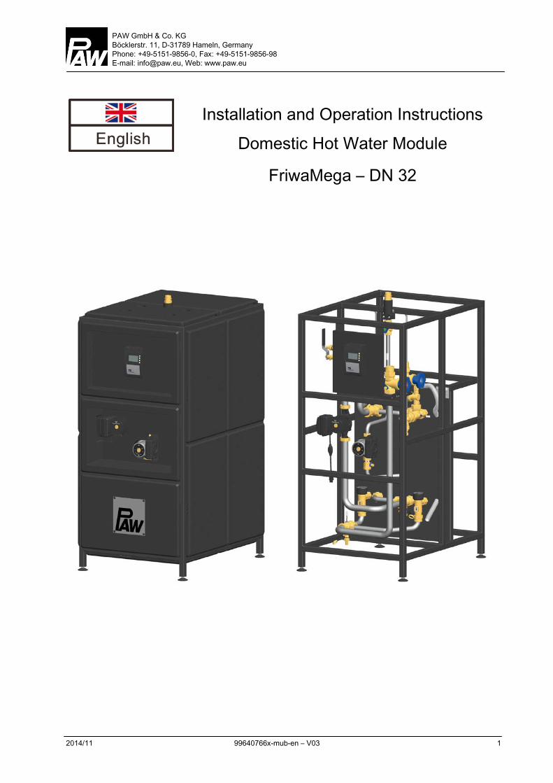
PAW GmbH & Co. KG Böcklerstr. 11, D-31789 Hameln, Germany Phone: +49-5151-9856-0, Fax: +49-5151-9856-98 E-mail: [email protected], Web: www.paw.eu
2014/11 99640766x-mub-en – V03 1
Installation and Operation Instructions Domestic Hot Water Module
FriwaMega – DN 32
1 General Information
2 99640766x-mub-en – V03 2014/11
Item no. 99640766x-mub-en - Version V03 – Date 2014/11
Translation of the original instructions
We reserve the right to make technical changes without notice!
Printed in Germany – Copyright by PAW GmbH & Co. KG
PAW GmbH & Co.KG
Böcklerstraße 11
D-31789 Hameln, Germany
1 General Information
2014/11 99640766x-mub-en – V03 3
Contents
1 General Information ......................................................................................................... 4
1.1 Scope of these instructions .......................................................................................... 4
1.2 About this product ........................................................................................................ 5
1.3 Designated use ............................................................................................................ 5
2 Safety instructions ........................................................................................................... 6
3 Product description .......................................................................................................... 8
4 Dimensioning and planning ............................................................................................ 10
4.1 Dimensioning of the tank ............................................................................................ 11
5 Circulation mode ........................................................................................................... 12
6 Assembly and installation [specialist] .............................................................................. 13
7 Commissioning [specialist] ............................................................................................. 16
7.1 Filling the primary circuit ............................................................................................. 17
7.2 Commissioning of the controller ................................................................................. 18
7.3 Maximum withdrawal flow rate ................................................................................... 20
7.4 Setting the temperature .............................................................................................. 22
8 Maintenance [specialist] ................................................................................................. 23
9 Spare parts [specialist] .................................................................................................. 24
9.1 Control and insulation ................................................................................................. 24
9.2 Hydraulics primary circuit (6407660, 6407661, 6407662) ........................................... 25
9.3 Hydraulics secondary circuit FriwaMega without circulation (6407660) ...................... 26
9.4 Hydraulics secondary circuit FriwaMega with circulation (6407661, 6407662)............ 27
10 Technical data ............................................................................................................... 28
10.1 Pressure drop characteristics ..................................................................................... 29
11 Commissioning report .................................................................................................... 30
1 General Information
4 99640766x-mub-en – V03 2014/11
1 General Information
1.1 Scope of these instructions
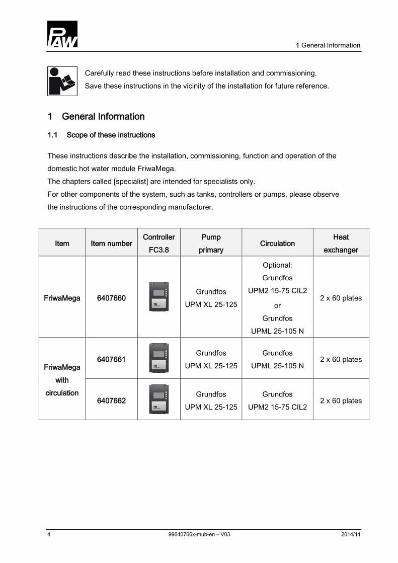
These instructions describe the installation, commissioning, function and operation of the domestic hot water module FriwaMega. The chapters called [specialist] are intended for specialists only. For other components of the system, such as tanks, controllers or pumps, please observe the instructions of the corresponding manufacturer.
Item Item number Controller
FC3.8 Pump
primary Circulation
Heat exchanger
FriwaMega 6407660
Grundfos UPM XL 25-125
Optional: Grundfos
UPM2 15-75 CIL2
or Grundfos
UPML 25-105 N
2 x 60 plates
FriwaMega with
circulation
6407661
Grundfos UPM XL 25-125
Grundfos UPML 25-105 N
2 x 60 plates
6407662
Grundfos UPM XL 25-125
Grundfos UPM2 15-75 CIL2
2 x 60 plates
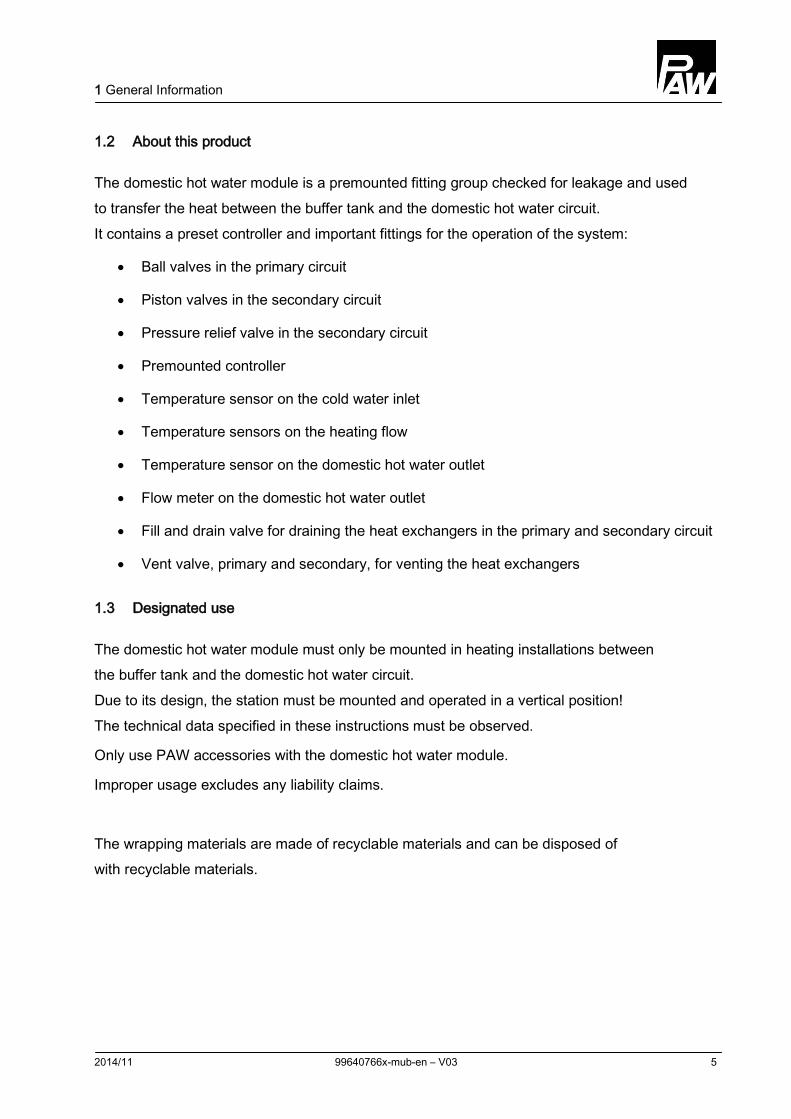
Carefully read these instructions before installation and commissioning. Save these instructions in the vicinity of the installation for future reference.
1 General Information
2014/11 99640766x-mub-en – V03 5
1.2 About this product
The domestic hot water module is a premounted fitting group checked for leakage and used to transfer the heat between the buffer tank and the domestic hot water circuit. It contains a preset controller and important fittings for the operation of the system:
• Ball valves in the primary circuit
• Piston valves in the secondary circuit
• Pressure relief valve in the secondary circuit
• Premounted controller
• Temperature sensor on the cold water inlet
• Temperature sensors on the heating flow
• Temperature sensor on the domestic hot water outlet
• Flow meter on the domestic hot water outlet
• Fill and drain valve for draining the heat exchangers in the primary and secondary circuit
• Vent valve, primary and secondary, for venting the heat exchangers
1.3 Designated use
The domestic hot water module must only be mounted in heating installations between the buffer tank and the domestic hot water circuit. Due to its design, the station must be mounted and operated in a vertical position! The technical data specified in these instructions must be observed.
Only use PAW accessories with the domestic hot water module.
Improper usage excludes any liability claims.
The wrapping materials are made of recyclable materials and can be disposed of with recyclable materials.
2 Safety instructions
6 99640766x-mub-en – V03 2014/11
2 Safety instructions
The installation and commissioning as well as the connection of electrical components require technical knowledge commensurate with a recognised vocational qualification as a fitter for plumbing, heating and air conditioning technology, or a profession requiring a comparable level of knowledge [specialist]. The following must be observed during installation and commissioning:
• relevant local and national regulations
• accident prevention regulations of the professional association
• instructions and safety instructions of this manual
WARNING Danger of scalding due to hot water!
Undesirable circulation of water in the primary circuit can cause the exit of water of up to 90 °C at the withdrawal point.
External pumps must not be installed between the service water module and the buffer tank.
The domestic hot water module must not be connected to a distribution manifold.
CAUTION Risk of burns!
The valves, fittings and the pump may heat up to more than 95 °C during operation.
The insulating shell must remain closed during operation.
2 Safety instructions
2014/11 99640766x-mub-en – V03 7
NOTICE Material damage due to mineral oils!
Mineral oil products cause lasting damage to seals made of EPDM, whereby the sealant properties get lost. We do not assume liability nor provide warranty for damage to property resulting from sealants damaged in this way.
It is imperative to avoid that EPDM gets in contact with substances containing mineral oils.
Use a lubricant based on silicone or polyalkylene and free of mineral oils, such as Unisilikon L250L and Syntheso Glep 1 of the Klüber company or a silicone spray.
NOTICE Malfunction!
The domestic hot water module must be integrated in the potential equalisation of the electric installation. This can be guaranteed by establishing a potential equalisation connection to the main potential connection according to regulations or by the connected pipe system.
3 Product description
8 99640766x-mub-en – V03 2014/11
3 Product description
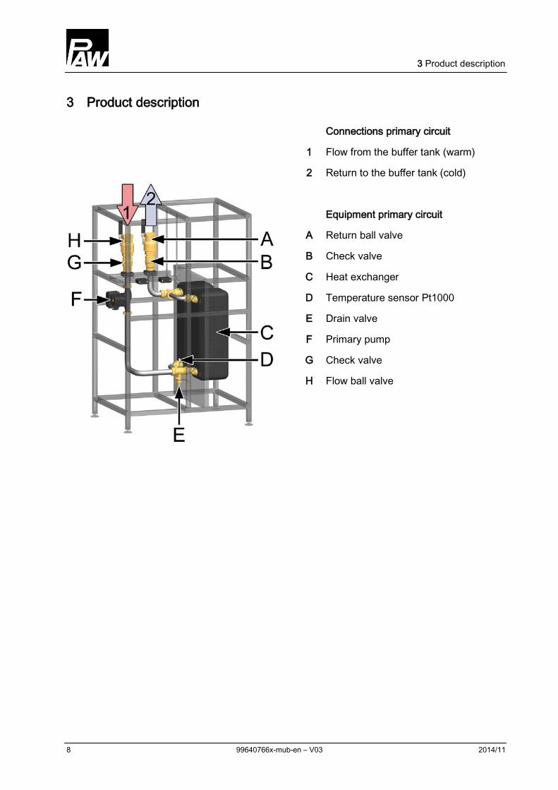
Connections primary circuit
1 Flow from the buffer tank (warm)
2 Return to the buffer tank (cold)
Equipment primary circuit
A Return ball valve
B Check valve
C Heat exchanger
D Temperature sensor Pt1000
E Drain valve
F Primary pump
G Check valve
H Flow ball valve
3 Product description
2014/11 99640766x-mub-en – V03 9
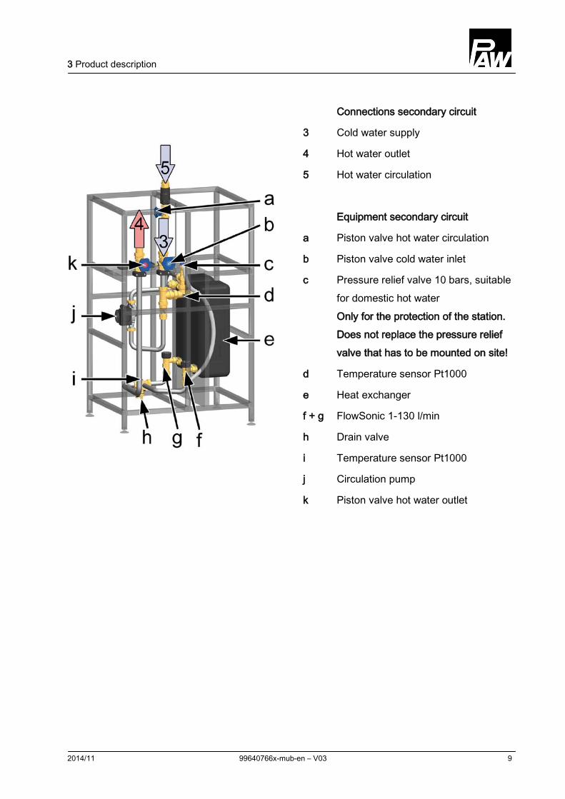
Connections secondary circuit
3 Cold water supply
4 Hot water outlet
5 Hot water circulation
Equipment secondary circuit
a Piston valve hot water circulation
b Piston valve cold water inlet
c Pressure relief valve 10 bars, suitable for domestic hot water Only for the protection of the station. Does not replace the pressure relief valve that has to be mounted on site!
d Temperature sensor Pt1000
e Heat exchanger
f + g FlowSonic 1-130 l/min
h Drain valve
i Temperature sensor Pt1000
j Circulation pump
k Piston valve hot water outlet
4 Dimensioning and planning
10 99640766x-mub-en – V03 2014/11
4 Dimensioning and planning
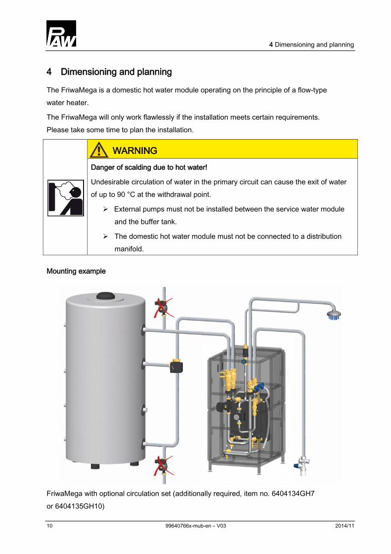
The FriwaMega is a domestic hot water module operating on the principle of a flow-type water heater.
The FriwaMega will only work flawlessly if the installation meets certain requirements. Please take some time to plan the installation.
WARNING Danger of scalding due to hot water!
Undesirable circulation of water in the primary circuit can cause the exit of water of up to 90 °C at the withdrawal point.
External pumps must not be installed between the service water module and the buffer tank.
The domestic hot water module must not be connected to a distribution manifold.
Mounting example
FriwaMega with optional circulation set (additionally required, item no. 6404134GH7 or 6404135GH10)
4 Dimensioning and planning
2014/11 99640766x-mub-en – V03 11
4.1 Dimensioning of the tank
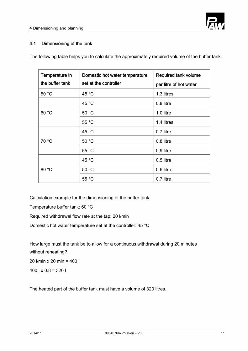
The following table helps you to calculate the approximately required volume of the buffer tank.
Temperature in the buffer tank
Domestic hot water temperature set at the controller
Required tank volume
per litre of hot water
50 °C 45 °C 1.3 litres
60 °C
45 °C 0.8 litre
50 °C 1.0 litre
55 °C 1.4 litres
70 °C
45 °C 0.7 litre
50 °C 0.8 litre
55 °C 0,9 litre
80 °C
45 °C 0.5 litre
50 °C 0.6 litre
55 °C 0.7 litre
Calculation example for the dimensioning of the buffer tank:
Temperature buffer tank: 60 °C
Required withdrawal flow rate at the tap: 20 l/min
Domestic hot water temperature set at the controller: 45 °C
How large must the tank be to allow for a continuous withdrawal during 20 minutes without reheating?
20 l/min x 20 min = 400 l
400 l x 0.8 = 320 l
The heated part of the buffer tank must have a volume of 320 litres.
5 Circulation mode
12 99640766x-mub-en – V03 2014/11
5 Circulation mode
The domestic hot water module is optionally equipped with a circulation pump.
The FriwaMega without circulation can be subsequently equipped with a circulation set (item no. 6404134GH7 or 6404135GH10) for an internal retrofitting.
Three different operating modes of the circulation pump are set at the controller (see controller instructions, menu "Func" / "F02"):
• Pulse-controlled operation (depending on the demand / requirements):
The short opening of a hot water tap (tap pulse: ~2 sec.) starts the circulation pump. The circulation pump will then run for several minutes (adjustable).
• Time-dependent operation:
The operation of the circulation pump can be set on a week clock within a freely selectable period of time. The circulation will start at the beginning of the period of time chosen. The circulation will stop after the end of the chosen period of time.
• Temperature-dependent operation:
In this operating mode, the circulation only starts if the adjustable minimum temperature on the circulation temperature sensor is not reached during the chosen period of operation. The circulation stops after the required temperature has been reached or after the end of the chosen period of time.
The operating modes can be combined with one another as wished, f. ex. the time- and the temperature-dependent operating modes. The circulation is only active if the temperature at the circulation temperature sensor falls below the required value and if the time window is active.
Outside the time window, the circulation pump can be started by a tap pulse if the pulse-controlled operation mode is additionally activated.
NOTICE Damage to property!
When the Friwa is delivered, the circulation is not activated (see controller instructions, menu: "Func" / "F02" set to "OFF"). Once the circulation line mounted, it is mandatory to select and preset the operating mode. The revolution speed of the circulation pump must be determined by the PWM signal (factory setting: 40 %).
6 Assembly and installation [specialist]
2014/11 99640766x-mub-en – V03 13
6 Assembly and installation [specialist]
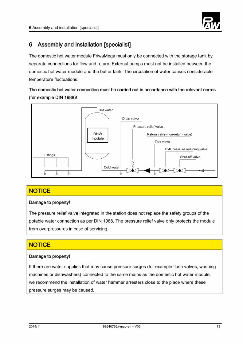
The domestic hot water module FriwaMega must only be connected with the storage tank by separate connections for flow and return. External pumps must not be installed between the domestic hot water module and the buffer tank. The circulation of water causes considerable temperature fluctuations.
The domestic hot water connection must be carried out in accordance with the relevant norms (for example DIN 1988)!
NOTICE
Damage to property!
The pressure relief valve integrated in the station does not replace the safety groups of the potable water connection as per DIN 1988. The pressure relief valve only protects the module from overpressures in case of servicing.
NOTICE
Damage to property!
If there are water supplies that may cause pressure surges (for example flush valves, washing machines or dishwashers) connected to the same mains as the domestic hot water module, we recommend the installation of water hammer arresters close to the place where these pressure surges may be caused.
DHW module
Fittings
Drain valve
Pressure relief valve
Return valve (non-return valve)
Evtl. pressure reducing valve
Test valve
Shut-off valve
Hot water
Cold water
6 Assembly and installation [specialist]
14 99640766x-mub-en – V03 2014/11
WARNING Risk to life and limb due to electric shock!
Prior to commencing electrical work on the controller, pull the mains plug!
Only after completing all installation work, plug the mains plug of the controller into a socket. Thus, an unintentional start of the motors is avoided.
NOTICE Damage to property!
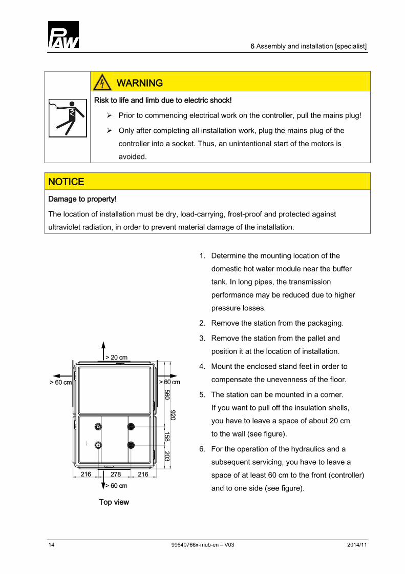
The location of installation must be dry, load-carrying, frost-proof and protected against ultraviolet radiation, in order to prevent material damage of the installation.
Top view
1. Determine the mounting location of the domestic hot water module near the buffer tank. In long pipes, the transmission performance may be reduced due to higher pressure losses.
2. Remove the station from the packaging.
3. Remove the station from the pallet and position it at the location of installation.
4. Mount the enclosed stand feet in order to compensate the unevenness of the floor.
5. The station can be mounted in a corner. If you want to pull off the insulation shells, you have to leave a space of about 20 cm to the wall (see figure).
6. For the operation of the hydraulics and a subsequent servicing, you have to leave a space of at least 60 cm to the front (controller) and to one side (see figure).
6 Assembly and installation [specialist]
2014/11 99640766x-mub-en – V03 15
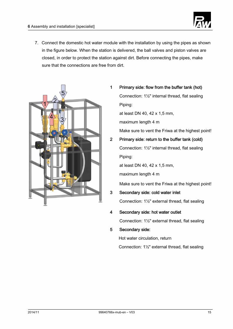
7. Connect the domestic hot water module with the installation by using the pipes as shown in the figure below. When the station is delivered, the ball valves and piston valves are closed, in order to protect the station against dirt. Before connecting the pipes, make sure that the connections are free from dirt.
1 Primary side: flow from the buffer tank (hot)
Connection: 1½" internal thread, flat sealing
Piping:
at least DN 40, 42 x 1,5 mm,
maximum length 4 m
Make sure to vent the Friwa at the highest point!
2 Primary side: return to the buffer tank (cold)
Connection: 1½" internal thread, flat sealing
Piping:
at least DN 40, 42 x 1,5 mm,
maximum length 4 m
Make sure to vent the Friwa at the highest point!
3 Secondary side: cold water inlet
Connection: 1½" external thread, flat sealing
4 Secondary side: hot water outlet
Connection: 1½" external thread, flat sealing
5 Secondary side:
Hot water circulation, return
Connection: 1½" external thread, flat sealing
7 Commissioning [specialist]
16 99640766x-mub-en – V03 2014/11
7 Commissioning [specialist]
Note!
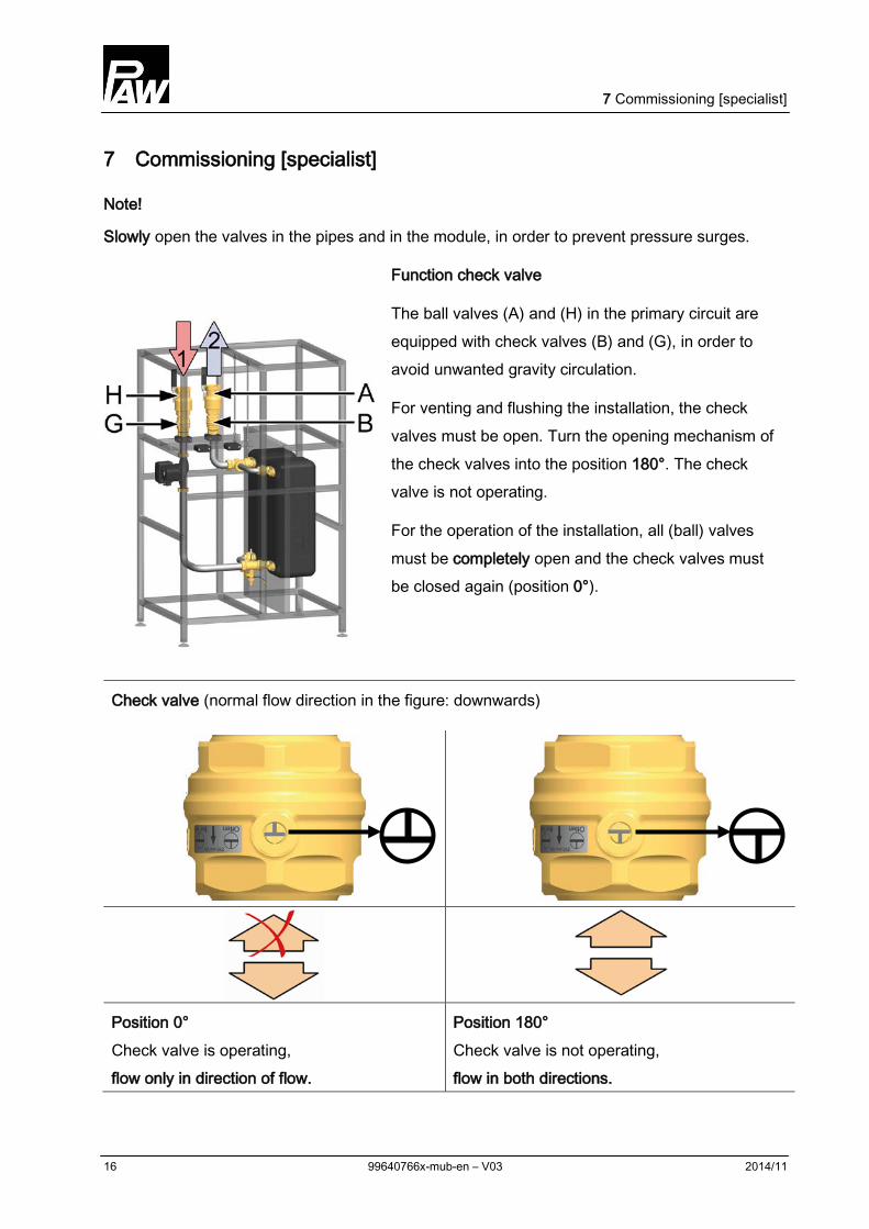
Slowly open the valves in the pipes and in the module, in order to prevent pressure surges.
Function check valve
The ball valves (A) and (H) in the primary circuit are equipped with check valves (B) and (G), in order to avoid unwanted gravity circulation.
For venting and flushing the installation, the check valves must be open. Turn the opening mechanism of the check valves into the position 180°. The check valve is not operating.
For the operation of the installation, all (ball) valves must be completely open and the check valves must be closed again (position 0°).
Check valve (normal flow direction in the figure: downwards)
Position 0° Check valve is operating, flow only in direction of flow.
Position 180° Check valve is not operating, flow in both directions.
7 Commissioning [specialist]
2014/11 99640766x-mub-en – V03 17
7.1 Filling the primary circuit
WARNING Danger of scalding due to hot water!
The system is under pressure. By opening the pressure relief valve, hot water with a temperature of up to 90 °C may exit and cause personal injury.
Open the pressure relief valve slowly and with sufficient distance.
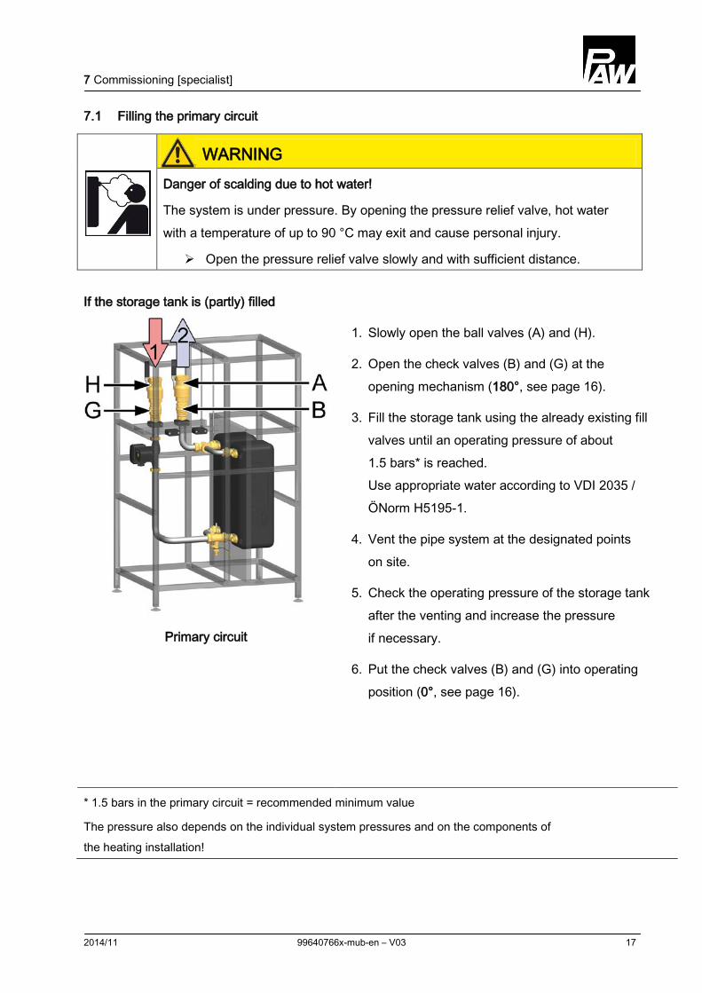
If the storage tank is (partly) filled
Primary circuit
1. Slowly open the ball valves (A) and (H).
2. Open the check valves (B) and (G) at the opening mechanism (180°, see page 16).
3. Fill the storage tank using the already existing fill valves until an operating pressure of about 1.5 bars* is reached. Use appropriate water according to VDI 2035 / ÖNorm H5195-1.
4. Vent the pipe system at the designated points on site.
5. Check the operating pressure of the storage tank after the venting and increase the pressure if necessary.
6. Put the check valves (B) and (G) into operating position (0°, see page 16).
* 1.5 bars in the primary circuit = recommended minimum value
The pressure also depends on the individual system pressures and on the components of the heating installation!
7 Commissioning [specialist]
18 99640766x-mub-en – V03 2014/11
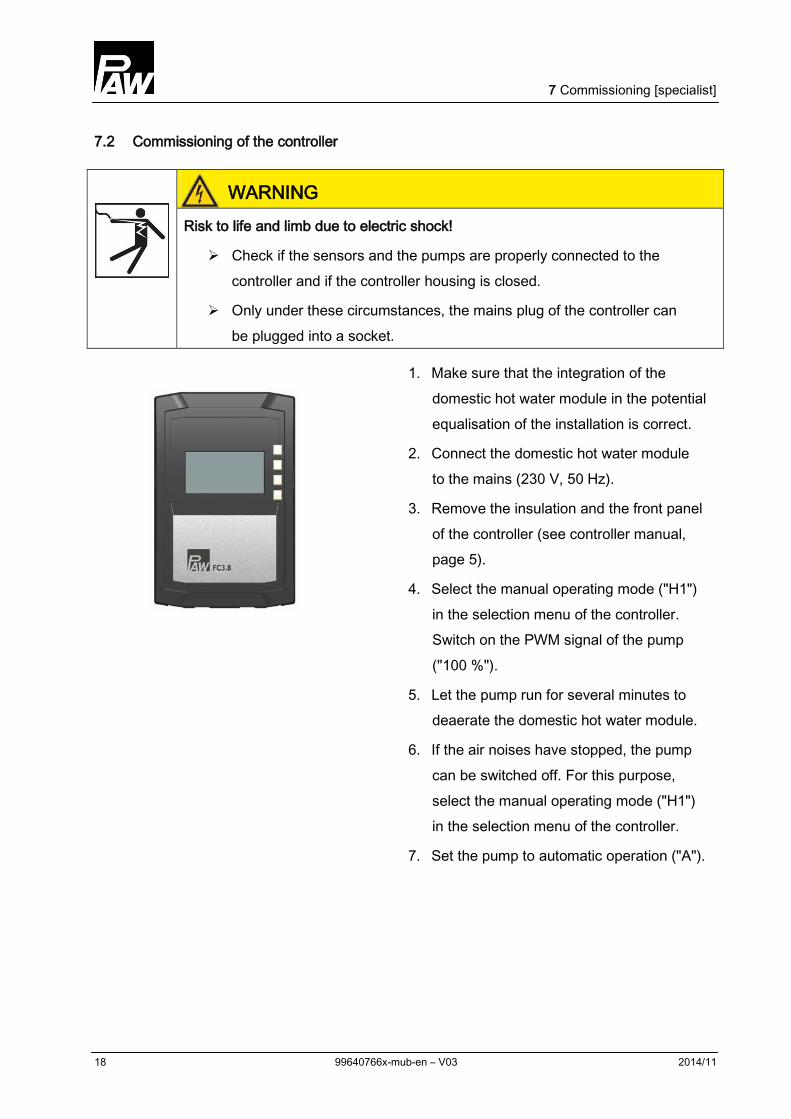
7.2 Commissioning of the controller
WARNING Risk to life and limb due to electric shock!
Check if the sensors and the pumps are properly connected to the controller and if the controller housing is closed.
Only under these circumstances, the mains plug of the controller can be plugged into a socket.
1. Make sure that the integration of the domestic hot water module in the potential equalisation of the installation is correct.
2. Connect the domestic hot water module to the mains (230 V, 50 Hz).
3. Remove the insulation and the front panel of the controller (see controller manual, page 5).
4. Select the manual operating mode ("H1") in the selection menu of the controller. Switch on the PWM signal of the pump ("100 %").
5. Let the pump run for several minutes to deaerate the domestic hot water module.
6. If the air noises have stopped, the pump can be switched off. For this purpose, select the manual operating mode ("H1") in the selection menu of the controller.
7. Set the pump to automatic operation ("A").
7 Commissioning [specialist]
2014/11 99640766x-mub-en – V03 19
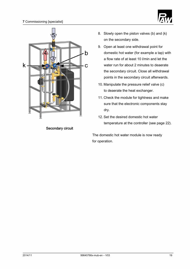
Secondary circuit
8. Slowly open the piston valves (b) and (k) on the secondary side.
9. Open at least one withdrawal point for domestic hot water (for example a tap) with a flow rate of at least 10 l/min and let the water run for about 2 minutes to deaerate the secondary circuit. Close all withdrawal points in the secondary circuit afterwards.
10. Manipulate the pressure relief valve (c) to deaerate the heat exchanger.
11. Check the module for tightness and make sure that the electronic components stay dry.
12. Set the desired domestic hot water temperature at the controller (see page 22).
The domestic hot water module is now ready for operation.
7 Commissioning [specialist]
20 99640766x-mub-en – V03 2014/11
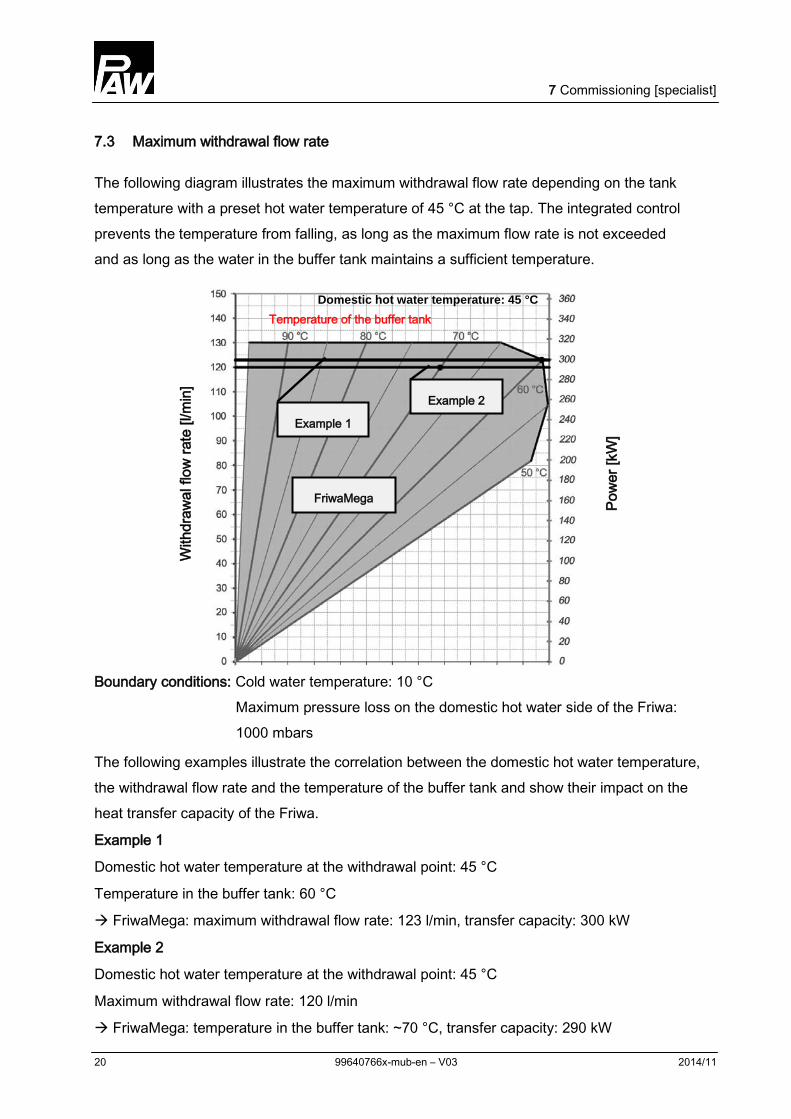
7.3 Maximum withdrawal flow rate
The following diagram illustrates the maximum withdrawal flow rate depending on the tank temperature with a preset hot water temperature of 45 °C at the tap. The integrated control prevents the temperature from falling, as long as the maximum flow rate is not exceeded and as long as the water in the buffer tank maintains a sufficient temperature.
With
draw
al fl
ow ra
te [l
/min
]
Pow
er [k
W]
Boundary conditions: Cold water temperature: 10 °C Maximum pressure loss on the domestic hot water side of the Friwa: 1000 mbars
The following examples illustrate the correlation between the domestic hot water temperature, the withdrawal flow rate and the temperature of the buffer tank and show their impact on the heat transfer capacity of the Friwa.
Example 1
Domestic hot water temperature at the withdrawal point: 45 °C
Temperature in the buffer tank: 60 °C
FriwaMega: maximum withdrawal flow rate: 123 l/min, transfer capacity: 300 kW
Example 2
Domestic hot water temperature at the withdrawal point: 45 °C
Maximum withdrawal flow rate: 120 l/min
FriwaMega: temperature in the buffer tank: ~70 °C, transfer capacity: 290 kW
Domestic hot water temperature: 45 °C
Example 1
Temperature of the buffer tank
FriwaMega
Example 2
7 Commissioning [specialist]
2014/11 99640766x-mub-en – V03 21
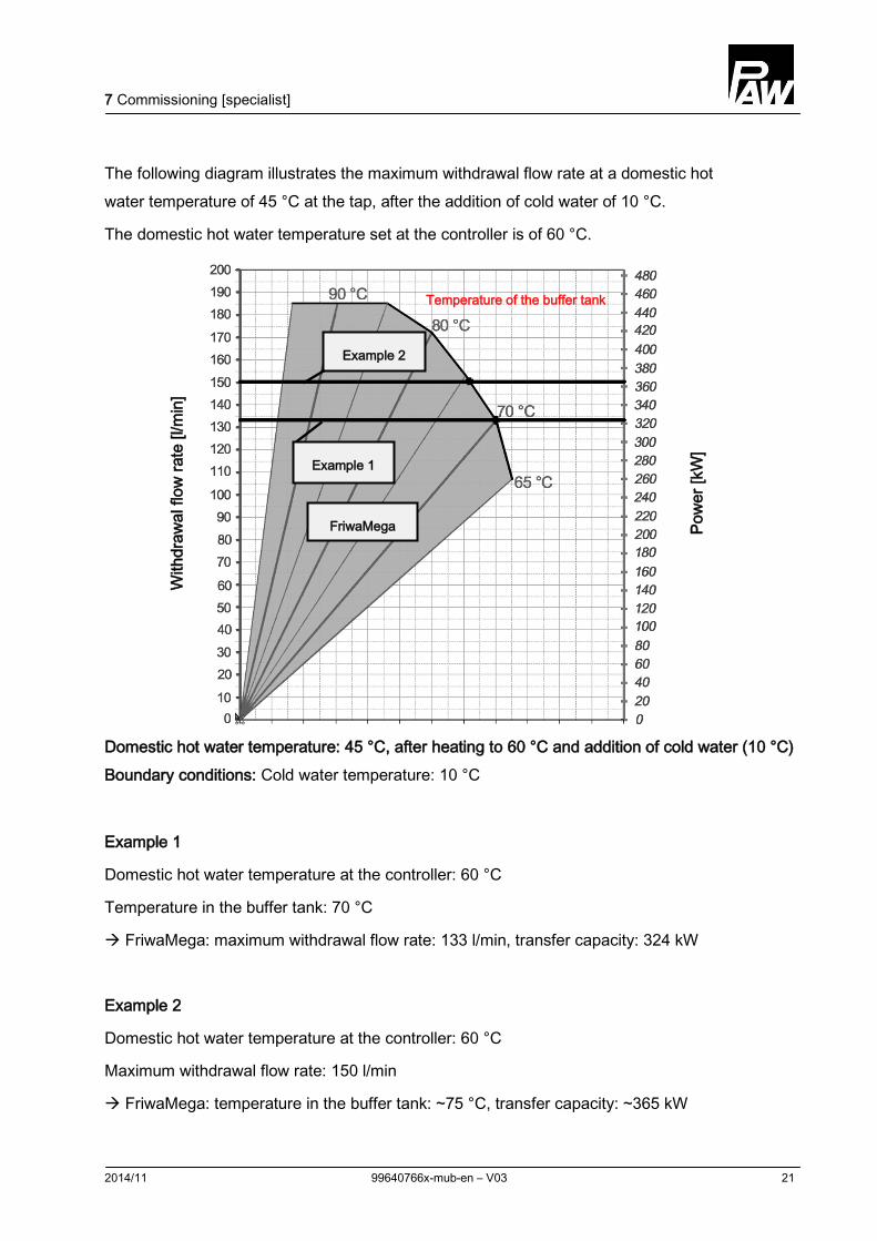
The following diagram illustrates the maximum withdrawal flow rate at a domestic hot water temperature of 45 °C at the tap, after the addition of cold water of 10 °C.
The domestic hot water temperature set at the controller is of 60 °C.
With
draw
al fl
ow ra
te [l
/min
]
Pow
er [k
W]
Domestic hot water temperature: 45 °C, after heating to 60 °C and addition of cold water (10 °C) Boundary conditions: Cold water temperature: 10 °C
Example 1
Domestic hot water temperature at the controller: 60 °C
Temperature in the buffer tank: 70 °C
FriwaMega: maximum withdrawal flow rate: 133 l/min, transfer capacity: 324 kW
Example 2
Domestic hot water temperature at the controller: 60 °C
Maximum withdrawal flow rate: 150 l/min
FriwaMega: temperature in the buffer tank: ~75 °C, transfer capacity: ~365 kW
Temperature of the buffer tank
Example 2
Example 1
FriwaMega
7 Commissioning [specialist]
22 99640766x-mub-en – V03 2014/11
7.4 Setting the temperature
Set the desired (maximum) domestic hot water temperature at the controller under "Para" (see controller instructions, page 24).
WARNING Danger of scalding due to hot water!
The maximum domestic hot water temperature must not exceed 60 °C in order to avoid scalding at the tap.
Primary circuit
The required temperature on the primary side in the buffer tank depends on the desired domestic hot water temperature and on the required tap quantity. The temperature in the buffer tank must be at least 5 K above the desired domestic hot water temperature.
Secondary side
The possible withdrawal flow rate [l/min] at the tap depends on the domestic hot water temperature set at the controller and on the temperature available in the buffer tank.
The maximum domestic hot water flow rate through the module FriwaMega is of 130 l/min.
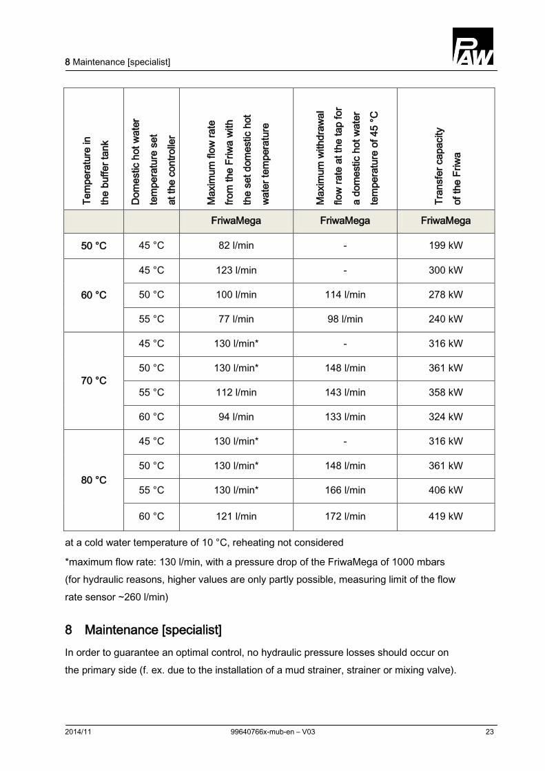
The following table illustrates the correlation between the storage tank temperature and the maximum withdrawal flow rate at a water temperature of 45 °C at the tap (f. ex. single lever tap). If the domestic hot water temperature set at the controller is above 45 °C, the withdrawal flow rate consists of a mixture of hot and cold water.
The indicated heat transfer capacity is necessary to heat up the water to be withdrawn [l/min] from 10 °C to 45 °C.
8 Maintenance [specialist]
2014/11 99640766x-mub-en – V03 23
Te
mpe
ratu
re in
the
buffe
r tan
k
Dom
estic
hot
wat
er
tem
pera
ture
set
at th
e co
ntro
ller
Max
imum
flow
rate
from
the
Friw
a w
ith
the
set d
omes
tic h
ot
wat
er te
mpe
ratu
re
Max
imum
with
draw
al
flow
rate
at t
he ta
p fo
r
a do
mes
tic h
ot w
ater
tem
pera
ture
of 4
5 °C
Tran
sfer
cap
acity
of th
e Fr
iwa
FriwaMega FriwaMega FriwaMega
50 °C 45 °C 82 l/min - 199 kW
60 °C
45 °C 123 l/min - 300 kW
50 °C 100 l/min 114 l/min 278 kW
55 °C 77 l/min 98 l/min 240 kW
70 °C
45 °C 130 l/min* - 316 kW
50 °C 130 l/min* 148 l/min 361 kW
55 °C 112 l/min 143 l/min 358 kW
60 °C 94 l/min 133 l/min 324 kW
80 °C
45 °C 130 l/min* - 316 kW
50 °C 130 l/min* 148 l/min 361 kW
55 °C 130 l/min* 166 l/min 406 kW
60 °C 121 l/min 172 l/min 419 kW
at a cold water temperature of 10 °C, reheating not considered
*maximum flow rate: 130 l/min, with a pressure drop of the FriwaMega of 1000 mbars (for hydraulic reasons, higher values are only partly possible, measuring limit of the flow rate sensor ~260 l/min)
8 Maintenance [specialist] In order to guarantee an optimal control, no hydraulic pressure losses should occur on the primary side (f. ex. due to the installation of a mud strainer, strainer or mixing valve).
9 Spare parts [specialist]
24 99640766x-mub-en – V03 2014/11
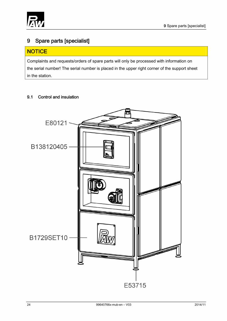
9 Spare parts [specialist]
NOTICE Complaints and requests/orders of spare parts will only be processed with information on the serial number! The serial number is placed in the upper right corner of the support sheet in the station.
9.1 Control and insulation
9 Spare parts [specialist]
2014/11 99640766x-mub-en – V03 25
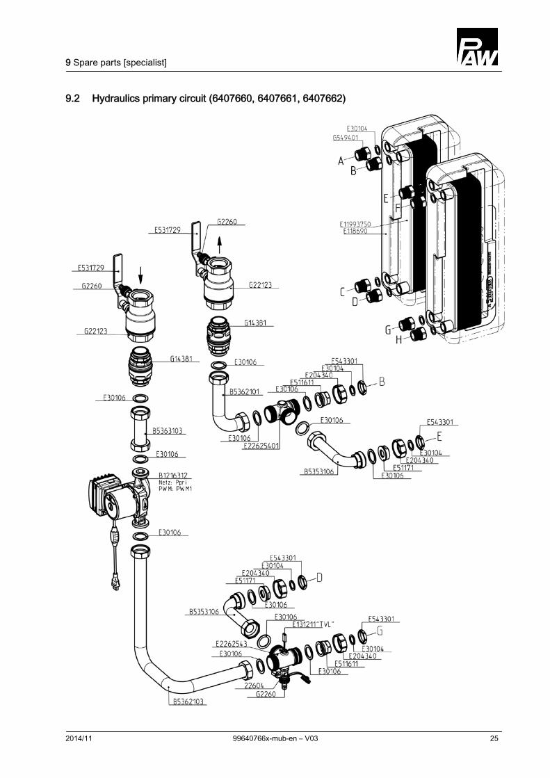
9.2 Hydraulics primary circuit (6407660, 6407661, 6407662)
9 Spare parts [specialist]
26 99640766x-mub-en – V03 2014/11
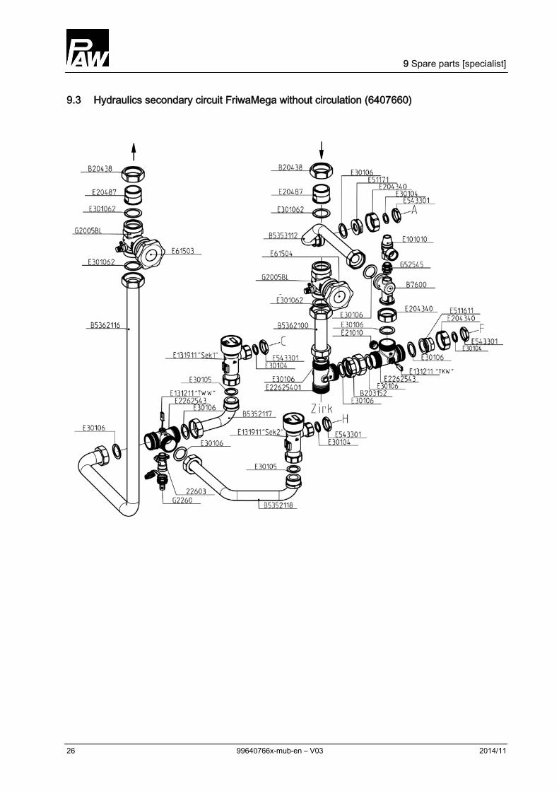
9.3 Hydraulics secondary circuit FriwaMega without circulation (6407660)
9 Spare parts [specialist]
2014/11 99640766x-mub-en – V03 27
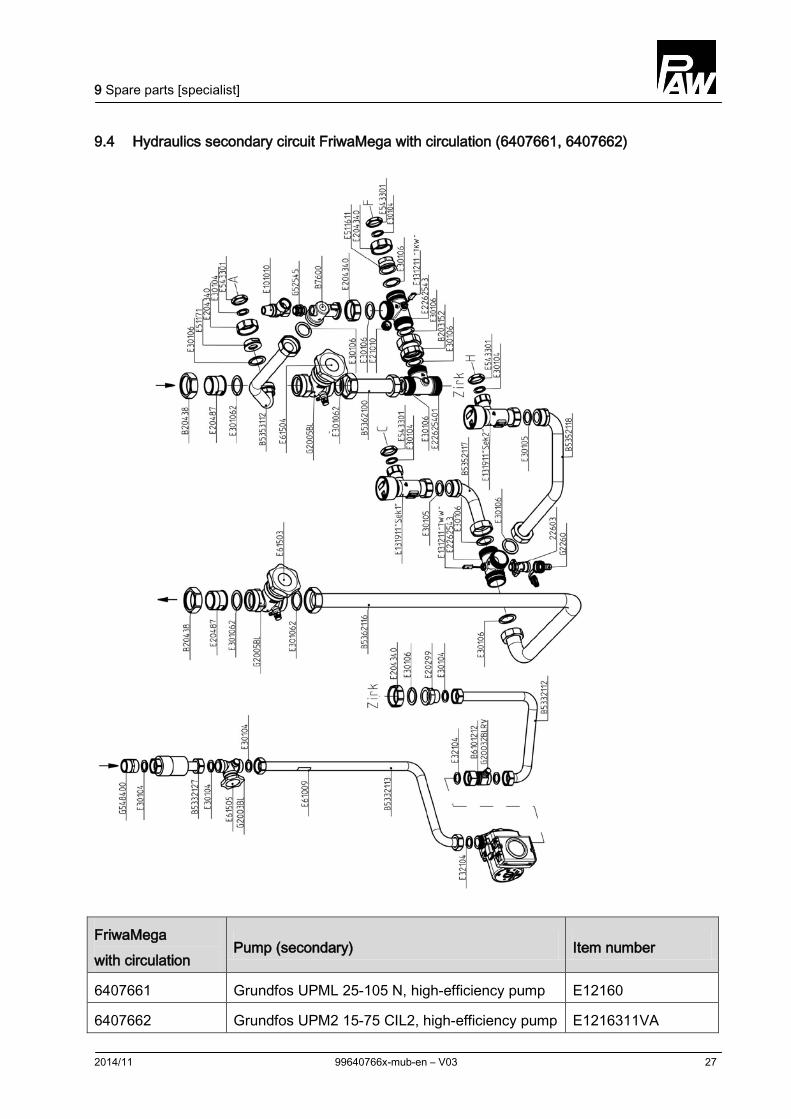
9.4 Hydraulics secondary circuit FriwaMega with circulation (6407661, 6407662)
FriwaMega with circulation
Pump (secondary) Item number
6407661 Grundfos UPML 25-105 N, high-efficiency pump E12160
6407662 Grundfos UPM2 15-75 CIL2, high-efficiency pump E1216311VA
10 Technical data
28 99640766x-mub-en – V03 2014/11
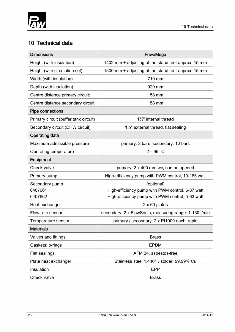
10 Technical data
Dimensions FriwaMega
Height (with insulation) 1402 mm + adjusting of the stand feet approx. 15 mm
Height (with circulation set) 1500 mm + adjusting of the stand feet approx. 15 mm
Width (with insulation) 710 mm
Depth (with insulation) 920 mm
Centre distance primary circuit: 158 mm
Centre distance secondary circuit 158 mm
Pipe connections
Primary circuit (buffer tank circuit) 1½" internal thread
Secondary circuit (DHW circuit) 1½" external thread, flat sealing
Operating data
Maximum admissible pressure primary: 3 bars, secondary: 10 bars
Operating temperature 2 – 95 °C
Equipment
Check valve primary: 2 x 400 mm wc, can be opened
Primary pump High-efficiency pump with PWM control, 10-185 watt
Secondary pump 6407661 6407662
(optional) High-efficiency pump with PWM control, 6-87 watt High-efficiency pump with PWM control, 5-63 watt
Heat exchanger 2 x 60 plates
Flow rate sensor secondary: 2 x FlowSonic, measuring range: 1-130 l/min
Temperature sensor primary / secondary: 2 x Pt1000 each, rapid
Materials
Valves and fittings Brass
Gaskets: o-rings EPDM
Flat sealings AFM 34, asbestos-free
Plate heat exchanger Stainless steel 1.4401 / solder: 99.99% Cu
Insulation EPP
Check valve Brass
10 Technical data
2014/11 99640766x-mub-en – V03 29
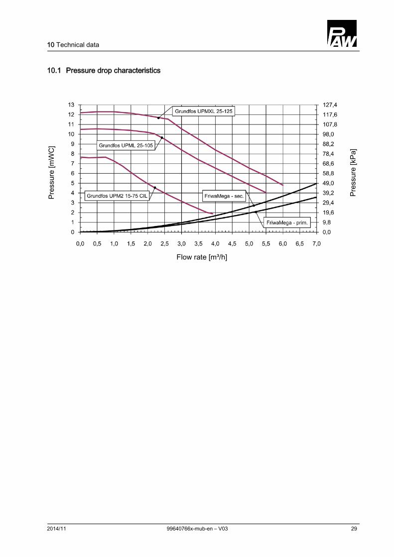
10.1 Pressure drop characteristics
Pres
sure
[mW
C]
Pres
sure
[kPa
]
Flow rate [m³/h]
11 Commissioning report
30 99640766x-mub-en – V03 2014/11
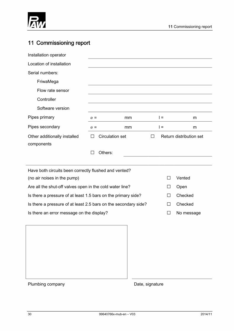
11 Commissioning report
Installation operator
Location of installation
Serial numbers:
FriwaMega
Flow rate sensor
Controller
Software version
Pipes primary ⌀ = mm l = m
Pipes secondary ⌀ = mm l = m
Other additionally installed components
Return distribution set ݩ Circulation set ݩ
:Others ݩ
Have both circuits been correctly flushed and vented? (no air noises in the pump) ݩ Vented
Are all the shut-off valves open in the cold water line? ݩ Open
Is there a pressure of at least 1.5 bars on the primary side? ݩ Checked
Is there a pressure of at least 2.5 bars on the secondary side? ݩ Checked
Is there an error message on the display? ݩ No message
Plumbing company Date, signature

11 Commissioning report
2014/11 99640766x-mub-en – V03 31

PAW GmbH & Co.KG
Böcklerstraße 11
D-31789 Hameln, Germany
www.paw.eu
Phone: +49 (0) 5151 9856 - 0
Fax: +49 (0) 5151 9856 - 98 99640766x-mub-en – V03 2014/11


![$7B +] Pump catalogue 1 SC-inline... · These bronze pumps are mainly used for the circulation of domestic hot water. They can also be used in standard circulation systems,](https://img.pdfslide.us/doc/110x75/5b02e9a67f8b9ab9598e856c/7b-pump-catalogue-1-sc-inlinethese-bronze-pumps-are-mainly-used-for-the-circulation.jpg)