Embed Size (px)
Citation preview
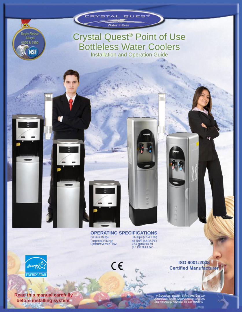
(All drawings, pictures, colors and sizes are approximate for illustrative purposes only and may not exactly resemble the end product.)
Read this manual carefully before installing system.
ISO 9001:2008Certified Manufacturer
OPERATING SPECIFICATIONSPressure Range: 30-60 psi (2.1-4.1 bar)Temperature Range: 40-100ºF (4.4-37.7ºC)Optimum Service Flow: 0.50 gpm at 60 psi (1.1 lpm at 4.1 bar)
Crystal Quest® Point of Use Bottleless Water Coolers
Installation and Operation Guide
Do not lay the cooler on its side.The system must be in an upright position at all times. When carrying, do not lift the system by the faucets/•spouts.Thesystemneedstobeinstalledbyalicensedplumberinanystateorcountry;however,thefollowingstatesspecificallyrequirealicensed•plumber to install the system OR allow a state-registered installer or contractor: AR, CA, GA, KS, MA, MI, MN, OK, RI, SC, SD, TX, VT, and WI.Apressureregulator,suchasaslow-flowregulator,mustbeinstalledinfrontoftheunit’swaterinletifthewaterpressure(includingany•possible pressure spikes) could exceed 60 psig. Failure to comply will void the warranty. Crystal Quest® accepts no liability for damage caused by excessive water pressure or improper installation.Installation must be made within a protected area covered from the elements and freezing. The unit must be protected from rain, dust, •flooding,snow,freezing,anddirectsunlight(thesystem’sdirectexposuretosunlightmaycausealgaegrowthinthetankreservoir).Failureto comply will void the warranty.Use only ¼” OD tubing to connect the cold water supply to the system.•Checkalltheconnections(i.e.,waterhose/tubing,connectors/fittings)toensureproperconnectionandavoidleaks.•Checkplumbinginletandoutlettoensuretheproperflowofwaterthroughthesystem.•Plug the system into a 110 volt grounded outlet which contains a fuse or circuit breaker of 20 amps.•Locate the system near a cold water supply line. Do not set the system farther than 15 ft. from the cold water line. Use copper tubing to •avoid water line puncture and rodent bites. Failure to do so may cause major property damage. Crystal Quest® accepts no liability for damage.Install the system in a well-ventilated area where the temperature is consistently above 60ºF.•System must have a 2” clearance on all sides to ensure proper ventilation.•Install the auto shut-off valve to control and reduce the cold water supply line pressure to 25 psi and maintain at 25 psi to avoid bursting.•Hotwatertankmustbefilledwithwaterbeforetheheatingon/offswitchisturnedon.•Do not use the system on cold water supply line with less than 20 psi.•Donotmovethecooleriffilledwithwater.•
Important Information .........................................................................................................................................................................2SystemSpecifications(Turbo/Sharp) ..................................................................................................................................................3SystemSpecifications(Elegant/Hybrid) ..............................................................................................................................................4 Installation Instructions ................................... ....................................................................................................................................5Circuit and Installation Diagrams ........................................................................................................................................................6Install Water Cooler System to Water Supply ......................................................................................................................................7Service Information and Guidelines .....................................................................................................................................................8Replacement Cartridges ......................................................................................................................................................................9Troubleshooting Guide (Water Problems) ...........................................................................................................................................10Troubleshooting Guide (Unit Problems) ..............................................................................................................................................11Access to Parts Inside the System ......................................................................................................................................................12Water Cooler Heating Reservoir Replacement Guide .........................................................................................................................13Water Coolers (Optional Cartridges & Accessories) ............................................................................................................................14System Warranty .................................................................................................................................................................................15Ordering Replacement Cartridges .......................................................................................................................................................16
Important Information
Table of Contents
2
(Please note all drawings, pictures, colors, and sizes are approximate for illustrative purposes only and may
not exactly resemble the end product.)
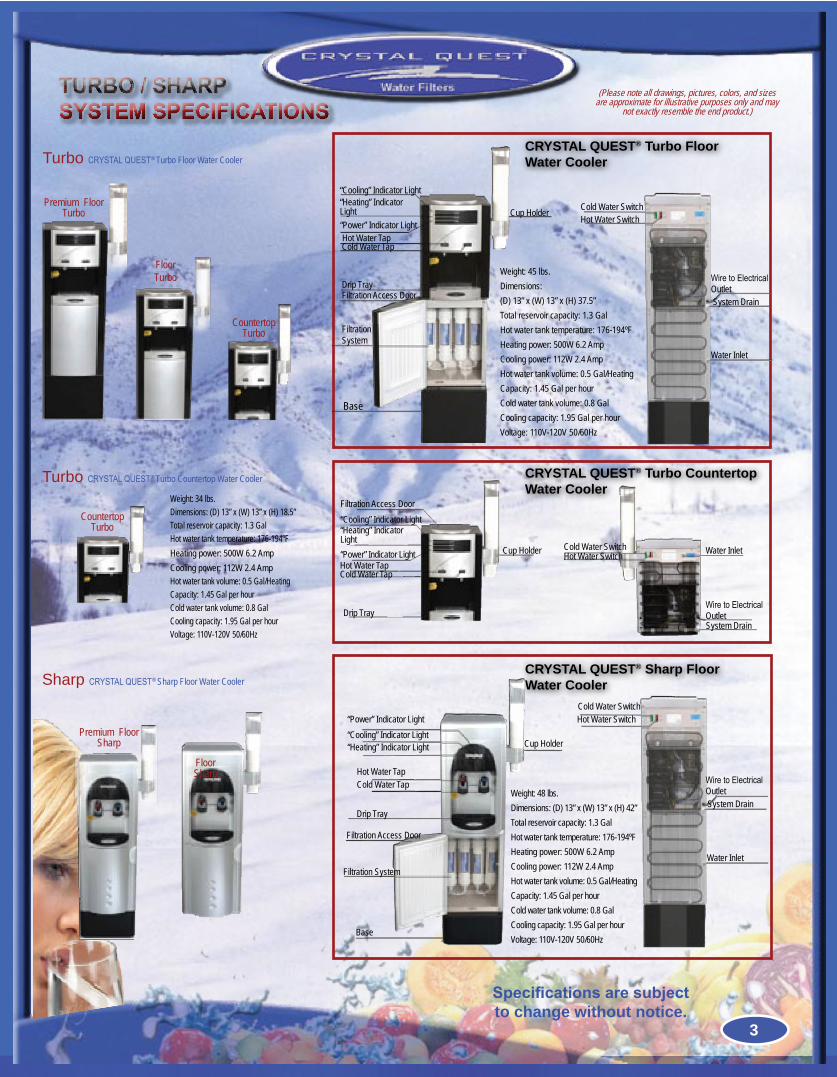
Turbo CRYSTALQUEST® Turbo Floor Water Cooler
Premium FloorTurbo
Floor Turbo
CountertopTurbo
TURBO / SHARPSYSTEM SPECIFICATIONS
Weight: 45 lbs.Dimensions: (D) 13” x (W) 13” x (H) 37.5”Total reservoir capacity: 1.3 GalHot water tank temperature: 176-194ºFHeating power: 500W 6.2 AmpCooling power: 112W 2.4 AmpHot water tank volume: 0.5 Gal/HeatingCapacity: 1.45 Gal per hourCold water tank volume: 0.8 GalCooling capacity: 1.95 Gal per hourVoltage: 110V-120V 50/60Hz
CRYSTAL QUEST® Turbo Floor Water Cooler
“Cooling” Indicator Light“Heating” Indicator Light
Hot Water TapCold Water Tap
“Power” Indicator Light
Drip TrayFiltration Access Door
Filtration System
Base
Cup Holder
WiretoElectricalOutlet
Cold Water SwitchHot Water Switch
System Drain
Water Inlet
Specifications are subject to change without notice.
Sharp CRYSTALQUEST® Sharp Floor Water CoolerCRYSTAL QUEST® Sharp Floor Water Cooler
Premium FloorSharp
Floor Sharp
“Cooling” Indicator Light“Heating” Indicator Light
Hot Water TapCold Water Tap
“Power” Indicator Light
Drip Tray
Filtration Access Door
Filtration System
Base
Cup Holder
WiretoElectricalOutlet
Cold Water SwitchHot Water Switch
System Drain
Water Inlet
Weight: 48 lbs.Dimensions: (D) 13” x (W) 13” x (H) 42”Total reservoir capacity: 1.3 GalHot water tank temperature: 176-194ºFHeating power: 500W 6.2 AmpCooling power: 112W 2.4 AmpHot water tank volume: 0.5 Gal/HeatingCapacity: 1.45 Gal per hourCold water tank volume: 0.8 GalCooling capacity: 1.95 Gal per hourVoltage: 110V-120V 50/60Hz
3
Weight: 34 lbs.Dimensions: (D) 13” x (W) 13” x (H) 18.5”Total reservoir capacity: 1.3 GalHot water tank temperature: 176-194ºFHeating power: 500W 6.2 AmpCooling power: 112W 2.4 AmpHot water tank volume: 0.5 Gal/HeatingCapacity: 1.45 Gal per hourCold water tank volume: 0.8 GalCooling capacity: 1.95 Gal per hourVoltage: 110V-120V 50/60Hz
Turbo CRYSTALQUEST® Turbo Countertop Water Cooler
CountertopTurbo
“Cooling” Indicator Light“Heating” IndicatorLight
Hot Water TapCold Water Tap
“Power” Indicator Light
Drip Tray
Filtration Access Door
Cup Holder
WiretoElectricalOutlet
Cold Water SwitchHot Water Switch
System Drain
Water Inlet
CRYSTAL QUEST® Turbo CountertopWater Cooler
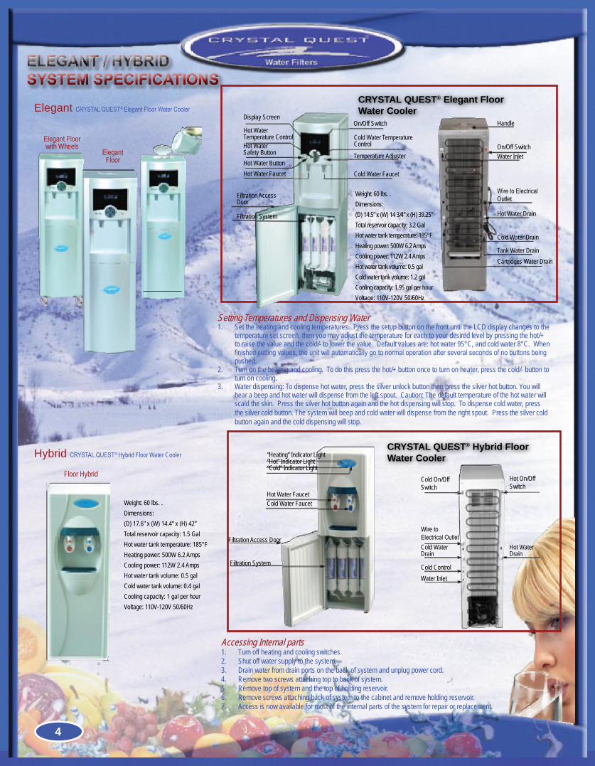
Elegant CRYSTALQUEST®ElegantFloorWaterCooler
Hybrid CRYSTALQUEST® Hybrid Floor Water Cooler
Floor Hybrid
ELEGANT / HYBRIDSYSTEM SPECIFICATIONS
ElegantFloorwith Wheels
ElegantFloor
Weight: 60 lbs. . Dimensions: (D) 17.6” x (W) 14.4” x (H) 42” Total reservoir capacity: 1.5 GalHot water tank temperature: 185°F Heating power: 500W 6.2 AmpsCooling power: 112W 2.4 AmpsHot water tank volume: 0.5 galCold water tank volume: 0.4 gal Cooling capacity: 1 gal per hourVoltage: 110V-120V 50/60Hz
CRYSTAL QUEST® Hybrid Floor Water Cooler
Setting Temperatures and Dispensing WaterSet the heating and cooling temperatures. Press the setup button on the front until the LCD display changes to the 1. temperature set screen, then you may adjust the temperature for each to your desired level by pressing the hot/+ to raise the value and the cold/- to lower the value. Default values are: hot water 95°C, and cold water 8°C. When finishedsettingvalues,theunitwillautomaticallygotonormaloperationafterseveralsecondsofnobuttonsbeingpushed.Turn on the heating and cooling. To do this press the hot/+ button once to turn on heater, press the cold/- button to 2. turn on cooling.Water dispensing: To dispense hot water, press the silver unlock button then press the silver hot button. You will 3. hear a beep and hot water will dispense from the left spout. Caution: The default temperature of the hot water will scald the skin. Press the silver hot button again and the hot dispensing will stop. To dispense cold water, press the silver cold button. The system will beep and cold water will dispense from the right spout. Press the silver cold button again and the cold dispensing will stop.
Accessing Internal partsTurn off heating and cooling switches.1. Shut off water supply to the system.2. Drain water from drain ports on the back of system and unplug power cord.3. Remove two screws attaching top to back of system.4. Remove top of system and the top of holding reservoir.5. Remove screws attaching back of system to the cabinet and remove holding reservoir.6. Access is now available for most of the internal parts of the system for repair or replacement.7.
“Cold” Indicator Light
“Heating” Indicator Light“Hot” Indicator Light
Hot Water FaucetCold Water Faucet
Filtration Access Door
Filtration System
Water InletCold Control
Cold Water Drain
Hot Water Drain
Wire to ElectricalOutlet
Cold On/Off Switch
Hot On/Off Switch
On/Off Switch
Handle
Water Inlet
Hot Water Drain
Cold Water Drain
Tank Water DrainCartridges Water Drain
WiretoElectricalOutlet
Display ScreenOn/Off Switch
Temperature Adjuster
Cold Water Faucet
Cold Water TemperatureControlHot Water
Safety Button
Filtration AccessDoor
Hot Water ButtonHot Water Faucet
Filtration System
Hot Water Temperature Control
CRYSTAL QUEST® Elegant Floor Water Cooler
Weight: 60 lbs. . Dimensions: (D) 14.5” x (W) 14 3/4” x (H) 39.25” Total reservoir capacity: 3.2 GalHot water tank temperature: 185°F Heating power: 500W 6.2 AmpsCooling power: 112W 2.4 AmpsHot water tank volume: 0.5 galCold water tank volume: 1.2 gal Cooling capacity: 1.95 gal per hourVoltage: 110V-120V 50/60Hz
4
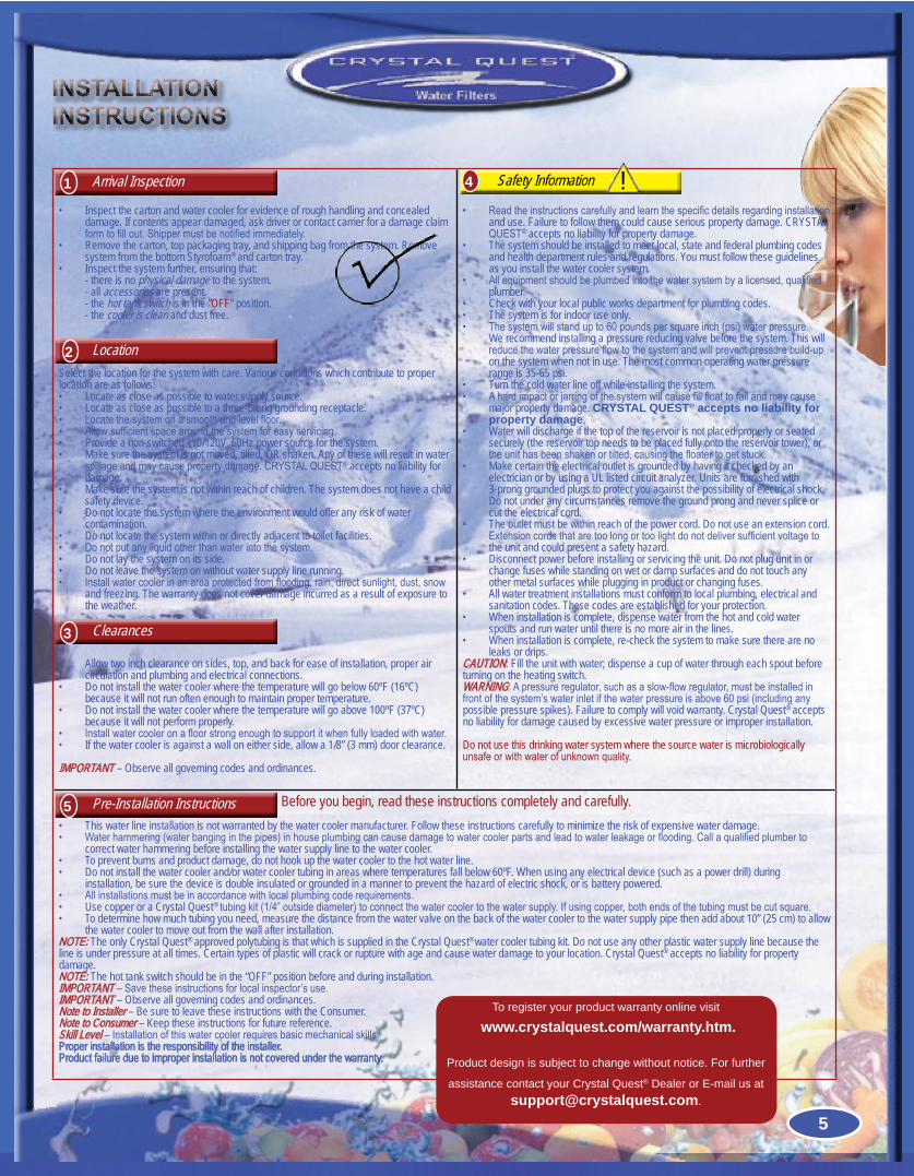
Inspect the carton and water cooler for evidence of rough handling and concealed •damage. If contents appear damaged, ask driver or contact carrier for a damage claim formtofillout.Shippermustbenotifiedimmediately.Remove the carton, top packaging tray, and shipping bag from the system. Remove •system from the bottom Styrofoam® and carton tray. Inspect the system further, ensuring that:•- there is no physical damage to the system.- all accessories are present.- the hot tank switch is in the “OFF” position.- the cooler is clean and dust free.
Select the location for the system with care. Various conditions which contribute to proper location are as follows:
Locate as close as possible to water supply source.•Locate as close as possible to a three-prong grounding receptacle.•Locatethesystemonasmoothandlevelfloor.•Allowsufficientspacearoundthesystemforeasyservicing.•Provide a non-switched 110/120V, 60Hz power source for the system.•Make sure the system is not moved, tilted, OR shaken. Any of these will result in water •spillageandmaycausepropertydamage.CRYSTALQUEST® accepts no liability for damage.Make sure the system is not within reach of children. The system does not have a child •safety device.Do not locate the system where the environment would offer any risk of water •contamination.Do not locate the system within or directly adjacent to toilet facilities.•Donotputanyliquidotherthanwaterintothesystem.•Do not lay the system on its side.•Do not leave the system on without water supply line running.•Installwatercoolerinanareaprotectedfromflooding,rain,directsunlight,dust,snow•and freezing. The warranty does not cover damage incurred as a result of exposure to the weather.
Allow two inch clearance on sides, top, and back for ease of installation, proper air •circulation and plumbing and electrical connections.Do not install the water cooler where the temperature will go below 60ºF (16ºC) •because it will not run often enough to maintain proper temperature.Do not install the water cooler where the temperature will go above 100ºF (37ºC) •because it will not perform properly.Installwatercooleronafloorstrongenoughtosupportitwhenfullyloadedwithwater.•If the water cooler is against a wall on either side, allow a 1/8” (3 mm) door clearance.•
IMPORTANT – Observe all governing codes and ordinances.
Readtheinstructionscarefullyandlearnthespecificdetailsregardinginstallation•and use. Failure to follow them could cause serious property damage. CRYSTAL QUEST® accepts no liability for property damage.The system should be installed to meet local, state and federal plumbing codes •and health department rules and regulations. You must follow these guidelines as you install the water cooler system.Allequipmentshouldbeplumbedintothewatersystembyalicensed,qualified•plumber.Check with your local public works department for plumbing codes.•The system is for indoor use only.•Thesystemwillstandupto60poundspersquareinch(psi)waterpressure.•We recommend installing a pressure reducing valve before the system. This will reducethewaterpressureflowtothesystemandwillpreventpressurebuild-upon the system when not in use. The most common operating water pressure range is 35-65 psi.Turn the cold water line off while installing the system.•Ahardimpactorjarringofthesystemwillcausefillfloattofailandmaycause•major property damage. CRYSTAL QUEST® accepts no liability for property damage.Water will discharge if the top of the reservoir is not placed properly or seated •securely (the reservoir top needs to be placed fully onto the reservoir tower), or theunithasbeenshakenortilted,causingthefloatertogetstuck.Make certain the electrical outlet is grounded by having it checked by an •electrician or by using a UL listed circuit analyzer. Units are furnished with 3-prong grounded plugs to protect you against the possibility of electrical shock. Do not under any circumstances remove the ground prong and never splice or cut the electrical cord.The outlet must be within reach of the power cord. Do not use an extension cord. •Extensioncordsthataretoolongortoolightdonotdeliversufficientvoltagetothe unit and could present a safety hazard.Disconnect power before installing or servicing the unit. Do not plug unit in or •change fuses while standing on wet or damp surfaces and do not touch any other metal surfaces while plugging in product or changing fuses.All water treatment installations must conform to local plumbing, electrical and •sanitation codes. These codes are established for your protection.When installation is complete, dispense water from the hot and cold water •spouts and run water until there is no more air in the lines.When installation is complete, re-check the system to make sure there are no •leaks or drips.
CAUTION: Fill the unit with water; dispense a cup of water through each spout before turning on the heating switch.WARNING:Apressureregulator,suchasaslow-flowregulator,mustbeinstalledinfrontofthesystem’swaterinletifthewaterpressureisabove60psi(includinganypossible pressure spikes). Failure to comply will void warranty. Crystal Quest® accepts no liability for damage caused by excessive water pressure or improper installation.
Do not use this drinking water system where the source water is microbiologically unsafeorwithwaterofunknownquality.
Before you begin, read these instructions completely and carefully.This water line installation is not warranted by the water cooler manufacturer. Follow these instructions carefully to minimize the risk of expensive water damage.•Waterhammering(waterbanginginthepipes)inhouseplumbingcancausedamagetowatercoolerpartsandleadtowaterleakageorflooding.Callaqualifiedplumberto•correct water hammering before installing the water supply line to the water cooler.To prevent burns and product damage, do not hook up the water cooler to the hot water line.•Do not install the water cooler and/or water cooler tubing in areas where temperatures fall below 60ºF. When using any electrical device (such as a power drill) during •installation, be sure the device is double insulated or grounded in a manner to prevent the hazard of electric shock, or is battery powered.Allinstallationsmustbeinaccordancewithlocalplumbingcoderequirements.•Use copper or a Crystal Quest• ®tubingkit(1/4”outsidediameter)toconnectthewatercoolertothewatersupply.Ifusingcopper,bothendsofthetubingmustbecutsquare.To determine how much tubing you need, measure the distance from the water valve on the back of the water cooler to the water supply pipe then add about 10” (25 cm) to allow •the water cooler to move out from the wall after installation.
NOTE: The only Crystal Quest® approved polytubing is that which is supplied in the Crystal Quest® water cooler tubing kit. Do not use any other plastic water supply line because the line is under pressure at all times. Certain types of plastic will crack or rupture with age and cause water damage to your location. Crystal Quest® accepts no liability for property damage.NOTE: The hot tank switch should be in the “OFF” position before and during installation.IMPORTANT–Savetheseinstructionsforlocalinspector’suse.IMPORTANT – Observe all governing codes and ordinances.Note to Installer – Be sure to leave these instructions with the Consumer.Note to Consumer – Keep these instructions for future reference.Skill Level –Installationofthiswatercoolerrequiresbasicmechanicalskills.Proper installation is the responsibility of the installer.Product failure due to improper installation is not covered under the warranty.
INSTALLATIONINSTRUCTIONS
To register your product warranty online visit
www.crystalquest.com/warranty.htm.
Product design is subject to change without notice. For further
assistance contact your Crystal Quest® Dealer or E-mail us at [email protected].
Arrival Inspection1
Location2
Clearances3
Pre-Installation Instructions5
Safety Information4 !
5
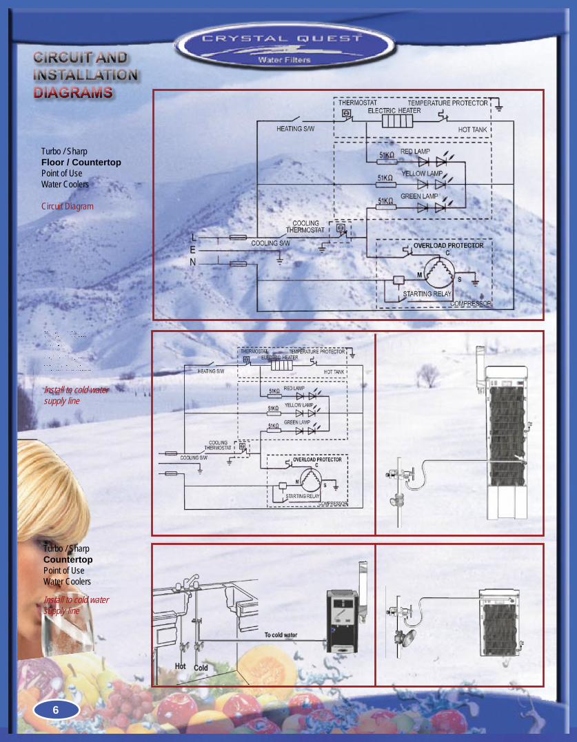
Turbo / Sharp Floor Point of Use Water Coolers
Install to cold water supply line
Turbo / Sharp Floor / CountertopPoint of Use Water Coolers
Circuit Diagram
Turbo / Sharp Countertop Point of Use Water Coolers
Install to cold water supply line
CIRCUIT AND INSTALLATIONDIAGRAMS
6
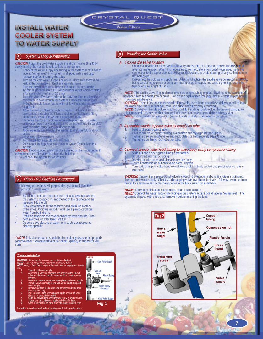
A. Choose the valve location.Choose a location for the valve that is easily accessible. It is best to connect into the side of •a vertical water pipe. When it is necessary to connect into a horizontal water pipe, make the connection to the top or side, rather than at the bottom, to avoid drawing off any sediment from the water pipe.Disconnect the cold water supply line. Attach and tighten the saddle valve connector assembly, •beingcarefulnottopinchorcrimpanytubingorwatersupplylinewhiletightening.UseTeflon®
tapetoensureatightfit(Fig2).
NOTE: The saddle valve (Fig 2) clamps onto soft or hard tubing or pipe. It will make its own hole in copper tubing but not in iron or brass. For brass or galvanized iron pipe, drill a ¼” hole in pipe before mounting saddle valve. CAUTION: There is risk of electric shock. If possible, use a hand or cordless drill when drilling into the water pipe. Be sure that drill, cord, and outlet are all properly grounded.NOTE: Do not turn handle before installing or while installing saddle valve. To prevent damage to piercing needle, make sure that piercing lance does not project beyond the rubber gasket.NOTE:Leavehandleinthisposition(valveclosed)untilfilterinstallationiscomplete.
B. Assemble saddle-tapping valve assembly on tube.Hold back plate against tube.1. Hold saddle valve against tubing in a position directly opposite back plate.2. Tighten screw so saddle valve and back plate are held securely against tube.3. Tightenscrewfirmly.Donotcrushtube.4.
C.Connectsourcewaterfeedtubingtovalvebodyusingcompressionfitting.Slide nut and sleeve onto tubing (in that order).1. Install insert into plastic tubing.2. Install tube with insert and sleeve into valve body.3. Thread compression nut onto valve body. Tighten.4. Turnsaddle-tappingvalvehandleclockwiseuntilitisfirmlyseatedandpiercinglanceisfully5. extended.
CAUTION: Supply line is pierced and valve is closed. Do not open valve until system is activated. Turn on cold water supply. Check saddle-tapping valve installation for leaks. Allow water to run from faucet for a few minutes to clear any debris in the line caused by installation.
NOTE:Ifflowfromsinkfaucetisreduced,cleanfaucetaerator.NOTE: Connect the water supply line tubing to the system access board labeled “water inlet.” The system is shipped with a red cap; remove it before inserting the tube.
INSTALL WATERCOOLER SYSTEM TO WATER SUPPLY
CAUTION: Adjust the cold water supply line at the T-Valve (Fig 1) by slowlyturningthehandletoreduceflowtothesystem.
Connect the water supply line tubing to the system access board •labeled “water inlet”. The system is shipped with a red cap; remove it before inserting the tube.Turn on the cold water supply line again. Make sure there is no •leak at the connections. Recheck for water leaks.Plug the power cord into a receptacle outlet. Make sure the •system is plugged into a 110 volt grounded outlet which contains a fuse or circuit breaker of 20 amps.Turn the shut-off valve handle to the “ON” position to allow the •coldwatertoflowthroughthesystem.Checkthatwaterflowsthroughthecoldfaucet;waterwillnotflowifelectricalisnotplugged in.Allowthewatertoflowthroughthesystem.Checkall •connectionsincludingthefiltersandallothertubingandfittingconnections inside the system for possible leaks.Dispense the hot and cold water faucet/spouts and run water •untilwaterflowsfreelyandthereisnoairinthelines.Becareful:water from hot faucet can scald your hands.Allowwatertoflowthroughthesystemtorefillthecoldandhot•tanks.Flushfilters/membrane.*•Turn on the hot and cold tank switches. •Donotusethefirstthreereservoirsofwater.Theseflushthe•system.
CAUTION: Flood stopper valve must be installed on the water cooler if the water cooler is installed in a high rise building.
Recheck the system for water leaks.•
System Set-up & Preparation6
The following procedures will prepare the system to deliver the best possible drinking water.
Esurethatfiltersareinstalled,hotandcoldswitchesareoff,1. the system is plugged in, and the top of the cabinet and the reservoir lids are off.Allowwaterflowtofillthereservoiranddrainthesystem2. three times. Avoid water spills, and use a pan to catch the waterfrombothdrains.*Refillthereservoirandcovercabinetbyreplacinglids.Turn3. both switches on after tanks are full.Dispense two glasses of water from each faucet/spout to 4. clear trapped air.
Filters/ROFlushingProcedures*7
Installing the Saddle Valve8
T-Valve Installation
WARNING: Water supply pressure must not exceed 60 psi. NOTE:T-Valveisdesignedforinstallationonflexlinetubing. NOTE: Always check the local plumbing codes before tapping into a water line.
Turn off cold water supply.1. Assemble T-Valve by screwing and tightening the shut-off 2. valve into the water supply connector. Use thread tape on threads.Disconnect source water feed tubing from cold water supply.3. Install T-Valve assembly in line with water feed tubing and 4. water supply.Remove nut from feed end of shut-off valve and slide over 5. filtersupplytubing.Press end of tubing over exposed nipple on shut-off valve. 6. Ensureitiscompletelyseated.Slide nut down tubing and tighten securely to shut-off valve.7. Slowly turn on cold water supply and check for leaks.8. OpenT-Valveshut-offvalveslowlytosupplywatertofilter.9.
For further instructions on T-Valve assembly, see T-Valve product label.Fig 1
Fig 2
*NOTE: This drained water should be immediately disposed of properly (poured down a drain) to prevent accidental spilling, as this water will stain.
7
Turn off hot and cold switches, then turn off water supply.1. Disconnect the power supply from the cooler.2. Drain hot-cold water tank and water from the reservoir by opening the system drain.3. Drainwaterfromthereservoirandhottank(iffitted)throughthefaucets.4. Wash hands thoroughly.5. Put on disposable gloves.6. Wash the faucets and reservoir using mild cleaning agent. Parts MUST be completely 7. submerged in the solution. Rinse with clean water immediately.Reassemble the water cooler using the sanitized components.8. Sanitizehotandcoldtank(iffitted)andentirecoolerwithanewbatchofsanitizingsolution.9. Completelyfillthecoolerwithsanitizingsolutionandletstandfor5minutes.10. Drainsolutionthroughhotandcoldtankdrain(iffitted)orthroughfaucets.11. Rinse with clean water immediately.12. Reconnectthecoldsupplylinetocooler’sinlettube.13. Flush the reservoir at least three times to remove any traces of the sanitizing solution.14. Use chlorine test kit to identify the presence of any contaminants.15. If contamination still exists, repeat steps 13 and 14.16. Clean the outside of the cabinet and the drip tray, using a mild cleaning agent.17. Reconnect the power supply to the cooler.18.
CAUTION: FAILURETOTURNOFFHOTTANKCOULDCAUSEPHYSICALDAMAGETOTHISUNIT.
SERVICE INFORMATIONAND GUIDELINES
Fig 10
Fig 11
Fig 13
Fig 12
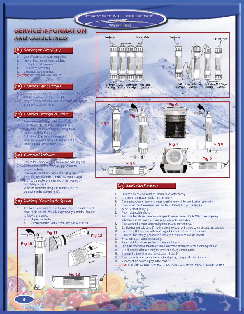
Shut off water at the water supply line.1. Turn off hot and cold water switches. 2. Unplug the cord from outlet.3. Drain tubing completely.4. Disconnecttubefromfilter.5.
CAUTION:HOTWATERWILLSCALD.
Servicing the Filter (Fig 3)9
Loosentheconnectorfittingcounterclockwise(Fig4).1. Pull the cartridge out of the main fold.2. WraptheconnectorfittingwithTeflon3. ® tape and connect it to a new cartridge (Fig 5).
Changing Filter Cartridges10
Remove two screws from the back (Fig 6).1. Pull the lid up to locate the cartridge (Fig 7).2. Loosentheconnectorfittingsbyturningthem3. counterclockwise (Fig 8).Pull the cartridge out of the main fold.4. WraptheconnectorfittingwithTeflon5. ® tape and connect it to a new cartridge (Fig 9).
Changing Cartridges in System11
Loosentheconnectorfittingcounterclockwise(Fig10).1. Remove the membrane housing cap by turning 2. counterclockwise.Remove the membrane with a pincer (Fig 11).3. Insert the membrane by carefully pushing the spigot 4. end into the socket at the far end of the housing until completely in (Fig 12).WraptheconnectorfittingwithTeflon5. ® tape and connect it to the tubing (Fig 13).
Changing Membranes12
The back static condenser on the rear of the unit must be kept 1. clean of dirt and lint. Visually inspect every 3 months. To clean it, follow these steps:a. Unplug the cooler.b. Clean condenser with a small, stiff, non-wire brush.
Sanitizing / Cleansing the System13
Sanitization Procedure14
Fig 5
Fig 3
Fig 4
Fig 7
Fig 6
Fig 9
Fig 8
Feedwater
SedimentCartridge
GACCartridge
UltrafiltrationCartridge
Multi StageCartridge
Filtered Water Feedwater
GACCartridge
Reverse OsmosisCartridge
UltrafiltrationCartridge
Multi StageCartridge
Filtered Water
8
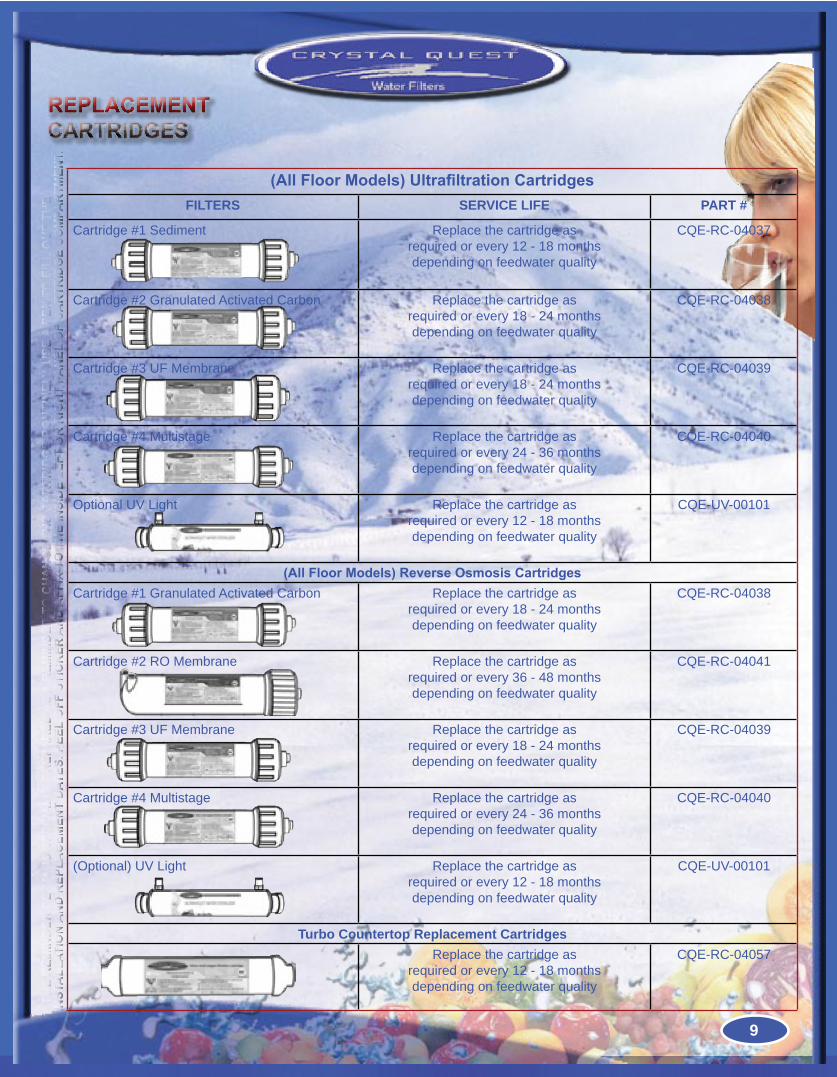
(All Floor Models) Ultrafiltration CartridgesFILTERS SERVICE LIFE PART #
Cartridge #1 Sediment Replace the cartridge as required or every 12 - 18 months depending on feedwater quality
CQE-RC-04037
Cartridge #2 Granulated Activated Carbon Replace the cartridge as required or every 18 - 24 months depending on feedwater quality
CQE-RC-04038
Cartridge #3 UF Membrane Replace the cartridge as required or every 18 - 24 months depending on feedwater quality
CQE-RC-04039
Cartridge #4 Multistage Replace the cartridge as required or every 24 - 36 months depending on feedwater quality
CQE-RC-04040
Optional UV Light Replace the cartridge as required or every 12 - 18 months depending on feedwater quality
CQE-UV-00101
(All Floor Models) Reverse Osmosis CartridgesCartridge #1 Granulated Activated Carbon Replace the cartridge as
required or every 18 - 24 months depending on feedwater quality
CQE-RC-04038
Cartridge #2 RO Membrane Replace the cartridge as required or every 36 - 48 months depending on feedwater quality
CQE-RC-04041
Cartridge #3 UF Membrane Replace the cartridge as required or every 18 - 24 months depending on feedwater quality
CQE-RC-04039
Cartridge #4 Multistage Replace the cartridge as required or every 24 - 36 months depending on feedwater quality
CQE-RC-04040
(Optional) UV Light Replace the cartridge as required or every 12 - 18 months depending on feedwater quality
CQE-UV-00101
Turbo Countertop Replacement CartridgesReplace the cartridge as
required or every 12 - 18 months depending on feedwater quality
CQE-RC-04057
REPLACEMENTCARTRIDGES
* Th
e R
emin
deR
dec
al
is s
pec
iall
y pR
epa
Red
as
a R
emin
deR
To
ch
an
ge
The
ca
RTR
idg
e R
ou
Tin
ely.
use
a p
en T
o f
ill
ou
T Th
e in
sTa
llaT
ion
an
d R
epla
cem
enT
daT
es. p
eel
off
sTi
ck
eR a
nd
aff
ix T
o T
he
insi
de
lefT
oR
Rig
hT
pan
el o
f c
aR
TRid
ge
co
mpa
RTm
enT.
9
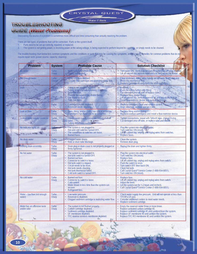
Discoveringthesourceofaproblemissometimesmoredifficultandtimeconsumingthanactuallyresolvingtheproblem.
There are two types of problems that call for correction: Parts or the system itself.Parts need to be set up correctly, repaired, or replaced.1. The system is not getting power, is receiving power at the wrong voltage, is being expected to perform beyond its capability, or simply needs to be cleaned.2.
The troubleshooting chart below lists common symptoms and the conditions or parts that may be causing the symptoms, and discusses remedies for common problems that do not requirerepairwork(powersource,capacity,cleaning).
Problem System Probable Cause Solution ChecklistNo water
TurboSharp
Water supply is turned OFF.•Floater has tripped.•
Turn water ON. Verify Crystal Quest® water shut-off valve is open.•Liftoffcabinettop,removereservoir’slid,andadjustthefloater.•
Not enough water TurboSharp
Water supply is blocked.•Cloggedfiltercartridgesarerestrictingwaterflow.•
Clear restriction, rotate valve handle on tap water feed valve and •checkthemechanicalfloat.Replace Cartridge #3 and check the other cartridges.•
Leak TurboSharp
Fitting is not properly installed.•Tubingisnotpushedcompletelyintofitting.•Defective tube.•Wornordamagedfittingand/orO-ring.•Thefloaterisstuck.•Tube has burst.•
Reinstall.•Pushthetubingfurtherontofitting.•Cut damaged area off tube or replace tube.•Replacefittingand/orO-ring.•Liftoffcabinettop,removereservoirlid,andadjustthefillfloat.•Installflow-restrictordeviceandreplacebursttube.•
Water looks murky Turbo Cartridge(s) is/are depleted.•Reservoir needs cleaning.•
Replace cartridges, clean and sanitize system.•Drainreservoir,sanitize,andletitrefill.•
Leakatfilter TurboSharp
Stem,fitting,and/orO-ringhasnickorscratches.•Cartridge(s) has/have cracks or scratches.•
Replacefittingand/orO-ring.•Replacecrackedcartridge(s)andinstallaflow-restrictordevice.•
Leak at water supply connector TurboSharp
Loosen water supply connector; loosen shut-off •valve.Tubing deformed.•
Tightenconnections,resealwithTeflon®tape,changeO-ring.•Cut damaged area off tube, or replace tube and sleeve.•
No indicator lights on TurboSharp
The system is not plugged in.•Hot and cold switches turned OFF.•The connectors to switches are loose.•Burned fuses.•
Plug the system into electrical outlet.•Turn switches ON (reset).•Lift off cabinet top, unplug, and replug wires from switches.•Replace fuses.•
No drain water TurboSharp
Clogged water drains.•Hole or drain tube blockage.•
Clean the system.•Remove drain plug.•
Leaking drain assembly TurboSharp
Drain plug or drain cover is not properly plugged or •firmlytightened.
Replugthedrainandtightenfirmly.•
No hot water TurboSharp
The system is not plugged in.•Hot tank switch is turned OFF.•Burned out fuse.•Connector to switch is loose.•Hot tank switch is tripped.•Circuit needs to be reset.•Hot tank needs cleaning.•Hot tank thermostat failed.•Cold tank switch is turned OFF.•
Plug the system into electrical outlet.•Turn switches ON (reset).•Replace fuse.•Lift off cabinet top, unplug and replug wires from switch.•Push the switch to reset.•Turn switch OFF then back ON.•Clean hot tank.•Call Crystal Quest• ® Service Center (1-800-934-0051).Turn switches ON (reset).•
No cold water TurboSharp
Burned out fuse.•Connector to switch is loose.•Cold control. •Water drawn in less time than the system can •recover.Refrigerant loss.•
Replace fuse.•Lift off cabinet top, unplug and replug wires from switch.•Adjust the level.•Let the system run for 1-2 hours and recheck.•Call Crystal Quest• ® Service Center (1-800-934-0051).
Water–lowflow(notenoughwater)
TurboSharp
Low water pressure.•Reservoir is depleted.•Cloggedsedimentcartridgeisrestrictingwaterflow.•
Check water supply line pressure. Unit will not operate at less than •173 kPa (25 psi).Consider additional coolers to meet water needs.•Replace sediment cartridge.•
Water has an offensive taste and/or odor
TurboSharp
Thesystemisnotflushedproperly.•Carbon cartridge depleted.•Sediment cartridge depleted.•UF membrane depleted.•TFC reverse osmosis membrane depleted.•
Emptythereservoirwaterthreeormoretimes.•Replace activated carbon cartridge #2.•Replace sediment cartridge #1 and sanitize/clean the system.•Replace UF membrane #3 and sanitize the system.•Replace TFC RO membrane #2 and sanitize the system.•
TROUBLESHOOTINGGUIDE (Water Problems)
10
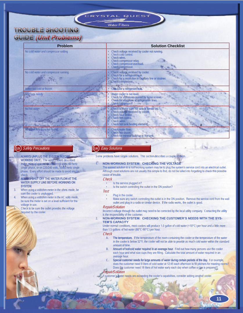
Problem Solution ChecklistNo cold water and compressor rattling Check voltage received by cooler not running.•
Check cold control.•Check wires.•Check compressor relay.•Check compressor overload.•Check compressor.•
No cold water and compressor running Check voltage received by cooler.•Check for a refrigerant leak.•Check for a restriction in capillary line or strainer.•Check compressor.•
Water too cold or frozen Check for a refrigerant leak.•Unit runs noisily Water cooler is not level.•
Check for vibrations caused by loose screws.•Check for vibrations at refrigeration lines.•Check compressor.•
No hot water Check to make sure hot tank is turned on.•Check voltage received by cooler.•Check heat limiter.•Check hot control.•Check wires.•Check hot tank heating element.•
Nowaterflowfromhotfaucet Checkwaterflow.•Check hot faucet.•Check for mineral build-up in hot tank.•
1. ALWAYSUNPLUGTHESYSTEMBEFOREWORKING ON IT. The water coolers described in this manual operate on either 110 volts, 60 hertz single phase, or on 220/240 volts, 50/60 hertz single phase.Everyeffortshouldbemadetoavoidelectricshock.
2. ALWAYSSHUTOFFTHEWATERFLOWATTHEWATERSUPPLYLINEBEFOREWORKINGONSYSTEM.
3. When using a volt/ohm meter in the ohms mode, be sure the cooler is unplugged.
4. When using a volt/ohm meter in the AC volts mode, besurethemeterissetonalevelsufficientforthevoltage in use.
5. Check to be sure the outlet provides the voltage requiredbythecooler.
TROUBLE SHOOTINGGUIDE (Unit Problems)
Some problems have simple solutions. This section describes a couple of them.
1. NON-WORKING SYSTEM: CHECKING THE VOLTAGETheeasiestsolutiontoanon-workingsystemmaybetoplugthesystem’sservicecordintoanelectricaloutlet.Althoughmostsolutionsarenotusuallythissimpletofind,donotbelulledintoforgettingtocheckthispossiblecause of trouble.Check
• Istheservicepluggedin?• IstheswitchcontrollingtheoutletintheONposition?
Test• Pluginthecooler.• MakesureanyswitchcontrollingtheoutletisintheONposition.Removetheservicecordfromthewall
outlet and plug in a radio or similar device. If the radio works, the outlet is good.Repair/SolutionIncorrect voltage through the outlet may need to be corrected by the local utility company. Contacting the utility is the responsibility of the customer.
2. NON-WORKING SYSTEM: CHECKING THE CUSTOMER’S NEEDS WITH THE SYS-TEM’S CAPACITYUnder normal conditions, most coolers will produce 1.0 gallon of cold water (<10°C) per hour and a little more than 1.5 gallons of hot water (80°C-90°C) per hour.Check
A. The temperature. If the temperature of the room containing the cooler or the temperature of the water in the cooler is below 32°F, the cooler will not be able to provide as much cold water within the standard amount of time.
B. Amountofhot/coldwaterrequiredinanaveragehour. Find out how many persons use the cooler eachhourandwhatsizecupstheyarefilling.Calculatethetotalamountofwaterrequiredinanaverage hour.
C. Special customer needs for large amounts of water during certain periods of the day. For example, doesthecustomerneed9litersofcoldwaterat12:45eachafternoontofillpitchersformeetingrooms?Doesthecustomerneed18litersofhotwaterearlyeachdaywhencoffeeorteaisprepared?
Repair/SolutionIfcustomer’swaterneedsareexceedingthecooler’scapabilities,consideraddinganothercooler.
EasySolutions16Safety Precautions15
11
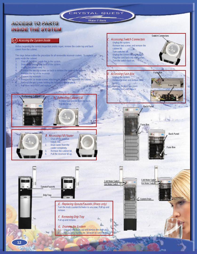
Before beginning the service inspection and/or repair, remove the cooler top and back covers from the cabinet.
The steps below outline the procedure for all removable reservoir coolers. To replace parts inside the cabinet:
Shut off the water supply line to the system.1. Drain water through the back of the system.2. Unplug the power cord.3. Remove the two top screws on back to remove the cover of the system.4. Remove the top of the reservoir.5. Remove the reservoir.6. Remove the six inside screws attaching the back of the system to the cabinet.7. Remove the two screws holding the fuse box cover in place.8. Pull fuses to remove and replace.9.
ACCESS TO PARTSINSIDE THE SYSTEM
B. Accessing Fill FloaterShut off the water at 1. supply line.Drain water from the 2. cooler completely.Remove the cabinet lid.3. Pull the reservoir lid up.4.
Removing Cabinet Lid A. Removing Cabinet LidRemove two screws from the back.1. Pull the lid up.2.
C. Accessing Switch ConnectorsUnplug the system.1. Remove two screws and remove the 2. cabinet lid.Turn switches off.3. Unplug the connector and replug.4. Plug the cord back into wall socket.5. Turn the switch back on.6.
Switch Connectors
D. Accessing Fuse BoxUnplug the system.1. Remove screws and remove back 2. panel.Remove the fuse box cover.3. Remove fuse and replace.4.
Fuse Box
Fuse Box
Back Panel
Fuse Box
Back Panel
Fuse Box
Acessing the System Inside17
Spouts/Faucets
Drip Tray
E.ReplacingSpouts/Faucets(Sharponly)Turn the knob counterclockwise to unscrew. Pull up and remove.
F. Removing Drip TrayPull up and remove.
G. Draining the SystemUnscrew the drain cap and remove the drain plug.1. Place a pan, bucket, etc. beneath to catch water.2.
Cold Water SwitchHot Water Switch
System Drain System Drain
Cold Water SwitchHot Water Switch
12
ACCESS TO HEATING RESERVOIR
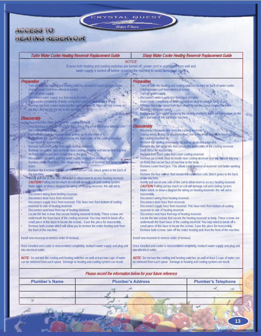
Turbo Water Cooler Heating Reservoir Replacement Guide Sharp Water Cooler Heating Reservoir Replacement GuideNOTICE:
Ensurebothheatingandcoolingswitchesareturnedoff,powercordisunpluggedfromwallandwater supply is turned off before servicing the machine to avoid damage or injury.
PreparationTurn off both the heating and cooling switches located on back of water cooler.•Unplug power cord from electrical socket.•Turn off water supply.•Disconnect water supply line from back of cooler.•Drain cooler completely of water using drain plug located on back of unit.•Remove top from cooler, exposing the cooling reservoir; there are two screws on •the back that secure the top to the machine.
DisassemblyDisconnect the water line from the cooling reservoir.•Unplugwiringatplugforelectronicfloat;thisisthesmallblackwirefeedingfrom•the cooling reservoir lid.Remove the cooling reservoir lid by pulling up on one edge of it.•Remove the two metal ties that secure the foam sides of the cooling reservoir. •Save these for reassembly.Remove both foam sides that cover cooling reservoir.•Remove six screws (two on inside near cooling reservoir and two behind drip tray •on front) that secure face of machine to the body.Disconnect cold water and hot water supply hoses from inside of face.•Remove cooler front face. This allows easy removal of reservoir and better working •room.Remove the 4 screws that secure the condenser coils (black grate) to the back of •the machine.Gently pull out on one side of the coil to allow room to access heating reservoir. •CAUTION: Pulling out too much on coil will damage coil and cooling system.Make labels or draw a diagram for wiring on heating reservoir; this will aid in •reassembly.Disconnect wiring from heating reservoir.•Disconnect drain hose from reservoir.•Disconnect supply hose from reservoir. This hose runs from bottom of cooling •reservoir to side of heating reservoir.Disconnect vent hose from top of heating reservoir.•Locate the two screws that secure heating reservoir to body. These screws are •underneath the foam base of the cooling reservoir. You may need to break off a small piece of this base to locate the screws. Save this piece for reassembly.Remove both screws which will allow you to remove the entire heating tank from •the front of the machine.
Install new reservoir in reverse order of removal.
Once installed and cooler is reassembled completely, reattach water supply and plug unit into electrical outlet.
NOTE: Do not turn the cooling and heating switches on until at least two cups of water can be retrieved from each spout. Damage to heating and cooling system can result.
PreparationTurn off both the heating and cooling switches located on back of water cooler.•Unplug power cord from electrical socket.•Turn off water supply.•Disconnect water supply line from back of cooler.•Drain cooler completely of water using drain plug located on back of unit.•Remove hot water spout from face of unit by turning spout counterclockwise.•Remove cold water spout.•Remove top from cooler exposing the cooling reservoir; there are two screws on the •back that secure the top to the machine.
DisassemblyDisconnect the water line from the cooling reservoir.•Unplugwiringatplugforelectronicfloat;thisisthesmallblackwirefeedingfrom•the cooling reservoir lid.Remove the cooling reservoir lid by pulling up on one edge of it.•Remove the two metal ties that secure the foam sides of the cooling reservoir. •Save these for reassembly.Remove both foam sides that cover cooling reservoir.•Remove six screws (four on inside near cooling reservoir and two behind drip tray •on front) that secure face of machine to the body.Remove cooler front face. This allows easy removal of reservoir and better working •room.Remove the four screws that secure the condenser coils (black grate) to the back •of the machine.Gently pull out on one side of the coil to allow room to access heating reservoir •CAUTION: Pulling out too much on coil will damage coil and cooling system.Make labels or draw a diagram for wiring on heating reservoir; this will aid in •reassembly.Disconnect wiring from heating reservoir.•Disconnect drain hose from reservoir.•Disconnect supply hose from reservoir. This hose runs from bottom of cooling •reservoir to side of heating reservoir.Disconnect vent hose from top of heating reservoir.•Locate the two screws that secure the heating reservoir to body. These screws are •underneath the foam base of the cooling reservoir. You may need to break off a small piece of this base to locate the screws. Save this piece for reassembly.Remove both screws; take off the entire heating tank from the front of the machine.•
Install new reservoir in reverse order of removal.
Once installed and cooler is reassembled completely, reattach water supply and plug unit into electrical outlet.
NOTE: Do not turn the cooling and heating switches on until at least 2 cups of water can be retrieved from each spout. Damage to heating and cooling system can result.
Please record the information below for your future reference
Plumber’s Name Plumber’s Address Plumber’s Telephone
13
WATER COOLERS(OPTIONAL CARTRIDGES & ACCESSORIES)
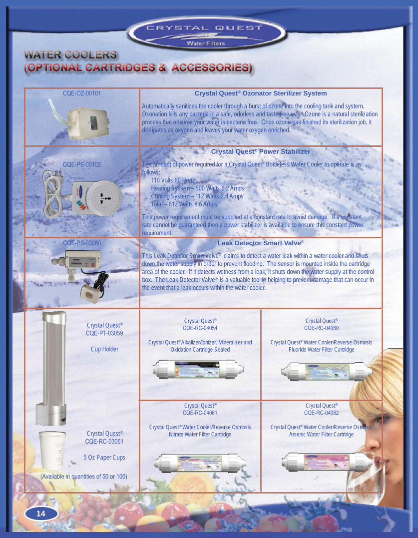
CQE-OZ-00101 Crystal Quest® Ozonator Sterilizer System
Automatically sanitizes the cooler through a burst of ozone into the cooling tank and system. Ozonation kills any bacteria in a safe, odorless and taste free way. Ozone is a natural sterilization processthatensuresyourwaterisbacteriafree.Onceozonehasfinisheditssterilizationjob,itdissipates as oxygen and leaves your water oxygen enriched.
CQE-PS-00102
Crystal Quest® Power Stabilizer
TheamountofpowerrequiredforaCrystalQuest® Bottleless Water Cooler to operate is as follows:
110 Volts 60 HertzHeating System – 500 Watts 6.2 AmpsCooling System – 112 Watts 2.4 AmpsTotal – 612 Watts 8.6 Amps
Thispowerrequirementmustbesuppliedataconstantratetoavoiddamage.Ifaconstantrate cannot be guaranteed then a power stabilizer is available to ensure this constant power requirement.
CQE-PS-03060 Leak Detector Smart Valve®
This Leak Detector Smart Valve® claims to detect a water leak within a water cooler and shuts downthewatersupplyinordertopreventflooding.Thesensorismountedinsidethecartridgearea of the cooler. If it detects wetness from a leak, it shuts down the water supply at the control box. The Leak Detector Valve® is a valuable tool in helping to prevent damage that can occur in the event that a leak occurs within the water cooler.
Crystal Quest® CQE-RC-04054
Crystal Quest® Alkalizer/Ionizer, Mineralizer and Oxidation Cartridge-Sealed
Crystal Quest® CQE-RC-04060
Crystal Quest® Water Cooler/Reverse Osmosis Fluoride Water Filter Cartridge
Crystal Quest® CQE-RC-04061
Crystal Quest® Water Cooler/Reverse Osmosis Nitrate Water Filter Cartridge
Crystal Quest® CQE-RC-04062
Crystal Quest® Water Cooler/Reverse Osmosis Arsenic Water Filter Cartridge
Crystal Quest® CQE-PT-03059
Cup Holder
(Availableinquantitiesof50or100)
Crystal Quest® CQE-RC-03061
5 Oz Paper Cups
14
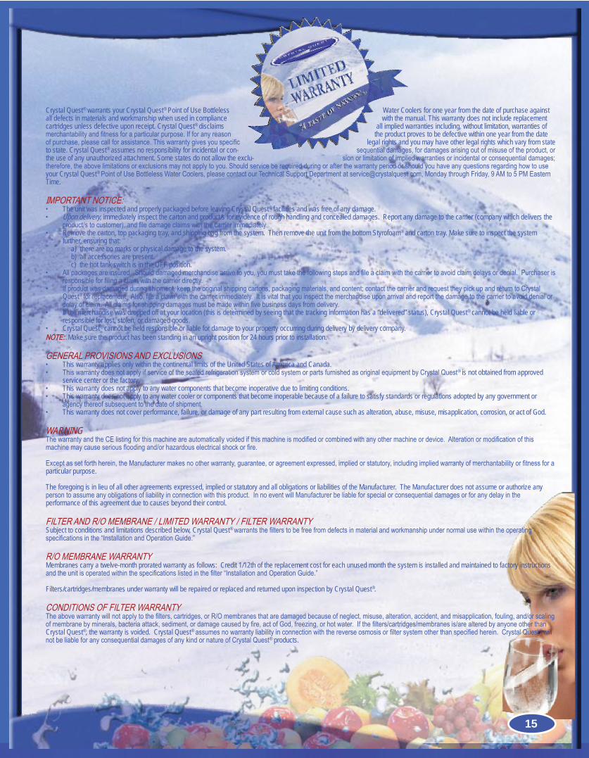
Crystal Quest® warrants your Crystal Quest® Point of Use Bottleless Water Coolers for one year from the date of purchase against all defects in materials and workmanship when used in compliance with the manual. This warranty does not include replacement cartridges unless defective upon receipt. Crystal Quest® disclaims all implied warranties including, without limitation, warranties of merchantabilityandfitnessforaparticularpurpose.Ifforanyreason the product proves to be defective within one year from the date ofpurchase,pleasecallforassistance.Thiswarrantygivesyouspecific legal rights and you may have other legal rights which vary from state to state. Crystal Quest® assumes no responsibility for incidental or con- sequentialdamages,fordamagesarisingoutofmisuseoftheproduct,orthe use of any unauthorized attachment. Some states do not allow the exclu- sionorlimitationofimpliedwarrantiesorincidentalorconsequentialdamages;therefore,theabovelimitationsorexclusionsmaynotapplytoyou.Shouldserviceberequiredduringorafterthewarrantyperiodorshouldyouhaveanyquestionsregardinghowtouseyour Crystal Quest®PointofUseBottlelessWaterCoolers,pleasecontactourTechnicalSupportDepartmentatservice@crystalquest.com,MondaythroughFriday,9AMto5PMEasternTime.
IMPORTANTNOTICE:The unit was inspected and properly packaged before leaving Crystal Quest• ® facilities and was free of any damage.Upon delivery, • immediately inspect the carton and product/s for evidence of rough handling and concealed damages. Report any damage to the carrier (company which delivers the product/stocustomer),andfiledamageclaimswiththecarrierimmediately.Remove the carton, top packaging tray, and shipping bag from the system. Then remove the unit from the bottom Styrofoam• ® and carton tray. Make sure to inspect the system further, ensuring that:
a) there are no marks or physical damage to the system.b) all accessories are present.c) the hot tank switch is in the OFF position.
Allpackagesareinsured.Shoulddamagedmerchandisearrivetoyou,youmusttakethefollowingstepsandfileaclaimwiththecarriertoavoidclaimdelaysordenial.Purchaseris•responsibleforfilingaclaimwiththecarrierdirectly.Ifproductwasdamagedduringshipment,keeptheoriginalshippingcartons,packagingmaterials,andcontent;contactthecarrierandrequesttheypickupandreturntoCrystal•Quest®forreplacement.Also,fileaclaimwiththecarrierimmediately.Itisvitalthatyouinspectthemerchandiseuponarrivalandreportthedamagetothecarriertoavoiddenialordelayofclaim.Allclaimsforshippingdamagesmustbemadewithinfivebusinessdaysfromdelivery.If the merchandise was dropped off at your location (this is determined by seeing that the tracking information has a “delivered” status), Crystal Quest• ® cannot be held liable or responsible for lost, stolen, or damaged goods.Crystal Quest• ® cannot be held responsible or liable for damage to your property occurring during delivery by delivery company.
NOTE: Make sure the product has been standing in an upright position for 24 hours prior to installation.
GENERALPROVISIONSANDEXCLUSIONSThis warranty applies only within the continental limits of the United States of America and Canada.•ThiswarrantydoesnotapplyifserviceofthesealedrefrigerationsystemorcoldsystemorpartsfurnishedasoriginalequipmentbyCrystalQuest• ® is not obtained from approved service center or the factory.This warranty does not apply to any water components that become inoperative due to limiting conditions.•This warranty does not apply to any water cooler or components that become inoperable because of a failure to satisfy standards or regulations adopted by any government or •agencythereofsubsequenttothedateofshipment.This warranty does not cover performance, failure, or damage of any part resulting from external cause such as alteration, abuse, misuse, misapplication, corrosion, or act of God.•
WARNINGThewarrantyandtheCElistingforthismachineareautomaticallyvoidedifthismachineismodifiedorcombinedwithanyothermachineordevice.Alterationormodificationofthismachinemaycauseseriousfloodingand/orhazardouselectricalshockorfire.
Exceptassetforthherein,theManufacturermakesnootherwarranty,guarantee,oragreementexpressed,impliedorstatutory,includingimpliedwarrantyofmerchantabilityorfitnessforaparticular purpose.
The foregoing is in lieu of all other agreements expressed, implied or statutory and all obligations or liabilities of the Manufacturer. The Manufacturer does not assume or authorize any persontoassumeanyobligationsofliabilityinconnectionwiththisproduct.InnoeventwillManufacturerbeliableforspecialorconsequentialdamagesorforanydelayintheperformance of this agreement due to causes beyond their control.
FILTERANDR/OMEMBRANE/LIMITEDWARRANTY/FILTERWARRANTYSubject to conditions and limitations described below, Crystal Quest®warrantsthefilterstobefreefromdefectsinmaterialandworkmanshipundernormalusewithintheoperatingspecificationsinthe“InstallationandOperationGuide.”
R/OMEMBRANEWARRANTYMembranes carry a twelve-month prorated warranty as follows: Credit 1/12th of the replacement cost for each unused month the system is installed and maintained to factory instructions andtheunitisoperatedwithinthespecificationslistedinthefilter“InstallationandOperationGuide.”
Filters/cartridges/membranes under warranty will be repaired or replaced and returned upon inspection by Crystal Quest®.
CONDITIONSOFFILTERWARRANTYTheabovewarrantywillnotapplytothefilters,cartridges,orR/Omembranesthataredamagedbecauseofneglect,misuse,alteration,accident,andmisapplication,fouling,and/orscalingofmembranebyminerals,bacteriaattack,sediment,ordamagecausedbyfire,actofGod,freezing,orhotwater.Ifthefilters/cartridges/membranesis/arealteredbyanyoneotherthanCrystal Quest®, the warranty is voided. Crystal Quest®assumesnowarrantyliabilityinconnectionwiththereverseosmosisorfiltersystemotherthanspecifiedherein.CrystalQuest® will notbeliableforanyconsequentialdamagesofanykindornatureofCrystalQuest® products.
15
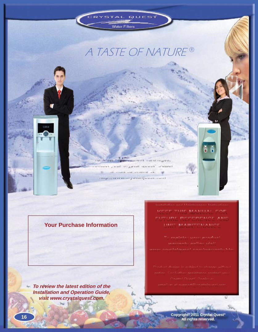
To review the latest edition of the Installation and Operation Guide,
visit www.crystalquest.com.
A TASTE OF NATURE ®
Copyright© 2011 Crystal Quest®
All rights reserved.
Your Purchase Information
Installation and Maintenance InstructionsKEEP THIS MANUAL FOR
FUTURE REFERENCE AND UNIT MAINTENANCE
Product design is subject to change without notice. For further assistance contact your
Crystal Quest® Dealer or email us at [email protected].
To register your product warranty online visit
www.crystalquest.com/warranty.htm
To order replacement cartridges, contact your Crystal Quest® Dealer
or visit us online at: http://www.crystalquest.com
16