Embed Size (px)
Citation preview
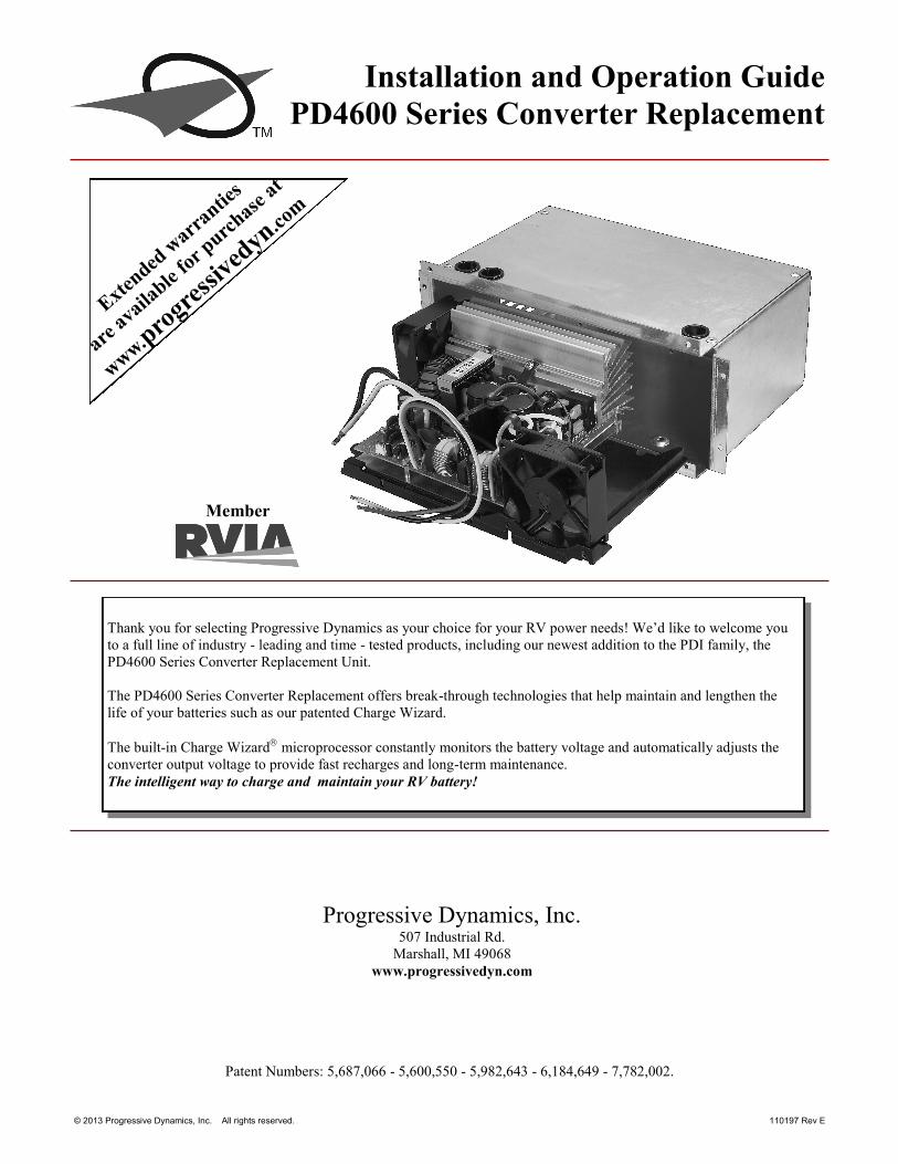
Installation and Operation Guide
PD4600 Series Converter Replacement
Member
Thank you for selecting Progressive Dynamics as your choice for your RV power needs! We’d like to welcome you
to a full line of industry - leading and time - tested products, including our newest addition to the PDI family, the
PD4600 Series Converter Replacement Unit.
The PD4600 Series Converter Replacement offers break-through technologies that help maintain and lengthen the
life of your batteries such as our patented Charge Wizard.
The built-in Charge Wizard microprocessor constantly monitors the battery voltage and automatically adjusts the
converter output voltage to provide fast recharges and long-term maintenance.
The intelligent way to charge and maintain your RV battery!
© 2013 Progressive Dynamics, Inc. All rights reserved. 110197 Rev E
Progressive Dynamics, Inc. 507 Industrial Rd.
Marshall, MI 49068
www.progressivedyn.com
Extended
warr
anties
are a
vaila
ble fo
r purc
hase
at
ww
w.pro
gress
ived
yn.com
Patent Numbers: 5,687,066 - 5,600,550 - 5,982,643 - 6,184,649 - 7,782,002.
Table of Contents
Installation Instructions 1-4
The Charge Wizard 5
Reverse Battery Protection 5
Technical Specs 5
LIMITED WARRANTY I. LIMITED WARRANTY: Progressive Dynamics, Inc. warrants its power control center to be free from defects in
material or workmanship under normal use and service; and limits the remedies to repair or replacement.
II. DURATION: This warranty shall extend for a period of two years from the original date of purchase and is valid
only within the continental limits of the United States and Canada.
III. WARRANTY EXCLUSIONS: This warranty specifically does not apply to:
A. Any product which has been repaired or altered in any way by an unauthorized person or service station;
B. Damage caused by excessive input voltage, misuse, negligence or accident; or an external force;
C. Any product which has been connected, installed or adjusted or used other than in accordance with the instruc-
tions furnished, or has had the serial number altered, defaced or removed;
D. Cost of all services performed in removing and re-installing the power converter; and
E. ANY LOST PROFITS, LOST SAVINGS, LOSS OF USE OF ENJOYMENT OR OTHER INCIDENTAL
DAMAGES ARISING OUT OF THE USE OF, OR INABILITY TO USE, THE PRODUCT. THIS IN-
CLUDES DAMAGES TO PROPERTY AND, TO THE EXTENT PERMITTED BY LAW, DAMAGES FOR
PERSONAL INJURY. THIS WARRANTY IS IN LIEU OF ALL OTHER WARRANTIES, INCLUDING
IMPLIED WARRANTIES OF MERCHANTABILITY AND FITNESS FOR A PARTICULAR PURPOSE.
IV. PROOF OF PURCHASE: A warranty claim must be accompanied by proof of the date of purchase.
V. CLAIM PROCEDURE: Upon discovery of any defect, Progressive Dynamics, Inc. shall be supplied the follow-
ing information at the address listed below:
A. Name and address of the claimant;
B. Name and model of the product;
C. Name, year and model of the recreational vehicle in which the product was installed;
D. Date of purchase; and
E. Complete description of the claimed defect.
Upon determination that a warranty claim exists (a defect in material or workmanship occurring under
normal use and service), the converter section shall be shipped postage prepaid to Progressive Dynamics, Inc. together
with proof of purchase. The product will be repaired or replaced and returned postage prepaid.
For Warranty Service Call: (269) 781-4241 ext 159
P rog res s ive Dynamics , I n c .
Page 1
INSTALLATION INSTRUCTIONS
PD4600 SERIES CONVERTER REPLACEMENT KIT
General
This retrofit kit is intended to replace existing 35, 45, and 55 Amp AC to DC power converters (depending on model).
Installation should be completed by a licensed electrician or certified RV Technician. Converter models this kit is intended to
replace are as follows, and instructions for replacement of each model are contained in this manual.
Model PD4635 (35 Amp) for replacement of:
Parallax/Magnetek model 6336
WFCO model 8935
Model PD4645 (45 Amp) for replacement of:
Parallax/Magnetek model 6345
Parallax model 7345
WFCO model 8945
Model PD4655 (55 Amp) for replacement of:
Parallax/Magnetek model 6355
Parallax model 7355
Parallax model 7155
WFCO model 8955
SAFETY FIRST!!!
To insure immediate and continued safety of installation and use of your new Progressive Dynamics Power Converter, please
adhere to the following guidelines for ALL installations:
1. Do NOT install a converter whose amperage rating is higher than the one originally installed in your application.
Doing so may cause wiring to overheat, resulting in damage to components and/or fire.
2. Disconnect all power sources prior to removal of the old converter. Power sources may include, but are not limited to:
120VAC shore power (unplug shore power cord)
Onboard generator (disconnect per manufacturer’s instructions)
12VDC battery power (disconnect negative terminal(s) from battery(ies) )
IMPORTANT! Do not discard any components or fasteners until installation is complete and all aspects of power center pass
testing. Labeling and/or organizing fasteners as they are removed will improve ease of installation, as some fasteners will be re
-used from your current configuration!

Page 2
Replacement instructions for
Parallax/Magnetek Models: 6336, 6345, 6355, 7345, 7355
Removal:
1. Disconnect all power sources as outlined on page (1) of this manual.
2. Remove front panel by removing (4) screws at bottom of panel.
3. Remove AC power section cover by removing (2) screws.
4. Disconnect the neutral (white) converter feed wire from distribution block, and hot (black) wire from AC
branch breaker. If the utility pigtail is used, remove wire nut. 5. Remove the (2) DC power distribution board mounting screws.
6. Pull the DC board outward and remove the converter+ (blue) wire from the front of the board, and the converter
- (white) wire from the BACK side of the board. Pull wires thru the hole at the bottom right of the DC power
section. 7. Remove wire from the ‘BATT POS’ lug on the old DC board, and reconnect to the ‘BATT POS+’ lug on the
new DC board. Remove the wire from the ‘BATT NEG’ lug on the FRONT of the old DC board, and reconnect
to the ‘BATT NEG-’ lug on the new DC board. Transfer branch circuit wiring and fuses in this same fashion. 8. Remove the (4) screws securing the old converter assembly to power center, and remove converter assembly.
Pull wires thru the hole at the bottom left of the AC power section.
Installation:
9. Slide new converter into power center. Route black/white/green wire-set into AC power section and black/
white wire-pair into DC section. Secure converter using (4) screws removed in step #8. 10. In the AC power section, connect new converter neutral (white) wire to neutral distribution block and converter
ground (green) wire to ground bar. Connect hot (black) wire to the existing AC branch breaker. If the utility
pigtail was used on the original installation, two short lengths of 14AWG wire and a wire nut may be used to
provide the utility pigtail. DO NOT install (2) wires into the breaker. 11. Replace AC power section cover and secure using (2) screws removed in step #3.
12. In the DC power section, route new converter DC wires behind new DC power distribution board. Connect new
converter power (black) wire to the new DC power distribution board terminal labeled ‘CONV POS+’. Connect
the negative (white) wire to the DC board terminal labeled ‘CONV NEG-’. 13. Making sure new DC feed wires remain behind DC board, secure DC board to power center using (2) screws
removed in step #5. 14. Connect 4-pin header on DC board to 4-pin header on converter assembly using 4-wire harness
(included).
15. Replace power center cover using (4) screws provided with kit.
16. Transfer DC Distribution branch circuit information to the new label provided with the retrofit kit, and adhere
label over existing label on the inside of the power center cover. Affix green Replacement Notice label in any
unused area of the power center cover.
Steps #5 & 13 Steps #3 & 11
Steps #8 & 9
Steps #4 & 10
Replacement instructions for
Parallax/Magnetek Models: 7155
Removal:
1. Disconnect all power sources as outlined on page (1) of this manual.
2. Remove front panel by removing (6) screws at bottom of panel.
3. Remove AC power section cover by removing (2) screws.
4. Disconnect the neutral (white) converter feed wire from distribution block and hot (black) wire from AC
branch breaker. If the utility pigtail is used, remove wire nut. Pull wires thru the hole at the bottom left of
the AC power section. 5. Remove the (2) DC power distribution board mounting screws.
6. Pull the DC board outward and remove the converter+ (blue) and converter- (white) wires from the board.
Pull wires thru the hole at the bottom right of the DC power section. 7. Remove ‘POS+’ wire from the old DC board, and reconnect to the terminal labeled ‘BATT POS+’ on the
new DC board. Remove the ‘NEG-’ wire from the old DC board, and reconnect to the terminal labeled
‘BATT NEG-’ on the new DC board. Transfer branch circuit wiring and fuses in this same fashion. 8. Remove the (2) screws securing the old converter assembly to power center, and remove converter assembly.
Installation:
9. Remove new converter core assembly from provided enclosure, by removing (4) screws securing converter to
enclosure and slide converter out. Discard the metal enclosure and screws as they are not used when replacing
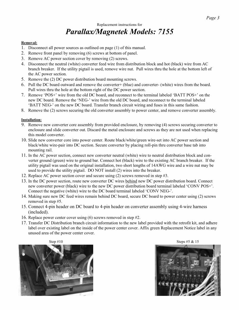
this model converter. 10. Slide new converter core into power center. Route black/white/green wire-set into AC power section and
black/white wire-pair into DC section. Secure converter by placing roll-pin thru converter base tab into
mounting rail. 11. In the AC power section, connect new converter neutral (white) wire to neutral distribution block and con-
verter ground (green) wire to ground bar. Connect hot (black) wire to the existing AC branch breaker. If the
utility pigtail was used on the original installation, two short lengths of 14AWG wire and a wire nut may be
used to provide the utility pigtail. DO NOT install (2) wires into the breaker. 12. Replace AC power section cover and secure using (2) screws removed in step #3.
13. In the DC power section, route new converter DC wires behind new DC power distribution board. Connect
new converter power (black) wire to the new DC power distribution board terminal labeled ‘CONV POS+’.
Connect the negative (white) wire to the DC board terminal labeled ‘CONV NEG-’. 14. Making sure new DC feed wires remain behind DC board, secure DC board to power center using (2) screws
removed in step #5. 15. Connect 4-pin header on DC board to 4-pin header on converter assembly using 4-wire harness
(included).
16. Replace power center cover using (6) screws removed in step #2.
17. Transfer DC Distribution branch circuit information to the new label provided with the retrofit kit, and adhere
label over existing label on the inside of the power center cover. Affix green Replacement Notice label in any
unused area of the power center cover.
Steps #5 & 15 Step #10
Page 3
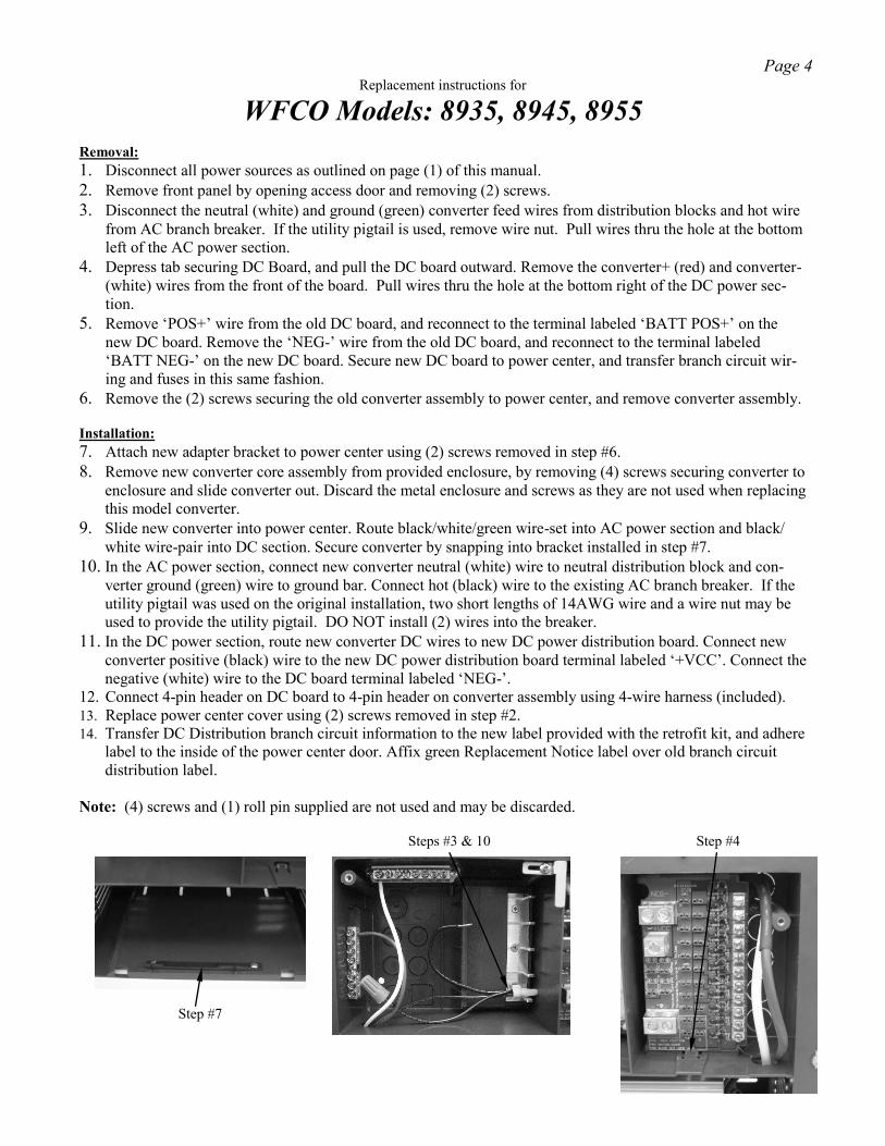
Replacement instructions for
WFCO Models: 8935, 8945, 8955
Removal:
1. Disconnect all power sources as outlined on page (1) of this manual.
2. Remove front panel by opening access door and removing (2) screws.
3. Disconnect the neutral (white) and ground (green) converter feed wires from distribution blocks and hot wire
from AC branch breaker. If the utility pigtail is used, remove wire nut. Pull wires thru the hole at the bottom
left of the AC power section. 4. Depress tab securing DC Board, and pull the DC board outward. Remove the converter+ (red) and converter-
(white) wires from the front of the board. Pull wires thru the hole at the bottom right of the DC power sec-
tion. 5. Remove ‘POS+’ wire from the old DC board, and reconnect to the terminal labeled ‘BATT POS+’ on the
new DC board. Remove the ‘NEG-’ wire from the old DC board, and reconnect to the terminal labeled
‘BATT NEG-’ on the new DC board. Secure new DC board to power center, and transfer branch circuit wir-
ing and fuses in this same fashion. 6. Remove the (2) screws securing the old converter assembly to power center, and remove converter assembly.
Installation:
7. Attach new adapter bracket to power center using (2) screws removed in step #6.
8. Remove new converter core assembly from provided enclosure, by removing (4) screws securing converter to
enclosure and slide converter out. Discard the metal enclosure and screws as they are not used when replacing
this model converter. 9. Slide new converter into power center. Route black/white/green wire-set into AC power section and black/
white wire-pair into DC section. Secure converter by snapping into bracket installed in step #7. 10. In the AC power section, connect new converter neutral (white) wire to neutral distribution block and con-
verter ground (green) wire to ground bar. Connect hot (black) wire to the existing AC branch breaker. If the
utility pigtail was used on the original installation, two short lengths of 14AWG wire and a wire nut may be
used to provide the utility pigtail. DO NOT install (2) wires into the breaker. 11. In the DC power section, route new converter DC wires to new DC power distribution board. Connect new
converter positive (black) wire to the new DC power distribution board terminal labeled ‘+VCC’. Connect the
negative (white) wire to the DC board terminal labeled ‘NEG-’. 12. Connect 4-pin header on DC board to 4-pin header on converter assembly using 4-wire harness (included).
13. Replace power center cover using (2) screws removed in step #2.
14. Transfer DC Distribution branch circuit information to the new label provided with the retrofit kit, and adhere
label to the inside of the power center door. Affix green Replacement Notice label over old branch circuit
distribution label.
Note: (4) screws and (1) roll pin supplied are not used and may be discarded.
Step #4
Step #7
Steps #3 & 10
Page 4
Page 5
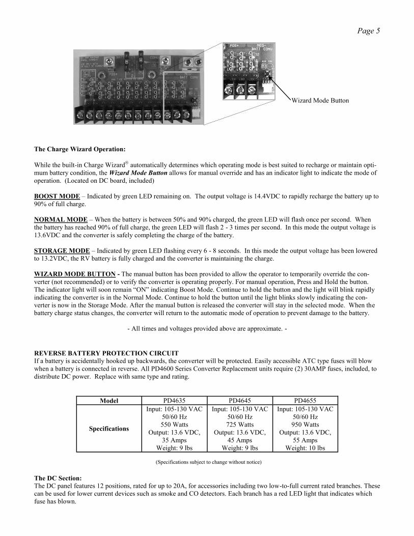
The Charge Wizard Operation:
While the built-in Charge Wizard automatically determines which operating mode is best suited to recharge or maintain opti-
mum battery condition, the Wizard Mode Button allows for manual override and has an indicator light to indicate the mode of
operation. (Located on DC board, included)
BOOST MODE – Indicated by green LED remaining on. The output voltage is 14.4VDC to rapidly recharge the battery up to
90% of full charge.
NORMAL MODE – When the battery is between 50% and 90% charged, the green LED will flash once per second. When
the battery has reached 90% of full charge, the green LED will flash 2 - 3 times per second. In this mode the output voltage is
13.6VDC and the converter is safely completing the charge of the battery.
STORAGE MODE – Indicated by green LED flashing every 6 - 8 seconds. In this mode the output voltage has been lowered
to 13.2VDC, the RV battery is fully charged and the converter is maintaining the charge.
WIZARD MODE BUTTON - The manual button has been provided to allow the operator to temporarily override the con-
verter (not recommended) or to verify the converter is operating properly. For manual operation, Press and Hold the button.
The indicator light will soon remain “ON” indicating Boost Mode. Continue to hold the button and the light will blink rapidly
indicating the converter is in the Normal Mode. Continue to hold the button until the light blinks slowly indicating the con-
verter is now in the Storage Mode. After the manual button is released the converter will stay in the selected mode. When the
battery charge status changes, the converter will return to the automatic mode of operation to prevent damage to the battery.
- All times and voltages provided above are approximate. -
REVERSE BATTERY PROTECTION CIRCUIT If a battery is accidentally hooked up backwards, the converter will be protected. Easily accessible ATC type fuses will blow
when a battery is connected in reverse. All PD4600 Series Converter Replacement units require (2) 30AMP fuses, included, to
distribute DC power. Replace with same type and rating.
Model PD4635 PD4645 PD4655
Specifications
Input: 105-130 VAC
50/60 Hz
550 Watts
Output: 13.6 VDC,
35 Amps
Weight: 9 lbs
Input: 105-130 VAC
50/60 Hz
725 Watts
Output: 13.6 VDC,
45 Amps
Weight: 9 lbs
Input: 105-130 VAC
50/60 Hz
950 Watts
Output: 13.6 VDC,
55 Amps
Weight: 10 lbs
(Specifications subject to change without notice)
Wizard Mode Button
The DC Section:
The DC panel features 12 positions, rated for up to 20A, for accessories including two low-to-full current rated branches. These
can be used for lower current devices such as smoke and CO detectors. Each branch has a red LED light that indicates which
fuse has blown.

P rog r ess ive Dynamics, In c . 507 Industrial Rd
Marshall, MI 49068
Visit us on the web for other great products.
www.progressivedyn.com