Embed Size (px)
Citation preview
Form 2021 Revision Date 5/1/2015
InstallationandOperatingServiceManual
FORCEDDRAFTSTEAMBOILERS
Bryan Steam LLC, 783 N. Chili Avenue, Peru, IN 46970, Phone 765.473.6651, Fax 765.473.3074 www.bryanboilers.com
Form 2021 i Revision Date 5/1/2015
Table of Contents S E C T I O N 1 – I N S T A L L A T I O N I N S T R U C T I O N S 1.1 Boiler Foundation ....................................................................................... 1 1.2 Clearances.............................................................................................. 1-2 1.3 Uncrating the Boiler ................................................................................... 3 1.4 Boiler Connections.................................................................................. 3-4
1.4.1 General 1.4.2 Steam Supply Connection 1.4.3 Feedwater Connection 1.4.4 Safety Relief Valve(s) 1.4.5 Blowdown Connection
1.5 Gas Supply Connection ......................................................................... 4-5 1.5.1 Drip Leg 1.5.2 Gas Piping Leak Test 1.5.3 Venting of Gas Train Connection
1.6 Electrical Connection ................................................................................. 5 1.7 Combustion Air Supply ........................................................................... 5-7 1.8 Chimney, Flue Pipe, and Draft Control ................................................ 7-23
1.8.1. General 1.8.2. Clearances 1.8.3. Boiler Room Pressurization 1.8.4. Acceptable Vent Types 1.8.5. Vent Connectors (Horizontal Runs) 1.8.6. Chimney & Vent Construction (Vert. Section) 1.8.7. Marking of Gas Vents 1.8.8. Venting Multiple Appliances on a Common Vent 1.8.9. Vent & Chimney Terminations 1.8.10. Automatic Vent Dampers 1.8.11. Sizing of Chimney and Vent 1.8.12. Quick Selection for Vent Sizing Charts 1.8.13. Special Applications
1.9 Burners and Gas Train ........................................................................... 23 1.10 Procedures to be Followed Before Placing Boiler in Operating ............... 24
1.10.1 Hydrostatic Test of Boilers and System 1.10.2 Test of Gas Piping
S E C T I O N 2 – S T A R T - U P A N D O P E R A T I O N 2.1 Firing Rate Adjustment ............................................................................ 25 2.2 Firing Rate Adjustment – Gas Meter Readings ....................................... 26
2.2.1 Checking Burner Input 2.3 Safety Shut-Off Devices (Flame Supervision) ......................................... 26
Form 2021 ii Revision Date 5/1/2015
Table of Contents – cont. 2.4 ..... Limit Circuit Cut-Out Test ................................................................... 26-27
2.4.1 Protective Devises 2.4.2 Water Temperature Operating Control 2.4.3 Outdoor Reset Controls 2.4.4 High Limit Control 2.4.5 Pool Temperature Control 2.4.6 Coil Limit Control 2.4.7 Low Water Cut-Off(s) 2.4.8 Combination Low Water Cut-Off & Feeder 2.4.9 Other Controls
2.5 Recommended Draft and Combustion Readings ............................... 28-29 2.5.1 Draft Adjustment – Atmospheric Gas Boilers 2.5.2 Draft Adjustment – Forced Draft Boilers 2.5.3 Combustion Adjustments – Forced Draft Burners
2.6 Operating Instructions.............................................................................. 29 2.6.1 Familiarization with Manual(s)
2.7 Maintenance Schedule ............................................................................ 29 S E C T I O N 3 – C A R E A N D M A I N T E N A N C E 3.1 Required Precautions During Temporary Use .................................... 30.31 3.2 Cleaning the Boiler and System – New Systems ............................... 31-32 3.3 System Clean Out ............................................................................... 32-33 3.4 Replacement Boiler Installations –
Protection Against Corrosion & Sediment ............................................... 33 3.5 Boiler Water Treatment ....................................................................... 33-34 3.6 External “Fire Side” Cleaning ................................................................... 34 3.7 Suggested Maintenance Schedule ..................................................... 35-36 3.8 Float – Actuated Water Level Controls .................................................... 36 3.9 Water Gauge Glasses ........................................................................ 36-37 3.10 Idle Boiler Care and Lay-up ................................................................ 37-41
Form 2021 1 Revision Date 5/1/2015
Installation Instructions Forced Draft Steam Boilers
Note: Please read the entire instruction manual before attempting installation. Insurance and local or state regulatory codes may contain additional or more stringent requirements than those contained in this manual. Installation must conform to these codes and any other authority having jurisdiction.
1.1 BOILER FOUNDATION Before uncrating, the boiler location should be prepared. The boiler should set upon a good level concrete floor. If the boiler is not level or the floor is not in good condition, a concrete foundation should be built, the dimensions being larger than the outside dimensions of the boiler base.
DO NOT INSTALL BOILER ON COMBUSTIBLE FLOORING.
IMPORTANT If the boiler is installed directly on a concrete floor where it is important that the floor be kept cool (such as an upper floor or mezzanine or when sitting over wiring conduits) set the boiler up on insulating tile or steel framework so that air may circulate underneath.
1.2 CLEARANCES See Table 1.2 for minimum clearances to wall, ceilings, or obstructions. The clearances in Table 1.2 are intended as a general recommendation only. Local codes must be applied to specific installations and the minimum clearances established accordingly. Provisions must also be made for service, accessibility and clearance for piping and electrical connections. Do not obstruct combustion air and ventilation openings with piping or any other construction. All boilers must be installed in a space that is large compared to the boiler.
NOTE ADHERE TO ALL APPLICABLE LOCAL CODES REGARDING BOILER INSTALLATION AND
CLEARANCES.
Section
1
Form 2021 2 Revision Date 5/1/2015
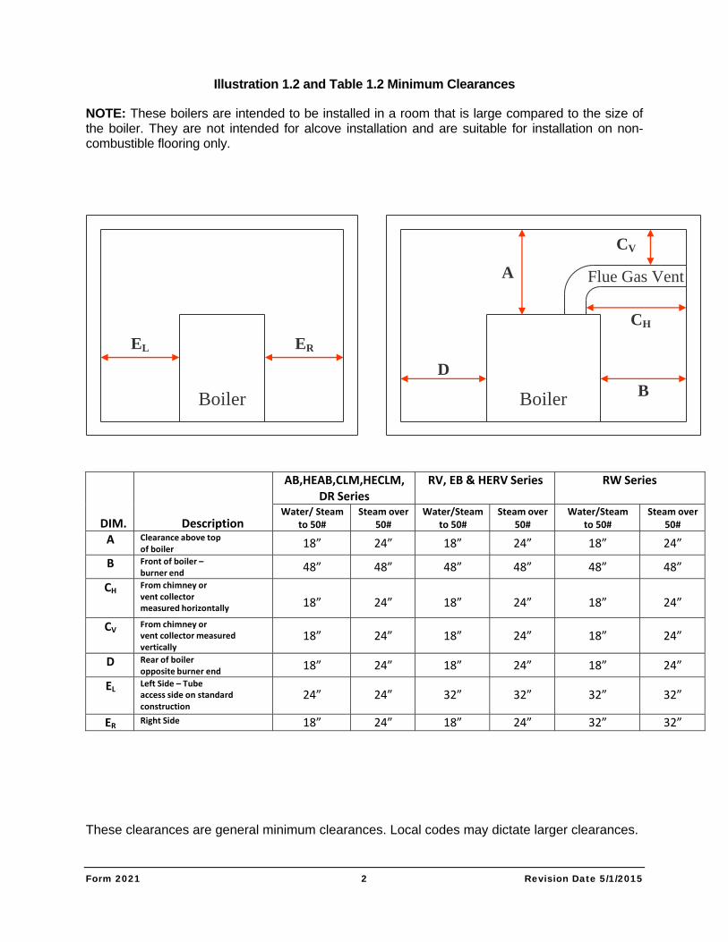
Illustration 1.2 and Table 1.2 Minimum Clearances
NOTE: These boilers are intended to be installed in a room that is large compared to the size of the boiler. They are not intended for alcove installation and are suitable for installation on non-combustible flooring only.
Boiler Boiler
EL ER
D
A
B
CV
CH
Flue Gas Vent
DIM.
Description
AB,HEAB,CLM,HECLM, DR Series
RV, EB & HERV Series RW Series
Water/ Steam to 50#
Steam over50#
Water/Steamto 50#
Steam over 50#
Water/Steam to 50#
Steam over 50#
A Clearance above top of boiler 18” 24” 18” 24” 18” 24”
B Front of boiler – burner end 48” 48” 48” 48” 48” 48”
CH From chimney or vent collector measured horizontally
18” 24” 18” 24”
18” 24”
CV From chimney or vent collector measured vertically
18” 24” 18” 24”
18” 24”
D Rear of boiler opposite burner end 18” 24” 18” 24” 18” 24”
EL Left Side – Tube access side on standard construction
24” 24” 32” 32”
32” 32”
ER Right Side 18” 24” 18” 24” 32” 32”
These clearances are general minimum clearances. Local codes may dictate larger clearances.
Form 2021 3 Revision Date 5/1/2015
1.3 UNCRATING THE BOILER Uncrate the boiler near its permanent location. Leave it on the bottom crating until ready to place it permanently. Leave the plastic shroud on the boiler until all piping work is complete, cutting holes in the plastic for access to connections.
Remove the bolts attaching the boiler to the crate at the underside of the bottom crating. Lift or slide the boiler off of the bottom crating into position. Be careful not to tip the boiler up on one corner or side, which could cause damage to jacket.
1.4 BOILER CONNECTIONS 1 . 4 . 1 G E N E R A L
Do not run any pipes along the access panel side of the boiler. Maintain clearances as shown on the dimensional drawing for servicing of the boiler tubes. Provide at least 36" from the gas train and burner, unless a larger dimension is indicated on the dimensional. All piping should be designed and installed to avoid any loadings on the boiler connections or piping.
1 . 4 . 2 S T E A M S U P P L Y C O N N E C T I O N
A steam shut-off valve must be installed between each boiler and the steam main. This valve must be of the outside screw and yoke design to allow indication from a distance whether the valve is open or closed.
1 . 4 . 3 F E E D W A T E R C O N N E C T I O N
Install a check valve and a globe valve between the feed pump and the boiler. It is also recommended to install a globe valve between the feed pump and the receiver tank. This valve can then be adjusted to bypass access pump capacity to better control the boiler feed rate.
BOILER MUST CONTROL FEED WATER
The water feed to the boiler must be controlled by the boiler-mounted water level control. It is unacceptable to use gravity return or to let the water feed be controlled by a condensate/receiver/condensate pump system. The water feed to the boiler must be controlled:
by a feed pump control which is mounted on the boiler. This control is to activate the feed pump on a boiler feed system. It will be necessary to supply such a system if not already installed
by an automatic water feeder mounted on the boiler. This is used only on systems requiring 100% make-up, such as humidification, steam process, etc.
NOTE It is not recommended to provide the make-up for a closed steam heating system to the boiler by means of a water feeder. It is preferred that system make-up be connected to the condensate return tank of a boiler feed system. A boiler feed system may be used in conjunction with an existing condensate receiver system by allowing the receiver system to pump condensate into the boiler feed system tank.
Form 2021 4 Revision Date 5/1/2015
1 . 4 . 4 S A F E T Y R E L I E F V A L V E ( S )
A connection is provided in the top of the boiler for the relief valve. The relief valve discharge piping must be the same size as the relief valve discharge opening. Avoid over-tightening as this can distort valve seats. All piping from relief valve must be independently supported with no weight carried by the valve.
1 . 4 . 5 B L O W D O W N C O N N E C T I O N
Blowdown valve(s) must be full size of the connection on the boiler. Steam boilers 15 psig and below require at least one blowdown valve. Higher-pressure boilers require two blowdown valves with one or both valves being slow opening type. Each water column and float type low water cut-off must be equipped with a blowdown valve.
1.5 GAS SUPPLY CONNECTION The installation must conform completely to the requirements of the authority having jurisdiction, or in the absence of such, requirements shall conform in the U.S. to the current National Fuel Gas Code, ANSI Z223.1-, or in Canada to the current Installation Code for Gas Burning Appliances and Equipment (CAN/CGA B149.1), or Oil Burning Equipment (CSA B139), and applicable regional regulations for the class; which should be followed carefully in all cases.
Drip leg must be installed on gas supply piping.
Consult the local gas utility company for inspection and authorization of all gas supply piping and flue connections.
The regulator vent line must be vented to outside of building on any boiler equipment with electric gas pilot ignition.
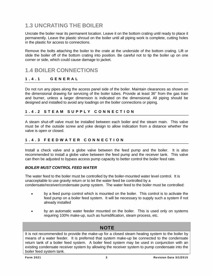
1 . 5 . 1 D R I P L E G
A drip leg, or sediment trap, must be installed in the gas supply line. See Fig. 1.5A. The gas line must be connected to a supply main at least as large as the gas train connection at the boiler. This connection should be made with a union so that the boiler gas train components and burner may be easily removed for service.
1 . 5 . 2 G A S P I P I N G L E A K T E S T
After completion of the gas piping hookup, the installation must be checked for leaks, using a soap and water solution. Disconnect the boiler and gas train from the gas supply piping during any pressure testing of the gas supply system.
1 . 5 . 3 V E N T I N G O F G A S T R A I N C O M P O N E N T S
Gas pressure regulator - The regulator must be vented to the outside air, using minimum 1/4" tubing or pipe. The vent line should terminate in a downward direction to be free of restriction.
Form 2021 5 Revision Date 5/1/2015
Diaphragm gas valves - The vent line off of these gas valves must be vented to outdoors, the same as the regulator.
Normally open vent valves - These valves must be piped to outdoors using pipe no smaller than that of the valve.
Gas pressure switches - Vent these switches to outdoors using a minimum of 1/4" tubing or piping.
F I G U R E 1 . 5 A : G A S B U R N E R C O N N E C T I O N –
NOTE: USE PIPE COMPOUND THAT IS RESISTANT TO THE ACTION OF LIQUID PETROLEUM
GAS. DO NOT USE TEFLON TAPE.
1.6 ELECTRICAL CONNECTION
IMPORTANT: All electrical connections must conform to the National Electrical Code and to all other applicable State and Local Codes. Forced draft boilers may require a high voltage connection. See boiler wiring diagram and equipment list for details.
Equipment Grounding - The boiler must be grounded in accordance with the American National Standard Electrical Code, ANSI/NFPA #70.
1.7 COMBUSTION AIR SUPPLY
IMPORTANT: Positive means for supplying an ample amount of outside air, allowing complete combustion of the gas, must be provided.
Movable combustion air dampers, automatic or manually adjustable, must be electrically interlocked with the boiler to prevent boiler operation if the dampers are closed.
Form 2021 6 Revision Date 5/1/2015
Combustion air openings must never be blocked or obstructed in any manner.
The boiler room must be at a positive or neutral pressure relative to the outdoors. A negative in the boiler room will result in downdraft problems and incomplete combustion due to the lack of air.
WARNING! Failure to provide an adequate air supply will result in boiler damage and hazardous conditions in the building (fire and asphyxiation hazard as well as equipment damage).
COMBUSTION AIR: Complete combustion of natural or propane gas requires approximately ten cubic foot of air (at sea level and 70 Deg F) for each 1,000 Btu of boiler input. In reality additional air is required to achieve complete combustion. Air is also required for the proper operation of the appliance draft diverter or barometric damper. The combustion air opening recommendations below are designed to provide the air needed for atmospheric gas fired boilers that are equipped with either draft diverters or barometric damper. Combustion air openings for boilers which are equipped with forced draft burners may be reduced to 70% of that required for atmospheric gas fired boilers. This is because the forced draft boiler is not equipped with a draft diverter (so no air is required for draft control).
COMBUSTION AIR OPENINGS - AREA REQUIRED:
OPENINGS DIRECTLY THROUGH OUTSIDE WALL - One opening within 12 inches of the ceiling plus one opening within 12 inches of the floor. Each opening must have a minimum free area of 1 square inch per 4,000 Btu of total input of all air using appliances in the room.
Example: A boiler room having two boilers with 500,000 Btu input would require two openings through an outside wall, and each opening must have at least 250 square inches of free area.
OPENINGS THROUGH VERTICAL DUCTS - One duct in the ceiling plus one duct terminating within 12 inches of the floor. Each opening must have a minimum free area of 1 square inch per 4,000 Btu of total input of all air-using appliances in the room.
Example: A boiler room having four boilers with 250,000 Btu input would require two ducts, one in ceiling and one terminating near the floor, and each opening must have at least 250 square inches of free area.
OPENINGS THROUGH HORIZONTAL DUCTS - One duct opening within 12 inches of the ceiling plus one duct opening within 12 inches of the floor. Each opening must have a minimum free area of 1 square inch per 2,000 Btu of total input for all equipment in the room. NOTE: No rectangular duct may have a dimension of less than 4 inches.
Example: A boiler room having 1 million Btu total input would require two ducts, one in ceiling and one near the floor, each opening having at least 500 square inches of free area.
Form 2021 7 Revision Date 5/1/2015
VENTILATION AIR: In addition to air needed for combustion, sufficient air must be supplied for ventilation, including air required for comfort and proper working conditions for personnel in the boiler room. In colder climates, provision should also be made to heat the boiler room, if necessary, for personnel comfort.
CAUTION Protection from combustion air contamination: Where corrosive or flammable process fumes are present in the vicinity of the boiler room or the air stream for the combustion air supply, it is essential that suitable means be provided for their safe disposal. The boiler room and the combustion air supply must not be exposed to the fumes. Such fumes include, but are not limited to, carbon monoxide, hydrogen sulfide, ammonia, chlorine, and halogenated hydrocarbons.
NOTE: Halogenated hydrocarbons are particularly injurious and corrosive after exposure to high temperatures.
1.8 CHIMNEY, FLUE PIPE & DRAFT CONTROL 1 . 8 . 1 G E N E R A L
CODE COMPLIANCE
The installation must conform to the requirements of NFPA 54, the National Gas Code (ANSI Z223.1), Part 7, "Venting of Equipment", or to the applicable requirements of all local building codes. For factory-built and listed chimney systems (such as type B vent), consult the system manufacturer's instructions for correct installation procedures. Gas vents may be of any of the construction types listed in this manual. No portion of a venting system may extend into or pass through any circulating air duct or plenum.
MINIMUM SAFE PERFORMANCE Venting systems must be designed to develop positive flow adequate to remove flue gases to the outside atmosphere. Guidelines are provided in this manual and in the National Fuel Gas Code, NFPA 54, for sizing and design of flue gas venting system. For additional reference to good practice in vent design, refer to the "Chimney, Gas Vent, and Fireplace Design" chapter of the ASHRAE Equipment Handbook.
OUTSIDE VENTS AND CHIMNEYS Outside uninsulated single wall pipe is not recommended for use in cold climates for venting gas-fired appliances since temperature differentials may cause corrosion in such pipe, as well as poor draft on start ups. When local experience indicates that condensate may be a problem, provisions should be made to drain off the condensate in the gas vent or chimney.
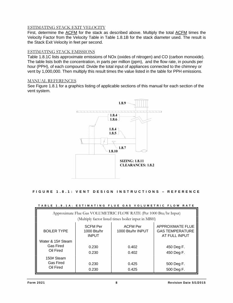
ESTIMATING FLUE GAS FLOW RATE (ACFM) Flue gas volumetric flow rate in SCFM (standard cubic feet per minute) and ACFM (actual cubic feet per minute) can be estimated by using the information in 1.8.1A. Divide the Total Input of appliances connected to the chimney or vent by 1000. Then multiply this result times the factor listed in the SCFM and ACFM table. The ACFM data is required for determining stack exit velocity and induced draft fan requirements.
Form 2021 8 Revision Date 5/1/2015
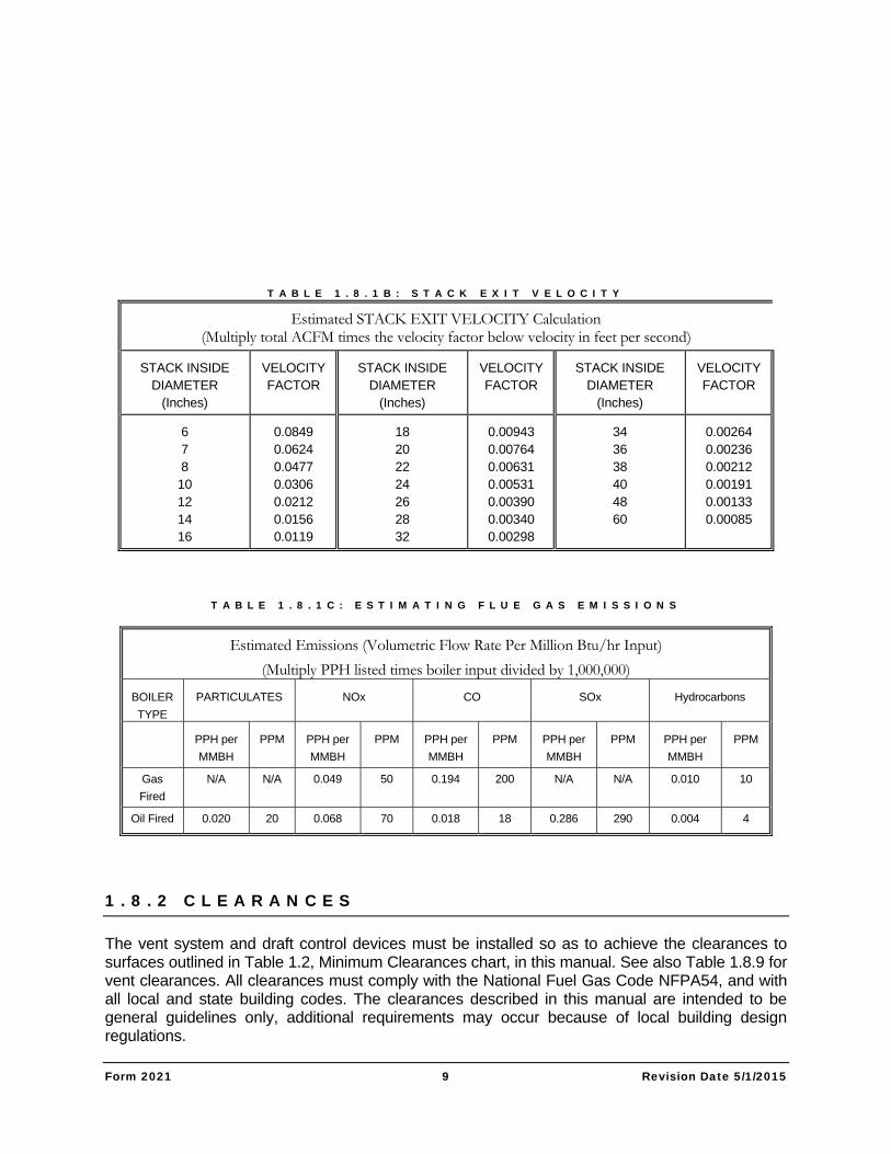
ESTIMATING STACK EXIT VELOCITY First, determine the ACFM for the stack as described above. Multiply the total ACFM times the Velocity Factor from the Velocity Table in Table 1.8.1B for the stack diameter used. The result is the Stack Exit Velocity in feet per second.
ESTIMATING STACK EMISSIONS Table 1.8.1C lists approximate emissions of NOx (oxides of nitrogen) and CO (carbon monoxide). The table lists both the concentration, in parts per million (ppm), and the flow rate, in pounds per hour (PPH), of each compound: Divide the total input of appliances connected to the chimney or vent by 1,000,000. Then multiply this result times the value listed in the table for PPH emissions.
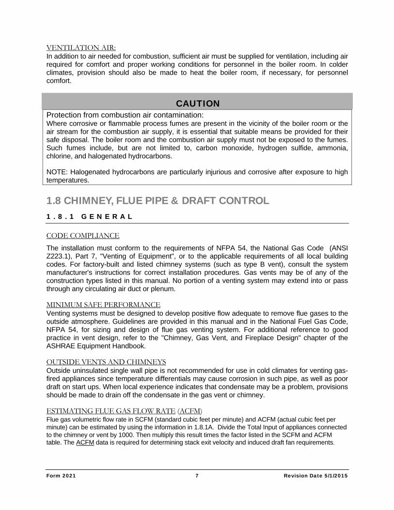
MANUAL REFERENCES See Figure 1.8.1 for a graphics listing of applicable sections of this manual for each section of the vent system.
F I G U R E 1 . 8 . 1 : V E N T D E S I G N I N S T R U C T I O N S – R E F E R E N C E
T A B L E 1 . 8 . 1 A : E S T I M A T I N G F L U E G A S V O L U M E T R I C F L O W R A T E
Approximate Flue Gas VOLUMETRIC FLOW RATE (Per 1000 Btu/hr Input) (Multiply factor listed times boiler input in MBH)
BOILER TYPE
SCFM Per 1000 Btu/hr
INPUT
ACFM Per 1000 Btu/hr INPUT
APPROXIMATE FLUE GAS TEMPERATURE
AT FULL INPUT
Water & 15# Steam Gas Fired Oil Fired
0.230
0.230
0.402
0.402
450 Deg F.
450 Deg F.
150# Steam Gas Fired Oil Fired
0.230
0.230
0.425
0.425
500 Deg F.
500 Deg F.
Form 2021 9 Revision Date 5/1/2015
T A B L E 1 . 8 . 1 B : S T A C K E X I T V E L O C I T Y
Estimated STACK EXIT VELOCITY Calculation (Multiply total ACFM times the velocity factor below velocity in feet per second)
STACK INSIDE DIAMETER
(Inches)
VELOCITY FACTOR
STACK INSIDE DIAMETER
(Inches)
VELOCITY FACTOR
STACK INSIDE DIAMETER
(Inches)
VELOCITY FACTOR
6 7 8 10 12 14 16
0.0849 0.0624 0.0477 0.0306 0.0212 0.0156 0.0119
18 20 22 24 26 28 32
0.00943 0.00764 0.00631 0.00531 0.00390 0.00340 0.00298
34 36 38 40 48 60
0.00264 0.00236 0.00212 0.00191 0.00133 0.00085
T A B L E 1 . 8 . 1 C : E S T I M A T I N G F L U E G A S E M I S S I O N S
Estimated Emissions (Volumetric Flow Rate Per Million Btu/hr Input)
(Multiply PPH listed times boiler input divided by 1,000,000)
BOILER
TYPE
PARTICULATES NOx CO SOx Hydrocarbons
PPH per
MMBH
PPM PPH per
MMBH
PPM PPH per
MMBH
PPM PPH per
MMBH
PPM PPH per
MMBH
PPM
Gas
Fired
N/A
N/A
0.049
50
0.194
200
N/A
N/A
0.010
10
Oil Fired 0.020 20 0.068 70 0.018 18 0.286 290 0.004 4
1 . 8 . 2 C L E A R A N C E S
The vent system and draft control devices must be installed so as to achieve the clearances to surfaces outlined in Table 1.2, Minimum Clearances chart, in this manual. See also Table 1.8.9 for vent clearances. All clearances must comply with the National Fuel Gas Code NFPA54, and with all local and state building codes. The clearances described in this manual are intended to be general guidelines only, additional requirements may occur because of local building design regulations.
Form 2021 10 Revision Date 5/1/2015
1 . 8 . 3 B O I L E R R O O M P R E S S U R I Z A T I O N
The boiler room must be supplied with adequate air for combustion and for proper operation of draft control devices (barometric dampers or draft diverters) as outlined in "Combustion Air Supply", Section 1.7 of this manual
WARNING
THE BOILER ROOM MUST BE MAINTAINED AT A POSITIVE OR NEUTRAL PRESSURE (RELATIVE TO OUTDOORS) AT ALL TIMES. EXHAUST FANS OR CONNECTIONS FROM THE BOILER ROOM TO ZONES OF NEGATIVE PRESSURE (AIR DUCTS, NEGATIVE PRESSURE ROOMS, ETC.) WILL CAUSE NEGATIVE PRESSURE IN THE BOILER ROOM. SUCH CONDITIONS WILL CAUSE HAZARDOUS OPERATION OF THE BOILER AND INTRODUCTION OF COMBUSTION PRODUCTS INTO THE BUILDING AIR.
IF THE BOILER ROOM MUST BE UNDER A NEGATIVE PRESSURE AT ANY TIME, AN INDUCED DRAFT FAN WILL BE REQUIRED. FURTHER, THE BOILER MUST BE PROVIDED WITH A BAROMETRIC DRAFT CONTROL - THE FAN MUST BE INTERLOCKED WITH THE BOILER AND A DRAFT PROVING SWITCH MUST BE INSTALLED TO PREVENT OPERATION OF THE BOILER IF THE FAN SHOULD FAIL TO OPERATE.
IT ALSO MAY BE ADVISABLE TO INSTALL AN AUTOMATIC VENT DAMPER IN THE VENT SYSTEM TO PREVENT BACKFLOW THROUGH THE VENT SYSTEM DURING BOILER OFF CYCLES. SEE FOLLOWING SECTION ON AUTOMATIC VENT DAMPERS.
1 . 8 . 4 A C C E P T A B L E V E N T T Y P E S
LISTED GAS VENTS Listed gas vents must be applied only on those applications for which they are listed. Type B gas vents are NOT listed for use on forced draft appliance vent systems. Installation of these vents must comply with the vent listing, with the vent manufacturer’s instructions and with complete adherence to the codes and clearances as outlined previously.
PRESSURIZED VENT SYSTEMS Some Bryan Boilers (unless specifically fitted for the application) are not suitable for operation on a pressurized vent system. Refer to Section 2 of this manual for the allowable range of vent pressure for each series. The DR, AB, EB, RV and RW series boilers are designed for pressurized vent systems. All others require a neutral pressure.
SINGLE-WALL METAL PIPE Single-wall metal pipe must be of galvanized sheet or other approved noncombustible corrosion resistant material, with minimum thickness per Table 1.8.4 from the National Fuel Gas Code NFPA 54. Single-wall metal pipe should be insulated to prevent excessive heat in the boiler room and to avoid ignition and spillage problems as well as corrosion from excessive condensation.
Form 2021 11 Revision Date 5/1/2015
MASONRY, METAL AND FACTORY BUILT CHIMNEYS Installation of factory built vents and chimneys must comply with the vent listing, with the vent manufacturer's instructions and with adherence to the codes and clearances as outlined herein. Masonry or metal chimneys must be built and installed in accordance with nationally recognized building codes or standards.
MASONRY CHIMNEYS FOR RESIDENTIAL APPLICATIONS MUST BE LINED WITH FIRE-CLAY FLUE LINING (KX C315) OR THE EQUIVALENT WITH THICKNESS NOT LESS THAN 5/16 INCH OR WITH A LINER OF OTHER APPROVED MATERIAL THAT WILL RESIST CORROSION, SOFTENING OR CRACKING FROM FLUE GASES AT TEMPERATURES UP TO 1,800°F.
EXISTING CHIMNEYS SHOULD BE INSPECTED FOR UNSAFE CONDITIONS; SUCH AS DETERIORATED MASONRY AND EXCESSIVE SOOT OR OTHER BLOCKAGE OR POTENTIAL BLOCKAGE. SEE ALSO SECTION 1.8.6.
EXISTING CHIMNEYS MUST BE PROPERLY SIZED FOR THE FLUE GAS LOADING TO BE USED. THAT IS, IF AN EXISTING CHIMNEY IS USED FOR A SMALLER TOTAL INPUT THAN ITS ORIGINAL DESIGN, A LINER OR VENT IS REQUIRED. THE USE OF A PROPERLY SIZED GAS VENT OR LINER WILL PREVENT DETERIORATION OF THE CHIMNEY DUE TO THE EXCESSIVE CONDENSATION THAT RESULTS ON OVERSIZED SYSTEMS.
WARNING UNDER NO CIRCUMSTANCES SHOULD THE FLUE PIPE BE CONNECTED TO THE
CHIMNEY OF AN OPEN FIREPLACE
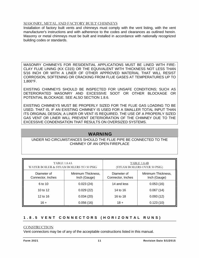
TABLE 1.8.4A WATER BOILER & STEAM BOILERS TO 50 PSIG
TABLE 1.8.4B (STEAM BOILERS OVER 50 PSIG)
Diameter of Connector, Inches
Minimum Thickness, Inch (Gauge)
Diameter of Connector, Inches
Minimum Thickness, Inch (Gauge)
6 to 10 0.023 (24) 14 and less 0.053 (16)
10 to 12 0.029 (22) 14 to 16 0.067 (14)
12 to 16 0.034 (20) 16 to 18 0.093 (12)
16 + 0.056 (16) 18 + 0.123 (10)
1 . 8 . 5 V E N T C O N N E C T O R S ( H O R I Z O N T A L R U N S )
CONSTRUCTION Vent connectors may be of any of the acceptable constructions listed in this manual.
Form 2021 12 Revision Date 5/1/2015
AVOID UNNECESSARY BENDS The vent connector must be installed so as to avoid turns or other construction features which create excessive resistance to flow of flue gases.
JOINTS Vent connectors must be firmly attached to draft diverter outlets or boiler flue collars by sheet metal screws or other approved means. Vent connectors of Type B vent material must be assembled in accordance with the vent manufacturer's instructions. Joints between sections of connector piping must be fastened using sheet metal screws or other approved means.
SLOPE OR VENT CONNECTOR The vent connector must be installed without any dips or sags and must slope upward at least 1/4 inch per foot.
LENGTH OF VENT CONNECTOR The vent connector must be as short as possible and the boiler close as practical to the chimney or vent.
The horizontal run of an uninsulated vent connector to a natural draft chimney or vent servicing a single appliance must not be more than 75% of the height of the chimney or vent above the vent connector.
The horizontal run of an insulated vent connector to a natural draft chimney or vent servicing a single appliance must not exceed 100% of the height of the chimney or vent above the vent connector.
SUPPORT OF VENT CONNECTOR The vent connector must be supported in accordance with the vent manufacturer's instructions and listing and with all applicable codes. Support should also be independent of the boiler or the draft diverter (when used). The vent connector must be: supported for the design and weight of the materials employed, maintain clearances, prevent physical damage and separation of joints, and to prevent sagging of the vent connector. Supports should usually be overhead hangers, and of load bearing capacity appropriate for the weight involved.
LOCATION When the vent connector used for an appliance having a draft hood must be located in or pass through a crawl space or other area difficult to access or which may be cold, that portion of the vent connector must be of listed double wall Type B gas vent material, or of material having equivalent insulation qualities. Single wall metal pipe used as a vent connector must not pass through any floor or ceiling.
CHIMNEY CONNECTION In entering a passageway in a masonry or metal chimney, the vent connector must be installed above the extreme bottom to avoid stoppage. Means must be employed which will prevent the vent connector from protruding so far as to restrict the space between its end and the opposite wall of the chimney. A thimble or slip joint may be used to facilitate removal of the vent connector. The vent connector must be firmly attached to or inserted into the thimble or slip joint to prevent the vent connector from falling out.
DAMPERS
Form 2021 13 Revision Date 5/1/2015
Manually operated dampers must not be placed in the vent connector. This does not exclude the use of fixed baffles, locking quadrant dampers that are welded in a fixed position or automatic vent damper (when properly installed and interlocked with the boiler gas controls).
USE OF THIMBLES Vent connectors made of single wall metal pipe must not pass through any combustible wall unless they are guarded at the point of passage by ventilated metal thimbles 6” larger in diameter than the vent connector. This may be done only on water boilers and steam boilers rated for operation at no higher than 50 psig.
SINGLE WALL METAL VENT PIPE USED TO VENT STEAM BOILERS OPERATING OVER 50 PSIG MUST NOT PASS THOUGH WALLS OR PARTITIONS CONSTRUCTED OF COMBUSTIBLE MATERIAL.
1.8.6 CHIMNEY & VENT CONSTRUCTION (VERTICAL SECTION)
INSTALLATION OF FACTORY BUILT SYSTEMS Listed gas vents and factory built chimneys must be installed in accordance with their listings and the manufacturer's instructions. Vents and venting systems passing through roofs must extend through the roof flashing, roof thimble or roof jack.
INSTALLATION OF MASONRY OR METAL CHIMNEYS Masonry or metal chimneys must be built in accordance with nationally recognized building codes and standards.
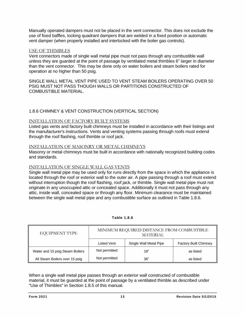
INSTALLATION OF SINGLE WALL GAS VENTS Single wall metal pipe may be used only for runs directly from the space in which the appliance is located through the roof or exterior wall to the outer air. A pipe passing through a roof must extend without interruption though the roof flashing, roof jack, or thimble. Single wall metal pipe must not originate in any unoccupied attic or concealed space. Additionally it must not pass through any attic, inside wall, concealed space or through any floor. Minimum clearance must be maintained between the single wall metal pipe and any combustible surface as outlined in Table 1.8.6.
Table 1.8.6
EQUIPMENT TYPE
MINIMUM REQUIRED DISTANCE FROM COMBUSTIBLE MATERIAL
Listed Vent Single Wall Metal Pipe Factory Built Chimney
Water and 15 psig Steam Boilers Not permitted 18” as listed
All Steam Boilers over 15 psig Not permitted 36” as listed
When a single wall metal pipe passes through an exterior wall constructed of combustible material, it must be guarded at the point of passage by a ventilated thimble as described under "Use of Thimbles" in Section 1.8.5 of this manual.
Form 2021 14 Revision Date 5/1/2015
Alternatively, a non-ventilating thimble not less than 18" above and 6" below the roof (with the annular space open at the bottom and closed at the top) may be used.
INSPECTIONS OF CHIMNEYS Before connection of a vent connector to a chimney, the chimney passageway must be examined to ascertain that it is clear and free of obstructions. Cleanouts must be constructed such that they will remain tightly closed when not in use. Tee fittings used as cleanouts or condensate drains must have tight fitting caps to prevent entrance of air into the chimney at such points. When an existing masonry chimney is unlined and local experience indicates that vent gas condensate may be a problem, an approved liner or another vent must be installed. When inspection reveals that an existing chimney is not safe for the intended application, it must be rebuilt to conform to nationally recognized standards, relined with a suitable liner, or replaced with a gas vent or chimney suitable for the appliances to be attached.
SUPPORT OF CHIMNEYS AND VENTS All portions of chimneys must be adequately supported for the design and weight of the materials employed. Listed factory built chimneys must be supported and spaced in accordance with their listings and the chimney or gas vent manufacturer's recommendation. THE GAS VENT OR CHIMNEY MUST BE SUPPORTED INDEPENDENTLY OF THE BOILER TOP.
1 . 8 . 7 M A R K I N G O F G A S V E N T S
In those localities where solid and liquid fuels are used extensively, gas vents must be plainly and permanently identified by a label reading: "This gas vent is for appliances which burn gas only. Do not connect to incinerators or solid or liquid fuel burning appliances."
This label must be attached to the wall or ceiling at a point near where the gas vent connector enters the wall, ceiling or chimney. The authority having jurisdiction must determine whether their area constitutes such a locality.
1 . 8 . 8 V E N T I N G M U L T I P L E A P P L I A N C E S O N A C O M M O N V E N T
COMMON GAS VENT When two or more openings (for vent connectors) are provided in a chimney or gas vent, the opening should be at different levels. They should never be opposite one another.
When two vent connectors enter the same gas vent or chimney, the smaller of the two should enter at the highest position possible.
PRESSURIZED VENTS OR VENT CONNECTORS
DO NOT CONNECT THE FLUE OF AN APPLIANCE VENTED BY NATURAL DRAFT TO A VENT SYSTEM THAT OPERATES UNDER A POSITIVE PRESSURE.
SOLID FUEL APPLIANCE VENTS
Gas appliances must not be vented to a vent or a chimney that serves a solid fuel-burning appliance.
Form 2021 15 Revision Date 5/1/2015
1 . 8 . 9 V E N T A N D C H I M N E Y T E R M I N A T I O N S
HEIGHT ABOVE ROOF AND OBSTACLE WATER BOILERS AND LOW PRESSURE STEAM BOILERS: No less than 3 feet above the roof and no less than 2 feet above any parapet or obstacle closer than 10 feet from the vent outlet (Reference NFPA 211).
HIGH PRESSURE (OVER 15 PSIG) STEAM BOILERS: No less than 10 feet higher than any portion of any building within a distance of 25 feet from the vent (Reference NFPA 211).
MINIMUM HEIGHT ABOVE DRAFT CONTROL Chimneys and gas vents must extend at least 5 feet above the highest connected draft diverter outlet, barometric draft control or any appliance flue outlet.
CLEARANCE FROM AIR INLETS The vent or chimney must terminate no less than 3 feet above any forced air inlet within a distance of 10 feet. It must terminate no less than 1 foot above, or 4 feet below, or 4 feet horizontally from, any door, window or gravity air inlet into a building.
CLEARANCE FROM PUBLIC WALKWAYS The vent exit of a mechanical draft system must be at least 7 feet above grade when located next to public walkways.
PROTECTION OF BUILDING MATERIALS FROM POSSIBLE CORROSION OR DISCOLORATION FROM FLUE PRODUCTS The products of combustion from gas or oil contain potentially corrosive gases and high temperatures. For this reason, the chimney or vent exit must be designed to prevent exposure of the building materials to the flue products. Failure to do so may result in deterioration or discoloration of building materials.
VENT SUPPORT The gas vent or chimney must be securely positioned and supported. Guy wires or other reliable means must be used to prevent movement of the vent.
PROTECTION AGAINST BLOCKAGE OR OBSTRUCTION The chimney or vent exit design must prevent any possibility of blockage by snow or by any other obstruction.
POWER VENTED EXHAUST SYSTEMS When these are used, such mechanical exhaust devices must be electrically interlocked with all appliances on the vent system. The circuit must prevent the operation of any appliance on the system if the hood or exhaust system is not in operation.
STACK CAPS Every gas vent must be supplied with an approved vent cap that will prevent the entrance of rain or other precipitation into the vent. Failure to provide such a cap may cause severe boiler corrosion or combustion problems or both.
Form 2021 16 Revision Date 5/1/2015
Listed gas vents must be terminated with a listed cap, approved for use with the particular gas vent.
Listed vent caps or roof assemblies must have a rated venting capacity no less than the vent.
Single wall vents must terminate in an approved cap which does not obstruct the exit. The preferred type of cap for natural draft vented atmospheric boilers is the Briedert Cap. This is because of the protection this cap provides against wind generated downdrafts.
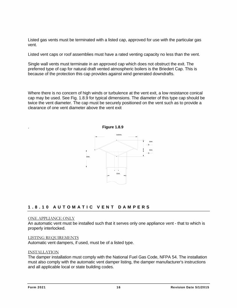
Where there is no concern of high winds or turbulence at the vent exit, a low resistance conical cap may be used. See Fig. 1.8.9 for typical dimensions. The diameter of this type cap should be twice the vent diameter. The cap must be securely positioned on the vent such as to provide a clearance of one vent diameter above the vent exit
. Figure 1.8.9
1 . 8 . 1 0 A U T O M A T I C V E N T D A M P E R S
ONE APPLIANCE ONLY An automatic vent must be installed such that it serves only one appliance vent - that to which is properly interlocked.
LISTING REQUIREMENTS Automatic vent dampers, if used, must be of a listed type.
INSTALLATION The damper installation must comply with the National Fuel Gas Code, NFPA 54. The installation must also comply with the automatic vent damper listing, the damper manufacturer's instructions and all applicable local or state building codes.
Form 2021 17 Revision Date 5/1/2015
AUTOMATIC VENT DAMPERS MUST BE INSTALLED ONLY BY QUALIFIED SERVICE TECHNICIANS. FAILURE TO PROPERLY INSTALL A VENT DAMPER WILL CREATE A
SEVERE HAZARD.
PERFORMANCE TEST The damper must be tested after installation to assure its proper and safe operation.
AUTOMATIC VENT DAMPERS MUST BE IN THE OPEN POSITION AT ANY TIME THE APPLIANCE MAIN GAS VALVE IS ENERGIZED
1 . 8 . 1 1 S I Z I N G O F C H I M N E Y A N D V E N T
The flue system calculations, which follow in Section 1.8.12, are applicable to double-wall or insulated single wall breechings (vent connectors) and stacks (vents). Do not apply these calculations to uninsulated vent systems.
HIGH ALTITUDES At altitudes of 2000 feet and higher, atmospheric boilers must be derated. The amount of derate required by the National Fuel Gas Code is 4% per 1000 feet above sea level. Boilers that are shipped from the factory prepared for these altitudes have the gas orifices properly sized for this derate. The altitude and gas Btu content for which the boilers have been constructed is listed on the Equipment List/Submittal Data in the boiler manual. The boilers will also be provided with a label indicating that they have been prepared for high altitude. If a boiler is to be installed at an altitude other than that for which it was factory built, orifices must be replaced to properly adjust the gas input. Consult the factory or the local Bryan Representative for the proper parts. For the purpose of vent system sizing, assume full input and determine sizing as if at sea level. The derate factor of 4% per 1000 feet above sea level accounts for the increased volume per Btu/hr of flue products at high altitude. INDUCED DRAFT FANS Occasionally, the characteristics of an installation are such that a natural draft vent system will not suffice. In such cases, induced draft may be used. The vent system is then sized with an available "pumping" action equal to the total theoretical draft plus the static pressure capability of the induced draft fan. This will result in a smaller diameter vent than for a natural draft system. Sizing of induced draft fans should be done using the recommendations of the fan manufacturer and the ASHRAE Handbook.
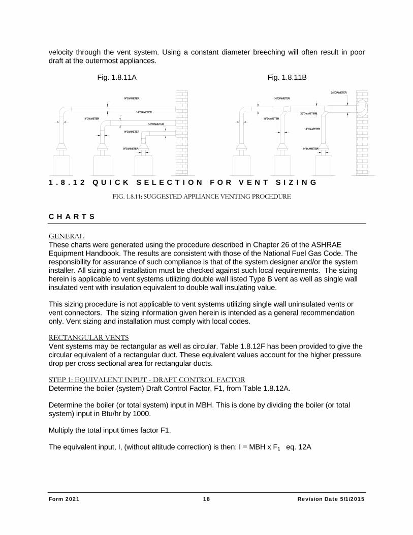
MULTIPLE APPLIANCE INSTALLATIONS Bryan recommends that boilers and other gas appliances be individually vented when possible. See figure 1.8.11A. Individual venting provides better draft control and fuel efficiency, and is less likely to cause condensation in the system. When individual venting is not possible, boilers may be vented to a common breeching (vent connector). See Fig. 1.8.11B for recommended design of such a system. Note that connections of individual boiler or appliance vents into the common breeching should be done with 45 Deg F elbows and not by "bullheading" directly into the vent connector at 90 Deg F angles. "Bullhead" connections generally cause excessive turbulence and poor draft conditions. On vent connectors serving multiple appliances, the diameter of the piping should be increased at each appliance's entrance so as to provide a relatively constant flue gas
Form 2021 18 Revision Date 5/1/2015
velocity through the vent system. Using a constant diameter breeching will often result in poor draft at the outermost appliances.
Fig. 1.8.11A Fig. 1.8.11B
1 . 8 . 1 2 Q U I C K S E L E C T I O N F O R V E N T S I Z I N G
C H A R T S
GENERAL These charts were generated using the procedure described in Chapter 26 of the ASHRAE Equipment Handbook. The results are consistent with those of the National Fuel Gas Code. The responsibility for assurance of such compliance is that of the system designer and/or the system installer. All sizing and installation must be checked against such local requirements. The sizing herein is applicable to vent systems utilizing double wall listed Type B vent as well as single wall insulated vent with insulation equivalent to double wall insulating value.
This sizing procedure is not applicable to vent systems utilizing single wall uninsulated vents or vent connectors. The sizing information given herein is intended as a general recommendation only. Vent sizing and installation must comply with local codes.
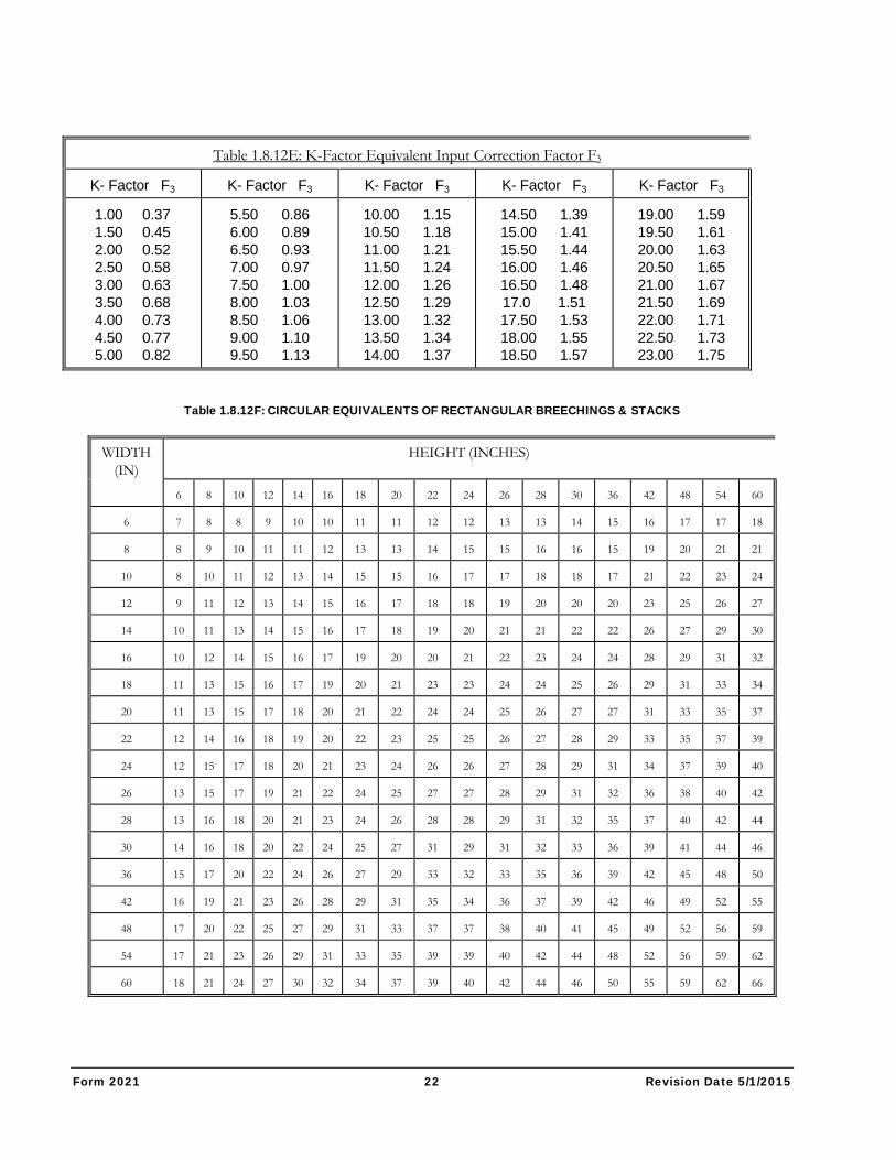
RECTANGULAR VENTS Vent systems may be rectangular as well as circular. Table 1.8.12F has been provided to give the circular equivalent of a rectangular duct. These equivalent values account for the higher pressure drop per cross sectional area for rectangular ducts.
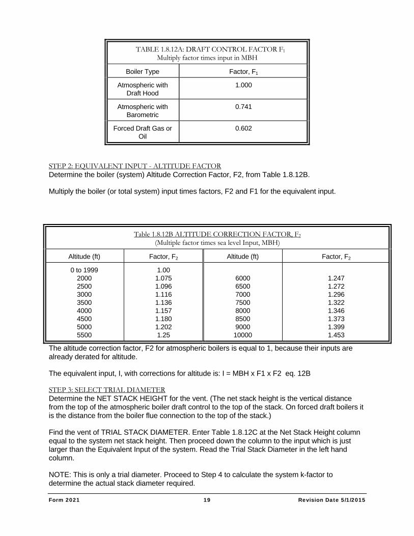
STEP 1: EQUIVALENT INPUT - DRAFT CONTROL FACTOR Determine the boiler (system) Draft Control Factor, F1, from Table 1.8.12A.
Determine the boiler (or total system) input in MBH. This is done by dividing the boiler (or total system) input in Btu/hr by 1000.
Multiply the total input times factor F1.
The equivalent input, I, (without altitude correction) is then: I = MBH x F1 eq. 12A
FIG. 1.8.11: SUGGESTED APPLIANCE VENTING PROCEDURE
Form 2021 19 Revision Date 5/1/2015
TABLE 1.8.12A: DRAFT CONTROL FACTOR F1 Multiply factor times input in MBH
Boiler Type Factor, F1
Atmospheric with Draft Hood
1.000
Atmospheric with Barometric
0.741
Forced Draft Gas or Oil
0.602
STEP 2: EQUIVALENT INPUT - ALTITUDE FACTOR Determine the boiler (system) Altitude Correction Factor, F2, from Table 1.8.12B.
Multiply the boiler (or total system) input times factors, F2 and F1 for the equivalent input.
The altitude correction factor, F2 for atmospheric boilers is equal to 1, because their inputs are already derated for altitude.
The equivalent input, I, with corrections for altitude is: I = MBH x F1 x F2 eq. 12B
STEP 3: SELECT TRIAL DIAMETER Determine the NET STACK HEIGHT for the vent. (The net stack height is the vertical distance from the top of the atmospheric boiler draft control to the top of the stack. On forced draft boilers it is the distance from the boiler flue connection to the top of the stack.)
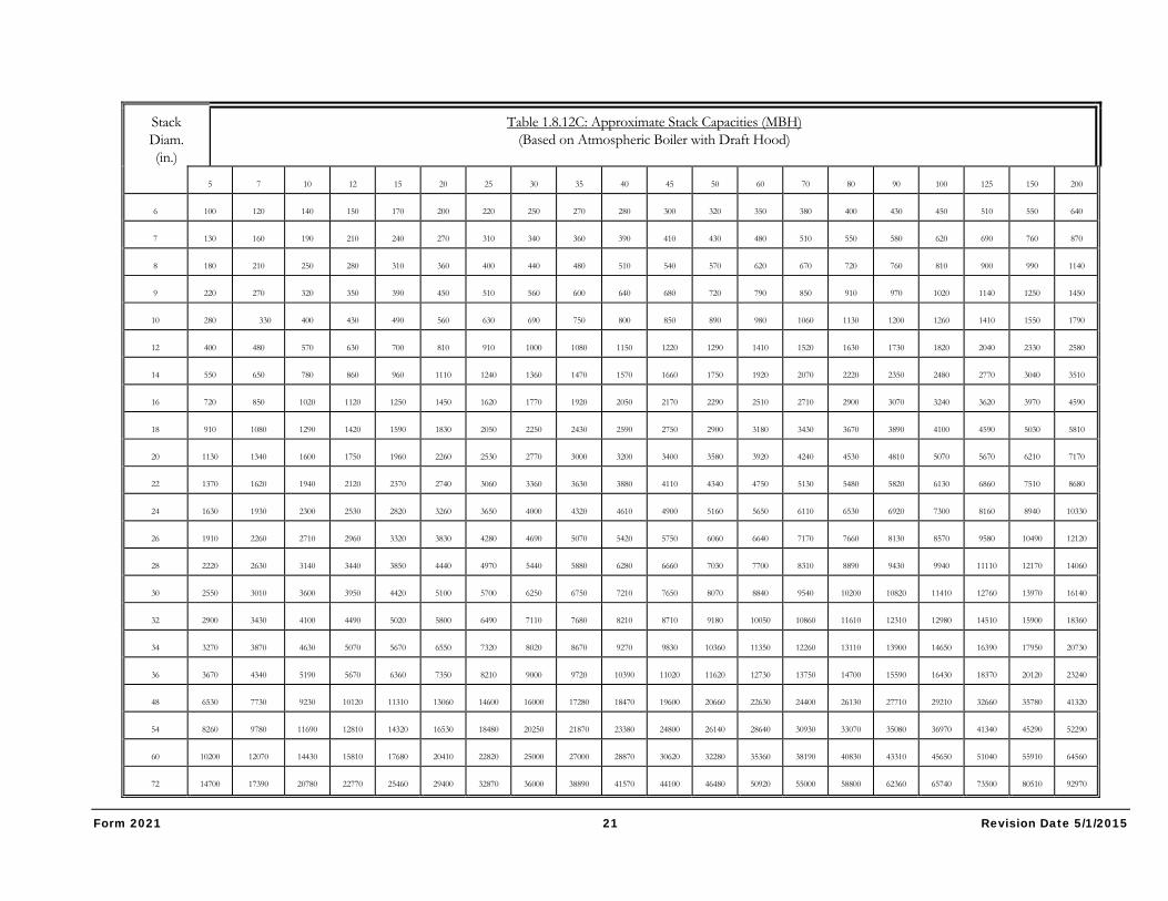
Find the vent of TRIAL STACK DIAMETER. Enter Table 1.8.12C at the Net Stack Height column equal to the system net stack height. Then proceed down the column to the input which is just larger than the Equivalent Input of the system. Read the Trial Stack Diameter in the left hand column.
NOTE: This is only a trial diameter. Proceed to Step 4 to calculate the system k-factor to determine the actual stack diameter required.
Table 1.8.12B ALTITUDE CORRECTION FACTOR, F2 (Multiple factor times sea level Input, MBH)
Altitude (ft) Factor, F2 Altitude (ft) Factor, F2
0 to 1999 2000 2500 3000 3500 4000 4500 5000 5500
1.00 1.075 1.096 1.116 1.136 1.157 1.180 1.202 1.25
6000 6500 7000 7500 8000 8500 9000 10000
1.247 1.272 1.296 1.322 1.346 1.373 1.399 1.453
Form 2021 20 Revision Date 5/1/2015
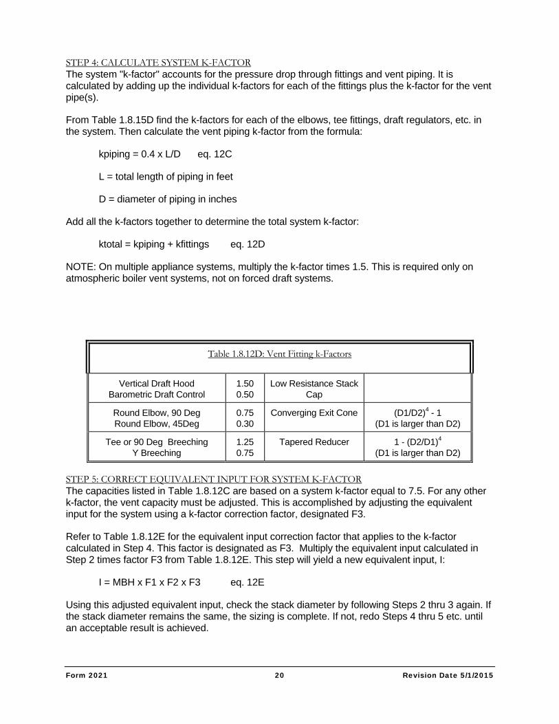
STEP 4: CALCULATE SYSTEM K-FACTOR The system "k-factor" accounts for the pressure drop through fittings and vent piping. It is calculated by adding up the individual k-factors for each of the fittings plus the k-factor for the vent pipe(s).
From Table 1.8.15D find the k-factors for each of the elbows, tee fittings, draft regulators, etc. in the system. Then calculate the vent piping k-factor from the formula:
kpiping = 0.4 x L/D eq. 12C
L = total length of piping in feet
D = diameter of piping in inches
Add all the k-factors together to determine the total system k-factor:
ktotal = kpiping + kfittings eq. 12D
NOTE: On multiple appliance systems, multiply the k-factor times 1.5. This is required only on atmospheric boiler vent systems, not on forced draft systems.
Table 1.8.12D: Vent Fitting k-Factors
Vertical Draft Hood Barometric Draft Control
1.50 0.50
Low Resistance Stack Cap
Round Elbow, 90 Deg Round Elbow, 45Deg
0.75 0.30
Converging Exit Cone (D1/D2)4 - 1 (D1 is larger than D2)
Tee or 90 Deg Breeching Y Breeching
1.25 0.75
Tapered Reducer 1 - (D2/D1)4 (D1 is larger than D2)
STEP 5: CORRECT EQUIVALENT INPUT FOR SYSTEM K-FACTOR The capacities listed in Table 1.8.12C are based on a system k-factor equal to 7.5. For any other k-factor, the vent capacity must be adjusted. This is accomplished by adjusting the equivalent input for the system using a k-factor correction factor, designated F3.
Refer to Table 1.8.12E for the equivalent input correction factor that applies to the k-factor calculated in Step 4. This factor is designated as F3. Multiply the equivalent input calculated in Step 2 times factor F3 from Table 1.8.12E. This step will yield a new equivalent input, I:
I = MBH x F1 x F2 x F3 eq. 12E
Using this adjusted equivalent input, check the stack diameter by following Steps 2 thru 3 again. If the stack diameter remains the same, the sizing is complete. If not, redo Steps 4 thru 5 etc. until an acceptable result is achieved.
Form 2021 21 Revision Date 5/1/2015
Stack Diam. (in.)
Table 1.8.12C: Approximate Stack Capacities (MBH) (Based on Atmospheric Boiler with Draft Hood)
5 7 10 12 15 20 25 30 35 40 45 50 60 70 80 90 100 125 150 200
6 100 120 140 150 170 200 220 250 270 280 300 320 350 380 400 430 450 510 550 640
7 130 160 190 210 240 270 310 340 360 390 410 430 480 510 550 580 620 690 760 870
8 180 210 250 280 310 360 400 440 480 510 540 570 620 670 720 760 810 900 990 1140
9 220 270 320 350 390 450 510 560 600 640 680 720 790 850 910 970 1020 1140 1250 1450
10 280 330 400 430 490 560 630 690 750 800 850 890 980 1060 1130 1200 1260 1410 1550 1790
12 400 480 570 630 700 810 910 1000 1080 1150 1220 1290 1410 1520 1630 1730 1820 2040 2330 2580
14 550 650 780 860 960 1110 1240 1360 1470 1570 1660 1750 1920 2070 2220 2350 2480 2770 3040 3510
16 720 850 1020 1120 1250 1450 1620 1770 1920 2050 2170 2290 2510 2710 2900 3070 3240 3620 3970 4590
18 910 1080 1290 1420 1590 1830 2050 2250 2430 2590 2750 2900 3180 3430 3670 3890 4100 4590 5030 5810
20 1130 1340 1600 1750 1960 2260 2530 2770 3000 3200 3400 3580 3920 4240 4530 4810 5070 5670 6210 7170
22 1370 1620 1940 2120 2370 2740 3060 3360 3630 3880 4110 4340 4750 5130 5480 5820 6130 6860 7510 8680
24 1630 1930 2300 2530 2820 3260 3650 4000 4320 4610 4900 5160 5650 6110 6530 6920 7300 8160 8940 10330
26 1910 2260 2710 2960 3320 3830 4280 4690 5070 5420 5750 6060 6640 7170 7660 8130 8570 9580 10490 12120
28 2220 2630 3140 3440 3850 4440 4970 5440 5880 6280 6660 7030 7700 8310 8890 9430 9940 11110 12170 14060
30 2550 3010 3600 3950 4420 5100 5700 6250 6750 7210 7650 8070 8840 9540 10200 10820 11410 12760 13970 16140
32 2900 3430 4100 4490 5020 5800 6490 7110 7680 8210 8710 9180 10050 10860 11610 12310 12980 14510 15900 18360
34 3270 3870 4630 5070 5670 6550 7320 8020 8670 9270 9830 10360 11350 12260 13110 13900 14650 16390 17950 20730
36 3670 4340 5190 5670 6360 7350 8210 9000 9720 10390 11020 11620 12730 13750 14700 15590 16430 18370 20120 23240
48 6530 7730 9230 10120 11310 13060 14600 16000 17280 18470 19600 20660 22630 24400 26130 27710 29210 32660 35780 41320
54 8260 9780 11690 12810 14320 16530 18480 20250 21870 23380 24800 26140 28640 30930 33070 35080 36970 41340 45290 52290
60 10200 12070 14430 15810 17680 20410 22820 25000 27000 28870 30620 32280 35360 38190 40830 43310 45650 51040 55910 64560
72 14700 17390 20780 22770 25460 29400 32870 36000 38890 41570 44100 46480 50920 55000 58800 62360 65740 73500 80510 92970
Form 2021 22 Revision Date 5/1/2015
Table 1.8.12F: CIRCULAR EQUIVALENTS OF RECTANGULAR BREECHINGS & STACKS
WIDTH (IN)
HEIGHT (INCHES)
6 8 10 12 14 16 18 20 22 24 26 28 30 36 42 48 54 60
6 7 8 8 9 10 10 11 11 12 12 13 13 14 15 16 17 17 18
8 8 9 10 11 11 12 13 13 14 15 15 16 16 15 19 20 21 21
10 8 10 11 12 13 14 15 15 16 17 17 18 18 17 21 22 23 24
12 9 11 12 13 14 15 16 17 18 18 19 20 20 20 23 25 26 27
14 10 11 13 14 15 16 17 18 19 20 21 21 22 22 26 27 29 30
16 10 12 14 15 16 17 19 20 20 21 22 23 24 24 28 29 31 32
18 11 13 15 16 17 19 20 21 23 23 24 24 25 26 29 31 33 34
20 11 13 15 17 18 20 21 22 24 24 25 26 27 27 31 33 35 37
22 12 14 16 18 19 20 22 23 25 25 26 27 28 29 33 35 37 39
24 12 15 17 18 20 21 23 24 26 26 27 28 29 31 34 37 39 40
26 13 15 17 19 21 22 24 25 27 27 28 29 31 32 36 38 40 42
28 13 16 18 20 21 23 24 26 28 28 29 31 32 35 37 40 42 44
30 14 16 18 20 22 24 25 27 31 29 31 32 33 36 39 41 44 46
36 15 17 20 22 24 26 27 29 33 32 33 35 36 39 42 45 48 50
42 16 19 21 23 26 28 29 31 35 34 36 37 39 42 46 49 52 55
48 17 20 22 25 27 29 31 33 37 37 38 40 41 45 49 52 56 59
54 17 21 23 26 29 31 33 35 39 39 40 42 44 48 52 56 59 62
60 18 21 24 27 30 32 34 37 39 40 42 44 46 50 55 59 62 66
Table 1.8.12E: K-Factor Equivalent Input Correction Factor F3
K- Factor F3 K- Factor F3 K- Factor F3 K- Factor F3 K- Factor F3
1.00 0.37 1.50 0.45 2.00 0.52 2.50 0.58 3.00 0.63 3.50 0.68 4.00 0.73 4.50 0.77 5.00 0.82
5.50 0.86 6.00 0.89 6.50 0.93 7.00 0.97 7.50 1.00 8.00 1.03 8.50 1.06 9.00 1.10 9.50 1.13
10.00 1.15 10.50 1.18 11.00 1.21 11.50 1.24 12.00 1.26 12.50 1.29 13.00 1.32 13.50 1.34 14.00 1.37
14.50 1.39 15.00 1.41 15.50 1.44 16.00 1.46 16.50 1.48 17.0 1.51 17.50 1.53 18.00 1.55 18.50 1.57
19.00 1.59 19.50 1.61 20.00 1.63 20.50 1.65 21.00 1.67 21.50 1.69 22.00 1.71 22.50 1.73 23.00 1.75
Form 2021 23 Revision Date 5/1/2015
1 . 8 . 1 3 S P E C I A L A P P L I C A T I O N S
FLUE GAS ECONOMIZERS
When applying flue gas economizers, care must be taken to assure that:
1. Proper draft must be maintained. This requires that the gas side pressure drop be considered and that the economizer exchanger must be designed so as to allow cleaning.
2. The vent system materials must be considered regarding resistance from corrosion that might result from the lower flue gas temperature.
3. In general, it is recommended that the boiler manufacturer be consulted when a flue gas economizer is to be added.
HIGH EFFICIENCY APPLIANCES High efficiency appliances require special consideration in vent design because of the reduced stack gas temperatures. Under no circumstances can a condensing type appliance be vented into the same vent system with other appliances. The vent system for such appliances must be provided by or specified specifically by the manufacturer of the condensing appliance.
High efficiency non-condensing appliances should generally be installed only on vent systems that are resistant to corrosion from flue gas condensate. This generally requires stainless steel vent construction.
1.9 BURNERS AND GAS TRAINS GENERAL Refer to separate manual on the forced draft burner for start-up and adjustment procedures. Do not attempt to start burner when excess oil has accumulated, or when the combustion chamber is full of gas, or if chamber is very hot.
FUEL CONNECTIONS Gas supply connections must comply with the National Fuel Gas Code (NFPA 54). Oil Supply connections must comply with (NFPA 31). Any additional local or state codes must also be adhered to. Oil supply lines must be sized for the circulation rate of the burner pump.
This is referred to as the suction gear capacity of the pump. If a transfer pump is used, it must have a pumping capacity no less than the total suction gear capacity of all burner pumps on the system. Refer to Burner Manual for the suction gear capacity of standard oil pumps. Two-pipe oil systems are recommended in all cases, although a one-pipe system might be acceptable on smaller boilers (under 6 gph). Two-pipe systems tend to have fewer problems with air entrainment in the oil. Air in the oil will cause nuisance problems and delayed ignition.
Form 2021 24 Revision Date 5/1/2015
1.10 PROCEDURES TO BE FOLLOWED BEFORE PLACING BOILER IN OPERATION 1 . 1 0 . 1 H Y D R O S T A T I C T E S T O F B O I L E R S A N D S Y S T E M
After completing the boiler and burner installation, the boiler connections, fittings, attachments and adjacent piping must be inspected for leaks by filling the unit with water. The pressure should be gradually increased to a pressure just below the setting of boiler safety relief valve(s).
Remove the boiler tube access panels (see dimensional drawing in this manual). Inspect the tube to header joints to be certain that all tube fittings are sealed. This is necessary because, although the boiler is hydrostatically tested at the factory, minor leaks in fittings and at attachments can develop from shipping vibration or from installation procedures. It is often necessary to retighten such fittings after installation and after the boiler has been operated for some time. Replace tube access panels before proceeding to start boiler.
1 . 1 0 . 2 T E S T O F G A S P I P I N G
Reference gas system test under Section 1.5, "Gas Connection", in this manual.

Form 2021 25 Revision Date 5/1/2015
START-UP AND OPERATION FORCED DRAFT STEAM
WARNING: IMPROPER SERVICING AND START-UP OF THIS EQUIPMENT MAY CREATE A POTENTIAL HAZARD TO EQUIPMENT AND TO OPERATORS OR PERSONS IN THE BUILDING.
SERVICING AND START-UP MUST BE DONE ONLY BY FULLY TRAINED AND QUALIFIED PERSONNEL.
CAUTION: BEFORE DISCONNECTING OR OPENING ANY FUEL LINE, OR BEFORE CLEANING OR REPLACING PARTS OF ANY KIND TAKE THE FOLLOWING PRECAUTIONS: Turn OFF the main fuel shutoff valves, including the pilot gas cock if applicable. If the burner is a multiple fuel type, shut OFF all fuel supplies. Turn OFF all electrical disconnects to the burner, boiler and any other equipment or systems electrically interlocked with the burner or boiler. All cover plates, enclosures, and guards must be in place at all times except during maintenance and servicing.
2.1 FIRING RATE ADJUSTMENT Proper procedures must be followed carefully before putting the boiler in operation. Failure to do so will present severe hazards to equipment, operating personnel and building occupants.
Refer to Burner Manufacture’s Installation Operation Manual for firing rate adjustment.
Section
2
Form 2021 26 Revision Date 5/1/2015
2.2 FIRING RATE ADJUSTMENT – GAS METER READINGS 2 . 2 . 1 C H E C K I N G B U R N E R I N P U T
The burner input rate can be checked by taking readings from the gas meter. Please note checking the rate with a meter is the only way to be sure of input. Manifold readings are only an approximate value and may vary from unit to unit.
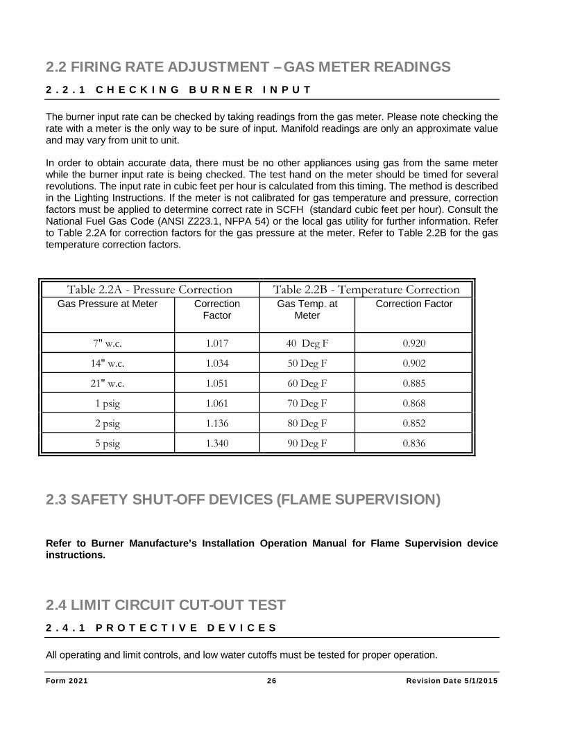
In order to obtain accurate data, there must be no other appliances using gas from the same meter while the burner input rate is being checked. The test hand on the meter should be timed for several revolutions. The input rate in cubic feet per hour is calculated from this timing. The method is described in the Lighting Instructions. If the meter is not calibrated for gas temperature and pressure, correction factors must be applied to determine correct rate in SCFH (standard cubic feet per hour). Consult the National Fuel Gas Code (ANSI Z223.1, NFPA 54) or the local gas utility for further information. Refer to Table 2.2A for correction factors for the gas pressure at the meter. Refer to Table 2.2B for the gas temperature correction factors.
2.3 SAFETY SHUT-OFF DEVICES (FLAME SUPERVISION)
Refer to Burner Manufacture’s Installation Operation Manual for Flame Supervision device instructions.
2.4 LIMIT CIRCUIT CUT-OUT TEST 2 . 4 . 1 P R O T E C T I V E D E V I C E S
All operating and limit controls, and low water cutoffs must be tested for proper operation.
Table 2.2A - Pressure Correction Table 2.2B - Temperature Correction Gas Pressure at Meter Correction
Factor Gas Temp. at
Meter Correction Factor
7" w.c. 1.017 40 Deg F 0.920
14" w.c. 1.034 50 Deg F 0.902
21" w.c. 1.051 60 Deg F 0.885
1 psig 1.061 70 Deg F 0.868
2 psig 1.136 80 Deg F 0.852
5 psig 1.340 90 Deg F 0.836
Form 2021 27 Revision Date 5/1/2015
2 . 4 . 2 O P E R A T I N G C O N T R O L
The pressure in the boiler is regulated by the Boiler Operator. This is a pressure control which senses the steam pressure and turns the boiler on and off accordingly. This control must be operationally tested. Adjust the pressure setting on the control to a pressure less than the boiler pressure (as shown on the boiler pressure gauge). The control should turn the boiler off. Restore the control setting to normal. The boiler should cycle on.
2 . 4 . 3 H I G H L I M I T C O N T R O L
At least one additional pressure control is provided as the high limit control. It is set at a pressure above the operator to act as a back-up should the operator fail. The high limit control must be operationally tested. With the boiler operating, decrease the pressure setting of the limit control below the current pressure of the boiler. The boiler should cycle off. Restore the high limit control setting to normal (pushing the reset button if it is a manual reset type). The boiler should now cycle on.
2 . 4 . 4 L O W W A T E R C U T - O F F ( S )
Most boilers are supplied with a float-operated primary low water cut-off (and pump control or water feeder combination) or electric probe type auxiliary control. These water level controls are intended to sense (and control) the level of the water in the boiler. It operates to shut off the boiler if the water level drops below its sensing level. The low water cut-off controls must be operationally tested by manually lowering the boiler water level (by opening the boiler blowdown valve for probe controls, and by opening the control blowdown valve for float type controls). The boiler should cycle off when the water level drops below the control point of the low water cut-off. When the water level is restored, the boiler should cycle back on. Depress the manual reset button of devices that require manual reset in order to restore the boiler to operation. Carefully read the enclosed literature on the low water cut-off controls, particularly installing, operating and servicing.
2 . 4 . 5 C O M B I N A T I O N L O W W A T E R C U T - O F F & F E E D E R
The low water cut-off/feeder supplied with some boilers serves as a low water cut-off (see above) and also causes make-up water to be added to the boiler, should the water level drop below its control point. This type of control must be operationally tested as described in Section 2.4.1 and also to assure that the make-up water is introduced as needed. Carefully read the enclosed literature on the Low Water Cut-off controls, particularly installing, operating and servicing.
2 . 4 . 6 O T H E R C O N T R O L S
Additional controls, as required for the particular installation, may also be provided. Refer to the literature on these devices included in the Boiler Manual. All such devices must be operationally tested to assure reliable operation of the boiler and system.
Form 2021 28 Revision Date 5/1/2015
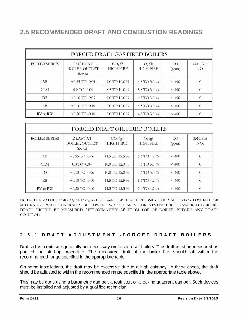
2.5 RECOMMENDED DRAFT AND COMBUSTION READINGS
FORCED DRAFT GAS FIRED BOILERS
BOILER SERIES DRAFT AT BOILER OUTLET
(i.w.c.)
CO2 @ HIGH FIRE
O2 @ HIGH FIRE
CO (ppm)
SMOKE NO.
AB +0.25 TO -0.06 9.0 TO 10.0 % 4.8 TO 3.0 % < 400 0
CLM 0.0 TO -0.04 8.5 TO 10.0 % 5.8 TO 3.0 % < 400 0
DR +0.10 TO -0.06 9.0 TO 10.0 % 4.8 TO 3.0 % < 400 0
EB +0.10 TO -0.10 9.0 TO 10.0 % 4.8 TO 3.0 % < 400 0
RV & RW +0.50 TO -0.10 9.0 TO 10.0 % 4.8 TO 3.0 % < 400 0
FORCED DRAFT OIL FIRED BOILERS
BOILER SERIES DRAFT AT BOILER OUTLET
(i.w.c.)
CO2 @ HIGH FIRE
O2 @ HIGH FIRE
CO (ppm)
SMOKE NO.
AB +0.25 TO -0.06 11.5 TO 12.5 % 5.6 TO 4.2 % < 400 0
CLM 0.0 TO -0.04 10.0 TO 12.0 % 7.6 TO 5.0 % < 400 0
DR +0.10 TO -0.06 10.0 TO 12.0 % 7.6 TO 5.0 % < 400 0
EB +0.10 TO -0.10 11.5 TO 12.5 % 5.6 TO 4.2 % < 400 0
RV & RW +0.50 TO -0.10 11.5 TO 12.5 % 5.6 TO 4.2 % < 400 0
NOTE: THE VALUES FOR CO2 AND O2 ARE SHOWN FOR HIGH FIRE ONLY. THE VALUES FOR LOW FIRE OR MID RANGE WILL GENERALLY BE LOWER, PARTICULARLY FOR ATMOSPHERIC GAS-FIRED BOILERS. DRAFT SHOULD BE MEASURED APPROXIMATELY 24" FROM TOP OF BOILER, BEFORE ANY DRAFT CONTROL.
2 . 5 . 1 D R A F T A D J U S T M E N T - F O R C E D D R A F T B O I L E R S
Draft adjustments are generally not necessary on forced draft boilers. The draft must be measured as part of the start-up procedure. The measured draft at the boiler flue should fall within the recommended range specified in the appropriate table.
On some installations, the draft may be excessive due to a high chimney. In these cases, the draft should be adjusted to within the recommended range specified in the appropriate table above.
This may be done using a barometric damper, a restrictor, or a locking quadrant damper. Such devices must be installed and adjusted by a qualified technician.
Form 2021 29 Revision Date 5/1/2015
2.5.2 COMBUSTION
Refer to the separate burner manual for the procedures for burner adjustments. The burner must be adjusted for a smooth lightoff. Combustion parameters should be within the appropriate range specified in the above table. In no case should the level of CO or the smoke spot reading be allowed to exceed the recommended limit.
2.6 OPERATING INSTRUCTIONS
2 . 6 . 1 F A M I L I A R I Z A T I O N W I T H M A N U A L ( S )
The user of the boiler must familiarize himself with this manual (and the burner manual for those units which are forced draft) to be sure he is prepared to operate and maintain the boiler properly. The operating instructions should be kept adjacent to the boiler.
READ THE MANUAL BEFORE ATTEMPTING A START UP.
2.7 MAINTENANCE SCHEDULE
2 . 7 . 1 P O S T I N G S C H E D U L E
Post a maintenance schedule in accordance with the recommendations in this manual. A copy of a typical schedule is included in this manual.
Form 2021 30 Revision Date 5/1/2015
CARE AND MAINTENANCE STEAM BOILERS
CAUTION: The boiler area should be kept free of combustible materials, gasoline and other flammable
liquids.
The boiler and venting system must be kept free of obstructions of the air louvers and draft hood relief openings.
The following procedures must be conducted as outlined to assure safe operation of the boiler.
All cover plates, enclosures, and guards must be in place at all times, except during maintenance and servicing.
3.1 REQUIRED PRECAUTIONS DURING TEMPORARY USE A boiler is often utilized in new construction to assist in curing of building components or to provide temporary heat for the construction crew or for other purposes during the time the building is under construction. If precautions are not taken during this time to protect the boiler, a great deal of damage can occur before the ultimate owner takes over the building.
It is the mutual responsibility of the installing contractor and the boiler owner to consider the effect of temporary usage on the boiler warranty. The following should be observed so as to assure the longevity of the boiler.
OPERATOR SKILLS/RESPONSIBILITIES During the temporary use period, a single individual must be assigned responsibility for the care and operation of the boiler. This person’s responsibly must include, but not be limited to the following:
Section
3
Form 2021 31 Revision Date 5/1/2015
Knowledge of burner/boiler operations
Possession and understanding of boiler/burner operating instruction manual.
Assurance that the boiler is fed with only treated water al all times and that chemical treatment and blowdown procedures are always followed.
Notification to the manufacturer (or manufacturer’s agent) to provide start-up services if the boiler was purchased with start-up by a factory representative.
Adhere to all of the start-up procedures as noted in the boiler/burner manual.
Consideration of warranty should the boiler be used for temporary heat without adherence to the recommended start-up and operating procedures outlined in the instruction manuals.
3.2 CLEANING THE BOILER AND SYSTEM – NEW SYSTEMS BOIL OUT PROCEDURE The internal surfaces of a newly installed boiler will have oil, grease, or other protective coatings used in manufacturing. Such coatings must be removed since these coatings lower the heat transfer rate and could lead to overheating of a tube and reduce operating efficiency. Before boiling out procedures may begin, the burner must be ready for firing. The operator must be familiar with the procedure outlined in the boiler/burner operating instruction manuals.
In combination with system contamination, bacteria may cause objectionable odors, sometimes resembling natural gas. It is important to keep these fumes from air intake that would distribute them throughout the building. On steam humidification systems this is especially critical. Consult your local water treatment chemist for further information.
CAUTION The boil out procedure outlined must be performed by, or under the direct supervision of, a qualified technician. The chemicals used present a hazard of burns and physical injury if mishandled. Always use suitable facemask, goggles, protective gloves and garments when handling caustic chemicals. Do not permit the chemical to come into contact with skin or clothing. Always follow the safety precautions on the container's label. Add chemicals slowly and in small amounts to prevent excessive heat and agitation. Do not add water to acid. Do not add water to dry chemicals. This will cause splattering and/or explosion and severe risk of personal injury.
Boiling out under pressure is not recommended. If boil out under pressure is required, competent assistance must be provided.
Your water consultant or water treatment company will be able to recommend a cleaning or boil out procedure. In the event that such service is unavailable or as yet not selected, the following may be used.
The boil out of the boiler and system is neither difficult not expensive. The chemicals needed for cleaning are readily available. Tri-sodium phosphate, or sodium hydroxide (lye) are the most commonly used chemicals. Use only one type of solution in the system. The amount of chemical required will very according to conditions, but an amount of one pound of chemical per fifty gallons of water is suggested.
Form 2021 32 Revision Date 5/1/2015
Before introducing the solution into the boiler, an overflow pipe should be attached to the top of the boiler and routed to a safe point of discharge.
Remove all safety valves to ensure that none of the solution will come into contact with the valve seats. Use care in removing and reinstalling valves.
All valves in the piping to and from the system must be closed to prevent the chemical solution from getting into the system.
Gauge glasses must be protected from contact with the boil out chemicals.
Fill the boiler with clean softened water until the water level reaches the upper header. Then add the cleaning solution into the upper header. Add more clean water until the boiler is completely filled. The water used for this initial fill should be at room temperature and must be softened as noted.
After filling, fire the boiler intermittently (at low fire) at a frequency as necessary to hold the boiler solution at boiler point temperature. DO NOT PRODUCE STEAM PRESSURE. Boil the water, supervised at all times, for at least five hours.
After the five-hour boil out, begin to add a small amount of fresh softened water so as to create a slight overflow of the overflow pipe. This will carry out impurities that have accumulated at the water surface. Continue to apply heat and overflow until the water emitted from the overflow pipe clears. Then shut off burner.
Let the boiler cool to 120°F or less. Then drain the boiler. Use caution that the water is discharged with safety.
Remove the inspection/cleanout openings in the boiler upper and lower headers and wash the waterside surfaces thoroughly using high-pressure water stream.
Inspect the boiler’s internal (waterside) surfaces thoroughly after the procedure. If the surfaces are not clean, repeat the boil out.
After boil out, close all openings. Install relief valves, gauge glasses and other components as necessary. Completely fill the boiler with fresh, softened, ambient temperature water. Fire the boiler at low fire until water temperature of at least 180°F is reached. This will drive off dissolved gases.
The boiler is now ready to operate.
3.3 SYSTEM CLEAN OUT
Many boilers have been ruined with system contaminants such as pipe dope, cutting oil, metal shavings or chips, and other debris that are left in the piping. If these contaminants are not removed they will end up in the boiler.
Form 2021 33 Revision Date 5/1/2015
SYSTEM CLEANING PROCEDURE For steam systems, the boiler will need to be connected to the header utilizing steam to purge the piping and thus push the debris out of the system. However, at this time, all condensate must be wasted until it runs clear and water analysis of the condensate indicates that it is free of contaminants. Steam trap strainers must be periodically opened and cleaned of any debris that accumulates.
During this system clean out, the boiler make-up water must be properly softened and treated. At the conclusion of the system clean out, the condensate must be reconnected.
For old or existing steam systems, the installation process may have jarred debris loose. Following the boil out of the new boiler, the condensate should be wasted until it is within proper guidelines. Check all steam trap strainers to assure their cleanliness. Refer to the succeeding section on replacement boiler installations.
3.4 REPLACEMENT BOILER INSTALLATIONS: PROTECTION AGAINST CORROSION & SEDIMENT
CLEAN OR REPLACE ALL SYSTEM PIPING AND HEATING UNITS Arrange for chemical or mechanical cleaning of the entire system. A chemical treatment company should be consulted for the proper means of any chemical cleaning.
Replace any piping considered to be deteriorated beyond safe or cleanable condition.
Flush the system clean, being certain to isolate the boiler.
DO NOT FLUSH THE SYSTEM THROUGH THE BOILER.
NOTE: For some old systems, there is a reluctance to clean the piping because of possible leaks occurring in badly corroded lines. Should the customer refuse cleaning, it is necessary to install filtration equipment. Install either a fibrous filter or a centrifugal filter in the boiler return piping. This will collect and remove sediment from the system. A booster pump may be required to overcome the additional pressure drop introduced in the line by the filter. When filling the system, provide chemical treatment as outlined in Section 3.3.
CAUTION Failure to properly clean the system or to install mechanical sediment removal equipment can result in tube blockage and severe corrosion plus damage to pumps, controls, and air removal devices.
3.5 BOILER WATER TREATMENT PURPOSE OF WATER TREATMENT Water treatment is required for satisfactory operation of the boiler. It must be devised to prevent depositing of scale and corrosion from acids, oxygen and other such harmful elements that may be in the water supply. A qualified water treatment chemist should be consulted and the water systematically treated.
Form 2021 34 Revision Date 5/1/2015
OBJECTIVES The basic objectives of water treatment are:
Prevent the accumulation of scale and deposits in the boiler.
Remove dissolved gases from the water.
Protect the boiler against corrosion.
Maintain the highest possible boiler fuel efficiency.
Decrease the amount of boiler down time from cleaning.
WATER SOFTENER
It is highly recommended that a zeolite water softener be used for all make-up to the boiler. It is intended that this be used in addition to the chemical treatment of the boiler. Water softening removes calcium and magnesium, the primary causes of hard boiler scale.
CONTINUOUS MONITORING REQUIRED Water treatment should be checked and maintained whenever the boiler is operating. The boiler operator should be sure that the boiler is not operating for long periods without proper water treatment.
Water treatment may vary from season to season or over a period of time. Therefore, the water treatment procedure should be checked not less than four times a year and possibly more frequently as the local water conditions may indicate.
3.6 EXTERNAL "FIRE-SIDE" CLEANING
PURPOSE Carbon (soot) is an insulator and is corrosive. The heating surface of a boiler must be kept free from soot accumulation to keep the boiler operating at its highest efficiency and to avoid damage from corrosion.
SOOT REMOVAL If the yearly inspection of the boiler tube surfaces reveals a build-up of soot or rust (usually due to condensation), the tubes should be thoroughly brushed. (Tube cleaning brushes are available from Bryan Steam) To inspect and, if necessary, clean the tube surfaces and flue collector, first remove the tube access panels. Examine the exterior of the tubes for evidence of soot or rust. Using a flashlight, carefully look between the tubes. There should be an unobstructed opening between all tubes, and the top surfaces of the tube must be free from soot accumulation. Also inspect the interior of the flue collector. Brush or vacuum the soot from all surfaces. Be sure to cover the burner nozzle with a protective cover during cleaning to prevent soot from falling into it.
If the buildup of soot is appreciable, the flue gas venting system must be thoroughly inspected internally as well, and cleaned as necessary.
Form 2021 35 Revision Date 5/1/2015
IMPORTANT If either soot or condensation is apparent, a boiler service technician should be consulted. The presence of soot indicates poor combustion and possibly hazardous boiler operation. Failure to do so may result in fire, explosion potential, or asphyxiation. A combustion test and burner adjustments should be undertaken at once.
3.7 SUGGESTED MAINTENANCE SCHEDULE
DAILY Make visual inspection of gauges, monitors, and indicators and record readings in boiler log.
Make visual check of instrument and equipment settings against factory recommended specifications.
Check operation of float type low water cutoffs to ensure control is functioning. The lower piping connections of float type level controls should have a suitable blowdown valve piped into a proper drain. This valve should be opened periodically to allow any sludge accumulated in the control to be flushed out. Consult manufacturer's instructions.
WEEKLY On units equipped with firing rate control, verify it is functioning correctly by adjusting control
and observing if input changes accordingly.
Make visual inspection of pilot flame. Check pilot flame signal strength and main flame operation as specified in burner manual.
Check pilot and main fuel valves for correct operation. Open limit switch - make audible and visual check - check valve position indicators and check fuel meters, if supplied.
Confirm boiler area is free of combustible materials and that there is nothing obstructing air openings, relief openings, etc.
Check combustion safety controls for flame failure and flame signal strength as specified in manufacturer's instructions in the burner manual.
Check all limit controls as specified in Section 2.4 of this manual.
Check float low water cutoff as described above.
MONTHLY Make visual inspection of linkage and proper operation of flue, vent, stack, or outlet dampers.
Check draft as specified in Section 2 of this manual.
Check float low water cutoff as described above.
Check low draft, fan, air pressure and damper position interlocks as specified in burner manual.
Check high and low gas pressure interlocks. Refer to manufacturer's instructions for correct procedure.
Form 2021 36 Revision Date 5/1/2015
Check high and low oil pressure interlocks. Refer to manufacturer's instructions for correct procedure.
ANNUALLY Perform leakage tests on pilot and main gas or main oil fuel valves as specified in
manufacturer's instructions.
Check operating control, high limit, low fire start control, and low water cutoff as specified in manufacturer's instructions.
Check air atomizing interlock, fuel valve interlock switch, purge switch, burner position interlock, and fuel changeover control, as specified in burner manual.
The boiler should be checked at least yearly by the local gas utility company
The flue gas passages and the exterior surfaces of the boiler tubes should be inspected at least annually. Any accumulation of soot or debris should be thoroughly cleaned out.
If the yearly inspection of the boiler tube surfaces reveals a build-up of soot (carbon) or rust, the tubes surfaces should be thoroughly brushed. Failure to do so may result in fire or asphyxiation hazards.
The boiler pressure vessel and piping should be checked annually.
3.8 FLOAT-ACTUATED WATER LEVEL CONTROLS
Inspect float type water level controls for proper operation. Visually inspect sigh glasses for evidence of scale forming residues. Refer to section 3.9 for gauge glass maintenance.
On closed steam heating systems, the float low water cutoff should be blown down by means of opening a blowdown valve on the lower connection of the cutoff once per day.
On humidification or process systems, the blowdown schedule should be based on recommendation from a water treatment and maintenance program specifically designed for the boiler.
At the annual inspection, all float type level controls should be disassembled, cleaned and inspected thoroughly. When re0installed these controls must be give an operational test.
3.9 WATER GAUGE GLASSES
INSTALLATION
Check with the maintenance supervisor and engineer for the proper glass to be used. Compare the box and the glass label or marking to ascertain that the gauge glass ratings or temperature and pressure suitable for use on the boiler. Use new gaskets when replacing glass. The gaskets used should be the same type as those originally supplied with the boiler. Make certain that the gauge glass valves are properly aligned.
All bolts and nuts must be free running and well lubricated, preferably with a graphite type lubricant. Washers under nuts and bolt heads are desirable. DO NOT tighten while equipment is in operation.
Form 2021 37 Revision Date 5/1/2015
MAINTENANCE
Inspect the gauge glass regularly for any signs of clouding or scratching. In new processes, the gauge glass should be inspected daily until the need for replacement becomes apparent. This will help establish the routine inspection cycle.
The gauge glass should be blown down daily so as to remove accumulated sediment from the valves.
INSPECTION
To examine for scratches, shine a bright concentrated light at about a 45 Deg angle. Anything that glistens brightly should be inspected closely. Any scratch which glistens and will catch a fingernail, or crescent-shaped or star-shaped mark is cause for replacement. This is because scratches, corrosion, chips, and surface damage weaken the glass. If inner surface appears cloudy or roughened, and will not respond to cleaning procedures, this is evidence of chemical attack. If severe, this is cause for replacement.
REPLACEMENT OF GLASS
Any glass that has been removed from its mounting in process boilers, regardless of the reason for removal, should be discarded and replaced with a new glass and gaskets. Used glasses may contain hidden damage and represent a safety hazard.
Be sure that the replacement glass is suitable for service conditions.
Protective shields to keep cold air, water, or falling objects from glass must be replaced.
3.10 IDLE BOILER CARE AND LAY-UP
GENERAL
Corrosion damage to boilers is often the result of improper lay-up during non-operating periods. Substantial damage can occur in only a few days if proper precautions are not taken. This damage is irreversible and will reduce boiler reliability, increase maintenance costs and eventually shorten the useful life of the boiler tubes.
Idle boilers are vulnerable to attack when air contacts untreated wet metal surfaces. To prevent corrosion, the boiler metal must be protected by either keeping the surfaces completely dry or excluding air from the boiler. Air exclusion is accomplished by either keeping the boiler completely full of water (short term lay-up) or filling the boiler with nitrogen gas (long-term lay-up). The nitrogen gas prevents air infiltration and does not react with the metal.
In addition to the corrosion damage that occurs, the metal particles that are released will form an insulating scale on the tubes when the boiler is returned to service. These corrosion products will accumulate on critical heat transfer areas of the boiler, increasing the potential for localized corrosion and overheating.
PRE-OPERATIONAL CLEANING AND LAY-UP
In operation, boiler water contains suspended solids that are held in suspension due to water circulation and the action of treatment chemicals. Unless care is exercised when draining the boiler, these suspended solids settle on the tube surfaces and will air dry to an adherent deposit, sometimes requiring chemical cleaning to remove. In addition, these deposits may be misleading regarding the effectiveness of the chemical treatment program.
Form 2021 38 Revision Date 5/1/2015
PRE-SHUTDOWN PRECAUTIONS
For a period of three to seven days prior to shutdown, manual blowdown frequency should be increased. During this period, the lover conductivity limit should be below 3500 micro-mohs per centimeters. The feed of internal treatment must be increased to maintain a specific residual concentration. Continuous blowdown (when used) should be kept to a minimum so the reduction of solids is achieved by the increased manual blowdown.
WASHDOWN As the boiler cannot be washed immediately, the heat in the boiler may cause baking of residual sludge. The boiler should not be drained until cooled enough to prevent this. However, never leave the boiler filled with water for any extended period of time without taking measures to prevent corrosion.
LAY-UP CONSIDERATIONS
There are two basic methods of steam boiler lay-up: Wet lay-up or Dry lay-up. The choice of which method should be used depends on:
The possibility that the boiler may need to be placed operation on short notice.
Disposal of lay-up solution
Freezing potential
Wet Lay-Up is recommended for relatively short outages, such as seasonal lay-up. This method has the advantage of allowing the boiler to be brought on line with short notice. But is can pose problems if there is any likelihood of freezing.
Dry Lay-Up is recommended for longer periods of boiler shutdown or storage. But it is practical only if boiler can be drained hot (120° F to 170° F) or if external drying can be provided.
WET LAY-UP OF STEAM BOILERS – SHORT TERM In the wet lay-up procedure, the boiler is to be filled with chemically treated water and sealed to prevent air in-leakage. Nitrogen gas under slight pressure can also be used to displace air and protect the boiler surfaces from corrosion. The following steps should be taken for wet lay-up of a boiler:
1a. Procedure for Operational Boiler:
At least thirty minutes before the boiler comes off line, add the following chemicals:
Sodium Sulfite – 0.5 lbs per 100 gallons water
Polymeric Sludge Dispersant – 0.1 lbs per 100 gallons water
Caustic Soda – 0.3 lbs per 100 gallons water
1b. Procedure for idle boiler:
if the boiler has never been on line or has been out of service for cleaning, select the highest quality water available to fill the boiler. Steam condensate, softened water, filtered fresh water, and boiler feedwater are generally acceptable for lay-up. Raw city water is not recommended and should not be used.
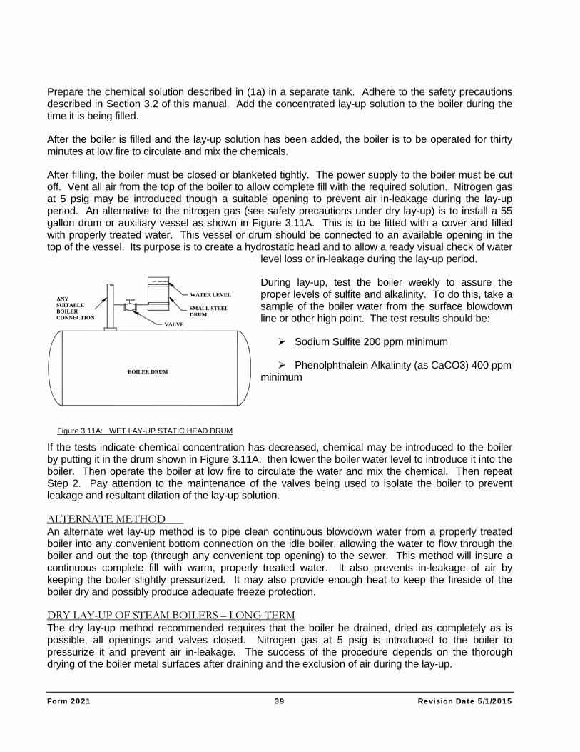
Form 2021 39 Revision Date 5/1/2015
Prepare the chemical solution described in (1a) in a separate tank. Adhere to the safety precautions described in Section 3.2 of this manual. Add the concentrated lay-up solution to the boiler during the time it is being filled.
After the boiler is filled and the lay-up solution has been added, the boiler is to be operated for thirty minutes at low fire to circulate and mix the chemicals.
After filling, the boiler must be closed or blanketed tightly. The power supply to the boiler must be cut off. Vent all air from the top of the boiler to allow complete fill with the required solution. Nitrogen gas at 5 psig may be introduced though a suitable opening to prevent air in-leakage during the lay-up period. An alternative to the nitrogen gas (see safety precautions under dry lay-up) is to install a 55 gallon drum or auxiliary vessel as shown in Figure 3.11A. This is to be fitted with a cover and filled with properly treated water. This vessel or drum should be connected to an available opening in the top of the vessel. Its purpose is to create a hydrostatic head and to allow a ready visual check of water
level loss or in-leakage during the lay-up period.
During lay-up, test the boiler weekly to assure the proper levels of sulfite and alkalinity. To do this, take a sample of the boiler water from the surface blowdown line or other high point. The test results should be:
Sodium Sulfite 200 ppm minimum
Phenolphthalein Alkalinity (as CaCO3) 400 ppm minimum
If the tests indicate chemical concentration has decreased, chemical may be introduced to the boiler by putting it in the drum shown in Figure 3.11A. then lower the boiler water level to introduce it into the boiler. Then operate the boiler at low fire to circulate the water and mix the chemical. Then repeat Step 2. Pay attention to the maintenance of the valves being used to isolate the boiler to prevent leakage and resultant dilation of the lay-up solution.
ALTERNATE METHOD An alternate wet lay-up method is to pipe clean continuous blowdown water from a properly treated boiler into any convenient bottom connection on the idle boiler, allowing the water to flow through the boiler and out the top (through any convenient top opening) to the sewer. This method will insure a continuous complete fill with warm, properly treated water. It also prevents in-leakage of air by keeping the boiler slightly pressurized. It may also provide enough heat to keep the fireside of the boiler dry and possibly produce adequate freeze protection.
DRY LAY-UP OF STEAM BOILERS – LONG TERM
The dry lay-up method recommended requires that the boiler be drained, dried as completely as is possible, all openings and valves closed. Nitrogen gas at 5 psig is introduced to the boiler to pressurize it and prevent air in-leakage. The success of the procedure depends on the thorough drying of the boiler metal surfaces after draining and the exclusion of air during the lay-up.
BOILER DRUM
VALVE
SMALL STEELDRUM
WATER LEVELANYSUITABLEBOILERCONNECTION
Figure 3.11A: WET LAY-UP STATIC HEAD DRUM
Form 2021 40 Revision Date 5/1/2015
CAUTION The use of nitrogen for blanketing is recommended in both the wet and dry lay-up procedures. Even though nitrogen in dilute quantities is non-toxic, it will not support life. Precautions must be taken before entering equipment filled with nitrogen for inspections or any other purposes. These precautions shall be as follows:
disconnection of nitrogen supply line
complete purging and venting of the equipment with fresh air
testing oxygen levels inside before any attempt to enter
all confined entry guidelines applicable to site must be followed
Appropriate caution signs shall be posted around the equipment to alert personal that nitrogen blanketing is in use. A boiler laid up dry must be tagged with information that the unit is not to be operated until the boiler is properly refilled.
Drain the boiler before the steam pressure falls to zero. Then pressurize with 5 psig nitrogen gas through a suitable top opening during draining. The nitrogen pressure is to be maintained through draining and subsequent storage.
An alternate method is to completely dry a clean boil (by blowing hot dry air through the boiler) and then purge the air from the boiler and pressurized with 5 psig nitrogen. Be aware that all metal surfaces that are not completely dry are vulnerable to corrosion, particularly if oxygen is present.
If a boiler has been down for repairs and is to be laid up, it should be operated to pressurize with steam and then drained and pressurized with nitrogen as in Step 1.
All connections must be blanked or tightly closed.
NOTE: Operating boilers must be removed from service to minimize adherence of boiler water suspended solids on boiler metal surfaces. Refer to previous instructions for boiler washdown.
RETURNING IDLE BOILER TO SERVICE After wet lay-up
To start an idle boiler after wet lay-up, use the following procedure:
If the boiler was pressurized with nitrogen, disconnect the nitrogen supply source and vent the boiler.
Using the blowdown valve, drain the boiler partially and make up with feedwater so as to dilute the chemical residuals to operating concentration levels.
After the boiler water concentrations and the water level are returned to proper operating conditions, the boiler can be started in the normal manner.
Form 2021 41 Revision Date 5/1/2015
After dry lay-up
To start an idle boiler after dry lay-up, use the following procedure:
Disconnect the nitrogen supply source and vent the boiler in a safe manner – external to the building and away from air intakes. Then thoroughly purge the boiler of nitrogen with dry air.
The boiler was to have been cleaned before the lay-up procedure. So it is necessary only to fill the boiler with properly treated water. Then proceed with start-up.