Embed Size (px)
Citation preview

RS-2046
Installation and Operating Procedures
For C&D Technologies TRUE Front Access TEL Series Batteries
FOLLOW MANUFACTURER’S PUBLISHED INSTRUCTIONS WHEN
INSTALLING, CHARGING AND SERVICING BATTERIES.
For additional information: www.cdtechno.com Technical-Warranty Assistance, contact:
C&D Technologies, Inc. 1400 Union Meeting Road / PO Box 3053 / Blue Bell, PA 19422-0858
800-543-8630 or 215-619-2700 Fax 215-619-7899
Before handling cells or storing cell for future installation take time to read this manual. It contains information that could avoid irreparable damage to the battery and/or void product warranty.
2 of 12
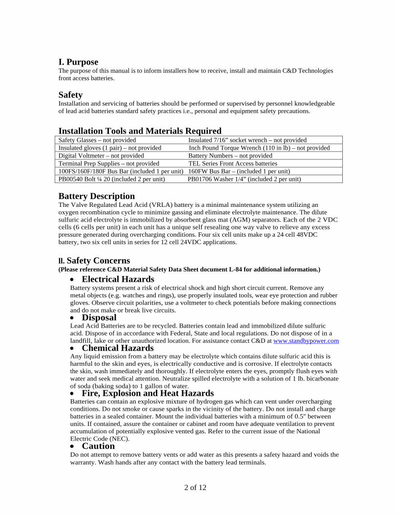
I. Purpose The purpose of this manual is to inform installers how to receive, install and maintain C&D Technologies front access batteries. Safety Installation and servicing of batteries should be performed or supervised by personnel knowledgeable of lead acid batteries standard safety practices i.e., personal and equipment safety precautions. Installation Tools and Materials Required Safety Glasses – not provided Insulated 7/16” socket wrench – not provided Insulated gloves (1 pair) – not provided Inch Pound Torque Wrench (110 in lb) – not provided Digital Voltmeter – not provided Battery Numbers – not provided Terminal Prep Supplies – not provided TEL Series Front Access batteries 100FS/160F/180F Bus Bar (included 1 per unit) 160FW Bus Bar – (included 1 per unit) PB00540 Bolt ¼ 20 (included 2 per unit) PB01706 Washer 1/4” (included 2 per unit) Battery Description The Valve Regulated Lead Acid (VRLA) battery is a minimal maintenance system utilizing an oxygen recombination cycle to minimize gassing and eliminate electrolyte maintenance. The dilute sulfuric acid electrolyte is immobilized by absorbent glass mat (AGM) separators. Each of the 2 VDC cells (6 cells per unit) in each unit has a unique self resealing one way valve to relieve any excess pressure generated during overcharging conditions. Four six cell units make up a 24 cell 48VDC battery, two six cell units in series for 12 cell 24VDC applications. ll. Safety Concerns (Please reference C&D Material Safety Data Sheet document L-84 for additional information.)
• Electrical Hazards Battery systems present a risk of electrical shock and high short circuit current. Remove any metal objects (e.g. watches and rings), use properly insulated tools, wear eye protection and rubber gloves. Observe circuit polarities, use a voltmeter to check potentials before making connections and do not make or break live circuits. • Disposal Lead Acid Batteries are to be recycled. Batteries contain lead and immobilized dilute sulfuric acid. Dispose of in accordance with Federal, State and local regulations. Do not dispose of in a landfill, lake or other unauthorized location. For assistance contact C&D at www.standbypower.com • Chemical Hazards Any liquid emission from a battery may be electrolyte which contains dilute sulfuric acid this is harmful to the skin and eyes, is electrically conductive and is corrosive. If electrolyte contacts the skin, wash immediately and thoroughly. If electrolyte enters the eyes, promptly flush eyes with water and seek medical attention. Neutralize spilled electrolyte with a solution of 1 lb. bicarbonate of soda (baking soda) to 1 gallon of water. • Fire, Explosion and Heat Hazards Batteries can contain an explosive mixture of hydrogen gas which can vent under overcharging conditions. Do not smoke or cause sparks in the vicinity of the battery. Do not install and charge batteries in a sealed container. Mount the individual batteries with a minimum of 0.5'' between units. If contained, assure the container or cabinet and room have adequate ventilation to prevent accumulation of potentially explosive vented gas. Refer to the current issue of the National Electric Code (NEC). • Caution Do not attempt to remove battery vents or add water as this presents a safety hazard and voids the warranty. Wash hands after any contact with the battery lead terminals.
3 of 12
lll. Receiving Instructions Upon receipt, inspect the batteries for physical damage to the containers and terminals. If found, a claim must be filed with the carrier within 10 days. Also check the packing slip to make sure all material has arrived. The batteries are shipped fully charged. Their Open Circuit Voltage (OCV) should not be below 12.48 volts per 12 volt unit. lV. Storage Instructions Store batteries in a clean, dry, cool area away from radiant heat sources. Recharge batteries in storage every 6 months or before their OCV declines to 12.48 VDC. Follow instructions as outlined in section VI Freshening Charge. V. Installation Instructions-Required Installation Tools & Room Equipment At a minimum, the following tools and equipment are required to install VRLA batteries. A digital voltmeter, insulated 7/16” socket wrench, inch pound torque wrench (110 in. lb.), rubber gloves, safety glasses for normal maintenance, full face shield for load testing, optional plastic apron, potable eyewash, spill kit and fire extinguisher (Class C). Optional test equipment, depending on the type of checkout to be performed includes; micro-ohm meter, ohmic test set, 100 amp momentary load test set or system load bank. Typically for Telecom applications, four individual batteries are connected in series to form a higher voltage string of batteries (e.g. 4 each 12 volt batteries connected in series form a 48VDC battery system). Refer to Figure 1 for a 48 VDC series connected battery string using 12 volt front access batteries. Two or more strings may be connected in parallel to increase the total capacity of the system (e.g. two strings of 48 volt 75 ampere-hour batteries connected in parallel make a 48 volts 150 Amp hour battery. Refer to Figure 2 for parallel connected front access batteries. Warranty Date Code C&D’s front access batteries date code is located on the front panel of the battery as a four digit number, MMYY (e.g., 1107 means November 2007). Series -48VDC connection of individual front access batteries Front access batteries are heavy, typically over 100 pounds each. Make sure the proper lifting and moving arrangements to safely handle this weight have been considered before traveling to the site. Note: Disconnect the battery string(s) (A or B) being installed from the DC source by turning the circuit breaker off, if so equipped as noted in Figure 1. Step 1. Beginning with the lowest shelf, string A, place each the individual front access batteries on the shelf (4 per shelf) with approximately 1/2 inch spacing between the individual units. All the batteries should be placed with terminals to the front of the rack / shelf. Remove and save terminal protectors (see Figures 2 & 3). Step 2. C&D recommends, prior to connection of inter-unit bus bars and/or cables, the battery terminals and all contact surfaces should be cleaned, lightly brushed with a brass bristle brush or scotch brite type pad and lightly coated with protective No-Ox-Id terminal grease. Step 3a. Starting at the battery on the right, which is to be the positive (+) output, label it as number 1 and then label the adjacent batteries (right to left) in ascending numerical order 2, 3 & 4 (see Figures 1 , 2 & 3).

4 of 12
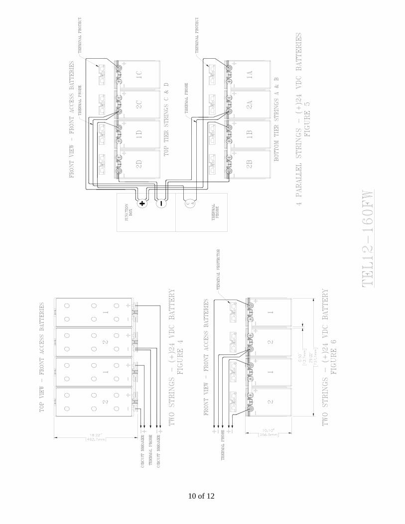
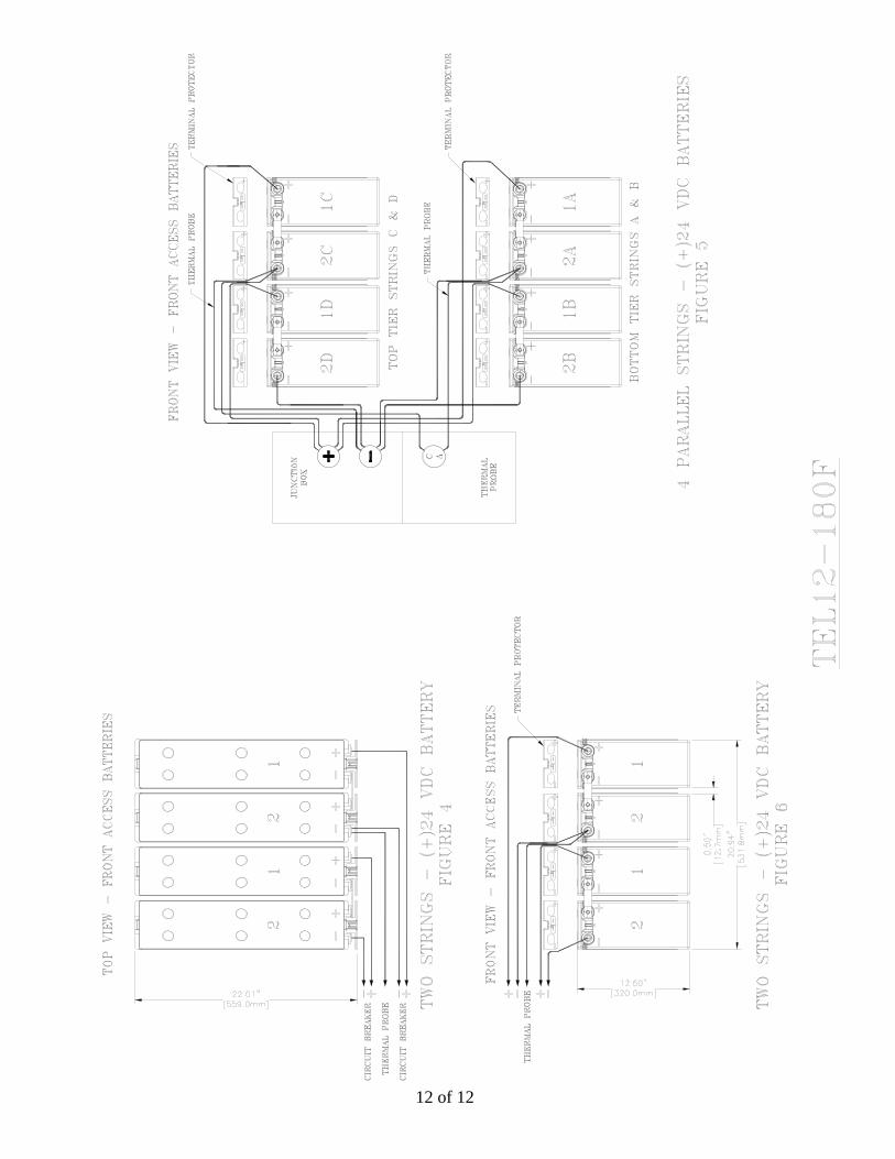
Step 3b. If more than one 48 VDC string is within the enclosure, number the additional batteries the same way. Identify the bottom string as string A with the string above as string B and so on (see Figure 2). Step 4. Properly insulate the String A power supply negative (-) cable lug (cable coming from circuit breaker shown in Figure 1, if a circuit breaker is used) that will eventually be connected to battery 4’s negative (-) terminal. Step 5. Connect String A’s power supply positive (+) cable onto battery number 1’s positive (+) terminal using the provided bolt and washer. Tighten bolt washer assembly hand tight. Step 6. Using the provided bus bar and hardware (bolt and washer), connect between battery 1’s negative (-) terminal to battery 2’s positive (+) terminal. Tighten bolt washer assembly hand tight. Step 7. Using the provided bus bar and hardware (bolt and washer), connect between battery 2’s negative (-) terminal to battery 3’s positive (+) terminal. Before inserting the washer and bolt onto battery 2’s negative (-) terminal, place the power supply’s thermal probe on top of the bus bar (if applicable noted on Figure 1). Once lined up insert the washer and bolt onto battery 2’s negative (-) terminal as well as battery 3’s positive (+) terminal. Tighten bolt washer assembly hand tight. Step 8. Using the provided bus bar and hardware (bolt and washer), connect between battery 3’s negative (-) terminal to battery 4’s positive (+) terminal. DO NOT connect the power supply negative cable to battery 4’s negative (-) terminal. Step 9. Torque all the bolt washer assemblies as per the inch-pound specifications in Table 1 (except the remaining negative (-) power supply cable). Step 10. Carefully remove the earlier applied insulation from the power supply negative (-) cable lug. Do not let the power supply negative (-) cable touch any terminals or any conductive surface. Step 11. Switch the string A circuit breaker to the “on” position, assuming a positive (-) leg circuit breaker as noted in Figure 1 (if applicable). Step 12. To make sure the battery is connected properly, place the voltmeter’s positive (+) probe on battery 4’s positive (+) terminal and the voltmeter’s negative (-) probe to the power supplies negative (-) lug. Check to make sure the polarity is correct (not negative). If the value is negative (-), then the system was not wired properly and must be corrected before it is hooked up to the power supply. Step 13. If step 12’s value was negative (-), do not connect the negative (-) cable lug to battery 4’s negative (-) terminal, again wrap and insulate the enclosures negative (-) cable’s lug. Switch String A circuit breaker to the “off” position (if applicable). Step 14. Connect the power supply negative (-) cable lug to Battery 4’s negative (-) terminal and torque to the specification in table 1. Step 15. Switch string A’s circuit breaker to the “on” position (if applicable). Step 16. Replace the previously removed terminal protectors. Step 17. Repeat the above steps on String B, String C, etc. Series +24VDC connection of individual front access batteries Front access batteries are heavy, typically over 100 pounds each. Make sure the proper lifting and moving arrangements to safely handle this weight have been considered before traveling to the site. Note: Disconnect (isolate) the battery string(s) being installed from the DC source by turning the circuit breaker off, if so equipped as noted in Figure 4.

5 of 12
Step 1. Beginning with the lowest shelf containing string A & B, place each of the individual front access batteries on the shelf (4 per shelf) with approximately 1/2 inch spacing between the individual units. All the batteries should be placed with terminals to the front of the rack / shelf. Remove and save terminal protectors (see Figures 5 & 6). Place a safety shield in the center of the tray between adjacent 24 volt battery strings. Step 2. C&D recommends, prior to connection of inter-unit bus bars and/or cables, the battery terminals and all contact surfaces should be cleaned, lightly brushed with a brass bristle brush or scotch brite type pad and lightly coated with protective No-Ox-Id terminal grease. Step 3a. Starting at the battery on the far right of the tray, which is to be the positive (+) output, label it as number 1 and then label the adjacent battery to the left as battery number two, string A. Repeat the numbering procedure for the adjacent string (next two batteries to the left), string B. (see Figures 4, 5 & 6). Step 3b. If more than two 24 VDC strings is within the enclosure, number these batteries the same way. Identify the bottom tray as string A and B with the strings above as string C and D and so on (see Figure 5). Step 4. Properly insulate the String A power supply negative (-) cable lug that will eventually be connected to battery 2A’s negative (-) terminal. Step 5. Connect String A’s power supply positive (+) cable onto battery number 2A’s positive (+) terminal using the provided bolt and washer for 24 volt DC systems (cable coming from circuit breaker shown in Figure 4). Tighten bolt washer assembly hand tight. Step 6. Using the provided bus bar and hardware (bolt and washer), connect between battery 1A’s negative (-) terminal to battery 2A’s positive (+) terminal. Tighten bolt washer assembly hand tight. Step 7. DO NOT connect the power supply positive cable to battery 2A’s negative (-) terminal. Step 8. Torque all the bolt washer assemblies as per the inch-pound specifications in Table 1 (except the remaining negative (-) power supply cable). Step 9. Carefully remove the earlier applied insulation from the power supply negative (-) cable lug. Do not let the power supply negative (-) cable touch any terminals or any conductive surface. Step 10. Switch the string A circuit breaker to the on position, assuming a positive (+) leg circuit breaker as noted in Figure 4 (if applicable). Step 11. To make sure the battery is connected properly, place the voltmeter’s negative probe on battery 2A’s negative (-) terminal and the voltmeter’s positive probe to the power supplies negative (-) lug. Check to make sure the polarity is correct (not negative). If the value is negative (-), then the system was not wired properly and must be corrected before it is hooked up to the power supply. Step 12. If step 12’s value was positive (+), do not connect the negative (-) cable lug to battery 2A’s negative (-) terminal, again wrap and insulate the enclosures negative (-) cable’s lug. Switch String A circuit breaker to the off position (if applicable). Step 13. If using a thermal probe, before inserting the washer and bolt onto battery 2A’s negative (-) terminal, place the power supply’s thermal probe on top of the negative power supply lug (if applicable noted on Figure 4). Step 14. Connect the power supply negative (-) cable lug to Battery 2A’s negative (-) terminal tightening the bolt washer assembly hand tight. Torque to the specification in table 1. Step 15. Switch string A’s circuit breaker to the on position (if applicable). Step 16. Replace the previously removed terminal protectors.

6 of 12
Step 17. Repeat the above steps on String B, String C, String D, String E, etc.
Parallel Connection of individual strings of batteries C&D recommends each of the individual battery strings be cabled separately to a common junction point or box. Each string should also contain a separate fuse or disconnect switch to facilitate maintenance, see Figure 2 & 5. The parallel connections should be completed only when the charger and load are not connected to the battery output circuit. The battery strings should not be ''daisy chained'' in parallel. Vl. Freshening Charge When the batteries have been in storage or transit for an extended period, over 6 months or if OCV’s are below 12.48 volts or when the number of cells in series is greater than 24, it is recommended the battery system be given a freshening charge at 2.4 volts average per cell for 24 hours. This will assure higher initial performance and will reduce the time period required for the cells to achieve proper voltage balance between the individual units. Normally freshening charges are only necessary at installation. Vll. Float Charging Following the freshening charge (if necessary) the battery system should be placed on “float“ charge at between 2.25 v/c and 2.30 v/c average (approximately 13.5 to 13.8 volts/unit average for 12 volt units at 77°F). Vlll. Periodic Maintenance These VRLA batteries are maintenance free with respect to the electrolyte. However, the charging voltage, temperature, performance and connection resistances must be periodically monitored and any necessary corrective actions taken if irregular values are observed to assure reliable standby power when required. Quarterly Inspection
• Measure and record the system total float charging voltage at the battery terminals • Record the charger on charge output current and voltage • Record the ambient temperature and condition of ventilation equipment • Visually inspect the batteries and rack for; general appearance, cleanliness or any irregularity.
Semiannual Inspection
• Repeat the quarterly checks • Record the on charge voltage of each unit • Optionally perform and record Ohmic checks for trending purposes
Yearly and Initial Inspection
• Repeat the semiannual checks • Inspect all connections to ensure integrity.
Item Bolt Size Wrench Size Initial Torque TEL12-105FS ¼-20 ¾ inch long 7/16 110 inch pounds TEL12-160FW ¼-20 ½ inch long 7/16 110 inch pounds TEL12-160F ¼-20 ½ inch long 7/16 110 inch pounds TEL12-180F ¼-20 ½ inch long 7/16 110 inch pounds
Table 1

7 of 12

8 of 12

9 of 12
10 of 12

11 of 12
12 of 12