Embed Size (px)
Citation preview

BEKOMAT® 8 ANSIBEKOMAT® 9 ANSI
EN - English
01-3
049
Condensate drain
Installation and operating manual

Installation and operating manual EN
2 BEKOMAT® 8/9 ANSI

EN Installation and operating manual
BEKOMAT® 8/9 ANSI 3
Contents
1. Safety information .......................................................................................................................................... 4
1.1. Pictograms and symbols .......................................................................................................................... 41.1.1. In this documentation ........................................................................................................................................................41.1.2. On the device .......................................................................................................................................................................4
1.2. Signal words according to ISO 3864 and ANSI Z.535 ................................................................................ 41.3. General safety instructions ..................................................................................................................... 51.4. Transport and storage ............................................................................................................................. 71.5. Intended use ........................................................................................................................................... 81.6. Warranty and liability ............................................................................................................................. 8
2. Product information ....................................................................................................................................... 9
2.1. Type plate ............................................................................................................................................... 92.2. Product overview and description ......................................................................................................... 102.3. Function ............................................................................................................................................... 11
2.3.1. Alarm mode ....................................................................................................................................................................... 11
2.4. Dimensions ........................................................................................................................................... 122.4.1. BEKOMAT® 8 ..................................................................................................................................................................... 122.4.2. BEKOMAT® 9 ..................................................................................................................................................................... 12
2.5. Technical data ....................................................................................................................................... 132.5.1. Performance data ............................................................................................................................................................. 13
3. Installation ................................................................................................................................................... 14
3.1. Warning ................................................................................................................................................ 143.2. Installation ........................................................................................................................................... 15
4. Electrical installation .................................................................................................................................... 16
4.1. Installation instructions ........................................................................................................................ 164.2. Electrical connections ........................................................................................................................... 16
5. Operation ..................................................................................................................................................... 18
5.1. Function test ........................................................................................................................................ 19
6. Maintenance and servicing............................................................................................................................ 20
6.1. Maintenance schedule .......................................................................................................................... 206.2. Cleaning ............................................................................................................................................... 216.3. Spare parts ........................................................................................................................................... 226.4. Accessories ........................................................................................................................................... 22
7. Troubleshooting and repair ........................................................................................................................... 23
8. Declaration of Conformity ............................................................................................................................ 24

Installation and operating manual EN
4 BEKOMAT® 8/9 ANSI
1. Safety information
1.1. Pictograms and symbols
1.1.1. In this documentation
General instructions
Observe installation and operating instructions
General hazard symbol (danger, warning, caution)
General hazard symbol (danger, warning, caution) relating to mains voltage and powered machine parts
1.1.2. On the device
Observe installation and operating instructions(on type plate)
1.2. Signal words according to ISO 3864 and ANSI Z.535
DANGER Imminent dangerConsequences of non-compliance: serious or even fatal injury
WARNING Potential dangerConsequences of non-compliance: serious or even fatal injury
CAUTION Imminent dangerConsequences of non-compliance: injury and/or damage to property
NOTICE Additional notes, tips and hintsConsequences of non-compliance: inefficient operation, extra maintenance; no risk to persons

EN Installation and operating manual
BEKOMAT® 8/9 ANSI 5
1.3. General safety instructions
DANGER Insufficient qualification
Improper handling and operation of the device might result in serious or even fatal injury, and/or serious damage to property.
• All tasks described in this installation and operating manual must be performed by specialist technical personnel1 who meet the criteria outlined below:
• Before carrying out any work with or on the device, all specialist technical personnel¹ must have read and understood the contents of this installation and operating manual.
DANGER Escaping compressed gas
Risk of serious or even fatal injury from suddenly released compressed gas or condensate at bursting and/or unsecured device components.
• Before carrying out any assembly, installation or maintenance work, depressurise the system. All electrical work must be carried out by authorised specialist technical personnel1.
• Use only pressure-resistant installation materials and suitable tools that are in proper working order.• Before pressurising the system, check all unit parts and repair them, if necessary. Open valves slowly
to prevent pressure blows during operation. • Make sure that no persons can be injured or objects can be damaged by condensate or escaping
compressed gas.• Protect the device parts against vibration and impact.• Perform a leakage test.
DANGER Mains voltage
Risk of serious or even fatal injury from electric shock when coming into contact with non-insulated, powered components.
• For the electrical installation of the device, adhere to all applicable regulations (e.g. VDE 0100 / IEC 60364).
• Before carrying out any maintenance work, de-energize the system. • All electrical work must be carried out by authorised specialist technical personnel1.
WARNING Operation of device outside limit range
If the specified limits are exceeded, there is a risk of device malfunction, potentially resulting in injury and/or damage to property.
• The device must only be operated for the intended purpose and within the permissible limits specified on the type plate and in the technical data.
• Strictly adhere to the prescribed operating times and maintenance intervals.
1 Specialist technical personnelSpecialist technical personnel are persons who, due to their professional qualification and knowledge in the field of measuring, control and pneumatic technology, and their knowledge of the applicable statutory regulations, guidelines and standards are in a position to foresee potential dangers in relation to the use of the device and are qualified to perform the tasks described in this manual. Special operating conditions (e.g. aggressive media) require additional knowledge. It is the responsibility of the device owner to ensure that the instructions in this manual are adhered to.

Installation and operating manual EN
6 BEKOMAT® 8/9 ANSI
NOTICE Warranty and liability for defects
Claims made with reference to warranty and liability for defects shall only be deemed valid, if the following instructions are strictly adhered to:• Do not make any modifications to the device!• Use only original spare parts and accessories!• Strictly observe the installation and operating instructions!• Use the device only for the intended purpose.For more information on warranty and liability, see 1.6 auf Seite 8.
NOTICE Installation and operating manual
First make sure that the installation and operating manual actually refers to your device type. This document contains important information and instructions for the safe operation of the device. Before carrying out any work with or on the device, all specialist technical personnel¹ must have read this manual. A copy of this installation and operating manual must be kept near the device where it is at all times accessible to staff. In addition to the instructions in this document, always comply with the statutory regulations for machine operation, accident prevention and safety. This also applies to the use of accessories and spare parts.
1 Specialist technical personnelSpecialist technical personnel are persons who, due to their professional qualification and knowledge in the field of measuring, control and pneumatic technology, and their knowledge of the applicable statutory regulations, guidelines and standards are in a position to foresee potential dangers in relation to the use of the device and are qualified to perform the tasks described in this manual. Special operating conditions (e.g. aggressive media) require additional knowledge. It is the responsibility of the device owner to ensure that the instructions in this manual are adhered to.

EN Installation and operating manual
BEKOMAT® 8/9 ANSI 7
1.4. Transport and storage
Despite our best efforts regarding packaging, etc., the device might be damaged during transport. Upon delivery, please remove all packaging material and inspect the device for visible damage. If you detect such damage, immediately notify the carrier company and BEKO TECHNOLOGIES GMBH or one of its agents.
CAUTION Damage caused during transport or storage
Incorrect transport or storage, or the use of unsuitable lifting equipment might cause damage to the device.
• The device must only be transported and stored by authorised and suitably trained technical personnel.
• If you detect any damage, do not start the device.• Always adhere to the specified transport and storage temperatures.• Protect the device against direct sunlight and heat radiation.
The device must be stored in the original packaging. Seal the packaging and store it in a dry and frost-free room. Ensure that the storage temperature does not exceed the limits specified on the type plate.
Even when packaged, take suitable measures to protect the device against the elements.
While in storage, secure the device so that it cannot topple over or fall, and protect it against vibration.
NOTICE Recycling of packaging material
• The packaging material is recyclable. Dispose of the packaging material according to the applicable statutory regulations.
Installation and operating manual EN
8 BEKOMAT® 8/9 ANSI
1.5. Intended use
The BEKOMAT® is an electronically level-controlled condensate drain for compressed air systems. It is able to drain condensate from the plant components at operating pressure and with virtually no compressed air loss.
• The device must only be operated when equipped with original spare parts and accessories.• Do not install the BEKOMAT® 8/9 in areas with a potentially explosive atmosphere.• Permissible media: condensate, oil-contaminated or oil-free
Operate the BEKOMAT® only for the intended purpose and within the limit ranges specified in the technical data. Do not operate the device with any media (fluids, gas/vapour mixtures) other than those listed above. Any other use of the device is deemed improper and poses a risk to persons, property and the environment.
1.6. Warranty and liability
All warranty shall be voided, if the BEKOMAT® is used improperly, for a purpose other than the intended or is operated outside the limits specified in the technical data. In such cases, the manufacturer shall also reject any liability for damages. Improper operation includes:
• Incorrect installation, commissioning or operation; insufficient maintenance• Operation with defective components• Non-compliance with the instructions in this document, in particular the safety instructions• Modification of the device• Use of third-party spare parts that have not been approved by the manufacturer

EN Installation and operating manual
BEKOMAT® 8/9 ANSI 9
2. Product information
2.1. Type plate
The type plate is attached to the device housing. It contains all key data of the BEKOMAT®. Please have these details to hand when contacting the manufacturer or supplier.
Hersteller: BEKO TECHNOLOGIES GmbHBaujahr: 2016zul. Betriebsdruck: 0,5 ... 10 barzul. Betriebstemp.: +1°C/+60°C Medium: Druckluft / KondensatInhalt: 19,5 lBehälternr. 12345678 B
eisp
iel /
Exa
mpl
e
Designation Description
Hersteller: BEKO TECHNOLOGIES GmbH Name of manufacturer
Baujahr: 2016 Year of manufacture
zul. Betriebsdruck: 0.5 ... 10 bar Max. permissible operating pressure
zul. Betriebstemp.: +1°C/+60°C Max. permissible operating temperature
Medium: Compressed air / condensate Permissible media
Inhalt: 19.5 l Capacity of container
Behälternr. Container number
NOTICE Handling of type plate
Do not remove or cover the type plate, and protect it against damage.

Installation and operating manual EN
10 BEKOMAT® 8/9 ANSI
2.2. Product overview and description
17
2
3 4
5
6
9
10
8
11
1 Condensate inlet 7 Manual drain
2 Venting line 8 Valve LED
3 Control elements / electrical control 9 Alarm LED
4 Solenoid valve 10 Power LED
5 Condensate discharge/solenoid valve 11 Test button
6 Type plate
NOTICE No permanent drainage
Do not use the test button for permanent drainage!

EN Installation and operating manual
BEKOMAT® 8/9 ANSI 11
2.3. Function
Discharge
The condensate enters the container (1) through the condensate inlet. The container can be filled to the limit, as the pressure is equalised through the venting line (2). The capacitive dual sensor (3) constantly monitors the filling level in the container.
As soon as the container is full, the sensor sends a signal to the electric control (4). The electric control actuates the solenoid valve (5), and a large outlet diaphragm is opened to allow the condensate to be discharged.
While the container is under system pressure (min. 0.5 bar), all condensate in the container is drained off through the condensate drain (6). The sensor measures the discharge rate, which is used to control the maximum valve opening time.
Should the condensate fail to drain off, the valve is closed after 2.5 seconds and automatically opened again after 2 seconds. This procedure is repeated for 1 minute as the control system tries to resolve the problem.
2.3.1. Alarm mode
The BEKOMAT® is continuously monitored by electronic and sensory devices. If a fault or malfunction occurs, the BEKOMAT®
is automatically switched to alarm mode (e.g. due to blocked condensate discharge, or overload). In alarm mode, the solenoid valve is automatically opened, starting in cycle mode in order to eliminate the problem. If the problem persists for more than one minute, the red alarm LED flashes and the optocoupler output is switched. The valve is then repeatedly opened every four minutes for 7.5 seconds, until the problem is resolved automatically or by servicing the device. After the problem has been resolved, the BEKOMAT® automatically switches to normal operating mode.
1 min
4 minVentil
Alarm-LED7,5 s 7,5 s 7,5 s
4 min 4 min3 min
12 3
4 5
6
Installation and operating manual EN
12 BEKOMAT® 8/9 ANSI
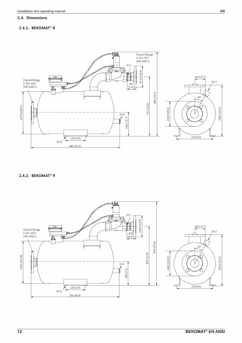
2.4. Dimensions
2.4.1. BEKOMAT® 8
486 (19.1)
Ø27
3 (Ø
10.7
)
331
(13.
0) 485
(19.
1)
Ø 1
15 (4
.5)
146,
5 (5
.7)
334,
5 (1
3.2)
150 (5.9)
G1-i
~64(2.5)
Flansch/flangeC 50 x 60,3DIN 1092-1
Flansch/flangeC 25 x 33,7DIN 1092-1
30°
68,3 (2.7)
Ø 11
Ø16
5 (Ø
6.5)
G¾-i
G¾-i
237(9.3)
2.4.2. BEKOMAT® 9
734 (28.9)
Ø32
5 (Ø
12.8
)
455
(17.
9) 645
(25.
4)
Ø16
5 (Ø
6.5
)
180
(7.1
) 393,
5 (1
5.5)
150 (5.9)
G2-i
~106(4.2)
Flansch/flangeC 50 x 60,3DIN 1092-1
25°
68,3 (2.7)
Ø 11
Ø16
5 (Ø
6.5
)
G¾-i
G¾-i
237(9.3)

EN Installation and operating manual
BEKOMAT® 8/9 ANSI 13
2.5. Technical data
General data BM 08 BM 09
Min./max. storage/transport temperature +1 ... +60 °C
Min./max. medium/ambient temperature +1 ... +60 °C
Min./max. operating pressure 0.5 ... 10 bar 0.5 ... 4 bar
Condensate inlet C50 x 60.3 DIN 1092-1 flange
Condensate discharge G1 G2
Venting connection G¾
Manual drain G¾
Condensate oil-contaminated or oil-free condensate
Weight 28.0 kg (empty) 38.0 kg (empty)
Container capacity 19.5 l 44 l
Discharge volume per cycle 15 l 36 l
MaterialsHousing: Stainless steel (1.4541)
Valve: Brass
Electrical data BM 08 BM 09
Operating voltage230/200/110/100/48/24 VAC ±10% , 50 - 60 Hz ; 24 VDC
(see type plate)
Power consumption < 10 VA
Recommended wire cross-section Ø 5.8 ... 11 mm; 3 x 0.75 mm²
Fuse (medium time lag) 0.5 A
Alarm relay: Contact ratingP < 125 W/VA ; I = 0.1... 0.5 A U < 250 VAC ; U > 12 VDC
2.5.1. Performance data
BM 08 BM 09
BetriebsdruckOperating pressure
Jahres-NennleistungCondensatedischarge capacity
Maximalleistung(kurzzeitig)Short-term max.condensate discharge
Jahres-NennleistungCondensatedischarge capacity
Maximalleistung(kurzzeitig)Short-term max.condensate discharge
[bar] [m3/a] [l/h] [m3/a] [l/h]
0.5 9,360 1,400 24,000 3,600
1.0 10,700 2,250 29,200 6,130
2.0 11,100 3,330 29,600 8,880
4.0 11,400 4,800 30,000 12,600
6.0 12,700 5,580 -- --
8.0 13,700 6,000 -- --
10.0 14,400 6,300 -- --

Installation and operating manual EN
14 BEKOMAT® 8/9 ANSI
3. Installation
3.1. Warning
DANGER Insufficient qualification, explosion
Improper handling and operation of the device can result in serious or even fatal injury, and/or damage to property.
• All tasks described in this installation and operating manual must be performed by specialist technical personnel1 who meet the criteria outlined below:
• Before carrying out any work with or on the device, all specialist technical personnel¹ must have read and understood the contents of this installation and operating manual.
DANGER Escaping compressed gas
Incorrect installation and device parts that are not properly secured and protected can cause serious or even fatal injury.
• Before carrying out any assembly or installation work, depressurise the system.• Use only pressure-resistant installation materials and suitable tools that are in proper working order.• Before pressurising the system, check all unit parts and repair them, if necessary. Open valves slowly
to prevent pressure blows during operation. • Make sure that no persons can be injured or objects can be damaged by condensate or escaping
compressed gas.• Protect the device parts against vibration and impact.• Perform a leakage test.
1 Specialist technical personnelSpecialist technical personnel are persons who, due to their professional qualification and knowledge in the field of measuring, control and pneumatic technology, and their knowledge of the applicable statutory regulations, guidelines and standards are in a position to foresee potential dangers in relation to the use of the device and are qualified to perform the tasks described in this manual. Special operating conditions (e.g. aggressive media) require additional knowledge. It is the responsibility of the device owner to ensure that the instructions in this manual are adhered to.

EN Installation and operating manual
BEKOMAT® 8/9 ANSI 15
3.2. Installation
The diagrams below show examples of BEKOMAT® 8/9 installation options.
NOTICE Installation instructions• Install a separate BEKOMAT® at each point where condensate might be produced.• Do not use cone-shaped fittings.• Keep the pipes as short as possible.• Do not install filters/dirt traps in the condensate inlet.• Only install ball valves in the condensate inlet line.• The venting line must be installed above the highest possible condensate level.• Observe the minimum installation heights.
Installation of BEKOMAT® 8/9
Venting line A: Lines ≥ ¾" must be equipped with ball valve
Condensate inlet B: Pipes ≥ 2" (DN 50) must be installed with flange and ball valve: • short inlet pipe!• Condensate inlet slope >1%!• No filter in condensate inlet!
Condensate discharge C:Install pipe ≥1" (for BEKOMAT® 9: ≥ 2"):• Do not feed to a manifold!• Max. incline 5 m! • If the pipe is installed at an incline, the minimum
operating pressure is increased by 0.1 bar per metre!
For maintenance:
Manual drain D:• Lines ≥ ¾" must be equipped with ball valve
Bypass line E:• Lines ≥ 1" must be equipped with ball valve
B
A
C
D
E

Installation and operating manual EN
16 BEKOMAT® 8/9 ANSI
4. Electrical installation
4.1. Installation instructions
DANGER Insufficient qualification
Improper handling and operation of the device might result in serious or even fatal injury, and/or serious damage to property.
• All tasks described in this installation and operating manual must be performed by specialist technical personnel1 who meet the criteria outlined below:
• Before carrying out any work with or on the device, all specialist technical personnel¹ must have read and understood the contents of this installation and operating manual.
DANGER Mains voltage
Risk of serious or even fatal injury from electric shock when coming into contact with non-insulated, powered components.
• For the electrical installation of the device, adhere to all applicable regulations (e.g. VDE 0100 / IEC 60364).
• Before carrying out any maintenance work, de-energize the system. • All electrical work must be carried out by authorised specialist technical personnel1.
1 Specialist technical personnelSpecialist technical personnel are persons who, due to their professional qualification and knowledge in the field of measuring, control and pneumatic technology, and their knowledge of the applicable statutory regulations, guidelines and standards are in a position to foresee potential dangers in relation to the use of the device and are qualified to perform the tasks described in this manual. Special operating conditions (e.g. aggressive media) require additional knowledge. In addition, observe the requirements for "qualified persons" as laid down in the Technical Rules on Operational Safety (TRBS). It is the responsibility of the device owner to ensure that the instructions in this manual are adhered to.
4.2. Electrical connections
Opening top part of cover: • Loosen the 4 screws• Remove the lid
For power cable connection (or alarm signal line): Disconnect the cable terminals at the bottom
1
PowerAlarm

EN Installation and operating manual
BEKOMAT® 8/9 ANSI 17
1.D
1.1
L1
N
PE
PE
PE
N
V1
N.C
COM
N.O
2.0
2.1
3.0
3.1
3.2
NetzteilPower supply Netzanschluss
Power
MagnetventilSolenoid valve
AlarmkontaktAlarm contact
Gehäuse Housing
VentilsteuerungValve control
ZeitauswertungTime analysis
Sensor-KreisSensor loop
Oscillator
AlarmkontrolleAlarm monitoring
Sensor
MAX
MIN
Connecting power cable: • Push the cable through the cable screw and connect it to terminals L1, N, PE
Alarm signal line: The device is equipped with a floating alarm relay (changeover) for the transfer of alarm signals in the event of a fault:• push the cable through the second cable screw and connect it N.C. – COM: Contact is made in the event of a fault or power failure (fail-safe contact)N.O. – COM: Contact is made during normal operation
• Tighten cable screw(s)• Mount the top part of the cover and tighten the screws• Mount the housing cover and tighten the screws

Installation and operating manual EN
18 BEKOMAT® 8/9 ANSI
5. OperationThe operating state of the BEKOMAT® is indicated as follows.
Normal status:
Normal operation:• Green "POWER" LED is lit: Power OK, BEKOMAT® in operation
Error status:
• Yellow "VALVE" LED is lit:
Max.fillinglevelreached Valve opens, condensate is discharged
The valve opening time is sensor-controlled (based on the actual discharge rate)
After condensate has been discharged:- BEKOMAT® is empty- Valve closes- No unnecessary compressed air loss
Alarm status:
ALARM:
• Insufficientpressuretoopenvalve
• Too much condensate being produced see "Technical data"
• Inlet or drain pipe blocked or closed
• Excessive dirt (valve blocked)
• Solenoid valve defective see "Maintenance"
• Piping frozen
• Incorrect installation see "Installation"
The alarm is automatically reset when the problem that has caused it is resolved.

EN Installation and operating manual
BEKOMAT® 8/9 ANSI 19
5.1. Function test
Testing normal functionTo test the solenoid valve, press the test button briefly (for approx. 2 seconds). Red "ALARM" LED flashes, yellow "VALVE" led is lit Valve to condensate discharge is opened
Testing alarm functionTo test the solenoid valve alarm function, close the condensate inlet and press and hold the test button for approx. 1 minute. Alarm relay switches over
Release TEST button BEKOMAT® returns to normal mode operation
• Condensate inlet is again open!• Min. operating pressure 0.5 bar!
Installation and operating manual EN
20 BEKOMAT® 8/9 ANSI
6. Maintenance and servicing
DANGER Insufficient qualification
Improper handling and operation of the device might result in serious or even fatal injury, and/or serious damage to property.
• All maintenance tasks must be performed by service personnel of BEKO TECHNOLOGIES GmbH or an authorised BEKO partner.
Recommended interval: 1x per yearWearing parts kit to be used:
BEKOMAT® 8 2000450BEKOMAT® 9 4005382
Preparation:• Close inlet• Press TEST button until BEKOMAT® is depressurised • Disconnect BEKOMAT® from power supply
6.1. Maintenance schedule
Maintenance Interval
Function test• Press the TEST button• Visual inspection
daily
Maintenance• Replace wearing parts (kit)• Perform leakage test• Perform function test• Check adhesive label and replace, if necessary• Check valve core length• Check cable connections• Clean
annually
Function test: We strongly recommend performing a daily function test of the BEKOMAT®.
• To test the solenoid valve, press the test button briefly (for approx. 2 seconds). The BEKOMAT® starts a manual drain cycle.
• To test the alarm function, close the condensate inlet and press and hold the test button for approx. 1 minute. The BEKOMAT® starts a manual drain cycle and triggers an alarm.
During this test, large volumes of compressed gas might enter the condensate collection line.
Maintenance:For more information regarding the maintenance of the device, contact the manufacturer.

EN Installation and operating manual
BEKOMAT® 8/9 ANSI 21
6.2. Cleaning
To clean the BEKOMAT®, use a damp (but not wet) cotton cloth or disposable tissue and a mild conventional detergent.
Spray a little detergent onto the clean cotton cloth or tissue and carefully wipe the component. Dry the device with a clean cloth or let it dry at room temperature. Observe all hygiene instructions applicable on the site.
NOTICE Damage caused by improper cleaning
Cleaning with a wet cloth, pointed implement or aggressive detergent can cause damage to the device components and integrated electronic components.
• Never clean the device with a wet cloth.• Do not use aggressive detergents.• Do not clean or operate the device with hard or pointed implements.
Cleaning
A. Cleaning container:Do not actuate the test switch, but: • Close inlet• Carefully open manual drain at
container • Residual pressure flushes container
B. Cleaning sensor tube:• Remove the flange at the top of the
container (loosen hose connector, cable plug and flange screws; lift flange with electronic assembly and sensor tube from the container)
• Clean only the outside of the sensor tube, not the inside
• Reassemble and install the flange
C. Cleaning valve:Do not attempt to open the screws marked in colour! The coloured screws are factory-set and must not be interfered with!
BC
A

Installation and operating manual EN
22 BEKOMAT® 8/9 ANSI
6.3. Spare parts
Wearing parts kit 1x Solenoid valve, complete 2x Hose connector 1x Hose piece
BEKOMAT® 8230 VAC 2000450
BEKOMAT® 9230 VAC 4005382
Other voltage ratings: on request
Gasket kit 8x gaskets for sensor 1x gasket for manual drain BEKOMAT® 8/9
2000683
PCB 230 VAC 1x PCB 230 VAC
BEKOMAT® 82000763
BEKOMAT® 94005381
PBC 110 VAC 1x PCB 110 VAC
BEKOMAT® 82002768
BEKOMAT® 94013115
PCB 24 VDC1x PCB 24 VDC
BEKOMAT® 82000231
BEKOMAT® 92001970
6.4. Accessories
Table of available accessories
Picture Description Order number*
Trace heating systemBEKOMAT® 8/92801233
Heater tape extension 3mBEKOMAT® 8/92801232

EN Installation and operating manual
BEKOMAT® 8/9 ANSI 23
7. Troubleshooting and repairIn the event of a malfunction of the device, return it to the manufacturer for repair. Clean the device carefully and pack it so that it is protected against impact. Return the device to the manufacturer, enclosing a return declaration with a detailed description of the fault/malfunction. If your device has come into contact with a hazardous substance, also enclose a declaration of decontamination. The relevant templates can be downloaded from our homepage at www.beko-technologies.com. If your device arrives at our service workshop without a declaration of decontamination, and should our personnel be concerned about any media with which it might have come into contact, we will contact you. A repair will only be performed after we have received the relevant declaration of decontamination. If the device has been exposed to a hazardous substance, take all necessary safety precautions when cleaning it!

Installation and operating manual EN
24 BEKOMAT® 8/9 ANSI
8. Declaration of Conformity

EN Installation and operating manual
BEKOMAT® 8/9 ANSI 25
BEKO TECHNOLOGIES GMBH Im Taubental 7 41468 Neuss, GERMANY Phone: +49 2131 988-0 www.beko-technologies.de
EC / EU Declaration of Conformity We herewith declare that products named below conform to the applicable directives and technical standards. This declaration applies exclusively to the products as delivered. It does not cover components added at a later stage or modifications made after delivery. Product designation: Condensate drain Type: BEKOMAT 8, BEKOMAT 9 Voltage options: 24VAC/ 100VAC/ 110VAC
200VAC, 230VAC: Pressure options: 0,5 - 10 bar (g) (only BEKOMAT 8)
0,5 - 4 bar (g) (only BEKOMAT 9) Product description and function: Condensate drain for the electronically level-controlled
discharge of condensate in the compressed-air system. Pressure Equipment Directive PED 97/23/EC Applied conformity assessment procedure: Module A Internal production control, Category I Low-Voltage Directive 2006/95/EC Applied standards: EN 61010-1 2010
Section 1-14, 16, 17 Annex A-D, F, G. I-, ZA Year of CE-labeling 2003 The devices with working voltage of 24VDC and 24VAC are not in the scope of the Low-Voltage Directive. EMC-Directive 2004/108/EC Applied standards: EN 55011: 2009, group 1, class B; EN 61326: 2013 RoHS II Directive 2011/65/EU The products meet the requirements laid down in European Directive 2011/65/EU concerning the restriction of the use of certain hazardous substances in electrical and electronic devices. Neuss, 21/09/2015 BEKO TECHNOLOGIES GMBH ppa Christian Riedel Head of Quality Management

Installation and operating manual EN
26 BEKOMAT® 8/9 ANSI
EN Installation and operating manual
BEKOMAT® 8/9 ANSI 27

Translation of the original instructions. Original instructions are in German. Subject to technical changes without prior notice. Errors and omis-sions excepted.bekomat_8_9_ansi_manual_en_01-3049_1610_v00
HeadquartersGermanyBEKO TECHNOLOGIES GMBHIm Taubental 7 D - 41468 NeussPhone +49 2131 988 0 [email protected]
United KingdomBEKO TECHNOLOGIES LTD.Unit 11-12 Moons ParkBurnt Meadow RoadNorth Moons MoatRedditch, Worcs, B98 9PAPhone +44 1527 575 [email protected]
FranceBEKO TECHNOLOGIES S.à.r.l.Zone Industrielle1 Rue des Frères Rémy F - 57200 SarregueminesPhone +33 387 283 [email protected]
BeneluxBEKO TECHNOLOGIES B.V.Veenen 12NL - 4703 RB RoosendaalPhone +31 165 320 [email protected]
中华人民共和国 / ChinaBEKO TECHNOLOGIES (Shanghai) Co. Ltd. Rm. 606 Tomson Commercial Building710 Dongfang Rd.Pudong Shanghai ChinaP.C. 200122Phone +86 21 508 158 [email protected]
Czech RepublicBEKO TECHNOLOGIES s.r.o. Na Pankraci 58CZ - 140 00 Praha 4Phone +420 24 14 14 717 [email protected]
SpainBEKO Tecnológica España S.L. Torruella i Urpina 37-42, nave 6E - 08758 CervellóPhone +34 93 632 76 [email protected]
中華人民共和國香港特別行政區 /
Hong Kong SAR of ChinaBEKO TECHNOLOGIES LIMITED Unit 1010 Miramar Tower 132 Nathan Rd.Tsim Sha Tsui Kowloon Hong KongPhone +852 5578 6681 (Hong Kong)Phone +86 147 1537 0081 (China)[email protected]
IndiaBEKO COMPRESSED AIR TECHNOLOGIES Pvt. Ltd.Plot No.43/1 CIEEP Gandhi NagarBalanagar Hyderabad IN - 500 037Phone +91 40 [email protected]
ItalyBEKO TECHNOLOGIES S.r.lVia Peano 86/88I - 10040 Leinì (TO)Phone +39 011 4500 [email protected]
日本 / JapanBEKO TECHNOLOGIES K.KKEIHIN THINK Building 8 Floor1-1 Minamiwatarida-machiKawasaki-ku, Kawasaki-shiJP - 210-0855 Phone +81 44 328 76 01 [email protected]
PolandBEKO TECHNOLOGIES Sp. z o.o.Ul.Pańska73PL - 00-834 WarszawaPhone +48 22 314 75 [email protected]
South-East AsiaBEKO TECHNOLOGIES S.E.Asia (Thailand) Ltd.75/323 Soi Romklao, Romklao RoadSansab MinburiBangkok 10510Phone +66 [email protected]
臺灣 / TaiwanBEKO TECHNOLOGIES Co.,Ltd16F.-5 No.79 Sec.1 Xintai 5th Rd. Xizhi Dist.New Taipei City 221Taiwan (R.O.C.)Phone +886 2 8698 [email protected]
USABEKO TECHNOLOGIES CORP. 900 Great SW ParkwayUS - Atlanta, GA 30336Phone +1 404 924-6900 [email protected]