Embed Size (px)
Citation preview

Installation andOperating Instructions
Compressors
Mink MM 1202, 1252, 1322 AP
Busch Produktions GmbHSchauinslandstr. 179689 Maulburg
Germany
0870135611 / 100901 / Original instructions / Modifications reserved

Table of ContentsPreface . . . . . . . . . . . . . . . . . . . . . . . . . . . . . . . 2Product Description. . . . . . . . . . . . . . . . . . . . . . . . . 3
Use . . . . . . . . . . . . . . . . . . . . . . . . . . . . . . . . 3Principle of Operation . . . . . . . . . . . . . . . . . . . . . . 3Cooling . . . . . . . . . . . . . . . . . . . . . . . . . . . . . . 3Start Controls. . . . . . . . . . . . . . . . . . . . . . . . . . . 4
Safety . . . . . . . . . . . . . . . . . . . . . . . . . . . . . . . . 4Intended Use . . . . . . . . . . . . . . . . . . . . . . . . . . . 4Safety Notes . . . . . . . . . . . . . . . . . . . . . . . . . . . 4Noise Emission . . . . . . . . . . . . . . . . . . . . . . . . . . 4
Transport . . . . . . . . . . . . . . . . . . . . . . . . . . . . . . 4Transport in Packaging . . . . . . . . . . . . . . . . . . . . . . 4Transport without Packaging . . . . . . . . . . . . . . . . . . . 4
Storage . . . . . . . . . . . . . . . . . . . . . . . . . . . . . . . 4Short-term Storage . . . . . . . . . . . . . . . . . . . . . . . . 4Conservation . . . . . . . . . . . . . . . . . . . . . . . . . . . 4
Installation and Commissioning . . . . . . . . . . . . . . . . . . 5Installation Prerequisites . . . . . . . . . . . . . . . . . . . . . 5
Mounting Position and Space . . . . . . . . . . . . . . . . . 5Gas Inlet . . . . . . . . . . . . . . . . . . . . . . . . . . . . 5Pressure Connection . . . . . . . . . . . . . . . . . . . . . . 5Electrical Connection / Controls . . . . . . . . . . . . . . . . 5
Installation . . . . . . . . . . . . . . . . . . . . . . . . . . . . 6Mounting a NEMA-Motor with BoWex-Coupling . . . . . . . 6Mounting . . . . . . . . . . . . . . . . . . . . . . . . . . . 6Checking Synchronising Gear Oil . . . . . . . . . . . . . . . 6Connecting Electrically . . . . . . . . . . . . . . . . . . . . . 6Connecting Lines/Pipes . . . . . . . . . . . . . . . . . . . . 7Recording of Operational Parameters . . . . . . . . . . . . . 7
Operation Notes . . . . . . . . . . . . . . . . . . . . . . . . . 7Use . . . . . . . . . . . . . . . . . . . . . . . . . . . . . . 7
Maintenance . . . . . . . . . . . . . . . . . . . . . . . . . . . . 8Maintenance Schedule . . . . . . . . . . . . . . . . . . . . . . 8
Monthly: . . . . . . . . . . . . . . . . . . . . . . . . . . 8Every 3 Months: . . . . . . . . . . . . . . . . . . . . . . . 8Every 6 Months: . . . . . . . . . . . . . . . . . . . . . . 8Every Year: . . . . . . . . . . . . . . . . . . . . . . . . . 8Every 20000 Operating Hours, At the Latest after 6 Years: . 8
Changing Synchronising Gear Oil. . . . . . . . . . . . . . . . . 8Overhaul . . . . . . . . . . . . . . . . . . . . . . . . . . . . . . 8Removal from Service. . . . . . . . . . . . . . . . . . . . . . . . 9
Temporary Removal from Service. . . . . . . . . . . . . . . . . 9Recommissioning . . . . . . . . . . . . . . . . . . . . . . . . . 9Dismantling and Disposal . . . . . . . . . . . . . . . . . . . . . 9
Troubleshooting . . . . . . . . . . . . . . . . . . . . . . . . . . 10Spare Parts . . . . . . . . . . . . . . . . . . . . . . . . . . . . 13Spare Parts Kits . . . . . . . . . . . . . . . . . . . . . . . . . . 13Oil. . . . . . . . . . . . . . . . . . . . . . . . . . . . . . . . . 13EC-Declaration of Conformity . . . . . . . . . . . . . . . . . . . 14Technical Data. . . . . . . . . . . . . . . . . . . . . . . . . . . 15Busch – All over the World in Industry . . . . . . . . . . . . . . 16
MM 1202, 1252, 1322 AP Preface
0870135611 / 100901 page 2
PrefaceCongratulations on your purchase of the Busch compressor. Withwatchful observation of the field’s requirements, innovation and steadydevelopment Busch delivers modern vacuum and pressure solutionsworldwide.
These operating instructions contain information for
– product description,
– safety,
– transport,
– storage,
– installation and commissioning,
– maintenance,
– overhaul,
– troubleshooting and
– spare parts
of the compressor.
For the purpose of these instructions, “handling” the compressormeans the transport, storage, installation, commissioning, influence onoperating conditions, maintenance, troubleshooting and overhaul ofthe compressor.
Prior to handling the compressor these operating instructions shall beread and understood. If anything remains to be clarified please con-tact your Busch representative!
Keep these operating instructions and, if applicable, other pertinentoperating instructions available on site.

Product DescriptionUseThe compressor is intended for
– the compression
of
– air and other dry, non-aggressive, non-toxic and non-explosivegases
Conveying media with a lower or higher density than air leads to an in-creased thermal and/or mechanical load on the compressor and is per-missible only after prior consultation with Busch.
Max. allowed temperature of the inlet gas: 40 °C
The gas shall be free from vapours that would condensate under thetemperature and pressure conditions inside the compressor.
The compressor is intended for the placement in a non-potentially ex-plosive environment.
The compressor is thermally suitable for continuous operation(100 percent duty).
Max. permissible number of startings per hour: 12
The maximum allowed pressure on the pressure connection (l) is0.7 ... 2.0 barg (the nameplate of the compressor indicates the validpressure). By means of process control and/or pressure relief valves itmust be made sure that the maximum allowed pressure will not beexceeded.
As a rule ambient pressure must be present at the gas inlet. Deviationsare indicated on the nameplate of the compressor.
The safety valve (k) on the compressor protects the compressor againstoverload only. It is no pressure limiting device in terms of EN 1012-1for the pressure system. It is not designed for frequent use and musttherefore not be used as a system pressure regulating valve.
Principle of OperationThe compressor works on the claw principle.
The components are dimensioned such, that on the one hand there isnever contact between the two claws or between a claw and the cylin-der, on the other hand the gaps are small enough to keep the clear-ance loss between the chambers low.
In order to avoid the suction of dust, the compressor is equipped withan air filter (i) on the gas inlet.
In order to avoid the suction of solids, the compressor is equipped witha screen in the gas inlet.
In order to avoid reverse rotation after switching off, the compressor isequipped with a non-return valve (p).
The compressor compresses the inlet gas absolutely oil-free. A lubrica-tion of the pump chamber is neither necessary nor allowed.
CoolingThe compressor is cooled by
– radiation of heat from the surface of the compressor
– the air flow from the fan wheel of the drive motor
– the process gas
– the air flow from the fan wheel on the shaft of the compressor
MM 1202, 1252, 1322 AP Product Description
0870135611 / 100901 page 3
a Inlet silencer
b Terminal box
c Gas inlet
d Oil sight glass
e Oil drain plug
f Eye bolt
g Directional arrows
h Cooling air inlet
i Inlet air filter
j Cooling air outlet
k Safety valve
l Pressure connection
m Cover
n Cylinder
o Rotors
p Non-return valve

Start ControlsThe compressor comes without start controls. The control of thecompressor is to be provided in the course of installation.
SafetyIntended UseDefinition: For the purpose of these instructions, “handling” thecompressor means the transport, storage, installation, commissioning,influence on operating conditions, maintenance, troubleshooting andoverhaul of the compressor.
The compressor is intended for industrial use. It shall be handled onlyby qualified personnel.
The allowed media and operational limits (� page 3: Product De-scription) and the installation prerequisites (� page 5: InstallationPrerequisites) of the compressor shall be observed both by the manu-facturer of the machinery into which the compressor is to be incorpo-rated and by the operator.
The maintenance instructions shall be observed.
Prior to handling the compressor these installation and operating in-structions shall be read and understood. If anything remains to beclarified please contact your Busch representative!
Safety NotesThe compressor has been designed and manufactured according tostate-of-the-art methods. Nevertheless, residual risks may remain.These operating instructions highlight potential hazards where appro-priate. Safety notes are tagged with one of the keywords DANGER,WARNING and CAUTION as follows:
DANGER_a
Disregard of this safety note will always lead to accidents with fa-tal or serious injuries.
WARNING_a
Disregard of this safety note may lead to accidents with fatal or se-rious injuries.
CAUTION_a
Disregard of this safety note may lead to accidents with minor inju-ries or property damage.
Noise EmissionFor the sound pressure level in free field according to EN ISO 2151� page 15: Technical Data.
CAUTION_a4
The compressor emits noise of high intensity in a narrow band.
Risk of damage to the hearing.
Persons staying in the vicinity of a non noise insulated compressorover extended periods shall wear ear protection.
TransportTransport in PackagingPacked on a pallet the compressor is to be transported with a forklift.
Transport without PackagingIn case the compressor is packed in a cardboard box with inflatedcushions:
◆ Remove the inflated cushions from the box
In case the compressor is in a cardboard box cushioned with rolled cor-rugated cardboard:
◆ Remove the corrugated cardboard from the box
In case the compressor is laid in foam:
◆ Remove the foam
In case the compressor is bolted to a pallet or a base plate:
◆ Remove the bolting between the compressor and the pal-let/base plate
In case the compressor is fastened to the pallet by means of tighteningstraps:
◆ Remove the tightening straps
CAUTION_af
Do not walk, stand or work under suspended loads.
● Make sure that the eyebolts are in faultless condition (replacedamaged, e.g. bent eyebolts with a new ones)
● Make sure that the eyebolts are fully screwed in and tightened byhand
● Attach lifting gear securely to the eyebolts on the synchronisinggear (f) and on the drive motor
In case the drive motor comes without an eyebolt or the eyebolt on thedrive motor is located at an unfavourable position:
◆ Loop a belt/rope with suitable length and strength around theflange of the drive motor
● Attach the lifting gear to a crane hook with safety latch
● Lift the compressor with a crane
In case the compressor was bolted to a pallet or a base plate:
◆ Remove the stud bolts from the rubber feet
StorageShort-term Storage● Make sure that the gas inlet and the pressure connection are
closed (leave the provided plugs in)
● Store the compressor
– if possible in original packaging,
– indoors,
– dry,
– dust free and
– vibration free
ConservationIn case of adverse ambient conditions (e.g. aggressive atmosphere, fre-quent temperature changes) conserve the compressor immediately. Incase of favourable ambient conditions conserve the compressor if astorage of more than 3 months is scheduled.
● Make sure that all ports are firmly closed; seal all ports that are notsealed with PTFE-tape, gaskets or o-rings with adhesive tape
MM 1202, 1252, 1322 AP Safety
0870135611 / 100901 page 4

Note: VCI stands for “volatile corrosion inhibitor”. VCI-products (film,paper, cardboard, foam) evaporate a substance that condenses in mo-lecular thickness on the packed good and by its electro-chemical prop-erties effectively suppresses corrosion on metallic surfaces. However,VCI-products may attack the surfaces of plastics and elastomers. Seekadvice from your local packaging dealer! Busch uses CORTECVCI 126 R film for the overseas packaging of large equipment.
● Wrap the compressor in VCI film
● Store the compressor
– if possible in original packing,
– indoors,
– dry,
– dust free and
– vibration free.
For commissioning after conservation:
● Make sure that all remains of adhesive tape are removed from theports
● Commission the compressor as described in the chapter Installationand Commissioning (� page 5)
Installation andCommissioningInstallation Prerequisites
CAUTION_a
In case of non-compliance with the installation prerequisites, partic-ularly in case of insufficient cooling:
Risk of damage or destruction of the compressor and adjoining plantcomponents!
Risk of injury!
The installation prerequisites must be complied with.
● Make sure that the integration of the compressor is carried outsuch that the essential safety requirements of the Machine Direc-tive 2006/42/EC are complied with (in the responsibility of the de-signer of the machinery into which the compressor is to beincorporated;� page 14: note in the EC-Declaration of Confor-mity)
Mounting Position and Space● Make sure that the environment of the compressor is not poten-
tially explosive
● Make sure that the following ambient conditions will be compliedwith:
– ambient temperature: 0 ... 40 °C
– ambient pressure: atmospheric
● Make sure that the environmental conditions comply with the pro-tection class of the drive motor (according to the nameplate)
● Make sure that the compressor will be placed or mounted horizon-tally
● Make sure that the base for placement / mounting base is even
● Make sure that in order to warrant a sufficient cooling there will bea clearance of minimum 1 m between the compressor and nearbywalls
● Make sure that no heat sensitive parts (plastics, wood, cardboard,paper, electronics) will touch the surface of the compressor
● Make sure that the installation space or location is vented suchthat a sufficient cooling of the compressor is warranted
CAUTION_ac
During operation the surface of the compressor may reach tempera-tures of more than 70 °C.
Risk of burns!
● Make sure that the compressor will not be touched inadvertentlyduring operation, provide a guard if appropriate
● Make sure that the sight glass (d, 76) of the synchronising gear willremain accessible
In case the synchronising gear oil change is planned to be carried outon location:
◆ Make sure that the drain port (e, 80) and the filling port (72)of the synchronising gear will remain easily accessible
Gas Inlet
CAUTION_a
Intruding foreign objects or liquids can destroy the compressor.
In case the inlet gas can contain dust or other foreign solid particles:
◆ Make sure that a suitable filter (5 micron or less) is installedupstream the compressor (included in scope of delivery)
The following guidelines for the suction line do not apply, if the air tobe compressed is taken in right at the compressor.
● Make sure that the suction line fits to the gas inlet (c) of thecompressor
● Make sure that the gas will be sucked through a vacuum-tightflexible hose or a pipe
In case of using a pipe:
◆ Make sure that the pipe will cause no stress on thecompressor’s connection, if necessary use an expansion joint
● Make sure that the line size of the suction line over the entirelength is at least as large as the gas inlet (c) of the compressor
In case the length of the suction line exceeds 2 m it is prudent to uselarger line sizes in order to avoid a loss of efficiency and an overload ofthe compressor. Seek advice from your Busch representative!
● Make sure that the suction line does not contain foreign objects,e.g. welding scales
Pressure Connection● Make sure that the pressure line fits to the pressure connection (l)
of the compressor
● Make sure that the pressure connection is connected to a pres-sure-tight flexible hose or a pipe
● Make sure that the pressure line is designed for 2.0 barg and250 °C
In case of using a pipe:
◆ Make sure that the pipe will cause no stress on thecompressor’s connection, if necessary use an expansion joint
● Make sure that the line size of the pressure line over the entirelength is at least as large as the pressure connection (l) of thecompressor
In case the length of the pressure line exceeds 2 m it is prudent to uselarger line sizes in order to avoid a loss of efficiency and an overload ofthe compressor. Seek advice from your Busch representative!
● Make sure that the pressure line either slopes away from thecompressor or provide a liquid separator or a drip leg with a draincock, so that no liquids can back up into the compressor
Electrical Connection / Controls● Make sure that the stipulations acc. to the EMC-Directive
2004/108/EC and Low-Voltage-Directive 2006/95/EC as well as
MM 1202, 1252, 1322 AP Installation and Commissioning
0870135611 / 100901 page 5
the EN-standards, electrical and occupational safety directives andthe local or national regulations, respectively, are complied with(this is the responsibility of the designer of the machinery intowhich the compressor is to be incorporated;� page 14: note inthe EC-Declaration of Conformity).
● Make sure that the power supply for the drive motor is compatiblewith the data on the nameplate of the drive motor
● Make sure that an overload protection according to EN 60204-1 isprovided for the drive motor
● Make sure that the drive of the compressor will not be affected byelectric or electromagnetic disturbance from the mains; if necessaryseek advice from the Busch service
In case of mobile installation:
◆ Provide the electrical connection with grommets that serve asstrain-relief
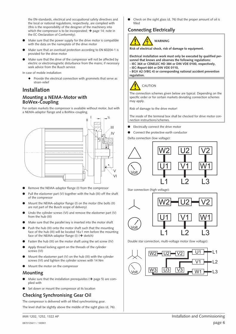
InstallationMounting a NEMA-Motor withBoWex-CouplingFor certain markets the compressor is available without motor, but witha NEMA-adaptor flange and a BoWex-coupling.
● Remove the NEMA-adaptor flange (I) from the compressor
● Pull the elastomer part (V) together with the hub (III) off the shaftof the compressor
● Mount the NEMA-adaptor flange (I) on the motor (the bolts (II)are not part of the Busch scope of delivery)
● Undo the cylinder screws (VI) and remove the elastomer part (V)from the hub (III)
● Make sure that the parallel key is inserted into the motor shaft
● Push the hub (III) onto the motor shaft such that the mountingface of the hub (III) will be located 16±1 mm before the mountingface of the NEMA-adaptor flange (I) (� sketch)
● Fasten the hub (III) on the motor shaft using the set screw (IV)
● Apply thread locking agent on the threads of the cylinderscrews (VI)
● Mount the elastomer part (V) on the hub (III) with the cylinderscrews (VI) and tighten the cylinder screws with 14 Nm
● Mount the motor on the compressor
Mounting● Make sure that the installation prerequisites (� page 5) are com-
plied with
● Set down or mount the compressor at its location
Checking Synchronising Gear OilThe compressor is delivered with oil filled synchronising gear.
The level shall be slightly above the middle of the sight glass (d, 76).
● Check on the sight glass (d, 76) that the proper amount of oil isfilled
Connecting Electrically
WARNING_ab
Risk of electrical shock, risk of damage to equipment.
Electrical installation work must only be executed by qualified per-sonnel that knows and observes the following regulations:- IEC 364 or CENELEC HD 384 or DIN VDE 0100, respectively,- IEC-Report 664 or DIN VDE 0110,- BGV A2 (VBG 4) or corresponding national accident preventionregulation.
CAUTION_a
The connection schemes given below are typical. Depending on thespecific order or for certain markets deviating connection schemesmay apply.
Risk of damage to the drive motor!
The inside of the terminal box shall be checked for drive motor con-nection instructions/schemes.
● Electrically connect the drive motor
● Connect the protective earth conductor
Delta connection (low voltage):
Star connection (high voltage):
Double star connection, multi-voltage motor (low voltage):
MM 1202, 1252, 1322 AP Installation and Commissioning
0870135611 / 100901 page 6
III
III
IV
VVI

Star connection, multi-voltage motor (high voltage):
CAUTION_a
Operation in the wrong direction of rotation can destroy thecompressor in short time.
Prior to starting-up it must be made sure that the compressor is op-erated in the proper direction (clockwise rotating field).
● Determine the intended direction of rotation with the arrow (stuckon or cast)
● “Bump” the drive motor
● Watch the fan wheel of the drive motor and determine the direc-tion of rotation just before the fan wheel stops
If the rotation must be changed:
◆ Switch any two of the drive motor wires
Connecting Lines/Pipes● Connect the suction line
Installation without suction line:
◆ Make sure that the gas inlet (c) is open
● Connect the pressure line
● Make sure that all provided covers, guards, hoods etc. aremounted
● Make sure that cooling air inlets and outlets are not covered or ob-structed and that the cooling air flow is not affected adversely inany other way
Recording of Operational ParametersAs soon as the compressor is operated under normal operatingconditions:
● Measure the drive motor current and record it as reference for fu-ture maintenance and troubleshooting work
Operation NotesUse
CAUTION_a
The compressor is designed for operation under the conditions de-scribed below.
In case of disregard risk of damage or destruction of the compressorand adjoining plant components!
Risk of injury!
The compressor must only be operated under the conditions de-scribed below.
The compressor is intended for
– the compression
of
– air and other dry, non-aggressive, non-toxic and non-explosivegases
Conveying media with a lower or higher density than air leads to an in-creased thermal and/or mechanical load on the compressor and is per-missible only after prior consultation with Busch.
Max. allowed temperature of the inlet gas: 40 °C
The gas shall be free from vapours that would condensate under thetemperature and pressure conditions inside the compressor.
The compressor is intended for the placement in a non-potentially ex-plosive environment.
The compressor is thermally suitable for continuous operation(100 percent duty).
Max. permissible number of startings per hour: 12
The maximum allowed pressure on the pressure connection (l) is0.7 ... 2.0 barg (the nameplate of the compressor indicates the validpressure). By means of process control and/or pressure relief valves itmust be made sure that the maximum allowed pressure will not beexceeded.
As a rule ambient pressure must be present at the gas inlet. Deviationsare indicated on the nameplate of the compressor.
The safety valve (k) on the compressor protects the compressor againstoverload only. It is no pressure limiting device in terms of EN 1012-1for the pressure system. It is not designed for frequent use and musttherefore not be used as a system pressure regulating valve.
CAUTION_ac
During operation the surface of the compressor may reach tempera-tures of more than 70 °C.
Risk of burns!
The compressor shall be protected against contact during operation,it shall cool down prior to a required contact or heat protectiongloves shall be worn.
CAUTION_a4
The compressor emits noise of high intensity in a narrow band.
Risk of damage to the hearing.
Persons staying in the vicinity of a non noise insulated compressorover extended periods shall wear ear protection.
● Make sure that all provided covers, guards, hoods etc. remainmounted
● Make sure that protective devices will not be disabled
● Make sure that cooling air inlets and outlets will not be covered orobstructed and that the cooling air flow will not be affected ad-versely in any other way
● Make sure that the installation prerequisites (� page 5: InstallationPrerequisites) are complied with and will remain complied with,particularly that a sufficient cooling will be ensured
MM 1202, 1252, 1322 AP Installation and Commissioning
0870135611 / 100901 page 7

Maintenance
DANGER_age32
In case the compressor conveyed gas that was contaminated withforeign materials which are dangerous to health, harmful materialcan reside in filters.
Danger to health during inspection, cleaning or replacement of fil-ters.
Danger to the environment.
Personal protective equipment must be worn during the handlingof contaminated filters.
Contaminated filters are special waste and must be disposed ofseparately in compliance with applicable regulations.
CAUTION_ac
During operation the surface of the compressor may reach tempera-tures of more than 70 °C.
Risk of burns!
● Prior to disconnecting connections make sure that the connectedpipes/lines are vented to atmospheric pressure
Maintenance ScheduleNote: The maintenance intervals depend very much on the individualoperating conditions. The intervals given below shall be considered asstarting values which should be shortened or extended as appropriate.Particularly heavy duty operation, such like high dust loads in the envi-ronment or in the process gas, other contaminations or ingress of pro-cess material, can make it necessary to shorten the maintenanceintervals significantly.
Monthly:● Make sure that the compressor is shut down and locked against in-
advertent start up
● Check the inlet air filter (i), if necessary replace
In case of operation in a dusty environment:
◆ Clean as described under� page 8: Every 6 Months:
Every 3 Months:● Make sure that the compressor is shut down
● Check the level of the synchronising gear oil
The level shall be slightly above the middle of the sight glass (d, 76).
The level of the synchronising gear should stay constant over the life-time of the oil. If the level does fall, the gear is leaky and thecompressor requires repair (Busch service).
Every 6 Months:● Make sure that the housing is free from dust and dirt, clean if nec-
essary
● Make sure that the compressor is shut down and locked against in-advertent start up
● Remove the acoustic enclosure
Note: Make sure that the foam mats do not get soaked with water
● Clean the fan cowlings, fan wheels, the ventilation grilles and cool-ing fins
● Mount the acoustic enclosure
Every Year:● Make sure that the compressor is shut down and locked against in-
advertent start up
● Replace the inlet air filter (i)
● Check the inlet screen, clean if necessary
Note: As there is an inlet air filter upstream the inlet screen, the inletscreen should not show soiling. A soiled inlet screen indicates that thefilter is either broken through or improperly inserted.
Every 20000 Operating Hours, At the Latest after6 Years:Note: The change interval of 20000 operating hours is valid for thegear oil Busch VE 101 only. Other gear oils reduce the change interval.
● Change the synchronising gear oil
Changing Synchronising Gear Oil● Make sure that the compressor is shut down and locked against in-
advertent start up
● Remove the eyebolt (f)
● Remove the lid (424)
● Undo the venting valve (72) for venting
● Place a drain tray underneath the drain plug (e, 80)
● Open the drain plug (e, 80) and drain the oil
● Make sure that the seal ring on the drain plug (e, 80) is service-able, replace if necessary
● Firmly reinsert the drain plug (e, 80) together with the seal ring
● Remove the venting valve (72) completely
● Fill in new gear oil until the level is slightly above the middle of thesight glass (d, 76)
● Make sure that the seal ring on the venting valve (72) is undam-aged, if necessary replace the venting valve (72)
● Firmly reinsert the venting valve (72) together with the seal ring
● Mount the lid (424)
● Reinsert the eyebolt (f)
● Dispose of the used oil in compliance with applicable regulations
Overhaul
CAUTION_a
In order to achieve best efficiency and a long life the compressorwas assembled and adjusted with precisely defined tolerances.
This adjustment will be lost during dismantling of the compressor.
It is therefore strictly recommended that any dismantling of thecompressor that is beyond of what is described in this manual shallbe done by Busch service.
MM 1202, 1252, 1322 AP Maintenance
0870135611 / 100901 page 8
72 424 615
76/77 80/81

DANGER_age32
In case the compressor conveyed gas that was contaminated withforeign materials which are dangerous to health, harmful materialcan reside in pores, gaps and internal spaces of the compressor.
Danger to health during dismantling of the compressor.
Danger to the environment.
Prior to shipping the compressor shall be decontaminated as goodas possible and the contamination status shall be stated in a “Dec-laration of Contamination” (form downloadable fromwww.busch-vacuum.com).
Busch service will only accept compressors that come with a completelyfilled in and legally binding signed “Declaration of Contamination”(form downloadable from www.busch-vacuum.com).
Removal from ServiceTemporary Removal from Service● Prior to disconnecting pipes/lines make sure that all pipes/lines are
vented to atmospheric pressure
Recommissioning● Observe the chapter Installation and Commissioning (� page 5)
Dismantling and Disposal
DANGER_age32
In case the compressor conveyed gas that was contaminated withforeign materials which are dangerous to health, harmful materialcan reside in pores, gaps and internal spaces of the compressor.
Danger to health during dismantling of the compressor.
Danger to the environment.
During dismantling of the compressor personal protective equip-ment must be worn.
The compressor must be decontaminated prior to disposal.
● Drain the oil
● Make sure that materials and components to be treated as specialwaste have been separated from the compressor
● Make sure that the compressor is not contaminated with harmfulforeign material
According to the best knowledge at the time of printing of this manualthe materials used for the manufacture of the compressor involve norisk.
● Dispose of the used oil in compliance with applicable regulations
● Dispose of the compressor as scrap metal
MM 1202, 1252, 1322 AP Removal from Service
0870135611 / 100901 page 9

Troubleshooting
WARNING_ab
Risk of electrical shock, risk of damage to equipment.
Electrical installation work must only be executed by qualified personnel that knows and observes the following regulations:- IEC 364 or CENELEC HD 384 or DIN VDE 0100, respectively,- IEC-Report 664 or DIN VDE 0110,- BGV A2 (VBG 4) or equivalent national accident prevention regulation.
CAUTION_ac
During operation the surface of the compressor may reach temperatures of more than 70 °C.
Risk of burns!
Let the compressor cool down prior to a required contact or wear heat protection gloves.
Problem Possible Cause Remedy
The compressor does not reach the usual pres-sure
The drive motor draws a too high current(compare with initial value after commission-ing)
Filling the system takes too long
Building up pressure in the system takes toolong
The pressure system or pressure line is notleak-tight
Check the hose or pipe connections for possi-ble leak
The pressure relief valve/regulating system ismisadjusted or defective
Adjust, repair or replace, respectively
The screen in the gas inlet (c) is partiallyclogged
Clean the screen
If cleaning is required too frequently install afilter upstream
The filter (i) on the gas inlet (c) is partiallyclogged
Clean or replace the inlet air filter (i), respec-tively
Partial clogging in the suction, discharge orpressure line
Remove the clogging
Long suction, discharge or pressure line withtoo small diameter
Use larger diameter
The valve disk of the inlet non-return valve isstuck in closed or partially open position
Disassemble the inlet, clean the screen and thevalve (p) as required and reassemble
Internal parts are worn or damaged Repair the compressor (Busch service)
The compressor does not start The drive motor is not supplied with the cor-rect voltage or is overloaded
Supply the drive motor with the correct volt-age
The drive motor starter overload protection istoo small or trip level is too low
Compare the trip level of the drive motorstarter overload protection with the data onthe nameplate, correct if necessary
In case of high ambient temperature: set thetrip level of the drive motor starter overloadprotection 5 percent above the nominal drivemotor current
One of the fuses has blown Check the fuses
The connection cable is too small or too longcausing a voltage drop at the compressor
Use sufficiently dimensioned cable
MM 1202, 1252, 1322 AP Troubleshooting
0870135611 / 100901 page 10

The compressor or the drive motor is blocked Make sure the drive motor is disconnectedfrom the power supply
Remove the fan cover
Try to turn the drive motor with thecompressor by hand
If the unit is still frozen: remove the drive mo-tor and check the drive motor and thecompressor separately
If the compressor is blocked:
Repair the compressor (Busch service)
The drive motor is defective Replace the drive motor (Busch service)
(the proper function of the fan wheel requiresthe precise adjustment of the coupling on themotor shaft and on the pump shaft; thereforethe motor can be mounted by the Busch ser-vice only)
The compressor is blocked Solid foreign matter has entered thecompressor
Repair the compressor (Busch service)
Make sure the suction line is equipped with ascreen
If necessary additionally provide a filter
Corrosion in the compressor from remainingcondensate
Repair the compressor (Busch service)
Check the process
The compressor was run in the wrong direc-tion
Repair the compressor (Busch service)
When connecting the compressor make surethe compressor will run in the correct direction(� page 6: Installation)
The drive motor is running, but thecompressor stands still
The coupling between the drive motor andthe compressor is defective
Replace the coupling element
(the proper function of the fan wheel requiresthe precise adjustment of the coupling on themotor shaft and on the pump shaft; thereforethe coupling element can be replaced by theBusch service only)
The compressor starts, but labours or runsnoisily or rattles
The drive motor draws a too high current(compare with initial value after commission-ing)
Loose connection(s) in the drive motor termi-nal box
Not all drive motor coils are properly con-nected
The drive motor operates on two phases only
Check the proper connection of the wiresagainst the connection diagram
(particularly on motors with six coils)
Tighten or replace loose connections
The compressor runs in the wrong direction Verification and rectification� page 5: Instal-lation and Commissioning
Foreign objects in the compressor
Stuck bearings
Repair the compressor (Busch service)
The compressor runs very noisily Defective bearings Repair the compressor (Busch service)
Worn coupling element Replace the coupling element
Low oil level in the synchronising gear The synchronising gear is leaky
Repair the compressor (Busch service)
Synchronising gear damaged due to operationwith low oil level
Repair the compressor (Busch service)
The compressor runs very hot Insufficient air ventilation Make sure that the cooling of the compressoris not impeded by dust/dirt
Clean the fan cowlings, the fan wheels, theventilation grilles and the cooling fins
Install the compressor in a narrow space onlyif sufficient ventilation is ensured
Ambient temperature too high Observe the permitted ambient temperatures
Temperature of the inlet gas too high Observe the permitted temperatures for theinlet gas
MM 1202, 1252, 1322 AP Troubleshooting
0870135611 / 100901 page 11

Insufficient gas transfer Provide a pressure relief valve
Mains frequency or voltage outside tolerancerange
Provide a more stable power supply
In case a pressure relief valve/regulating systemis installed:
The pressure relief valve/regulating system ismisadjusted or defective
Adjust, repair or replace, respectively
Partial clogging of filters or screens
Partial clogging in the suction, discharge orpressure line
Remove the clogging
Long suction, discharge or pressure line withtoo small diameter
Use larger diameter
MM 1202, 1252, 1322 AP Troubleshooting
0870135611 / 100901 page 12

Spare PartsNote: When ordering spare parts or accessories acc. to the table belowplease always quote the type (“Type”) and the serial no. (“No”) of thecompressor. This will allow Busch service to check if the compressor iscompatible with a modified or improved part.
The exclusive use of genuine spare parts and consumables is a pre-requisite for the proper function of the compressor and for the grant-ing of warranty, guarantee or goodwill.
Your point of contact for service and spare parts in the UnitedKingdom:
Busch (UK) Ltd.Hortonwood 30-35TelfordShropshireTF1 7YBTel: 01952 677 432Fax: 01952 677 423
Your point of contact for service and spare parts in Ireland:
Busch Ireland Ltd.A10-11 Howth Junction Business CentreKilbarrack, Dublin 5Tel: +353 (0)1 8321466Fax: +353 (0)1 8321470
Your point of contact for service and spare parts in the USA:
Busch lnc.516-B Viking DriveVirginia Beach, VA 23452Tel: 1-800-USA-PUMP (872-7867)
Your point of contact for service and spare parts in Canada:
Busch Vacuum Technics Inc.1740, Boulevard Lionel BertrandBoisbriand (Montréal)Québec J7H 1N7Tel: 450 435 6899Fax: 450 430 5132
Your point of contact for service and spare parts in Australia:
Busch Australia Pty. Ltd.30 Lakeside DriveBroadmeadows, Vic. 3047Tel: (03) 93 55 06 00Fax: (03) 93 55 06 99
Your point of contact for service and spare parts in New Zealand:
Busch New Zealand Ltd.Unit D, Arrenway DriveAlbany, Auckland 1311P O Box 302696North Harbour, Auckland 1330Tel: 0-9-414 7782Fax: 0-9-414 7783
Find the list of Busch companies all over the world (by the time of thepublication of these installation and operating instructions) on� page 16 (rear cover page).
Find the up-to-date list of Busch companies and agencies all over theworld on the internet at www.busch-vacuum.com.
Pos. Part Qty Part no.
72 Venting valve (=oil fill plug)with seal ring 1 0543 107 407
76 Sight glass 1 0583 000 001
77 Seal ring for sight glass 1 0480 000 271
80 Plug with magnet and seal ring 1 0415 134 870
81 Seal ring for plug with magnet 1 0482 137 352
— Filter cartridge, paper, for inletfilter 1 0532 000 004
Spare Parts KitsSpare parts kit Part no.
Overhaul kit (incl. set of seals; insert for flexiblecoupling for Rotex only) 0993 134 022
Set of seals/gaskets 0990 134 021
OilDenomination Busch VE 101
ISO-VG 100
Base Diester
Density [g/cm³] 0.96
Kinematic viscosity at 40 °C[mm²/s] 95
Kinematic viscosity at 100 °C[mm²/s] 9.5
Flashpoint [°C] 255
Pourpoint [°C] –30
Part no. 1 l packaging 0831 000 099
Part no. 5 l packaging 0831 000 100
Filling quantity, approx. [l] 1
MM 1202, 1252, 1322 AP Spare Parts
0870135611 / 100901 page 13

MM 1202, 1252, 1322 AP EC-Declaration of Conformity
0870135611/ 100927 page 14
EC-Declaration of Conformity Note : This Declaration of Conformity and the CE-mark affixed to the nameplate are valid for the machine within the Busch scope of delivery. This Declaration of Conformity is issued under the sole responsibility of the manufacturer. When this machine is integrated into a superordinate machinery the manufacturer of the superordinate machinery (this can be the operating company, too) must conduct the conformity assessment process for the superordinate machine or plant, issue the Declaration of Conformity for it and affix the CE-mark.
We
Busch Produktions GmbH Schauinslandstr. 1 79689 Maulburg Germany
Declare that the vacuum pumps MM 1202, 1252, 1322 AP
with a serial number from D1601… to D1752…
has (have) been manufactured in accordance with the European Directives:
• ‘Machinery’ 2006/42/EC
• ‘Electromagnetic Compatibility’ 2014/30/EU
• ‘RoHS’ 2011/65/EU, restriction of the use of certain hazardous substances in electrical and electronic equipment
and following the standards.
Standard Title of the Standard
EN ISO 12100: 2010 Safety of machinery –General principles for design –Risk assessment and risk reduction
EN ISO 13857: 2008 Safety of machinery - Safety distances to prevent hazard zones being reached by the upper and lower limbs
EN 1012-1: 2010 EN 1012-2: 1996 + A1: 2009
Compressors and vacuum pumps - Safety requirements - Part 1 and Part 2
EN ISO 2151: 2008 Acoustics - Noise test code for compressors and vacuum pumps - Engineering method (grade 2)
EN 60204-1: 2006 Safety of machinery - Electrical equipment of machines - Part 1: General requirements
EN 61000-6-2: 2005 Electromagnetic compatibility (EMC) - Generic immunity standards. Immunity for industrial environments
EN 61000-6-4: 2007 + A1: 2011 Electromagnetic compatibility (EMC) - Generic immunity standards. Emission standard for industrial environments
EN ISO 13849-1:2015 (1) Safety of machinery - Safety-related parts of control systems - Part 1: General principles for design
Manufacturer
Dr.-Ing. Karl Busch General Director
Person authorized to compile the technical file
Andrej Riwe Technical writer
Maulburg, 04.04.2016

Technical DataFor motor connection parameters see nameplate
Type
Freq
uenc
y[H
z]
Ultim
ate
wor
king
pres
sure
*
[bar
(g)]
Nom
inal
mot
orra
ting*
*
[kW
]
Nom
inal
spee
d
[min
-1 ]Vo
lum
eflo
w[m
³/h]
Soun
dpr
essu
relev
el
(EN
ISO
2151
) with
silen
cer,
mea
sure
dat
+0.7
bar g
[db(
A)]
Weig
ht[k
g]
Ambi
ent t
empe
ratu
rera
nge
[°C]
Ambi
ent p
ress
ure
Sync
hron
ising
gear
oil q
ty
[l] Sync
hron
ising
gear
oil f
illed
ex-w
orks
MM 1202 AP
50
0.7 5.5
3000 200 80
~250
0...
40
atm
osph
eric
1.0
Busc
hV
E10
1
1.2 7.5 ~255 ... 280
2.0 11 ~280 ... 295
60
0.7 7.5
3600 240 83
~270
1.0 8.6 ~280
1.8 12.6 ~280
2.0 17.3 ~310
MM 1252 AP
50
0.9 7.5
3000 250 81
~265 ... 290
1.6 11 ~290 ... 305
2.0 15 ~300 ... 315
60
0.7 8.6
3600 300 84
~290
1.4 12.6 ~290
2.0 17.3 ~300
MM 1322 AP
50
1.0 11
3000 300 82
~305 ... 315
1.7 15 ~330
2.0 18.5 ~325 ... 355
60
0.8 12.6
3600 360 85
~305
1.5 17.3 ~330
2.0 21.3 ~320
*valid ultimate working pressure see nameplate
**may vary depending on specific order
MM 1202, 1252, 1322 AP Technical Data
0870135611 / 100901 page 15

Busch – All over the World in Industry www.busch-vacuum.comAustraliaBusch Australia Pty. Ltd.30 Lakeside DriveBroadmeadows, Vic. 3047Tel: (03) 93 55 06 00Fax: (03) 93 55 06 99
AustriaBusch Austria GmbHIndustriepark Nord2100 KorneuburgTel: 02262 / 756 65-0Fax: 02262 / 756 65-20
BelgiumBusch N.V./Busch SAKruinstraat 79160 LokerenTel: (0)9 / 348 47 22Fax: (0)9 / 348 65 35
BrazilBusch do Brasil Ltda.Rod. Edgard Máximo Zambotto, Km 6413240-000 Jarinu-SPTel: (55) 11-4016 1400/5277Fax: (55) 11-4016 5399
CanadaBusch Vacuum Technics Inc.1740, Boulevard Lionel BertrandBoisbriand (Montréal)Québec J7H 1N7Tel: 450 435 6899Fax: 450 430 5132
ChileBusch Chile S. A.Calle El Roble N° 375-GLampa - SantiagoTel: (56-2) 7387092Fax: (56-2) 7387092
ChinaBusch Vacuum (Shanghai) Co., LtdNo.5, Lane 195 Xipu RoadSongjiang Industrial Estate East New ZoneShanghai 201611 PRCTel: +86 (0)21 67600800Fax: +86 (0)21 67600700
Czech RepublicBusch Vakuum s.r.o.Pra�ákova 10619 00 Horní HeršpiceBrnoTel: +420 543 42 48 55Fax: +420 543 42 48 56
DenmarkBusch Vakuumteknik A/SParallelvej 118680 RyTel: +45 87 88 07 77Fax: +45 87 88 07 88
FinlandBusch Vakuumteknik OySinikellontie 401300 VANTAATel: 09 774 60 60Fax: 09 774 60 666
FranceBusch France S.A.Parc Technologiquede Bois Chaland CE 292291029 Evry CedexTel: 01 69 89 89 89Fax: 01 60 86 16 74
GermanyDr.-Ing. K. Busch GmbHSchauinslandstr. 179689 MaulburgTel: (0 76 22) 6 81-0Fax: (0 76 22) 6 81-194e-mail: [email protected]
Dr.-Ing. K. Busch GmbHNiederlassung NordErnst-Abbe-Str. 1-325451 QuickbornTel: (0 41 06) 7 99 67-0Fax: (0 41 06) 7 99 67-77
Dr.-Ing. K. Busch GmbHNiederlassung WestNordring 3564807 DieburgTel: (0 60 71) 92 82-0Fax: (0 60 71) 14 71
Dr.-Ing. K. Busch GmbHAußenstelle NeuenradeBreslauer Str. 3658809 NeuenradeTel: (0 23 92) 50 29 92Fax: (0 23 92) 50 72 11
Dr.-Ing. K. Busch GmbHNiederlassung Süd-OstGewerbestraße 390579 LangenzennTel: (09 01) 90 25-0Fax: (09 01) 90 25-25
Dr.-Ing. K. Busch GmbHAußenstelle Zella-MehlisAm Rain 1198544 Zella-MehlisTel: (0 36 82) 46 92 71Fax: (0 36 82) 46 92 73
Dr.-Ing. K. Busch GmbHAußenstelle Meitingen-OstendorfGrüntenweg 886405 Meitingen-OstendorfTel: (0 82 71) 426-341Fax: (0 82 71) 426-342
IndiaBusch Vacuum India Pvt Ltd.Plot No. 110, Sector 7PCNTDA, BhosariPune 411026, MaharashtraTel: (0)206410 2886Fax: (0)202711 2838
IrelandBusch Ireland Ltd.A10-11 Howth Junction Business CentreKilbarrack, Dublin 5Tel: 00353 1 832 1466Fax: 00353 1 832 1470
IsraelBusch Israel Ltd.1 Mevo Sivan StreetQiryat Gat 82022, IsraelTel: +972 (0)8 6810485Fax +972 (0)8 6810486
ItalyBusch Italia S.r.l.Via Ettore Majorana, 1620054 Nova MilaneseTel: 0362 370 91Fax: 0362 370 999
JapanNippon Busch K.K.1-23-33, MegumigaokaHiratsuka City, KanagawaJapan 259-1220Tel: 0463-50-4000Fax: 0463-50-4004
KoreaBusch Korea Ltd.392-1 Yangji-Ri, Yangji-Myun,Yongin-si, Kyunggi-DoTel: 031) 321-8114Fax: 031) 321 4330
MalaysiaBusch (Malaysia) Sdn Bhd.6 Jalan Taboh 33/22Shah Alam Technology ParkSection 3340400 Shah AlamSelangor D. E.Tel: 03 5122 2128Fax 03 5122 2108
MexicoBusch Vacuum Mexico S de RL de CVTlaquepaque 4865, Los AltosMonterrey, Nuevo LeonMexico 64370Tel: (81) 8311-1385Fax: (81) 8311-1386
NetherlandsBusch B.V.Pompmolenlaan 23447 GK WoerdenPostbus 20913440 DB WoerdenTel: (0)348 - 462300Fax: (0)348 - 422939
New ZealandBusch New Zealand Ltd.Unit D, 41 Arrenway DriveAlbany 0632AucklandTel: 09 414 7782Fax: 09 414 7783
NorwayBusch Vakuumteknikk ASHestehagen 21440 DrøbakTel: 64 98 98 50Fax: 64 93 66 21
PolandBusch Polska Sp. z o.o.Ul. Chopina 2787800 W�oc�awekTel: (054) 2315400Fax: (054) 2327076
PortugalBusch lbérica S.A., Sucursal em PortugalZona Industrial Raso de Travassô, Fracção B, Armazém 23750-753 AguedaAveiro, PortugalTel: +351 234 648 070Fax: +351 234 648 068
RussiaBusch Vacuum Russia OOOKotlyakovskaya str., 6/9115201 MoscowTel: +7 495 6486726Fax: +7 495 6486724
SingaporeBusch Vacuum Singapore Pte Ltd20 Shaw Road#01-03 Ching Shine BuildingSingapore 36 79 56Tel: (65) 6488 0866Fax: (65) 6288 0877
SpainBusch Ibérica S.A.C/ Jaume Ferran, 6-8Pol. Ind. Coll de la Manya08403 GranollersTel: +34 93 861 61 60Fax: +34 93 840 91 56
SwedenBusch Vakuumteknik ABBråta Industriområde435 33 MölnlyckeTel: 031 - 338 00 80Fax: 031 - 338 00 89
SwitzerlandBusch AGWaldweg 224312 MagdenTel: 061 / 845 90 90Fax: 061 / 845 90 99
TaiwanBusch Taiwan Corporation1F. No. 69, Sec. 3, Beishen Rd.Shenkeng Township,Taipei Country,Taiwan (222), R.O.CTel: (02) 2662 0775Fax: (02) 2662 0796
ThailandBusch Vacuum (Thailand) Co., Ltd.888/30 Moo19, Soi Yingcharoen, Bangplee-Tamru Rd.,Bangpleeyai, Bangplee, Samutprakarn 10540 ThailandTel: (66) 2-382-5428Fax: (66) 2-382-5429
TurkeyVAKUTEKEmlak Kredi Ishani No: 17981130 Üsküdar-IstanbulTel: (216) 310 0573Fax: (216) 343 5126
United KingdomBusch (UK) LtdHortonwood 30-35Telford Shropshire TF1 7YBTel: 01952 677 432Fax: 01952 677 423
USABusch, Inc.516-B Viking DriveVirginia Beach, VA 23452Tel: (757) 463-7800Fax: (757) 463 7407
Semiconductor Vacuum Group Inc.Morgan Hill, CA 95037Tel: (408) 955 1900Fax: (408) 955 0229
MM 1202, 1252, 1322 AP Busch – All over the World in Industry
0870135611 / 100901 page 16