Embed Size (px)
Citation preview
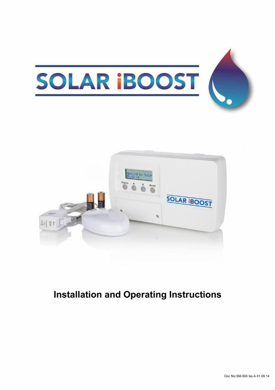
Installation and Operating Instructions
Doc No:SM-500 Iss A 01.09.14
2
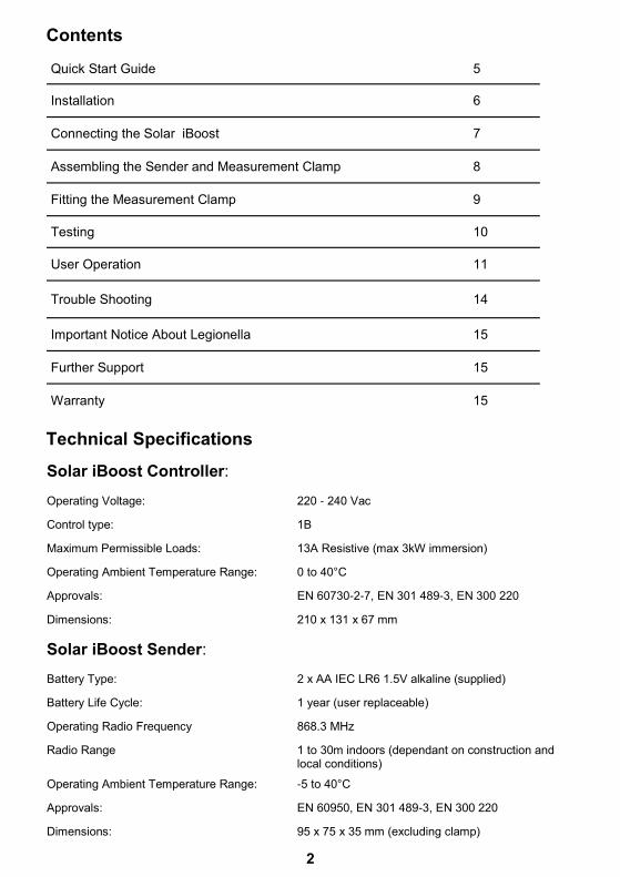
Quick Start Guide 5
Installation 6
Connecting the Solar iBoost 7
Assembling the Sender and Measurement Clamp 8
Fitting the Measurement Clamp 9
Testing 10
User Operation 11
Trouble Shooting 14
Important Notice About Legionella 15
Further Support 15
Warranty 15
Solar iBoost Controller: Operating Voltage: 220 - 240 Vac
Control type: 1B
Maximum Permissible Loads: 13A Resistive (max 3kW immersion)
Operating Ambient Temperature Range: 0 to 40°C
Approvals: EN 60730-2-7, EN 301 489-3, EN 300 220
Dimensions: 210 x 131 x 67 mm
Solar iBoost Sender: Battery Type: 2 x AA IEC LR6 1.5V alkaline (supplied)
Battery Life Cycle: 1 year (user replaceable)
Operating Radio Frequency 868.3 MHz
Radio Range 1 to 30m indoors (dependant on construction and local conditions)
Operating Ambient Temperature Range: -5 to 40°C
Approvals: EN 60950, EN 301 489-3, EN 300 220
Dimensions: 95 x 75 x 35 mm (excluding clamp)
Contents
Technical Specifications
3
1. The electrical installation of this device must only be undertaken by a suitably trained and qualified electrician; all local safety standards must be observed. All work must satisfy Building/IEE Wiring regulations in force at the time.
2. Solar iBoost is suitable for water heating tanks with an immersion heater rated up to 3kW which MUST include a working thermostat.
3. There should be NO electronic controls between the Solar iBoost and the
immersion heater, only direct connections to the immersion and mechanical thermostat are suitable for Solar iBoost.
Thank you for purchasing a Solar iBoost.
Solar iBoost Features.
Manual Boost and programmable Timed Boost (eg. For economy settings)
A single, battery powered, wireless energy sensor - Sender
Displayed energy saving information
Up to 3kW immersion heater capability
Dual immersion heater capability to enable timed settings for water heating from
the grid where needed
These instructions provide information on the installation, operation and programming of the unit. Please keep this booklet safe for future reference.
The Solar iBoost is designed to be used in conjunction with micro-generation systems, e.g. solar PV, where surplus energy generated can be stored within a domestic hot water cylinder in the form of hot water. By monitoring the amount of energy being exported to the National Grid the Solar iBoost unit will divert energy into an immersion heater when the energy generated exceeds the amount of energy consumed within the property. Solar iBoost controls the energy delivered to the immersion heater in proportion to that exported.
Before use please read these instructions carefully
Checks Before Commencing Installation Please note and ensure the following before commencing any installation...
4
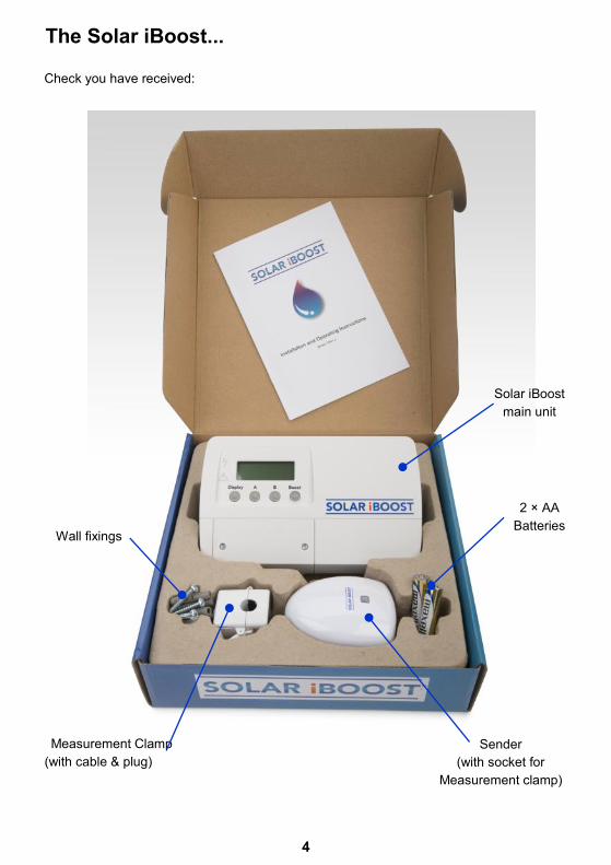
The Solar iBoost...
Check you have received:
Solar iBoost
main unit
Measurement Clamp
(with cable & plug)
Wall fixings
2 × AA
Batteries
Sender
(with socket for
Measurement clamp)
5
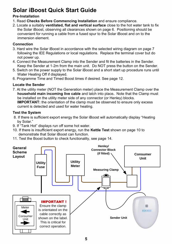
Pre-Installation
1. Read Checks Before Commencing Installation and ensure compliance. 2. Locate a suitably ventilated, flat and vertical surface close to the hot water tank to fix
the Solar iBoost, observing all clearances shown on page 6. Positioning should be convenient for running a cable from a fused spur to the Solar iBoost and on to the
immersion element.
Connection
3. Hard wire the Solar iBoost in accordance with the selected wiring diagram on page 7 following the IEE Regulations or local regulations. Replace the terminal cover but do not power up.
4. Connect the Measurement Clamp into the Sender and fit the batteries in the Sender. Keep the Sender at 1-2m from the main unit. Do NOT press the button on the Sender.
5. Switch on the power supply to the Solar iBoost and a short start up procedure runs until Water Heating Off if displayed.
6. Programme Time and Timed Boost times if desired. See page 12.
Locate the Sender
7. At the utility meter (NOT the Generation meter) place the Measurement Clamp over the household main incoming live cable and latch into place. Note that the Clamp must be installed on the utility meter side of any connector (or Henley) blocks.
IMPORTANT: the orientation of the clamp must be observed to ensure only excess current is detected and used for water heating.
Test the System
8. If there is sufficient export energy the Solar iBoost will automatically display “Heating by Solar.”
9. If “Tank Hot” displays run off some hot water. 10. If there is insufficient export energy, run the Kettle Test shown on page 10 to demonstrate that Solar iBoost can function. 11. Test the Boost button to check functionality, see page 14.
Meter
ConsumerUnit
Ensure the clamp
is orientated on the
cable correctly as
shown on the label.
This is critical for
correct operation.
IMPORTANT !
Utility
Fuse
Consumer
Unit
Measuring Clamp
Utility
Meter
Henley/
Connector Block
(if fitted)
Sender Unit
Solar iBoost Quick Start Guide
General Scheme Layout
6
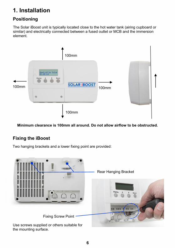
Two hanging brackets and a lower fixing point are provided:
1. Installation
100mm
100mm
100mm 100mm
Minimum clearance is 100mm all around. Do not allow airflow to be obstructed.
Fixing the iBoost
Positioning
The Solar iBoost unit is typically located close to the hot water tank (airing cupboard or similar) and electrically connected between a fused outlet or MCB and the immersion element.
Rear Hanging Bracket
Fixing Screw Point
Use screws supplied or others suitable for the mounting surface.
7
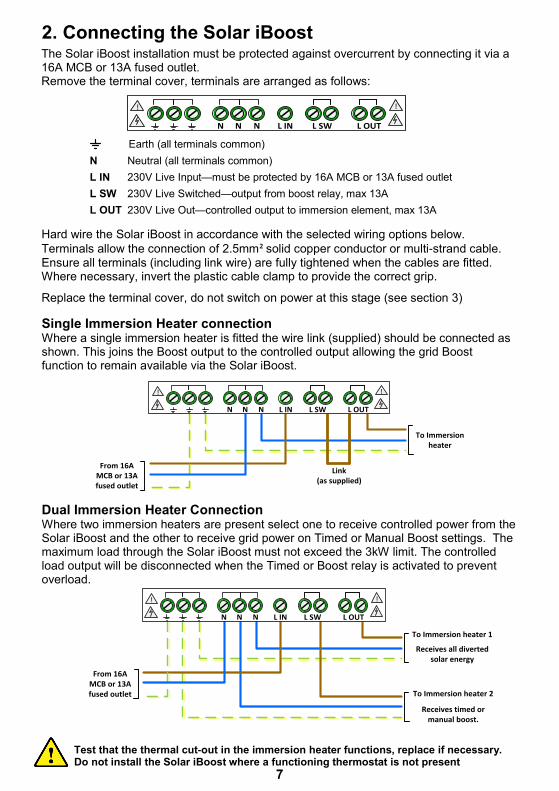
2. Connecting the Solar iBoost
N L IN L SWN N L OUT
! !
Hard wire the Solar iBoost in accordance with the selected wiring options below.
Terminals allow the connection of 2.5mm² solid copper conductor or multi-strand cable.
Ensure all terminals (including link wire) are fully tightened when the cables are fitted. Where necessary, invert the plastic cable clamp to provide the correct grip.
Replace the terminal cover, do not switch on power at this stage (see section 3)
The Solar iBoost installation must be protected against overcurrent by connecting it via a 16A MCB or 13A fused outlet. Remove the terminal cover, terminals are arranged as follows:
Single Immersion Heater connection Where a single immersion heater is fitted the wire link (supplied) should be connected as shown. This joins the Boost output to the controlled output allowing the grid Boost function to remain available via the Solar iBoost.
From 16A MCB or 13A fused outlet
To Immersion heater
Link(as supplied)
N L IN L SWN N L OUT
! !
Dual Immersion Heater Connection Where two immersion heaters are present select one to receive controlled power from the Solar iBoost and the other to receive grid power on Timed or Manual Boost settings. The maximum load through the Solar iBoost must not exceed the 3kW limit. The controlled load output will be disconnected when the Timed or Boost relay is activated to prevent overload.
From 16A MCB or 13A fused outlet
To Immersion heater 1
Receives all diverted solar energy
N L IN L SWN N L OUT
! !
To Immersion heater 2
Receives timed or manual boost.
Earth (all terminals common)
N Neutral (all terminals common)
L IN 230V Live Input—must be protected by 16A MCB or 13A fused outlet
L SW 230V Live Switched—output from boost relay, max 13A
L OUT 230V Live Out—controlled output to immersion element, max 13A
Test that the thermal cut-out in the immersion heater functions, replace if necessary. Do not install the Solar iBoost where a functioning thermostat is not present
8
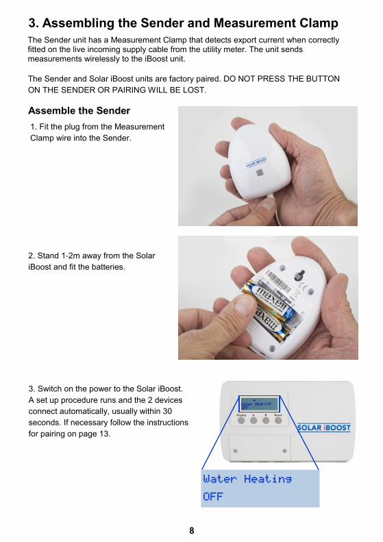
The Sender unit has a Measurement Clamp that detects export current when correctly fitted on the live incoming supply cable from the utility meter. The unit sends measurements wirelessly to the iBoost unit.
3. Assembling the Sender and Measurement Clamp
2. Stand 1-2m away from the Solar
iBoost and fit the batteries.
1. Fit the plug from the Measurement
Clamp wire into the Sender.
3. Switch on the power to the Solar iBoost.
A set up procedure runs and the 2 devices
connect automatically, usually within 30
seconds. If necessary follow the instructions
for pairing on page 13.
The Sender and Solar iBoost units are factory paired. DO NOT PRESS THE BUTTON
ON THE SENDER OR PAIRING WILL BE LOST.
Assemble the Sender
Water Heating
OFF
9
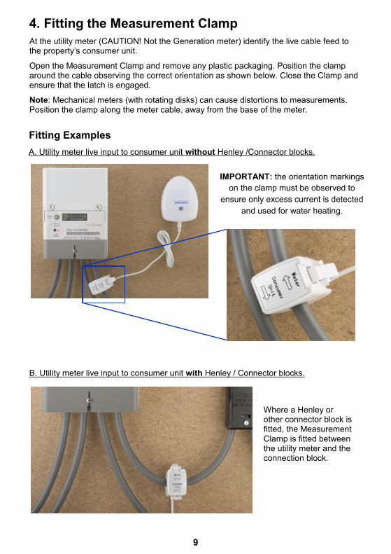
4. Fitting the Measurement Clamp
At the utility meter (CAUTION! Not the Generation meter) identify the live cable feed to the property’s consumer unit.
Open the Measurement Clamp and remove any plastic packaging. Position the clamp around the cable observing the correct orientation as shown below. Close the Clamp and ensure that the latch is engaged.
Note: Mechanical meters (with rotating disks) can cause distortions to measurements. Position the clamp along the meter cable, away from the base of the meter.
A. Utility meter live input to consumer unit without Henley /Connector blocks.
IMPORTANT: the orientation markings
on the clamp must be observed to
ensure only excess current is detected
and used for water heating.
B. Utility meter live input to consumer unit with Henley / Connector blocks.
Fitting Examples
Where a Henley or other connector block is fitted, the Measurement Clamp is fitted between the utility meter and the connection block.
10
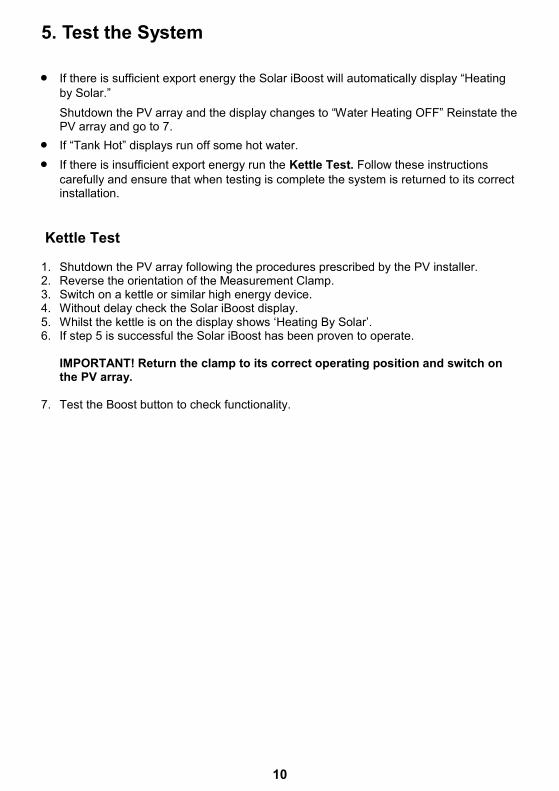
5. Test the System
Kettle Test 1. Shutdown the PV array following the procedures prescribed by the PV installer. 2. Reverse the orientation of the Measurement Clamp. 3. Switch on a kettle or similar high energy device. 4. Without delay check the Solar iBoost display. 5. Whilst the kettle is on the display shows ‘Heating By Solar’. 6. If step 5 is successful the Solar iBoost has been proven to operate. IMPORTANT! Return the clamp to its correct operating position and switch on
the PV array. 7. Test the Boost button to check functionality.
If there is sufficient export energy the Solar iBoost will automatically display “Heating
by Solar.”
Shutdown the PV array and the display changes to “Water Heating OFF” Reinstate the PV array and go to 7.
If “Tank Hot” displays run off some hot water.
If there is insufficient export energy run the Kettle Test. Follow these instructions
carefully and ensure that when testing is complete the system is returned to its correct installation.
11
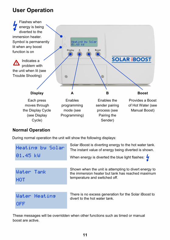
User Operation
Display
Each press
moves through
the Display Cycle
(see Display
Cycle)
B
Enables the
sender pairing
process (see
Pairing the
Sender)
A
Enables
programming
mode (see
Programming)
Boost
Provides a Boost
of Hot Water (see
Manual Boost)
Indicates a
problem with
the unit when lit (see
Trouble Shooting)
Normal Operation
Heating by Solar
01.45 kW
Water Tank
HOT
Water Heating
OFF
Solar iBoost is diverting energy to the hot water tank.
The instant value of energy being diverted is shown.
When energy is diverted the blue light flashes:
Shown when the unit is attempting to divert energy to the immersion heater but tank has reached maximum temperature and switched off.
Flashes when
energy is being
diverted to the
immersion heater.
Symbol is permanently
lit when any boost
function is on
These messages will be overridden when other functions such as timed or manual
boost are active.
!
During normal operation the unit will show the following displays:
There is no excess generation for the Solar iBoost to divert to the hot water tank.
12
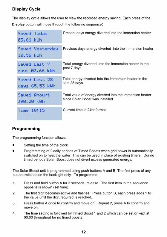
Display Cycle
The display cycle allows the user to view the recorded energy saving. Each press of the
Display button will move through the following sequence:
Saved Today
03.66 kWh
Saved Yesterday
10.56 kWh
Saved Last 7
days 03.66 kWh
Saved Last 28
days 65.53 kWh
Saved Amount
390.20 kWh
Time 10:15
Programming
The Solar iBoost unit is programmed using push buttons A and B. The first press of any button switches on the backlight only. To programme: 1. Press and hold button A for 3 seconds, release. The first item in the sequence
opposite is shown (set time).
2. The first digit becomes active and flashes. Press button B, each press adds 1 to the value until the digit required is reached.
3. Press button A once to confirm and move on. Repeat 2, press A to confirm and move on.
4. The time setting is followed by Timed Boost 1 and 2 which can be set or kept at 00:00 throughout for no timed boosts.
Present days energy diverted into the immersion heater
Previous days energy diverted into the immersion heater
Total energy diverted into the immersion heater in the past 7 days
Total energy diverted into the immersion heater in the past 28 days
Total value of energy diverted into the immersion heater since Solar iBoost was installed
Current time in 24hr format
The programming function allows:
Setting the time of the clock
Programming of 2 daily periods of Timed Boosts when grid power is automatically
switched on to heat the water. This can be used in place of existing timers. During timed periods Solar iBoost does not divert excess generated energy.
13
Set Time
10:15
Timed Boost 1
00:00 to 00:00
Timed Boost 2
00:00 to 00:00
Sets the internal clock time in hours and minutes.
Sets the Timed Boost for period 2 (e.g. evening). Operation
as per Timed Boost 1
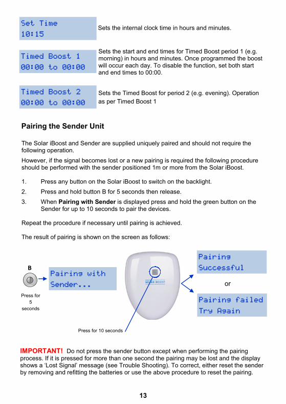
Pairing the Sender Unit
The Solar iBoost and Sender are supplied uniquely paired and should not require the following operation.
However, if the signal becomes lost or a new pairing is required the following procedure should be performed with the sender positioned 1m or more from the Solar iBoost. 1. Press any button on the Solar iBoost to switch on the backlight.
2. Press and hold button B for 5 seconds then release.
3. When Pairing with Sender is displayed press and hold the green button on the Sender for up to 10 seconds to pair the devices.
Repeat the procedure if necessary until pairing is achieved. The result of pairing is shown on the screen as follows:
Pairing with
Sender...
Pairing
Successful
Pairing failed
Try Again
IMPORTANT! Do not press the sender button except when performing the pairing
process. If it is pressed for more than one second the pairing may be lost and the display shows a ‘Lost Signal’ message (see Trouble Shooting). To correct, either reset the sender by removing and refitting the batteries or use the above procedure to reset the pairing.
Sets the start and end times for Timed Boost period 1 (e.g. morning) in hours and minutes. Once programmed the boost will occur each day. To disable the function, set both start and end times to 00:00.
B
Press for
5
seconds
or
Press for 10 seconds
14
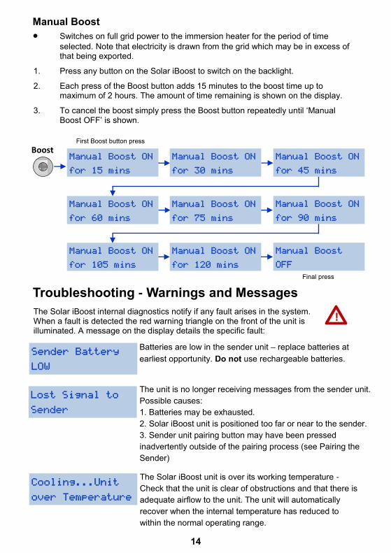
Manual Boost ON
for 60 mins
Manual Boost ON
for 120 mins
Manual Boost
OFF
Troubleshooting - Warnings and Messages
The Solar iBoost internal diagnostics notify if any fault arises in the system. When a fault is detected the red warning triangle on the front of the unit is illuminated. A message on the display details the specific fault:
Sender Battery
LOW
The unit is no longer receiving messages from the sender unit.
Possible causes:
1. Batteries may be exhausted.
2. Solar iBoost unit is positioned too far or near to the sender.
3. Sender unit pairing button may have been pressed
inadvertently outside of the pairing process (see Pairing the
Sender)
Lost Signal to
Sender
Cooling...Unit
over Temperature
Switches on full grid power to the immersion heater for the period of time
selected. Note that electricity is drawn from the grid which may be in excess of that being exported.
1. Press any button on the Solar iBoost to switch on the backlight.
2. Each press of the Boost button adds 15 minutes to the boost time up to maximum of 2 hours. The amount of time remaining is shown on the display.
3. To cancel the boost simply press the Boost button repeatedly until ‘Manual Boost OFF’ is shown.
Manual Boost
Boost Manual Boost ON
for 15 mins
Manual Boost ON
for 30 mins
Manual Boost ON
for 75 mins
Manual Boost ON
for 105 mins
Manual Boost ON
for 45 mins
Manual Boost ON
for 90 mins
First Boost button press
Final press
!
Batteries are low in the sender unit – replace batteries at
earliest opportunity. Do not use rechargeable batteries.
The Solar iBoost unit is over its working temperature -
Check that the unit is clear of obstructions and that there is
adequate airflow to the unit. The unit will automatically
recover when the internal temperature has reduced to
within the normal operating range.
15
Important Information about Legionella Legionella bacteria are common and can be found naturally in environmental water sources such as rivers, lakes and reservoirs, usually in low numbers. As legionella bacte-ria are commonly encountered they may eventually colonise manufactured water systems and if conditions are favourable the number of bacteria may grow. Contamination risks are however low due to the low availability of nutrients and the regular chlorination of the water supply. As with any hot water storage system it is important to avoid water stagnation and ensure the water is regularly heated to a minimum temperature of 55-60°C to reduce potential risks. It is therefore recommended that the hot water tank be heated to 55-60°C at least once per week either using Boost facility or through other heating controls.
Further Support
To find out more about how Solar iBoost works visit www.solariboost.co.uk Consult your qualified installer / electrician for any user queries. Technical support for qualified installers and electricians +44 (0) 1536 447866
Limited Warranty
The SIB Energy Company Limited Warranty provides free replacement cover for all defects in parts and workmanship for 24 months from the date of purchase. SIB Energy Ltd obligation in this respect is limited to replacing parts which have been promptly reported to the seller and are in the seller’s opinion defective and are so found by SIB Energy Ltd upon inspection. A valid proof of purchase is required if making a warranty claim.
Defective parts must be returned by prepaid post and accompanied by a Returns Authorisation available in advance from Marlec Engineering Company Limited, Rutland House, Trevithick Road, Corby, Northamptonshire, NN17 5XY, England, or to an authorised agent.
This Warranty is void in the event of improper installation, unauthorised service, use of unauthorised components, owner neglect, misuse or natural disasters including lightning strike. This warranty does not extend to ancillary equipment not supplied by the manufacturer. No responsibility is assumed for incidental damage. No responsibility is assumed for consequential damage.
SIB Energy Limited Peterborough
PE3 6SR
16
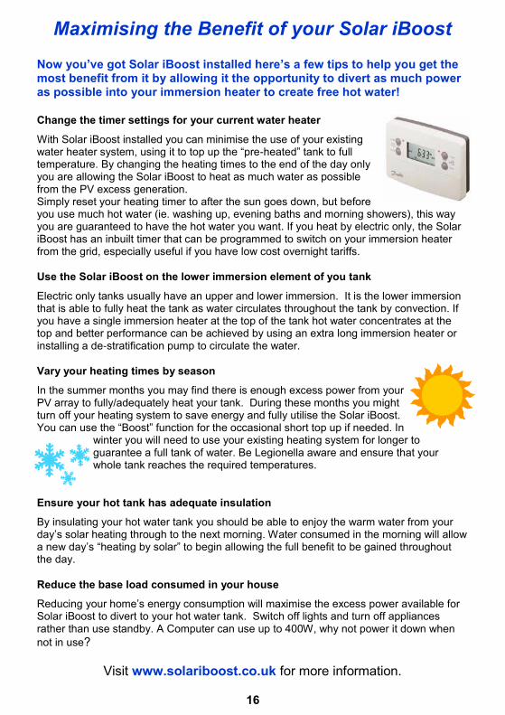
Maximising the Benefit of your Solar iBoost
Now you’ve got Solar iBoost installed here’s a few tips to help you get the most benefit from it by allowing it the opportunity to divert as much power as possible into your immersion heater to create free hot water!
Change the timer settings for your current water heater
With Solar iBoost installed you can minimise the use of your existing water heater system, using it to top up the “pre-heated” tank to full temperature. By changing the heating times to the end of the day only you are allowing the Solar iBoost to heat as much water as possible from the PV excess generation. Simply reset your heating timer to after the sun goes down, but before you use much hot water (ie. washing up, evening baths and morning showers), this way you are guaranteed to have the hot water you want. If you heat by electric only, the Solar iBoost has an inbuilt timer that can be programmed to switch on your immersion heater from the grid, especially useful if you have low cost overnight tariffs.
Use the Solar iBoost on the lower immersion element of you tank
Electric only tanks usually have an upper and lower immersion. It is the lower immersion that is able to fully heat the tank as water circulates throughout the tank by convection. If you have a single immersion heater at the top of the tank hot water concentrates at the top and better performance can be achieved by using an extra long immersion heater or installing a de-stratification pump to circulate the water.
Vary your heating times by season
In the summer months you may find there is enough excess power from your PV array to fully/adequately heat your tank. During these months you might turn off your heating system to save energy and fully utilise the Solar iBoost. You can use the “Boost” function for the occasional short top up if needed. In
winter you will need to use your existing heating system for longer to guarantee a full tank of water. Be Legionella aware and ensure that your whole tank reaches the required temperatures.
Ensure your hot tank has adequate insulation
By insulating your hot water tank you should be able to enjoy the warm water from your day’s solar heating through to the next morning. Water consumed in the morning will allow a new day’s “heating by solar” to begin allowing the full benefit to be gained throughout the day.
Reduce the base load consumed in your house
Reducing your home’s energy consumption will maximise the excess power available for Solar iBoost to divert to your hot water tank. Switch off lights and turn off appliances rather than use standby. A Computer can use up to 400W, why not power it down when
not in use?
Visit www.solariboost.co.uk for more information.