Embed Size (px)
Citation preview

Water Heater Manual Document 2105
Installationand OperatingInstructions for
NatcoFire Coil
MIGHTY
THERM
ModelsVW, PW and IWVolume Water Heaters
Sizes 500-1825
MIGHTY
THERM
FOR YOUR SAFETYDo not store or use gasoline or other flammable vapors and liquids in the vicinity of this or any other appliance.
WARNINGImproper installation, adjustment, alteration, service or maintenance can cause injury or property damage. Refer to thismanual. For assistance or additional information consult a qualified installer, service agency or the gas supplier.
FOR YOUR SAFETY - WHAT TO DO IF YOU SMELL GAS• Do not try to light any appliance.• Do not touch any electrical switch; do not use any phone in your building.• Immediately call your gas supplier from a neighbor’s telephone. Follow the gas suppplier’s information.• If you cannot reach your gas supplier, call the fire department.
These instructions are to be stored in the pocket provided on the boiler.
H21
0740
0-
NATCONATCO

Contents
SECTION 1. GENERAL INFORMATION Page
1A. Introduction ...................................................... 31B. Heater Identification ......................................... 31C. Flow Requirements .......................................... 41D. Water Chemistry .............................................. 4
SECTION 2. INSTALLATION
2A. Heater Placement ............................................ 42B. Installation of Indoor Heaters ........................... 5
2B-1 Combustion Air Supply ......................... 52B-2 Venting ................................................. 6
2C. Installation of Outdoor Heaters......................... 72D. Gas Supply and Piping ..................................... 72E. Electrical Wiring ............................................... 82F. Water Piping of System.................................... 92G. Water Expansion .............................................. 92H. Pump Performance and Installation ............... 102I. Water Pressure .............................................. 142J. Tank Installation ............................................. 142K. Two-Temperature System ............................. 17
SECTION 3. OPERATION
3A. Controls – General ......................................... 173B. Initial Start-up ................................................. 193C. To Start Up System........................................ 193D. To Turn Off Heater ......................................... 203E. To Shut Down System ................................... 20
SECTION 4. MAINTENANCE . ............................. 20
SECTION 5. TROUBLESHOOTING ANDANALYSIS OF SERVICE PROBLEMS . ................ 21
TABLES AND FIGURES
Table I. Boiler Configuration ................................. 4Table II. Minimum Recommended Air Supply
To Heater ................................................ 6
Table III. Gas Piping Sizes ..................................... 8Table IV. Pump Performance Requirements ........ 14Table V. Modu-snap Valve
Temperature Settings ............................ 18Figure 1 Boiler Configuration ............................... 3Figure 2 Typical Heater Installation with Base
for Combustible Floors (Ex. A) .............. 5Figure 3 Typical Heater Installation with Base
for Combustible Floors (Ex. B) .............. 5Figure 4 Typical Heater Installation with Base
for Combustible Floors (Ex. C) .............. 5Figure 5 Installation on Concrete Blocks
or Tile .................................................... 5Figure 6 Alcove Installation ................................. 6Figure 7 Incorrect Outdoor Installation ................ 7Figure 8 T-Fitting Sediment Trap Installation ....... 8Figure 9 Pressure Relief Valve Location ............. 9Figure 10 Tempering Valve Installation ................. 9Figure 11 Hot Water Supply System for
Models VW and PW ............................ 11Figure 12 Hot Water Supply System using
Model PW with Dual Tanks,Building Loop Return andCirculating Pump ................................. 12
Figure 13 Split System Piping for Model IW ........ 12Figure 14 Dual Installation Piping Diagram
for Model IW ........................................ 13Figure 15 Single Installation Piping
Diagram for Model IW ......................... 13Figure 16 Two Temperature Hot Water
Supply System (Model VW orPW) Vertical/Horizontal Tank .............. 15
Figure 17 Two Temperature Hot WaterSupply System w/VerticalTank for Models VW and PWWater Heaters ..................................... 16
Figure 18 Controls Location ................................ 16Figure 19 Control Components ........................... 18Figure 20 Pilot Burners (I.I.D.) ............................. 18Figure 21 Gas Manual Valves ............................. 19Figure 22 Pilot Safety Relay ................................ 20Figure 23 Main Burner Flame Pattern ................. 20

Section 1General Information1A. Introduction
This manual provides information for theinstallation and operation of Natco volume waterheaters. It is strongly recommended that allapplication and installation procedures be reviewedcompletely before proceeding with the installation.Consult the Natco factory, or local factoryrepresentative, with any problems or questionsregarding this equipment. Experience has shown thatmost problems are caused by improper installation.
Some accessory items are shipped in separatepackages. Verify receipt of all packages listed on thepackage slip. Inspect everything for possible damageupon delivery, and inform the carrier of any shortagesor impairments. Any such claims should be filed withthe carrier. The carrier, not the shipper, is responsiblefor shortages and damage to the shipment whethervisible or concealed.
IMPORTANT WARNING:
All volume water heaters must be installed inaccordance with the procedures outlined in thismanual. The warranty does not apply to heaters notinstalled or operated in accordance with theseprocedures. Consult local building and safety codesbefore proceeding with work. The installation mustconform to the requirements of the authority havingjurisdiction or, in the absence of such requirements, tothe latest edition of the National Fuel Gas Code;ANS1 Z223.1, National Electrical Code ANSI/NFPA70 and/or in Canada CAN1-B149 requirement.
3
Figure 1 – Boiler Configuration
When required by the authority having jurisdiction, theinstallation must conform to American Society ofMechanical Engineers safety codes for controls andsafety devices for automatically fired heaters No.CSD-1, and in Canada CGA 3.3. Any modification tothe water heater, its gas controls, gas orifices, wiringor draft diverter may void the Natco warranty. If fieldconditions require such modifications, consult factory.
1B. Heater Identification
Consult rating plate on the heater. The followingexample simplifies the heater identification.
1 2 3 4 5 6
P W 1 6 7 0 I N 09 L
(1) Basic heater model.*(2) Input rate X 1000 BTU/hr.(3) Indoor (I) or Outdoor (E) installation.(4) Gas type: Natural (N) or Propane (P).(5) Ignition system: I.I.D. (09) or continuous pilot
(16).**(6) Firing rate: On/Off (C), 2-stage (K), 4-stage (L),
or Mech. Mod (H).
*Model VW water heaters for use with separatestorage tank. There must be a field installed pump tocirculate water between the heater and the storagetank.
*Model PW water heaters are basically the same asthe VW series except that the PW heaters come withintegrally mount pumps.
*Model IW water heaters are tankless instantaneousheaters, complete with mount pump for use inapplications having a suitable diversity in heater load.
**Special Options: I.I.D. (04) 115 volts or I.I.D. (08)IRI Controls
Natco commercial water heaters are available intwo models: an indoor version and an outdoorversion. Both are available from the factory. SeeFigure 1.

Section 2Installation2A. Heater Placement
The heater must be placed to provide specificclearances on all sides for maintenance andinspection. There must also be minimum distancesmaintained from combustible surfaces. Theseclearances also apply to non-combustible materialsbecause the heater requires air circulation for properoperation.
Table I. Minimum Boiler ClearancesFrom Combustible Surfaces
Clearance Indoor Outdoor From (Inches) (Inches)
Top 30 unobstruct
Water Conn Side 12 24
Opposite Side 6 24
Front Alcove unobstruct
Rear 8 24
Vent Pipe* 6 --
Hot Water Pipes Per Code Per Code
*Using type B Vent (refer to Manufacturer’s Instructions)
Heater should be mounted on a level surface. Anintegral combustible flooring base is provided asstandard equipment on outdoor models. Indoormodels can be installed on a combustible floor with aspecial base assembly which is available from thefactory. See rating plate for part number of the baseassembly.
Do not install a heater on carpeting.
Under the National Fuel Gas Code, ANSI Z223.1,it is permissible to place the heater on floors otherthan non-combustible when the installation complieswith the American Insurance Code. Figures 2, 3, 4and 5 show common installation on combustibleflooring.
1C. Flow Requirements
For proper operation, all low volume hot waterheaters must have continuous flow through the heatexchanger when firing. The system pump must becapable of developing sufficient pressure to overcomethe resistance of the heater plus the entire circulatingsystem at the designed flow rate.
1D. Water Chemistry
Natco equipment is designed for use in a widevariety of water conditions. The water velocitymaintained in the heat exchanger tubes is kept highenough to prevent scaling from hard water and lowenough to avoid corrosion from soft water. Ninety-fivepercent of the urban areas in the country have waterthat is compatible with this equipment, but in someareas a water supply will contain a large quantity ofscaling chemicals or the water may be extremely softand corrosive. In rare situations the water will containboth scaling chemicals and corrosive chemicals suchas calcium or sodium chloride. These conditions maybe the result of a nearby well or pumping station andthe particular condition may not be characteristic ofthe entire city water system.
If an installer observes damage from theseconditions to any water handling equipment in thearea, a factory representative should be contactedimmediately for assistance in minimizing maintenancecosts. If erosion is present, the pump impeller can bereplaced to reduce water velocity. If scalingconditions are bad, tube cleaning maintenanceschedules can be established to prevent tube burn-out and cracking. Neglecting the problem could meanserious damage to the heater and water system.
Scaling can be recognized as a layer depositedon the inner walls of the tube which reduces the innerdiameter of the tube. Scale can be any color ortexture; smooth or rough, granular or amorphous.Signs of erosion are generally pitting, cavitation,ridges and “islands” on the inner walls of the tubes.Since this condition results from extremely soft watersources, or as a result of a water softening program,the internal copper surfaces will be extremely shiny.Other chemicals, such as chlorine or chlorides in thewater, will cause dark surfaces of erosion.
In areas where the water supply is extremelycorrosive, it is advisable to order the heater withcupro-nickel tubes in the exchanger.
Damage From Scaling, Corrosion, or Erosion isNot Covered by the Warranty.
4

Figure 5 – Installation on Concrete Blocks or Tile
Figure 2 – Typical Heater Installation with Base forCombustible Floors, Example A
Figure 3 – Typical Heater Installation with Base forCombustible Floors, Example B
Figure 4 – Typical Heater Installation with Base forCombustible Floors, Example C
5
2B. Installation of Indoor Heaters
1. Locate the water heater to provide adequateclearance for inspection and service on all sides.See Table I. We recommend minimums of24" from front (for proper access to andservice of controls) and 18" at water connectionend. For alcove installation, see Figure 6.
2. Install the heater on a waterproof floor with anadequate floor drain and a 6" minimum curb onall four sides to protect the building if heaterrepairs are required. The manufacturer will notbe held liable for any water damage inconnection with this heater.
2B-1. Combustion Air Supply
1. The heater location must provide sufficient airsupply for proper combustion and ventilation ofthe surrounding area as outlined in the latestedition of ANSI standard Z223.1, and any localcodes that may be applicable. Inadequatecombustion air supply may result in incompletecombustion, sooting of the heat exchanger, andunsafe operation of the heater.
2. In general, these requirements specify thatsmall heater rooms should beprovided with two permanentair supply openings communicatingdirectly through the wall to outside air; one within
Base For Combustible Floors
Concrete Slab - 4" Minimum
Concrete Slab Must Extend Out A Minimum Of 12" On All Sides
Roof - Wood & Steel Construction
Unit(End View)
UnitBase
Add Base for Combustible Floors on Indoor Units.Base Comes Standard on Outdoor Units.
Base For Combustible Floors
Raised Mounting Platform (Wood)
Mounting Platform Must Extend Out A Minimum Of 12" On All Sides
Unit(End View)
UnitBase
20 GA Galvanized Sheet Metal Cap
Flashing
RoofRoof
Add Base for Combustible Floors on Indoor Units.Base Comes Standard on Outdoor Units.
Unit(Front View)
20 GA Galvanized Sheet Metal Cap
Flashing
RoofRoofing
4X4 Stringer
Base Rail
Base for Combustible Floors
Base Must Extend OutMin. 12" On All SidesOf Heater Frame
Metal Plate 20 Ga. Min.Under Entire Heater
Concrete Blocks Or TileMin. 7" High With 3" Min.Air Openings
Blocks must provide solid base and be braced so they cannot slip out of place. Air openings in blocks must be arranged to provide unobstructed opening through entire width or length of base.

12 inches of the ceiling, and the other within 12inches of the floor. Each opening shouldhave a minimum free area of one square inch per4,000 BTUH input of the total input rating of allappliances in the enclosed area. See Table II forrecommended air supply for each model. Animproperly ventilated equipment room can getexcessively hot and cause accelerateddeterioration of controls and electricalcomponents.
IMPORTANT: In beauty shops, barber shops,cleaning establishments and self-service laundrieswith dry cleaning equipment, it is important that thewater heater be installed in a location wherecombustion and ventilation air is received from asource outside the building. Please refer to the mostrecent edition of the National Fuel Gas Code, ANSI
* When the ceiling height exceeds 8 feet, you are only allowed to consider 8feet when calculating the total volume of the enclosure.
Z223.1, or in Canada, CGA requirements.
3. Exhaust Fans or Vents: Any equipment whichexhausts air from the heater room can depletethe combustion air supply or reverse the naturaldraft action of the venting system. This couldcause flue products to accumulate in the heaterroom. Additional air must be supplied tocompensate for such exhaust. The information inTable II is not applicable in installations whereexhaust fans or blowers of any type are used.Such installations must be designed by
qualified engineers.4. If a blower or fan is used to supply air to the
heater room, the installer should make sure itdoes not create drafts which could causenuisance shutdowns of the pilot. If a blower isnecessary to provide adequate combustion air tothe heater, a suitable switch or equivalent mustbe wired into the heater control circuit to preventthe heater from firing unless the blower isoperating.
5. The heater must be completely isolated andprotected from any source of corrosive chemicalfumes such as trichlorethylene, perchlorethylene,chlorine, etc.
Table II. Minimum RecommendedAir Supply to Heater
Heater Each Opening* Model (Square Inches)
500 125600 150715 179850 2131010 2531200 3001430 3581670 4181825 457
*Net Free Area in Square Inches
Area indicated is for one of two openings; one atfloor level and one at the ceiling, so the total net freearea could be double the figures indicated. Forspecial conditions refer to the latest edition of ANSIZ223.1 or, in Canada, CAN1-B149.1 and .2.
Consult factory if not communicating directly throughthe walls with the outdoors.
Note: Check with louver manufacturers for net freearea of louvers. Correct for screen resistance to thenet free area if a screen is installed. Check all localcodes applicable to combustion air.
2B-2. Venting
1. Natco heaters have built-in draft diverters fornatural draft operation and must not beconnected to any portion of a mechanicaldraft system under positive pressure. The flueoutlet must be connected to a clear, unobstructedvent of adequate capacity ending above the
6
123456789012345678901234567890123456789012345678901234567890123456789012345678901234567890123456789012345678901234567890123456789012345678901234567890123456789012345678901234567890123456789012345678901234567890123456789012345678901234567890123456789012345678901234567890123456789012345678901234567890
WaterHeater
12345678901234567890123456789012345678901234567890123456789012345678901234567890123456789012345678901234567890123456789012345678901234567890123456789012345678901234567890123456789012345678901234567890123456789012345678901234567890123456789012345678901234567890123456789012345678901234567890123456789012345678901234567890
CLOSET INSTALLATION(UNACCEPTABLE)
A closet is any 4 sided enclosurewhich is less than 16* times the totalvolume of all the gas fired applianceswithin the enclosure.
ROOM INSTALLATION(ACCEPTABLE)
A room is any enclosure which is atleast 16* times greater than the totalvolume of all the gas fired applianceswithin the enclosure.
123456789012345678901234567890123456789012345678901234567890123456789012345678901234567890123456789012345678901234567890123456789012345678901234567890123456789012345678901234567890123456789012345678901234567890123456789012345678901234567890123456789012345678901234567890123456789012345678901234567890
WaterHeater
Figure 6 – Alcove Installation
ALCOVE INSTALLATION(ACCEPTABLE)
An alcove suitable for the installationof a water heater is a restricted sectionof a room not separated from theroom by a door or partition and whichmeets the minimum clearances forthe specific model water heater listedbelow.

7
Figure 7 – Incorrect Outdoor Installation
WindowOr Grill
IndoorRoom
WRONG
highest point of the building with an approvedvent cap. The venting system should be installedaccording to the latest edition of ANSI Z223.1and/or, in Canada, CAN1-B149 requirement andany local codes having jurisdiction.
IMPORTANT NOTE: Do not use sheet metal screwsat the snap lock joints of Type B gas vents.
2. Do not weld or fasten the vent pipe to the heaterdraft hood. The weight of the stack must not reston the heater. The draft hood and heater topmust be easily removable for normal heaterservice and inspection.
3. Avoid using long horizontal runs of the vent pipe,and too many 90° elbows, reductions orrestrictions. Horizontal runs should have at leasta 1/4" rise per foot in the direction of flow. A ventconnector should be supported for the design andweight of the material used to maintainclearances and prevent physical damage andseparation of joints.
4. Avoid ending heater vents near air conditioning orair supply fans. The fans can pick up exhaustflue products from the heater and return theminside the building, creating a possible healthhazard. A minimum of 4 feet horizontal distancemust be maintained from electrical meters, gasmeters, and relief equipment.
5. Always use double-wall or insulated vent pipe(Type B or equivalent). In cold weather,uninsulated outside vents can chill the rising flueproducts, blocking the natural draft action of theventing system. This can create a health hazardby spilling flue products into the heater room.
6. Avoid oversize vent piping or extremely long runsof the pipe which may cause excessive coolingand condensation. Rule of Thumb: The totallength of the vent, including the connector andany offset, should not exceed 15 feet for everyinch of vent diameter. Longer total lengthsshown in venting tables are based on maximumcapacity, not condensation factors.
7. When the installation of a draft fan is necessaryin connecting a venting system to a Natcoheater, the installation should be engineeredby competent personnel following goodengineering practices. The draft fansupplier should be consulted for correct size.The installation should be in accordance with thelatest edition of ANSI Z223.1 and/or, in Canada,CAN1-B149 requirement and any local codeshaving jurisdiction. When a draft fan is installed,
a suitable draft switch must be wired into theheater control circuit at terminal designated “FieldInterlock” to prevent firing of the heater unless apositive draft has been established.
2C. Installation of Outdoor Heaters
1. Locate the heater to provide the minimumclearances as listed in Table I, “Placement ofHeater”.
2. Do not place the heater in an enclosure or wallrecess. Avoid locations where wind deflection offstructures might cause down draft. When suchwind conditions are possible, place the heater atleast three (3) feet from the structures.
3. Never install the heater under any kind of roofoverhang. Do not place the heater below oradjacent to any doors, windows, louvers, grills,etc. which connect in any way with an inhabitedarea of a building. This includes other structuressuch as garages or utility rooms (see Figure 7 ).
4. Although these models are AGA and CGAdesigned certified for outdoor installations, suchinstallations are not recommended in areaswhere the danger of freezing exists unless properprecautions are taken for freeze protection.
2D. Gas Supply and Piping
Review the following instructions before proceedingwith the installation.
1. Verify that the heater is fitted for the proper typeof gas by checking the rating plate. Natco heatersare normally equipped to operate below a 2000foot altitude. Heaters equipped to operate athigher altitudes have appropriate stickers or tags
attached.2. Use the figures in Table III to provide adequate
gas piping from the gas meter to the heater.
Table III. Gas Piping Sizes
Distance from Gas Meter or Last Stage Regulator
Model 0-100' 100-200' 200-300'
500 1-1/2" 2" 2"600 1-1/2" 2" 2-1/2"715 2" 2" 2-1/2"850 2" 2-1/2" 2-1/2"1010 2" 2-1/2" 3"1200 2-1/2" 3" 3"1430 2-1/2" 3" 3"1670 2-1/2" 3" 3"1825 2-1/2" 3" 3-1/2"
Note: These figures are for Natural Gas (.65 Sp.Gr.), and are based on 1/2" water column pressuredrop. Check supply pressure with a manometer, andlocal code requirements for variations. For LPG,reduce pipe diameter one size, but maintain a 1"minimum diameter. A normal number of Tees andelbows have been taken into allowance.
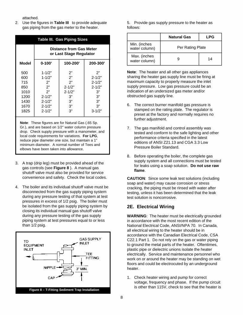
3. A trap (drip leg) must be provided ahead of thegas controls (see Figure 8 ). A manual gasshutoff valve must also be provided for serviceconvenience and safety. Check the local codes.
4. The boiler and its individual shutoff valve must bedisconnected from the gas supply piping systemduring any pressure testing of that system at testpressures in excess of 1/2 psig. The boiler mustbe isolated from the gas supply piping system byclosing its individual manual gas shutoff valveduring any pressure testing of the gas supplypiping system at test pressures equal to or lessthan 1/2 psig.
5. Provide gas supply pressure to the heater asfollows:
Natural Gas LPG
Min. (inches water column)
Max. (inches water column)
Note: The heater and all other gas appliancessharing the heater gas supply line must be firing atmaximum capacity to properly measure the inletsupply pressure. Low gas pressure could be anindication of an undersized gas meter and/orobstructed gas supply line.
6. The correct burner manifold gas pressure isstamped on the rating plate. The regulator ispreset at the factory and normally requires nofurther adjustment.
7. The gas manifold and control assembly wastested and conform to the safe lighting and otherperformance criteria specified in the latesteditions of ANSI Z21.13 and CGA 3.3 LowPressure Boiler Standard.
8. Before operating the boiler, the complete gassupply system and all connections must be testedfor leaks using a soap solution. Do not use rawflame.
CAUTION: Since some leak test solutions (includingsoap and water) may cause corrosion or stresscracking, the piping must be rinsed with water aftertesting, unless it has been determined that the leaktest solution is noncorrosive.
2E. Electrical Wiring
WARNING: The heater must be electrically groundedin accordance with the most recent edition of theNational Electrical Code, ANSI/NPA 70. In Canada,all electrical wiring to the heater should be inaccordance with the Canadian Electrical Code, CSAC22.1 Part 1. Do not rely on the gas or water pipingto ground the metal parts of the heater. Oftentimes,plastic pipe or dielectric unions isolate the heaterelectrically. Service and maintenance personnel whowork on or around the heater may be standing on wetfloors and could be electrocuted by an undergroundheater.
1. Check heater wiring and pump for correctvoltage, frequency and phase. If the pump circuitis other than 115V, check to see that the heater is
8
Figure 8 – T-Fitting Sediment Trap Installation
Per Rating Plate
9 14

provided with an appropriate transformer.2. Wire the heater and pump exactly as shown in
the wiring diagram supplied with the heater.
3. The pump and heater must be electricallyinterlocked so the heater cannot come on unlessthe pump is running.
4. All field installed electrical safety devices and allfield installed devices (draft switches, relays,timers, outdoor temperature reset devices, etc.)can be connected to the heater wiring at pointsshown in the wiring diagram designated “FieldInterlock”.
2F. Water Piping of System
1. Be sure to provide valves at the inlet and outlet ofthe boiler so it can be readily isolated for service.A butterfly or similar type of valve isrecommended.
2. The pressure relief valve installed in the tappedopening provided in the outlet header (SeeFigure 9), must be piped, but not fastened, to adrain or floor sink. The drain pipe must be thesame size as the valve outlet and must pitchdownward from the valve.
Special attention must be given to relief valvesettings in installations where the heater islocated on the ground floor of a tall building. Thestatic pressure of the system is elevated andcould cause the relief valve to leak. Where nospecial setting of the relief valve is ordered, thefactory will furnish a 125 psi setting. Neverreduce the relief valve openings.
Figure 10 – Tempering Valve Installation
9
Figure 9 – Pressure Relief Valve Location
PressureReliefValve
Hot Water
Hot WaterStorageTank
Floor
AutomaticTemperingValve
Cold Water
Tempered Water
24"
3. Pressure relief valve lever must be tripped atleast once a year to insure that waterways areclean. When manually operating lever, water willdischarge through drain line. Precautions must betaken to avoid contact with hot water and waterdamage.
4. The weight of all water and gas piping should besupported by suitable hangers or floor stands.
5. Check piping diagrams with local applicableplumbing, heating and building safety codes.
6. All two-temperature systems using temperaturevalves must have forced recirculation in the lowtemperature building loop.
7. A check valve installed at the hot water inlet tothe tempering valve will prevent cold water frombeing drawn in reverse through the temperingvalve into the hot water.
8. When installing a tempering valve, place atbottom of antithermosyphon loop at least 24" highto prevent excessive hot water from enteringmixed water supply. Bring the cold water supplyup from the floor to the valve. (See Figure 10)
2G. Water Expansion
When cold water is heated the water expands. Ifno water is being used during the heat-up period theexpanded water will normally back up into the citymains.
A water pressure reducing valve installed in theincoming cold water line may act as a check valveand prevent the expanded water from movingbackward. This will cause pressure to rise in theheater, which will be relieved by the pressure reliefvalve.
If the relief valve pops frequently a mineraldeposit may build up on the valve seat, causing it to

leak.The following suggestions may solve the problem:
1. Replace the installed water pressure reducingvalve with a suitable valve having a back flowport. These valves have a back flow port whichallows water to flow backwards when thepressure in the system exceeds the pressure inthe mains.
2. Install a check valve around the pressurereducing valve to permit reverse flow. This willallow the expanded water to back flow into themains.
3. Install an auxiliary small relief valve set at 25 psiless than the main relief valve. The valve mustbe piped to a drain and may require occasionalcleaning. It will bleed off the expanded water andprotect the main pressure relief valve frombecoming fouled.
4. Install a properly sized expansion tank.
2H. Pump Performance and Installation
1. The factory provided pump on PW heaters andthe recommended field provided pump for modelVW heaters are sized to provide propercirculation through the heater and heater-to-tankcirculation loop (see Figure 11 and 12 ). If theheater-to-tank circulating loop does not containmore than 6 elbows or 30 feet of pipe, usepipe fittings in the loop no smaller than thefollowing:
Model Pipe Size
500 through 850 2" 1010 through 1825 2-1/2"
If the heater-to-tank circulating loop containsmore than 6 elbows or 30 feet of pipe, usepipe or fittings in the loop no smaller than thefollowing:
To Building
Model Pipe Size
500 through 850 2-1/2"1010 through 1825 3"
To assure free circulation, do not use globevalves, side outlet tee connections or otherrestrictive fittings in heater-to-tank loop.
2. The Model IW heater is designed for use in asystem without a hot water storage tank. The hotwater supply line to usage point must have areturn leg to the heater (see Figure13, 14 and15). A built-in circulating pump and internal heatexchanger bypass maintains the heater in astandby condition. It also maintains thetemperature at the controller setting of the waterin the entire building circulating loop whether ornot there is any use of hot water.
A separate circulating pump is required forcirculation of water in the building loop. Thecontrol system provides variable heat inputs tomatch periods of higher or lower waterconsumption.
3. The Model IW heater requires a minimum ofcirculating hot water in the building circulationloop. To prevent excessive temperaturefluctuations in the delivered water, the wholebuilding system, including the return loop, musthave the equivalent volume of pipe shown below:
Minimum Reservoir Equivalent PipeModel IW Gallons* Size and Length
500 through 850 .............. 6.3 ................. 1 1/4" x 100 ft.1010 through 1220 ........ 10.2 ................. 1 1/2" x 100 ft.1430 through 1670 ........ 17.0 ....................... 2" x 100 ft.1825 ............................... 27.0 ................. 2 1/2" x 100 ft.
* The gallons shown are the calculated volumes of the pipes.
4. Model VW, PW and IW heaters are not suitablefor heating swimming pools or any otherapplication where temperature of the waterflowing through the heater remains below thedew point (110F).
In applications requiring the rapid use ofmeasured volumes of water, the recovery of theheater between the time intervals of use mustequal the volume used. See the recovery table inthe current Document 2045 (Submittal Data).
10
PressureReducingValve
WaterSupply Check
Valve

11
Figure 11 – Hot Water Supply System (Model VW & PW)
NOTES:
Heavy line indicates Heater to Tank Circulating Loop.
WithHorizontalTank
WithVerticalTank
ColdWater
Bldg.LoopCirc.Pump
CheckValve
ThrottlingValve
HotWaterTo Bldg.
ConventionalTank
To Drain
To Drain
To Drain
PumpPW SeriesVW Series
Optional Cold Water Supply When Adequate Tank Opening Not Available
ServiceValves
Hot WaterReturn FromBldg.
ColdWater
Bldg.LoopCirc.Pump
HotWaterTo Bldg.
ConventionalTank
Drain
HotWaterStorageTank
24" Min.
ServiceValves
To Drain
To Drain
PumpPW SeriesVW Series

12
Figure 13 – Split System Piping Diagram, Model IW
Figure 12 –Hot Water Supply System Using Model PW with Dual Tanks, Building Loop Return and Circulating Pump
NOTES:1. Heavy line indicates Heater to Tank Circulating Loop.2. When a very large volume of water is circulated in the building loop with the use of a separate pump, tee building loop into cold water
supply and return to storage tank.
CAUTION:1. This piping arrangement is required on split systems to provide constant hot water temperatures.2. Pipe size and length must conform to the recommendations for each heater model.3. A loop circulator is required to maintain forced circulation in the building hot water piping system.
ColdWaterSupply
Return Loop Pump (see note 2)
CheckValve
To Drain
ConventionalTank
To Drain
To Drain
Recommended Increasing One Pipe Size From C.W. Connection To Tanks
Optional Cold Water Supply When Adequate Tank Opening Not Available
Service Valves
Pressure Relief Valve
Service Valve
Hot Water Return From Building
Hot Water To Building
Service Valve
ConventionalTank
Gas Supply
Flow Switch -Factory Mountedand Wired
Drain Valve
Cold WaterSupply
Check Valve
Building LoopCirculator(See Note 3)
Service Valves For*Heater Isolation
To Building ServiceConnections
Model IW Water Heater
Building LoopCirculator(See Note 3)
*This Section Of Piping Must Be Same Size As Water Heater Connection
Building LoopMinimum Pipe Size 1" Thru 8501-1/4" 1010 Thru 1825
PressureReliefValve
Check Valve

13
Figure 15 – Single Installation Piping Diagram, Model IW
Figure 14 – Dual Installation Piping Diagram, Model IW
NOTES:1. All water connections 2" N.P.T. models.2. Drain valve per ASME requirements.3. A loop circulator is required to maintain forced circulation in the building hot water piping system.
NOTES:1. All water connections 2" N.P.T. models.2. Drain valve per ASME requirements.3. A loop circulator is required to maintain forced circulation in the building hot water piping system.
Gas Supply
Flow Switch -Factory Mountedand Wired
Drain Valve(See Note 2)
Cold WaterSupply Building Loop
To BuildingServiceConnections
Building LoopCirculator(See Note 3)
Building LoopTo MinimumPipe Size1" Thru 8501-1/4" 1010 Thru 1825
Service Valves ForHeater Isolation
Available In StageOr Modulated Firing
Model IW Water HeaterThis Seqment Of Piping Must Be Same Size As Water Heater Connection
*
*
Service Valves ForHeater Isolation
ToDrain
ToDrain
Gas Supply
Flow Switch -Factory Mountedand Wired
Drain Valve(See Note 2)
Cold WaterSupply Check Valve Building Loop
To BuildingServiceConnections
Building LoopCirculator(See Note 3)
Check Valve
Service Valves ForHeater Isolation
Available In StageOr Modulated Firing
Model IW Water Heater
This Seqment Of Piping Must Be Same Size As Water Heater Connection
*
*

5. Pump Sizing: A suitable pump must be field-provided for circulation of water between ModelVW heaters and the storage tank. This pumpmust be sized to avoid excessive temperaturerise and to provide correct flow for waterhardness conditions. Specifications in Table IVinclude allowance for 30 feet of piping and normalfittings between heater and tank.
6. Install pump in a cool location. When pump isinstalled where it is subjected to excessive heat,the life of the pump will be shortened. Heat willembrittle motor insulation and dry out bearinglubricants. If the pump motor is equipped withthermal protection, excessive heat may trip thethermal switch and shut down the pump 2J.
intermittently. This could result in rapid scaling ofthe heater.
IMPORTANT: Check oil level in pump before starting.Oil pump every three (3) months. Fill bearingassembly to lower level of overflow vent. Add five (5)or six (6) drops of oil to front and rear of motor. Use20W non-detergent oil. Pumps located in excessivelyhot or dusty locations should be oiled once a month.Self lubricating pumps do not require oiling.
7. The pump should be accessible for lubrication,inspection and service.
8. If pump is designed for floor mounting, installsecurely on concrete block or pad at least six (6)inches above floor level. This will preventflooding of motor when floor is washed. Be surethat floor mounted pumps are not suspendedfrom piping and that piping is plumbed to avoidstrain on the pump casing.
2I. Water Pressure
It is very important that water pressure in thesystem be maintained above 30 psi. If thesystem pressure should drop below this, thevapor pressure of water in the suction side of thepump can cause hammer and cavitation in thepump and damage the heater through lack ofwater circulation. If for any reason the watersupply is turned off temporarily to service apiece of equipment, the manual gas valve onthe Model IW should be closed until the waterpressure has been restored and the lines bled ofaccumulated air. If the heater fails to fire when itis turned back on, it may be airlocked. Toeliminate the airlock, open the pressure reliefvalve and allow air to bleed out until water flows.As soon as full circulation is resumed, theentrained air will be carried out through the hotwater faucets.
2J. Tank Installation
1. Be sure the floor is waterproof and structurallycapable of supporting the tank when it is filledwith water.
2. The tank should be placed so that manholes,inspection covers, nameplates and drain valvesare accessible.
3. Be sure the tank is suitable for the water in thesystem. Some water is corrosive and requires aprotected tank with a special lining.
14
Table IV. Pump Performance Requirements
Flow Head* Temp. Rise Water Rate Loss Across
Model Category (GPM) (ft.) Heater, (F)
Soft 45 5.0 17500 Normal 68 9.9 11
Hard 90 15.7 8
Soft 45 5.1 20600 Normal 68 10.0 14
Hard 90 15.9 10
Soft 45 5.3 24715 Normal 68 11.0 16
Hard 90 17.8 12
Soft 45 5.4 30850 Normal 68 11.1 20
Hard 90 18.1 15
Soft 45 3.9 351010 Normal 68 7.5 23
Hard 90 11.7 18
Soft** 68 7.8 271200 Normal 68 7.8 27
Hard 90 12.2 21
Soft** 68 8.1 321430 Normal 68 8.1 32
Hard 90 12.6 24
Soft** 68 8.3 371670 Normal 68 8.3 37
Hard 90 13.0 28
Soft** 90 13.5 301825 Normal** 90 13.5 30
Hard 90 13.5 30
Water Category Grain Hardness per Gal. Soft 1 through 7.5 Normal 7.6 through 17 Hard Over 17
* Pressure drop includes loss through 30 feet of pipe and normal fittingswhen heater is installed with storage tank. Pipe and fittings are assumed tobe 2" on Models (500-850) and 2 1/2" on Models (1010-1825)
** To prevent erosion, these models must be ordered with cupro-nickel heatexchanger tubes.

2K. Two-Temperature System
See Figure 16 and Figure 17 for pipingschematic. This system is designed to maintainthe tempered water circulating loop at the desiredtemperature during idle periods as well as whenthere is a demand for hot water. It isrecommended for general purpose water supplyincluding shower and bathing applications.water at 180F is available directly from the tank.
Section 3Operation
3A. Controls - General
1. Electronic Ignition Controls:
a. Intermittent Ignition:
Pilots are automatically lit when the operatingaquastat calls for heat (System #4 and #9)
17
Figure 18 – Controls Location
The unit performs its own safety check andopens the main valves only after the pilot isproven to be lit. Whenever the pilot flame isinterrupted, the main gas valve closes within8/10 of a second.
b. Electronically Supervised Standing PilotSystem (System #16):
When pilot flame fails, the ignition controlmodule responds in less than 0.8 secondsand provides 100% safety shutdown.
2. Operating Controls:
a. Electrically Operating Controls:
Single, two-stage, four-stage or modulatingaquastats are provided in models VW, PWand IW heaters to control the desired servicewater tempera-ture. The temperaturesensing bulb is located either in the heaterinlet or outlet header.
b. Modu-snap Valves:
These valves are furnished in addition to themain electric gas valve (standard on model
Rating Plate
Ignition Control Pressure Relief Valve
Flow Switch
Transformer
Terminal Strip
Operating Control (Aquastat)
Hi-LimitOperating Gas Valve
Manual Pilot Valve
Manual Main Gas Valve
Safety Gas Valve
In
Out

15
Figure 16 – Two-Temperature Hot Water Supply System (Model VW or PW)
LegendB – Check Valve in Hot Water Supply toTempering ValveC – Check Valve in Return Line from Building LoopD – Tempering ValveE – Venturi (Suction) TeeH – Throttling Valves in Building Loop ReturnsI – Circulating Pump for 180° Building LoopJ – Circulating Pump for 140° Building LoopK – Service Valves to isolate Heater and Pump forService
LegendB – Check Valve in Hot Water Supply toTempering ValveC – Check Valve in Return Line from Building LoopD – Tempering ValveE – Venturi (Suction) TeeH – Throttling Valves in Building Loop ReturnsI – Circulating Pump for 180° Building LoopJ – Circulating Pump for 140° Building LoopK – Service Valves to isolate Heater and Pump forService
WithHorizontalTank
WithVerticalTank
ColdWater
180°WaterTo Bldg.
ConventionalTank
To Drain
24" Min.
To Drain
PumpPPW SeriesPVW Series
H
140°WaterTo Bldg.
140° WaterReturnFrom Bldg.
180° WaterReturnFrom Bldg.
H
C
C
BD
I
K
K
E
J
ColdWater
180°WaterTo Bldg.
ConventionalTank
To Drain
140°WaterTo Bldg.
To Drain
PumpPW SeriesVW Series
180°WaterReturn
From Bldg.
140°WaterReturn
From Bldg.
B
D
E
K
C
HC
H
J
I

C
D
B
K
J
C
H C
H
J180°FWaterToBldg.
Conventional Tank
140°F WaterTo Bldg.
ToDrain
To Drain
Cold Water
ToDrain
PumpPW SeriesVW Series
140°F WaterReturn From
Bldg.
180°F WaterReturn From
Bldg.
Cold Water
PumpPW SeriesVW Series
16
Figure 17 – Two-Temperature Hot Water Supply System with Vertical Tank for Models VW and PW Water Heaters
recommended pipe size, a larger pump may berequired. Consult the factory if in doubt.
6. Install a pipe in the tank drain fitting that goes to afloor sink, and install a drain valve. If a floor sinkis not available, install a hose bib.
7. Hot water tanks in an existing installation arelikely to have a deposit of silt on the bottom.Therefore, it is important to extend the pumpsuction pipe in the tank to a position near the top.Pipe the return from the heater to the bottom ofthe tank.
4. If the tank is glass-lined, it should be equippedwith a suitable magnesium anode. It is goodpractice to replace the anode when it isapproximately 50% used. The factory warrantyon a glass-lined tank will be void if a satisfactoryanode is not in place at the time of a failure or if itis consumed by cathodic action.
5. Make sure the tank connections in the heater-tank circulating loop are the proper size as listedin Section 2H. If tappings are smaller than the
LEGENDB – Check ValveC – Check ValveD – Tempering ValveH – Throttling Valves in Building Loop ReturnsJ – Circulating Pump for Return LoopK –Service Valves to Isolate Heater and Pump for Service

Dial No. 1 2 3 4 5 6 7 8 9+
Temp °F 120 128 135 143 150 158 165 173 180+
18
Figure 20 – Pilot Burners (I.I.D.)
Table V – Modu-Snap Temperature Settings
Figure 19 – Control Components
Manual ResetHigh Limit
FlowSwitch
T.L. Part # E159 T.L. Part # E130
Gasl ModulatingValve
Low WaterCutoff
T.L. Part # V710 T.L. Part # 679
T.L. Part # W343 T.L. Part # W345
IW). Each valve has a remote capillary bulbimmersed in a well at the outlet header tomaintain a constant outlet temperature. Thevalves can be staged to give greater flexibilityof control. Consult Table V for desiredtemperature setting.
3. High Limit Controls:
The manual reset high limit switches are providedas standard equipment on all heaters. Automaticreset switches are optionally provided. Thetemperature sensing bulb of the switch is alwayslocated in the heater outlet. Burners willautomatically shut down whenever overheating ofwater occurs.
4. Flow Switch:
Standard on all models: Models VW and PW, theswitch is mounted in the outlet “tee” connection.Model IW, the switch is mounted directly in theheader outlet. The flow switch shuts down allburners in case of low water condition or pumpfailure.
5. Low Water Cut Off:
The low water cut off automatically shuts offheater whenever water level drops below probe.Located at heater inlet (model IW and PW) and atreturn header (model VW).
3B. Initial Start-Up
Before placing the heater in operation, be certain thatthe heater is filled with water and all air is purged fromthe system. Once the heater is connected to the gassupply, the automatic safety shutoff devices must bechecked.
1. Before beginning the tests, make sure the mainmanual gas valve, and any other heater firingvalves are in the “OFF” position.
2. Make sure the heater’s power switch is in the“ON” position. After placing the manual pilot gasvalve in the open position and resetting all safetydevices, (high limit, pressure switch, low- water
Honeywell Johnson Controls
HONEYWELL
➩FLOW

19
cutoff, etc.) pilot(s) can be lit following theprocedure located on the heater rating plate.
3. Once the pilot(s) is lit and has been establishedfor five minutes, the flame failure response timeshould be checked as follows:
Systems 4 and 9 - (Intermittent ignition), natural gasonly: With this system pilots are automatically litwhen the operating controls call for heat. If the pilotflame fails for any reason, the main valve is shut offwithin one second and the pilot spark ignition isinitiated until the pilot flame has been reestablished.This sequence should be checked by turning off themanual pilot gas valve, and, at the same time,monitoring the audible sparking at the pilot burner andsignal interruption to the main valve.
CAUTION: Propane gas is heavier than air and sinksto the ground. Exercise extreme care in lighting theheater when so equipped.
System 16 - (Electronically supervised standing pilotsystem), standard on propane gas: Extinguish thepilot flame by placing the manual pilot valve in theclosed position, and at the same time, begin recordingthe time it takes for the output signal from theelectronic ignition control to be interrupted. The signalinter- ruption can be detected either with a test light ora voltmeter. The response time should never exceedone second.
4. With the pilots lit, initial activation of the mainburners can be achieved by slowly opening themain manual valve. The result should be asmooth lighting of the main burners.
Hi-Limit Checkout:
After running the heater for a long enough period,bring the water temperature within the range of the hi-limit and slowly back off the high limit setting until theheater shuts off. The main burners should reignitewhen the hi-limit is reset and turned back up to itsoriginal setting. The heater should now run until itshuts off automatically on operating aquastat.
3C. To Start Up System:
1. Start Up BoilerBe certain system pump is running, thenproceed as follows:
a. Turn off main electrical switch.
b. Turn off all manual gas valves and wait fiveminutes. (Figure 21)
Figure 21 – Gas Manual Valves
c. Set operating control to lowest setting.
d. Slowly turn manual gas valve to “ON”.
e. Reset all safety valve switches (manual resethigh limit and low water cut off).
f. Open manual pilot valve. Turn on mainelectrical switch.
g. Set temperature controller to desiredtemperature. Pilot will light automatically toignite main burners whenever the aquastatcalls for heat.
For standing pilot system, press on pilot relayknob, see Figure 22, light pilot and keep relayknob depressed for one minute then release.Once the pilot is lit, the power is supplied throughthe aquastat to the main gas valve.
2. To set the temperature and high-limitcontrols:
a. Set the temperature controller at the systemdesign temperature.
Pilot Valve
ON POSITION
ON
ON
OFF
OFF
ON
ON
OFF
ON
ON
OFF POSITION
Main Gas Valve
Main Gas Valve
Pilot Valve

20
Figure 22 – Pilot Safety Relay
Figure 23 – Main Burner Flame Pattern
Section 4Maintenance1. Lubricate the water circulating pump (see
instructions found on the pump).
2. If a strainer is employed in a pressure reducingvalve or in piping, clean it every six (6) months.
3. At start-up and every six (6) months thereafter,the pilot and main burner flame should beobserved for proper performance (see Figure23). See attached lighting and shut-downinstructions for proper pilot flame pattern). Ifflame has the appearance of “sooting” tips, checkfor debris near orifices. Call serviceman.
4. Inspect the venting system for obstruction,leakage and corrosion at least once each year.
5. Keep heater area clear and free from combustiblematerial, gasoline and other flammable vaporsand liquids (see Table I for minimumclearances).
6. Be certain all combustion air and ventilationopenings are unobstructed.
7. Check for fouling on the external surfaces of theheat exchanger every six months. (NOTE: Afterinstallation and first start-up, check the heatexchanger for fouling after the following periodsof operation: 24 hours, 7 days, 30 days, 90 days,and once every six months thereafter).
Fouling on the external surfaces of the heatexchanger is caused by incomplete combustionand is a sign of combustion air and/or ventingproblems. As soon as any fouling is observed,the cause of the fouling should be corrected (seeSection 5, Troubleshooting Guide). The heat
b. For heaters with the temperature controllerbulb at the inlet, set the high-limit 40 to 50 Fabove temperature controller setting.
c. If the temperature control sensing bulb is inthe heater outlet, set the high-limit switch 15to 25 F above the temperature controllersetting.
d. Model IW Water Temperature Adjustment
Set the temperature controller (modu-snap valve)dial to the desired service water temperature (seeTable V). Keep in mind that there is no storagetank with the Model IW heater, therefore it willproduce its maximum capacity regardless of thetemperature setting. Excessive hot water usewill cause a drop in the temperature, butincreasing the controller setting will not changethe delivered water temperature. It couldcreate the very dangerous hazard of scalding auser in the bath or shower. Make sure the watertemperature settings comply with local codes.
3D. To Turn Off Heater:
1. Turn off main electric switch.
2. Close all manual gas valves.
3E. To Shut Down System:
To shut down heater, turn off all manual gas valvesand electrical disconnect switches. Whenever dangerof freezing exists, shut off water supply and removedrain plug in the bottom of front header cover. Drainevery part of system subject to freezing temperature.
Pilot ResetSwitch

21
exchanger can be checked by locating a mirrorunder the burners with a flashlight. An alternatemethod is to remove the venting and top panel asnecessary to inspect from above. Also check thevent system for defects at this time.
a. If cleaning is required, shut off all electricaland gas supply to the heater.
b. To expose the heat exchanger:
Indoor Models:
Remove flue pipe, top of unit, rear upper jacket,flue collector rear panel and heat exchangerbaffles.
Outdoor Models:
Remove vent top assembly, rear upper jacket,flue collector rear panel and heat exchangerbaffles.
c. Remove all burners:
It is usually more convenient to remove theburner tray assembly. Disconnect sensor wire,ignition cable (or thermocouple generator) andpilot gas line. Disconnect manifold inlet union(s).Remove the four (4) retaining screws. Graspburner/pilot assembly firmly at the front. Push itback, disengaging it from the gas orifice. Lowerthe front of the burner (to avoid damaging pilotshield) then remove the burner tray.
CAUTION: Black carbon or green soot on a dirtyheat exchanger can, under certain conditions, beignited by a random spark or open flame. To preventthis unlikely occurrence, dampen the soot depositswith wet brush or fine water spray before servicing orcleaning the heat exchanger.
With a wire brush, remove soot and loose scale fromheat exchanger. Clean fallen debris from bottom ofheater. Make sure burner ports are clear and pilotassembly is free of debris.
d. Reassemble in reverse order:Be sure the heat exchanger baffles arereplaced.
8. The gas and electric controls installed on heatersare engineered for both dependable operationand long life, but the safety of this equipmentcompletely depends on their proper functioning.It is strongly recommended that the basic itemsbe checked by a competent serviceman every
year and replaced when necessary. The basiccontrols are:
a. Water temperature controls.
b. Pilot safety system.
c. Automatic electric gas valve(s).
d. Flow sensing safety device.
9. Low water cutoffs should be inspected every six(6) months, including flushing of float types.
NOTE: Warranty does not cover any damage causedby lack of required maintenance or improper operatingpractices.
10. Both modulating and stage valve are adjusted atthe factory for minimum permissible rates andshould not be readjusted.
Section 5Troubleshooting andAnalysis of ServiceProblems1. For proper service and problem diagnosis of the
heater and heater system, the following tools arerequired:
a. Gas pressure test kit with range from zero to14 W.C. Either a slack tub manometer or anaccurate gas pressure gauge is acceptablewith proper adapters which will connect to theavailable fittings in the line and on the gasvalve.
b. Multi-meter with the following ranges:0 to 500 volts A.C.0 to 1000 ohms continuity.
c. Tube cleaning kit consisting of reamer,stainless steel brush, speed handle andhandle extensions.
d. Heater thermometer (with 1/2" NPT well)100-240F.
2. In addition, the heater should be equipped with asystem pressure gauge with proper ranges forheater operation.

22
I. HEATER WILL NOT FIRE
Possible Cause What To Do
A. Electric power is off A. Check to see that main power switch is "ON." Use testingdevice to trace power to heaterjunction box.
B. Operating or safety control has B. Turn off power. Use continuityopened circuit to electric gas valve. across terminals of each
operating and safety controlswitch up to the electric gasvalve. Replace effective control.
C. Pilot flame is out. C. Relight pilot per instruction.
D. Manual reset device has tripped. D. Follow instructions for start-up.Reset Pilot safety and all manualreset safety switches and resetmanual safety gas valve.
E. No gas pressure to burners. E. Trace gas line to service shutoffcock. If service cock is open,trace gas line to meter. If nopressure is present at meter, callfor public utility service. If gas ispresent in heater inlet, checkpressures in following sequence:(1) downstream from pressureregulator. (2) downstream fromelectric gas valve. Replace oradjust as necessary.
F. Electric gas valve operator is F. Disconnect wiring harness at gasburned out or shortened. valve terminals. Check continuity
to actuator coil. If open circuit orshort is indicated, replace coil oroperator.
II. HEATER IS POUNDING, KNOCKING OREMITTING STEAM FROM RELIEF VALVES.
Possible Cause What To Do
A. Low or no water flow. A. This condition is usuallycaused by lack of adequatewater flow through heater.Check the following:1. Is the heater wired into thepump circuit so that the heatercannot fire unless the pump isrunning?
2. Check to see that all valvesin system are open to be surethat water can circulate throughthe heater and the system.
3. If the system has automaticwater valves (2-way or 3-way)that can cut off the water flowthrough the heater check to seethat they are equipped with end-switches which shut the heaterdown when the water flowthrough the heater is reducedby 70% from full flow.
4. Examine pump for cloggedimpeller.
B. Low or no system pressure B. Clean strainer in pressurereducing valve. Look for closedvalve water line or a leak in thesystem.
C. Clogged “Y” strainer. C. Remove strainer element andclean screen.
D. Debris from system piping is D. Remove header covers.blocking tubes. Examinie all tubes and water-
ways. Use new gaskets whenreassembling. Clean out tubes.
E. Scale has formed in tubes. E. This is always caused by theinflow of raw water into thesystem. Clean tubes with tubecleaning kit. Determine hard-ness. Check water flow, replacepump for modified flow ifnecessary.
III. PRESSURE RELIEF VALVES LEAKINGINTERMITTENTLY OR STEADILY
Possible Cause What To Do
A. Static pressure in system A. Calculate height of water inexceeds setting of relief valve. system above heater. Install new
valve with psi setting 25% aboverequired static system workingpressure. Do not exceed 160 psi.
B. Expansion tank is waterlogged B. Drain expansion tank, then(if installed). reopen it to the system. Look for
leaks in expansion tank orfittings. Calculate requiredvolume of expansion tank inrelation to system to determinethat tank is adequate.

23
IV. SOOT IN FLUEWAYS OR IN TUBES, ORNOXIOUS FUMES INDICATIVE OF BADCOMBUSTION
Possible Cause What To Do
A. Combustion air supply to heater A. Check air supply opening. Lookroom is inadequate. for debris in screen or louvre
which covers combustion airopening, or for material blockingthe opening.
B. Stack or vent is blocked or B. Look for blocked stack andrestrictive. excessive number of elbows in
stack or excessive length ofhorizontal runs.
C. Severe down draft is causing C. Check for (1) proper vent cap onspillage of flue products into room. stack; (2) adequate height of
stack above roof; (3) equipmentexhausting air from inside ofbuilding; and (4) properinstallation of draft diverter.
D. Gas pressure to burners is D. Check gas pressure withexcessive. nanometer, and adjust with
heater firing at full rate.
E. Heater not fitted for the fuel being E. See nameplate for correct fuel.supplied.
F. Heater installed at high altitude F. Installations at altitudes in excesswithout proper derating. of 2000 ft. above sea level are
subject to jurisdiction of the localinspection authorities.
V. WATER DRIPPINGIN FIREBOX
Possible Cause What To Do
Tub in heat exchanger has A tube failure is almost alwaysoverheated and ruptured. caused by (a) scale formation in the
tube or (b) inadequate water flowthrough the boiler.

National Combustion Company, Inc.
104-07 180th Street, Jamaica, NY 11433 • (718) 291-8400 FAX (718) 291-6870 Litho in U.S.A. © 0610
H21
0740
0A
![NATCO PHARMA LIMITED · Placement Document Not for Circulation Private and Confidential Serial No. [ ] NATCO PHARMA LIMITED Originally incorporated as Natco Fine Pharmaceuticals Private](https://img.pdfslide.us/doc/110x75/5e931c9e85e81967167b0edb/natco-pharma-limited-placement-document-not-for-circulation-private-and-confidential.jpg)


![NATCO PHARMA LIMITED · Preliminary Placement Document Not for Circulation Private and Confidential Serial No. [ ] NATCO PHARMA LIMITED Originally incorporated as Natco Fine Pharmaceuticals](https://img.pdfslide.us/doc/110x75/5e931f04ea095c3dec7f16f1/natco-pharma-limited-preliminary-placement-document-not-for-circulation-private.jpg)