Embed Size (px)
Citation preview
INS
TALL
AT
ION
AN
D O
PE
RA
TIN
G I
NS
TR
UC
TIO
NS
www.ibcboiler.com
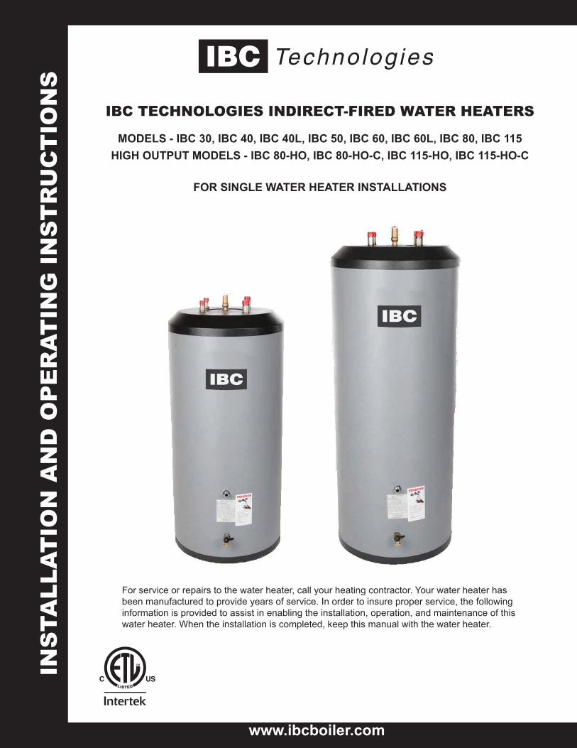
IBC TECHNOLOGIES INDIRECT-FIRED WATER HEATERS
MODELS - IBC 30, IBC 40, IBC 40L, IBC 50, IBC 60, IBC 60L, IBC 80, IBC 115HIGH OUTPUT MODELS - IBC 80-HO, IBC 80-HO-C, IBC 115-HO, IBC 115-HO-C
FOR SINGLE WATER HEATER INSTALLATIONS
For service or repairs to the water heater, call your heating contractor. Your water heater has been manufactured to provide years of service. In order to insure proper service, the following information is provided to assist in enabling the installation, operation, and maintenance of this water heater. When the installation is completed, keep this manual with the water heater.
INSTALLATION AND OPERATION INSTRUCTIONS2
IBC INDIRECT WATER HEATERS - ALL MODELS
HAZARDS &PRECAUTIONS
WARNINGPoints out a potentially hazardous situation which must be avoided to prevent serious injury or death.
CAUTIONPoints out a potentially hazardous situation which must be avoided to prevent possible moderate injury and/or property damage
NOTEPoints out installation, maintenance and operation details that will result in enhanced efficiency, longevity and proper operation of your boiler.
DANGERPoints out an immediately hazardous situation which must be avoided in order to prevent serious injury or death.
1) - General Information
IMPORTANT INFORMATION – READ CAREFULLY
NOTE
This equipment shall be installed in accordance with those installation regulations required in the area where the installation is to be made. These regulations shall be carefully followed in all cases. Authorities having jurisdiction shall be consulted before the installations are made.
All wiring on water heaters shall be in accordance with the National Electrical Code and/or local regulations.
WARNING
Failure to read and comply with all instructions and applicable National and local codes may result in hazardous conditions that could result in property damage and injury to occupants which in extreme cases might result in death.When using electrical appliances, basic safety precautions to reduce the risk of fire, electric shock, or injury to persons should be followed, including:READ ALL INSTRUCTIONS BEFORE USING THIS WATER HEATER.
1. Water heaters equipped with electric backup must be grounded. Con-nect only to properly grounded outlet. See “GROUNDING INSTRUC-TIONS” found in Section IV.
2. Install or locate this water heater only in accordance with the provided installation instructions
3. Use this water heater only for its intended use as described in this manual.
4. Do not use an extension cord with electric back-up water heaters. If no receptacle is available adjacent to the water heater, contact a qualified electrician to have one properly installed.
5. As with any appliance, close supervision is necessary when used by children.
6. Do not operate this water heater if it is not working properly, or if it has been damaged or dropped.
7. Installation, start-up and servicing of IBC Indirect Water Heaters must be done with due care and attention, and should only be performed by competent, qualified, licensed and trained plumbing and heating technicians. Contact nearest authorized service facility for examination, repair, or adjustment.
SAVE THESE INSTRUCTIONS
IMPORTANT SAFETY INSTRUCTIONS
3INSTALLATION AND OPERATION INSTRUCTIONS
IBC INDIRECT WATER HEATERS - ALL MODELS
Table of Contents:1. General Information and
Specifications
2. Pre-Installation
3. Piping
4. Electrical
5. Operation
6. Maintenance
7. Troubleshooting
8. Schematics
9. Water Heater Selection Data
WARNING
Improper installation, adjustment, alteration, service or maintenance can cause property damage, personal injury, or loss of life. Read and understand the entire manual before attempting installation, start-up, operation, or service. Installation and service must be performed only by an experienced, skilled installer or service agency.
This water heater contains very hot water under high pressure. Do not unscrew any pipe fittings or attempt to disconnect any components of this water heater without positively assuring that the water is cool and has no pressure. Always wear protective clothing and equipment when installing, starting up or servicing this water heater to prevent scalding injuries. Do not rely on the pressure and temperature gauges to determine the temperature and pressure of the water heater. This water heater contains components that become very hot when the boiler is operating. Do not touch any components unless they are cool.
Failure to follow all instructions in the proper order can cause personal injury or death. Read all instructions, including all those contained in component manufacturers’ manuals before installing, starting up, operating, maintaining, or servicing the water heater.
CAUTION
To reduce the risk of excessive pressures and temperatures in this water heater, install temperature and pressure protective equipment required by local codes but no less than a combination temperature relief valve certified by a nationally recognized testing laboratory that maintains periodic inspection of production of listed equipment or materials, as meeting the requirements for Relief Valves and Automatic Shutoff Devices for Hot Water Supply Systems, ANSI Z21.22-latest edition. This valve must be marked with a maximum set pressure not to exceed the marked working pressure of the water heater. Install the valve into an opening provide and marked for this purpose in the water heater, and orient it or provide tubing so that any discharge from the valve will exit only within 6 inches above, or at any distance below, the structural floor, and cannot contact any live electrical part. The discharge opening must not be blocked or reduced in size under any circumstances.
The heat transfer medium must be water or other non-toxic fluid having a toxicity rating or class of 1, as listed in clinical Toxicology of Commercial Products, latest edition.
The pressure of the heat transfer medium must be limited to the maximum of 30 or 75 psig (depending on IBC boiler model) by its approved pressure relief valve.
DANGER
DO NOT store or use gasoline or other flammable vapors or liquids in the vicinity of this or any other appliance.
If you smell gas vapors, DO NOT try to operate any appliance - DO NOT touch any electrical switch or use any phone in the building. Immediately, call the gas supplier from a remote located phone. Follow the gas supplier’s instructions or if the supplier is unavailable, contact the fire department.
CAUTIONInstallation, start-up and servicing of IBC boilers and Water Heaters must be done with due care and attention, and should only be performed by competent, qualified, licensed and trained heating technicians.
NOTEThe instructions in this manual focus almost entirely on installations where the IBC water heater is used in conjunction with a compatible IBC Boiler. It is necessary for the Installer and Designer to read the IBC Boiler manuals and application notes, to ensure that finished installations will operate in harmony and deliver optimal energy savings and efficiency.
IBC water heaters are compatible with most other boiler makes, and can be an excellent choice, but Installers and Designers must tailor their designs to the specific control, operational and installation requirements of any alternate Boiler.
INSTALLATION AND OPERATION INSTRUCTIONS4
IBC INDIRECT WATER HEATERS - ALL MODELS
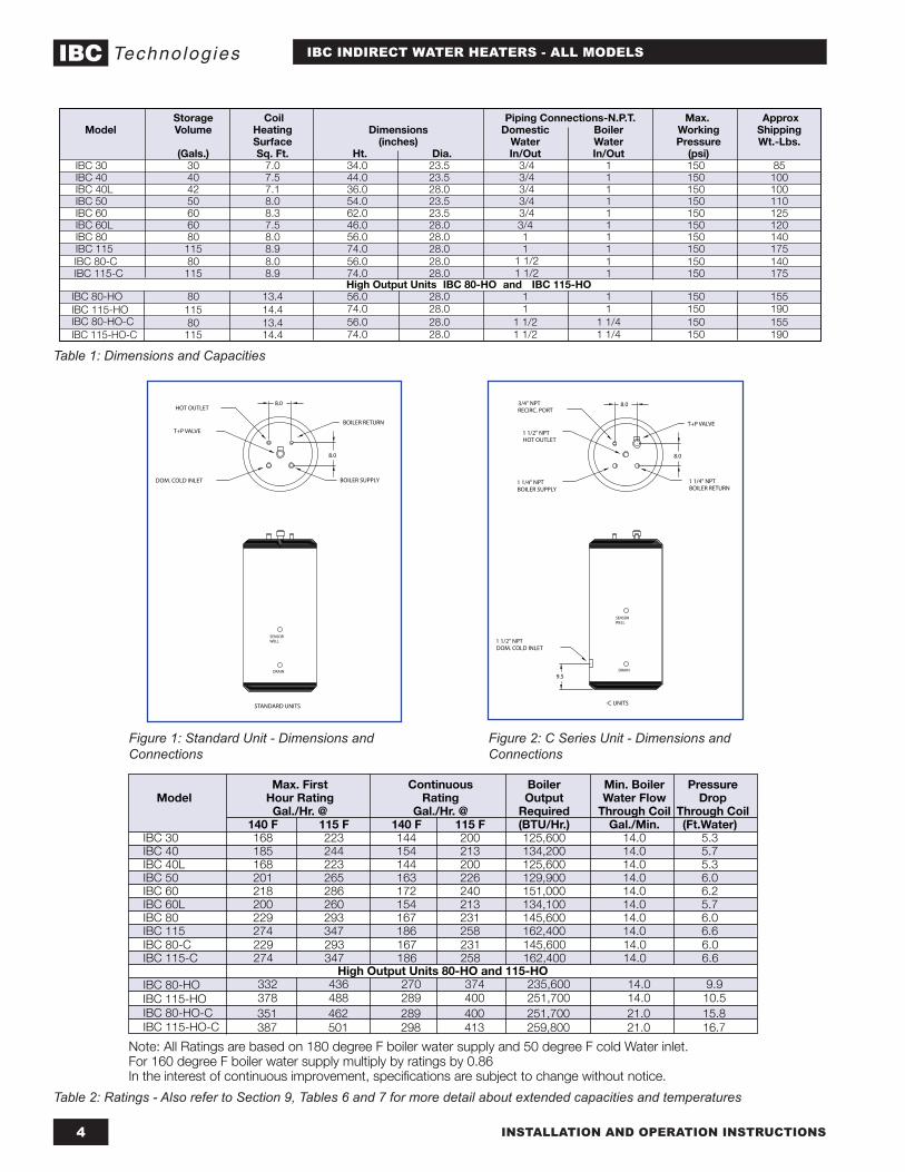
Max. First Continuous Boiler Min. Boiler Pressure Model Hour Rating Rating Output Water Flow Drop Gal./Hr. @ Gal./Hr. @ Required Through Coil Through Coil 140 F 115 F 140 F 115 F (BTU/Hr.) Gal./Min. (Ft.Water)
IBC 30 168 223 144 200 125,600 14.0 5.3IBC 40 185 244 154 213 134,200 14.0 5.7IBC 40L 168 223 144 200 125,600 14.0 5.3IBC 50 201 265 163 226 129,900 14.0 6.0IBC 60 218 286 172 240 151,000 14.0 6.2IBC 60L 200 260 154 213 134,100 14.0 5.7IBC 80 229 293 167 231 145,600 14.0 6.0IBC 115 274 347 186 258 162,400 14.0 6.6
High
Output
Units
80-HO
and
115-HO 332 436 270 374 235,600 14.0 9.9378 488 289 400 251,700 14.0 10.5351 462 289 400 251,700 21.0 15.8387 501 298 413 259,800 21.0 16.7
Note: All Ratings are based on 180 degree F boiler water supply and 50 degree F cold Water inlet.For 160 degree F boiler water supply multiply by ratings by 0.86In the interest of continuous improvement, specifications are subject to change without notice.
IBC 80-C IBC 115-C
IBC 80-HOIBC 115-HOIBC 80-HO-CIBC 115-HO-C
229 293 167 231 145,600 14.0 6.0274 347 186 258 162,400 14.0 6.6
T+P VALVE
1 1/4" NPT BOILER SUPPLY
1 1/4" NPTBOILER RETURN
1 1/2" NPTDOM. COLD INLET
SENSORWELL
DRAIN
-C UNITS
8.0
8.0
9.5
3/4" NPTRECIRC. PORT
1 1/2" NPTHOT OUTLET
T+P VALVE
BOILER SUPPLY
BOILER RETURN
SENSORWELL
DRAIN
STANDARD UNITS
8.0
8.0
HOT OUTLET
DOM. COLD INLET
Table 1: Dimensions and Capacities
Figure 1: Standard Unit - Dimensions and Connections
Table 2: Ratings - Also refer to Section 9, Tables 6 and 7 for more detail about extended capacities and temperatures
Figure 2: C Series Unit - Dimensions and Connections
Storage Coil Piping Connections-N.P.T. Max. Approx Model Volume Heating Dimensions Domestic Boiler Working Shipping Surface (inches) Water Water Pressure Wt.-Lbs. (Gals.) Sq. Ft. Ht. Dia. In/Out In/Out (psi)
IBC 30 30 7.0 34.0 23.5 3/4 1 150 85IBC 40 40 7.5 44.0 23.5 3/4 1 150 100IBC 40L 42 7.1 36.0 28.0 3/4 1 150 100IBC 50 50 8.0 54.0 23.5 3/4 1 150 110IBC 60 60 8.3 62.0 23.5 3/4 1 150 125IBC 60L 60 7.5 46.0 28.0 3/4 1 150 120IBC 80 80 8.0 56.0 28.0 1 1 150 140IBC 115 115 8.9 74.0 28.0 1 1 150 175
High
Output
Units
IBC 80-HO
and
IBC 115-HOIBC 80-HO 80 13.4 56.0 28.0 1 1 150 155IBC 115-HO 115 14.4 74.0 28.0 1 1 150 190IBC 80-HO-C 80 13.4 56.0 28.0 1
1/2 1
1/4 150 155IBC 115-HO-C 115 14.4 74.0 28.0 1
1/2 1
1/4 150 190
IBC 80-C 80 8.0 56.0 28.0 1 150 140IBC 115-C 115 8.9 74.0 28.0 1 150 175
1 1/2 1 1/2
5INSTALLATION AND OPERATION INSTRUCTIONS
IBC INDIRECT WATER HEATERS - ALL MODELS
2) - Pre-Installation Considerations
Inspect shipment carefully for signs of damage. All equipment is carefully inspected and packed. IBC’s responsibility ceases upon delivery of the water heater to the carrier in good condition. Any claims for damage or shortage, must be filed immediately against the carrier by the consignee. No claims for variances or shortages will be allowed by the Manufacturer, unless they are presented within sixty days after receipt of the equipment.Installation must conform to the requirements of the authority having jurisdiction. In the absence of such requirements, it must conform to the National Plumbing Code and the National Electrical Code ANSI/NFPA No. 70, current edition.
IMPORTANT CONSIDERATIONS BEFORE INSTALLATION
1. Water heater sizingChoose the water heater model based on the expected water usage for the given site. The average residence with one shower or more will require a Model 40 or larger. The Model 30 should only be considered for residences with minimal water demand, or for commercial applications without showers.Factors that increase water demand dramatically include high flow shower heads, hot tubs, and the use of more than one shower at a time. Increase the tank size if these factors are present. Carefully review the IBC Water Heater specifications contained herein, and consult ASHRAE sizing guides and other reliable references.Dimensions, weights, ratings, and capacities are outlined in Tables 1 and 2.
2. Boiler sizingThe water heater will provide the rated performance only if it is used with a boiler with a heating capacity of at least as much as the capacity ratings in Table 2. If the boiler has less capacity, the water heating output will be reduced. To determine performance with other boiler outputs, refer to the expanded capacity tables #6 and #7 in Section 9 of this manual.
3. Circulator sizingRefer to Table 2 and table 5 for the flow through the water heater coil and the pressure drop at minimum flow. Calculate the pressure drop across all piping and fittings connected to the water heater zone. Be sure to include all zone valves, check valves, and shut-off valves. It is recommended that the water heater zone be piped with 1” pipe around the entire loop on typical residential sites.
A. System Zone ControlThe water heater must be installed as a separate zone from the space heating system. The water heating zone’s piping and circulator must be sized for the minimum flow rate with all the zones in use and a maximum flow with only the water heater in use. This is the reason that the best method of zone control is with circulators.The three most common systems are:1. Zone Circulators - The space heating zones use a circulator for each zone,
and the water heater is controlled with an additional circulator. See Section 8, Mechanical Drawings #1, #2 and #3.
2. Hybrid System- The space heating zones use zone valves for each zone, and the water heater is controlled with an additional circulator. See Section 8, Mechanical Drawing #5.
Supplied with this Water Heater:
The IBC Water Heater is shipped with the following items:
1 x 210°F x 150 psig T & P relief valve
1 x IBC 10KΩ Temperature sensor
Installation Instructions
Warranty Sheet
NOTEIf this water heater is to be installed with a different make of boiler than IBC, the sensor supplied will not be compatible. The temperature well in the IBC water heater is designed to accept a number of different aquastat thermostats which can be ordered separately. Contact your IBC Distributor to order an alternate temperature controller.
NOTEThere are a number of jurisdictional issues that may prevent this water heater from being accepted by local Inspection Authorities. Issues such as double-wall heat exchanger requirements, local or State registration requirements, may cause an installation to be rejected.
It is essential that the Installer check with local Officials to ensure acceptance of this equipment prior to the installation.
IBC will not accept liability for any of these situations, although we will assist in any way we can, in order to help gain acceptance.
INSTALLATION AND OPERATION INSTRUCTIONS6
IBC INDIRECT WATER HEATERS - ALL MODELS
3. Zone Valves – The space heating zones use zone valves for each zone, and the water heater is controlled with an additional zone valve. Select a valve with a low pressure drop, and adequate pipe size to assure minimum flow. See Section 8, Mechanical Drawing #4.
B. Priority or Non-Priority for Hot WaterOption 1 – Priority. The demand for space heating is interrupted until the hot water demand is satisfied. This option provides the maximum delivery of hot wa-ter. IBC boilers are easily configured to operate the Hot Water as a priority load.Priority is recommended when: 1. The boiler output is less than 100,000 Btu per hour, or2. The boiler output required to satisfy the hot water demand is more than 50%
of the boiler output needed to satisfy the space heating demand, or3. When an interruption in space heating can be tolerated during long domestic
hot water draws.The preferred strategy when using an IBC boiler is to use a load circulator for domestic hot water and the IBC controller to switch the circulator on and off using the IBC control logic and sequential priority hardware. In most cases the delay in space heating will not be noticed because of the rapid recovery of the water heater. Certain water heater malfunctions, such as a failed sensor or circulator, might delay space heating temporarily until the IBC controller internal logic takes over and operates all loads equally until the malfunction is corrected.Option 2 – Non-Priority. The boiler output is divided between space heating and water heating. Heating of domestic hot water can be reduced during simul-taneous space and water heating demands. The maximum amount of reduction depends on the boiler output, the number of space heating zones calling, the space heating target water temperature, and the amount of boiler water flow split between the space heating and zones and the water heater zone. Most IBC boil-ers are now shipped with “Load Pairing” software that can provide DHW priority with simultaneous space heating allowed during moderate heating demands.C. Locating the water heater.The water heater should be located in an area where water leakage from the tank or connections will not result in damage to areas adjacent to the water heater or to lower floors of the structure. When such a location can not be avoided, a suit-able drain pan must be installed under the water heater, and the drain pan must be connected to a drain.The water heater should be installed as close to the boiler as is practical for easy access for service. The unit is designed for installation on combustible flooring and in alcoves, closets, etc.
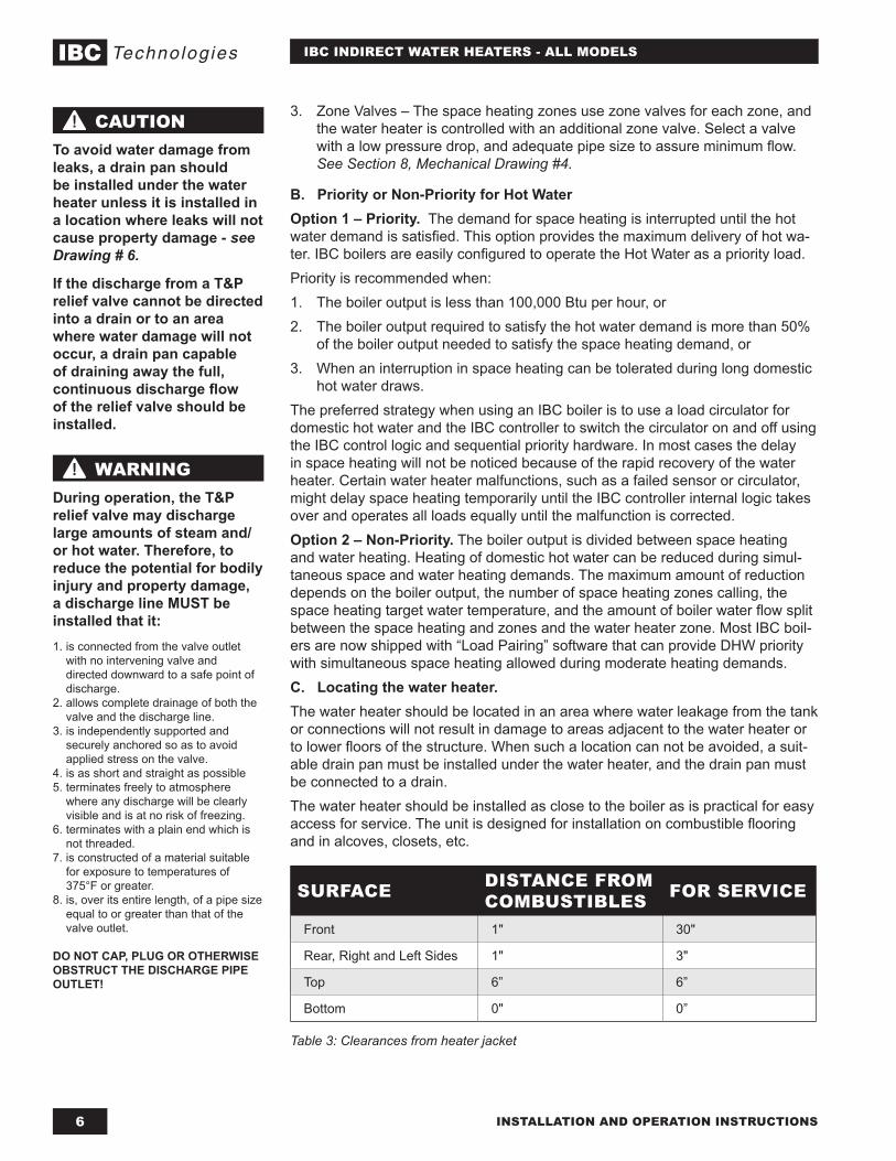
SURFACE DISTANCE FROM COMBUSTIBLES FOR SERVICE
Front 1" 30"
Rear, Right and Left Sides 1" 3"
Top 6” 6”
Bottom 0" 0”
Table 3: Clearances from heater jacket
WARNINGDuring operation, the T&P relief valve may discharge large amounts of steam and/or hot water. Therefore, to reduce the potential for bodily injury and property damage, a discharge line MUST be installed that it:1. is connected from the valve outlet
with no intervening valve and directed downward to a safe point of discharge.
2. allows complete drainage of both the valve and the discharge line.
3. is independently supported and securely anchored so as to avoid applied stress on the valve.
4. is as short and straight as possible5. terminates freely to atmosphere
where any discharge will be clearly visible and is at no risk of freezing.
6. terminates with a plain end which is not threaded.
7. is constructed of a material suitable for exposure to temperatures of 375°F or greater.
8. is, over its entire length, of a pipe size equal to or greater than that of the valve outlet.
DO NOT CAP, PLUG OR OTHERWISE OBSTRUCT THE DISCHARGE PIPE OUTLET!
CAUTIONTo avoid water damage from leaks, a drain pan should be installed under the water heater unless it is installed in a location where leaks will not cause property damage - see Drawing # 6.
If the discharge from a T&P relief valve cannot be directed into a drain or to an area where water damage will not occur, a drain pan capable of draining away the full, continuous discharge flow of the relief valve should be installed.
7INSTALLATION AND OPERATION INSTRUCTIONS
IBC INDIRECT WATER HEATERS - ALL MODELS
D. Additional recommended components1. Shut-off valves. Allows the isolation of the water heater from the boiler
system during service.2. Unions. Allows for easy locating or removal.3. Vacuum breaker. Protects the water heater from collapse if a hot tank is
valved off to service other components in the system.4. Thermal expansion tank. If the water heater is installed in a closed water
supply system, such as a system having a back flow preventer in the cold water supply line, the installation of a thermal expansion tank is required.
5. Refer to drawing #6 in this manual for suggested external components.
E. Removing the Existing Domestic Water Heating System
If the IBC water heater is being installed in an older hydronic system that does not use an IBC boiler:• External Tankless Heater - Disconnect all lines to the boiler and plug the
boiler fittings. Disconnect the external heater from the boiler piping, and the domestic piping systems.
• Internal Tankless Heaters - Disconnect the domestic piping. Do not plug the cold water or the hot water fittings in the internal tankless coil. Leave the coil in the boiler with the cold and hot water fittings open to prevent pressure build-up in the coil.
If the IBC water heater is being installed to replace an electric or direct fired gas or oil water heater: Disconnect the water piping and either strip back to the nearest main line and cap off, or re-use for the new tank, whichever is appropriate.• Electric Water Heater - Disconnect the electrical supply wiring and remove
back to the breaker panel or terminate in an approved junction box. Work must conform to all applicable electrical codes.
• Direct Fired Gas Water Heater - Disconnect the gas supply line to the heater, strip back to the nearest mains piping and cap off. Remove vent connector back to the common venting system and seal off or abandon as applicable. Work must conform to all applicable codes.
• Direct Fired Oil Water Heater - Disconnect the oil supply line to the heater, strip back to the tank or nearest mains piping and cap off. If oil heating system is to be abandoned completely, ensure proper removal and disposal of old oil tank and remaining fuel oil. Remove vent connector back to the common venting system and seal off or abandon as applicable. Work must conform to all applicable codes.
F. Water QualityImproper water quality will reduce the expected life of the water heater. Hard water, sediment, high or low Ph, and high levels of chlorides in the domestic water should be avoided. Sediment and hard water will eventually coat the heating coil inside the water heater and reduce the rate of hot water production and may, eventually cause a failure. High or low Ph and/or high chloride concentrations will cause corrosion and eventually failure. A filter is strongly recommended where sediment is present in the water. A water softening system is recommended for areas with hard water.In an area where the water quality is not known, a water quality test should be performed.
CAUTIONDo not operate the IBC water heaters in areas where the Ph is above 8.0 or below 6.0, and/or with chloride concentrations greater than 80 parts per million (ppm). IBC’s standard warranty does not cover problems caused by improper water Ph or excessive levels of chlorides.
WARNINGThere are a number of conditions, including improper control settings, which could result in elevated tank temperatures from ANY type of water heater. An overheating hazard can result, potentially causing serious personal injury and/or property damage.
IBC Highly recommends as a minimum precaution, the installation of a point of source ASSE 1017 approved thermostatic mixing valve on the outlet of the water heater. Local jurisdictions may require more comprehensive protective measures depending on the place of installation (ie. schools, nursing homes, etc.). Check with local Authorities for direction.
CAUTIONWhen removing any fuel burning appliance from a common venting system, the opening must be properly sealed off and; if there are remaining appliances still using the common venting system, the vent must be examined to ensure that it is not over-sized as a result of having removed the old water heater.
INSTALLATION AND OPERATION INSTRUCTIONS8
IBC INDIRECT WATER HEATERS - ALL MODELS
3) - Piping
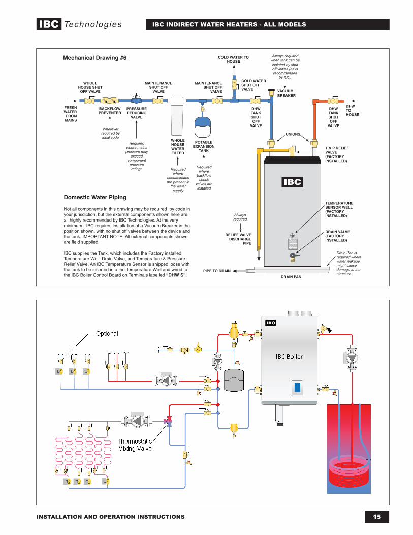
A. Domestic water piping - See Section 8, Mechanical Drawing # 6
1. Drain the domestic water system.• Shut off the cold water supply at the main shutoff valve.• Open one or more faucets to relieve the pressure. Open the system drain,
leaving the faucets open.2. Position the water heater in the final location.3. Connect the cold water supply piping. • Install piping onto cold inlet connection - • Connect to cold water supply connection using the following suggested
components where applicable: A union, a heat trap, a shut-off valve, an expansion tank, a back flow preventer, a vacuum breaker and a filter (recommended to prevent sediment buildup).
4. Connect the domestic hot water piping.• Install piping on to hot water supply connection using a union, a heat trap,
and a shut-off valve. • Pipe the relief valve discharge so that the discharge from the valve will exit
only within 6 inches above, or at any distance below, the structural floor, and cannot contact any live electrical part. The discharge opening must not be blocked or reduced in size under any circumstances.
5. Fill the water heater tank.• Open all faucets to allow air to purge from the tank and piping. Remove
screens on faucets.• Open the domestic hot water shut-off valve.• Slowly open the cold water inlet shut-off valve.• Purge all of the air from the domestic water system. Allow water to run so the
tank is completely purged of any debris. Run the water long enough so that it runs clear and to change at least one tank volume change past full. Close all faucets. Reinstall all of the screens in the faucets.
• Check the system for leaks. Repair as required.
B. Boiler water piping. See Figures in Section 8.1. Determine where the boiler, the space heating, and the water heater
connections should be made based on the type of piping system that is either in place, or is to be installed for a new hydronic system installation. See Schematic drawings in Section 8 for direction.
2. It is recommended that minimum size 1” pipe be used on the water heater zone to ensure adequate flow, larger sizes (80 and 115 models) min 1 1/4”.
Zone Circulator System
For space heating systems that use Zone Circulators only; refer to Mechanical Drawings #1, #2 and #3 in Section 8 of this manual. The water heater connection labeled “BOILER SUPPLY” should be piped to the boiler supply piping after the air purger and before the space heating takeoffs - for primary/secondary systems, see Mechanical Drawing #1 - parallel piping, see Mechanical drawings #2 and #3. Mount the water heater circulator as close as is practicable to the water heater, and make sure the flow arrow points toward the water heater. The use of shut-off valves is recommended for future service convenience.
NOTEInstallers should inquire of local water purveyors as to the suitability of their supply for use in hydronic heating systems.
If water quality is questionable, a local water treatment expert must be consulted for testing, assessment and, if required, treatment.
Alternatively, water or hydronic fluid of known quality can be brought to the site.
WARNINGDo not use automotive-type ethylene or other types of automotive glycol antifreeze, or undiluted antifreeze of any kind on the boiler water side of the system. This may result in severe boiler or tank damage. It is the responsibility of the Installer to ensure that glycol solutions are formulated to inhibit corrosion in hydronic heating systems of mixed materials. Improper mixtures and chemical additives may cause damage to ferrous and non-ferrous components as well as non-metallic, wetted components, normally found in hydronic systems.
Ethylene glycol is toxic, and may be prohibited for use by codes applicable to your installation location. For environmental and toxicity reasons, IBC recommends only using non-toxic propylene glycol, and non-toxic boiler water additives of any kind.
9INSTALLATION AND OPERATION INSTRUCTIONS
IBC INDIRECT WATER HEATERS - ALL MODELS
The water heater connection labeled “BOILER RETURN” should be piped to the boiler return piping as close to the boiler as possible and after any flow control or check valves in the space heating return piping. The use of a union and a shut-off valve is recommended. The use of a check valve is required to prevent back flow through the water heater during operation of the space heating system.
Zone Valve System
It is recommended that minimum size 1” pipe and 1” full-port zone valves with a high CV be used on the water heater zone to ensure adequate flow. For a space heating system that uses Zone Valves only, see Section 8, Mechanical Drawing #4. Some important details for Hybrid Systems - see Section 8, Mechanical Drawing #5. The water heater connection labeled “BOILER SUPPLY” should be piped to the boiler supply piping after the air purger and before the space heating circulator. Installing the check valve, as illustrated in the drawing is necessary to prevent reverse flow from the heating system back through the water heater. Mount the water heater circulator as close as possible to the water heater, and make sure the flow arrow points toward the water heater. The use of a shut-off valve is recommended for future service convenience.The water heater connection labeled “BOILER RETURN” should be piped to the boiler return piping as close to the boiler as possible and after any flow control or check valves in the space heating return piping. The use of a union and a shut-off valve is recommended. The use of a check valve is required to prevent back flow through the water heater during operation of the space heating system.
4) - Electrical
1. Install electric wiring and grounding in accordance with the National Electrical code and local regulations.
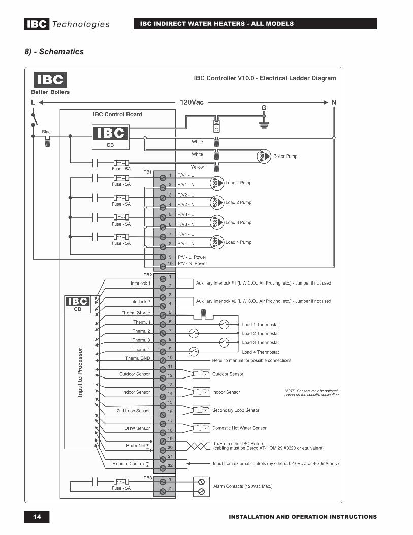
2. All water heaters are supplied with a temperature sensor that connects to the IBC control board “DWH S” terminals with standard 2-wire, 18 gauge thermostat wire. For other boiler makes, an aquastat thermostat is required.
3. Refer to Mechanical Drawings #1, #2 and #3 for separate circulator wiring.4. Refer to schematics #4, #5 for zone valve wiring.5. Reference should be made to the Installation Manual for the boiler as well.
Temperature Sensor
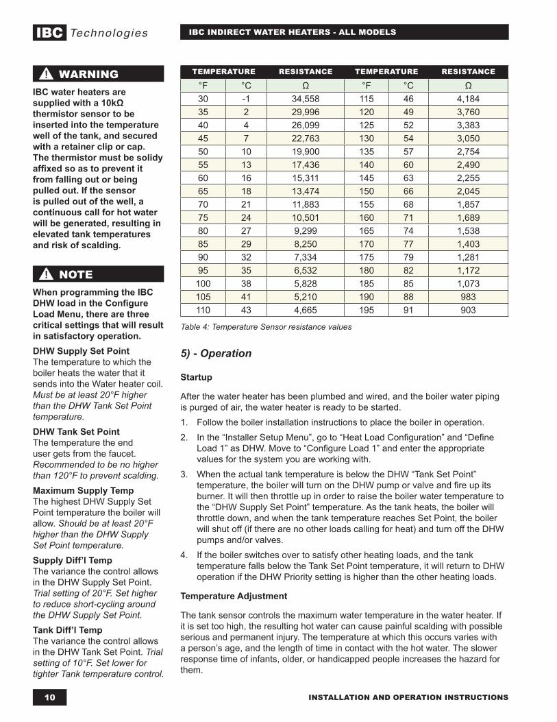
The Temperature Sensor supplied with the IBC Water Heater is an NTC Thermistor type with a resistance of 10,000 ohms at 25°C and β = 3892. IBC does not recommend using 3rd party supplied sensors. Compatible water temperature sensors are readily available from your IBC distributor.The resistance of the temperature sensor varies inversely with temperature. To test, measure the temperature of the sensed environment and compare with the value derived from the measurement of the resistance (obtained by connecting a good quality test meter capable of measuring up to 5,000 kΩ (5,000,000Ω) at the controller end of the sensor lead).To obtain a resistance reading, remove power to the boiler. The sensor leads must be disconnected from the terminal strip while taking the reading. Do not grip the sensor leads in your hands or place them on or against a conductive surface or the reading will be compromised. Place multi-meter probes onto the bare wire ends of the leads and obtain the reading. Compare the reading to the actual sensor temperature and the resistance value listed for that temperature in Table 4 (below). Do not apply voltage to the sensor (damage may result).
NOTEThe piping drawings in Section 8 of this manual are simple schematic guides to a successful installation. There are many necessary components not shown, and details such as thermal traps are left out so the drawings have greater clarity. We require that our boilers and tanks be installed by licensed and experienced trades people who are familiar with the applicable local and national codes. System design is to be completed by an experienced hydronic designer or Engineer.
The application drawing(s) shown in this manual are only part of the finished design.
It is absolutely neccessary to carefully read and follow these installation instructions, and just as importantly, the installation instructions or the boiler model you are using with this water heater.
DANGERDO NOT connect thermistor sensors to “Therm” terminals on the IBC control board. An overheating hazard can result, potentially causing serious personal injury and/or property damage.
WARNINGThe Thermistor temperature sensor supplied with the IBC water heater is unlikely to be compatible with other makes of boiler or controls, and its use may create a hazardous condition. DO NOT USE THE IBC SENSOR WITH OTHER APPLIANCE MAKES.
INSTALLATION AND OPERATION INSTRUCTIONS10
IBC INDIRECT WATER HEATERS - ALL MODELS
TEMPERATURE RESISTANCE TEMPERATURE RESISTANCE
°F °C Ω °F °C Ω30 -1 34,558 115 46 4,18435 2 29,996 120 49 3,76040 4 26,099 125 52 3,38345 7 22,763 130 54 3,05050 10 19,900 135 57 2,75455 13 17,436 140 60 2,49060 16 15,311 145 63 2,25565 18 13,474 150 66 2,04570 21 11,883 155 68 1,85775 24 10,501 160 71 1,68980 27 9,299 165 74 1,53885 29 8,250 170 77 1,40390 32 7,334 175 79 1,28195 35 6,532 180 82 1,172
100 38 5,828 185 85 1,073105 41 5,210 190 88 983110 43 4,665 195 91 903
Table 4: Temperature Sensor resistance values
5) - Operation
Startup
After the water heater has been plumbed and wired, and the boiler water piping is purged of air, the water heater is ready to be started. 1. Follow the boiler installation instructions to place the boiler in operation.2. In the “Installer Setup Menu”, go to “Heat Load Configuration” and “Define
Load 1” as DHW. Move to “Configure Load 1” and enter the appropriate values for the system you are working with.
3. When the actual tank temperature is below the DHW “Tank Set Point” temperature, the boiler will turn on the DHW pump or valve and fire up its burner. It will then throttle up in order to raise the boiler water temperature to the “DHW Supply Set Point” temperature. As the tank heats, the boiler will throttle down, and when the tank temperature reaches Set Point, the boiler will shut off (if there are no other loads calling for heat) and turn off the DHW pumps and/or valves.
4. If the boiler switches over to satisfy other heating loads, and the tank temperature falls below the Tank Set Point temperature, it will return to DHW operation if the DHW Priority setting is higher than the other heating loads.
Temperature Adjustment
The tank sensor controls the maximum water temperature in the water heater. If it is set too high, the resulting hot water can cause painful scalding with possible serious and permanent injury. The temperature at which this occurs varies with a person’s age, and the length of time in contact with the hot water. The slower response time of infants, older, or handicapped people increases the hazard for them.
WARNINGIBC water heaters are supplied with a 10kΩ thermistor sensor to be inserted into the temperature well of the tank, and secured with a retainer clip or cap. The thermistor must be solidy affixed so as to prevent it from falling out or being pulled out. If the sensor is pulled out of the well, a continuous call for hot water will be generated, resulting in elevated tank temperatures and risk of scalding.
NOTEWhen programming the IBC DHW load in the Configure Load Menu, there are three critical settings that will result in satisfactory operation.DHW Supply Set PointThe temperature to which the boiler heats the water that it sends into the Water heater coil. Must be at least 20°F higher than the DHW Tank Set Point temperature.DHW Tank Set PointThe temperature the end user gets from the faucet. Recommended to be no higher than 120°F to prevent scalding.Maximum Supply TempThe highest DHW Supply Set Point temperature the boiler will allow. Should be at least 20°F higher than the DHW Supply Set Point temperature.Supply Diff’l TempThe variance the control allows in the DHW Supply Set Point. Trial setting of 20°F. Set higher to reduce short-cycling around the DHW Supply Set Point.Tank Diff’l TempThe variance the control allows in the DHW Tank Set Point. Trial setting of 10°F. Set lower for tighter Tank temperature control.
11INSTALLATION AND OPERATION INSTRUCTIONS
IBC INDIRECT WATER HEATERS - ALL MODELS
It is recommended that the thermostat be set for the lowest possible temperature that satisfies your needs. This will also provide you with the lowest energy consumption and cost.Check the water temperature at a hot water faucet soon after the tank thermostat has satisfied, and the circulator and the boiler have turned off. Adjust as needed.Lowering the thermostat setting will not have an immediate effect on the water temperature because the stored water will have to be used and the thermostat must go through the cycle of heating cold water and satisfying at the new, lower temperature. Additional temperature checks should follow the completion of a heating cycle. Further adjustments may be required after you have used the water heater.
6) - Maintenance
The water heater is intended to provide many years of reliable service. Components, such as sensors and relief valves, may be subject to failures that require service. Depending on the quality of the water supply, sediment and/or scale may coat the heating coil in the tank and reduce hot water recovery rate. Failure to use the correct procedures or parts can result in unsafe operation.The owner should arrange to have the following inspections and simple maintenance procedures done at the suggested frequencies.
1. Boiler and Domestic Water Piping (Annual)Check all piping for signs of leakage at the joints, unions and shut-off valves. Repair as required.
2. Temperature and Pressure Relief Valve (Annual)
3. Sediment (Annual except where harsh water quality may require more frequent service)Depending on water conditions, a varying amount of sediment may collect in the tank. Levels requiring service are indicated by a small temperature difference between the boiler supply and return lines, and a reduced recovery rate. Repeated flushing usually clears such material. As a preventive measure, water should be drawn from the drain valve until it runs clear and the installation of a water filter should be considered.
4. Scale (Annual)Hard water may cause scale buildup on the outside of the heating coil inside the tank. A water softener will help prevent this problem. Symptoms are identical to sediment buildup. If repeated flushing does not resolve the problem, chemical cleaning may be required. Proceed as follows:
Chemical cleaning of the heating coil:
1. To avoid water damage, shut off the cold water supply to the water heater.2. Make a note of the DHW temperature control setting on the IBC control,
and turn off the power to the boiler and water heater.3. Relieve the water pressure in the tank by opening a hot water faucet. This
will reduce the risk of scalding.4. Remove the relief valve from the water heater.5. Drain the water heater until the water is at a level equal to 3” above the
thermostat well. This level will cover the coil and the thermostat.
CAUTIONAs a precaution:
After the water heater has reached its setpoint temperature, the installer should locate a faucet that is unprotected by an over-temperature device.
Turn the faucet on full, and allow it to run long enought to ensure the water and piping have been heated up to the discharge temperature of the tank.
Using an accurate thermometer, test the water temperature to ensure it is withing plus or minus 10°F of the setpoint. If there is more deviation, the cause should be determined and corrective measures taken.
INSTALLATION AND OPERATION INSTRUCTIONS12
IBC INDIRECT WATER HEATERS - ALL MODELS
7) - Troubleshooting
6. Using a funnel, pour one gallon of commercial ice maker cleaning solution into the tank through the relief valve opening. Follow the instructions, cautions, and warnings supplied with the cleaning solution.
7. Turn on the power to the boiler and water heater, program the IBC control to its highest DHW temp. setting, and allow the boiler to heat the water until the control is satisfied. If the boiler control is not satisfied after 45 minutes of operation, program the IBC DHW control setting to its lowest temp.
8. Allow the heated solution to set in the tank 30 minutes.9. Drain the tank completely using fittings and hoses, as required, to reach a
drain.10. Fill the water heater tank with fresh, cold, water and drain it completely.
Repeat filling and draining at least three (3) times to flush all of the cleaning solution from the tank.
11. Reinstall the relief valve and the drain piping.12. Open the cold water supply and fill the tank with water. Purge the air from
the tank and the piping by opening the cold and hot water faucets in the house.
13. Return the IBC DHW control setting to the temperature noted in Step 2.
SYMPTOM DIAGNOSIS REMEDY
WATER AT FAUCETS TOO HOT
IBC boiler DHW temperature setting too high
• Reduce the DHW Tank Set Point temperature in the Configure Load Menu
DHW temperature sensor problems giving false reading to IBC Control
• Sensor has fallen from well• Sensor giving incorrect resistance reading• sensor connected to Therm terminals
instead of DHW S terminals• improper 3rd party sensor installed in well
•
WATER AT FAUCETS TOO COOL
IBC boiler DHW temperature setting too low
• Increase the DHW Tank Set Point temperature in the Configure Load Menu
IBC boiler DHW Maximum Supply Temp. setting too low
• Make sure the Maximum Supply Temp. setting is at least 10°F higher than the DHW Supply Setpoint PLUS 1/2 of the Supply Diff’l Temp setting.
13INSTALLATION AND OPERATION INSTRUCTIONS
IBC INDIRECT WATER HEATERS - ALL MODELS
SYMPTOM DIAGNOSIS REMEDY
NO HOT WATER ATFAUCETS
Boiler does not operate
• Ensure boiler power is on• Ensure the boiler is programed for DHW and
the water temperatures are set properly• Check the tank temperature on the IBC
screen, Open or Short + sensor or wiring issue
Water Heater Circulator does not operate
• Follow steps for Boiler does not operate• Ensure the boiler green terminal strip has
power (120V) to the lower 2 terminals P/VL and P/VN
• Check wiring connections at the circulator• Measure voltage at the circulator during a
call for heat, should see 120VAC +/- 12VAC• If power is at the circulator and connections
are correct, replace circulator
Water heater zone valve does not open
• Follow steps for Boiler does not operate
• Check for 24VAC at the zone valve while there is a call for heat, if correct voltage is available and connections are good, replace the zone valve.
• If the zone valve is connected to the P/V terminals on the IBC boiler, ensure 24VAC has been applied to the P/VL and P/VN terminals on the bottom of the green terminal strip and in the Installer Menu the Load Control has been set to Valve
Tank sensor open, short, or mis-wired
• Ensure the tank sensor is connected to the correct terminals and the wires are properly attached to the terminal strip and the sensor is properly attached to the wiring at the tank
• Disconnect the sensor wires from the terminal strip and measure the resistance in Ohm’s across the 2 sensor wires. Compare this value to the chart and the actual tank temperature. Repeat this test for the sensor only and compare the results. Check/replace the wire from the boiler to the sensor or replace the sensor
INSTALLATION AND OPERATION INSTRUCTIONS14
IBC INDIRECT WATER HEATERS - ALL MODELS
8) - Schematics
15INSTALLATION AND OPERATION INSTRUCTIONS
IBC INDIRECT WATER HEATERS - ALL MODELS
FRESH WATER
FROM MAINS
WHOLE HOUSE SHUT OFF VALVE
BACKFLOW PREVENTER
PRESSURE REDUCING
VALVE
MAINTENANCE SHUT OFF
VALVE
WHOLE HOUSE WATER FILTER
COLD WATER SHUT OFF VALVE
COLD WATER TO HOUSE
DHW TANK SHUT OFF
VALVE
VACUUM BREAKER
MAINTENANCE SHUT OFF
VALVE
PIPE TO DRAIN
T & P RELIEF VALVE(FACTORY INSTALLED)
DRAIN PAN
TEMPERATURE SENSOR WELL(FACTORY INSTALLED)
DRAIN VALVE(FACTORY INSTALLED)
RELIEF VALVE DISCHARGE
PIPE
DHW TANK SHUT OFF
VALVE
DHW TO HOUSE
UNIONS
Domestic Water Piping
Not all components in this drawing may be required by code in your jurisdiction, but the external components shown here are all highly recommended by IBC Technologies. At the very minimum - IBC requires installation of a Vacuum Breaker in the position shown, with no shut off valves between the device and the tank. IMPORTANT NOTE: All external components shown are field supplied.
IBC supplies the Tank, which includes the Factory installed Temperature Well, Drain Valve, and Temperature & Pressure Relief Valve. An IBC Temperature Sensor is shipped loose with the tank to be inserted into the Temperature Well and wired to the IBC Boiler Control Board on Terminals labelled “DHW S”.
Mechanical Drawing #6
POTABLE EXPANSION
TANK
Wherever required by local code
Required where mains pressure may
exceed component pressure ratings Required
where backflow
check valves are installed
Required where
contaminates are present in
the water supply
Always required when tank can be isolated by shut off valves (as is recommended
by IBC)
Drain Pan is required where water leakage might cause damage to the structure
Always required
INSTALLATION AND OPERATION INSTRUCTIONS16
IBC INDIRECT WATER HEATERS - ALL MODELS
Heat-Flo, Inc.15 Megan Court, Uxbridge, MA 01569Tel: 508-278-2400 Fax: 508-278-2466
www.heat-flo.com
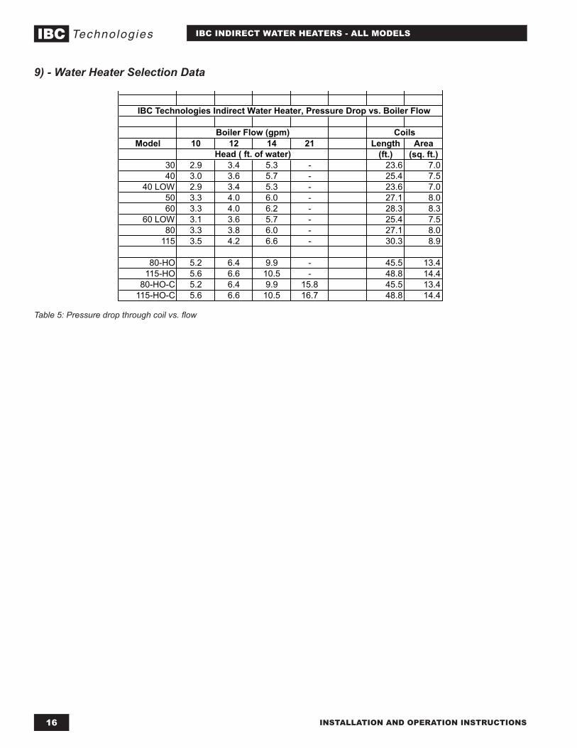
Model 10 12 14 21 Length Area(ft.) (sq. ft.)
30 2.9 3.4 5.3 - 23.6 7.040 3.0 3.6 5.7 - 25.4 7.5
40 LOW 2.9 3.4 5.3 - 23.6 7.050 3.3 4.0 6.0 - 27.1 8.060 3.3 4.0 6.2 - 28.3 8.3
60 LOW 3.1 3.6 5.7 - 25.4 7.580 3.3 3.8 6.0 - 27.1 8.0
115 3.5 4.2 6.6 - 30.3 8.9
80-HO 5.2 6.4 9.9 - 45.5 13.4115-HO 5.6 6.6 10.5 - 48.8 14.4
80-HO-C 5.2 6.4 9.9 15.8 45.5 13.4115-HO-C 5.6 6.6 10.5 16.7 48.8 14.4
Boiler Flow (gpm)
Head ( ft. of water)
Coils
IBC Technologies Indirect Water Heater, Pressure Drop vs. Boiler Flow
9) - Water Heater Selection Data
Table 5: Pressure drop through coil vs. flow
17INSTALLATION AND OPERATION INSTRUCTIONS
IBC INDIRECT WATER HEATERS - ALL MODELS
Heat-Flo, Inc.15 Megan Court, Uxbridge, MA 01569Tel: 508-278-2400 Fax: 508-278-2466
www.heat-flo.com
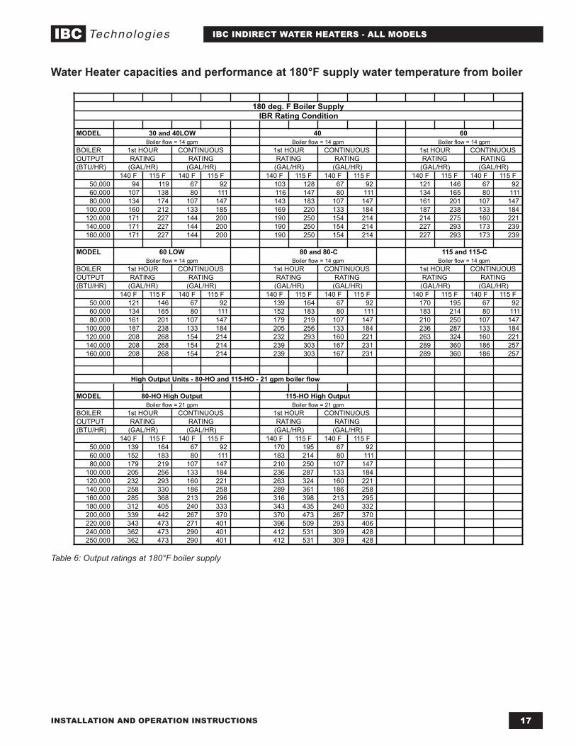
MODEL
BOILEROUTPUT(BTU/HR)
140 F 115 F 140 F 115 F 140 F 115 F 140 F 115 F 140 F 115 F 140 F 115 F50,000 94 119 67 92 103 128 67 92 121 146 67 9260,000 107 138 80 111 116 147 80 111 134 165 80 11180,000 134 174 107 147 143 183 107 147 161 201 107 147
100,000 160 212 133 185 169 220 133 184 187 238 133 184120,000 171 227 144 200 190 250 154 214 214 275 160 221140,000 171 227 144 200 190 250 154 214 227 293 173 239160,000 171 227 144 200 190 250 154 214 227 293 173 239
MODEL
BOILEROUTPUT(BTU/HR)
140 F 115 F 140 F 115 F 140 F 115 F 140 F 115 F 140 F 115 F 140 F 115 F50,000 121 146 67 92 139 164 67 92 170 195 67 9260,000 134 165 80 111 152 183 80 111 183 214 80 11180,000 161 201 107 147 179 219 107 147 210 250 107 147
100,000 187 238 133 184 205 256 133 184 236 287 133 184120,000 208 268 154 214 232 293 160 221 263 324 160 221140,000 208 268 154 214 239 303 167 231 289 360 186 257160,000 208 268 154 214 239 303 167 231 289 360 186 257
MODEL
BOILEROUTPUT(BTU/HR)
140 F 115 F 140 F 115 F 140 F 115 F 140 F 115 F50,000 139 164 67 92 170 195 67 9260,000 152 183 80 111 183 214 80 11180,000 179 219 107 147 210 250 107 147
100,000 205 256 133 184 236 287 133 184120,000 232 293 160 221 263 324 160 221140,000 258 330 186 258 289 361 186 258160,000 285 368 213 296 316 398 213 295180,000 312 405 240 333 343 435 240 332200,000 339 442 267 370 370 473 267 370220,000 343 473 271 401 396 509 293 406240,000 362 473 290 401 412 531 309 428250,000 362 473 290 401 412 531 309 428
(GAL/HR) (GAL/HR) (GAL/HR) (GAL/HR)RATING RATING RATING RATING
(GAL/HR)
Boiler flow = 21 gpm Boiler flow = 21 gpm1st HOUR CONTINUOUS 1st HOUR CONTINUOUS
1st HOUR CONTINUOUS
(GAL/HR) (GAL/HR)
High Output Units - 80-HO and 115-HO - 21 gpm boiler flow
80-HO High Output 115-HO High Output
(GAL/HR) (GAL/HR) (GAL/HR)RATING RATING RATING RATING RATING RATING
1st HOUR CONTINUOUS
60 LOW 80 and 80-C 115 and 115-CBoiler flow = 14 gpm Boiler flow = 14 gpm Boiler flow = 14 gpm
1st HOUR CONTINUOUS
RATING RATING(GAL/HR) (GAL/HR) (GAL/HR) (GAL/HR) (GAL/HR) (GAL/HR)RATING RATING RATING RATING
Boiler flow = 14 gpm Boiler flow = 14 gpm Boiler flow = 14 gpm1st HOUR CONTINUOUS 1st HOUR CONTINUOUS 1st HOUR CONTINUOUS
180 deg. F Boiler Supply
30 and 40LOW 40 60
IBR Rating Condition
Table 6: Output ratings at 180°F boiler supply
Water Heater capacities and performance at 180°F supply water temperature from boiler
INSTALLATION AND OPERATION INSTRUCTIONS18
IBC INDIRECT WATER HEATERS - ALL MODELS
Heat-Flo, Inc.15 Megan Court, Uxbridge, MA 01569Tel: 508-278-2400 Fax: 508-278-2466
www.heat-flo.com
MODEL
BOILEROUTPUT(BTU/HR)
140 F 115 F 140 F 115 F 140 F 115 F 140 F 115 F 140 F 115 F 140 F 115 F50,000 94 119 67 92 103 128 67 92 121 146 67 9260,000 107 138 80 111 116 147 80 111 134 165 80 11180,000 134 174 107 147 143 183 107 147 161 201 107 147
100,000 144 188 117 161 160 208 124 172 187 238 133 184120,000 144 188 117 161 160 208 124 172 187 238 133 184140,000 144 188 117 161 160 208 124 172 187 238 133 184160,000 144 188 117 161 160 208 124 172 187 238 133 184
MODEL
BOILEROUTPUT(BTU/HR)
140 F 115 F 140 F 115 F 140 F 115 F 140 F 115 F 140 F 115 F 140 F 115 F50,000 121 146 67 92 139 164 67 92 170 195 67 9260,000 134 165 80 111 152 183 80 111 183 214 80 11180,000 161 201 107 147 179 219 107 147 210 250 107 147
100,000 178 213 124 159 205 256 133 184 236 287 133 184120,000 178 213 124 159 205 257 133 185 252 310 149 207140,000 178 213 124 159 205 257 133 185 252 310 149 207160,000 178 213 124 159 205 257 133 185 252 310 149 207
MODEL
BOILEROUTPUT(BTU/HR)
140 F 115 F 140 F 115 F 140 F 115 F 140 F 115 F50,000 139 164 67 92 170 195 67 9260,000 152 183 80 111 183 214 80 11180,000 179 219 107 147 210 250 107 147
100,000 205 256 133 184 236 287 133 184120,000 232 293 160 221 263 324 160 221140,000 258 330 186 258 289 361 186 258160,000 285 368 213 296 316 398 213 295180,000 304 393 232 321 341 436 238 333200,000 304 393 232 321 341 446 238 343220,000 304 393 232 321 341 446 238 343240,000 304 393 232 321 341 446 238 343250,000 304 393 232 321 341 446 238 343
(GAL/HR) (GAL/HR) (GAL/HR) (GAL/HR)RATING RATING RATING RATING
(GAL/HR)
Boiler flow = 21 gpm Boiler flow = 21 gpm1st HOUR CONTINUOUS 1st HOUR CONTINUOUS
1st HOUR CONTINUOUS
(GAL/HR) (GAL/HR)
High Output Units - 80-HO and 115-HO - 21 gpm boiler flow
80-HO High Output 115-HO High Output
(GAL/HR) (GAL/HR) (GAL/HR)RATING RATING RATING RATING RATING RATING
1st HOUR CONTINUOUS
60 LOW 80 and 80-C 115 and 115-CBoiler flow = 14 gpm Boiler flow = 14 gpm Boiler flow = 14 gpm
1st HOUR CONTINUOUS
RATING RATING(GAL/HR) (GAL/HR) (GAL/HR) (GAL/HR) (GAL/HR) (GAL/HR)RATING RATING RATING RATING
Boiler flow = 14 gpm Boiler flow = 14 gpm Boiler flow = 14 gpm1st HOUR CONTINUOUS 1st HOUR CONTINUOUS 1st HOUR CONTINUOUS
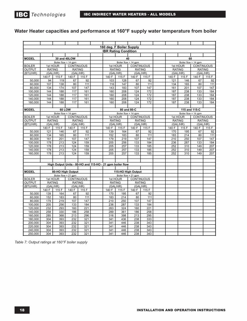
160 deg. F Boiler Supply
30 and 40LOW 40 60
IBR Rating Condition
Table 7: Output ratings at 160°F boiler supply
Water Heater capacities and performance at 160°F supply water temperature from boiler
19INSTALLATION AND OPERATION INSTRUCTIONS
IBC INDIRECT WATER HEATERS - ALL MODELS
DATE LICENSED CONTRACTOR DESCRIPTION OF WORK DONE
Service Record
Notes
IBC Technologies Inc.8015 North Fraser Way Burnaby, BC Canada V5J 5M8
Tel: 604.877.0277 Fax: 604.877.0295
www.ibcboiler.com
120-158A R2