Embed Size (px)
Citation preview

H05
5180
0F
Jandy® Never Lube®
Backwash ValveCovered by the following two U.S. Patents: 6,240,941 and 6,568,428.
Installation and Oper a tion Man u al
Installation and Operation Data
WARNINGFOR YOUR SAFETY - This product must be installed and serviced by authorized personnel qual i fi ed in pool/spa installation and maintenance. Improper installation and/or operation will void the warranty.

Page 2
Table of Contents
Section 1. ... DE and Sand Filters ........................................................................................... 3
Section 2. ... Versa-Coupler Installation ................................................................................. 4
Section 3. ... Normal Operation ............................................................................................... 5
Section 4. ... Backwashing ...................................................................................................... 5
Section 5. ... Vacuuming to Waste (Optional) ........................................................................ 5
Section 6. ... Replacement Parts List ..................................................................................... 7

Page 3
WARNINGEnsure that all electrical power to the system is turned off before approaching, inspecting or troubleshooting any leaking valves that may have caused other electrical devices in the surrounding area to get wet. Failure to do so could result in an electrical hazard that could result in death or serious injury due to electrical shock, and may also cause damage to property.
Section 1. DE and Sand Filters 1. Turn the locking knob on the Never Lube
backwash valve counter clockwise to loosen. Turn the handle back and forth several times to verify the diverters move freely.
2. Turn off all power to the system. For retrofi t installations only, follow steps "a" through "d". For new installations skip steps "a" through "d" and proceed to step 3.
a. Open the pressure relief valve on top of the fi lter. Wait for all air to evacuate the system.
WARNINGNEVER attempt to assemble, dis as sem ble or adjust the fi lter when there is pressurized air in the system. Starting the pump while there is any pressurized air in the system can cause the fi lter lid to be blown off, which can cause death, serious personal injury or property dam age.
b. If the fi lter is below pool level, close the suction and return line valves to isolate the fi ltration system.
c. Remove the drain plug from the fi lter. Let the water drain from the fi lter.
d. Remove the existing valve from the fi lter.
3. Remove the Never Lube backwash valve from packaging.
4. Remove the two (2) O-rings from packaging.
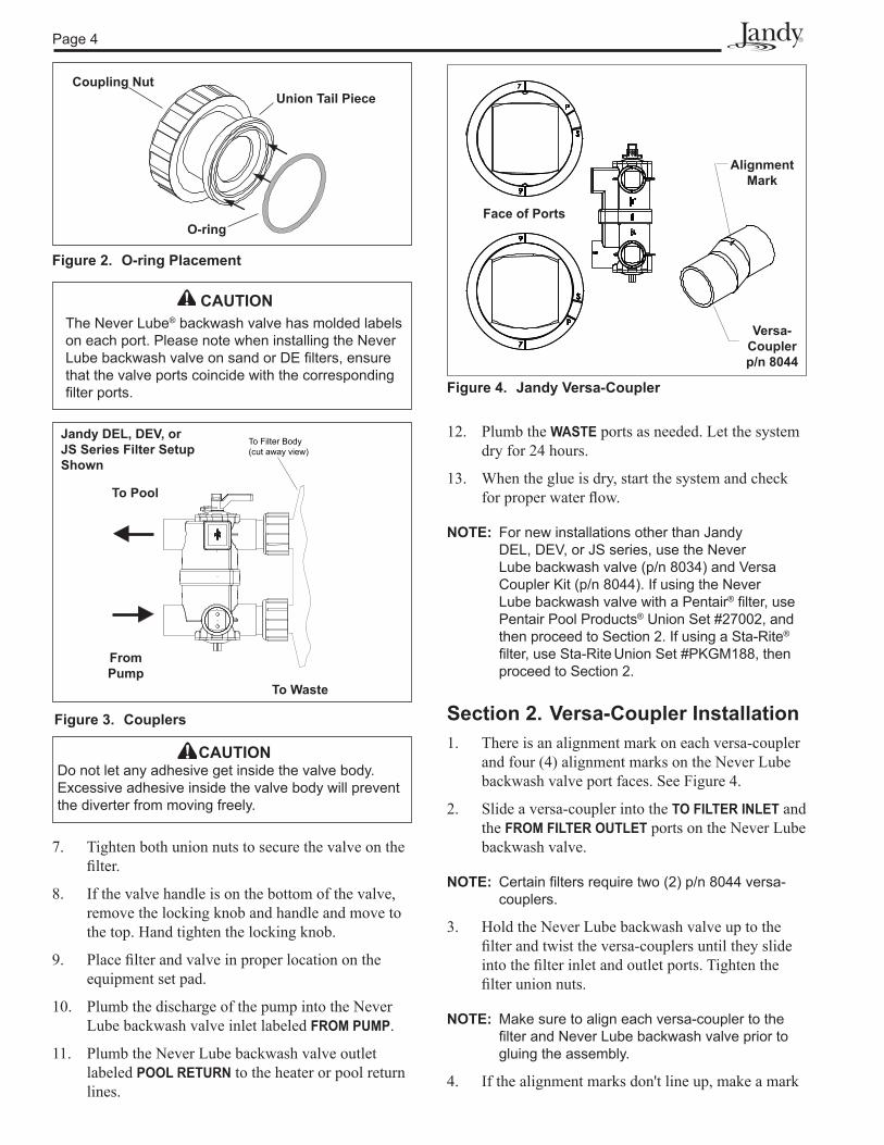
5. Place O-rings on the face of the union tail pieces, where the face of the Never Lube backwash valve union will connect to the fi lter bulkheads. See Figure 2. Make sure each O-ring is properly seated into the groove of each union tail piece.
6. Holding the valve upright, place onto the fi lter bulkheads.
WARNINGFOR YOUR SAFETY: This product must be installed and serviced by a professional pool/spa ser-vice technician. The procedures in this manual must be followed exactly. Improper installation and/or operation will void the warranty.
This document gives instructions for installing a Jandy Never Lube® Backwash Valve. The instructions must be followed exactly. Read through the instructions completely before starting the procedure. Please save these instructions.
The Jandy 2-in-1 Never Lube backwash valve is designed to be used on either sand or diatomaceous earth (DE) fi lters with a center-to-center dimension of 8 inches (center of the inlet port to the center of the outlet port). Used with the Jandy versa-coupler, the Never Lube backwash valve can be used on fi lters with center-to-center dimensions of 7 to 9 inches.
For Jandy Filters, Never Lube backwash valve p/n 8034J comes ready to mount to DEL48 or DEL60 model fi lters (outlet being the top port). If using the 8034J with another model sand or DE fi lter, install per label on valve. BWVL-NVL mounts to DEV48, DEV60, or JS series fi lters. For Pentair®* or Sta-Rite®* fi lters, a combination of p/n 8034 (Never Lube backwash valve) with p/n 8044 (Versa-Coupler Kit) can be used to mount to most models. To mount on a sand fi lter from a manufacturer other than Jandy (with the inlet being the top port), simply fl ip the valve over. If the valve handle ends up on the bottom of the valve, remove the locking knob and handle and place on the top. Hand tighten the locking knob. See Figure 1.
DE Filter Setup Sand Filter Setup
Waste Port
to Top
Waste Port
to Bottom
To Filter Body(cut away view)
To Filter Body(cut away view)
Union Nuts
Figure 1. Handle Positions (DE and Sand)
*Pentair® and Sta-Rite® are registered trademarks of Pentair, Inc and its as-sociated companies.
Page 4
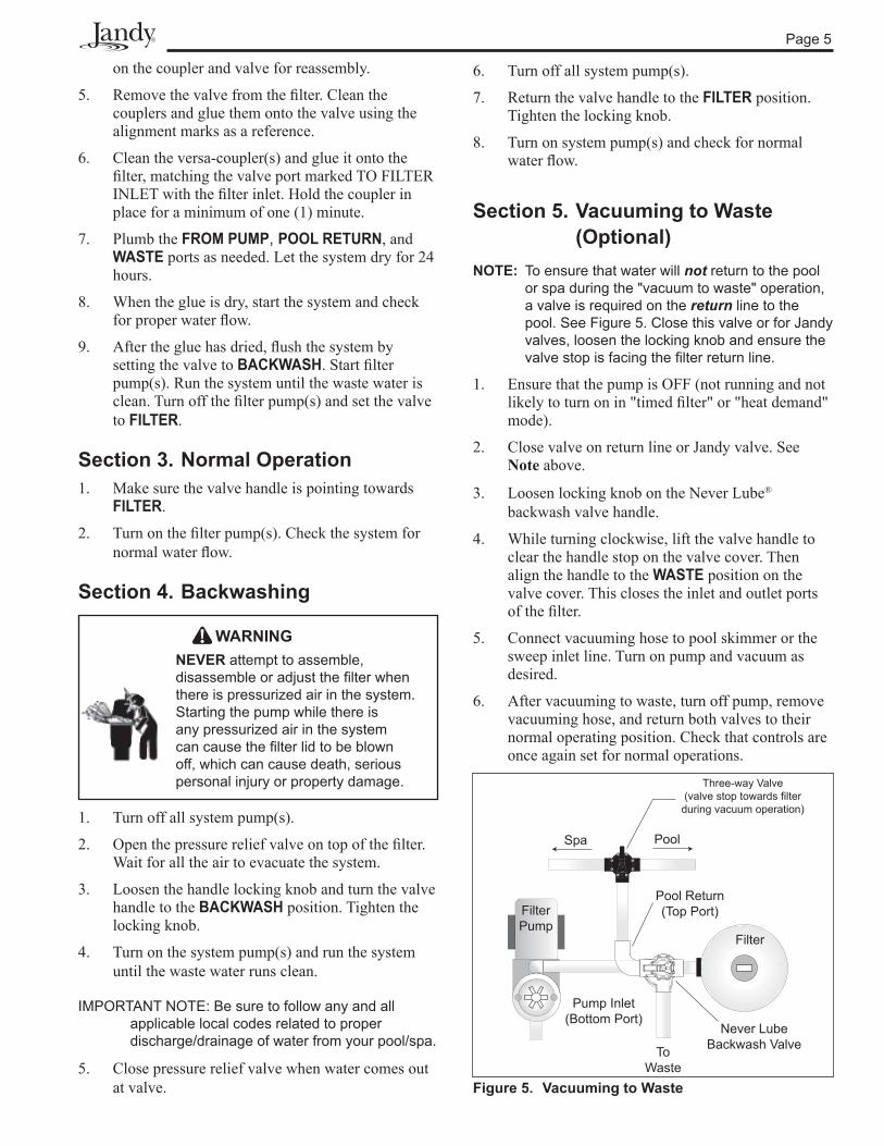
Figure 4. Jandy Versa-Coupler
Alignment Mark
Versa-Coupler p/n 8044
Face of Ports
CAUTIONDo not let any adhesive get inside the valve body. Excessive adhesive inside the valve body will prevent the diverter from moving freely.
Figure 3. Couplers
To Filter Body(cut away view)
Jandy DEL, DEV, or JS Series Filter Setup Shown
To Pool
To Waste
FromPump
CAUTIONThe Never Lube® backwash valve has molded labels on each port. Please note when installing the Never Lube backwash valve on sand or DE fi lters, ensure that the valve ports coincide with the corresponding fi lter ports.
7. Tighten both union nuts to secure the valve on the fi lter.
8. If the valve handle is on the bottom of the valve, remove the locking knob and handle and move to the top. Hand tighten the locking knob.
9. Place fi lter and valve in proper location on the equipment set pad.
10. Plumb the discharge of the pump into the Never Lube backwash valve inlet labeled FROM PUMP.
11. Plumb the Never Lube backwash valve outlet labeled POOL RETURN to the heater or pool return lines.
12. Plumb the WASTE ports as needed. Let the system dry for 24 hours.
13. When the glue is dry, start the system and check for proper water fl ow.
NOTE: For new installations other than Jandy DEL, DEV, or JS series, use the Never Lube backwash valve (p/n 8034) and Versa Coupler Kit (p/n 8044). If using the Never Lube backwash valve with a Pentair® fi lter, use Pentair Pool Products® Union Set #27002, and then proceed to Section 2. If using a Sta-Rite® fi lter, use Sta-Rite Union Set #PKGM188, then proceed to Section 2.
Section 2. Versa-Coupler Installation1. There is an alignment mark on each versa-coupler
and four (4) alignment marks on the Never Lube backwash valve port faces. See Figure 4.
2. Slide a versa-coupler into the TO FILTER INLET and the FROM FILTER OUTLET ports on the Never Lube backwash valve.
NOTE: Certain fi lters require two (2) p/n 8044 versa- couplers.
3. Hold the Never Lube backwash valve up to the fi lter and twist the versa-couplers until they slide into the fi lter inlet and outlet ports. Tighten the fi lter union nuts.
NOTE: Make sure to align each versa-coupler to the fi lter and Never Lube backwash valve prior to gluing the assembly.
4. If the alignment marks don't line up, make a mark
Figure 2. O-ring Placement
Coupling Nut
O-ring
Union Tail Piece
Page 5
on the coupler and valve for reassembly.
5. Remove the valve from the fi lter. Clean the couplers and glue them onto the valve using the alignment marks as a reference.
6. Clean the versa-coupler(s) and glue it onto the fi lter, matching the valve port marked TO FILTER INLET with the fi lter inlet. Hold the coupler in place for a minimum of one (1) minute.
7. Plumb the FROM PUMP, POOL RETURN, and WASTE ports as needed. Let the system dry for 24 hours.
8. When the glue is dry, start the system and check for proper water fl ow.
9. After the glue has dried, fl ush the system by setting the valve to BACKWASH. Start fi lter pump(s). Run the system until the waste water is clean. Turn off the fi lter pump(s) and set the valve to FILTER.
Section 3. Normal Operation1. Make sure the valve handle is pointing towards
FILTER.
2. Turn on the fi lter pump(s). Check the system for normal water fl ow.
Section 4. Backwashing
WARNINGNEVER attempt to assemble, dis as sem ble or adjust the fi lter when there is pressurized air in the system. Starting the pump while there is any pressurized air in the system can cause the fi lter lid to be blown off, which can cause death, serious personal injury or property dam age.
1. Turn off all system pump(s).
2. Open the pressure relief valve on top of the fi lter. Wait for all the air to evacuate the system.
3. Loosen the handle locking knob and turn the valve handle to the BACKWASH position. Tighten the locking knob.
4. Turn on the system pump(s) and run the system until the waste water runs clean.
IMPORTANT NOTE: Be sure to follow any and all applicable local codes related to proper discharge/drainage of water from your pool/spa.
5. Close pressure relief valve when water comes out at valve. Figure 5. Vacuuming to Waste
6. Turn off all system pump(s).
7. Return the valve handle to the FILTER position. Tighten the locking knob.
8. Turn on system pump(s) and check for normal water fl ow.
Section 5. Vacuuming to Waste (Optional)
NOTE: To ensure that water will not return to the pool or spa during the "vacuum to waste" operation, a valve is required on the return line to the pool. See Figure 5. Close this valve or for Jandy valves, loosen the locking knob and ensure the valve stop is facing the fi lter return line.
1. Ensure that the pump is OFF (not running and not likely to turn on in "timed fi lter" or "heat demand" mode).
2. Close valve on return line or Jandy valve. See Note above.
3. Loosen locking knob on the Never Lube® backwash valve handle.
4. While turning clockwise, lift the valve handle to clear the handle stop on the valve cover. Then align the handle to the WASTE position on the valve cover. This closes the inlet and outlet ports of the fi lter.
5. Connect vacuuming hose to pool skimmer or the sweep inlet line. Turn on pump and vacuum as desired.
6. After vacuuming to waste, turn off pump, remove vacuuming hose, and return both valves to their normal operating position. Check that controls are once again set for normal operations.
Spa Pool
Filter Pump
Filter
Pool Return(Top Port)
Pump Inlet(Bottom Port)
ToWaste
Never LubeBackwash Valve
Three-way Valve(valve stop towards filter
during vacuum operation)
Page 6
0
1
2
3
4
5
6
Flow Rate (gpm)
Des
ign
Hea
d Lo
ss
(feet
hea
d)
Des
ign
Pres
sure
D
rop
(psi
)
0 20 40 60 80 100 1200.0
0.5
1.0
1.5
2.0
2.5
140
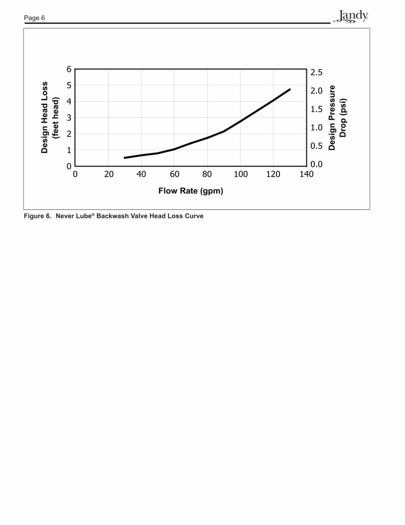
Figure 6. Never Lube® Backwash Valve Head Loss Curve
Page 7
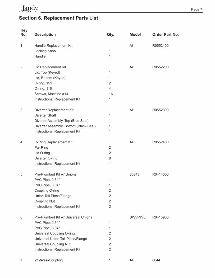
Section 6. Replacement Parts List
KeyNo. Description Qty. Model Order Part No.
1 Handle Replacement Kit All R0552100Locking Knob 1Handle 1
2 Lid Replacement Kit All R0552200Lid, Top (Keyed) 1Lid, Bottom (Keyed) 1O-ring, 151 2O-ring, 116 4Screws, Machine #14 16Instructions, Replacement Kit 1
3 Diverter Replacement Kit All R0552300Diverter Shaft 1Diverter Assembly, Top (Blue Seal) 1Diverter Assembly, Bottom (Black Seal) 1Instructions, Replacement Kit 1
4 O-Ring Replacement Kit All R0552400Par Ring 2Lid O-ring 2Diverter O-ring 8Instructions, Replacement Kit 1
5 Pre-Plumbed Kit w/ Unions 8034J R0414000 PVC Pipe, 2.54" 1PVC Pipe, 3.04" 1Coupling O-ring 2Union Tail Piece/Flange 2Coupling Nut 2Instructions, Replacement Kit 2
6 Pre-Plumbed Kit w/ Universal Unions BWV-NVL R0413900PVC Pipe, 2.54" 1PVC Pipe, 3.04" 1Universal Coupling O-ring 2Universal Union Tail Piece/Flange 2Universal Coupling Nut 2Instructions, Replacement Kit 2
7 2" Versa-Coupling 1 All 8044

Page 8
4 "38
½"
Front View
8"14¾"
Top View
8 "58
Versa-Coupler(2" PVC pipe size p/n 8044,
qty. 1)
Right Side View
6¾"
4
3
4
1
4
4
2
2
3
2
5, 6
3.04"
2.54"

Page 9
Notes

Page 10
Notes

Page 11
Notes
H05
5180
0F
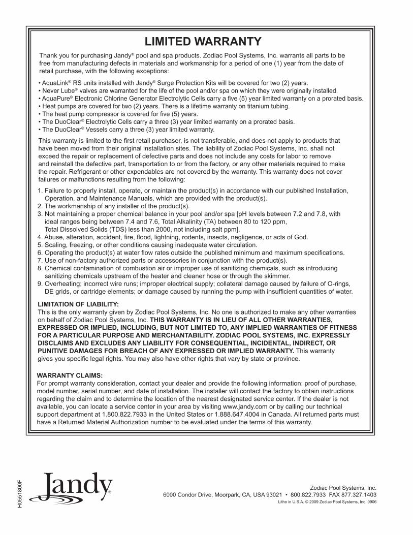
This warranty is limited to the first retail purchaser, is not transferable, and does not apply to products that have been moved from their original installation sites. The liability of Zodiac Pool Systems, Inc. shall not exceed the repair or replacement of defective parts and does not include any costs for labor to remove and reinstall the defective part, transportation to or from the factory, or any other materials required to make the repair. Refrigerant or other expendables are not covered by the warranty. This warranty does not cover failures or malfunctions resulting from the following:
LIMITED WARRANTY
• AquaLink® RS units installed with Jandy® Surge Protection Kits will be covered for two (2) years.• Never Lube® valves are warranted for the life of the pool and/or spa on which they were originally installed.• AquaPure® Electronic Chlorine Generator Electrolytic Cells carry a five (5) year limited warranty on a prorated basis.• Heat pumps are covered for two (2) years. There is a lifetime warranty on titanium tubing.• The heat pump compressor is covered for five (5) years.• The DuoClear® Electrolytic Cells carry a three (3) year limited warranty on a prorated basis.• The DuoClear® Vessels carry a three (3) year limited warranty.
1. Failure to properly install, operate, or maintain the product(s) in accordance with our published Installation, Operation, and Maintenance Manuals, which are provided with the product(s).2. The workmanship of any installer of the product(s).3. Not maintaining a proper chemical balance in your pool and/or spa [pH levels between 7.2 and 7.8, with ideal ranges being between 7.4 and 7.6, Total Alkalinity (TA) between 80 to 120 ppm, Total Dissolved Solids (TDS) less than 2000, not including salt ppm].4. Abuse, alteration, accident, fire, flood, lightning, rodents, insects, negligence, or acts of God.5. Scaling, freezing, or other conditions causing inadequate water circulation.6. Operating the product(s) at water flow rates outside the published minimum and maximum specifications.7. Use of non-factory authorized parts or accessories in conjunction with the product(s).8. Chemical contamination of combustion air or improper use of sanitizing chemicals, such as introducing sanitizing chemicals upstream of the heater and cleaner hose or through the skimmer.9. Overheating; incorrect wire runs; improper electrical supply; collateral damage caused by failure of O-rings, DE grids, or cartridge elements; or damage caused by running the pump with insufficient quantities of water.
LIMITATION OF LIABILITY:This is the only warranty given by Zodiac Pool Systems, Inc. No one is authorized to make any other warranties on behalf of Zodiac Pool Systems, Inc. THIS WARRANTY IS IN LIEU OF ALL OTHER WARRANTIES, EXPRESSED OR IMPLIED, INCLUDING, BUT NOT LIMITED TO, ANY IMPLIED WARRANTIES OF FITNESS FOR A PARTICULAR PURPOSE AND MERCHANTABILITY. ZODIAC POOL SYSTEMS, INC. EXPRESSLY DISCLAIMS AND EXCLUDES ANY LIABILITY FOR CONSEQUENTIAL, INCIDENTAL, INDIRECT, OR PUNITIVE DAMAGES FOR BREACH OF ANY EXPRESSED OR IMPLIED WARRANTY. This warranty gives you specific legal rights. You may also have other rights that vary by state or province.
WARRANTY CLAIMS:For prompt warranty consideration, contact your dealer and provide the following information: proof of purchase, model number, serial number, and date of installation. The installer will contact the factory to obtain instructions regarding the claim and to determine the location of the nearest designated service center. If the dealer is not available, you can locate a service center in your area by visiting www.jandy.com or by calling our technical support department at 1.800.822.7933 in the United States or 1.888.647.4004 in Canada. All returned parts must have a Returned Material Authorization number to be evaluated under the terms of this warranty.
Thank you for purchasing Jandy® pool and spa products. Zodiac Pool Systems, Inc. warrants all parts to be free from manufacturing defects in materials and workmanship for a period of one (1) year from the date of retail purchase, with the following exceptions:
Zodiac Pool Systems, Inc.6000 Condor Drive, Moorpark, CA, USA 93021 • 800.822.7933 FAX 877.327.1403
Litho in U.S.A. © 2009 Zodiac Pool Systems, Inc. 0906