Embed Size (px)
Citation preview

For contractors
Please read carefully prior to installation and servicing.
CAUTION!Observe the safety instructions of this installation and maintenance manual before placing the boiler in operation.
DANGER! If installation, adjustment, modification, operation or maintenance of the heating system is carried out by an unqualified person, this may result in danger to life and limb or property damage.The directions of this installation and maintenance manual must be followed precisely.If you require assistance or further information, con-tact a qualified installer or an appropriate service provider.
CAUTION!The operating manual is a component of the techni-cal documentation and must be handed over to the operator of the heating system. Discuss the instruction in this manual with the ow-ner or operator of the heating system to ensure that they are familiar with all information required for operation of the heating system.
Installation and Maintenance Instructions
Oil condensing boiler
Logano GB125 BE US/CA
6 72
0 64
7 54
8 - 0
1/20
11 U
S/C
A

Contents
Logano GB125 BE US/CA - Subject to technical modifications.2
Contents
1 Safety instructions and explanation ofsymbols 3
1.1 Safety instructions 31.2 Explanation of symbols 4
2 Product description 52.1 Intended use 52.2 Standards, regulations and code compliance 52.3 Notes on installation and operation 52.4 Product description 62.5 Boiler water quality 72.6 Tools, Materials and Accessories 72.7 Scope of delivery 72.8 Dimensions and specifications 82.9 Conditions for operation 92.9.1 General operating conditions 92.9.2 Conditions for the boiler room
and the environment 102.9.3 Fuel conditions 102.9.4 Power supply conditions 102.9.5 Conditions for hydraulic system and water quality 112.10 Disposal 11
3 Moving the boiler 123.1 Reducing the boiler weight for handling purposes 123.2 Lifting and carrying the boiler 133.3 Moving the boiler with hand truck 13
4 Placing the boiler 144.1 Wall clearances 144.2 Reversing the burner door 154.3 Mounting the adjustable feet (included with B-kit) 164.4 Positioning and leveling the boiler 16
5 Installing the boiler 175.1 Flue pipe installation 175.2 Test ports 185.3 Installation options 205.4 Making the water connections 225.4.1 Installing B-kit 225.4.2 Mounting the drain valve (included with B-kit) 235.4.3 Installation of system components 235.5 Filling the heating system and checking for leaks 245.6 Connecting the fuel supply 255.7 Bleed off condensate 265.8 Electrical supply connections 275.8.1 Installing the control panel 275.8.2 Installing the temperature sensor assembly 285.8.3 Power connection and connections of additional
components 295.8.4 Installing cable strain relief 305.9 Installing the back boiler cover 30
6 Starting up the heating system 316.1 Bringing the system up to operating pressure 316.2 Testing safety valve 326.3 Checking position of heat exchanger baffles 326.4 Preparing the heating system for operation 326.5 Starting up the control panel and the burner 336.6 Taking measurements 336.7 Checking the manual reset high limit (STB) 346.8 Installing the burner hood 346.9 Commissioning log 35
7 Shutting down the heating system 367.1 Normal shut-down 367.2 Shutting down the heating system in an
emergency 367.2.1 Action in an emergency 36
8 Heating system inspection 378.1 Why is regular maintenance important? 378.2 Preparing the boiler for inspection 378.3 Cleaning the boiler 388.3.1 Cleaning the boiler with cleaning brushes 388.3.2 Wet cleaning (chemical cleaning) 398.4 Cleaning the heat exchanger system 408.5 Cleaning the neutralization and siphon 428.6 Checking the air supply hose 438.7 Check heating system operating pressure 438.8 Test safety valve 448.9 Concentric supply air and flue gas routing 448.10 Air supply system 448.11 Inspection and maintenance reports 45
9 Troubleshooting 48
10 Examples of installations 49
11 Spare parts 52
12 Wiring diagrams 60
Index 61

1Safety instructions and explanation of symbols
Logano GB125 BE US/CA - Subject to technical modifications. 3
1 Safety instructions and explanation of symbols
1.1 Safety instructions
If you smell flue gasB Switch off the boiler ( page 36).B Open windows and doors.B Inform an authorized heating contractor.
Risk of poisoning. An insufficient supply of air can result in dangerous escape of flue gas.B Never close off or reduce the size of air intake and
outlet openings.B The boiler must not be operated until the obstruction
has been removed.B Ensure that no mechanical air-extraction equipment
draws air from the boiler room, e.g. kitchen vent hood, clothes dryer, central vacuum system, etc.
B Inform the system user in writing of an existing problem and associated dangers.
Danger from escaping flue gasesB Make sure that the vent pipes and gaskets are not
damaged.B Use silicone as sealing compound.B Never operate this boiler with a barometric or a
thermally-controlled vent damper.B Connect only one boiler to each venting system or
chimney flue.B The venting system piping must not feed into another
air extraction duct. B Do not route the venting system piping through or
inside another duct used for exhaust air or other flue gases.
B To prevent the combustion gases from reaching the boiler room, the siphon must always be filled with water.
Dangers posed by explosive and combustible materialsB Do not use or store easily-combustible materials
(paper, lace curtains, clothing, thinners, paints, etc.) near the boiler.
B Maintain a clearance of 16 inches (40.6 cm) from the boiler.
Combustion airB Keep the supply of combustion air free of corrosive
substances (e.g. halogenated hydrocarbons that contain chlorine or fluorine compounds). This will help prevent corrosion.
Danger from electrical shockB Before opening the boiler:
Disconnect the heating system from the electrical power supply by means of the emergency shutoff switch or the heating system circuit breaker on the main fuse panel.
B It is not sufficient just to switch off the control panel.B Take measures to ensure that the heating system
cannot be switched on again unintentionally.
InstallationB Correct and proper installation and adjustment of the
burner and the control panel are the fundamental requirements for safe and economical operation of the boiler.
B The boiler may only be installed or maintained by an approved heating contractor.
B Do not modify any parts that carry flue gases.B Only qualified electricians are permitted to carry out
electrical work. Follow applicable code.B The hot water tank may only be used for heating
domestic hot water.B Never shut off safety valves!
Water may escape from the safety valve when it is being heated.
Danger due to failing to consider your own safety in an emergency such as a fireB Never put yourself at risk of fatal injury. Your own safety
must always take the highest priority.
1 Safety instructions and explanation of symbols
Logano GB125 BE US/CA - Subject to technical modifications.4
Inspection/maintenanceHeating systems must be maintained regularly.
This way, they maintain a high level of efficiency and low fuel consumption.
You will achieve a high level of operational safety.
And you will obtain the cleanest possible combustion.
B Recommendation for customers: take out a maintenance and inspection contract with an approved heating contractor covering annual inspection and condition-based maintenance.
B Maintenance and repairs may only be carried out by an approved heating contractor.
B Have any faults corrected immediately in order to prevent damage to the system.
B Use only genuine spare parts. Damage caused by the use of parts not supplied by Buderus is not covered by the Buderus warranty.
Instructing the customerB Explain to the customer how the boiler works and how
to operate it.B Inform the customer that he/she must not carry out any
alterations or repairs.
1.2 Explanation of symbols
Signal words are used to indicate the seriousness of the ensuing risk if measures for minimizing damage are not taken.
• Caution indicates that minor damage to property may occur.
• Warning means that minor injury or severe property damage may occur.
• Danger means that severe injury may occur. Very serious cases may result in death.
Notes contain important additional information.
Notes do not contain any warnings or information about hazards or risks.
Cross-references to particular places in the document or to other documents are marked with an arrow .
Warnings are indicated by a warning triangle and a gray background.
Notesare identified in the text by this symbol. They are separated by horizontal lines above and below the text.

2Product description
Logano GB125 BE US/CA - Subject to technical modifications. 5
2 Product descriptionThis installation and maintenance manual contains important information for the safe and correct installation, initial start-up and maintenance of this boiler.
The Logano GB125 BE oil-fired condensing boiler is generally referred to below simply as the boiler.
These installation and maintenance instructions are designed for specialists, who – through their vocational training and experience –are knowledgeable in handling heating systems and DHW installations.
This boiler must only be installed with one of the Buderus supplied concentric supply air and flue gas routing systems.
• Concentric air supply and flue pipe exiting through external wall
• Concentric supply air and flue gas routing via roof• Concentric supply air/flue gas routing through a flue
inside a duct
This boiler produces significant amounts of acidic flue gas condensate while in operation. Condensate may cause damage to sewer pipes and septic systems, and disposal may be subject to local regulations. In the absence of such regulations Buderus recommends a condensate neutralization kit.
The boiler must draw all combustion air from the outside.
2.1 Intended useThe boiler is designed for the central heating and indirect heating of domestic hot water (e.g. in a hot water tank), for instance in single family homes or multi-family buildings.
2.2 Standards, regulations and code compliance
2.3 Notes on installation and operationWhen installing and operating the heating system observe the following:
• The local building codes regarding the installation• The local building codes regarding combustion air
supply and venting systems, and the chimney connection
• Regulations governing power connection to the power supply
• The regulations and standards relating to the safety systems for the water heating system
Other important information• Only operate the boiler with the combined combustion
air/flue venting system specifically designed and approved for it.
• Follow the local code when connecting the condensate outlet to the public sewer system.
It is the installer's responsibility to ensure the installation and operation of this heating system meets all applicable federal, state, and local codes.
The boiler must be installed by a qualified installer and in accordance with all requirements of NFPA-31, "Installation of Oil-Burning Equipment". Installation must comply with all local and national legal requirements and the regulations of all institutions having legislative authority with regard to the installation of oil-fired boilers.For Canada, the guidelines of the CSA/CGA B139 Installation Code apply.

2 Product description
Logano GB125 BE US/CA - Subject to technical modifications.6
2.4 Product descriptionThis boiler is an oil-fired condensing boiler with modulating control of boiler water temperature.
The boiler consists of:• Control panel• Boiler casing• Boiler block with thermal insulation• Burner • Heat exchanger system
The control panel monitors and controls all electrical boiler components.
The boiler casing prevents heat loss and reduces noise.
The boiler block transfers the heat generated by the burner to the boiler water. The insulation prevents energy loss.
Fig. 1 Boiler with burner
1 Control panel2 Boiler casing3 Boiler block with thermal insulation4 Burner hood5 Burner
Fig. 2 Rear view with heat exchanger (thermal insulation not shown)
1 Heat exchanger system

2Product description
Logano GB125 BE US/CA - Subject to technical modifications. 7
2.5 Boiler water qualityPoor water quality can damage heating systems due to scale formation and corrosion. (Tab. 8, page 11).
2.6 Tools, Materials and AccessoriesFor the installation and maintenance of the boiler, you need standard tools used for central heating and DHW systems, plus metric wrenches and metric Allen wrenches.
The following may also prove useful:• Hand truck with securing strap or Buderus boiler cart• Wood battens• Cleaning brushes and/or chemical cleaning agent for
wet cleaning
2.7 Scope of deliveryB After delivery, check all packaging for perfect
condition.B Check the delivery for completeness.
CAUTION: Risk of system damage due to unsuitable boiler water!B When using oxygen-permeable pipes, e.
g. for radiant floor heating systems, you must separate the system using heat exchangers. Unsuitable heating system water promotes sludge formation and corrosion. This can result in heat exchanger malfunction and damage.
Component Qty Packaging
Boiler block 1 1 pallet
Boiler casing, factory-installed on the boiler block
Burner hood, factory-installed on the boiler block
Heat exchanger system, factory-installed on the boiler block
Oil burner with factory-installed burner door
Air supply hose, factory-installed
Siphon 1 1 bag1)
1) Under the burner hood
B-kit components:• Conversion nipple
(1¼ " NPT)• 30 psi safety valve• Drain valve (¾ ")• Pressure/temperature
gauge• Double nipple
(1¼ " NPT × R1¼ )• 90°-elbow (1¼ ” NPT)• 90°-elbow (¾ " NPT)• Screw set (for burner
mounting)• Adjustable feet
1 1 foil package1)
Control panel 1 1 box
Tigerloop oil filter and de-aerator
1 1 box
Technical documentation 1 bag
Tab. 1 Scope of delivery
2 Product description
Logano GB125 BE US/CA - Subject to technical modifications.8
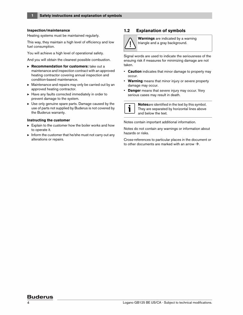
2.8 Dimensions and specifications
Fig. 3 Connections and dimensions (measurements in inches)
VK = Boiler supplyRK = Boiler returnEL = Boiler drain (connection for drain valve)
Dimensions and connections:
Boiler type Unit GB125/22 BE GB125/30 BE GB125/35 BE
Boiler sections 3 4 4
Rated heat output (gross output)
131/86 °F
MBtu/hr 76 102 124
Rated heat output (net IBR rating)
131/86 °F
MBtu/hr 67 90 109
Rated heat output/heating capacity
(gross output)176/140 °F
MBtu/hr 75 100 121
Rated heat output
(net IBR rating)176/140 °F
MBtu/hr 65 87 105
Rated thermal input/burner input MBtu/hr 81 108 131
AFUE % 91.2 91.1 91.0
Flue gas temperature 176/140 °F °F (°C) 176 (80) 176 (80) 192 (89)
Boiler water content gal (l) 8.7 (35.6) 11.8 (44.9) 11.8 (44.9)
Gas volume of combustion chamber and heat
exchanger
cu. ft.
(l)
1.5 (42.9) 2.0 (57.9) 2.0 (57.9)
Oil consumption/oil firing rate gph (l/h) 0.60 (2.3) 0.75 (2.9) 0.95 (3.6)
Flue gas resistance in. W.C.
(Pa)
0.08" - 0.14" W.C. (20 - 35)
Heat exchanger water pressure drop
(DeltaT = 18 °F)
ft. of
head
(mbar)
1.8' (54) 2.0' (60) 2.7' (81)
Maximum supply temperature1)
1) Safety limit (manual reset high limit, STB)Maximum permitted supply temperature = manual reset high limit (STB) – 32 °FExample: manual reset high limit (STB) = 212 °F, maximum possible supply temperature = 212 - 32 = 180 °FThe safety limit must comply with the requirements applicable in your country.
°F (°C) 212 (100)
Maximum operating pressure psi (bar) 44 (3)
Maximum time constant of thermostat and
manual reset high limit (STB)
s 40
Tab. 2 Technical specifications

2Product description
Logano GB125 BE US/CA - Subject to technical modifications. 9
2.9 Conditions for operationMaintaining the specified operating conditions will enable the boiler to provide a high level of reliability and long service life. Some details relate only to operation with Logamatic control panels from Buderus.
2.9.1 General operating conditions
Boiler type Unit GB125/22 BE GB125/30 BE GB125/35 BE
Boiler overall length (L) Inches 37 1/2" 42 3/8" 42 3/8"
Boiler block length (LK) Inches 25 3/4" 30 1/2" 30 1/2"
Combustion chamber length Inches 16" 20 1/2" 20 1/2"
Combustion chamber length Inches 10 5/8"
Burner door thickness Inches 2 1/3"
Distance between boiler feet (FL) Inches 16 1/8" 20 7/8" 20 7/8"
Net weight1) lbs 423 503 503
Tab. 3 Dimensions, weight and other data for boilers with burners1) Weight incl. packaging material approx. 6-8 % more.
CAUTION: Risk of system damage if operating conditions are not maintained.Extreme divergence from the stated conditions may cause irreversible damage to individual components of the boiler.
B The information on the rating plate is definitive.
Operating conditions
Min. boiler water tempera-
ture
Operating interruption
(complete boiler shutdown)
Heating zone with
heating zone mixing valve1) Min. return temperature
In combination with Logamatic control panel for variable low-temperature operating modes, such as Logamatic 2107.
No requirements. Operating
temperatures are safeguarded
by the Logamatic control
panel. 2)
Automatically by Logamatic control
panel
Not required but recommended with
low-temperature heating system design
130/113 °F.
Required with:
• Radiant floor heating system
• Systems with large water capacity:
> 115 gal/MBH
(1 MBH = 100,000 Btu/hr)
No requirements
Tab. 4 General operating conditions1) A heating zone with a mixing valve improves controllability and is specifically recommended for systems with several heating zones.
2) If the control panel does not influence the heating zones or a heating zone actuating component (e.g. Pumplogic), the burner ON mode must reach an operating temperature of 122 °F within 10 min by restricting volume flow.
2 Product description
Logano GB125 BE US/CA - Subject to technical modifications.10
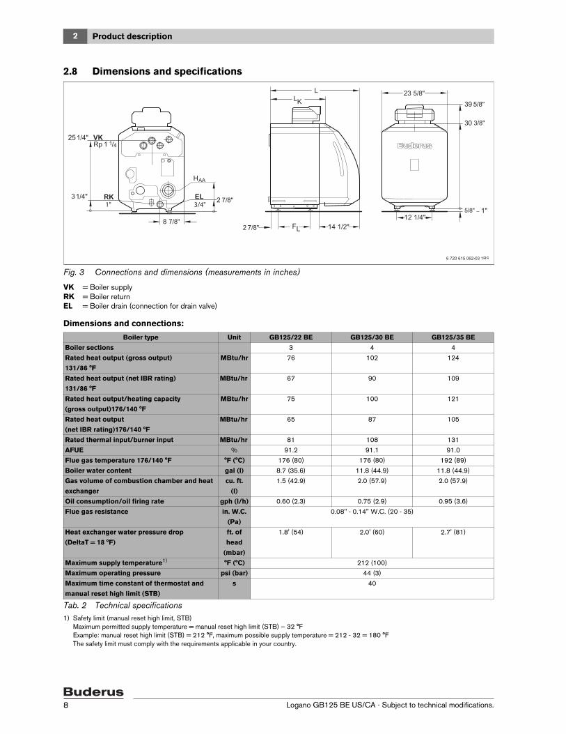
2.9.2 Conditions for the boiler room and the environment
2.9.3 Fuel conditions
2.9.4 Power supply conditions
Operating conditions Notes – Requirement in greater detail
Temperature in the boiler room 40 to 104 °F
(5 to 40 °C)
Relative humidity max. 90 % No condensation or precipitation inside the boiler room
Dust/airborne particles − Excessive dust inside the boiler room must be avoided when the boiler is operat-
ing, e.g.:
• Dust from building work
Combustion air supplied from outside must not be excessively loaded with dust
or airborne seed; if necessary, air filters should be installed to prevent this:
• Air supply contaminated with dust from dirt roads and paths.
• Air supply contaminated with dust from production and processing facilities, e.g. quar-
ries, mines, etc.
• Airborne particles from thistles and similar
Halogenated-hydrocarbon com-
pounds
− The combustion air must be free from halogen-hydrocarbon compounds.
• Identify the source of halogen-hydrocarbon compounds and seal it off. Where this is
impossible, route combustion air from areas that are not contaminated by halogen-
hydrocarbon compounds.
Small animals − Prevent small animals from entering the boiler room, particularly through the air inlet vents –
by installing screens.
Fire safety − Maintain clearances between the boiler and flammable materials in accordance with local
regulations. A minimum clearance of 16” is required. Never store flammable materials or liq-
uids in the vicinity of the boiler.
Flooding − In case of an acute risk of flooding, disconnect the boiler in time from its fuel and power
supply before water enters the room. Any general and burner components or control equip-
ment that comes into contact with water must be replaced before starting up again.
Tab. 5 Boiler room and ambient conditions
Country All countries
Fuels #2 Fuel oil ASTM D396-05 Type 2
Approved for B5 Fuel Oil (5% biodiesel (B100) according ASTM D6751)
Remarks The burner may only be operated with the specified fuel.
Clean and service once a year. Check that the entire system functions properly at the same time. Immediately
remedy faults.
Tab. 6 Country-specific fuels and remarks
Operating conditions Notes – Requirement in greater detail
Line voltage 110 – 120 V The outer casing/boiler must be grounded to protect people and in order to function correctly.
Circuit breaker 10 A
Frequency 60 Hz
Protection class − IP 40 (protected against contact by entry of foreign objects > 0.04 inches Ø (> 1 mm Ø ), no
waterproofing)
Tab. 7 Power supply

2Product description
Logano GB125 BE US/CA - Subject to technical modifications. 11
2.9.5 Conditions for hydraulic system and water quality
2.10 DisposalB Dispose of boiler packaging in an environmentally-
responsible manner.B All heating system components that have to be
replaced should be disposed of in environmentally-responsible manner at an authorized disposal site.
Operating conditions Notes – Requirement in greater detail
Operating pressure (above atmo-
spheric)
15 – 44 psi
(1 to 3 bar)
Maximum 30 psi with the supplied safety valve.
Permissible test pressure 45 – 58 psi
(3 to 4 bar)
Safety temperature limitation by TR
temperature controller
122 – 194 °F
(50 to 90 °C)
Safety temperature limitation by man-
ual reset high limit (STB)
212 °F
(100 °C)
Water quality − The heating system may only be filled and topped up with water of domestic water qual-
ity. We recommend a pH level of 8.2 – 9.5.
Tab. 8 Hydraulics and water quality

3 Moving the boiler
Logano GB125 BE US/CA - Subject to technical modifications.12
3 Moving the boilerThis section details how to move the boiler safely.
3.1 Reducing the boiler weight for handling purposesIf required, you can reduce the weight of the boiler by removing the burner hood and door.B Unscrew the burner hood screws.B Lift burner hood slightly and pull forwards to remove.B Before removing the burner door: unplug the burner
plug from the burner controller.
Fig. 4 Removing burner hood
B Unscrew two hex bolts at the sides.B Open the boiler door.B Lift the burner door off its hinges.
Fig. 5 Removing the burner door
CAUTION: Risk of system damage from impact shocks!Fragile components could be damaged.
B Follow the transport instructions on the packaging.
Protect connectors against contamination if the boiler is not immediately put into operation.
Dispose of packaging in an environmentally-responsible manner.
Prevent the burner door from falling over and damaging the burner and burner tube.
7 747 019 141-04.1RS
3Moving the boiler
Logano GB125 BE US/CA - Subject to technical modifications. 13
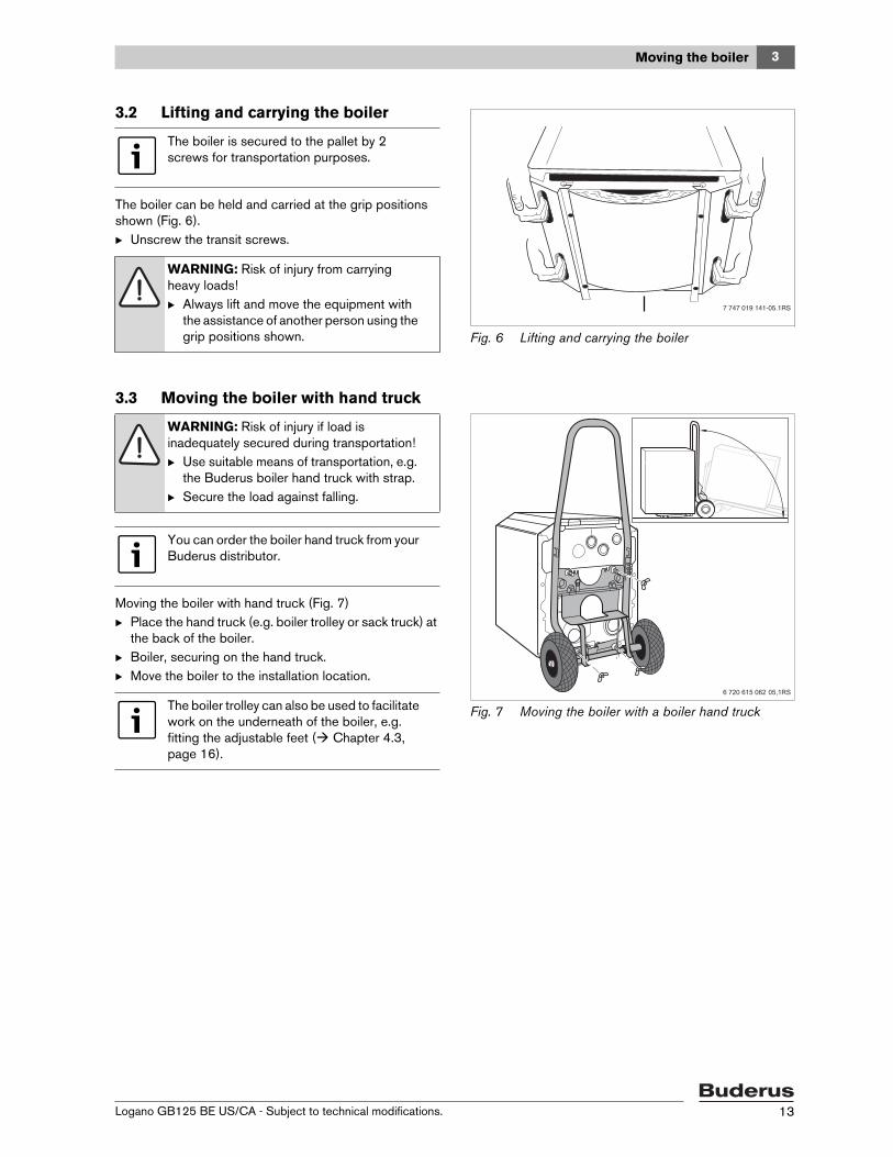
3.2 Lifting and carrying the boiler
The boiler can be held and carried at the grip positions shown (Fig. 6).B Unscrew the transit screws.
Fig. 6 Lifting and carrying the boiler
3.3 Moving the boiler with hand truck
Moving the boiler with hand truck (Fig. 7)B Place the hand truck (e.g. boiler trolley or sack truck) at
the back of the boiler.B Boiler, securing on the hand truck.B Move the boiler to the installation location.
Fig. 7 Moving the boiler with a boiler hand truck
The boiler is secured to the pallet by 2 screws for transportation purposes.
WARNING: Risk of injury from carrying heavy loads!B Always lift and move the equipment with
the assistance of another person using the grip positions shown.
7 747 019 141-05.1RS
WARNING: Risk of injury if load is inadequately secured during transportation!B Use suitable means of transportation, e.g.
the Buderus boiler hand truck with strap.B Secure the load against falling.
You can order the boiler hand truck from your Buderus distributor.
The boiler trolley can also be used to facilitate work on the underneath of the boiler, e.g. fitting the adjustable feet ( Chapter 4.3, page 16).

4 Placing the boiler
Logano GB125 BE US/CA - Subject to technical modifications.14
4 Placing the boilerThis section describes how to install and place the boiler in the boiler room.
4.1 Wall clearancesWherever possible, position the boiler with the recommended wall clearances. Reducing the minimum clearances makes the boiler more difficult to access.
The boiler base or foundation must be perfectly flat and level.
The burner door is factory-installed with the hinges on the right. The burner door can be converted to left-hand closing.
Fig. 8 Wall clearances in the boiler room (boiler positioned on the right-hand side)
CAUTION: Risk of system damage due to freezing!B Install the heating system in a frost-free
room.
Dimen-sion Wall clearance
A Recommended 40"Minimum 27"
B Recommended 27"Minimum 16"
C Recommended 28"Minimum 20"
D Recommended 16"Minimum 6"
L Chapter 2.8, page 8
Tab. 9 Recommended and minimum wall clearances (dimensions in inches).
The boilers are designed for a side clearance of 6".Where applicable, allow extra wall clearances for additional components such as DHW tank pipe connections, flue silencer, other flue components, etc.
WARNING: Risk of fire from flammable materials or liquids! B Clearances less than 6" must comply with
local and statutory codes.B Make sure that there is a sufficient
clearance between combustible materials and the chimney connection as specified by NFPA 31 (distance of 18 ").
B The floor must comply with the requirements of NFPA 31.

4Placing the boiler
Logano GB125 BE US/CA - Subject to technical modifications. 15
4.2 Reversing the burner doorThe burner door is factory-installed with the hinges on the right – the burner door opens to the right. You can change the burner door hinges over to the left-hand side if required to suit the installation site.
Requirement: the burner hood must have been removed first ( Chapter 3.1, page 12).B Removing the burner door ( Chapter 3.1, page 12).B Unscrew the hex bolts [1] and remove the hinge pins
[2].B Fix the hinge pins [2] on the left-hand side of the boiler
using the hex bolts.
Fig. 9 Reversing the burner door (boiler block attachments)
1 Hex bolts2 Hinges
B Unscrew the hex bolts [1] and remove the hinge barrels [2].
B Fix the hinge barrels [2] on the left-hand side of the burner door [3] using the hex bolts.
B Hang the burner door [3] by locating the hinge barrels [2] on the hinge pins [4].
B Check that the heat exchanger baffles are placed horizontally ( Chapter 6.3, page 32).
B Close the burner door [3] and secure with the two hex bolts. Tighten the hex bolts evenly (approx. 90 lbs in) so that the burner door seals properly.
Fig. 10 Reversing the burner door (door attachments)
1 Hex bolts2 Hinge barrels3 Burner door4 Hinges5 Heat exchanger baffle plates
7 747 019 141-08.1RS
1 2 2 1
If the burner door hinges have been changed over to the left-hand side, the burner cable must be disconnected from the burner before opening the burner door.
7 747 019 141-09.1RS
1
4
5
23

4 Placing the boiler
Logano GB125 BE US/CA - Subject to technical modifications.16
4.3 Mounting the adjustable feet (included with B-kit)Level the boiler by turning the adjustable feet to prevent air pockets becoming trapped inside the boiler.
Requirement: the burner hood or burner door panel must have been removed first ( Chapter 3.1, page 12).
B Tilt the boiler with the aid of a hand truck or trolley ( Chapter 3.3, page 13) or place a wooden batten underneath to jack it up.
B Screw in adjustable feet [2] ¼ " – 1/8".B Gently set the boiler down.
Fig. 11 Fitting the adjustable feet(burner not shown)
1 Angle bracket2 Adjustable feet
4.4 Positioning and leveling the boilerB Position the boiler in its final location.B Level the boiler by rotating the adjustable feet as
required and using a level.
Fig. 12 Leveling the boiler
If the boiler is mounted on top of a horizontal hot water tank the adjustable feet are not used.
7 747 019 141-10.1RS
12
Protect boiler connections from damage and dirt if the boiler is not to be installed immediately.
7 747 019 141-11.1RS

5Installing the boiler
Logano GB125 BE US/CA - Subject to technical modifications. 17
5 Installing the boilerThis section details how to install your boiler correctly. This involves the following steps:• Flue pipe installation• Providing air supply for combustion• Making the water connections• Making the electrical connections• Connecting the fuel supply
5.1 Flue pipe installationThe overall burner air supply/boiler flue pipe system conforms to the types of oil combustion equipment listed in the table below.
Observe the national standards and regulations for operating oil-fired appliances.
DANGER: Risk of fatal injury from toxic flue gases!B Never connect more than one boiler to a
flue system – regardless of whether the flue is vertical or horizontal.
B Common venting systems can cause damage to property and personal injury.
B Do not route the flue system through another flue system that is in use, e.g. a masonry chimney connected to a wood stove.
B Follow the instructions of the flue pipe manufacturer.
The boiler must be installed by a trained and certified installer in accordance with all requirements of NFPA-31, "Installation of Oil-Burning Equipment". Installation must comply with all local and national codes applicable to the installation of oil-fired boilers.
In Canada, the requirements of CSA/CGA-B139 Installation Code apply.
The GB125 boiler is approved for zero (0") clearance between its concentric vent pipe and combustibles.
Because of the tight construction of modern houses, this boiler must draw all air supply for combustion from outside (RLU).
Installa-tion type Combustion air supply and flue system
I or
HT-K
Concentric supply air and flue pipe exiting through external wall. Combustion air supply and flue systems are part of the combustion
equipment.II or
DO
Concentric supply air and flue gas routing via roof. Combustion air supply and flue sys-tems are part of the combustion equipment.
III or
GA-K
Concentric air/flue gas routing through a flue inside a duct. The space around the vent
pipe is used for combustion air.
Tab. 10 Types of installation

5 Installing the boiler
Logano GB125 BE US/CA - Subject to technical modifications.18
5.2 Test portsFlue gas readings and combustion air temperature readings are taken exclusively at the dedicated testing ports.
Follow the directions in the instructions for the Logatop BE oil burner.
Fig. 13 Installing the flue/air connector (included with the venting system)
1 Air intake test port2 Flue gas test port

5Installing the boiler
Logano GB125 BE US/CA - Subject to technical modifications. 19
Choice of installation site for side-wall flue terminationChoosing the right location for the terminal is critical to proper functioning of the appliance. As well as the minimum clearances ( Fig. 14), the following rules must be observed:
Fig. 14 Minimum clearances for side wall terminations
1. The termination should not face the prevailing wind direction.
2. The termination must be installed in such a way that the flue gases can disperse freely without re-entering the building.
3. The termination must be at least 2 ft from adjacent buildings and it must not be possible for the flue gas to enter adjacent buildings.
4. Where the building adjoins public walkways, the termination must be located at least 7 ft above ground. Make sure that freezing condensate does not constitute a hazard.
5. The termination must never be located below building overhangs, roof eaves, porches, enclosed spaces or lower parts of the building that could prevent unrestricted outflow of the flue gases.
6. The termination must never be located within 3 ft of inside corners of buildings and never less than 2 ft from outside corners of buildings.
7. If there is a fan-assisted air intake vent within 10 ft, the termination must be at least 3 ft above it.
8. The termination must be at least 4 ft below, 1 ft above or 4 ft horizontally from doors, windows or air inlet vents.
9. The termination must be at least 1 ft above ground and snow line, and protected from falling and accumulating snow, ice, leaves or debris.
10. The termination should be at least 3 ft from any type of building opening, oil tank filling or venting apparatus, and 6 ft from gas meters and similar equipment.
11. The position of the termination should be chosen so that the last horizontal section of pipe slopes downwards to the inside by ¼ " per ft. The flue terminal itself must also be inclined at ¼ " per ft to the inside so that any condensate drains inwards.
Concentricwall terminations on the house wall
at least 1 ft above grade and snow line
Concentric wall terminations on the house wall
Concentricwall terminations on the house wall
6 720 641 158-20.1TL
.
.
Forced Air InletGravity Air Inlet
must be at least 3 ft above forced air inlets within 10 ft.
5 Installing the boiler
Logano GB125 BE US/CA - Subject to technical modifications.20
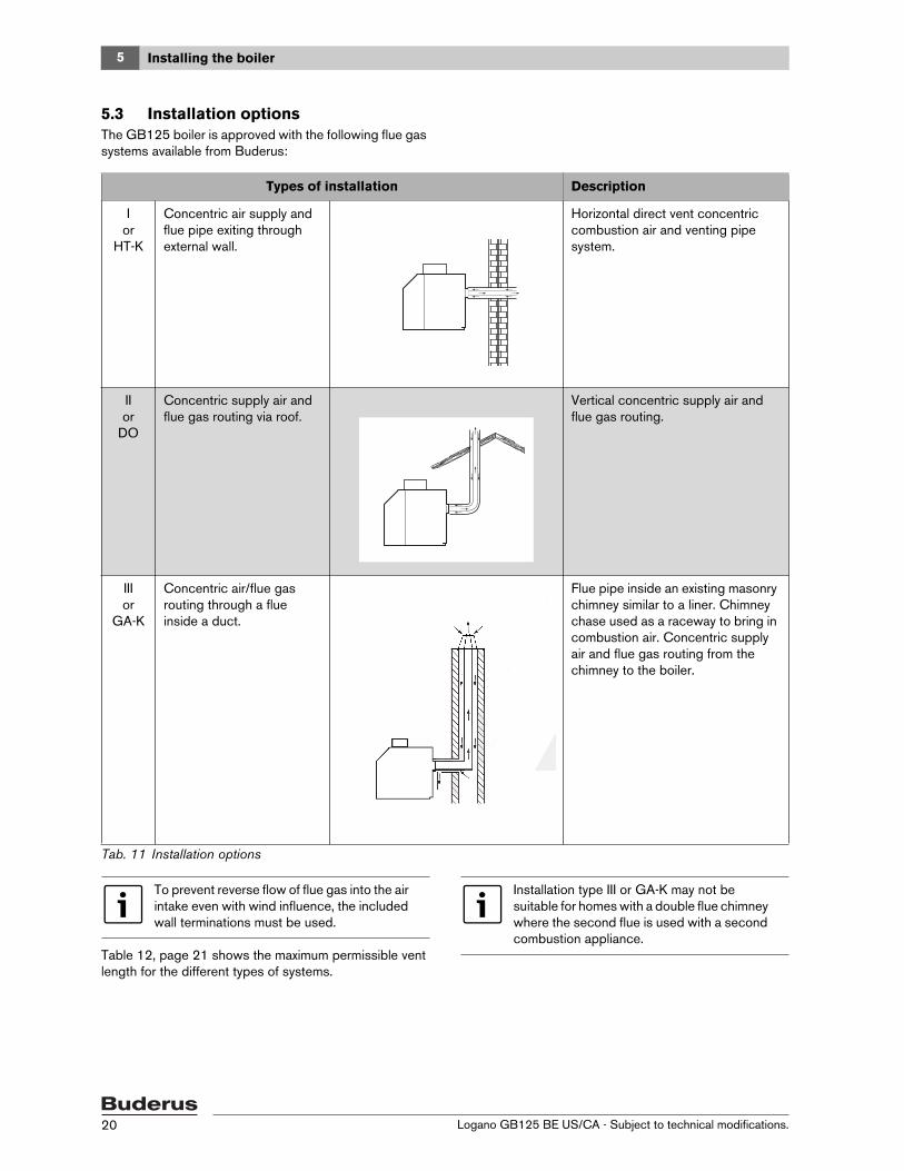
5.3 Installation optionsThe GB125 boiler is approved with the following flue gas systems available from Buderus:
Table 12, page 21 shows the maximum permissible vent length for the different types of systems.
Types of installation Description
I or
HT-K
Concentric air supply and flue pipe exiting through external wall.
Horizontal direct vent concentric combustion air and venting pipe system.
II or
DO
Concentric supply air and flue gas routing via roof.
Vertical concentric supply air and flue gas routing.
III or
GA-K
Concentric air/flue gas routing through a flue inside a duct.
Flue pipe inside an existing masonry chimney similar to a liner. Chimney chase used as a raceway to bring in combustion air. Concentric supply air and flue gas routing from the chimney to the boiler.
Tab. 11 Installation options
To prevent reverse flow of flue gas into the air intake even with wind influence, the included wall terminations must be used.
Installation type III or GA-K may not be suitable for homes with a double flue chimney where the second flue is used with a second combustion appliance.

5Installing the boiler
Logano GB125 BE US/CA - Subject to technical modifications. 21
Pipe changes of directionThe overall lengths apply for systems with one elbow. Every additional elbow (accessory) reduces the maximum vent length by 3 ft (1 m).
Maximum length of flue pipe, feet (m)
Plastic flue system DN 80/125
Boiler capacity I or HT-KConcentric air sup-
ply and flue pipe exit-ing through external
wall
II or DOConcentric supply
air and flue gas rout-ing via roof
III or GA-KConcentric air/flue gas routing through a flue inside a duct
GB125 22 17’ (5.2 m) 51’ (17 m) 51’ (17 m)
30 17’ (5.2 m) 64’ (21 m) 64’ (21 m)
35 17’ (5.2 m) 71’ (23 m) 71’ (23 m)
Tab. 12 Maximum flue pipe lengths
For installation details see the Installation Instructions for the different flue gas systems.

5 Installing the boiler
Logano GB125 BE US/CA - Subject to technical modifications.22
5.4 Making the water connections
5.4.1 Installing B-kitThe safety valve and pressure/temperature gauge are installed into the supply manifold as described below:B Use the 1-1/4" BSP x NPT conversion nipple and
install the unmarked end into the supply (VK) connection of the boiler. This side also has longer thread length and the thread is straight (BSP).
B The conversion nipple is marked on the 1-1/4" NPT side with pink color and a NPT stamping in the pipe.
Fig. 15 Sealing the converter
B Seal 90° 1-1/4 NPT elbow on double nipple.B Mount conversion nipple on the elbow and align as
desired (Fig. 16).B Seal 90° elbow, safety valve and pressure/temperature
gauge.
Fig. 16 B-kit Installation
1 90° 1-¼" NPT elbow2 Double nipple3 Supply manifold4 Pressure/temperature gauge5 Safety valve6 90° ¾" NPT street elbow
CAUTION: Risk of system damage due to leaking connections!B Install hydraulic connections free of
tension on the boiler.
The safety valve can only be installed after the hydrostatic test (Chapter 5.5, page 24) has been completed. Use the supplied ¾" 90° elbow to ensure that the safety valve is installed horizontally.
We recommend installing a dirt filter (optional) in the boiler return connection to reduce build-up of debris on the water side.
5Installing the boiler
Logano GB125 BE US/CA - Subject to technical modifications. 23
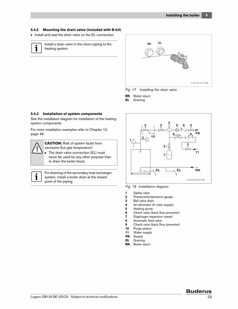
5.4.2 Mounting the drain valve (included with B-kit)B Install and seal the drain valve on the EL connection.
Fig. 17 Installing the drain valve
RK Boiler returnEL Draining
5.4.3 Installation of system componentsSee the installation diagram for installation of the heating system components.
For more installation examples refer to Chapter 10, page 49.
Fig. 18 Installation diagram
1 Safety valve2 Pressure/temperature gauge3 Ball valve drain4 Air eliminator (in main supply)5 Heating pump6 Check valve (back flow preventer)7 Diaphragm expansion vessel8 Automatic feed valve9 Check valve (back flow preventer)10 Purge station11 Water supplyVK SupplyEL DrainingRK Boiler return
Install a drain valve in the return piping to the heating system.
7 747 019 141-15.1RS
RK EL
CAUTION: Risk of system faults from excessive flue gas temperature!B The drain valve connection (EL) must
never be used for any other purpose than to drain the boiler block.
For draining of the secondary heat exchanger system, install a boiler drain at the lowest point of the piping.
5 Installing the boiler
Logano GB125 BE US/CA - Subject to technical modifications.24
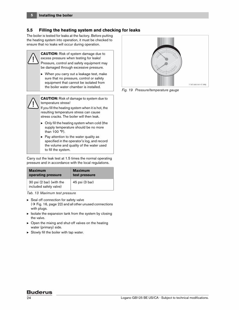
5.5 Filling the heating system and checking for leaksThe boiler is tested for leaks at the factory. Before putting the heating system into operation, it must be checked to ensure that no leaks will occur during operation.
Carry out the leak test at 1.5 times the normal operating pressure and in accordance with the local regulations.
B Seal off connection for safety valve ( Fig. 16, page 22) and all other unused connections with plugs.
B Isolate the expansion tank from the system by closing the valve.
B Open the mixing and shut-off valves on the heating water (primary) side.
B Slowly fill the boiler with tap water.
Fig. 19 Pressure/temperature gauge
CAUTION: Risk of system damage due to excess pressure when testing for leaks! Pressure, control and safety equipment may be damaged through excessive pressure.
B When you carry out a leakage test, make sure that no pressure, control or safety equipment that cannot be isolated from the boiler water chamber is installed.
CAUTION: Risk of damage to system due to temperature stress!If you fill the heating system when it is hot, the resulting temperature stress can cause stress cracks. The boiler will then leak.
B Only fill the heating system when cold (the supply temperature should be no more than 100 °F).
B Pay attention to the water quality as specified in the operator's log, and record the volume and quality of the water used to fill the system.
Maximumoperating pressure
Maximum test pressure
30 psi (2 bar) (with the included safety valve)
45 psi (3 bar)
Tab. 13 Maximum test pressure
7 747 019 141-17.1RS

5Installing the boiler
Logano GB125 BE US/CA - Subject to technical modifications. 25
B Bleed heat exchanger using the purge valve [1].B Slowly fill the heating system. Observe the pressure
gauge while filling.B Check the connections and piping to make sure they
are watertight.B Bleed the system via the radiator purge valves (if
applicable).B Top up with water if the pressure drops as a result of
bleeding the system.B Installing the safety valve ( Fig. 16, page 22).B When no leaks are found, remove pressure and
uninstall the plugs. Install safety valve and open valve to expansion vessel.
Fig. 20 Bleeding the heat exchanger system
1 Purge valve on the heat exchanger system
5.6 Connecting the fuel supplyB Install the oil line per local code.
The furnished Tigerloop oil filter must be installed on the outside of the boiler using the supplied mounting bracket.B Inspect the existing oil line and replace if necessary.
Check swing direction on burner door and reverse door swing if desired.
B Use the mounting bracket [7] as a drill template and drill 4 holes in the jacket panel.
B Secure the mounting bracket [7] to boiler side panel.B For a 3/8" oil line, install a 3/8" flare x 3/8" NPT adapter
[1] in the inlet and a 1/4" x 3/8" NPT adapter [2] between the oil filter [4] (Tigerloop) and the Firomatic valve [3].
B Install and seal the FiroMatic valve on the oil filter (Tigerloop) [4].
B Install the vacuum gauge in its adapter [6] and screw into the oil line feeding the burner.
B Connect the return oil line from the burner using the G 3/8" x 1/4" NPT adapter [5] back to the oil filter.
B Secure oil filter assembly to the mounting bracket.B Attach oil lines.B Check entire oil line assembly for leaks.
Fig. 21 Oil filter (Tigerloop)
1 Flare-NPT adapter (3/8" NPT)2 1/4" x 3/8" NPT adapter3 FiroMatic valve4 Oil filter (Tigerloop)5 NPT adapter (G 3/8" (60) x 1/4" NPT)6 Vacuum gauge7 Mounting bracket
5.7 Bleed off condensate
WARNING: Health risk from contaminated domestic water!B Always observe the regulations and
standards applicable in your jurisdiction for the prevention of contamination of drinking water (e.g. by water from heating systems).
Ensure that the siphon and piping are installed that fluids drain away freely, and backup into the boiler is prevented.
5 Installing the boiler
Logano GB125 BE US/CA - Subject to technical modifications.26
The boiler has the potential to produce significant amounts of condensate which must be drained and disposed of properly.
Follow all applicable codes and regulations covering the disposal of condensate originating from combustion appliances.• Ensure that untreated condensate is only passing
through hoses and piping suitable for very low pH levels.
• If the building is connected to a municipal sewage system, observe the rules and regulations for disposal into the system.
• If the building is connected to a septic system, a neutralizer is recommended to avoid damage to the system.
• Ensure the siphon is always filled with fluid to avoid unpleasant odors.
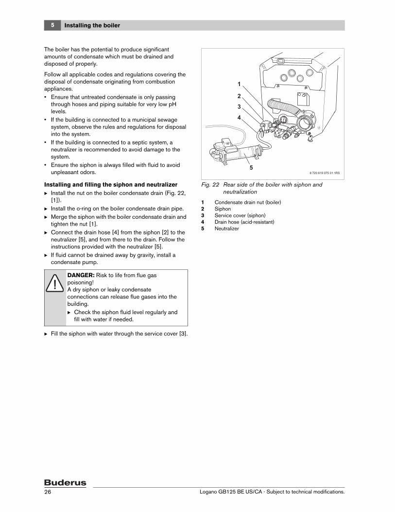
Installing and filling the siphon and neutralizerB Install the nut on the boiler condensate drain (Fig. 22,
[1]).B Install the o-ring on the boiler condensate drain pipe.B Merge the siphon with the boiler condensate drain and
tighten the nut [1].B Connect the drain hose [4] from the siphon [2] to the
neutralizer [5], and from there to the drain. Follow the instructions provided with the neutralizer [5].
B If fluid cannot be drained away by gravity, install a condensate pump.
B Fill the siphon with water through the service cover [3].
Fig. 22 Rear side of the boiler with siphon and neutralization
1 Condensate drain nut (boiler)2 Siphon3 Service cover (siphon)4 Drain hose (acid-resistant)5 Neutralizer
DANGER: Risk to life from flue gas poisoning!A dry siphon or leaky condensate connections can release flue gases into the building.B Check the siphon fluid level regularly and
fill with water if needed.
5Installing the boiler
Logano GB125 BE US/CA - Subject to technical modifications. 27
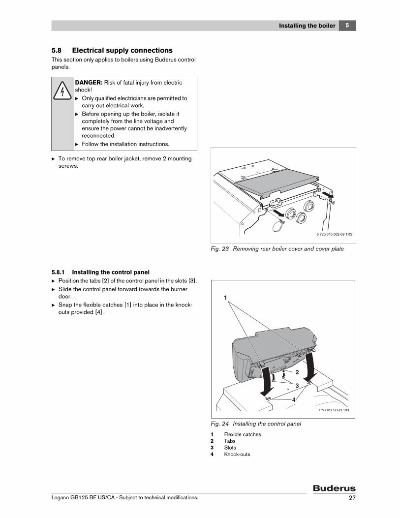
5.8 Electrical supply connectionsThis section only applies to boilers using Buderus control panels.
B To remove top rear boiler jacket, remove 2 mounting screws.
Fig. 23 Removing rear boiler cover and cover plate
5.8.1 Installing the control panelB Position the tabs [2] of the control panel in the slots [3].B Slide the control panel forward towards the burner
door.B Snap the flexible catches [1] into place in the knock-
outs provided [4].
Fig. 24 Installing the control panel
1 Flexible catches2 Tabs3 Slots4 Knock-outs
DANGER: Risk of fatal injury from electric shock!B Only qualified electricians are permitted to
carry out electrical work.B Before opening up the boiler, isolate it
completely from the line voltage and ensure the power cannot be inadvertently reconnected.
B Follow the installation instructions.
1
2
3
4
7 747 019 141-21.1RS

5 Installing the boiler
Logano GB125 BE US/CA - Subject to technical modifications.28
B Remove the top cover of the control panel. – Unscrew the cover screws [1].
B Secure the control panel with self-tapping screws [2].
Fig. 25 Removing the cover
1 Cover screws2 Self-tapping screws
5.8.2 Installing the temperature sensor assembly
B Feed the capillary tubes and the sensor lead [2] through the cable entry in the front boiler top panel [1] to the sensor well [3].
B Roll up surplus capillary tube and sensor lead length and place on top of the thermal insulation.
B Feed the burner cable [4] through the cable entry in the front boiler top panel [1] to the control panel.
B Connect the burner cable [4] to the control panel as indicated by the terminal markings.
Fig. 26 Routing and connecting cables
1 Cable entry in the front boiler cover2 Capillary tube and sensor cable3 Sensor well4 Burner cable
1
27 747 019 141-22.1RS
CAUTION: Risk of damage to system!Capillary tubes can get damaged from severe kinking or sharp burrs.
B Route capillary tubes carefully, avoiding bending them excessively

5Installing the boiler
Logano GB125 BE US/CA - Subject to technical modifications. 29
B Insert the temperature sensor assembly and balancing spring [3] in the sensor well [1] and push fully home. The plastic coil [2] is pushed back automatically.
B Push the sensor retaining clip [4] (supplied with the control panel) sideways onto the top of the well.
Fig. 27 Installing the temperature sensor assembly
1 Sensor well (measurement point)2 Plastic coil3 Balancing spring4 Sensor retaining clip
5.8.3 Power connection and connections of additional components
Establish a permanent connection to the main power connection in accordance with the locally applicable regulations.
B Route all cables through the cable entries above the thermal insulation to the control panel and connect in accordance with the wiring diagram ( Chapter 12, page 60).
B Remove blind connector from "Abgasüberwachung" Fig. 28.
B Insert flue gas manual reset high limit (STB) connectors in socket labeled "Abgasüberwachung" as shown in Fig. 29.
B Connect green burner plug in the socket labeled "Brenner".
Fig. 28 Routing the manual reset high limit and burner cables above the insulation to the control panel
Fig. 29 Connecting the manual reset high limit (STB) to the control panel
Ensure good contact between the sensor surfaces in the well [1] to ensure reliable heat conduction. Use the balancing spring [3].
1
1
4
2
3
7 747 019 141-24.1RS
WARNING: Fire hazard from hot boiler components!Hot boiler components may damage electrical cables
B Make sure that all cables are routed through the conduits provided or on the outside of the boiler's thermal insulation.
B Make sure the boiler is electrically grounded to NEC or CEC requirements.
The manual reset high limit (STB) arrives tripped and must be reset before commissioning.

5 Installing the boiler
Logano GB125 BE US/CA - Subject to technical modifications.30
5.8.4 Installing cable strain reliefSecure all cable runs with cable clips (included with the control panel):B Insert the cable clips together with the cable from the
top into the slots in the frame (step 1).B Slide the cable clips downward (step 2).B Push against the clips (step 3).B Flip the lever up (step 4).
Fig. 30 Securing cables with cable clips
5.9 Installing the back boiler coverB Place the control panel cover [1] in position and secure
with screws.B Install the rear boiler top panel [2].
Fig. 31 Installing the rear boiler cover
1 Control panel cover2 Rear boiler cover
7 747 019 141-25.1RS

6Starting up the heating system
Logano GB125 BE US/CA - Subject to technical modifications. 31
6 Starting up the heating systemThis section describes the initial start-up procedure regardless of the installed control panel.
B Complete the commissioning report during this process ( Chapter 6.9, page 35).
Additional information on boiler room conditions and requirements, combustion air supply and flue systems and boiler operation can be found in Chapter 2.9, page 9.
6.1 Bringing the system up to operating pressureBring the system up to the normal operating pressure before commissioning.
B Top up the heating water or drain via the boiler fill and drain valve until the required operating pressure has been reached: minimum 15 psi, maximum 30 psi positive pressure (depending on safety valve installed).
B Bleed the heating system while filling.
Fig. 32 Pressure/temperature gauge for showing operating pressure and supply temperature
WARNING: Risk of boiler damage from excessive dust and air contamination!B Do not operate the boiler when there is
potential for a lot of dust being drawn into the combustion air supply.
B Install an air filter if the supply of combustion air contains large quantities of dust (e.g. from unpaved roads and tracks or dusty workplaces such as quarries, mines, etc.) or airborne particles.
CAUTION: Risk of damage to system due to material stress caused by temperature differentials!B Only fill the heating system when cold (the
flow temperature should be no more than 100 °F).
WARNING: Health risk from contaminated domestic water!B Observe all national standards and
regulations regarding prevention of domestic water contamination (e.g. by water from heating systems).
7 747 019 141-17.1RS
6 Starting up the heating system
Logano GB125 BE US/CA - Subject to technical modifications.32
6.2 Testing safety valveB Make sure that no people are in the discharge area of
the safety valve.B Raise the lever on the safety valve.
The safety valve must open and release pressure. If the safety valve fails to release excess pressure, it must be replaced, because otherwise system components may be damaged by excessive operating pressure.
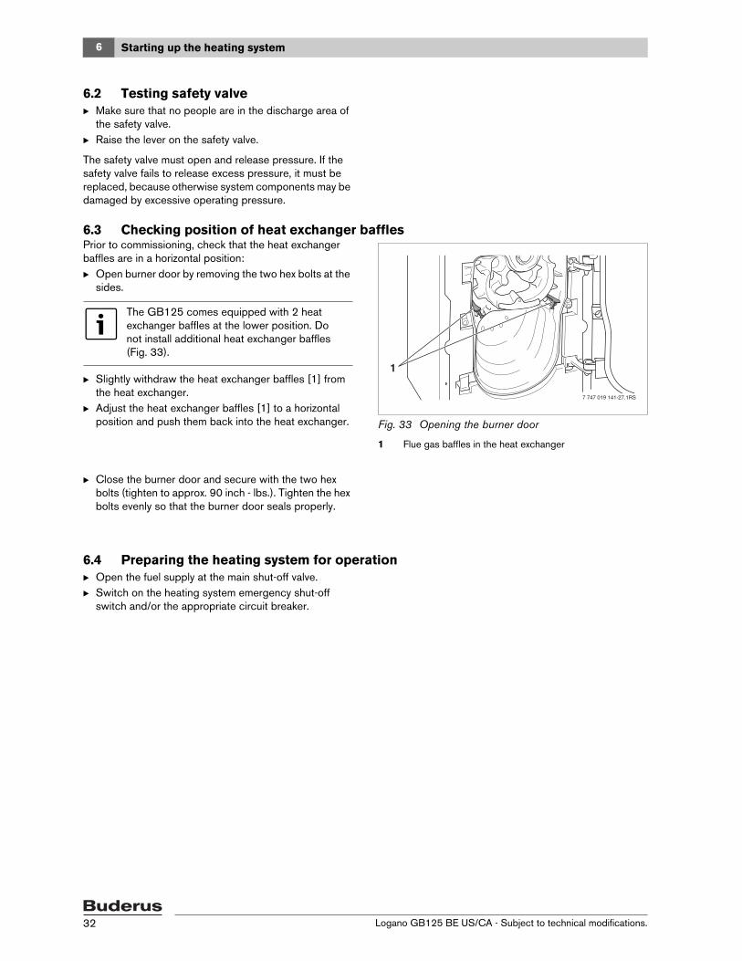
6.3 Checking position of heat exchanger bafflesPrior to commissioning, check that the heat exchanger baffles are in a horizontal position:B Open burner door by removing the two hex bolts at the
sides.
B Slightly withdraw the heat exchanger baffles [1] from the heat exchanger.
B Adjust the heat exchanger baffles [1] to a horizontal position and push them back into the heat exchanger. Fig. 33 Opening the burner door
1 Flue gas baffles in the heat exchanger
B Close the burner door and secure with the two hex bolts (tighten to approx. 90 inch - lbs.). Tighten the hex bolts evenly so that the burner door seals properly.
6.4 Preparing the heating system for operationB Open the fuel supply at the main shut-off valve.B Switch on the heating system emergency shut-off
switch and/or the appropriate circuit breaker.
The GB125 comes equipped with 2 heat exchanger baffles at the lower position. Do not install additional heat exchanger baffles (Fig. 33).
1
7 747 019 141-27.1RS

6Starting up the heating system
Logano GB125 BE US/CA - Subject to technical modifications. 33
6.5 Starting up the control panel and the burnerFor further start-up steps, follow the burner start-up sequence. Refer to the burner documentation for details.
Turn the control panel power switch to the "ON" position [2]. The burner starts up if the system is calling for heat or if you set the control panel to manual mode ( Control panel servicing instructions).B Select "Manual" mode .B Set the boiler-water temperature control [1] to the
desired temperature. Fig. 34 Switching on the control panel
1 Boiler aquastat2 On-off switch
6.6 Taking measurementsAllow burner to operate for 15 to 20 minutes before performing a combustion test. Earlier combustion tests can lead to incorrect readings as a result of burning off the sealant rope. We recommend rechecking the burner after a few weeks of operation.
Required instruments:• CO2 measuring equipment• Meter to measure draught• Oil pressure gauge 0-350 psi (25 bar)• Flue gas temperature sensor• Smoke tester
B Check the combustion chamber pressure at the pressure test port [1].
B Check draught via the test port on the combustion air intake/flue gas connections ( Fig. 13, page 18).
B Make all additional measurements according to the burner documentation.
Fig. 35 Pressure test port on burner door
1 Pressure test port
The manual reset high limit (STB) comes tripped and must be reset prior to start-up. To reset, unscrew cap on the side of the housing and depress green button. Replace cap.
AUT
190 160 140120
AUT
190 160 140120
1
2
6720641158.1TL
Incorrect burner adjustment can cause contamination of the boiler (e.g. soot). Faults may occur more often than normal.B Always check combustion with the
following instruments. B Never adjust burner visually.
1
7 747 019 141-29.1RS

6 Starting up the heating system
Logano GB125 BE US/CA - Subject to technical modifications.34
6.7 Checking the manual reset high limit (STB)The manual reset high limit interrupts the power supply if the maximum permissible flow temperature is exceeded.To enable a boiler reset and re-starting, the fault must be removed and the system must have fallen back below the limit.B Check the function of the manual reset high limit
( service instructions for the control panel).
6.8 Installing the burner hoodB Position the burner hood on the hooks on the boiler
outer casing.B Secure the burner hood with the two screws at the
sides.
Fig. 36 Installing the burner hood
DANGER: Risk of fatal injury from electric shock!B Only operate the boiler with the burner
hood installed.
6Starting up the heating system
Logano GB125 BE US/CA - Subject to technical modifications. 35
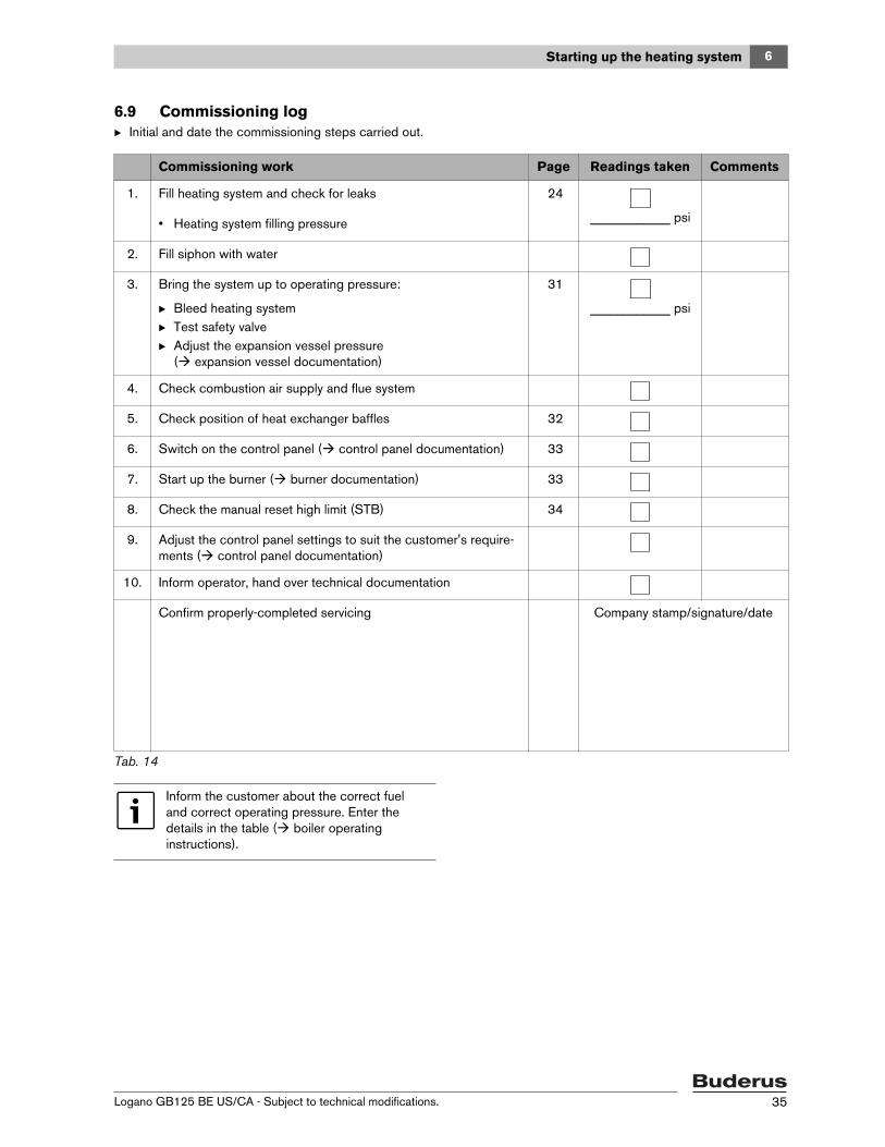
6.9 Commissioning logB Initial and date the commissioning steps carried out.
Commissioning work Page Readings taken Comments
1. Fill heating system and check for leaks 24
____________ psi• Heating system filling pressure
2. Fill siphon with water
3. Bring the system up to operating pressure:
B Bleed heating systemB Test safety valveB Adjust the expansion vessel pressure
( expansion vessel documentation)
31
____________ psi
4. Check combustion air supply and flue system
5. Check position of heat exchanger baffles 32
6. Switch on the control panel ( control panel documentation) 33
7. Start up the burner ( burner documentation) 33
8. Check the manual reset high limit (STB) 34
9. Adjust the control panel settings to suit the customer's require-ments ( control panel documentation)
10. Inform operator, hand over technical documentation
Confirm properly-completed servicing Company stamp/signature/date
Tab. 14
Inform the customer about the correct fuel and correct operating pressure. Enter the details in the table ( boiler operating instructions).

7 Shutting down the heating system
Logano GB125 BE US/CA - Subject to technical modifications.36
7 Shutting down the heating system
7.1 Normal shut-downB With Buderus control panel: switch off the on/off
switch [1] on the control panel (position "0”). This switches off the boiler and all its components (e.g. burner).
Fig. 37 Switching off the heating system (Logamatic)
1 On-off switch
B Shut off fuel supply by closing main valve.
7.2 Shutting down the heating system in an emergency
7.2.1 Action in an emergencyExplain to the customer what to do in an emergency, e.g. a fire.
B Never put yourself at risk of fatal injury. Your own safety must always take the highest priority.
B Turn off the main isolating fuel valve.B Disconnect the heating system from the electrical
power supply by means of the emergency shut-off switch or the appropriate circuit breaker.
Fig. 38 Heating system emergency shut-off switch
CAUTION: Risk of system damage due to freezing!If the heating system has been switched off, it may freeze in cold weather conditions.
B Leave the heating system switched on as long as possible.
B Protect your system from freezing by draining the boiler, the heating system and hot water pipes at the lowest point.
AUT
190 160 140120
1
6720641158-34.1TL
Use the heating system emergency shut-off switch located outside the boiler room or the heating system circuit breaker for emergency shutdown.

8Heating system inspection
Logano GB125 BE US/CA - Subject to technical modifications. 37
8 Heating system inspection
8.1 Why is regular maintenance important?Heating systems should be regularly maintained for the following reasons:
• to achieve a high level of efficiency and to operate the system economically (low fuel consumption),
• to achieve a high level of operational reliability,• to maintain the cleanest possible combustion,• to ensure reliable operation and a long service life.
Maintenance may only be carried out by a qualified service technician. If parts are replaced, only Buderus approved components may be used. Maintenance must be carried out once a year. The results of the inspection must be recorded in the inspection and maintenance log.
8.2 Preparing the boiler for inspection
B Shut down the heating system. ( Chapter 7.1, page 36)
B Remove burner hood from boiler. ( Chapter 3.1, page 12).
B Disconnect electrical power to burner.
Spare parts can be purchased from your Buderus distributor using the parts list (Chapter 11, "Spare parts," page 52).
DANGER: Risk of fatal injury from electric shock!B Before opening up the boiler,
isolate it completely from the mains power supply and ensure the power cannot be inadvertently reconnected.

8 Heating system inspection
Logano GB125 BE US/CA - Subject to technical modifications.38
8.3 Cleaning the boilerThe boiler can be cleaned with brushes and/or by a wet method. Cleaning equipment is available from your Buderus wholesaler.
B Open burner door by removing the two hex bolts on the sides.
8.3.1 Cleaning the boiler with cleaning brushesB Note the position of the heat exchanger baffles [1] for
later.B Remove the heat exchanger baffles [1] from the heat
exchanger.B Clean the heat exchanger baffles [1] with one of the
two cleaning brushes.
Fig. 39 Opening the burner door
1 Flue gas baffles in the heat exchanger
B Clean the hot gas passages by turning the round cleaning brush.
Fig. 40 Brushing out the hot gas flues
DANGER: Risk of fatal injury from escaping flue gases!B Follow these instructions carefully to
ensure safe operation of the system after completing the cleaning.
WARNING: Risk of burns from touching hot boiler parts!B Wear appropriate protective gloves or use
pliers.
1
7 747 019 141-27.1RS
7 747 019 141-37.1RS
8Heating system inspection
Logano GB125 BE US/CA - Subject to technical modifications. 39
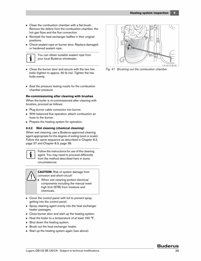
B Clean the combustion chamber with a flat brush. Remove the debris from the combustion chamber, the hot gas flues and the flue connection.
B Reinstall the heat exchanger baffles in their original positions.
B Check sealant rope on burner door. Replace damaged or hardened sealant rope.
B Close the burner door and secure with the two hex bolts (tighten to approx. 90 lb ins). Tighten the hex bolts evenly.
Fig. 41 Brushing out the combustion chamber
B Seal the pressure testing nozzle for the combustion chamber pressure.
Re-commissioning after cleaning with brushesWhen the boiler is re-commissioned after cleaning with brushes, proceed as follows:
B Plug burner cable connector into burner.B With balanced flue operation, attach combustion air
hose to the burner.B Prepare the heating system for operation.
8.3.2 Wet cleaning (chemical cleaning)When wet cleaning, use a Buderus-approved cleaning agent appropriate for the degree of soiling (soot or scale). Follow the same sequence as described in Chapter 8.2, page 37 and Chapter 8.3, page 38.
B Cover the control panel with foil to prevent spray getting into the control panel.
B Spray cleaning agent evenly into the heat exchanger heater passages.
B Close burner door and start up the heating system.B Heat the boiler to a temperature of at least 160 °F.B Shut down the heating system.B Brush out the heat exchanger heater.B Start up the heating system again (see above).
You can obtain suitable sealant rope from your local Buderus wholesaler.
7 747 019 141-38.1RS
Follow the instructions for use of the cleaning agent. You may need to proceed differently from the method described here in some circumstances.
CAUTION: Risk of system damage from corrosion and short-circuit!B When wet cleaning protect electrical
components including the manual reset high limit (STB) from moisture and chemicals.
8 Heating system inspection
Logano GB125 BE US/CA - Subject to technical modifications.40
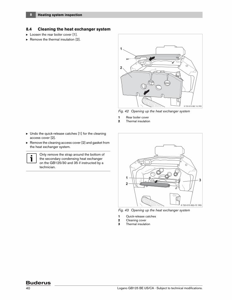
8.4 Cleaning the heat exchanger systemB Loosen the rear boiler cover [1].B Remove the thermal insulation [2].
Fig. 42 Opening up the heat exchanger system
1 Rear boiler cover2 Thermal insulation
B Undo the quick-release catches [1] for the cleaning access cover [2].
B Remove the cleaning access cover [2] and gasket from the heat exchanger system.
Fig. 43 Opening up the heat exchanger system
1 Quick-release catches2 Cleaning cover3 Thermal insulation
Only remove the strap around the bottom of the secondary condensing heat exchanger on the GB125/30 and 35 if instructed by a technician.

8Heating system inspection
Logano GB125 BE US/CA - Subject to technical modifications. 41
B Clean the inside of the heat exchanger system with plastic cleaning brush [1] (brush available separately).
B Vacuum out visible and loose combustion residue under the cleaning access cover.
B Check the gasket of the cleaning access cover and replace if damaged or hardened.
Fig. 44 Brushing out the heat exchanger system (viewed from above)
1 Plastic cleaning brush (accessory, part # 7747007899)
Wet cleaning can also be carried out in addition. Follow the same procedure as described for cleaning with the brush.
CAUTION: Risk of system damage due to use of incorrect brushes!B Use only the cleaning brushes suitable for
the heat exchanger system.
Avoid damaging the flue gas temperature sensor.
DANGER: Risk of fatal injury from escaping flue gases!B When reinstalling the cleaning access
cover, take care to ensure it is seated correctly and seals properly!
CAUTION: Risk of system damage from chemical cleaning agents!B When wet cleaning the heat exchanger,
use only water or cleaning agents approved by Buderus.
B Reinstall cleaning access cover and gasket.
B After completing cleaning, check any connections that were disconnected for leaks.
Follow the instructions for use of the cleaning agent. Under some circumstances you may have to proceed differently from the method described here.
CAUTION: Risk of system damage from corrosion and short-circuit!B When wet cleaning protect electrical
components including the manual reset high limit (STB) from moisture and chemicals.

8 Heating system inspection
Logano GB125 BE US/CA - Subject to technical modifications.42
Cleaning the condensate collector
B Open the condensate collector cleanout cover [1].B Remove condensate residues.B Securely replace the condensate collector cleanout
cover [1].
Fig. 45 Cleaning the condensate collector
1 Cleaning cover
8.5 Cleaning the neutralization and siphonThe procedure for cleaning the neutralizer unit is described in a separate instruction manual.
B Disconnect the condensate pipes from the siphon.B Remove deposits in the siphon and refill with water.B Reinstall the condensate pipes.
WARNING: Risk of injury from acid burning!The condensate in the condensate collector and the siphon can reach a pH level of 2.
B Always wear suitable clothing and protective goggles when cleaning.
DANGER: Risk to life from flue gas poisoning!A dry siphon or leaky condensate connections can release flue gases into the building.
B Check the siphon fluid level regularly and fill with water if needed.
8Heating system inspection
Logano GB125 BE US/CA - Subject to technical modifications. 43
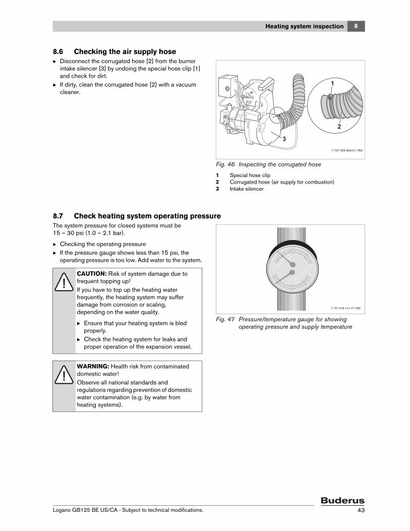
8.6 Checking the air supply hose B Disconnect the corrugated hose [2] from the burner
intake silencer [3] by undoing the special hose clip [1] and check for dirt.
B If dirty, clean the corrugated hose [2] with a vacuum cleaner.
Fig. 46 Inspecting the corrugated hose
1 Special hose clip2 Corrugated hose (air supply for combustion)3 Intake silencer
8.7 Check heating system operating pressureThe system pressure for closed systems must be 15 – 30 psi (1.0 – 2.1 bar).
B Checking the operating pressure B If the pressure gauge shows less than 15 psi, the
operating pressure is too low. Add water to the system.
Fig. 47 Pressure/temperature gauge for showing operating pressure and supply temperature
CAUTION: Risk of system damage due to frequent topping up!If you have to top up the heating water frequently, the heating system may suffer damage from corrosion or scaling, depending on the water quality.
B Ensure that your heating system is bled properly.
B Check the heating system for leaks and proper operation of the expansion vessel.
WARNING: Health risk from contaminated domestic water!Observe all national standards and regulations regarding prevention of domestic water contamination (e.g. by water from heating systems).
7 747 019 141-17.1RS

8 Heating system inspection
Logano GB125 BE US/CA - Subject to technical modifications.44
B Add water through the fill valve.B Bleed the heating system.B Check the operating pressure again.
8.8 Test safety valveThe functioning of the safety valve must be checked at regular intervals (every 1 – 3 years depending on local regulations).
B Make sure that no persons are in the discharge area of the safety valve.
B Raise the lever on the safety valve.
The safety valve must open and release pressure. If the safety valve fails to release excess pressure, it must be replaced, because otherwise system components may be damaged by excessive operating pressure.
8.9 Concentric supply air and flue gas routing
B Check combustion air supply and flue gas routing for dirt and leaks. Measure CO/CO2 levels in boiler flue socket using annular gap method.
B Check that the condensate outlet is not blocked because, if it is, the condensate may run into the boiler and cause corrosion.
8.10 Air supply systemB If the CO2/CO levels are too high, check the air supply
system for blockages.
CAUTION: Risk of damage to system due to material stress caused by temperature differentials!B Only fill the system when cold (the flow
temperature at the temperature/pressure gauge should be no more than 100°°F).

8Heating system inspection
Logano GB125 BE US/CA - Subject to technical modifications. 45
8.11 Inspection and maintenance reportsB Initial and date the inspection operations completed. The inspection and maintenance logs can also be used as
copy masters.
Inspection work Page Date:______ Date:______ Date:______
1. Check general condition of the heating system
2. Visual inspection and function check of the heat-ing system
3. Check fuel and water-carrying components of the system for:
• Leaks during operation• Leak test• Visible signs of corrosion• Signs of aging
4. Check the combustion chamber and the heating surface for contamination; shut down the system for this step
36
5. Check heat exchanger system for:
• Dirt contamination• Damaged or hardened gaskets
40
6. Check burner ( burner documentation)7. Check combustion air supply and flue system for:
• Function and safety• Leaks• Blockages in the air supply system• In the case of a concentric combustion air sup-
ply and flue gas pipe, blockage of the conden-sate outlet
Clean the condensate pipeline and siphon8. Check the operating pressure, safety valve and
expansion tank inlet pressure43
9. Check function of DHW hot water tank and anode ( DHW hot water tank documentation)
10. Check control panel settings ( control panel documentation)
11. Record the final checks of the inspection work, incl. measurements and test resultsConfirm properly-completed servicing Company
stamp/signatureCompany stamp/signature
Company stamp/signature
Tab. 15 Inspection log book

8 Heating system inspection
Logano GB125 BE US/CA - Subject to technical modifications.46
Date:______ Date:______ Date:______ Date:______ Date:______ Date:______ Date:______
1.
2.
3.
4.
5.
6.7.
8.
9.
10.
11.
Company stamp/signa-ture
Company stamp/signa-ture
Company stamp/signa-ture
Company stamp/signa-ture
Company stamp/signa-ture
Company stamp/signa-ture
Company stamp/signa-ture
Tab. 16 Inspection log (continued)
If any condition requiring maintenance work is identified in the course of inspection, that work must be carried out as required.

8Heating system inspection
Logano GB125 BE US/CA - Subject to technical modifications. 47
Condition-based maintenance Page Date:______ Date:______ Date:______
1. Shut down the heating system 36
2. Remove and clean heat exchanger baffles 38
3. Clean the heat exchanger heater flue (heating surfaces) and combustion
chamber and afterwards reinstalling the heat exchanger baffles in original
positions
38
4. Check seals/sealant ropes on burner door and burner and replace as neces-
sary
38
5. Check and clean heat exchanger system, replace gaskets if necessary 38
6. Combustion air supply and flue system
• Clean air supply system
• In the case of concentric combustion air supply and flue pipe, clean the
condensate outlet
38
7. Start up the heating system 32
8. Carry out final check of the maintenance work
9. Check safe and proper operation
Confirm properly-completed servicing Company stamp/
signature
Company stamp/
signature
Company stamp/
signature
Tab. 17 Maintenance log book
Date:______ Date:______ Date:______ Date:______ Date:______ Date:______ Date:______
1.
2.
3.
4.
5.
6.
7.
8.
9.
Company stamp/
signature
Company stamp/
signature
Company stamp/
signature
Company stamp/
signature
Company stamp/
signature
Company stamp/
signature
Company stamp/
signature
Tab. 18 Maintenance log (continued)

9 Troubleshooting
Logano GB125 BE US/CA - Subject to technical modifications.48
9 TroubleshootingThere are two types of faults:• Burner faults and• Control panel and heating system faults.
If there is a burner fault, the fault indicator lamp on the burner comes on ( burner documentation). Such faults can generally be reset by pressing the reset button on the burner. Control panel and heating system faults are indicated on the control panel display if it has one. More detailed information can be found in the control panel documentation.
Correcting burner faults
B Press reset button on the burner [1].
Fig. 48 Resetting the burner
1 Reset button
CAUTION: Risk of system damage from pressing the reset button too frequently!Too many resets can damage the burner's ignition transformer.
B Do not press the reset button more than three times in a row.
B If the fault does not reset after the third attempt, try to localize and rectify the fault with the help of the burner documentation.
B Notify a service technician if necessary.
CAUTION: Risk of system damage due to freezing!The heating system can freeze up in cold weather if it has been disabled due to a fault shutdown.
B Rectify the fault immediately and restart the heating system.
B If this is not possible, protect your heating system against freezing by draining the boiler, the heating system and hot water pipes at the lowest point.

10Examples of installations
Logano GB125 BE US/CA - Subject to technical modifications. 49
10 Examples of installations
Explanation of abbreviations
Fig. 49 Multiple zones with zone valves
1 Radiators
KR Return valve or check valve SH Heating zone adjuster mixing valve
DEV Diaphragm expansion vessel SV Safety valve air eliminator
PH Heating pump THV Thermostat
PW Hot water pump WH Water compensation pipe (diversion) bypass
PZ Recirculation pump
Tab. 19
DEV

10 Examples of installations
Logano GB125 BE US/CA - Subject to technical modifications.50
Fig. 50 Multiple heating circuits with heating pumps
1 Radiators
Fig. 51 Multiple heating zones with bypass for heating systems with large water capacity
1 Radiators2 Bypass boiler
DEV
DEV

10Examples of installations
Logano GB125 BE US/CA - Subject to technical modifications. 51
Fig. 52 Multiple heating circuits with heating pumps and motorized mixing valve
1 Radiators
DEV

11 Spare parts
Logano GB125 BE US/CA - Subject to technical modifications.52
11 Spare partsThe following spare parts are available from Buderus. If there are several Buderus article numbers for one item number, the numbers for the various models are listed in the relevant columns.
Boiler block and burner door ( Fig. 53)
Spare parts with the article number 99 are not depicted in the graphic.
Item no.
DescriptionPart number
GB125/22 BE3 sections
G1B25/30 BE4 sections
GB125/35 BE4 sections
1 Boiler block 3/4 sections V2 7747030522 774703524 774703524
2 Plug G1 1/4" right 86055310
3 Gasket D 41.7x55x1.5mm AFM 34, white 86159710
4 Stop plate with countersunk bolt, M8x16 63015342
5 Gasket D33x44x2mm 63005462
6 Plug G 1 05317712
7 Threaded rod M10x205 7747007599
8 Reducing nipple 3869828
9 Sensor well R3/4"x100mm 5446065
10 Tie rod set, M8x310mm 05127574 – –
10 Tie rod set, M8x440mm – 05127578
11 Heat exchanger baffle 3/4 sections 05347085 05347087 05347087
12 Angle bracket G125/4 GB125/3 everp 7747000019 – –
12 Angle bracket G124/5 GB125/4 everp – 7747000020
13 Hinge bracket G105/G115/G125 05327033
14 Appliance feet M10x51mm (set of 4) 05236440
15 Burner door GB125 7747022876
16 Hinge, painted 05327020
17 Inspection window seal assy. V3 63023634
18 Gasket 30x30x3 63014382
19 Glass pane 30x30x3.3mm 7747021876
20Heat insulation for burner door BE/non-Buderus rating 21/3-34/5
63002401
21 Sealant rope GB 14x1650 mm long 63020965
22Sealing compound, brown (310 ml cartridge) for gluing sealant rope
63014361
23 Infeed piece G11/4-28 GB125 V2 – 87185710550
23 Infeed piece G11/4-22 GB125 V2 7747030540 – –
Tab. 20 Boiler block and burner door

11Spare parts
Logano GB125 BE US/CA - Subject to technical modifications. 53
24 Mounting material for boiler block G115/125 WS 63031288
25 O-ring 44x3 set (5 pieces) 7747031427
26 Pressure testing nozzle M6 SW 10 V2 63032101
99 B-Kit G115/G125 WS 63029762
Item no.
DescriptionPart number
GB125/22 BE3 sections
G1B25/30 BE4 sections
GB125/35 BE4 sections
Tab. 20 Boiler block and burner door

11 Spare parts
Logano GB125 BE US/CA - Subject to technical modifications.54
Fig. 53 Boiler block and burner door
7747102254.ab.RS-Kesselblock und Brennert r GB125 US
65
65
2
24
24 14
14
4
7
73
2
2424
2424
16
24
22
2416
15
20
1817
19
26
20
21
3
2424
2424 13
12
24
24
24
24
11
2523
1
85
9
10
10
2424
10
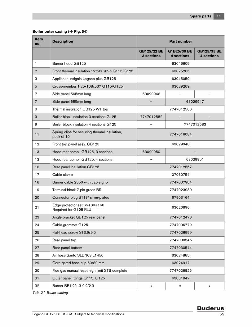
11Spare parts
Logano GB125 BE US/CA - Subject to technical modifications. 55
Boiler outer casing ( Fig. 54)
Item no.
Description Part number
GB125/22 BE3 sections
G1B25/30 BE4 sections
GB125/35 BE4 sections
1 Burner hood GB125 63046609
2 Front thermal insulation 12x580x695 G115/G125 63025265
3 Appliance insignia Logano plus GB125 63045050
5 Cross-member 1.25x108x537 G115/G125 63029209
7 Side panel 565mm long 63029946 – –
7 Side panel 685mm long – 63029947
8 Thermal insulation GB125 WT top 7747012560
9 Boiler block insulation 3 sections G125 7747012582 – –
9 Boiler block insulation 4 sections G125 – 7747012583
11Spring clips for securing thermal insulation, pack of 10
7747016084
12 Front top panel assy. GB125 63029948
13 Hood rear compl. GB125, 3 sections 63029950 –
13 Hood rear compl. GB125, 4 sections – 63029951
16 Rear panel insulation GB125 7747012557
17 Cable clamp 07060754
18 Burner cable 2350 with cable grip 7747007984
19 Terminal block 7-pin green BR 7747023989
20 Connector plug ST18/ silver-plated 67903164
21Edge protector set 65+80+160Required for G125 RLU
63020896
23 Angle bracket GB125 rear panel 7747012473
24 Cable grommet G125 7747006779
25 Flat-head screw ST3.9x9.5 7747026999
26 Rear panel top 7747030545
27 Rear panel bottom 7747030544
28 Air hose Santo SLDN63 L1450 63024885
29 Corrugated hose clip 60/80 mm 63024917
30 Flue gas manual reset high limit STB complete 7747026825
31 Outer panel fixings G115, G125 63031847
32 Burner BE1.2/1.3-2.2/2.3 x x x
Tab. 21 Boiler casing
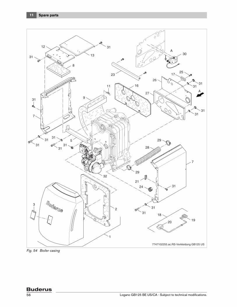
11 Spare parts
Logano GB125 BE US/CA - Subject to technical modifications.56
Fig. 54 Boiler casing
01
23
4
65
A
A
7747102255.ac.RS-Verkleidung GB125 US
13
12 31
25
24
29
28
29
31
8
16
30
11
31
7
31
31
32
19
31
31
312
1
3
3131
5
7
3121
18
20
17
31
31
31
31
9
23
27
26
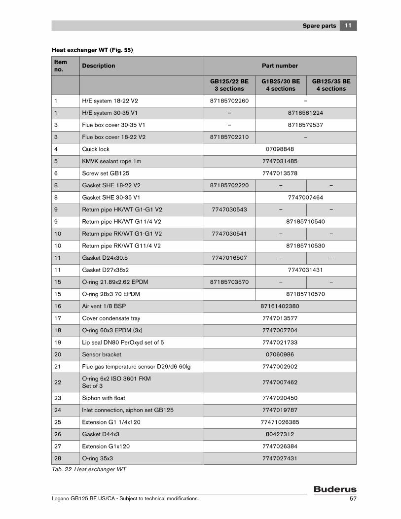
11Spare parts
Logano GB125 BE US/CA - Subject to technical modifications. 57
Heat exchanger WT (Fig. 55)
Item no.
Description Part number
GB125/22 BE3 sections
G1B25/30 BE4 sections
GB125/35 BE4 sections
1 H/E system 18-22 V2 87185702260 –
1 H/E system 30-35 V1 – 8718581224
3 Flue box cover 30-35 V1 – 8718579537
3 Flue box cover 18-22 V2 87185702210 –
4 Quick lock 07098848
5 KMVK sealant rope 1m 7747031485
6 Screw set GB125 7747013578
8 Gasket SHE 18-22 V2 87185702220 – –
8 Gasket SHE 30-35 V1 7747007464
9 Return pipe HK/WT G1-G1 V2 7747030543 – –
9 Return pipe HK/WT G11/4 V2 87185710540
10 Return pipe RK/WT G1-G1 V2 7747030541 – –
10 Return pipe RK/WT G11/4 V2 87185710530
11 Gasket D24x30.5 7747016507 – –
11 Gasket D27x38x2 7747031431
15 O-ring 21.89x2.62 EPDM 87185703570 – –
15 O-ring 28x3 70 EPDM 87185710570
16 Air vent 1/8 BSP 87161402380
17 Cover condensate tray 7747013577
18 O-ring 60x3 EPDM (3x) 7747007704
19 Lip seal DN80 PerOxyd set of 5 7747021733
20 Sensor bracket 07060986
21 Flue gas temperature sensor D29/d6 60lg 7747002902
22O-ring 6x2 ISO 3601 FKMSet of 3
7747007462
23 Siphon with float 7747020450
24 Inlet connection, siphon set GB125 7747019787
25 Extension G1 1/4x120 77471026385
26 Gasket D44x3 80427312
27 Extension G1x120 7747026384
28 O-ring 35x3 7747027431
Tab. 22 Heat exchanger WT

11 Spare parts
Logano GB125 BE US/CA - Subject to technical modifications.58
29 Siphon fixing bracket V2 7747030548
30 Pipe clip G125ECO/GB125 7747007705
31 Thermal insulation GB125 WT 18-22 kW 7747012558 –
31 Thermal insulation GB125 WT 30-35 kW – 7747012559
33Boiler adapter, concentric 80/125 GB125 V2(included with venting system)
7747016312
34 Gasket flue gas distributor 87185702200 8718579535
35 Spacer sleeve 17.2x2.1x68 87185702230
36 Spring clip d=32.6/22 7747030542 – –
36 Spring clip d=38.2/28 – 87185710560
37 Spring plug D26 7747030559
38 Spacer sleeve 17.2x2.1 87185708250
99 Siphon gasket set GB125 SB105 7747016504
Item no.
Description Part number
GB125/22 BE3 sections
G1B25/30 BE4 sections
GB125/35 BE4 sections
Tab. 22 Heat exchanger WT
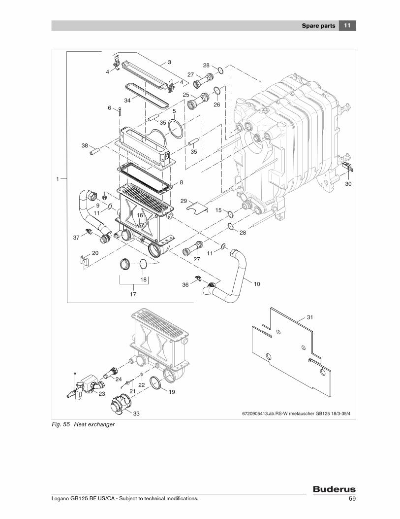
11Spare parts
Logano GB125 BE US/CA - Subject to technical modifications. 59
Fig. 55 Heat exchanger
6720905413.ab.RS-W rmetauscher GB125 18/3-35/4
29
30
31
5
25
35
35
28
159
11
1127
10
27
34
28
26
4
6
4
1
3
8
16
17
20
37
36
19
33
24
23
18
2221
38
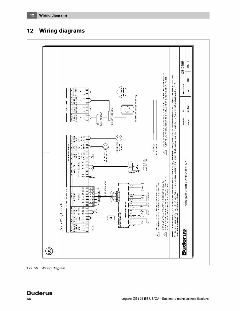
12 Wiring diagrams
Logano GB125 BE US/CA - Subject to technical modifications.60
12 Wiring diagrams
Fig. 56 Wiring diagram

Index
Logano GB125 BE US/CA - Subject to technical modifications. 61
Index
AAmbient conditions ....................................................... 10
BB-kit components ........................................................... 7B-kit Installation ............................................................ 22Boiler output .................................................................. 8Boiler type ..................................................................... 8Burner, notes on commissioning ..................................... 33
CCheck the manual reset high limit (STB)........................... 34Checking for leaks (heating water) .................................. 24Commissioning ............................................................ 31
log.......................................................................... 35Connecting power supply .............................................. 29Connecting the fuel supply............................................. 25Connections .................................................................. 8Correcting burner faults ................................................. 48
DDimensions.................................................................... 8Dirt trap....................................................................... 22
EExamples of Installations ................................................ 49
FFuel, operating conditions .............................................. 10
HHeat exchanger baffles, checking position........................ 32Heat exchanger baffles, removing.................................... 38Heat exchanger heater flue, cleaning ............................... 38Heating circuits, multiple................................................ 49Heating system emergency shut-off switch ....................... 36
IInstallation diagram ....................................................... 23Installation of drain valve ................................................ 23Installation room ........................................................... 10Installing outer casing panels.......................................... 30Installing strain relief...................................................... 30Installing the burner door jacket ...................................... 30Installing the control panel.............................................. 27Installing the temperature sensor assembly....................... 28
LLine voltage ................................................................. 10Log, commissioning ...................................................... 35Logs, inspection and maintenance .................................. 45
MMain power switch........................................................ 36Main shut-off valve ........................................................ 32Maintenance, regular ..................................................... 37
Mounting the adjustable feet .......................................... 16
OOn-off switch ............................................................... 36Operating conditions....................................................... 9
PPermissible operating pressure......................................... 8Power supply ............................................................... 10Pressure gauge/thermometer ................................... 31, 43Pressure test port ......................................................... 33
RRated heat output ........................................................... 8Removing burner door panel .......................................... 12Removing the boiler cover.............................................. 27Replacing sealant rope .................................................. 38Reversing boiler door .................................................... 15Reversing the burner door.............................................. 15
SSafety instructions .......................................................... 3Safety valve ..................................................... 22, 24, 32Scope of delivery............................................................ 7Shutting down.............................................................. 36Site test pressure ................................................... 11, 24Spare parts lists ........................................................... 52Supply temperature......................................................... 8
TTechnical specifications................................................... 8Thermometer/pressure gauge................................... 31, 43Topping up .................................................................. 43Transporting with boiler trolley/sack truck......................... 13Troubleshooting ........................................................... 48
WWall clearances............................................................ 14Water quality ............................................................... 11Wet cleaning ............................................................... 39

Logano GB125 BE US/CA - Subject to technical modifications.62
Notes

Logano GB125 BE US/CA - Subject to technical modifications. 63
Notes