Embed Size (px)
Citation preview
S SERIES PERISTALTIC PUMPINSTALLATION AND MAINTENANCE MANUAL
PERISTALTIC METERING PUMPS SINCE 1957
TO BE INSTALLED AND MAINTAINED BY PROPERLY TRAINED PROFESSIONAL INSTALLERONLY. READ MANUAL & LABELS FOR ALL SAFETY INFORMATION & INSTRUCTIONS.
WARNING
www.stenner.com2
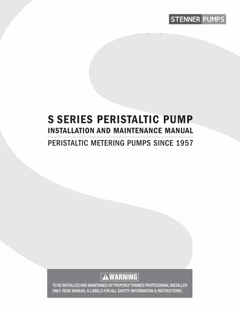
TABLE OF CONTENTS
WARRANTY AND SERVICE POLICY .......................................... 3
SAFETY INSTRUCTIONS ............................................................COVER, 4-5, 65, 67-68, 70, 72-73,76, 78, 79, 81-85, 89, 94
FLOW RATE OUTPUT CHARTS ................................................. 6
MATERIALS OF CONSTRUCTION ............................................. 7
ACCESSORY CHECKLIST ....................................................... 8
GENERAL INFORMATION .................................................. 9-11
CONFIGURATION ........................................................... 12-28
CONTROL MODES ...........................................................29-52
OPERATING DISPLAY ......................................................53-64
CONNECTIONS ...............................................................65-77
INSTALLATION ............................................................... 78-84
TROUBLESHOOTING ....................................................... 85-88
TUBE REPLACEMENT ..................................................... 89-93
CLEANING THE POINT OF INJECTION ............................... 94-95
PARTS ........................................................................ 96-100
WALL MOUNT BRACKET MOUNTING HOLE DIMENSIONS ...... 101
IMS 070617
US and Canada 800.683.2378, International 904.641.1666 3
WARRANTY AND CUSTOMER SERVICE
LIMITED WARRANTYStenner Pump Company will for a period of one (1) year from the date of purchase (proof of purchase required) repair orreplace – at our option – all defective parts. Stenner is not responsible for any removal or installation costs. Pump tubeassemblies and rubber components are considered perishable and are not covered in this warranty. Pump tube will bereplaced each time a pump is in for service, unless otherwise specified. The cost of the pump tube replacement will bethe responsibility of the customer. Stenner will incur shipping costs for warranty products shipped from our factory inJacksonville, Florida. Any tampering with major components, chemical damage, faulty wiring, weather conditions, waterdamage, power surges, or products not used with reasonable care and maintained in accordance with the instructionswill void the warranty. Stenner limits its liability solely to the cost of the original product. We make no other warrantyexpressed or implied.
RETURNSStenner offers a 30-day return policy on factory direct purchases. Except as otherwise provided, no merchandise will beaccepted for return after 30 days from purchase. To return merchandise at any time, call Stenner at 800.683.2378 for aReturn Merchandise Authorization (RMA) number. A 15% re-stocking fee will be applied. Include a copy of your invoice orpacking slip with your return.
DAMAGED OR LOST SHIPMENTSAll truck shipments: Check your order immediately upon arrival. All damage must be noted on the delivery receipt. CallStenner Customer Service at 800.683.2378 for all shortages and damages within seven (7) days of receipt.
SERVICE & REPAIRSBefore returning a pump for warranty or repair, remove chemical from pump tube by running water through the tube, andthen run the pump dry. Following expiration of the warranty period, Stenner Pump Company will clean and overhaul anyStenner metering pump for a minimum labor charge plus necessary replacement parts and shipping. All metering pumpsreceived for overhaul will be restored to their original condition. The customer will be charged for missing parts unlessspecific instructions are given. To return merchandise for repair, call Stenner at 800.683.2378 or 904.641.1666 for aReturn Merchandise Authorization (RMA) number.
DISCLAIMERThe information contained in this manual is not intended for specific application purposes. Stenner Pump Companyreserves the right to make changes to prices, products, and specifications at any time without prior notice.
TRADEMARKSSantoprene® is a registered trademark of Exxon Mobil Corporation.Versilon® is a registered trademark of Saint-Gobain Performance Plastics.Pellethane® is a registered trademark of Lubrizol Advanced Materials, Inc.Hastelloy® is a registered trademark of Haynes International, Inc. AquaShield™ is a trademark of Houghton International.
www.stenner.com4
SAFETY INSTRUCTIONS
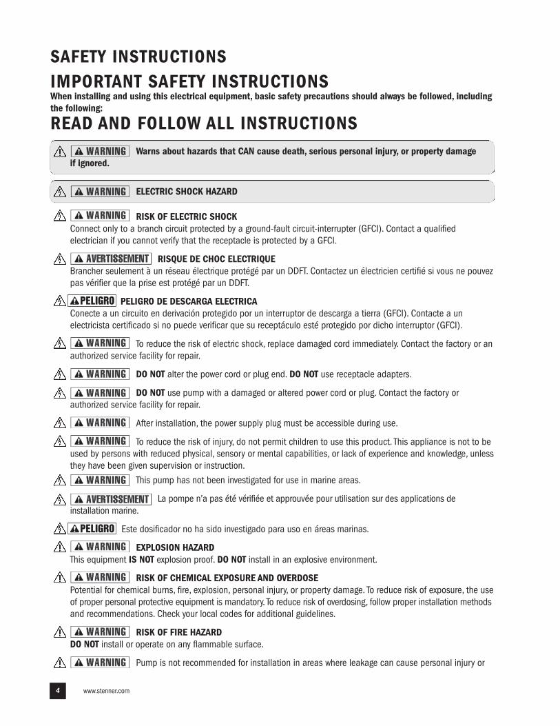
Warns about hazards that CAN cause death, serious personal injury, or property damage if ignored.
ELECTRIC SHOCK HAZARD
RISK OF ELECTRIC SHOCK Connect only to a branch circuit protected by a ground-fault circuit-interrupter (GFCI). Contact a qualifiedelectrician if you cannot verify that the receptacle is protected by a GFCI.
RISQUE DE CHOC ELECTRIQUEBrancher seulement à un réseau électrique protégé par un DDFT. Contactez un électricien certifié si vous ne pouvezpas vérifier que la prise est protégé par un DDFT.
PELIGRO DE DESCARGA ELECTRICAConecte a un circuito en derivación protegido por un interruptor de descarga a tierra (GFCI). Contacte a unelectricista certificado si no puede verificar que su receptáculo esté protegido por dicho interruptor (GFCI).
To reduce the risk of electric shock, replace damaged cord immediately. Contact the factory or anauthorized service facility for repair.
DO NOT alter the power cord or plug end. DO NOT use receptacle adapters.
DO NOT use pump with a damaged or altered power cord or plug. Contact the factory orauthorized service facility for repair.
After installation, the power supply plug must be accessible during use.
To reduce the risk of injury, do not permit children to use this product. This appliance is not to beused by persons with reduced physical, sensory or mental capabilities, or lack of experience and knowledge, unlessthey have been given supervision or instruction.
This pump has not been investigated for use in marine areas.
La pompe n’a pas été vérifiée et approuvée pour utilisation sur des applications deinstallation marine.
Este dosificador no ha sido investigado para uso en áreas marinas.
EXPLOSION HAZARDThis equipment IS NOT explosion proof. DO NOT install in an explosive environment.
RISK OF CHEMICAL EXPOSURE AND OVERDOSEPotential for chemical burns, fire, explosion, personal injury, or property damage. To reduce risk of exposure, the useof proper personal protective equipment is mandatory. To reduce risk of overdosing, follow proper installation methodsand recommendations. Check your local codes for additional guidelines.
RISK OF FIRE HAZARDDO NOT install or operate on any flammable surface.
Pump is not recommended for installation in areas where leakage can cause personal injury or
PELIGRO
PELIGRO
IMPORTANT SAFETY INSTRUCTIONSWhen installing and using this electrical equipment, basic safety precautions should always be followed, includingthe following:
READ AND FOLLOW ALL INSTRUCTIONS
US and Canada 800.683.2378, International 904.641.1666 5
SAFETY INSTRUCTIONS continued
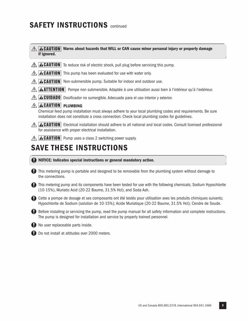
Warns about hazards that WILL or CAN cause minor personal injury or property damage if ignored.
To reduce risk of electric shock, pull plug before servicing this pump.
This pump has been evaluated for use with water only.
Non-submersible pump. Suitable for indoor and outdoor use.
Pompe non submersible. Adaptée à une utilisation aussi bien à l’intérieur qu’à l’extérieur.
Dosificador no sumergible. Adecuado para el uso interior y exterior.
PLUMBINGChemical feed pump installation must always adhere to your local plumbing codes and requirements. Be sureinstallation does not constitute a cross connection. Check local plumbing codes for guidelines.
Electrical installation should adhere to all national and local codes. Consult licensed professionalfor assistance with proper electrical installation.
Pump uses a class 2 switching power supply.
SAVE THESE INSTRUCTIONSNOTICE: Indicates special instructions or general mandatory action.
This metering pump is portable and designed to be removable from the plumbing system without damage to the connections.
This metering pump and its components have been tested for use with the following chemicals; Sodium Hypochlorite(10-15%), Muriatic Acid (20-22 Baume, 31.5% Hcl), and Soda Ash.
Cette a pompe de dosage et ses composants ont été testés pour utilisation avec les produits chimiques suivants;Hypochlorite de Sodium (solution de 10-15%); Acide Muriatique (20-22 Baume, 31.5% Hcl); Cendre de Soude.
Before installing or servicing the pump, read the pump manual for all safety information and complete instructions.The pump is designed for installation and service by properly trained personnel.
No user replaceable parts inside.
Do not install at altitudes over 2000 meters.
CAUTION
CAUTION
CAUTION
CAUTION
CUIDADO
ATTENTION
CAUTION
CAUTION
CAUTION
www.stenner.com6
FLOW RATE OUTPUT CHARTS
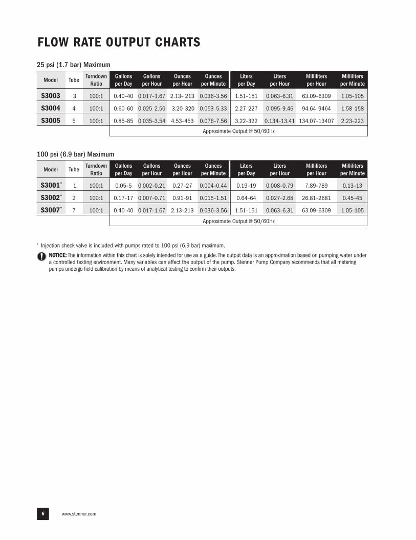
25 psi (1.7 bar) Maximum
Model Tube Turndown Gallons Gallons Ounces Ounces Liters Liters Milliliters Milliliters
Ratio per Day per Hour per Hour per Minute per Day per Hour per Hour per Minute
S3003 3 100:1 0.40–40 0.017–1.67 2.13– 213 0.036–3.56 1.51–151 0.063–6.31 63.09–6309 1.05–105
S3004 4 100:1 0.60–60 0.025–2.50 3.20–320 0.053–5.33 2.27–227 0.095–9.46 94.64–9464 1.58–158
S3005 5 100:1 0.85–85 0.035–3.54 4.53–453 0.076–7.56 3.22–322 0.134–13.41 134.07–13407 2.23–223
NOTICE: The information within this chart is solely intended for use as a guide. The output data is an approximation based on pumping water undera controlled testing environment. Many variables can affect the output of the pump. Stenner Pump Company recommends that all meteringpumps undergo field calibration by means of analytical testing to confirm their outputs.
* Injection check valve is included with pumps rated to 100 psi (6.9 bar) maximum.
Model Tube Turndown Gallons Gallons Ounces Ounces Liters Liters Milliliters Milliliters
Ratio per Day per Hour per Hour per Minute per Day per Hour per Hour per Minute
S3001* 1 100:1 0.05–5 0.002–0.21 0.27–27 0.004–0.44 0.19–19 0.008–0.79 7.89–789 0.13–13
S3002* 2 100:1 0.17–17 0.007–0.71 0.91–91 0.015–1.51 0.64–64 0.027–2.68 26.81–2681 0.45–45
S3007* 7 100:1 0.40–40 0.017–1.67 2.13–213 0.036–3.56 1.51–151 0.063–6.31 63.09–6309 1.05–105
100 psi (6.9 bar) Maximum
Approximate Output @ 50/60Hz
Approximate Output @ 50/60Hz
US and Canada 800.683.2378, International 904.641.1666 7
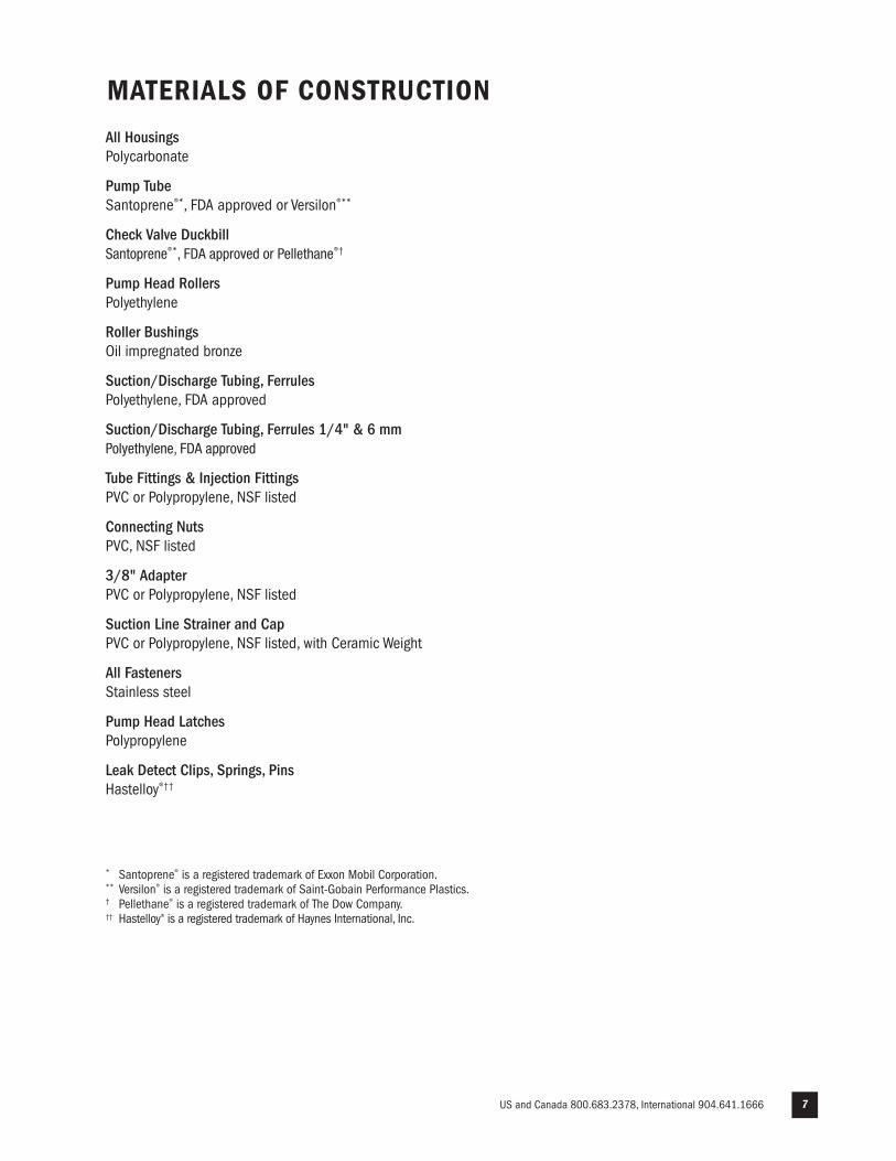
MATERIALS OF CONSTRUCTION
All HousingsPolycarbonate
Pump TubeSantoprene®*, FDA approved or Versilon®**
Check Valve DuckbillSantoprene®*, FDA approved or Pellethane®†
Pump Head RollersPolyethylene
Roller BushingsOil impregnated bronze
Suction/Discharge Tubing, FerrulesPolyethylene, FDA approved
Suction/Discharge Tubing, Ferrules 1/4" & 6 mmPolyethylene, FDA approved
Tube Fittings & Injection Fittings PVC or Polypropylene, NSF listed
Connecting NutsPVC, NSF listed
3/8" AdapterPVC or Polypropylene, NSF listed
Suction Line Strainer and CapPVC or Polypropylene, NSF listed, with Ceramic Weight
All Fasteners Stainless steel
Pump Head Latches Polypropylene
Leak Detect Clips, Springs, PinsHastelloy®††
* Santoprene® is a registered trademark of Exxon Mobil Corporation.** Versilon® is a registered trademark of Saint-Gobain Performance Plastics.† Pellethane® is a registered trademark of The Dow Company.†† Hastelloy® is a registered trademark of Haynes International, Inc.
www.stenner.com8
ACCESSORY CHECKLIST
3 Connecting Nuts 1/4" or 3/8"
3 Ferrules 1/4" or 6 mm Europe
1 Injection Fitting 25 psi (1.7 bar) max. or 1 Injection Check Valve 100 psi (6.9 bar) max.
1 Weighted Suction Line Strainer 1/4", 3/8" or 6 mm Europe
1 20' Roll of Suction/Discharge Tubing 1/4" or 3/8", white, UV black or 6 mm white Europe
1 Additional Pump Tube
2 Additional Latches
1 Mounting Bracket
1 Quick Start Guide
US and Canada 800.683.2378, International 904.641.1666 9
GENERAL INFORMATION SUMMARY
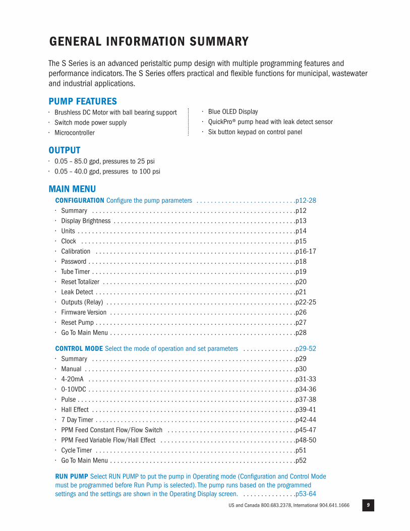
CONFIGURATION Configure the pump parameters . . . . . . . . . . . . . . . . . . . . . . . . . . . .p12-28• Summary . . . . . . . . . . . . . . . . . . . . . . . . . . . . . . . . . . . . . . . . . . . . . . . . . . . . . . . . .p12• Display Brightness . . . . . . . . . . . . . . . . . . . . . . . . . . . . . . . . . . . . . . . . . . . . . . . . . . .p13• Units . . . . . . . . . . . . . . . . . . . . . . . . . . . . . . . . . . . . . . . . . . . . . . . . . . . . . . . . . . . . .p14• Clock . . . . . . . . . . . . . . . . . . . . . . . . . . . . . . . . . . . . . . . . . . . . . . . . . . . . . . . . . . . .p15• Calibration . . . . . . . . . . . . . . . . . . . . . . . . . . . . . . . . . . . . . . . . . . . . . . . . . . . . . . . .p16-17• Password . . . . . . . . . . . . . . . . . . . . . . . . . . . . . . . . . . . . . . . . . . . . . . . . . . . . . . . . . .p18• Tube Timer . . . . . . . . . . . . . . . . . . . . . . . . . . . . . . . . . . . . . . . . . . . . . . . . . . . . . . . . .p19• Reset Totalizer . . . . . . . . . . . . . . . . . . . . . . . . . . . . . . . . . . . . . . . . . . . . . . . . . . . . . .p20• Leak Detect . . . . . . . . . . . . . . . . . . . . . . . . . . . . . . . . . . . . . . . . . . . . . . . . . . . . . . . .p21• Outputs (Relay) . . . . . . . . . . . . . . . . . . . . . . . . . . . . . . . . . . . . . . . . . . . . . . . . . . . . .p22-25• Firmware Version . . . . . . . . . . . . . . . . . . . . . . . . . . . . . . . . . . . . . . . . . . . . . . . . . . . .p26• Reset Pump . . . . . . . . . . . . . . . . . . . . . . . . . . . . . . . . . . . . . . . . . . . . . . . . . . . . . . . .p27• Go To Main Menu . . . . . . . . . . . . . . . . . . . . . . . . . . . . . . . . . . . . . . . . . . . . . . . . . . . .p28
CONTROL MODE Select the mode of operation and set parameters . . . . . . . . . . . . . . .p29-52• Summary . . . . . . . . . . . . . . . . . . . . . . . . . . . . . . . . . . . . . . . . . . . . . . . . . . . . . . . . .p29• Manual . . . . . . . . . . . . . . . . . . . . . . . . . . . . . . . . . . . . . . . . . . . . . . . . . . . . . . . . . . .p30• 4-20mA . . . . . . . . . . . . . . . . . . . . . . . . . . . . . . . . . . . . . . . . . . . . . . . . . . . . . . . . . .p31-33 • 0-10VDC . . . . . . . . . . . . . . . . . . . . . . . . . . . . . . . . . . . . . . . . . . . . . . . . . . . . . . . . . .p34-36• Pulse . . . . . . . . . . . . . . . . . . . . . . . . . . . . . . . . . . . . . . . . . . . . . . . . . . . . . . . . . . . . .p37-38• Hall Effect . . . . . . . . . . . . . . . . . . . . . . . . . . . . . . . . . . . . . . . . . . . . . . . . . . . . . . . . .p39-41• 7 Day Timer . . . . . . . . . . . . . . . . . . . . . . . . . . . . . . . . . . . . . . . . . . . . . . . . . . . . . . . .p42-44• PPM Feed Constant Flow/Flow Switch . . . . . . . . . . . . . . . . . . . . . . . . . . . . . . . . . . . .p45-47• PPM Feed Variable Flow/Hall Effect . . . . . . . . . . . . . . . . . . . . . . . . . . . . . . . . . . . . . .p48-50• Cycle Timer . . . . . . . . . . . . . . . . . . . . . . . . . . . . . . . . . . . . . . . . . . . . . . . . . . . . . . . .p51• Go To Main Menu . . . . . . . . . . . . . . . . . . . . . . . . . . . . . . . . . . . . . . . . . . . . . . . . . . . .p52
RUN PUMP Select RUN PUMP to put the pump in Operating mode (Configuration and Control Modemust be programmed before Run Pump is selected). The pump runs based on the programmedsettings and the settings are shown in the Operating Display screen. . . . . . . . . . . . . . . .p53-64
The S Series is an advanced peristaltic pump design with multiple programming features andperformance indicators. The S Series offers practical and flexible functions for municipal, wastewaterand industrial applications.
PUMP FEATURES• Brushless DC Motor with ball bearing support• Switch mode power supply• Microcontroller
OUTPUT• 0.05 – 85.0 gpd, pressures to 25 psi• 0.05 – 40.0 gpd, pressures to 100 psi
MAIN MENU
• Blue OLED Display• QuickPro® pump head with leak detect sensor• Six button keypad on control panel
www.stenner.com10
GENERAL INFORMATION SUMMARY continued
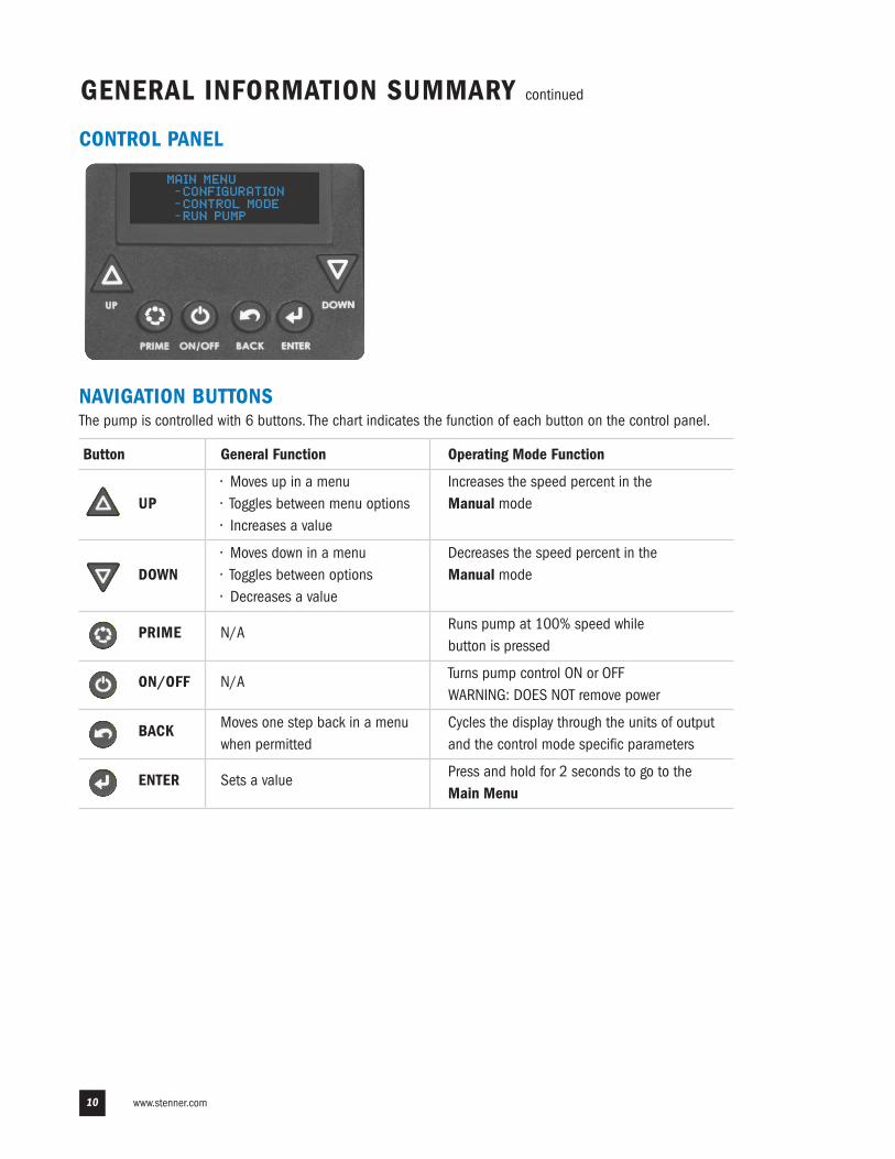
CONTROL PANEL
NAVIGATION BUTTONS The pump is controlled with 6 buttons. The chart indicates the function of each button on the control panel.
Button General Function Operating Mode Function
• Moves up in a menu Increases the speed percent in theUP • Toggles between menu options Manual mode
• Increases a value
• Moves down in a menu Decreases the speed percent in theDOWN • Toggles between options Manual mode
• Decreases a value
PRIME N/A Runs pump at 100% speed while button is pressed
ON/OFF N/A Turns pump control ON or OFF WARNING: DOES NOT remove power
BACK Moves one step back in a menu Cycles the display through the units of output when permitted and the control mode specific parameters
ENTER Sets a value Press and hold for 2 seconds to go to the Main Menu
MAIN MENU
-CONFIGURATION
-CONTROL MODE
-RUN PUMP
US and Canada 800.683.2378, International 904.641.1666 11
GENERAL INFORMATION SUMMARY
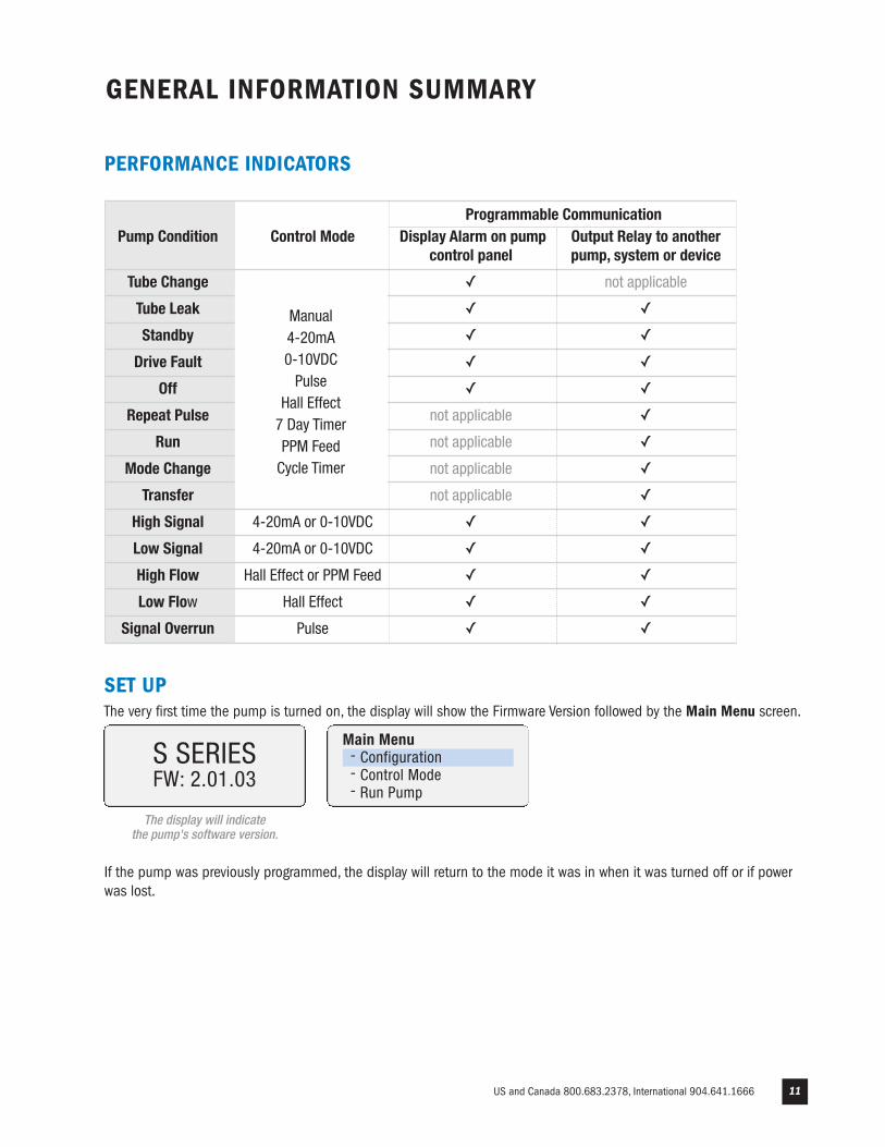
SET UPThe very first time the pump is turned on, the display will show the Firmware Version followed by the Main Menu screen.
If the pump was previously programmed, the display will return to the mode it was in when it was turned off or if powerwas lost.
Main Menu- Configuration- Control Mode- Run Pump
FW: 2.01.03S SERIES
The display will indicate the pump's software version.
PERFORMANCE INDICATORS
Programmable Communication
Pump Condition Control Mode Display Alarm on pump Output Relay to another
control panel pump, system or device
Tube Change ✓ not applicable
Tube Leak ✓ ✓
Standby ✓ ✓
Drive Fault ✓ ✓
Off ✓ ✓
Repeat Pulse not applicable ✓
Run not applicable ✓
Mode Change not applicable ✓
Transfer not applicable ✓
High Signal 4-20mA or 0-10VDC ✓ ✓
Low Signal 4-20mA or 0-10VDC ✓ ✓
High Flow Hall Effect or PPM Feed ✓ ✓
Low Flow Hall Effect ✓ ✓
Signal Overrun Pulse ✓ ✓
Manual4-20mA0-10VDCPulse
Hall Effect7 Day TimerPPM FeedCycle Timer
www.stenner.com12
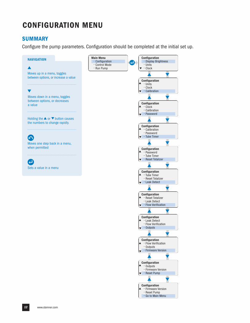
CONFIGURATION MENU
Main Menu- Configuration- Control Mode- Run Pump
Configuration- Display Brightness- Units- Clock
Configuration- Units- Clock- Calibration
Configuration- Clock- Calibration- Password
Configuration- Calibration- Password- Tube Timer
Configuration- Password- Tube Timer- Reset Totalizer
Configuration- Tube Timer- Reset Totalizer- Leak Detect
Configuration- Reset Totalizer- Leak Detect- Flow Verification
Configuration- Leak Detect- Flow Verification- Outputs
Configuration- Flow Verification- Outputs- Firmware Version
Configuration- Outputs- Firmware Version- Reset Pump
Configuration- Firmware Version- Reset Pump- Go to Main Menu
SUMMARYConfigure the pump parameters. Configuration should be completed at the initial set up.
NAVIGATION
Holding the or button causesthe numbers to change rapidly.
Moves up in a menu, togglesbetween options, or increase a value
Moves down in a menu, togglesbetween options, or decreases a value
Sets a value in a menu
Moves one step back in a menu,when permitted
Returns to Configuration menu
US and Canada 800.683.2378, International 904.641.1666 13
Display BrightnessConfiguration- Display Brightness- Units- Clock
100%adjust set
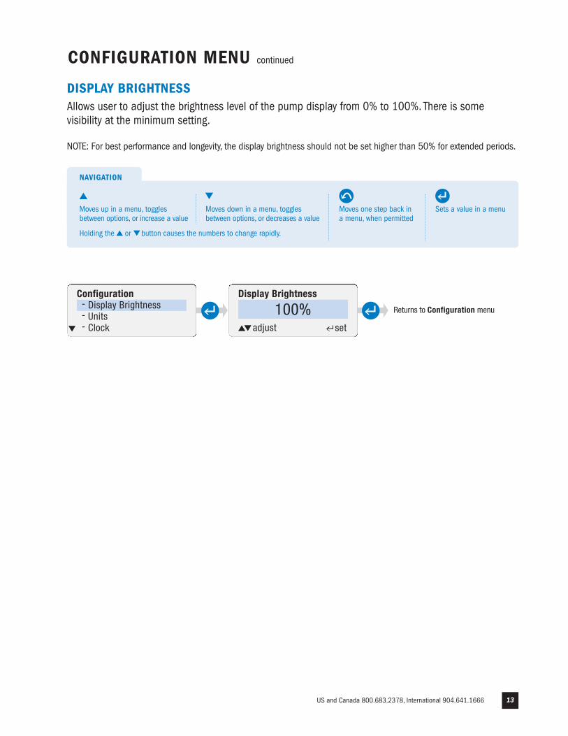
CONFIGURATION MENU continued
DISPLAY BRIGHTNESSAllows user to adjust the brightness level of the pump display from 0% to 100%. There is somevisibility at the minimum setting.
NOTE: For best performance and longevity, the display brightness should not be set higher than 50% for extended periods.
Sets a value in a menu
NAVIGATION
Moves one step back ina menu, when permitted
Moves up in a menu, togglesbetween options, or increase a value
Moves down in a menu, togglesbetween options, or decreases a value
Holding the or button causes the numbers to change rapidly.
www.stenner.com14
UnitsConfiguration- Display Brightness- Units- Clock
Gallons
Units
Liters
Returns to Configuration menu.
Returns to Configuration menu.
adjust set
adjust set
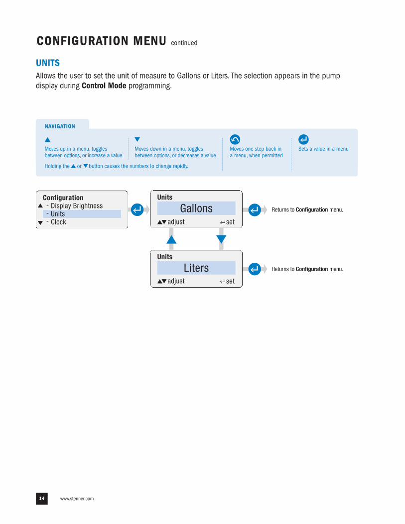
CONFIGURATION MENU continued
UNITSAllows the user to set the unit of measure to Gallons or Liters. The selection appears in the pumpdisplay during Control Mode programming.
Sets a value in a menu
NAVIGATION
Moves one step back ina menu, when permitted
Moves up in a menu, togglesbetween options, or increase a value
Moves down in a menu, togglesbetween options, or decreases a value
Sets a value in a menu
NAVIGATION
Moves one step back ina menu, when permitted
Moves up in a menu, togglesbetween options, or increase a value
Moves down in a menu, togglesbetween options, or decreases a value
Holding the or button causes the numbers to change rapidly.
US and Canada 800.683.2378, International 904.641.1666 15
Today isConfiguration- Display Brightness- Units- Clock
SundayThe time is
00:00:00adjustsun- sat set set
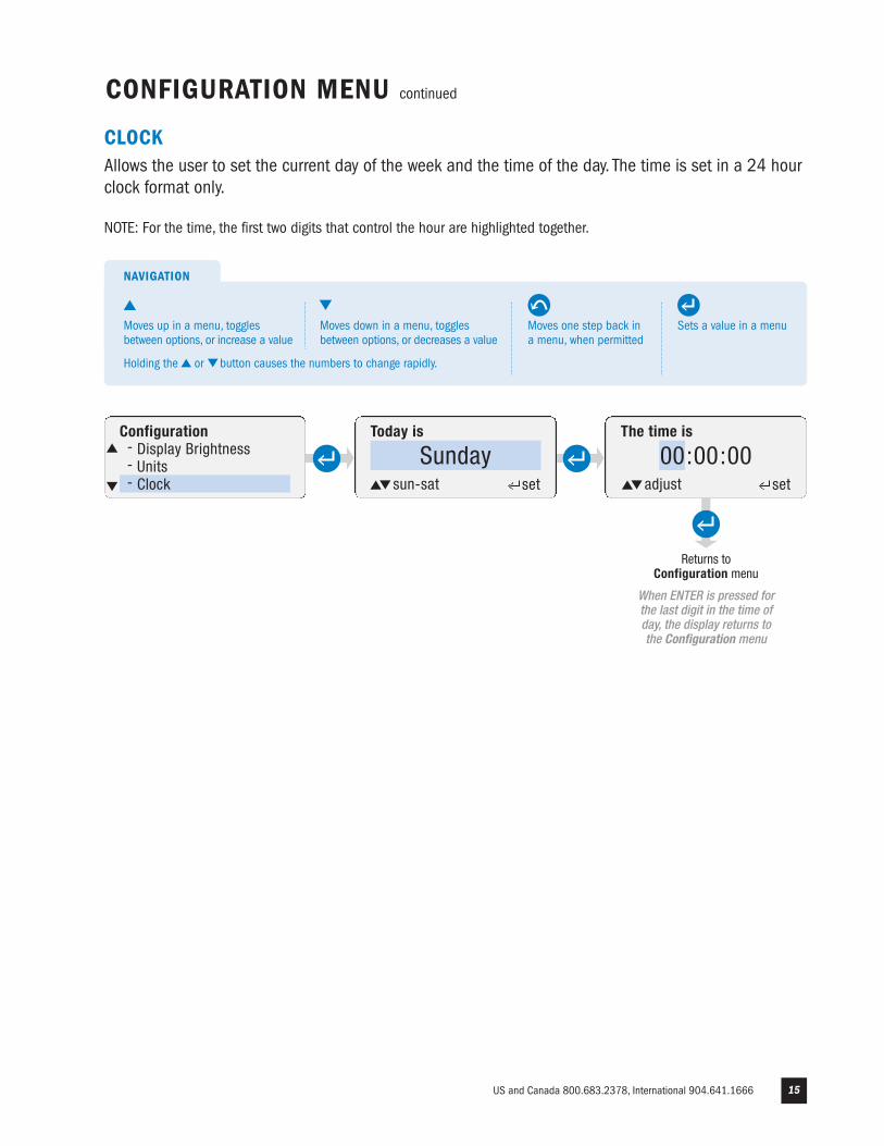
CONFIGURATION MENU continued
CLOCKAllows the user to set the current day of the week and the time of the day. The time is set in a 24 hourclock format only.
NOTE: For the time, the first two digits that control the hour are highlighted together.
Returns to Configuration menu
When ENTER is pressed forthe last digit in the time ofday, the display returns tothe Configuration menu
Sets a value in a menu
NAVIGATION
Moves one step back ina menu, when permitted
Moves up in a menu, togglesbetween options, or increase a value
Moves down in a menu, togglesbetween options, or decreases a value
Holding the or button causes the numbers to change rapidly.
To Configuration menu
Calibration- GPD/LPD Calibration- Signal Calibration- GO TO CONFIG MENU
CONFIGURATION MENU continued
Enter max pump flow
_ _ 0.0 GPDadjust set
Calibration- GPD/LPD Calibration- Signal Calibration- GO TO CONFIG MENU
Calibration- GPD/LPD Calibration- Signal Calibration- GO TO CONFIG MENU
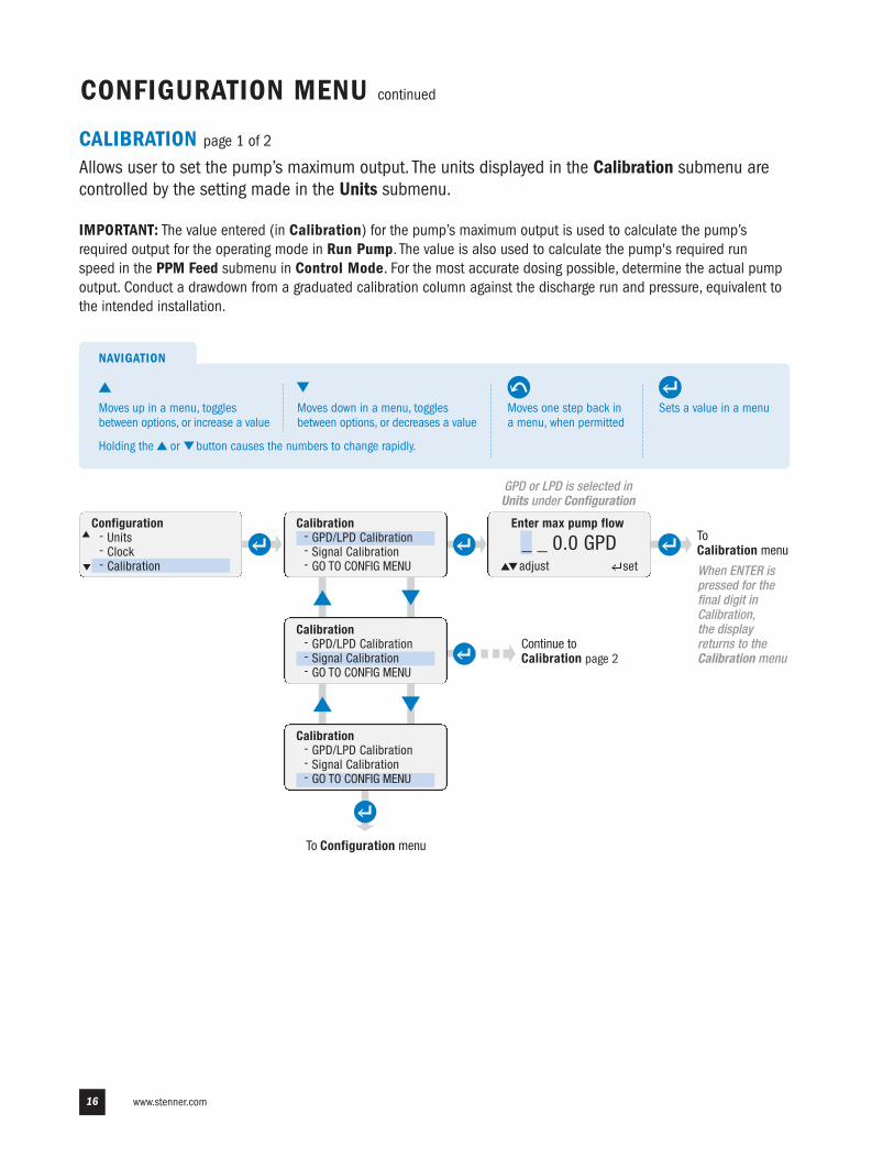
CALIBRATION page 1 of 2
Allows user to set the pump’s maximum output. The units displayed in the Calibration submenu arecontrolled by the setting made in the Units submenu.
IMPORTANT: The value entered (in Calibration) for the pump’s maximum output is used to calculate the pump’s required output for the operating mode in Run Pump. The value is also used to calculate the pump's required run speed in the PPM Feed submenu in Control Mode. For the most accurate dosing possible, determine the actual pumpoutput. Conduct a drawdown from a graduated calibration column against the discharge run and pressure, equivalent tothe intended installation.
GPD or LPD is selected in Units under Configuration
When ENTER ispressed for thefinal digit inCalibration, the displayreturns to the Calibration menu
Configuration- Units- Clock- Calibration
To Calibration menu
Continue toCalibration page 2
Sets a value in a menu
NAVIGATION
Moves one step back ina menu, when permitted
Moves up in a menu, togglesbetween options, or increase a value
Moves down in a menu, togglesbetween options, or decreases a value
Holding the or button causes the numbers to change rapidly.
www.stenner.com16
To Signal Calibration menu
To Signal Calibration menu
Calibration- GPD/LPD Calibration- Signal Calibration- GO TO CONFIG MENU
Signal Calibration- 4-20mA IN- 0 - 10V IN- 4-20mA OUT
To top ofCalibration menu
Signal Calibration- 0 - 10V IN- 4-20mA OUT- GO TO CAL MENU
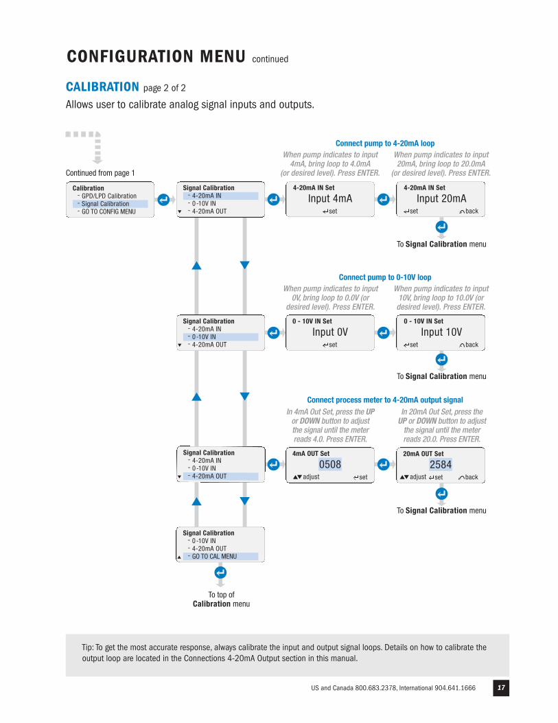
Connect pump to 0-10V loop
CONFIGURATION MENU continued
CALIBRATION page 2 of 2
Allows user to calibrate analog signal inputs and outputs.
0 - 10V IN Set
Input 0V0 - 10V IN Set
Input 10Vset backset
Signal Calibration- 4-20mA IN- 0 - 10V IN- 4-20mA OUT
When pump indicates to input10V, bring loop to 10.0V (ordesired level). Press ENTER.
When pump indicates to input0V, bring loop to 0.0V (or
desired level). Press ENTER.
Signal Calibration- 4-20mA IN- 0 - 10V IN- 4-20mA OUT
Continued from page 1
Connect process meter to 4-20mA output signal
4mA OUT Set
0508adjust set
20mA OUT Set
2584set back
In 20mA Out Set, press theUP or DOWN button to adjustthe signal until the meterreads 20.0. Press ENTER.
In 4mA Out Set, press the UPor DOWN button to adjustthe signal until the meterreads 4.0. Press ENTER.
Input 4mA4-20mA IN Set
Input 20mAset backset
Connect pump to 4-20mA loop
4-20mA IN Set
When pump indicates to input20mA, bring loop to 20.0mA
(or desired level). Press ENTER.
When pump indicates to input4mA, bring loop to 4.0mA
(or desired level). Press ENTER.
To Signal Calibration menu
Tip: To get the most accurate response, always calibrate the input and output signal loops. Details on how to calibrate theoutput loop are located in the Connections 4-20mA Output section in this manual.
US and Canada 800.683.2378, International 904.641.1666 17
adjust
www.stenner.com18
CONFIGURATION MENU continued
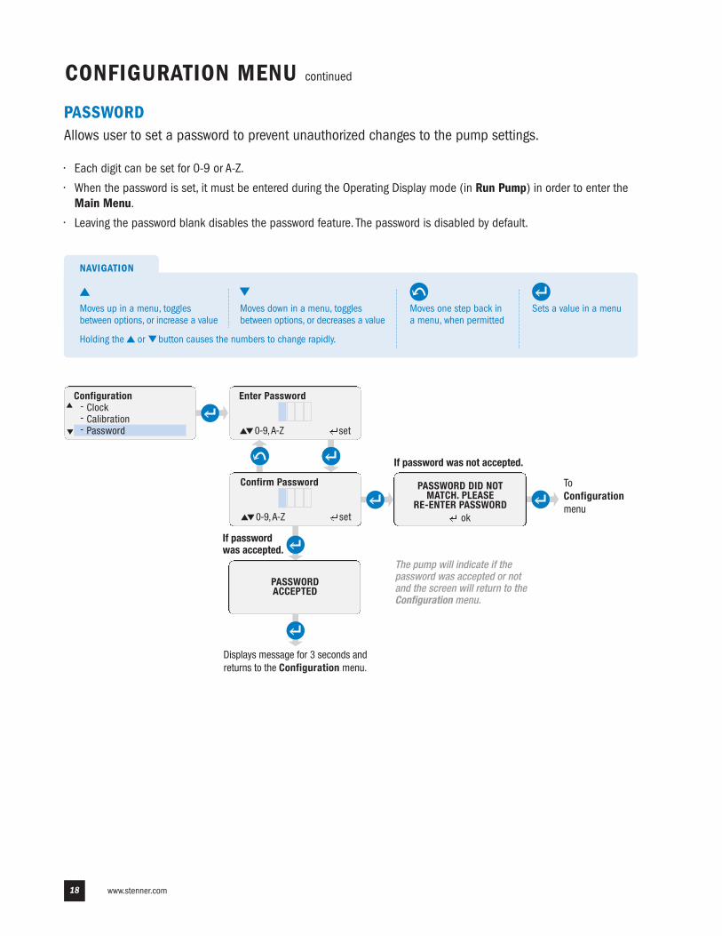
PASSWORDAllows user to set a password to prevent unauthorized changes to the pump settings.
• Each digit can be set for 0-9 or A-Z.
• When the password is set, it must be entered during the Operating Display mode (in Run Pump) in order to enter the Main Menu.
• Leaving the password blank disables the password feature. The password is disabled by default.
The pump will indicate if thepassword was accepted or notand the screen will return to theConfiguration menu.
Displays message for 3 seconds andreturns to the Configuration menu.
PASSWORD DID NOTMATCH. PLEASE
RE-ENTER PASSWORD
Configuration- Clock- Calibration- Password
Enter Password
0-9, A-Z set
Confirm Password
0-9, A-Z set
PASSWORDACCEPTED
ok
If passwordwas accepted.
If password was not accepted.
ToConfigurationmenu
Sets a value in a menu
NAVIGATION
Moves one step back ina menu, when permitted
Moves up in a menu, togglesbetween options, or increase a value
Moves down in a menu, togglesbetween options, or decreases a value
Holding the or button causes the numbers to change rapidly.
Tube Timer- Current Run Time- Set Life Timer- Reset Tube Timer
Tube Timer- Current Run Time- Set Life Timer- Reset Tube Timer
US and Canada 800.683.2378, International 904.641.1666 19
CONFIGURATION MENU continued
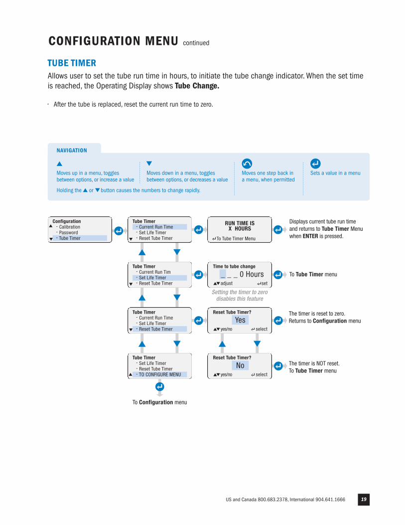
TUBE TIMERAllows user to set the tube run time in hours, to initiate the tube change indicator. When the set timeis reached, the Operating Display shows Tube Change.
• After the tube is replaced, reset the current run time to zero.
To Configuration menu
set back
Tube Timer- Current Run Tim- Set Life Timer- Reset Tube Timer
Reset Tube Timer?
Yesyes/no select
Tube Timer- Set Life Timer- Reset Tube Timer- TO CONFIGURE MENU
Reset Tube Timer?
Noyes/no select
The timer is NOT reset. To Tube Timer menu
Time to tube change
0000 Hoursadjust set
Time to tube change
_ _ _ 0 Hoursadjust
Configuration- Calibration- Password- Tube Timer
The timer is reset to zero. Returns to Configuration menu
To Tube Timer menu
Setting the timer to zerodisables this feature
set
RUN TIME ISX HOURS
To Tube Timer Menu
Displays current tube run timeand returns to Tube Timer Menuwhen ENTER is pressed.
Sets a value in a menu
NAVIGATION
Moves one step back ina menu, when permitted
Moves up in a menu, togglesbetween options, or increase a value
Moves down in a menu, togglesbetween options, or decreases a value
Holding the or button causes the numbers to change rapidly.
www.stenner.com20 www.stenner.com
CONFIGURATION MENU continued
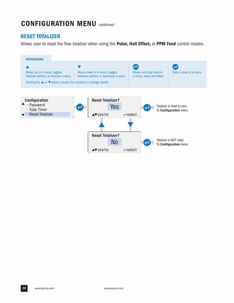
RESET TOTALIZERAllows user to reset the flow totalizer when using the Pulse, Hall Effect, or PPM Feed control modes.
Configuration- Password- Tube Timer- Reset Totalizer
Totalizer is reset to zero. To Configuration menu
Reset Totalizer?
Yesyes/no select
Totalizer is NOT reset. To Configuration menu
Reset Totalizer?
Noyes/no select
Sets a value in a menu
NAVIGATION
Moves one step back ina menu, when permitted
Moves up in a menu, togglesbetween options, or increase a value
Moves down in a menu, togglesbetween options, or decreases a value
Holding the or button causes the numbers to change rapidly.
Delay to activate
_ _ 0 Second(s)
US and Canada 800.683.2378, International 904.641.1666 21
Leak detect alarmnot enabled. ToConfigurationmenu
CONFIGURATION MENU continued
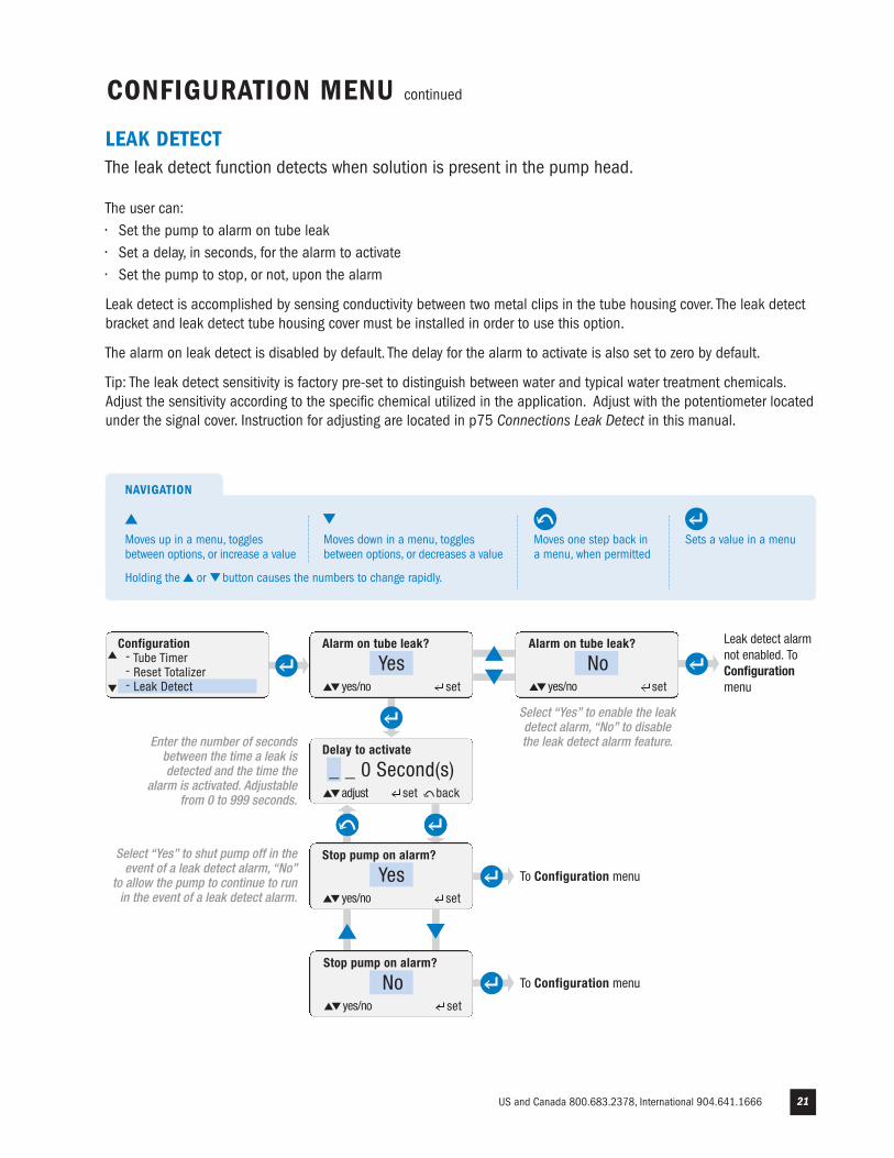
Configuration- Tube Timer- Reset Totalizer- Leak Detect
Alarm on tube leak?
Yesyes/no set
Alarm on tube leak?
Noyes/no set
Stop pump on alarm?
Yesyes/no set
adjust set back
Stop pump on alarm?
Noyes/no set
To Configuration menu
To Configuration menu
Select “Yes” to enable the leakdetect alarm, “No” to disablethe leak detect alarm feature.Enter the number of seconds
between the time a leak isdetected and the time the
alarm is activated. Adjustablefrom 0 to 999 seconds.
Select “Yes” to shut pump off in theevent of a leak detect alarm, “No”
to allow the pump to continue to runin the event of a leak detect alarm.
LEAK DETECTThe leak detect function detects when solution is present in the pump head.
The user can:• Set the pump to alarm on tube leak• Set a delay, in seconds, for the alarm to activate• Set the pump to stop, or not, upon the alarm
Leak detect is accomplished by sensing conductivity between two metal clips in the tube housing cover. The leak detectbracket and leak detect tube housing cover must be installed in order to use this option.
The alarm on leak detect is disabled by default. The delay for the alarm to activate is also set to zero by default.
Tip: The leak detect sensitivity is factory pre-set to distinguish between water and typical water treatment chemicals.Adjust the sensitivity according to the specific chemical utilized in the application. Adjust with the potentiometer locatedunder the signal cover. Instruction for adjusting are located in p75 Connections Leak Detect in this manual.
Sets a value in a menu
NAVIGATION
Moves one step back ina menu, when permitted
Moves up in a menu, togglesbetween options, or increase a value
Moves down in a menu, togglesbetween options, or decreases a value
Holding the or button causes the numbers to change rapidly.
www.stenner.com22
CONFIGURATION MENU continued
OUTPUTS (RELAY) page 1 of 4
Allows user to configure the three internal relays for output indication from the pump to a controlsystem, another pump or miscellaneous receptacle.
• The S Series Pump has three dry contact relays. The relays can be programmed Normally Open (NO) or Normally Closed (NC) to suit the specific application.
• The relays are rated for 24VDC @ 50mA max.
• Each relay can be individually set to activate on any of the following conditions. The relay will activate any time one of the selected conditions exists. The conditions are listed below:
OUTPUTS – ALL MODES OF OPERATION
Leak Detect: Activates relay if pump alarms on leak detect.
Repeat Pulse: Activates the relay when the pump receives a dry contact input signal. The Repeat Pulse feature is used to repeat an incoming signal and relay it to another pump or controller.
Run: Activates the relay whenever the pump is running.
Transfer – Activates the relay in the event the pump is shut down due to a pump alarm condition.– If the primary pump shuts down due to a pump alarm (which can be a drive fault or tube leak detect) or loss of power, the relay will open. The open relay will allow the backup pump to immediately start running.
– When a drive fault or loss of power occurs, the pump will shut down automatically. The user must choose to shut down the pump when the leak detect alarm is programmed and enabled.
– Transfer is intended to be programmed as Normally Closed (NC) and the output used as the input to the Standby function of a backup pump. The backup pump is programmed in the same mode as the primary pump and powered off of a separate circuit.
– When programming a relay for the Transfer function, DO NOT select any other condition for the relay to be activated.
Drive Fault: Activates the relay if the pump shuts down due to a drive fault error.
Standby: Activates the relay if the pump goes into Standby.
Off: Activates the relay if the pump is turned OFF from the control panel.
Mode Change: Activates the external alarm if the pump’s mode of operation is changed.– Only one mode of operation can be selected. The relay must only be programmed for the current mode of operation.
OUTPUTS – SPECIFIC MODES OF OPERATION
Low Signal – 4-20mA or 0-10VDC– Activates the relay if the pump alarms on a Low Signal. The Low Signal alarm is non-latching and will clear itself if the signal returns back to its normal range.
High Signal - 4-20mA or 0-10VDC– Activates the relay if the pump alarms on a High Signal. The High Signal alarm is non-latching and will clear itself if the signal returns back to its normal range.
Low Flow – Hall Effect– Activates the relay if the pump alarms on a low process flow.
High Flow – Hall Effect or PPM Feed– Activates the relay if the pump alarms on a high process flow.
Signal Overrun - Pulse– Activates the relay if the pump receives input signals during a run cycle.
US and Canada 800.683.2378, International 904.641.1666 23
Continue to page 3
CONFIGURATION MENU continued
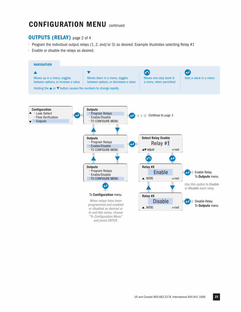
OUTPUTS (RELAY) page 2 of 4
• Program the individual output relays (1, 2, and/or 3) as desired. Example illustrates selecting Relay #1• Enable or disable the relays as desired.
Configuration- Leak Detect- Flow Verification- Outputs
Select Relay Enable
Relay #1adjust set
Relay #X
Enable Enable Relay. To Outputs menu. N/DIS set
Outputs- Program Relays- Enable/Disable- TO CONFIGURE MENU
Outputs- Program Relays- Enable/Disable- TO CONFIGURE MENU
Outputs- Program Relays- Enable/Disable- TO CONFIGURE MENU
To Configuration menu Relay #X
Disable Disable Relay. To Outputs menu. N/DIS set
Use this option to Enableor Disable each relay.
When relays have beenprogrammed and enabledor disabled as desired or to exit this menu, choose “To Configuration Menu”
and press ENTER.
Sets a value in a menu
NAVIGATION
Moves one step back ina menu, when permitted
Moves up in a menu, togglesbetween options, or increase a value
Moves down in a menu, togglesbetween options, or decreases a value
Holding the or button causes the numbers to change rapidly.
Any Control Mode
Pulse
Any Control Mode
Hall Effect or PPM Feed
www.stenner.com24
Continue to page 4
CONFIGURATION MENU continued
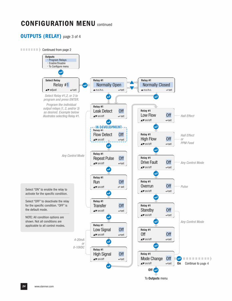
OUTPUTS (RELAY) page 3 of 4
Select Relay
Relay #1
Relay #1
Leak Detect Off
Relay #X
Leak Detect Offon/off set
Relay #1
set
Relay #1
set
Relay #X
Leak Detect Offon/off set
Relay #1
set
Relay #1
Flow Detect Offset
Relay #X
Leak Detect Offon/off set
Relay #1
set
Relay #1
set
Relay #X
Leak Detect Offon/off set
Relay #1
set
Relay #1
set
Relay #1
set
Relay #X
Leak Detect Offon/off set
Relay #1
set
Relay #1
set
Relay #X
Leak Detect Offon/off set
Relay #1
set
Repeat Pulse Off
Low Signal Off
High Flow Off
Standby OffTransfer Off
Low Flow Off
Overrun Off
Mode Change Off
Run Off
High Signal Off
Drive Fault Off
To Outputs menu
Relay #X
Leak Detect Offon/off set
Relay #1
set
Off Off
Continued from page 2
adjust set
on/off set
on/off
on/off
on/off
on/off
on/off
on/off
on/off
on/off
on/off
on/off
on/off
on/off
on/off
Off
On
Select Relay #1,2, or 3 toprogram and press ENTER.
Program the individualoutput relays (1, 2, and/or 3)as desired. Example belowillustrates selecting Relay #1.
Relay #1
Normally Openn.o./n.c. set
Relay #1
Normally Closedn.o./n.c. set
Outputs- Program Relays- Enable/Disable- To Configure menu
Select “ON” to enable the relay toactivate for the specific condition.
Select “OFF” to deactivate the relayfor the specific condition. “OFF” isthe default mode.
NOTE: All condition options areshown. Not all conditions areapplicable to all control modes.
Any Control Mode
Hall Effect
4-20mAor
0-10VDC
US and Canada 800.683.2378, International 904.641.1666 25
CONFIGURATION MENU continued
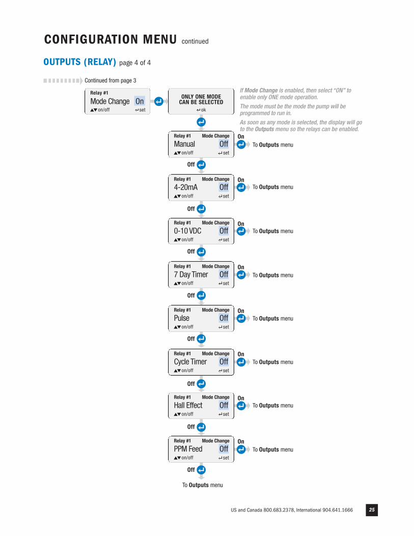
OUTPUTS (RELAY) page 4 of 4
ok
ONLY ONE MODE CAN BE SELECTED
Relay #X
Leak Detect Offon/off set
Relay #1
Manual OffMode Change
Relay #X
Leak Detect Offon/off set
Relay #1
set
4-20mA OffMode Change
Relay #X
Leak Detect Offon/off set
Relay #1
set
0-10 VDC OffMode Change
on/off set
on/off
on/off
Relay #X
Leak Detect Offon/off set
Relay #1
set
7 Day Timer OffMode Change
on/off
Relay #X
Leak Detect Offon/off set
Relay #1
set
Pulse OffMode Change
on/off
Relay #X
Leak Detect Offon/off set
Relay #1
set
Cycle Timer OffMode Change
on/off
Relay #X
Leak Detect Offon/off set
Relay #1
set
Hall Effect OffMode Change
on/off
Relay #X
Leak Detect Offon/off set
Relay #1
set
PPM Feed OffMode Change
on/off
To Outputs menu
Off
Off
Off
Off
Off
Off
Off
Off
On
On
On
On
On
On
On
On
To Outputs menu
To Outputs menu
To Outputs menu
To Outputs menu
To Outputs menu
To Outputs menu
To Outputs menu
To Outputs menu
If Mode Change is enabled, then select “ON” toenable only ONE mode operation.
The mode must be the mode the pump will beprogrammed to run in.
As soon as any mode is selected, the display will goto the Outputs menu so the relays can be enabled.
Relay #1
set
Mode Change Onon/off
Continued from page 3
www.stenner.com26
CONFIGURATION MENU continued
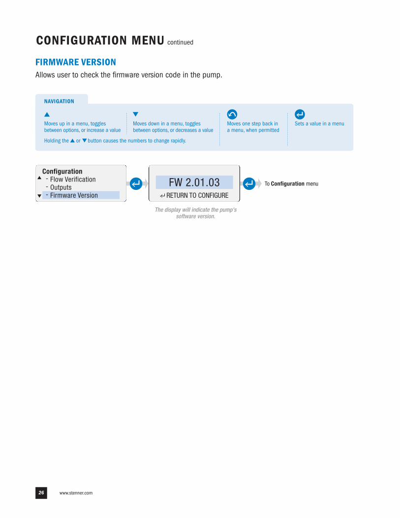
FIRMWARE VERSIONAllows user to check the firmware version code in the pump.
Configuration- Flow Verification- Outputs- Firmware Version
FW 2.01.03RETURN TO CONFIGURE
To Configuration menu
Sets a value in a menu
NAVIGATION
Moves one step back ina menu, when permitted
Moves up in a menu, togglesbetween options, or increase a value
Moves down in a menu, togglesbetween options, or decreases a value
Holding the or button causes the numbers to change rapidly.
The display will indicate the pump'ssoftware version.
US and Canada 800.683.2378, International 904.641.1666 27
CONFIGURATION MENU continued
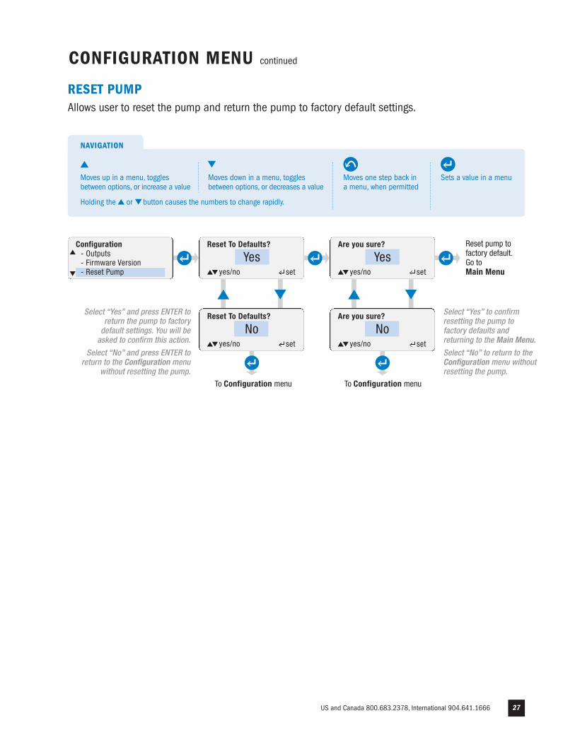
RESET PUMPAllows user to reset the pump and return the pump to factory default settings.
To Configuration menu
Reset To Defaults?Configuration- Outputs- Firmware Version- Reset Pump
Yesyes/no set
Are you sure?
Yesyes/no set
Reset To Defaults?
Noyes/no set
Are you sure?
Noyes/no set
Reset pump tofactory default.Go to Main Menu
Select “Yes” and press ENTER toreturn the pump to factorydefault settings. You will beasked to confirm this action.
Select “No” and press ENTER toreturn to the Configuration menu
without resetting the pump.
Select “Yes” to confirmresetting the pump tofactory defaults andreturning to the Main Menu.
Select “No” to return to theConfiguration menu withoutresetting the pump.
To Configuration menu
Sets a value in a menu
NAVIGATION
Moves one step back ina menu, when permitted
Moves up in a menu, togglesbetween options, or increase a value
Moves down in a menu, togglesbetween options, or decreases a value
Holding the or button causes the numbers to change rapidly.
www.stenner.com28
CONFIGURATION MENU continued
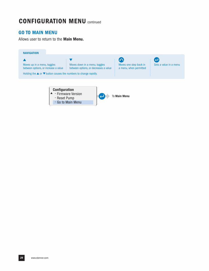
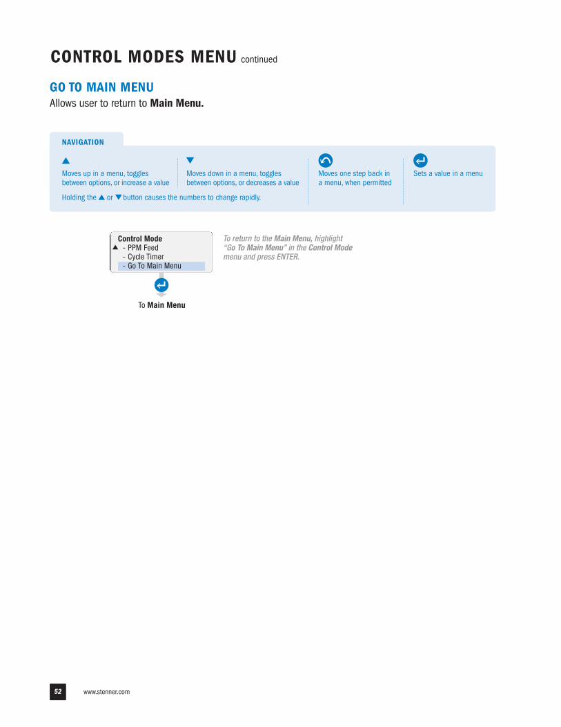
GO TO MAIN MENUAllows user to return to the Main Menu.
Configuration- Firmware Version- Reset Pump- Go to Main Menu
To Main Menu
Sets a value in a menu
NAVIGATION
Moves one step back ina menu, when permitted
Moves up in a menu, togglesbetween options, or increase a value
Moves down in a menu, togglesbetween options, or decreases a value
Holding the or button causes the numbers to change rapidly.
US and Canada 800.683.2378, International 904.641.1666 29
CONTROL MODES MENU
Main Menu- Configuration- Control Mode- Run Pump
Control Mode- Manual- 4-20mA- 0-10 VDC
Control Mode- Manual- 4-20mA- 0-10 VDC
Control Mode- Manual- 4-20mA- 0-10 VDC
Control Mode- 4-20mA- 0-10 VDC- Pulse
Control Mode- 0-10 VDC- Pulse- Hall Effect
Control Mode- Pulse- Hall Effect- 7 Day Timer
Control Mode- Hall Effect- 7 Day Timer- PPM Feed
Control Mode- 7 Day Timer- PPM Feed- Cycle Timer
Control Mode- PPM Feed- Cycle Timer- Go to Main Menu
To Manual sub menu
Sets a value in a menu
NAVIGATION
Moves one step back ina menu, when permitted
Moves up in a menu, togglesbetween options, or increase a value
Moves down in a menu, togglesbetween options, or decreases a value
Holding the or button causes the numbers to change rapidly.
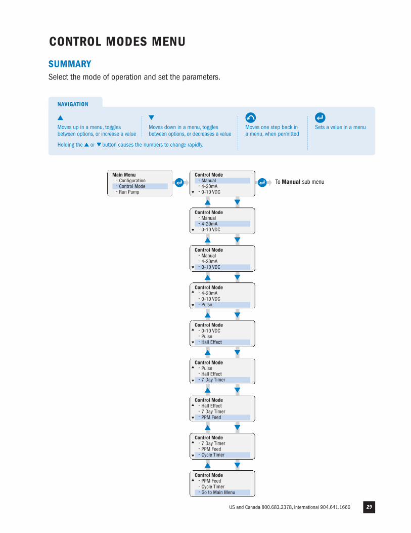
SUMMARYSelect the mode of operation and set the parameters.
www.stenner.com30
CONTROL MODES MENU continued
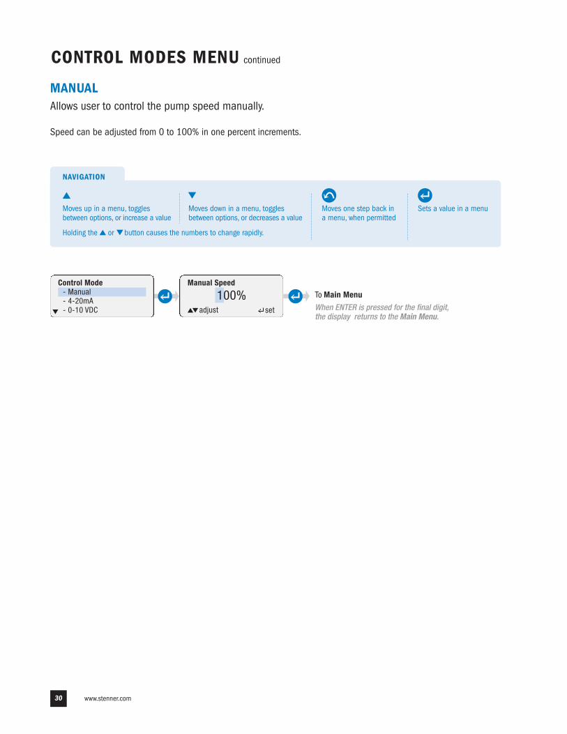
MANUALAllows user to control the pump speed manually.
Speed can be adjusted from 0 to 100% in one percent increments.
To Main Menu
When ENTER is pressed for the final digit,the display returns to the Main Menu.
Manual SpeedControl Mode- Manual- 4-20mA- 0-10 VDC
100%adjust set
Sets a value in a menu
NAVIGATION
Moves one step back ina menu, when permitted
Moves up in a menu, togglesbetween options, or increase a value
Moves down in a menu, togglesbetween options, or decreases a value
Holding the or button causes the numbers to change rapidly.
US and Canada 800.683.2378, International 904.641.1666 31
4-20mA page 1 of 3
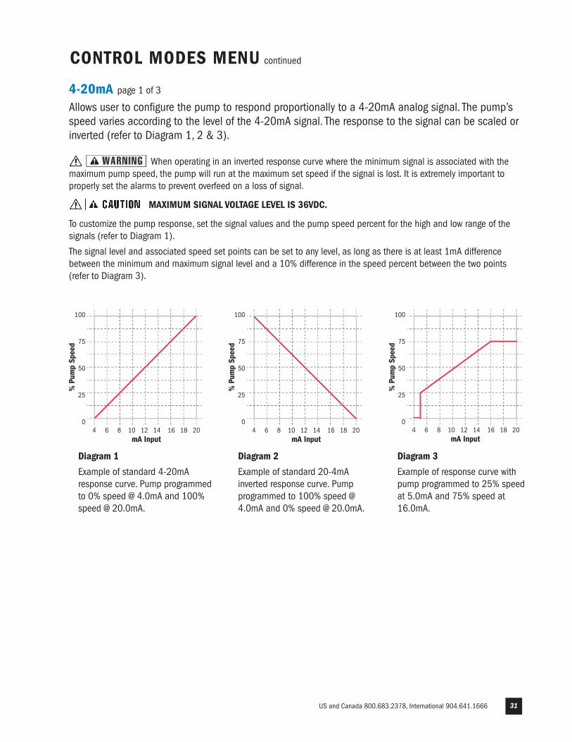
Allows user to configure the pump to respond proportionally to a 4-20mA analog signal. The pump’sspeed varies according to the level of the 4-20mA signal. The response to the signal can be scaled orinverted (refer to Diagram 1, 2 & 3).
When operating in an inverted response curve where the minimum signal is associated with themaximum pump speed, the pump will run at the maximum set speed if the signal is lost. It is extremely important toproperly set the alarms to prevent overfeed on a loss of signal.
MAXIMUM SIGNAL VOLTAGE LEVEL IS 36VDC.
To customize the pump response, set the signal values and the pump speed percent for the high and low range of thesignals (refer to Diagram 1).
The signal level and associated speed set points can be set to any level, as long as there is at least 1mA differencebetween the minimum and maximum signal level and a 10% difference in the speed percent between the two points(refer to Diagram 3).
CONTROL MODES MENU continued
4 6 8 10 12 14 16 18 20mA Input
100
75
50
25
0
% P
ump
Spee
d
4 6 8 10 12 14 16 18 20mA Input
100
75
50
25
0
% P
ump
Spee
d
4 6 8 10 12 14 16 18 20mA Input
100
75
50
25
0
% P
ump
Spee
d
Diagram 1
Example of standard 4-20mAresponse curve. Pump programmedto 0% speed @ 4.0mA and 100%speed @ 20.0mA.
Diagram 3
Example of response curve withpump programmed to 25% speedat 5.0mA and 75% speed at16.0mA.
Diagram 2
Example of standard 20-4mAinverted response curve. Pumpprogrammed to 100% speed @4.0mA and 0% speed @ 20.0mA.
Minimum Signal
_4.0 mAadjust set
To 4-20mA menu
www.stenner.com32
CONTROL MODES MENU continued
4-20mA page 2 of 3
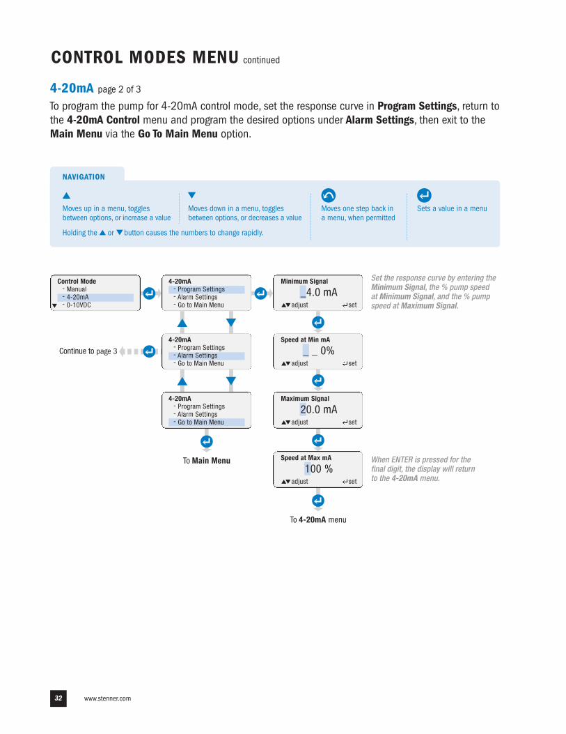
To program the pump for 4-20mA control mode, set the response curve in Program Settings, return tothe 4-20mA Control menu and program the desired options under Alarm Settings, then exit to theMain Menu via the Go To Main Menu option.
Control Mode- Manual- 4-20mA- 0-10VDC
4-20mA- Program Settings- Alarm Settings- Go to Main Menu
4-20mA- Program Settings- Alarm Settings- Go to Main Menu
4-20mA- Program Settings- Alarm Settings- Go to Main Menu
To Main Menu
Speed at Min mA
_ _ 0%
Maximum Signal
20.0 mA
Speed at Max mA
100 %
Continue to page 3
When ENTER is pressed for thefinal digit, the display will returnto the 4-20mA menu.
adjust set
adjust set
adjust set
Set the response curve by entering theMinimum Signal, the % pump speedat Minimum Signal, and the % pumpspeed at Maximum Signal.
Sets a value in a menu
NAVIGATION
Moves one step back ina menu, when permitted
Moves up in a menu, togglesbetween options, or increase a value
Moves down in a menu, togglesbetween options, or decreases a value
Holding the or button causes the numbers to change rapidly.
US and Canada 800.683.2378, International 904.641.1666 33
CONTROL MODES MENU continued
4-20mA page 3 of 3
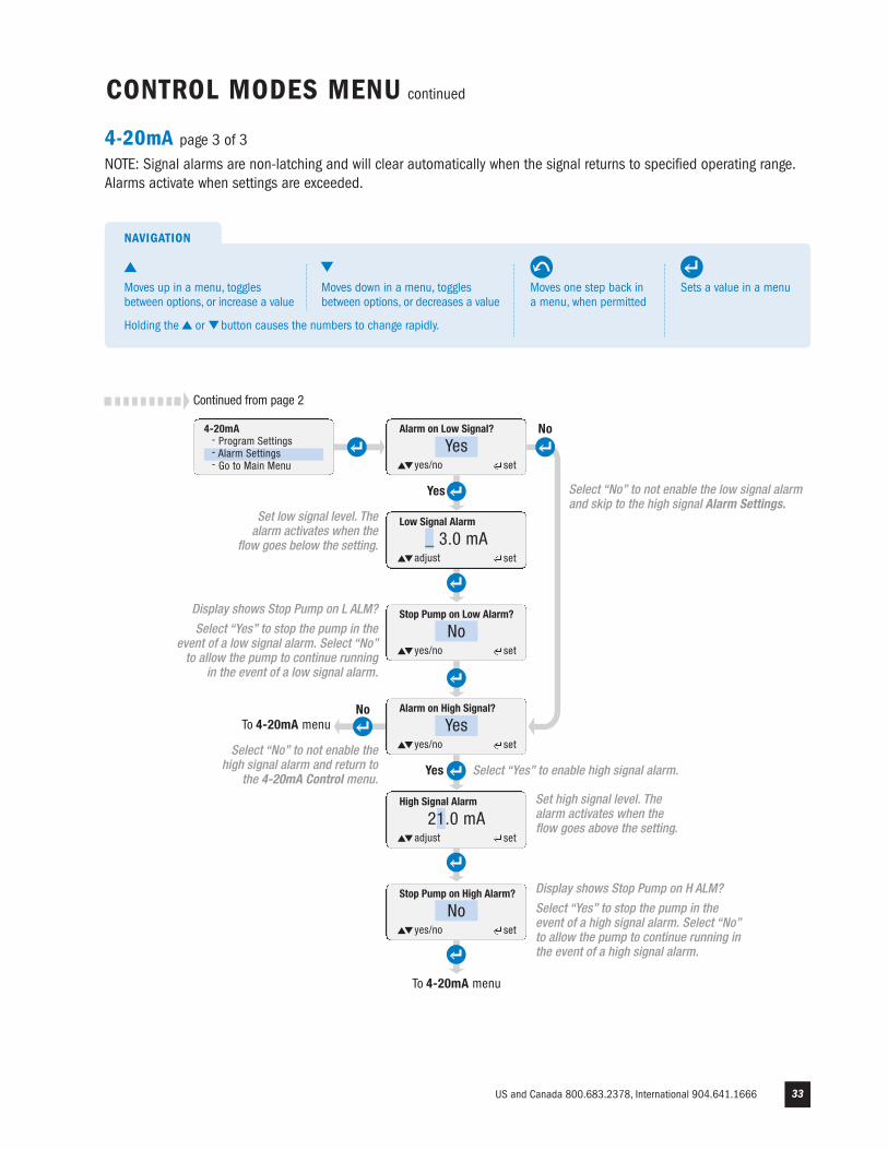
NOTE: Signal alarms are non-latching and will clear automatically when the signal returns to specified operating range.Alarms activate when settings are exceeded.
To 4-20mA menu
Yes
No
High Signal Alarm
21.0 mA
Stop Pump on High Alarm?
Noyes/no set
Alarm on Low Signal?
Continued from page 2
yes/no set
Yes
No
Low Signal Alarm
_ 3.0 mA
Stop Pump on Low Alarm?
Noyes/no set
Alarm on High Signal?
yes/no set
To 4-20mA menu
Set high signal level. Thealarm activates when theflow goes above the setting.
Display shows Stop Pump on L ALM?
Select “Yes” to stop the pump in theevent of a low signal alarm. Select “No”to allow the pump to continue running
in the event of a low signal alarm.
adjust set
adjust set
4-20mA- Program Settings- Alarm Settings- Go to Main Menu
Select “Yes” to enable high signal alarm.
Select “No” to not enable the low signal alarmand skip to the high signal Alarm Settings.
Set low signal level. Thealarm activates when the
flow goes below the setting.
Display shows Stop Pump on H ALM?
Select “Yes” to stop the pump in theevent of a high signal alarm. Select “No”to allow the pump to continue running inthe event of a high signal alarm.
Select “No” to not enable thehigh signal alarm and return to
the 4-20mA Control menu.
Sets a value in a menu
NAVIGATION
Moves one step back ina menu, when permitted
Moves up in a menu, togglesbetween options, or increase a value
Moves down in a menu, togglesbetween options, or decreases a value
Holding the or button causes the numbers to change rapidly.
Yes
Yes
www.stenner.com34
0-10VDC page 1 of 3
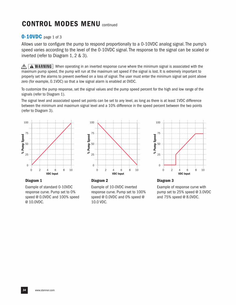
Allows user to configure the pump to respond proportionally to a 0-10VDC analog signal. The pump’sspeed varies according to the level of the 0-10VDC signal. The response to the signal can be scaled orinverted (refer to Diagram 1, 2 & 3).
When operating in an inverted response curve where the minimum signal is associated with themaximum pump speed, the pump will run at the maximum set speed if the signal is lost. It is extremely important toproperly set the alarms to prevent overfeed on a loss of signal. The user must enter the minimum signal set point abovezero (for example, 0.1VDC) so that a low signal alarm is enabled at 0VDC.
To customize the pump response, set the signal values and the pump speed percent for the high and low range of thesignals (refer to Diagram 1).
The signal level and associated speed set points can be set to any level, as long as there is at least 1VDC differencebetween the minimum and maximum signal level and a 10% difference in the speed percent between the two points(refer to Diagram 3).
CONTROL MODES MENU continued
Diagram 1
Example of standard 0-10VDCresponse curve. Pump set to 0%speed @ 0.0VDC and 100% speed@ 10.0VDC.
Diagram 3
Example of response curve withpump set to 25% speed @ 3.0VDCand 75% speed @ 8.0VDC.
Diagram 2
Example of 10-0VDC invertedresponse curve. Pump set to 100%speed @ 0.0VDC and 0% speed @10.0 VDC.
0 2 4 6 8 10VDC Input
100
75
50
25
0
% P
ump
Spee
d
0 2 4 6 8 10VDC Input
100
75
50
25
0
% P
ump
Spee
d
0 2 4 6 8 10VDC Input
100
75
50
25
0
% P
ump
Spee
d
35
CONTROL MODES MENU continued
0-10VDC page 2 of 3
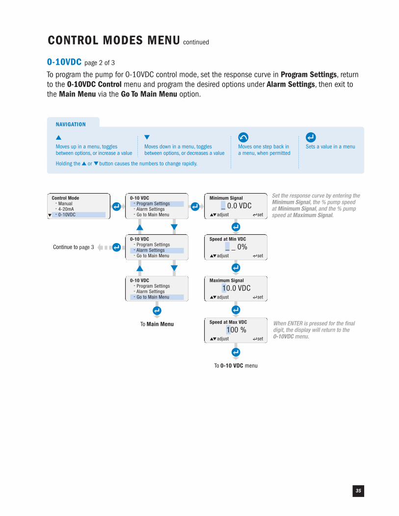
To program the pump for 0-10VDC control mode, set the response curve in Program Settings, returnto the 0-10VDC Control menu and program the desired options under Alarm Settings, then exit tothe Main Menu via the Go To Main Menu option.
Control Mode- Manual- 4-20mA- 0-10VDC
0-10 VDC- Program Settings- Alarm Settings- Go to Main Menu
0-10 VDC- Program Settings- Alarm Settings- Go to Main Menu
0-10 VDC- Program Settings- Alarm Settings- Go to Main Menu
To Main Menu
Continue to page 3
Minimum Signal
_ 0.0 VDCadjust set
To 0-10 VDC menu
Speed at Min VDC
_ _ 0%
Maximum Signal
10.0 VDC
Speed at Max VDC
100 %When ENTER is pressed for the finaldigit, the display will return to the 0-10VDC menu.
adjust set
adjust set
adjust set
Set the response curve by entering theMinimum Signal, the % pump speedat Minimum Signal, and the % pumpspeed at Maximum Signal.
Sets a value in a menu
NAVIGATION
Moves one step back ina menu, when permitted
Moves up in a menu, togglesbetween options, or increase a value
Moves down in a menu, togglesbetween options, or decreases a value
Holding the or button causes the numbers to change rapidly.
www.stenner.com36
CONTROL MODES MENU continued
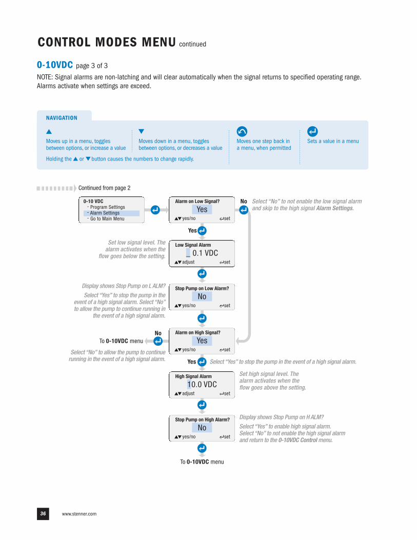
0-10VDC page 3 of 3
NOTE: Signal alarms are non-latching and will clear automatically when the signal returns to specified operating range.Alarms activate when settings are exceed.
To 0-10VDC menu
Yes
No
High Signal Alarm
10.0 VDC
Stop Pump on High Alarm?
Noyes/no set
Alarm on Low Signal?
Continued from page 2
yes/no set
Yes
No
Low Signal Alarm
_ 0.1 VDC
Stop Pump on Low Alarm?
Noyes/no set
Alarm on High Signal?
yes/no set
To 0-10VDC menu
Set high signal level. Thealarm activates when theflow goes above the setting.
Display shows Stop Pump on L ALM?
Select “Yes” to stop the pump in theevent of a high signal alarm. Select “No”to allow the pump to continue running in
the event of a high signal alarm.
adjust set
adjust set
0-10 VDC- Program Settings- Alarm Settings- Go to Main Menu
Select “Yes” to stop the pump in the event of a high signal alarm.
Select “No” to not enable the low signal alarmand skip to the high signal Alarm Settings.
Set low signal level. Thealarm activates when the
flow goes below the setting.
Display shows Stop Pump on H ALM?
Select “Yes” to enable high signal alarm.Select “No” to not enable the high signal alarmand return to the 0-10VDC Control menu.
Select “No” to allow the pump to continuerunning in the event of a high signal alarm.
Sets a value in a menu
NAVIGATION
Moves one step back ina menu, when permitted
Moves up in a menu, togglesbetween options, or increase a value
Moves down in a menu, togglesbetween options, or decreases a value
Holding the or button causes the numbers to change rapidly.
Yes
Yes
US and Canada 800.683.2378, International 904.641.1666 37
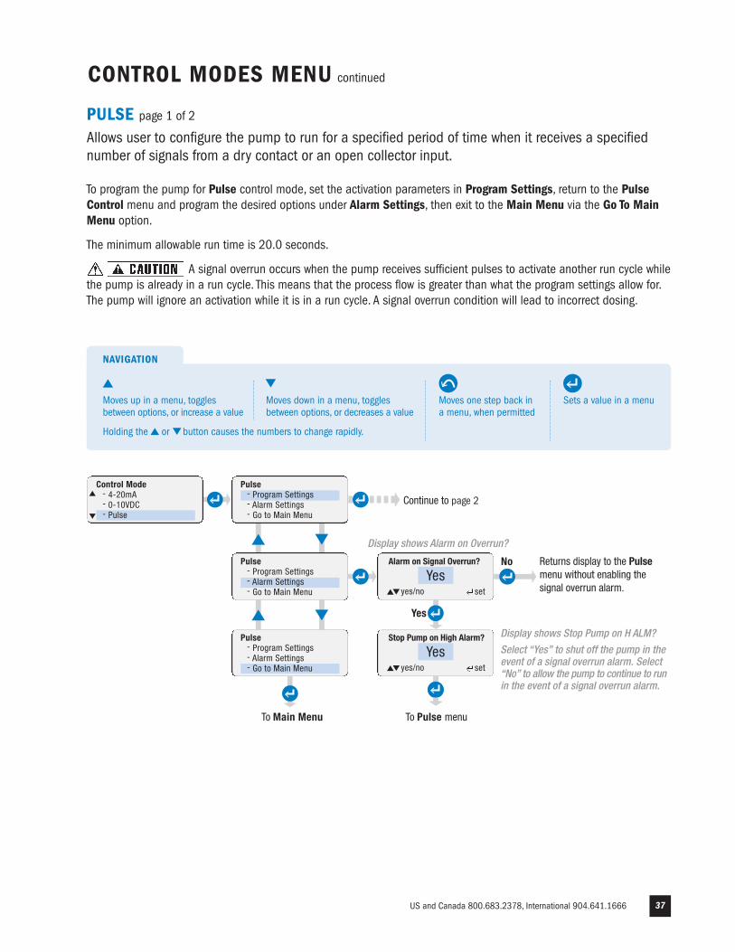
No Returns display to the Pulsemenu without enabling thesignal overrun alarm.
PULSE page 1 of 2
Allows user to configure the pump to run for a specified period of time when it receives a specifiednumber of signals from a dry contact or an open collector input.
To program the pump for Pulse control mode, set the activation parameters in Program Settings, return to the PulseControl menu and program the desired options under Alarm Settings, then exit to the Main Menu via the Go To MainMenu option.
The minimum allowable run time is 20.0 seconds.
A signal overrun occurs when the pump receives sufficient pulses to activate another run cycle whilethe pump is already in a run cycle. This means that the process flow is greater than what the program settings allow for.The pump will ignore an activation while it is in a run cycle. A signal overrun condition will lead to incorrect dosing.
CONTROL MODES MENU continued
Pulse - Program Settings- Alarm Settings- Go to Main Menu
Pulse - Program Settings- Alarm Settings- Go to Main Menu
To Main Menu
Display shows Stop Pump on H ALM?
Select “Yes” to shut off the pump in theevent of a signal overrun alarm. Select“No” to allow the pump to continue to runin the event of a signal overrun alarm.
Pulse - Program Settings- Alarm Settings- Go to Main Menu
Alarm on Signal Overrun?
Yesyes/no set
Yes
Stop Pump on High Alarm?
Yesyes/no set
To Pulse menu
Continue to page 2
Control Mode- 4-20mA- 0-10VDC- Pulse
Sets a value in a menu
NAVIGATION
Moves one step back ina menu, when permitted
Moves up in a menu, togglesbetween options, or increase a value
Moves down in a menu, togglesbetween options, or decreases a value
Holding the or button causes the numbers to change rapidly.
Display shows Alarm on Overrun?
www.stenner.com38
CONTROL MODES MENU continued
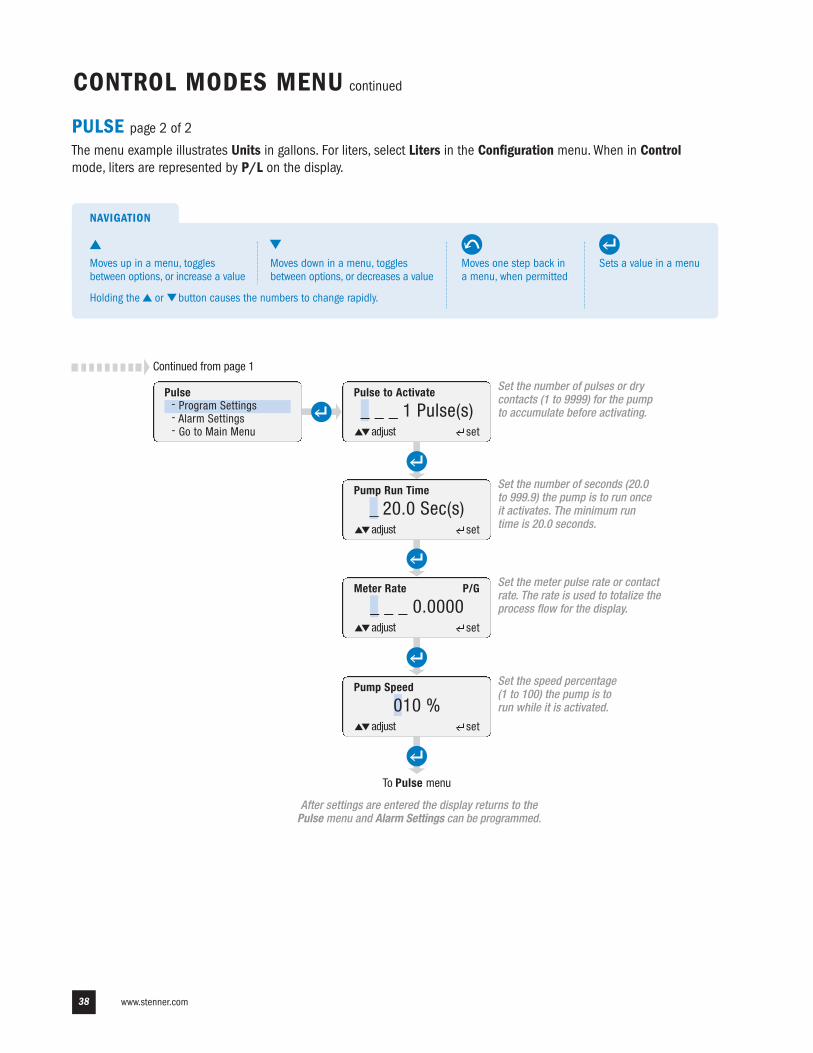
PULSE page 2 of 2
The menu example illustrates Units in gallons. For liters, select Liters in the Configuration menu. When in Controlmode, liters are represented by P/L on the display.
Pulse to Activate
_ _ _ 1 Pulse(s)adjust set
set
Set the number of pulses or drycontacts (1 to 9999) for the pumpto accumulate before activating.
Pump Run Time
_ 20.0 Sec(s)adjust set
Meter Rate
_ _ _ 0.0000adjust set
P/G
Pump Speed
010 %adjust set
To Pulse menu
Set the number of seconds (20.0to 999.9) the pump is to run onceit activates. The minimum runtime is 20.0 seconds.
Set the meter pulse rate or contactrate. The rate is used to totalize theprocess flow for the display.
Set the speed percentage(1 to 100) the pump is torun while it is activated.
After settings are entered the display returns to thePulse menu and Alarm Settings can be programmed.
Pulse - Program Settings- Alarm Settings- Go to Main Menu
Continued from page 1
Sets a value in a menu
NAVIGATION
Moves one step back ina menu, when permitted
Moves up in a menu, togglesbetween options, or increase a value
Moves down in a menu, togglesbetween options, or decreases a value
Holding the or button causes the numbers to change rapidly.
US and Canada 800.683.2378, International 904.641.1666 39
CONTROL MODES MENU continued
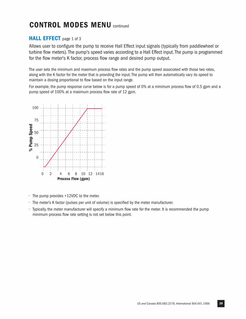
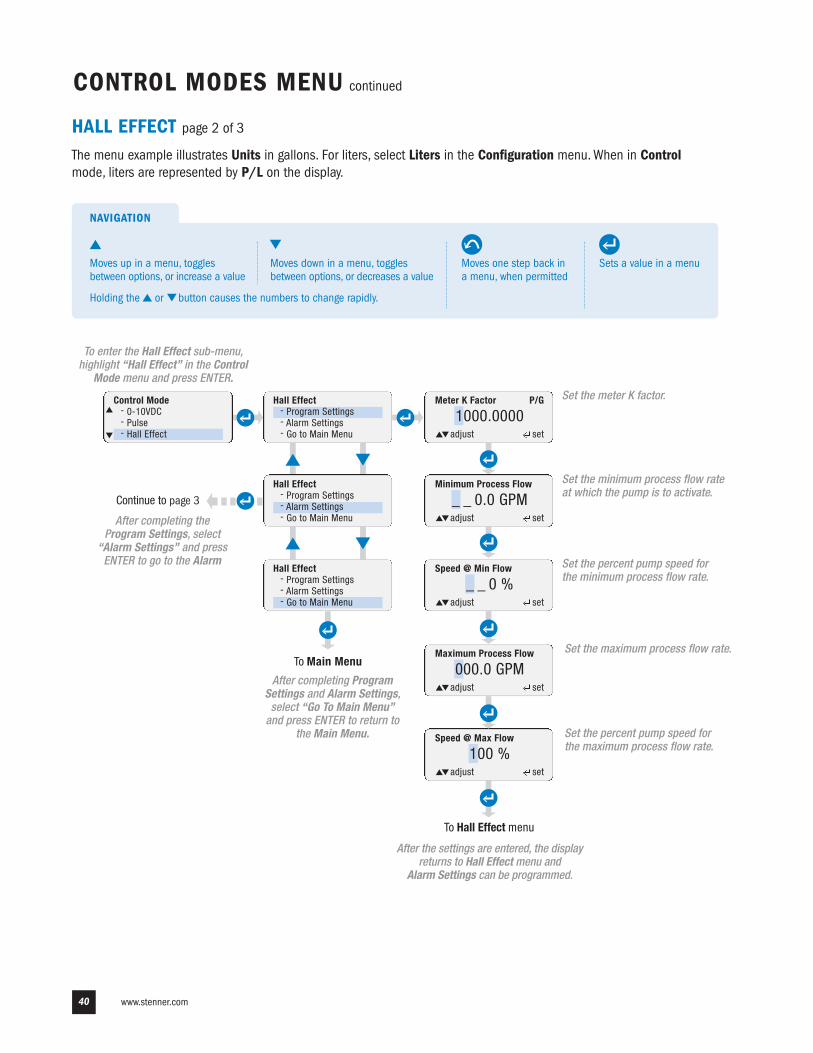
HALL EFFECT page 1 of 3
Allows user to configure the pump to receive Hall Effect input signals (typically from paddlewheel orturbine flow meters). The pump's speed varies according to a Hall Effect input. The pump is programmedfor the flow meter's K factor, process flow range and desired pump output.
The user sets the minimum and maximum process flow rates and the pump speed associated with those two rates,along with the K factor for the meter that is providing the input. The pump will then automatically vary its speed tomaintain a dosing proportional to flow based on the input range.
For example, the pump response curve below is for a pump speed of 0% at a minimum process flow of 0.5 gpm and apump speed of 100% at a maximum process flow rate of 12 gpm.
0 2 4 6 8 10 12 1416Process Flow (gpm)
100
75
50
25
0
% P
ump
Spee
d
• The pump provides +12VDC to the meter.
• The meter’s K factor (pulses per unit of volume) is specified by the meter manufacturer.
• Typically, the meter manufacturer will specify a minimum flow rate for the meter. It is recommended the pump minimum process flow rate setting is not set below this point.
www.stenner.com40
Speed @ Max Flow
100 %adjust set
CONTROL MODES MENU continued
HALL EFFECT page 2 of 3
The menu example illustrates Units in gallons. For liters, select Liters in the Configuration menu. When in Controlmode, liters are represented by P/L on the display.
Control Mode- 0-10VDC- Pulse- Hall Effect
Hall Effect- Program Settings- Alarm Settings- Go to Main Menu
Hall Effect- Program Settings- Alarm Settings- Go to Main Menu
Hall Effect- Program Settings- Alarm Settings- Go to Main Menu
To Main Menu
Continue to page 3
Meter K Factor
1000.0000adjust set
To Hall Effect menu
Minimum Process Flow
_ _ 0.0 GPM
Speed @ Min Flow
_ _ 0 %
Maximum Process Flow
000.0 GPMSet the maximum process flow rate.
adjust set
adjust set
adjust set
Set the meter K factor.P/G
Set the minimum process flow rateat which the pump is to activate.
Set the percent pump speed forthe minimum process flow rate.
Set the percent pump speed forthe maximum process flow rate.
After the settings are entered, the displayreturns to Hall Effect menu and
Alarm Settings can be programmed.
After completing ProgramSettings and Alarm Settings,select “Go To Main Menu”and press ENTER to return to
the Main Menu.
After completing theProgram Settings, select
“Alarm Settings” and pressENTER to go to the Alarm
To enter the Hall Effect sub-menu,highlight “Hall Effect” in the Control
Mode menu and press ENTER.
Sets a value in a menu
NAVIGATION
Moves one step back ina menu, when permitted
Moves up in a menu, togglesbetween options, or increase a value
Moves down in a menu, togglesbetween options, or decreases a value
Holding the or button causes the numbers to change rapidly.
US and Canada 800.683.2378, International 904.641.1666 41
CONTROL MODES MENU continued
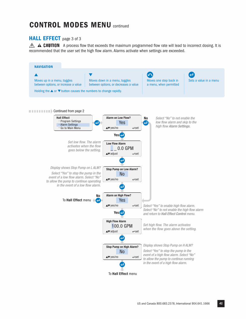
To Hall Effect menu
Yes
No
High Flow Alarm
100.0 GPM
Stop Pump on High Alarm?
Noyes/no set
Alarm on Low Flow?
yes/no set
Yes
No
Low Flow Alarm
_ _ 0.0 GPM
Stop Pump on Low Alarm?
Noyes/no set
Alarm on High Flow?
yes/no set
To Hall Effect menu
Display shows Stop Pump on L ALM?
Select “Yes” to stop the pump in theevent of a low flow alarm. Select “No”
to allow the pump to continue operatingin the event of a low flow alarm.
Set high flow. The alarm activateswhen the flow goes above the setting.
Display shows Stop Pump on H ALM?
Select “Yes” to stop the pump in theevent of a high flow alarm. Select “No”to allow the pump to continue runningin the event of a high flow alarm.
adjust set
adjust set
HALL EFFECT page 3 of 3
A process flow that exceeds the maximum programmed flow rate will lead to incorrect dosing. It isrecommended that the user set the high flow alarm. Alarms activate when settings are exceeded.
Continued from page 2
Hall Effect- Program Settings- Alarm Settings- Go to Main Menu
Select “No” to not enable thelow flow alarm and skip to thehigh flow Alarm Settings.
Set low flow. The alarmactivates when the flowgoes below the setting.
Select “Yes” to enable high flow alarm.Select “No” to not enable the high flow alarmand return to Hall Effect Control menu.
Sets a value in a menu
NAVIGATION
Moves one step back ina menu, when permitted
Moves up in a menu, togglesbetween options, or increase a value
Moves down in a menu, togglesbetween options, or decreases a value
Holding the or button causes the numbers to change rapidly.
Yes
Yes
www.stenner.com42
CONFIGURATION MENU continued
7 DAY TIMER page 1 of 3
Allows user to program the pump to turn on and turn off at specific times and specific days. The pumpoperates with a 24 hour clock format.
• There are 24 independent time events. Each event is individually programmable through timers #01 - #24.
• Each timer can be programmed:- For any combination of days- To run from a minimum of 20 seconds to a maximum of 23 hours, 59 minutes, and 59 seconds- To run at a speed from 1% to 100%
• Each programmed event is contained within 24 hours (from 00:00:00 to 23:59:59). The time for an event cannot exceed 23:59:59.
• By default, all timers are disabled. After programming a timer, it must be enabled in order to run.
• Only programmed timers can be enabled.
• The user can return at any time to the 7 Day Timer menu and individually enable or disable the timers to customize their timer events.
• The pump uses a battery to maintain the clock when power is removed.
• The timer programs entered by the user are stored in non-volatile memory.
US and Canada 800.683.2378, International 904.641.1666 43
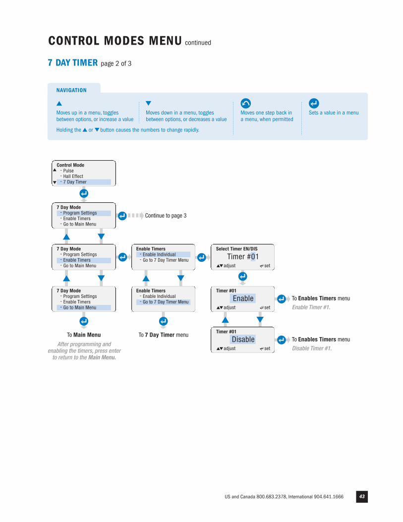
Select Timer EN/DIS
Timer #01adjust set
Enable Timers- Enable Individual- Go to 7 Day Timer Menu
CONTROL MODES MENU continued
7 DAY TIMER page 2 of 3
Control Mode- Pulse- Hall Effect- 7 Day Timer
7 Day Mode- Program Settings- Enable Timers- Go to Main Menu
7 Day Mode- Program Settings- Enable Timers- Go to Main Menu
7 Day Mode - Program Settings- Enable Timers- Go to Main Menu
To Main Menu
After programming andenabling the timers, press enterto return to the Main Menu.
Continue to page 3
Enable Timers- Enable Individual- Go to 7 Day Timer Menu
To 7 Day Timer menu
Timer #01
Enableadjust set
Timer #01
Disableadjust set
To Enables Timers menu
Enable Timer #1.
To Enables Timers menu
Disable Timer #1.
Sets a value in a menu
NAVIGATION
Moves one step back ina menu, when permitted
Moves up in a menu, togglesbetween options, or increase a value
Moves down in a menu, togglesbetween options, or decreases a value
Holding the or button causes the numbers to change rapidly.
www.stenner.com44
Set days to Run
Sunday Offadjust set
7 Day Timer- Program Settings- Enable Timers- Go to Main Menu
CONTROL MODES MENU continued
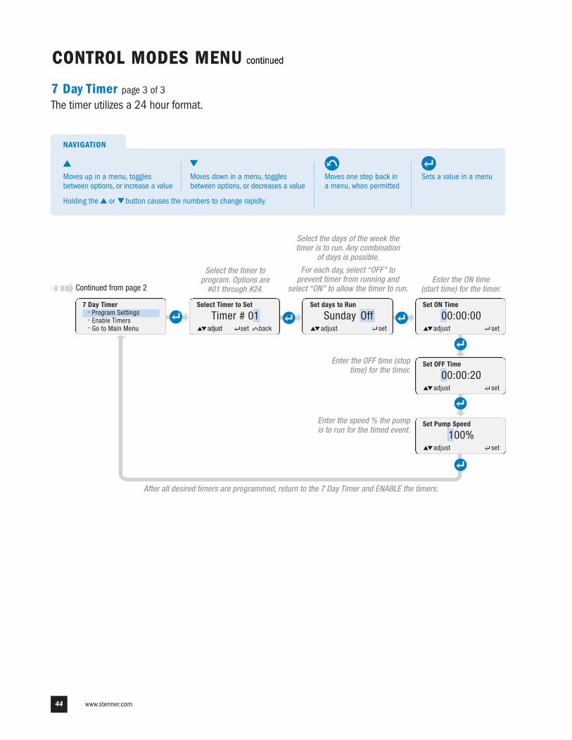
7 Day Timer page 3 of 3
The timer utilizes a 24 hour format.
CONTROL MODES MENU continued
Select the timer toprogram. Options are #01 through #24.
Select the days of the week thetimer is to run. Any combination
of days is possible.
For each day, select “OFF” toprevent timer from running and
select “ON” to allow the timer to run.Enter the ON time
(start time) for the timer.
Set OFF Time
00:00:20adjust set
Set Pump Speed
100%adjust set
Set ON Time
00:00:00adjust set
Enter the OFF time (stoptime) for the timer.
Enter the speed % the pumpis to run for the timed event.
After all desired timers are programmed, return to the 7 Day Timer and ENABLE the timers.
Continued from page 2
Select Timer to Set
Timer # 01adjust set back
Sets a value in a menu
NAVIGATION
Moves one step back ina menu, when permitted
Moves up in a menu, togglesbetween options, or increase a value
Moves down in a menu, togglesbetween options, or decreases a value
Holding the or button causes the numbers to change rapidly.
US and Canada 800.683.2378, International 904.641.1666 45
CONTROL MODES MENU continued
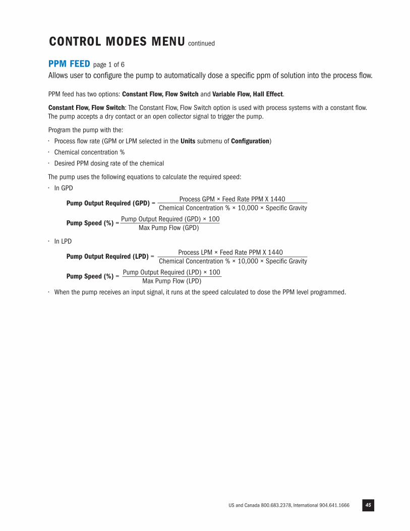
PPM FEED page 1 of 6
Allows user to configure the pump to automatically dose a specific ppm of solution into the process flow.
PPM feed has two options: Constant Flow, Flow Switch and Variable Flow, Hall Effect.
Constant Flow, Flow Switch: The Constant Flow, Flow Switch option is used with process systems with a constant flow.The pump accepts a dry contact or an open collector signal to trigger the pump.
Program the pump with the:
• Process flow rate (GPM or LPM selected in the Units submenu of Configuration)
• Chemical concentration %
• Desired PPM dosing rate of the chemical
The pump uses the following equations to calculate the required speed:
• In GPD
Pump Output Required (GPD) = Process GPM × Feed Rate PPM X 1440 Chemical Concentration % × 10,000 × Specific Gravity
Pump Speed (%) = Pump Output Required (GPD) × 100Max Pump Flow (GPD)
• In LPD
Pump Output Required (LPD) = Process LPM × Feed Rate PPM X 1440 Chemical Concentration % × 10,000 × Specific Gravity
Pump Speed (%) = Pump Output Required (LPD) × 100Max Pump Flow (LPD)
• When the pump receives an input signal, it runs at the speed calculated to dose the PPM level programmed.
www.stenner.com46
Continue topage 3
PPM Feed Constant Flow- Program Settings- Go to PPM Feed Menu
CONTROL MODES MENU continued
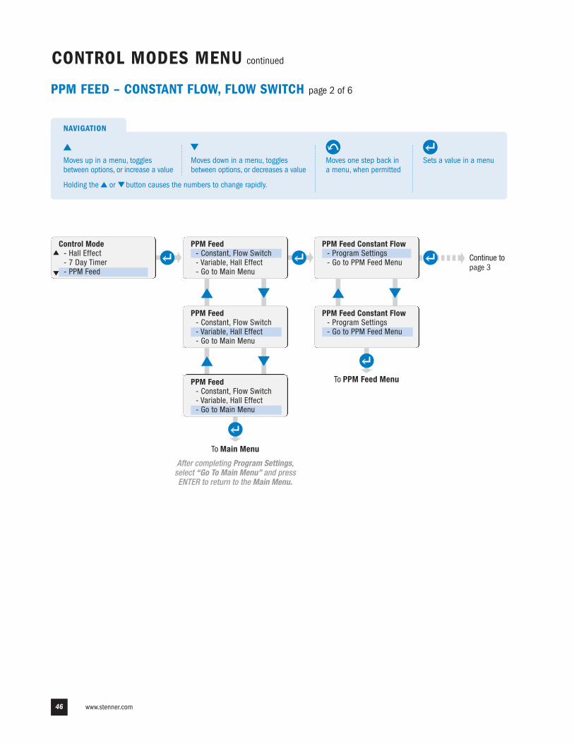
PPM FEED – CONSTANT FLOW, FLOW SWITCH page 2 of 6
PPM Feed- Constant, Flow Switch- Variable, Hall Effect- Go to Main Menu
PPM Feed Constant Flow- Program Settings- Go to PPM Feed Menu
PPM Feed- Constant, Flow Switch- Variable, Hall Effect- Go to Main Menu
PPM Feed- Constant, Flow Switch- Variable, Hall Effect- Go to Main Menu
To Main Menu
After completing Program Settings,select “Go To Main Menu” and pressENTER to return to the Main Menu.
To PPM Feed Menu
Control Mode- Hall Effect- 7 Day Timer- PPM Feed
Sets a value in a menu
NAVIGATION
Moves one step back ina menu, when permitted
Moves up in a menu, togglesbetween options, or increase a value
Moves down in a menu, togglesbetween options, or decreases a value
Holding the or button causes the numbers to change rapidly.
US and Canada 800.683.2378, International 904.641.1666 47
To PPM Feed Constant Flow menu
Feed Rate
_ 10.0 PPMyes/no set
Specific Gravity
1.14yes/no set
CONTROL MODES MENU continued
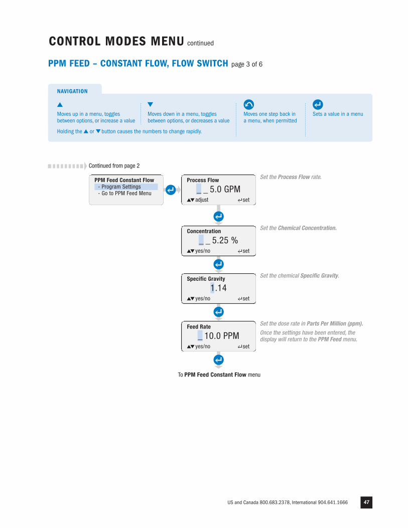
PPM FEED – CONSTANT FLOW, FLOW SWITCH page 3 of 6
Process Flow
_ _ 5.0 GPMadjust set
Concentration
_ _ 5.25 %yes/no set
Set the Process Flow rate.
Set the Chemical Concentration.
Set the chemical Specific Gravity.
Set the dose rate in Parts Per Million (ppm).
Once the settings have been entered, thedisplay will return to the PPM Feed menu.
Continued from page 2
PPM Feed Constant Flow- Program Settings- Go to PPM Feed Menu
Sets a value in a menu
NAVIGATION
Moves one step back ina menu, when permitted
Moves up in a menu, togglesbetween options, or increase a value
Moves down in a menu, togglesbetween options, or decreases a value
Holding the or button causes the numbers to change rapidly.
www.stenner.com48
CONTROL MODES MENU continued
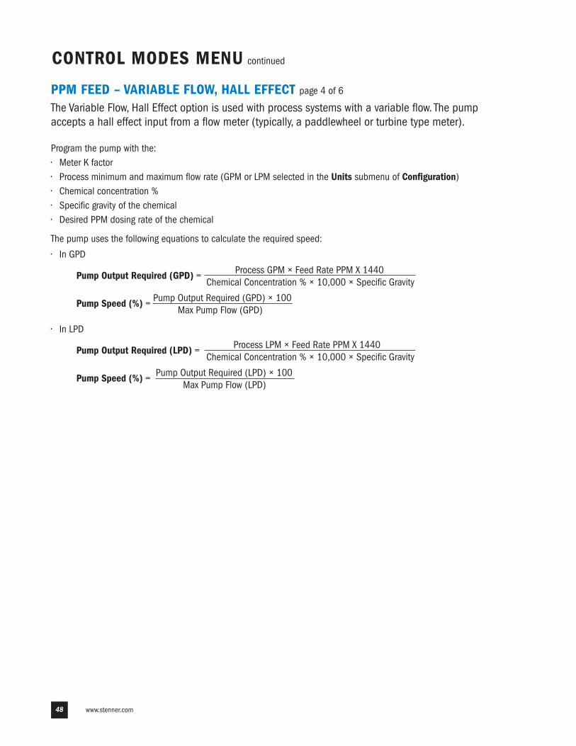
PPM FEED – VARIABLE FLOW, HALL EFFECT page 4 of 6
The Variable Flow, Hall Effect option is used with process systems with a variable flow. The pumpaccepts a hall effect input from a flow meter (typically, a paddlewheel or turbine type meter).
Program the pump with the:• Meter K factor• Process minimum and maximum flow rate (GPM or LPM selected in the Units submenu of Configuration)• Chemical concentration %• Specific gravity of the chemical• Desired PPM dosing rate of the chemical
The pump uses the following equations to calculate the required speed:
• In GPD
Pump Output Required (GPD) = Process GPM × Feed Rate PPM X 1440 Chemical Concentration % × 10,000 × Specific Gravity
Pump Speed (%) = Pump Output Required (GPD) × 100Max Pump Flow (GPD)
• In LPD
Pump Output Required (LPD) = Process LPM × Feed Rate PPM X 1440 Chemical Concentration % × 10,000 × Specific Gravity
Pump Speed (%) = Pump Output Required (LPD) × 100Max Pump Flow (LPD)
US and Canada 800.683.2378, International 904.641.1666 49
Continue to page 6
PPM Feed Variable Flow- Program Settings- Alarm Settings- GO TO PPM FEED MENU
CONTROL MODES MENU continued
PPM Feed- Constant, Flow Switch- Variable, Hall Effect- Go to Main Menu
PPM Feed Variable Flow- Program Settings- Alarm Settings- GO TO PPM FEED MENU
PPM Feed- Constant, Flow Switch- Variable, Hall Effect- Go to Main Menu
To Main Menu
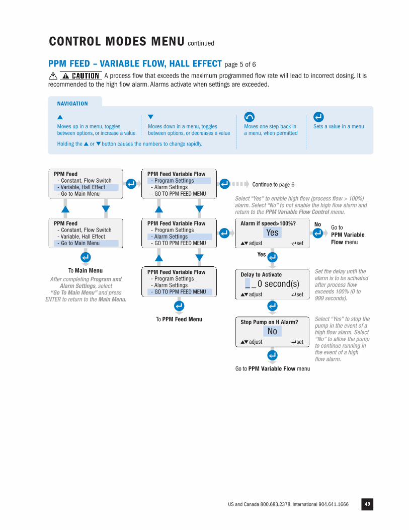
PPM FEED – VARIABLE FLOW, HALL EFFECT page 5 of 6
A process flow that exceeds the maximum programmed flow rate will lead to incorrect dosing. It isrecommended to the high flow alarm. Alarms activate when settings are exceeded.
PPM Feed Variable Flow- Program Settings- Alarm Settings- GO TO PPM FEED MENU
To PPM Feed Menu Stop Pump on H Alarm?
Noadjust set
Alarm if speed>100%?
Yesadjust set
Delay to Activate
_ _ 0 second(s)adjust set
Yes
No Go toPPM Variable Flow menu
Go to PPM Variable Flow menu
After completing Program andAlarm Settings, select
“Go To Main Menu” and pressENTER to return to the Main Menu.
Select “Yes” to enable high flow (process flow > 100%)alarm. Select “No” to not enable the high flow alarm andreturn to the PPM Variable Flow Control menu.
Set the delay until thealarm is to be activatedafter process flowexceeds 100% (0 to 999 seconds).
Select “Yes” to stop thepump in the event of ahigh flow alarm. Select“No” to allow the pumpto continue running inthe event of a high flow alarm.
Sets a value in a menu
NAVIGATION
Moves one step back ina menu, when permitted
Moves up in a menu, togglesbetween options, or increase a value
Moves down in a menu, togglesbetween options, or decreases a value
Holding the or button causes the numbers to change rapidly.
www.stenner.com50
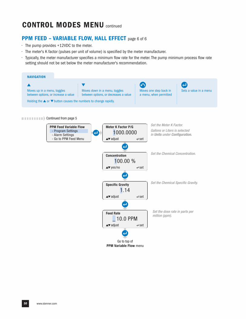
PPM FEED – VARIABLE FLOW, HALL EFFECT page 6 of 6
• The pump provides +12VDC to the meter.• The meter's K factor (pulses per unit of volume) is specified by the meter manufacturer.• Typically, the meter manufacturer specifies a minimum flow rate for the meter. The pump minimum process flow rate setting should not be set below the meter manufacturer's recommendation.
Concentration
100.00 %yes/no set
Meter K Factor P/G
1000.0000adjust set
Feed Rate
_ 10.0 PPMadjust set
Specific Gravity
1.14adjust set
Go to top ofPPM Variable Flow menu
Set the Meter K Factor.
Gallons or Liters is selectedin Units under Configuration.
Set the dose rate in parts permillion (ppm).
Set the Chemical Concentration.
Set the Chemical Specific Gravity.
CONTROL MODES MENU continued
PPM Feed Variable Flow- Program Settings- Alarm Settings- Go to PPM Feed Menu
Continued from page 5
Sets a value in a menu
NAVIGATION
Moves one step back ina menu, when permitted
Moves up in a menu, togglesbetween options, or increase a value
Moves down in a menu, togglesbetween options, or decreases a value
Holding the or button causes the numbers to change rapidly.
US and Canada 800.683.2378, International 904.641.1666 51
To Main Menu
Pump Speed
100 %adjust set
CONTROL MODES MENU continued
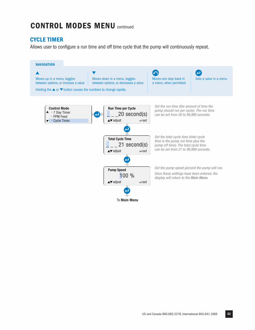
CYCLE TIMERAllows user to configure a run time and off time cycle that the pump will continuously repeat.
Set the run time (the amount of time thepump should run per cycle). The run timecan be set from 20 to 99,999 seconds.
Run Time per Cycle
_ _ _20 second(s)adjust set
Total Cycle Time
_ _ _ 21 second(s)adjust set
Set the total cycle time (total cycletime is the pump run time plus thepump off time). The total cycle timecan be set from 21 to 99,999 seconds.
Set the pump speed percent the pump will run.
Once these settings have been entered, thedisplay will return to the Main Menu.
Control Mode- 7 Day Timer- PPM Feed- Cycle Timer
Sets a value in a menu
NAVIGATION
Moves one step back ina menu, when permitted
Moves up in a menu, togglesbetween options, or increase a value
Moves down in a menu, togglesbetween options, or decreases a value
Holding the or button causes the numbers to change rapidly.
www.stenner.com52
CONTROL MODES MENU continued
GO TO MAIN MENUAllows user to return to Main Menu.
To Main Menu
To return to the Main Menu, highlight“Go To Main Menu” in the Control Modemenu and press ENTER.
Control Mode- PPM Feed- Cycle Timer- Go To Main Menu
Sets a value in a menu
NAVIGATION
Moves one step back ina menu, when permitted
Moves up in a menu, togglesbetween options, or increase a value
Moves down in a menu, togglesbetween options, or decreases a value
Holding the or button causes the numbers to change rapidly.
US and Canada 800.683.2378, International 904.641.1666 53
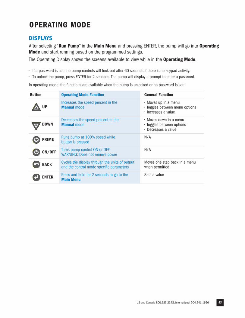
DISPLAYS After selecting “Run Pump” in the Main Menu and pressing ENTER, the pump will go into OperatingMode and start running based on the programmed settings.
The Operating Display shows the screens available to view while in the Operating Mode.
• If a password is set, the pump controls will lock out after 60 seconds if there is no keypad activity.• To unlock the pump, press ENTER for 2 seconds. The pump will display a prompt to enter a password.
In operating mode, the functions are available when the pump is unlocked or no password is set:
OPERATING MODE
Button Operating Mode Function General Function
UPIncreases the speed percent in the • Moves up in a menuManual mode • Toggles between menu options • Increases a value
DOWNDecreases the speed percent in the • Moves down in a menuManual mode • Toggles between options • Decreases a value
PRIME Runs pump at 100% speed while N/Abutton is pressed
ON/OFF Turns pump control ON or OFF N/AWARNING: Does not remove power
BACK Cycles the display through the units of output Moves one step back in a menu and the control mode specific parameters when permitted
ENTER Press and hold for 2 seconds to go to the Sets a value Main Menu
www.stenner.com54
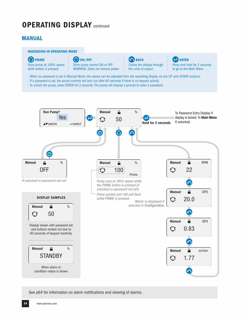
OPERATING DISPLAY continued
Run Pump?
Yesyes/no select
Manual
50%
Manual
100%
Prime
Manual
22RPM
Manual
20.0GPD
Manual
0.83GPH
Manual
1.77oz/min
Hold for 2 seconds
Manual
OFF%
To Password Entry Display ifdisplay is locked. To Main Menuif unlocked.
If unlocked or password not set.
Metric is displayed ifselected in Configuration
Pump runs at 100% speed whilethe PRIME button is pressed (ifunlocked or password not set).
See p64 for information on alarm notifications and clearing of alarms.
ENTERPress and hold for 2 secondsto go to the Main Menu
NAVIGATION IN OPERATING MODE
BACKCycles the display throughthe units of output
PRIMERuns pump at 100% speedwhile button is pressed
ON/OFF Turns pump control ON or OFF WARNING: Does not remove power.
• When no password is set in Manual Mode, the speed can be adjusted from the operating display via the UP and DOWN buttons.• If a password is set, the pump controls will lock out after 60 seconds if there is no keypad activity.• To unlock the pump, press ENTER for 2 seconds. The pump will display a prompt to enter a password.
Display shown with password setand buttons locked out due to 60 seconds of keypad inactivity.
Manual
50%
Manual
STANDBY%
When alarm or condition notice is shown
DISPLAY SAMPLES
MANUAL
Prime symbol and 100 will flashwhile PRIME is pressed.
US and Canada 800.683.2378, International 904.641.1666 55
4-20mA
100%
OPERATING DISPLAY continued
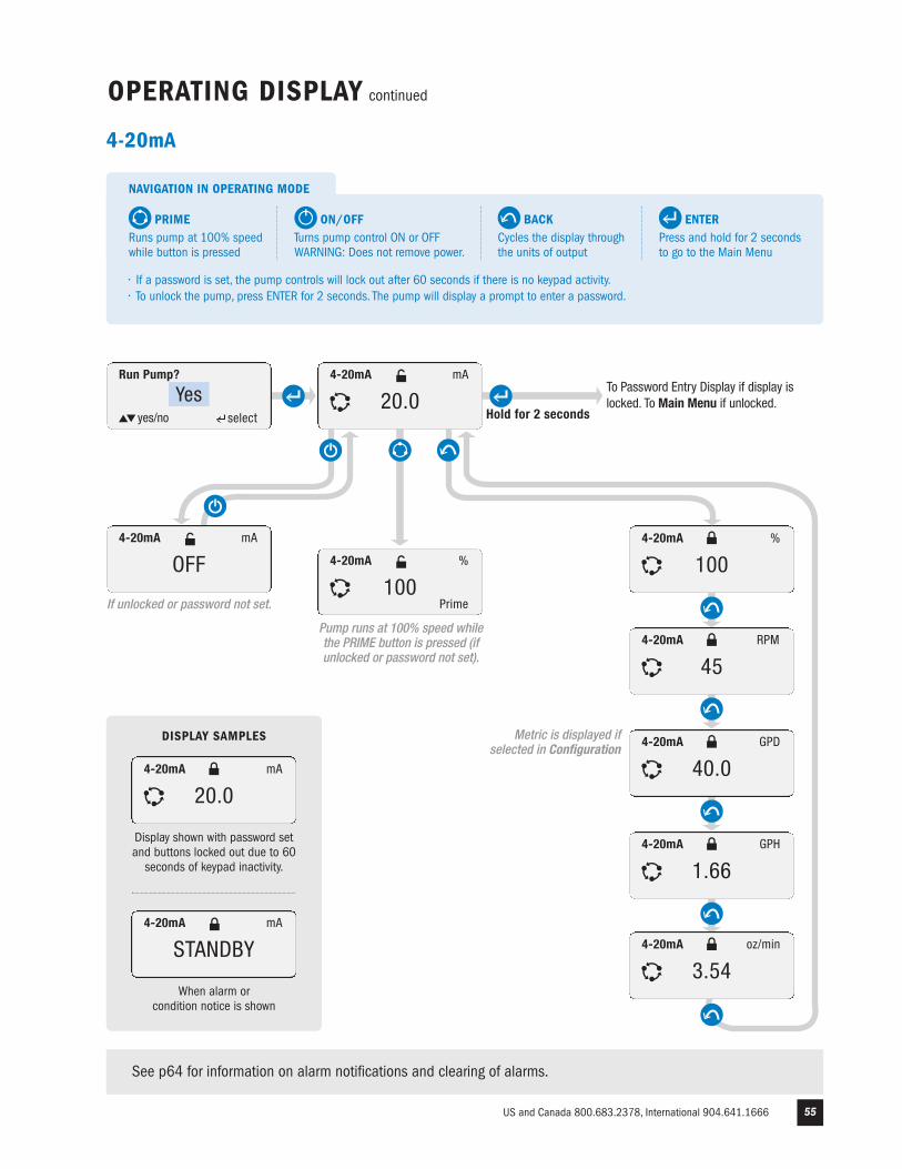
See p64 for information on alarm notifications and clearing of alarms.
Run Pump?
Yesyes/no select
4-20mA
20.0mA
Prime
4-20mA
100%
4-20mA
45RPM
Hold for 2 seconds
4-20mA
OFFmA
To Password Entry Display if display islocked. To Main Menu if unlocked.
If unlocked or password not set.
Metric is displayed ifselected in Configuration
Pump runs at 100% speed whilethe PRIME button is pressed (ifunlocked or password not set).
4-20mA
1.66GPH
4-20mA
3.54oz/min
4-20mA
40.0GPD
Display shown with password setand buttons locked out due to 60seconds of keypad inactivity.
4-20mA
20.0mA
4-20mA
STANDBYmA
When alarm or condition notice is shown
DISPLAY SAMPLES
4-20mA
ENTERPress and hold for 2 secondsto go to the Main Menu
NAVIGATION IN OPERATING MODE
BACKCycles the display throughthe units of output
PRIMERuns pump at 100% speedwhile button is pressed
ON/OFF Turns pump control ON or OFF WARNING: Does not remove power.
• If a password is set, the pump controls will lock out after 60 seconds if there is no keypad activity.• To unlock the pump, press ENTER for 2 seconds. The pump will display a prompt to enter a password.
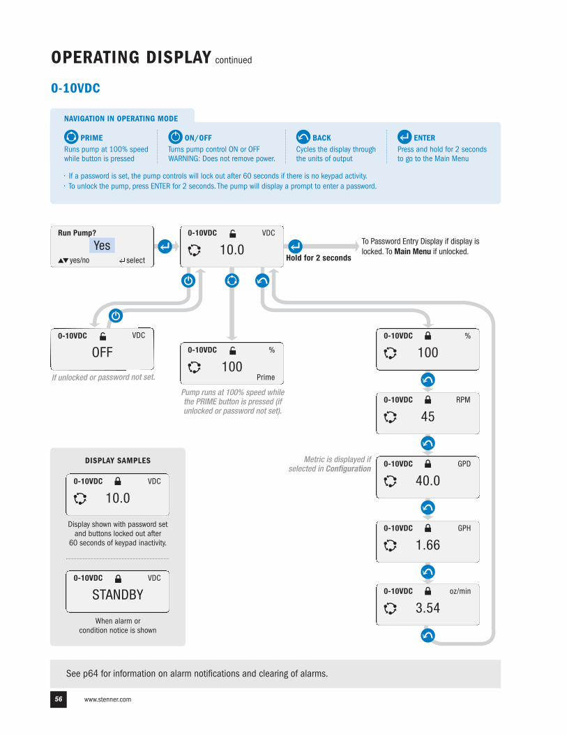
www.stenner.com56
OPERATING DISPLAY continued
See p64 for information on alarm notifications and clearing of alarms.
0-10VDC
100%
Run Pump?
Yesyes/no select
0-10VDC
10.0VDC
Prime
0-10VDC
100%
0-10VDC
45RPM
Hold for 2 seconds
0-10VDC
OFFVDC
To Password Entry Display if display islocked. To Main Menu if unlocked.
If unlocked or password not set.
Metric is displayed ifselected in Configuration
Pump runs at 100% speed whilethe PRIME button is pressed (ifunlocked or password not set).
0-10VDC
1.66GPH
0-10VDC
3.54oz/min
0-10VDC
40.0GPD
Display shown with password setand buttons locked out after
60 seconds of keypad inactivity.
0-10VDC
10.0VDC
0-10VDC
STANDBYVDC
When alarm or condition notice is shown
DISPLAY SAMPLES
0-10VDC
ENTERPress and hold for 2 secondsto go to the Main Menu
NAVIGATION IN OPERATING MODE
BACKCycles the display throughthe units of output
PRIMERuns pump at 100% speedwhile button is pressed
ON/OFF Turns pump control ON or OFF WARNING: Does not remove power.
• If a password is set, the pump controls will lock out after 60 seconds if there is no keypad activity.• To unlock the pump, press ENTER for 2 seconds. The pump will display a prompt to enter a password.
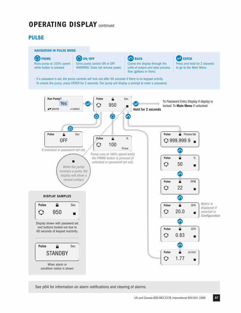
US and Canada 800.683.2378, International 904.641.1666 57
Pulse
100%
OPERATING DISPLAY continued
See p64 for information on alarm notifications and clearing of alarms.
Run Pump?
Yesyes/no select
Pulse
950Sec
Prime
Pulse
50%
Hold for 2 seconds
Pulse
OFFSec
To Password Entry Display if display islocked. To Main Menu if unlocked.
If unlocked or password not set.
Metric isdisplayed ifselected inConfiguration
Pump runs at 100% speed whilethe PRIME button is pressed (ifunlocked or password not set).
Pulse
0.83GPH
1.77oz/min
Pulse
22RPM
Pulse
20.0GPD
Pulse
Pulse
999,999.9Process Gal
Pulse
STANDBYSec
Pulse
950Sec
Display shown with password setand buttons locked out due to 60 seconds of keypad inactivity.
When alarm or condition notice is shown
DISPLAY SAMPLES
PULSE
While the pumpreceives a pulse, thedisplay will show aclosed contact
ENTERPress and hold for 2 secondsto go to the Main Menu
NAVIGATION IN PULSE MODE
BACKCycles the display through theunits of output and total processflow (gallons or liters)
PRIMERuns pump at 100% speedwhile button is pressed
ON/OFF Turns pump control ON or OFF WARNING: Does not remove power.
• If a password is set, the pump controls will lock out after 60 seconds if there is no keypad activity.• To unlock the pump, press ENTER for 2 seconds. The pump will display a prompt to enter a password.
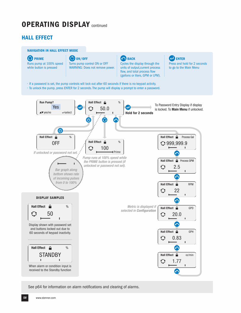
www.stenner.com58
Hall Effect
100%
OPERATING DISPLAY continued
See p64 for information on alarm notifications and clearing of alarms.
Run Pump?
Yesyes/no select
Hall Effect
50.0%
Prime
Hall Effect
999,999.9
Hall Effect
2.5Process GPM
Hold for 2 seconds
Hall Effect
OFF%
To Password Entry Display if displayis locked. To Main Menu if unlocked.
If unlocked or password not set.
Metric is displayed ifselected in Configuration
Pump runs at 100% speed whilethe PRIME button is pressed (ifunlocked or password not set).
Hall Effect
0.83GPH
1.77oz/min
Hall Effect
22RPM
Process Gal
Hall Effect
20.0GPD
Hall Effect
Hall Effect
STANDBY%
Hall Effect
50%
Display shown with password setand buttons locked out due to 60 seconds of keypad inactivity.
When alarm or condition input isreceived to the Standby function
DISPLAY SAMPLES
HALL EFFECT
Bar graph alongbottom shows rateof incoming pulsesfrom 0 to 100%
ENTERPress and hold for 2 secondsto go to the Main Menu
NAVIGATION IN HALL EFFECT MODE
BACKCycles the display through theunits of output,current processflow, and total process flow(gallons or liters, GPM or LPM).
PRIMERuns pump at 100% speedwhile button is pressed
ON/OFF Turns pump control ON or OFF WARNING: Does not remove power.
• If a password is set, the pump controls will lock out after 60 seconds if there is no keypad activity.• To unlock the pump, press ENTER for 2 seconds. The pump will display a prompt to enter a password.
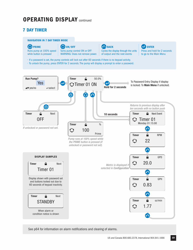
US and Canada 800.683.2378, International 904.641.1666 59
Timer
100%
OPERATING DISPLAY continued
Run Pump?
Yesyes/no select
Timer
Timer 01 ON50.0%
Prime
Timer
Timer 01Next Event
Timer
22RPM
Hold for 2 seconds
Timer
OFFNext
To Password Entry Display if displayis locked. To Main Menu if unlocked.
If unlocked or password not set.
Metric is displayed ifselected in Configuration
Pump runs at 100% speed whilethe PRIME button is pressed (ifunlocked or password not set).
Timer
0.83GPH
Timer
1.77oz/min
Timer
20.0GPD
Monday 01:15:00
Returns to previous display afterten seconds with no button push
10 seconds
See p64 for information on alarm notifications and clearing of alarms.
Display shown with password set and buttons locked out due to 60 seconds of keypad inactivity.
When alarm or condition notice is shown
DISPLAY SAMPLES
Timer
STANDBYNext
Timer
Timer 01Next
7 DAY TIMER
ENTERPress and hold for 2 secondsto go to the Main Menu
NAVIGATION IN 7 DAY TIMER MODE
BACKCycles the display through the unitsof output and the next events
PRIMERuns pump at 100% speedwhile button is pressed
ON/OFF Turns pump control ON or OFF WARNING: Does not remove power.
• If a password is set, the pump controls will lock out after 60 seconds if there is no keypad activity.• To unlock the pump, press ENTER for 2 seconds. The pump will display a prompt to enter a password.
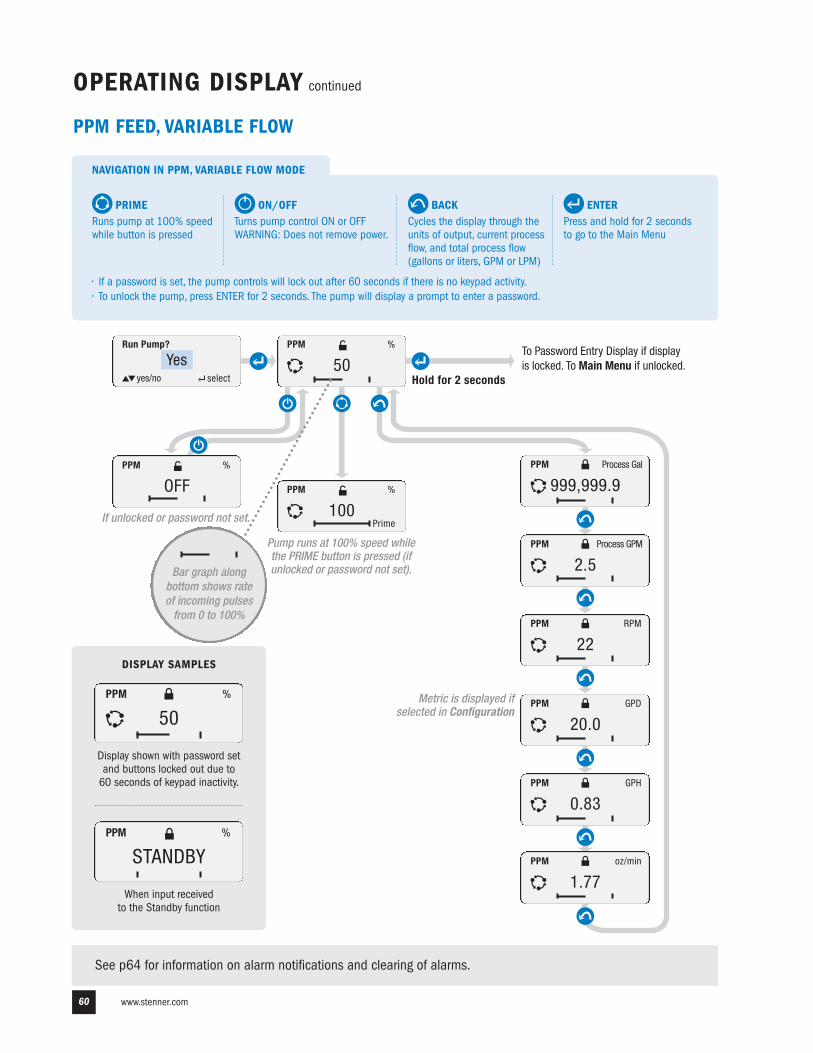
www.stenner.com60
OPERATING DISPLAY continued
See p64 for information on alarm notifications and clearing of alarms.
PPM
STANDBY%
Display shown with password setand buttons locked out due to 60 seconds of keypad inactivity.
When input received to the Standby function
DISPLAY SAMPLES
PPM
50%
PPM FEED, VARIABLE FLOW
ENTERPress and hold for 2 secondsto go to the Main Menu
NAVIGATION IN PPM, VARIABLE FLOW MODE
BACKCycles the display through theunits of output, current processflow, and total process flow(gallons or liters, GPM or LPM)
PRIMERuns pump at 100% speedwhile button is pressed
ON/OFF Turns pump control ON or OFF WARNING: Does not remove power.
• If a password is set, the pump controls will lock out after 60 seconds if there is no keypad activity.• To unlock the pump, press ENTER for 2 seconds. The pump will display a prompt to enter a password.
PPM
100%
Run Pump?
Yesyes/no select
PPM
50%
Prime
PPM
999,999.9
PPM
2.5Process GPM
Hold for 2 seconds
PPM
OFF%
To Password Entry Display if displayis locked. To Main Menu if unlocked.
If unlocked or password not set.
Metric is displayed ifselected in Configuration
Pump runs at 100% speed whilethe PRIME button is pressed (ifunlocked or password not set).
PPM
0.83GPH
1.77oz/min
PPM
22RPM
Process Gal
PPM
20.0GPD
PPM
Bar graph alongbottom shows rateof incoming pulsesfrom 0 to 100%
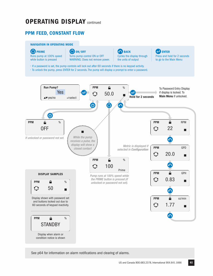
US and Canada 800.683.2378, International 904.641.1666 61
PPM
STANDBY%
Display shown with password setand buttons locked out due to 60 seconds of keypad inactivity.
Display when alarm or condition notice is shown
DISPLAY SAMPLES
PPM
50%
OPERATING DISPLAY continued
Run Pump?
Yesyes/no select
PPM
100%
Prime
PPM
22RPM
PPM
20.0GPD
PPM
0.83GPH
PPM
1.77oz/min
Hold for 2 seconds
PPM
OFF%
To Password Entry Displayif display is locked. ToMain Menu if unlocked.
If unlocked or password not set.
Metric is displayed ifselected in Configuration
Pump runs at 100% speed whilethe PRIME button is pressed (ifunlocked or password not set).
See p64 for information on alarm notifications and clearing of alarms.
50.0PPM %
While the pumpreceives a pulse, thedisplay will show aclosed contact
PPM FEED, CONSTANT FLOW
ENTERPress and hold for 2 secondsto go to the Main Menu
NAVIGATION IN OPERATING MODE
BACKCycles the display throughthe units of output
PRIMERuns pump at 100% speedwhile button is pressed
ON/OFF Turns pump control ON or OFF WARNING: Does not remove power.
• If a password is set, the pump controls will lock out after 60 seconds if there is no keypad activity.• To unlock the pump, press ENTER for 2 seconds. The pump will display a prompt to enter a password.
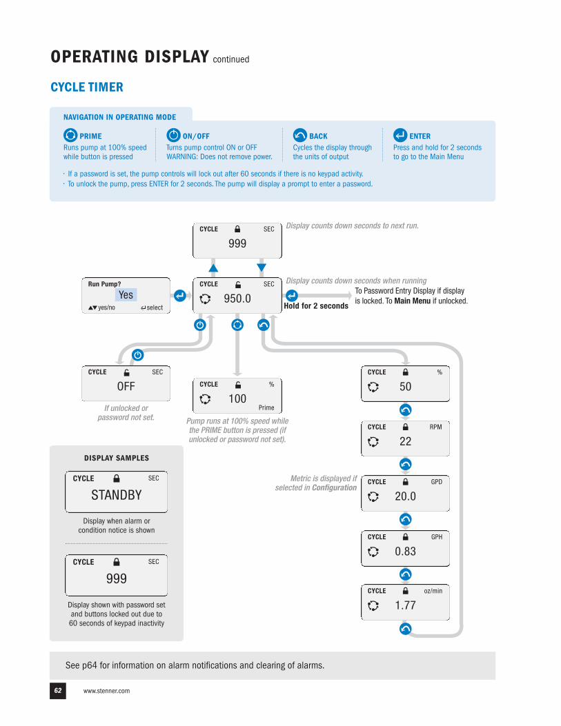
www.stenner.com62
OPERATING DISPLAY continued
See p64 for information on alarm notifications and clearing of alarms.
CYCLE
100%
Run Pump?
Yesyes/no select
CYCLE
950.0SEC
Prime
CYCLE
50%
CYCLE
22RPM
Hold for 2 seconds
CYCLE
OFFSEC
To Password Entry Display if displayis locked. To Main Menu if unlocked.
If unlocked or password not set.
Metric is displayed ifselected in Configuration
Pump runs at 100% speed whilethe PRIME button is pressed (ifunlocked or password not set).
Display counts down seconds to next run.CYCLE
999SEC
CYCLE
0.83GPH
CYCLE
1.77oz/min
CYCLE
20.0GPD
Display when alarm or condition notice is shown
DISPLAY SAMPLES
CYCLE
STANDBYSEC
Display counts down seconds when running
CYCLE TIMER
ENTERPress and hold for 2 secondsto go to the Main Menu
NAVIGATION IN OPERATING MODE
BACKCycles the display throughthe units of output
PRIMERuns pump at 100% speedwhile button is pressed
ON/OFF Turns pump control ON or OFF WARNING: Does not remove power.
• If a password is set, the pump controls will lock out after 60 seconds if there is no keypad activity.• To unlock the pump, press ENTER for 2 seconds. The pump will display a prompt to enter a password.
CYCLE
999SEC
Display shown with password setand buttons locked out due to 60 seconds of keypad inactivity
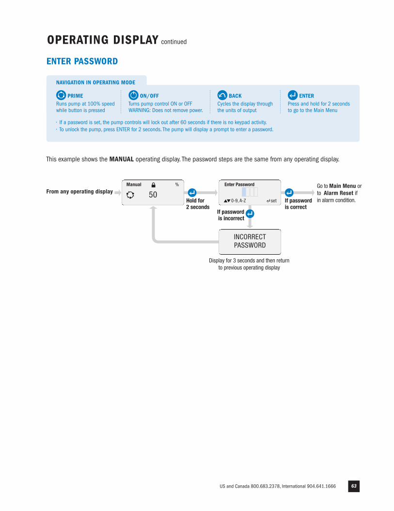
US and Canada 800.683.2378, International 904.641.1666 63
OPERATING DISPLAY continued
Hold for 2 seconds
ENTER PASSWORD
Enter Password
0-9, A-Z set
From any operating display
INCORRECT PASSWORD
If passwordis correct
If passwordis incorrect
Go to Main Menu or to Alarm Reset if in alarm condition.
Display for 3 seconds and then return to previous operating display
Manual
50%
This example shows the MANUAL operating display. The password steps are the same from any operating display.
ENTERPress and hold for 2 secondsto go to the Main Menu
NAVIGATION IN OPERATING MODE
BACKCycles the display throughthe units of output
PRIMERuns pump at 100% speedwhile button is pressed
ON/OFF Turns pump control ON or OFF WARNING: Does not remove power.
• If a password is set, the pump controls will lock out after 60 seconds if there is no keypad activity.• To unlock the pump, press ENTER for 2 seconds. The pump will display a prompt to enter a password.
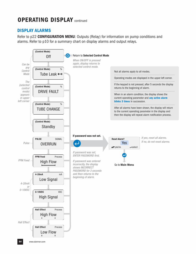
Hall Effect
www.stenner.com64
OPERATING DISPLAY continued
Reset Alarm?
Yesyes/no select
Hall Effect
Low FlowProcess
Hall Effect
High FlowProcess
0-10VDC
High SignalVDC
4-20mA
Low SignalmA
PPM Feed
High FlowProcess
PULSE
OVERRUNSIGNAL
(Control Mode)
Standby
(Control Mode)
TUBE CHANGE%
(Control Mode)
Off
(Control Mode)
Tube Leak%
(Control Mode)
DRIVE FAULT%
PPM Feed
Pulse
Can beany
ControlMode
If password was not set.
If password was set,ENTER PASSWORD first.
If password was enteredincorrectly, the displayshows INCORRECTPASSWORD for 3 secondsand then returns to thebeginning of alarm.
If yes, reset all alarms.If no, do not reset alarms.
DISPLAY ALARMSRefer to p22 CONFIGURATION MENU: Outputs (Relay) for information on pump conditions andalarms. Refer to p10 for a summary chart on display alarms and output relays.
Go to Main Menu
Not all alarms apply to all modes.
Operating modes are displayed in the upper left corner.
If the keypad is not pressed, after 5 seconds the displayreturns to the beginning of alarm.
When in an alarm condition, the display shows thecurrent operating parameter and any active alarmblinks 3 times in succession.
After all alarms have been shown, the display will returnto the current operating parameter in the display andthen the display will repeat alarm notification process.
4-20mA or
0-10VDC
The(selectedcontrolmode)
appearsin upper
left corner
Return to Selected Control Mode
When ON/OFF is pressedagain, display returns toselected control mode.
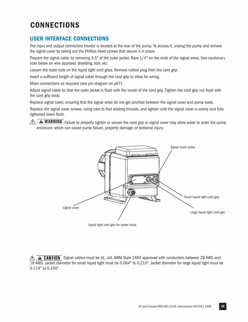
US and Canada 800.683.2378, International 904.641.1666 65
CONNECTIONS
USER INTERFACE CONNECTIONSThe input and output connection header is located at the rear of the pump. To access it, unplug the pump and removethe signal cover by taking out the Phillips head screws that secure it in place.
Prepare the signal cable by removing 3.5" of the outer jacket. Bare 1/4" on the ends of the signal wires. See cautionarynote below on wire approval, shielding, size, etc.
Loosen the outer nuts on the liquid tight cord grips. Remove rubber plug from the cord grip.
Insert a sufficient length of signal cable through the cord grip to allow for wiring.
Make connections as required (see pin diagram on p67).
Adjust signal cable so that the outer jacket is flush with the inside of the cord grip. Tighten the cord grip nut flush withthe cord grip body.
Replace signal cover, ensuring that the signal wires do not get pinched between the signal cover and pump body.
Replace the signal cover screws, using care to find existing threads, and tighten until the signal cover is evenly and fullytightened down flush.
Failure to properly tighten or secure the cord grip or signal cover may allow water to enter the pumpenclosure, which can cause pump failure, property damage, or personal injury.
Signal cables must be UL, cUL AWM Style 2464 approved with conductors between 28 AWG and 18 AWG. Jacket diameter for small liquid tight must be 0.064" to 0.210". Jacket diameter for large liquid tight must be0.114" to 0.250".
Signal cover
Liquid tight cord grip for power input
Signal cover screw
Small liquid tight cord grip
Large liquid tight cord grip
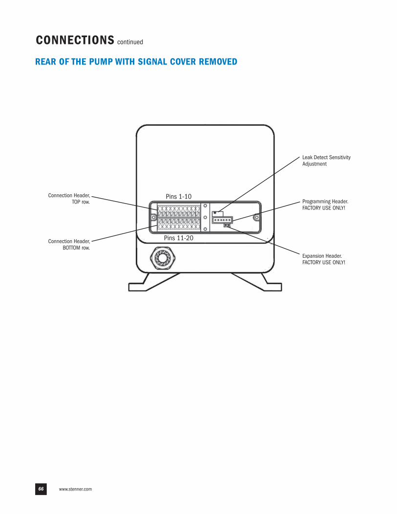
www.stenner.com66
REAR OF THE PUMP WITH SIGNAL COVER REMOVED
Leak Detect SensitivityAdjustment
Programming Header. FACTORY USE ONLY!
Expansion Header.FACTORY USE ONLY!
Connection Header,BOTTOM row.
Connection Header,TOP row.
CONNECTIONS continued
Pins 1-10
Pins 11-20
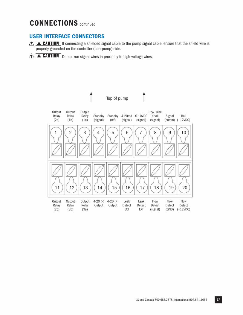
US and Canada 800.683.2378, International 904.641.1666 67
USER INTERFACE CONNECTORSIf connecting a shielded signal cable to the pump signal cable, ensure that the shield wire is
properly grounded on the controller (non-pump) side.
Do not run signal wires in proximity to high voltage wires.
Top of pump
1 2 3 4 5 6 7 8 9 10
11 12 13 14 15 16 17 18 19 20
CONNECTIONS continued
OutputRelay(2a)
OutputRelay (1b)
OutputRelay(1a)
Standby(signal)
Standby(ref)
4-20mA(signal)
0-10VDC(signal)
Dry/Pulse/Hall(signal)
Signal(comm)
Hall(+12VDC)
OutputRelay(2b)
OutputRelay (3b)
OutputRelay(3a)
4-20 (–)Output
4-20 (+)Output
LeakDetect EXT
LeakDetectEXT
FlowDetect(signal)
FlowDetect(GND)
FlowDetect
(+12VDC)
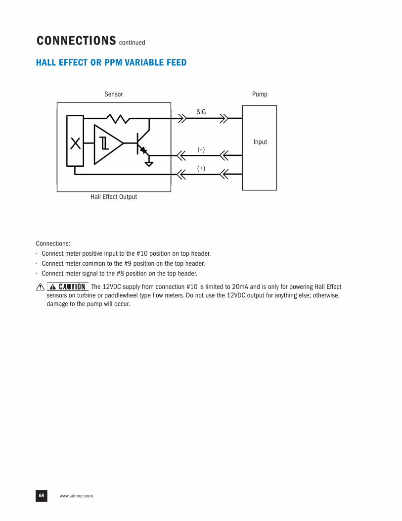
www.stenner.com68
HALL EFFECT OR PPM VARIABLE FEED
Connections:• Connect meter positive input to the #10 position on top header.• Connect meter common to the #9 position on the top header.• Connect meter signal to the #8 position on the top header.
The 12VDC supply from connection #10 is limited to 20mA and is only for powering Hall Effectsensors on turbine or paddlewheel type flow meters. Do not use the 12VDC output for anything else; otherwise,damage to the pump will occur.
Sensor Pump
Input
Hall Effect Output
SIG
(+)
(–)
CONNECTIONS continued
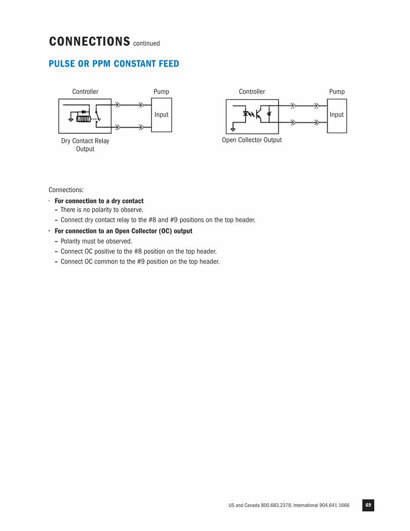
US and Canada 800.683.2378, International 904.641.1666 69
PULSE OR PPM CONSTANT FEED
Connections:
• For connection to a dry contact– There is no polarity to observe.– Connect dry contact relay to the #8 and #9 positions on the top header.
• For connection to an Open Collector (OC) output– Polarity must be observed. – Connect OC positive to the #8 position on the top header.– Connect OC common to the #9 position on the top header.
Controller Pump
Input
Dry Contact RelayOutput
Controller Pump
Input
Open Collector Output
CONNECTIONS continued
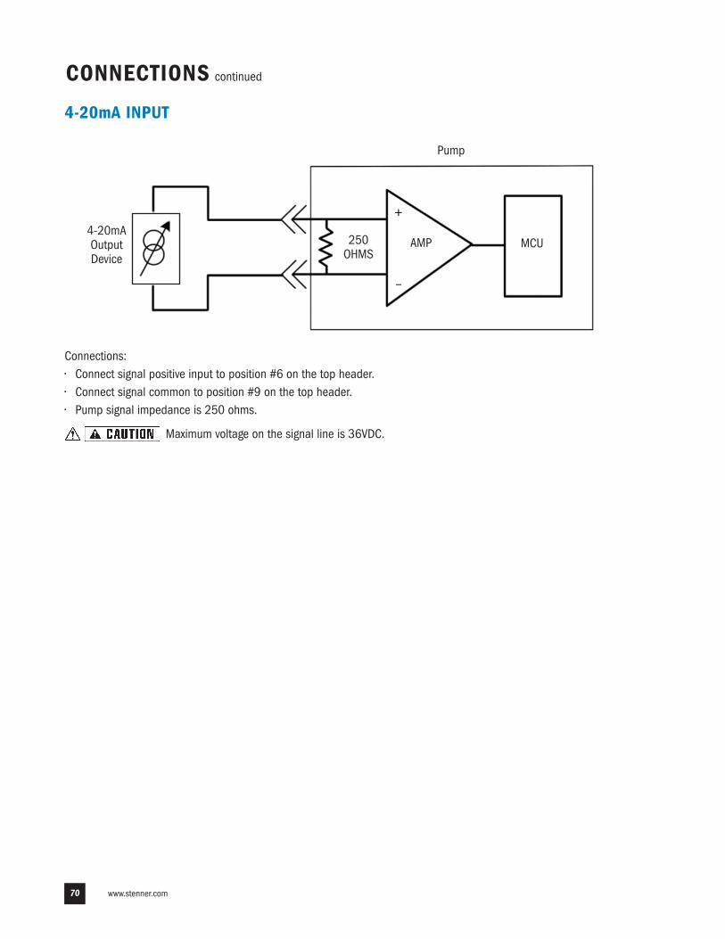
www.stenner.com70
4-20mA INPUT
Connections:• Connect signal positive input to position #6 on the top header.• Connect signal common to position #9 on the top header.• Pump signal impedance is 250 ohms.
Maximum voltage on the signal line is 36VDC.
Pump
AMP4-20mAOutputDevice
MCU250OHMS
CONNECTIONS continued
+
–
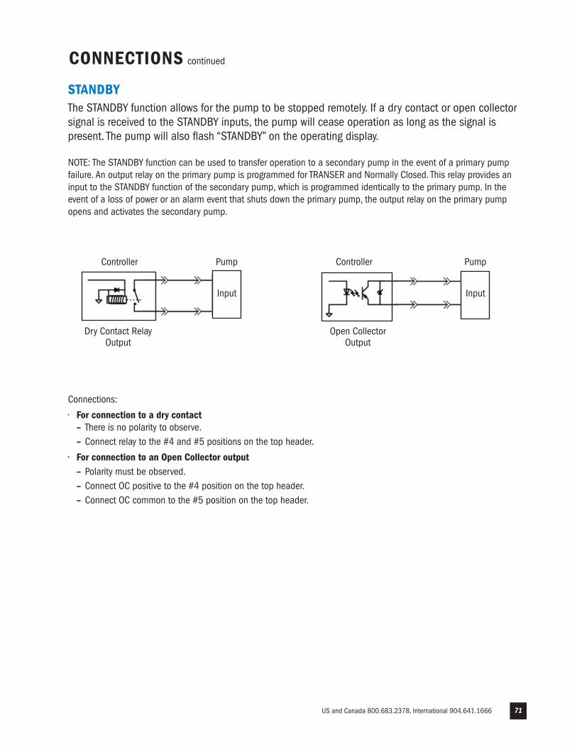
US and Canada 800.683.2378, International 904.641.1666 71
STANDBYThe STANDBY function allows for the pump to be stopped remotely. If a dry contact or open collectorsignal is received to the STANDBY inputs, the pump will cease operation as long as the signal ispresent. The pump will also flash “STANDBY” on the operating display.
NOTE: The STANDBY function can be used to transfer operation to a secondary pump in the event of a primary pumpfailure. An output relay on the primary pump is programmed for TRANSER and Normally Closed. This relay provides aninput to the STANDBY function of the secondary pump, which is programmed identically to the primary pump. In theevent of a loss of power or an alarm event that shuts down the primary pump, the output relay on the primary pumpopens and activates the secondary pump.
Connections:
• For connection to a dry contact– There is no polarity to observe.– Connect relay to the #4 and #5 positions on the top header.
• For connection to an Open Collector output– Polarity must be observed. – Connect OC positive to the #4 position on the top header.– Connect OC common to the #5 position on the top header.
Controller Pump
Input
Dry Contact RelayOutput
Controller Pump
Input
Open CollectorOutput
CONNECTIONS continued
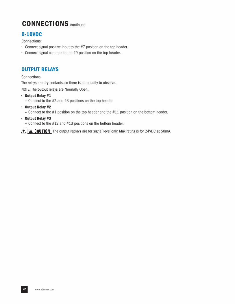
www.stenner.com72
0-10VDCConnections:• Connect signal positive input to the #7 position on the top header.• Connect signal common to the #9 position on the top header.
CONNECTIONS continued
OUTPUT RELAYSConnections:The relays are dry contacts, so there is no polarity to observe.
NOTE: The output relays are Normally Open.
• Output Relay #1– Connect to the #2 and #3 positions on the top header.
• Output Relay #2– Connect to the #1 position on the top header and the #11 position on the bottom header.
• Output Relay #3– Connect to the #12 and #13 positions on the bottom header.
The output replays are for signal level only. Max rating is for 24VDC at 50mA.
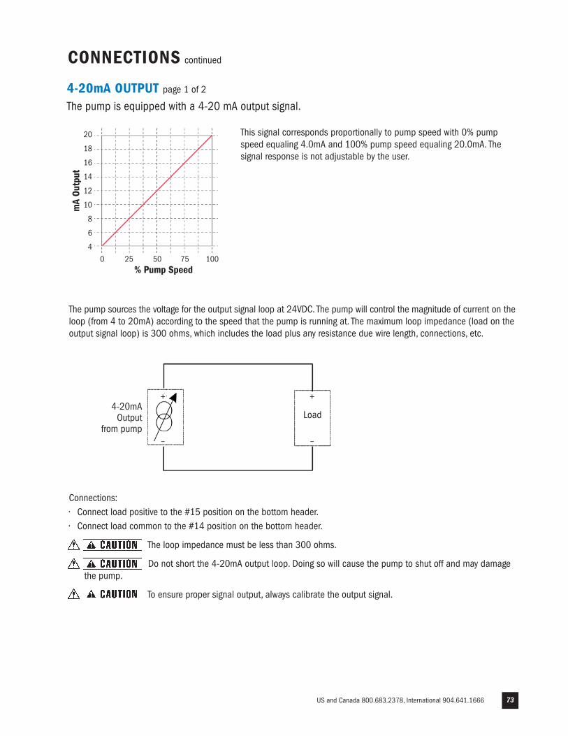
US and Canada 800.683.2378, International 904.641.1666 73
4-20mA OUTPUT page 1 of 2
The pump is equipped with a 4-20 mA output signal.
This signal corresponds proportionally to pump speed with 0% pumpspeed equaling 4.0mA and 100% pump speed equaling 20.0mA. Thesignal response is not adjustable by the user.
CONNECTIONS continued
The pump sources the voltage for the output signal loop at 24VDC. The pump will control the magnitude of current on theloop (from 4 to 20mA) according to the speed that the pump is running at. The maximum loop impedance (load on theoutput signal loop) is 300 ohms, which includes the load plus any resistance due wire length, connections, etc.
Connections:• Connect load positive to the #15 position on the bottom header.• Connect load common to the #14 position on the bottom header.
The loop impedance must be less than 300 ohms.
Do not short the 4-20mA output loop. Doing so will cause the pump to shut off and may damage the pump.
To ensure proper signal output, always calibrate the output signal.
0 25 50 75 100% Pump Speed
20
18
16
14
12
10
8
6
4
mA
Outp
ut
4-20mAOutput
from pumpLoad
+
–
+
–
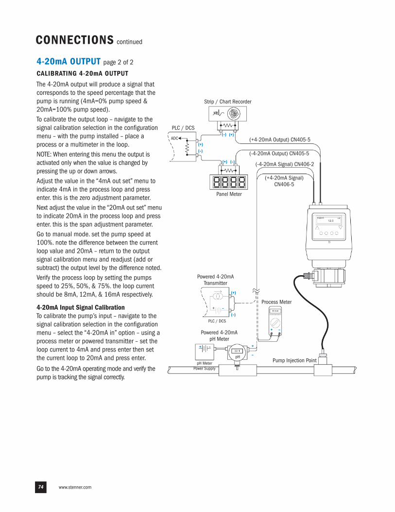
www.stenner.com74
CONNECTIONS continued
Strip / Chart Recorder
PLC / DCS
(+4-20mA Output) CN405-5
(-4-20mA Output) CN405-5
(-4-20mA Signal) CN406-2
(+4-20mA Signal)CN406-5
Panel Meter
ADC(+)(–)
(–) (+)
(+) (–)
Powered 4-20mATransmitter
+ –
(+)
(–)PLC / DCS
pH MeterPower Supply
+ –
Powered 4-20mApH Meter
pH
+
–
+ –
Process Meter
Pump Injection Point
4-20mA OUTPUT page 2 of 2
CALIBRATING 4-20mA OUTPUT
The 4-20mA output will produce a signal thatcorresponds to the speed percentage that thepump is running (4mA=0% pump speed &20mA=100% pump speed).To calibrate the output loop – navigate to thesignal calibration selection in the configurationmenu – with the pump installed – place aprocess or a multimeter in the loop.NOTE: When entering this menu the output isactivated only when the value is changed bypressing the up or down arrows. Adjust the value in the “4mA out set” menu toindicate 4mA in the process loop and pressenter. this is the zero adjustment parameter.Next adjust the value in the “20mA out set” menuto indicate 20mA in the process loop and pressenter. this is the span adjustment parameter.Go to manual mode. set the pump speed at100%. note the difference between the currentloop value and 20mA – return to the outputsignal calibration menu and readjust (add orsubtract) the output level by the difference noted.Verify the process loop by setting the pumpsspeed to 25%, 50%, & 75%. the loop currentshould be 8mA, 12mA, & 16mA respectively.
4-20mA Input Signal CalibrationTo calibrate the pump’s input – navigate to thesignal calibration selection in the configurationmenu – select the “4-20mA in” option – using aprocess meter or powered transmitter – set theloop current to 4mA and press enter then setthe current loop to 20mA and press enter.
Go to the 4-20mA operating mode and verify thepump is tracking the signal correctly.
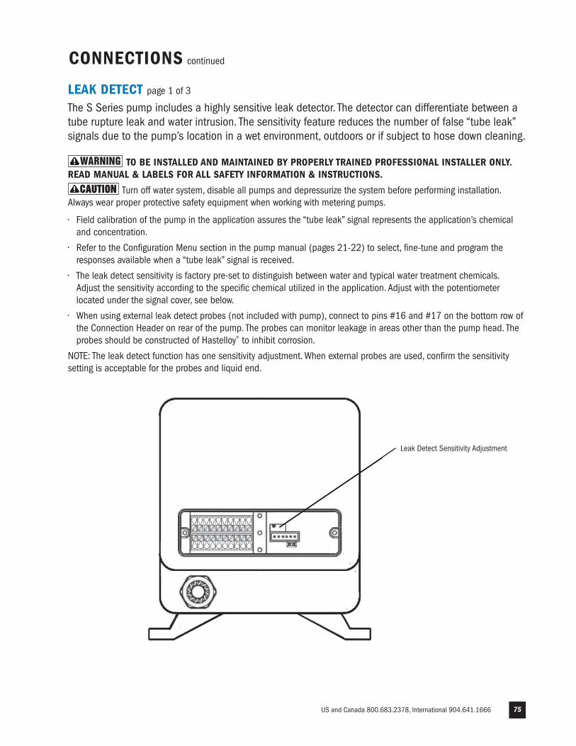
US and Canada 800.683.2378, International 904.641.1666 75
LEAK DETECT page 1 of 3
The S Series pump includes a highly sensitive leak detector. The detector can differentiate between atube rupture leak and water intrusion. The sensitivity feature reduces the number of false “tube leak”signals due to the pump’s location in a wet environment, outdoors or if subject to hose down cleaning.
TO BE INSTALLED AND MAINTAINED BY PROPERLY TRAINED PROFESSIONAL INSTALLER ONLY.READ MANUAL & LABELS FOR ALL SAFETY INFORMATION & INSTRUCTIONS.
Turn off water system, disable all pumps and depressurize the system before performing installation.Always wear proper protective safety equipment when working with metering pumps.
• Field calibration of the pump in the application assures the “tube leak” signal represents the application’s chemical and concentration.
• Refer to the Configuration Menu section in the pump manual (pages 21-22) to select, fine-tune and program the responses available when a “tube leak” signal is received.
• The leak detect sensitivity is factory pre-set to distinguish between water and typical water treatment chemicals. Adjust the sensitivity according to the specific chemical utilized in the application. Adjust with the potentiometer located under the signal cover, see below.
• When using external leak detect probes (not included with pump), connect to pins #16 and #17 on the bottom row of the Connection Header on rear of the pump. The probes can monitor leakage in areas other than the pump head. The probes should be constructed of Hastelloy® to inhibit corrosion.
NOTE: The leak detect function has one sensitivity adjustment. When external probes are used, confirm the sensitivitysetting is acceptable for the probes and liquid end.
Leak Detect Sensitivity Adjustment
CONNECTIONS continued
CAUTIONCAUTION
WARNING
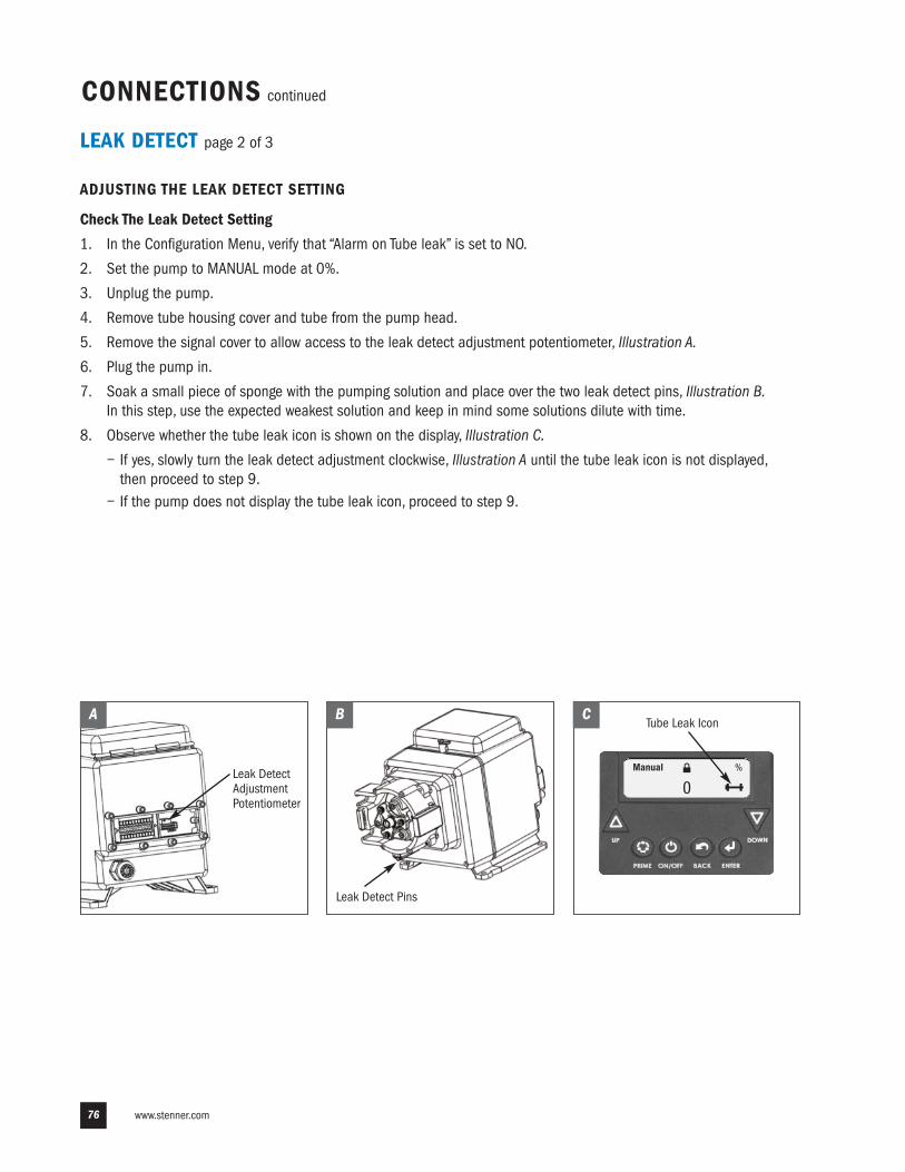
www.stenner.com76
LEAK DETECT page 2 of 3
ADJUSTING THE LEAK DETECT SETTING
Check The Leak Detect Setting
1. In the Configuration Menu, verify that “Alarm on Tube leak” is set to NO.
2. Set the pump to MANUAL mode at 0%.
3. Unplug the pump.
4. Remove tube housing cover and tube from the pump head.
5. Remove the signal cover to allow access to the leak detect adjustment potentiometer, Illustration A.
6. Plug the pump in.
7. Soak a small piece of sponge with the pumping solution and place over the two leak detect pins, Illustration B.In this step, use the expected weakest solution and keep in mind some solutions dilute with time.
8. Observe whether the tube leak icon is shown on the display, Illustration C.
− If yes, slowly turn the leak detect adjustment clockwise, Illustration A until the tube leak icon is not displayed, then proceed to step 9. �
− If the pump does not display the tube leak icon, proceed to step 9.
CONNECTIONS continued
MAIN MENU
-CONFIGURATION
-CONTROL MODE
-RUN PUMP
Manual
0%
B
Leak Detect Pins
Tube Leak IconC
Leak DetectAdjustmentPotentiometer
A
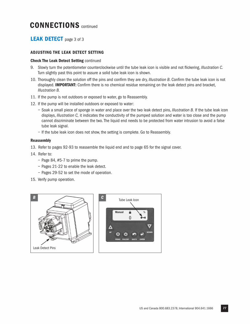
US and Canada 800.683.2378, International 904.641.1666 77
LEAK DETECT page 3 of 3
ADJUSTING THE LEAK DETECT SETTING
Check The Leak Detect Setting continued
9. Slowly turn the potentiometer counterclockwise until the tube leak icon is visible and not flickering, Illustration C.Turn slightly past this point to assure a solid tube leak icon is shown.
10. Thoroughly clean the solution off the pins and confirm they are dry, Illustration B. Confirm the tube leak icon is not displayed. IMPORTANT: Confirm there is no chemical residue remaining on the leak detect pins and bracket, Illustration B.
11. If the pump is not outdoors or exposed to water, go to Reassembly.
12. If the pump will be installed outdoors or exposed to water:− Soak a small piece of sponge in water and place over the two leak detect pins, Illustration B. If the tube leak icondisplays, Illustration C, it indicates the conductivity of the pumped solution and water is too close and the pump cannot discriminate between the two. The liquid end needs to be protected from water intrusion to avoid a false tube leak signal.
− If the tube leak icon does not show, the setting is complete. Go to Reassembly. �
Reassembly
13. Refer to pages 92-93 to reassemble the liquid end and to page 65 for the signal cover. �
14. Refer to:− Page 84, #5-7 to prime the pump.− Pages 21-22 to enable the leak detect.− Pages 29-52 to set the mode of operation.
15. Verify pump operation.
CONNECTIONS continued
MAIN MENU
-CONFIGURATION
-CONTROL MODE
-RUN PUMP
Manual
0%
B
Leak Detect Pins
Tube Leak IconC
www.stenner.com78
INSTALLATION
ADDITIONAL SAFETY INSTRUCTIONS
NOTICE: Indicates special instructions or general mandatory action.
Read all safety hazards before installing or servicing the pump. The pump is designed for installation and serviceby properly trained personnel.
Use all required personal protective equipment when working on or near a chemical metering pump.
Install the pump so that it is in compliance with all national and local plumbing and electrical codes.
Use the proper product to treat potable water systems, use only chemicals listed or approved for use.
Inspect tube frequently for leakage, deterioration, or wear. Schedule a regular pump tube maintenance change toprevent chemical damage to pump and/or spillage.
Recommended mounting is vertical with pump head pointed downward.
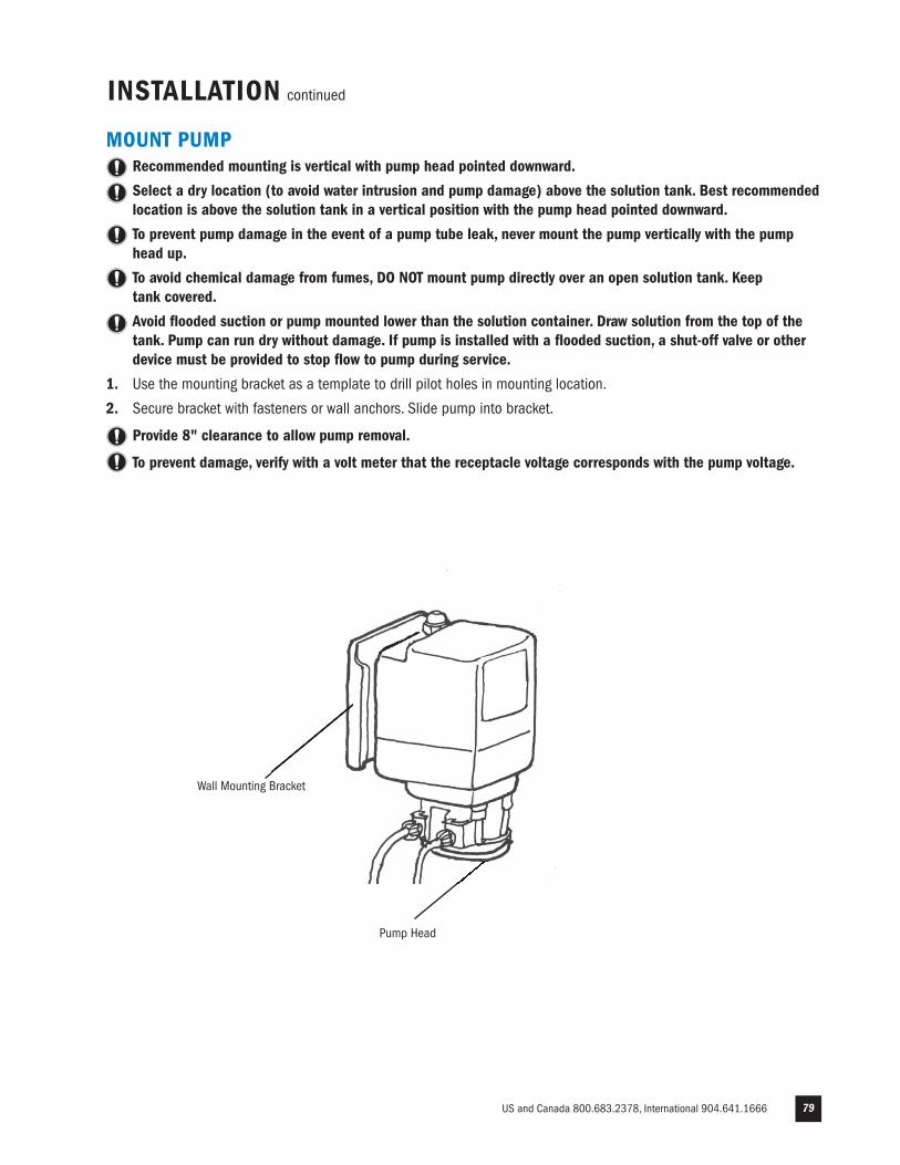
US and Canada 800.683.2378, International 904.641.1666 79
INSTALLATION continued
Pump Head
MOUNT PUMPRecommended mounting is vertical with pump head pointed downward.
Select a dry location (to avoid water intrusion and pump damage) above the solution tank. Best recommendedlocation is above the solution tank in a vertical position with the pump head pointed downward.
To prevent pump damage in the event of a pump tube leak, never mount the pump vertically with the pumphead up.
To avoid chemical damage from fumes, DO NOT mount pump directly over an open solution tank. Keep tank covered.
Avoid flooded suction or pump mounted lower than the solution container. Draw solution from the top of thetank. Pump can run dry without damage. If pump is installed with a flooded suction, a shut-off valve or otherdevice must be provided to stop flow to pump during service.
1. Use the mounting bracket as a template to drill pilot holes in mounting location.
2. Secure bracket with fasteners or wall anchors. Slide pump into bracket.
Provide 8" clearance to allow pump removal.
To prevent damage, verify with a volt meter that the receptacle voltage corresponds with the pump voltage.
Wall Mounting Bracket
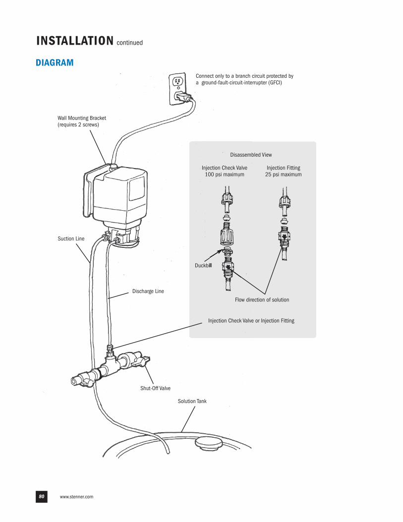
www.stenner.com80
Injection Check Valve or Injection Fitting
Discharge Line
Solution Tank
Connect only to a branch circuit protected bya ground-fault-circuit-interrupter (GFCI)
Suction Line
Shut-Off Valve
Duckbill
Injection Fitting25 psi maximum
Injection Check Valve100 psi maximum
Flow direction of solution
Disassembled View
Wall Mounting Bracket (requires 2 screws)
INSTALLATION continued
DIAGRAM
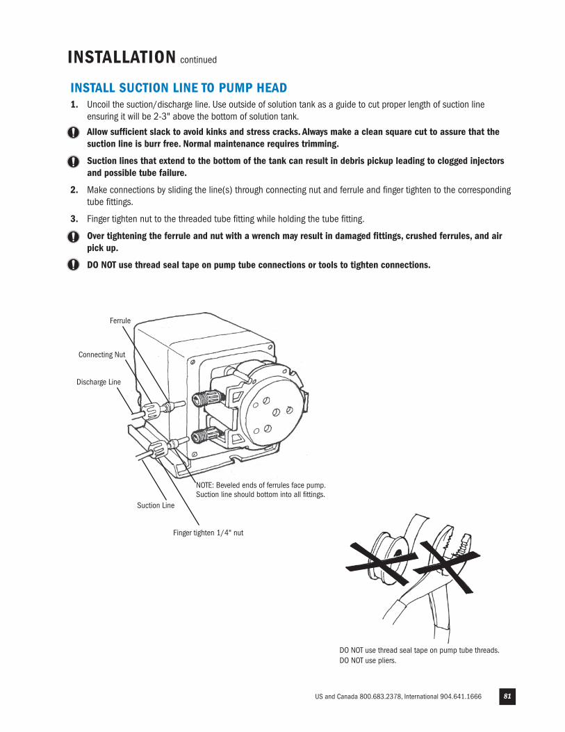
US and Canada 800.683.2378, International 904.641.1666 81
INSTALLATION continued
INSTALL SUCTION LINE TO PUMP HEAD1. Uncoil the suction/discharge line. Use outside of solution tank as a guide to cut proper length of suction line
ensuring it will be 2-3" above the bottom of solution tank.
Allow sufficient slack to avoid kinks and stress cracks. Always make a clean square cut to assure that thesuction line is burr free. Normal maintenance requires trimming.
Suction lines that extend to the bottom of the tank can result in debris pickup leading to clogged injectorsand possible tube failure.
2. Make connections by sliding the line(s) through connecting nut and ferrule and finger tighten to the correspondingtube fittings.
3. Finger tighten nut to the threaded tube fitting while holding the tube fitting.
Over tightening the ferrule and nut with a wrench may result in damaged fittings, crushed ferrules, and airpick up.
DO NOT use thread seal tape on pump tube connections or tools to tighten connections.
DO NOT use thread seal tape on pump tube threads.DO NOT use pliers.
Suction Line
Finger tighten 1/4" nut
Discharge Line
Connecting Nut
NOTE: Beveled ends of ferrules face pump.Suction line should bottom into all fittings.
Ferrule
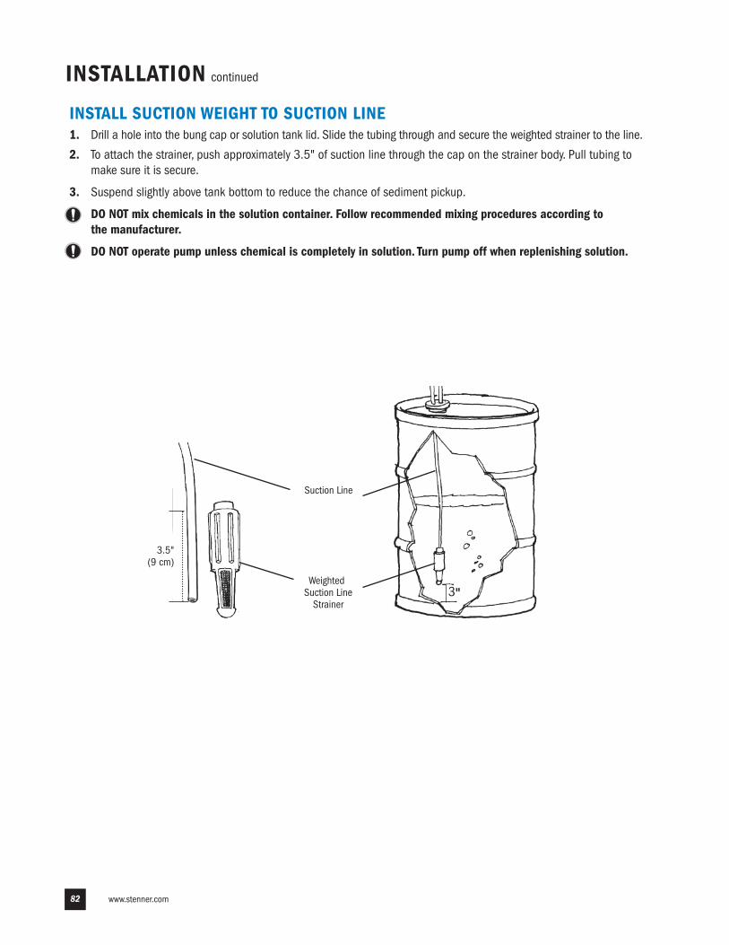
www.stenner.com82
INSTALLATION continued
INSTALL SUCTION WEIGHT TO SUCTION LINE1. Drill a hole into the bung cap or solution tank lid. Slide the tubing through and secure the weighted strainer to the line.
2. To attach the strainer, push approximately 3.5" of suction line through the cap on the strainer body. Pull tubing tomake sure it is secure.
3. Suspend slightly above tank bottom to reduce the chance of sediment pickup.
DO NOT mix chemicals in the solution container. Follow recommended mixing procedures according to the manufacturer.
DO NOT operate pump unless chemical is completely in solution. Turn pump off when replenishing solution.
Suction Line
3.5"(9 cm)
WeightedSuction LineStrainer
3"
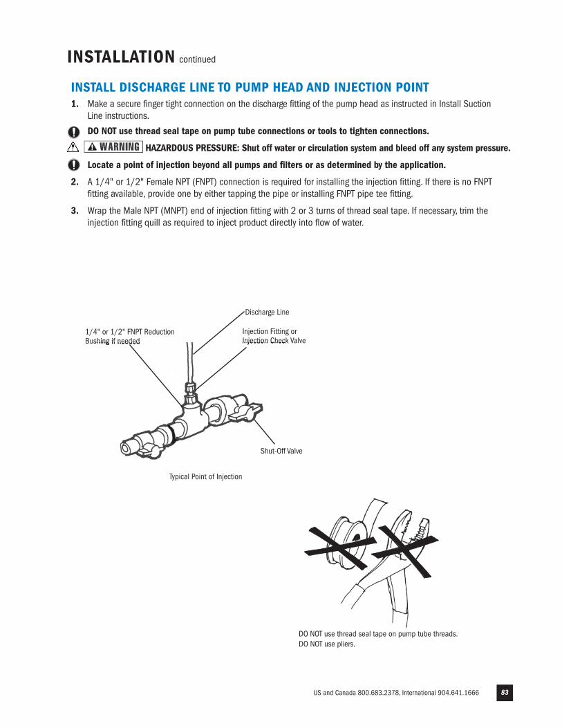
US and Canada 800.683.2378, International 904.641.1666 83
INSTALLATION continued
INSTALL DISCHARGE LINE TO PUMP HEAD AND INJECTION POINT1. Make a secure finger tight connection on the discharge fitting of the pump head as instructed in Install Suction
Line instructions.
DO NOT use thread seal tape on pump tube connections or tools to tighten connections.
HAZARDOUS PRESSURE: Shut off water or circulation system and bleed off any system pressure.
Locate a point of injection beyond all pumps and filters or as determined by the application.
2. A 1/4" or 1/2" Female NPT (FNPT) connection is required for installing the injection fitting. If there is no FNPTfitting available, provide one by either tapping the pipe or installing FNPT pipe tee fitting.
3. Wrap the Male NPT (MNPT) end of injection fitting with 2 or 3 turns of thread seal tape. If necessary, trim theinjection fitting quill as required to inject product directly into flow of water.
1/4" or 1/2" FNPT ReductionBushing if needed
Injection Fitting orInjection Check Valve
Shut-Off Valve
Typical Point of Injection
DO NOT use thread seal tape on pump tube threads.DO NOT use pliers.
Discharge Line
www.stenner.com84
4. Hand tighten the injection fitting into the FNPT fitting.
0-25 psi Model (includes injection fitting)a. Install connecting nut and ferrule to the pump discharge line. Insert discharge line into injection fitting
until it reaches base of fitting.b. Finger tighten connecting nut to fitting.
26-100 psi Model (includes injection check valve)a. Prior to connection, test injection check valve and NPT threads for leaks by pressurizing system.
If necessary, tighten an additional 1/4 turn.b. Install connecting nut and ferrule to the pump discharge line. Insert discharge line into check valve body
until it reaches base of body. c. Finger tighten connecting nut to fitting.
5. Depress and hold the prime button and allow pump to fully prime. The prime button will run the pump and whenreleased the pump will return to automatic mode.
6. Re-pressurize system, observe chemical flow as actuated by system and check all connections for leaks.
7. After suitable amount of dosing time, perform tests for desired chemical readings. If necessary, fine tune dosinglevels by adjusting solution strength.
The injection point and fitting require periodic maintenance to clean any deposits or buildup. To allow quickaccess to the point of injection, Stenner recommends the installation of shut-off valves.
INSTALLATION continued
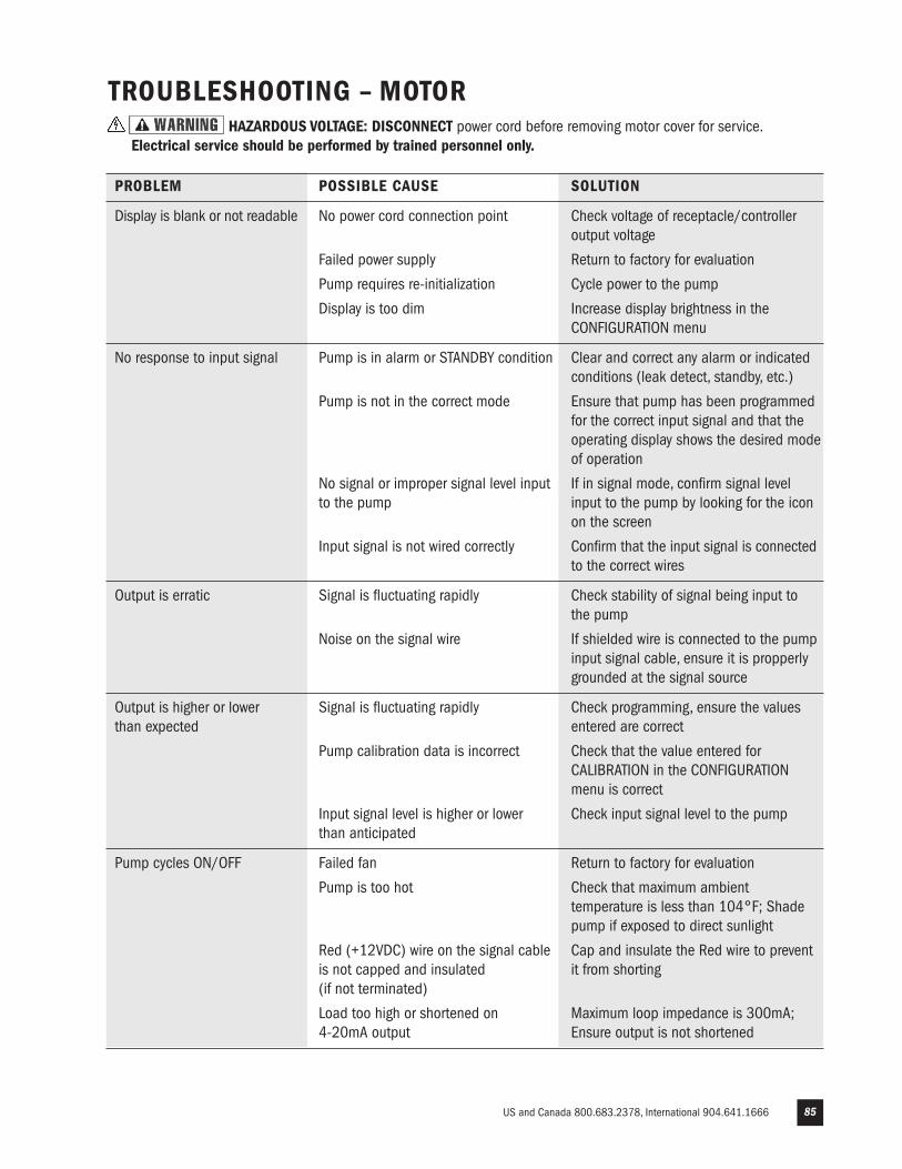
US and Canada 800.683.2378, International 904.641.1666 85
TROUBLESHOOTING – MOTORHAZARDOUS VOLTAGE: DISCONNECT power cord before removing motor cover for service.
Electrical service should be performed by trained personnel only.
PROBLEM POSSIBLE CAUSE SOLUTION
Display is blank or not readable No power cord connection point Check voltage of receptacle/controller output voltage
Failed power supply Return to factory for evaluation
Pump requires re-initialization Cycle power to the pump
Display is too dim Increase display brightness in the CONFIGURATION menu
No response to input signal Pump is in alarm or STANDBY condition Clear and correct any alarm or indicated conditions (leak detect, standby, etc.)
Pump is not in the correct mode Ensure that pump has been programmed for the correct input signal and that the operating display shows the desired mode of operation
No signal or improper signal level input If in signal mode, confirm signal level to the pump input to the pump by looking for the icon on the screen
Input signal is not wired correctly Confirm that the input signal is connected to the correct wires
Output is erratic Signal is fluctuating rapidly Check stability of signal being input to the pump
Noise on the signal wire If shielded wire is connected to the pump input signal cable, ensure it is propperly grounded at the signal source
Output is higher or lower Signal is fluctuating rapidly Check programming, ensure the values than expected entered are correct
Pump calibration data is incorrect Check that the value entered for CALIBRATION in the CONFIGURATION menu is correct
Input signal level is higher or lower Check input signal level to the pump than anticipated
Pump cycles ON/OFF Failed fan Return to factory for evaluation
Pump is too hot Check that maximum ambient temperature is less than 104°F; Shade pump if exposed to direct sunlight
Red (+12VDC) wire on the signal cable Cap and insulate the Red wire to prevent is not capped and insulated it from shorting (if not terminated)
Load too high or shortened on Maximum loop impedance is 300mA; 4-20mA output Ensure output is not shortened
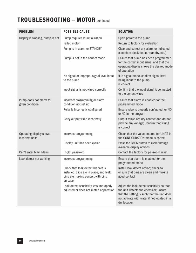
www.stenner.com86
TROUBLESHOOTING – MOTOR continued
PROBLEM POSSIBLE CAUSE SOLUTION
Display is working, pump is not Pump requires re-initialization Cycle power to the pump
Failed motor Return to factory for evaluation
Pump is in alarm or STANDBY Clear and correct any alarm or indicated conditions (leak detect, standby, etc.)
Pump is not in the correct mode Ensure that pump has been programmed for the correct input signal and that the operating display shows the desired mode of operation
No signal or improper signal level input If in signal mode, confirm signal level to the pump being input to the pump is correct
Input signal is not wired correctly Confirm that the input signal is connected to the correct wires
Pump does not alarm for Incorrect programming or alarm Ensure that alarm is enabled for the given condition condition not set up programmed mode
Relay is incorrectly configured Ensure relay is properly configured for NO or NC in the program
Relay output wired incorrectly Output relays are dry contact and do not provide any voltage; Confirm that wiring is correct
Operating display shows Incorrect programming Check that the value entered for UNITS in incorrect units the CONFIGURATION menu is correct
Display unit has been cycled Press the BACK button to cycle through available display options
Can't enter Main Menu Forgot password Contact the factory for password reset
Leak detect not working Incorrect programming Ensure that alarm is enabled for the programmed mode
Check that leak detect bracket is Install leak detect option; check to installed, clips are in place, and leak ensure that pins are clean and making pins are making contact with pins good contact on case
Leak detect sensitivity was improperly Adjust the leak detect sensitivity so that adjusted or does not match application the unit detects the chemical; Ensure that the setting is such that the unit does not activate with water if not located in a dry location
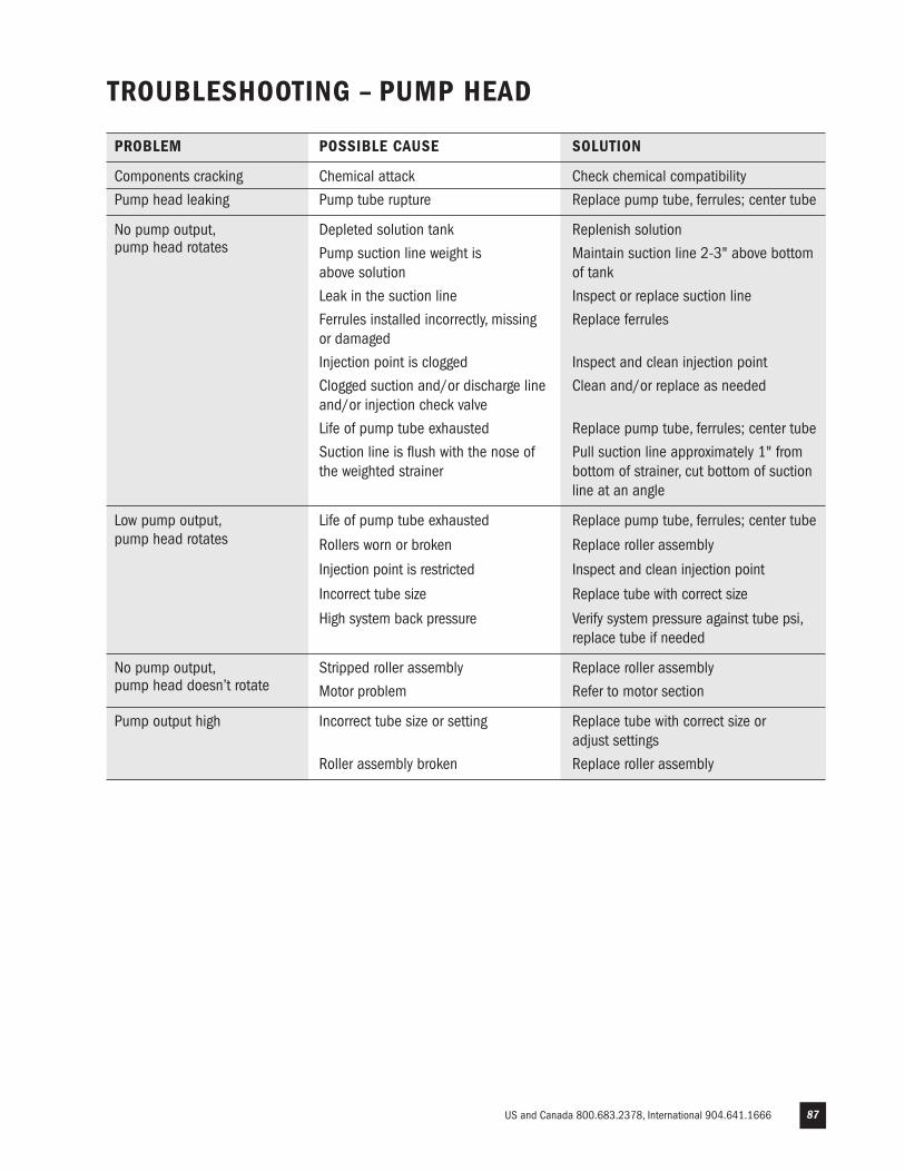
US and Canada 800.683.2378, International 904.641.1666 87
TROUBLESHOOTING – PUMP HEAD
PROBLEM POSSIBLE CAUSE SOLUTION
Components cracking Chemical attack Check chemical compatibility
Pump head leaking Pump tube rupture Replace pump tube, ferrules; center tube
No pump output, Depleted solution tank Replenish solution
pump head rotates Pump suction line weight is Maintain suction line 2-3" above bottom above solution of tank
Leak in the suction line Inspect or replace suction line
Ferrules installed incorrectly, missing Replace ferrules or damaged
Injection point is clogged Inspect and clean injection point
Clogged suction and/or discharge line Clean and/or replace as needed and/or injection check valve
Life of pump tube exhausted Replace pump tube, ferrules; center tube
Suction line is flush with the nose of Pull suction line approximately 1" from the weighted strainer bottom of strainer, cut bottom of suction line at an angle
Low pump output, Life of pump tube exhausted Replace pump tube, ferrules; center tube pump head rotates Rollers worn or broken Replace roller assembly
Injection point is restricted Inspect and clean injection point
Incorrect tube size Replace tube with correct size
High system back pressure Verify system pressure against tube psi, replace tube if needed
No pump output, Stripped roller assembly Replace roller assembly
pump head doesn’t rotate Motor problem Refer to motor section
Pump output high Incorrect tube size or setting Replace tube with correct size or adjust settings
Roller assembly broken Replace roller assembly
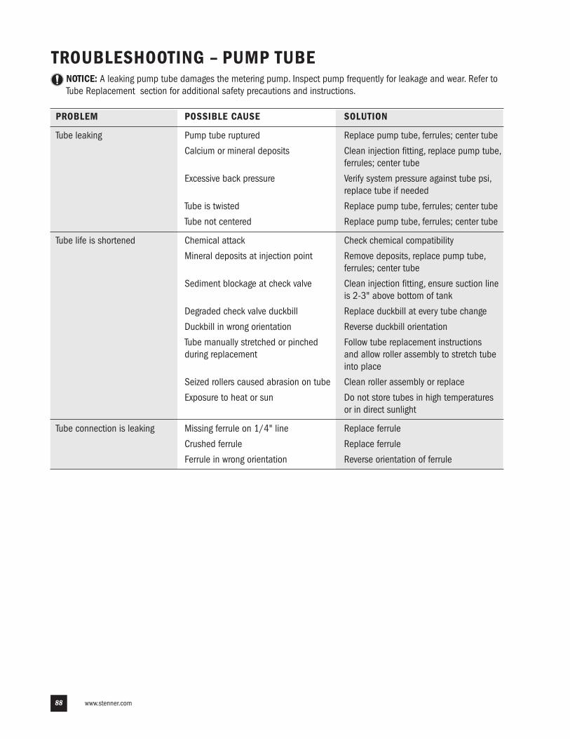
www.stenner.com88
TROUBLESHOOTING – PUMP TUBENOTICE: A leaking pump tube damages the metering pump. Inspect pump frequently for leakage and wear. Refer to
Tube Replacement section for additional safety precautions and instructions.
PROBLEM POSSIBLE CAUSE SOLUTION
Tube leaking Pump tube ruptured Replace pump tube, ferrules; center tube
Calcium or mineral deposits Clean injection fitting, replace pump tube, ferrules; center tube
Excessive back pressure Verify system pressure against tube psi, replace tube if needed
Tube is twisted Replace pump tube, ferrules; center tube
Tube not centered Replace pump tube, ferrules; center tube
Tube life is shortened Chemical attack Check chemical compatibility
Mineral deposits at injection point Remove deposits, replace pump tube, ferrules; center tube
Sediment blockage at check valve Clean injection fitting, ensure suction line is 2-3" above bottom of tank
Degraded check valve duckbill Replace duckbill at every tube change
Duckbill in wrong orientation Reverse duckbill orientation
Tube manually stretched or pinched Follow tube replacement instructions during replacement and allow roller assembly to stretch tube into place
Seized rollers caused abrasion on tube Clean roller assembly or replace
Exposure to heat or sun Do not store tubes in high temperatures or in direct sunlight
Tube connection is leaking Missing ferrule on 1/4" line Replace ferrule
Crushed ferrule Replace ferrule
Ferrule in wrong orientation Reverse orientation of ferrule
US and Canada 800.683.2378, International 904.641.1666 89
TUBE REPLACEMENT – SAFETY INFORMATION
RISK OF CHEMICAL EXPOSURE
To reduce risk of exposure, check the pump tube regularly for leakage. At the first sign of leakage, replace the pump tube.
To reduce risk of exposure, the use of proper personal protective equipment is mandatory when working on or nearchemical metering pumps.
To reduce risk of exposure, and also prior to service, shipping, or storage, pump generous amounts of water or acompatible buffer solution to remove chemical from pump.
Consult chemical manufacturer and MSDS sheet for additional information and precautions for the chemical in use.
Personnel should be skilled and trained in the proper safety and handling of the chemicals in use.
Inspect tube frequently for leakage, deterioration, or wear. Schedule a regular pump tube maintenance change toprevent chemical damage to pump and/or spillage.
PINCH POINT HAZARD
Use extreme caution when replacing pump tube. Be careful of your fingers and do not place fingers near rollers.
HAZARDOUS PRESSURE/CHEMICAL EXPOSURE
Use caution and bleed off all resident system pressure prior to attempting service or installation.
Use caution when disconnecting discharge line from pump. Discharge may be under pressure. Discharge line maycontain chemical.
NOTICE: Indicates special instructions or general mandatory action.
DO NOT apply grease, oil, or lubricants to the pump tube or housing.
Prior to pump tube replacement, inspect the entire pump head for cracks or damaged components. Ensure rollersturn freely.
Rinse off chemical residual and clean all chemical and debris from pump head components prior to tubereplacement. Apply AquaShield™ to main shaft and tube housing cover bushing during tube replacement.
DO NOT pull excessively on pump tube. Avoid kinks or damage during tube installation.
Inspect the suction and discharge lines, injection point (into pipe), and injection check valve duckbill for blockagesafter any tube rupture. Clear or replace as required.
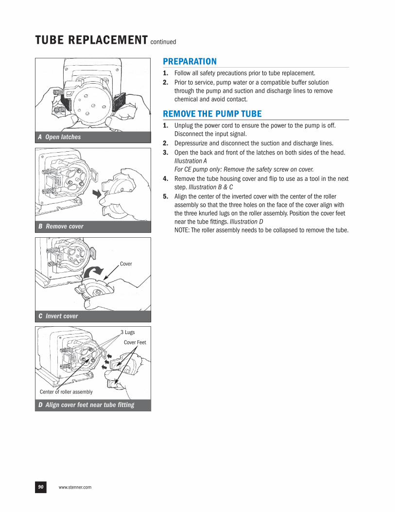
www.stenner.com90
TUBE REPLACEMENT continued
PREPARATION 1. Follow all safety precautions prior to tube replacement.2. Prior to service, pump water or a compatible buffer solution
through the pump and suction and discharge lines to removechemical and avoid contact.
REMOVE THE PUMP TUBE1. Unplug the power cord to ensure the power to the pump is off.
Disconnect the input signal.2. Depressurize and disconnect the suction and discharge lines.3. Open the back and front of the latches on both sides of the head.
Illustration AFor CE pump only: Remove the safety screw on cover.
4. Remove the tube housing cover and flip to use as a tool in the nextstep. Illustration B & C
5. Align the center of the inverted cover with the center of the rollerassembly so that the three holes on the face of the cover align withthe three knurled lugs on the roller assembly. Position the cover feetnear the tube fittings. Illustration DNOTE: The roller assembly needs to be collapsed to remove the tube.
Cover
3 Lugs
Center of roller assembly
A Open latches
B Remove cover
C Invert cover
Cover Feet
D Align cover feet near tube fitting
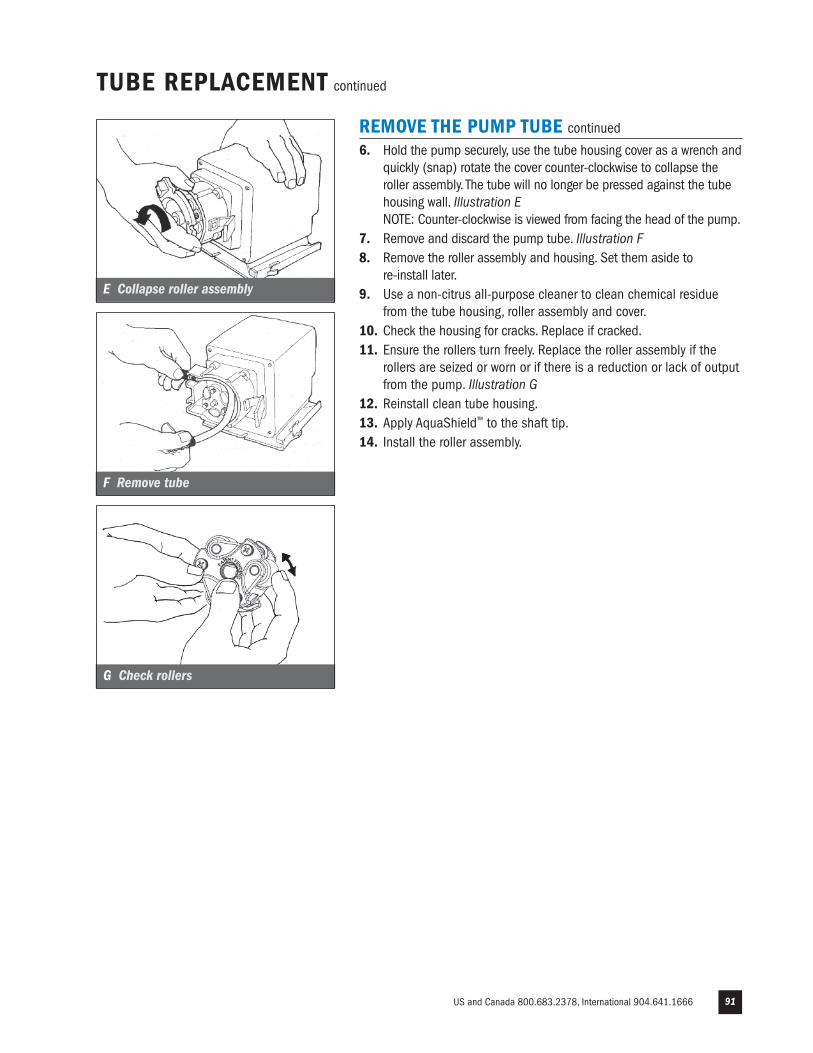
US and Canada 800.683.2378, International 904.641.1666 91
REMOVE THE PUMP TUBE continued
6. Hold the pump securely, use the tube housing cover as a wrench andquickly (snap) rotate the cover counter-clockwise to collapse theroller assembly. The tube will no longer be pressed against the tubehousing wall. Illustration ENOTE: Counter-clockwise is viewed from facing the head of the pump.
7. Remove and discard the pump tube. Illustration F8. Remove the roller assembly and housing. Set them aside to
re-install later.9. Use a non-citrus all-purpose cleaner to clean chemical residue
from the tube housing, roller assembly and cover.10. Check the housing for cracks. Replace if cracked.11. Ensure the rollers turn freely. Replace the roller assembly if the
rollers are seized or worn or if there is a reduction or lack of outputfrom the pump. Illustration G
12. Reinstall clean tube housing.13. Apply AquaShield™ to the shaft tip. 14. Install the roller assembly.
E Collapse roller assembly
F Remove tube
G Check rollers
TUBE REPLACEMENT continued
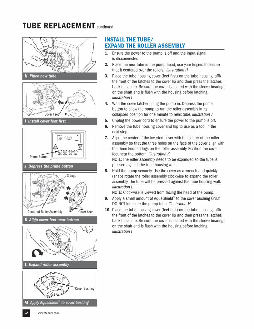
www.stenner.com92
I Install cover feet first
TUBE REPLACEMENT continued
INSTALL THE TUBE/ EXPAND THE ROLLER ASSEMBLY1. Ensure the power to the pump is off and the input signal
is disconnected.2. Place the new tube in the pump head, use your fingers to ensure
that it centered over the rollers. Illustration H3. Place the tube housing cover (feet first) on the tube housing, affix
the front of the latches to the cover lip and then press the latchesback to secure. Be sure the cover is seated with the sleeve bearingon the shaft and is flush with the housing before latching.Illustration I
4. With the cover latched, plug the pump in. Depress the primebutton to allow the pump to run the roller assembly in itscollapsed position for one minute to relax tube. Illustration J
5. Unplug the power cord to ensure the power to the pump is off.6. Remove the tube housing cover and flip to use as a tool in the
next step. 7. Align the center of the inverted cover with the center of the roller
assembly so that the three holes on the face of the cover align withthe three knurled lugs on the roller assembly. Position the coverfeet near the bottom. Illustration KNOTE: The roller assembly needs to be expanded so the tube ispressed against the tube housing wall.
8. Hold the pump securely. Use the cover as a wrench and quickly(snap) rotate the roller assembly clockwise to expand the rollerassembly. The tube will be pressed against the tube housing wall.Illustration LNOTE: Clockwise is viewed from facing the head of the pump.
9. Apply a small amount of AquaShield™ to the cover bushing ONLY.DO NOT lubricate the pump tube. Illustration M
10. Place the tube housing cover (feet first) on the tube housing, affixthe front of the latches to the cover lip and then press the latchesback to secure. Be sure the cover is seated with the sleeve bearingon the shaft and is flush with the housing before latching.Illustration I
K Align cover feet near bottom
Cover Bushing
H Place new tube
L Expand roller assembly
M Apply Aquashield™ to cover bushing
J Depress the prime button
3 Lugs
Center of Roller Assembly Cover Feet
Cover Feet
Prime Button
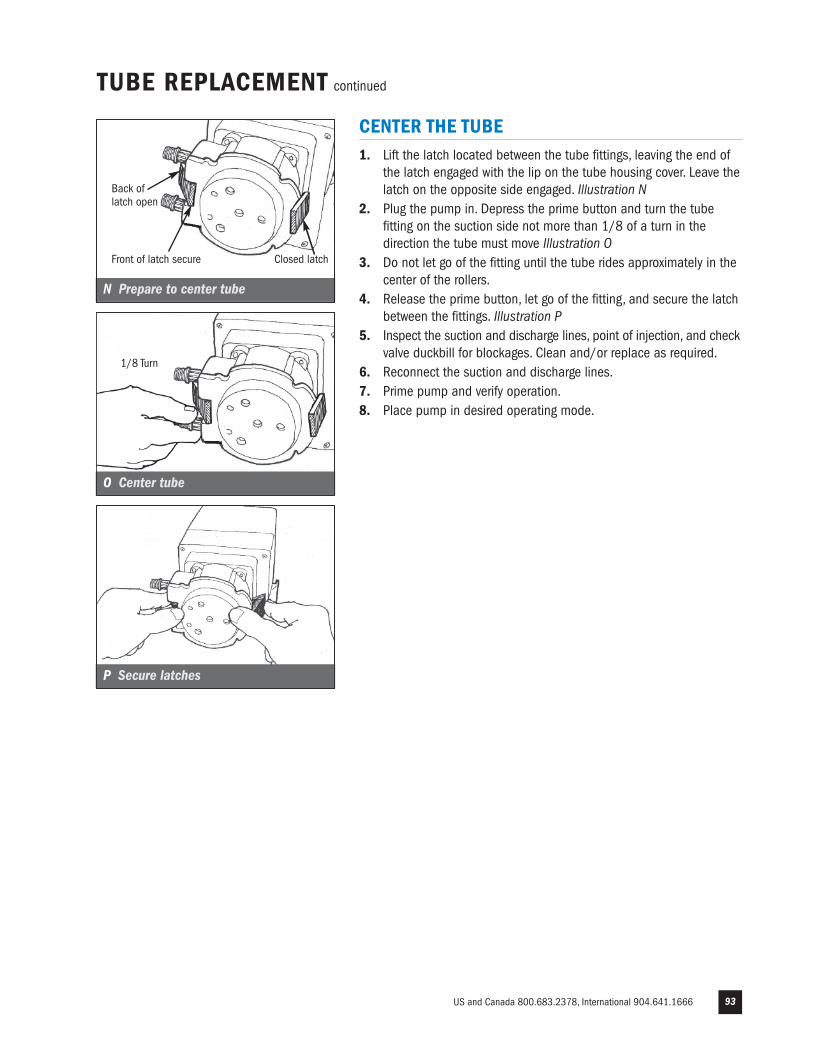
US and Canada 800.683.2378, International 904.641.1666 93
TUBE REPLACEMENT continued
CENTER THE TUBE1. Lift the latch located between the tube fittings, leaving the end of
the latch engaged with the lip on the tube housing cover. Leave thelatch on the opposite side engaged. Illustration N
2. Plug the pump in. Depress the prime button and turn the tubefitting on the suction side not more than 1/8 of a turn in thedirection the tube must move Illustration O
3. Do not let go of the fitting until the tube rides approximately in thecenter of the rollers.
4. Release the prime button, let go of the fitting, and secure the latchbetween the fittings. Illustration P
5. Inspect the suction and discharge lines, point of injection, and checkvalve duckbill for blockages. Clean and/or replace as required.
6. Reconnect the suction and discharge lines. 7. Prime pump and verify operation.8. Place pump in desired operating mode.
N Prepare to center tube
Closed latchFront of latch secure
Back oflatch open
O Center tube
P Secure latches
1/8 Turn
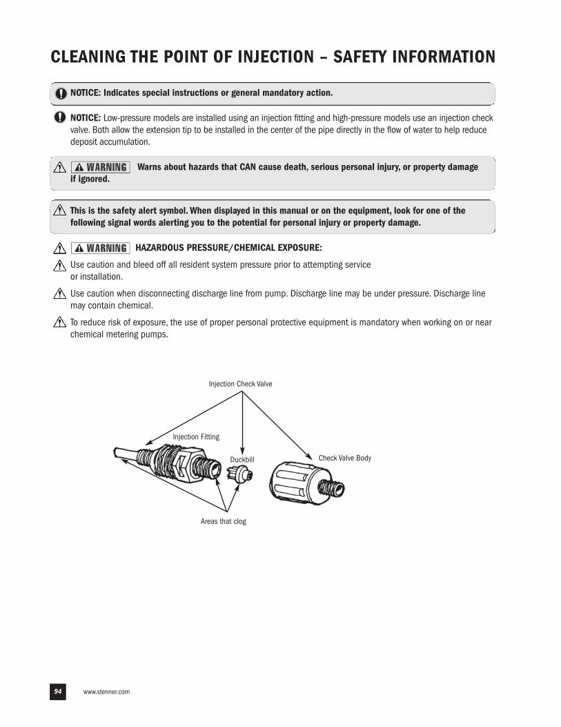
www.stenner.com94
CLEANING THE POINT OF INJECTION – SAFETY INFORMATION
NOTICE: Indicates special instructions or general mandatory action.
NOTICE: Low-pressure models are installed using an injection fitting and high-pressure models use an injection checkvalve. Both allow the extension tip to be installed in the center of the pipe directly in the flow of water to help reducedeposit accumulation.
Warns about hazards that CAN cause death, serious personal injury, or property damage if ignored.
This is the safety alert symbol. When displayed in this manual or on the equipment, look for one of thefollowing signal words alerting you to the potential for personal injury or property damage.
HAZARDOUS PRESSURE/CHEMICAL EXPOSURE:
Use caution and bleed off all resident system pressure prior to attempting service or installation.
Use caution when disconnecting discharge line from pump. Discharge line may be under pressure. Discharge linemay contain chemical.
To reduce risk of exposure, the use of proper personal protective equipment is mandatory when working on or nearchemical metering pumps.
Injection Fitting
Duckbill
Areas that clog
Check Valve Body
Injection Check Valve
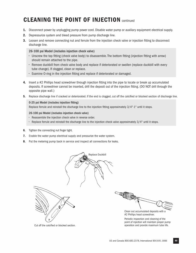
US and Canada 800.683.2378, International 904.641.1666 95
CLEANING THE POINT OF INJECTION continued
1. Disconnect power by unplugging pump power cord. Disable water pump or auxiliary equipment electrical supply.
2. Depressurize system and bleed pressure from pump discharge line.
3. Loosen and remove connecting nut and ferrule from the injection check valve or injection fitting to disconnectdischarge line.
26-100 psi Model (includes injection check valve)• Unscrew the top fitting (check valve body) to disassemble. The bottom fitting (injection fitting with arrow) should remain attached to the pipe.• Remove duckbill from check valve body and replace if deteriorated or swollen (replace duckbill with every tube change). If clogged, clean or replace.• Examine O-ring in the injection fitting and replace if deteriorated or damaged.
4. Insert a #2 Phillips head screwdriver through injection fitting into the pipe to locate or break up accumulateddeposits. If screwdriver cannot be inserted, drill the deposit out of the injection fitting. (DO NOT drill through theopposite pipe wall.)
5. Replace discharge line if cracked or deteriorated. If the end is clogged, cut off the calcified or blocked section of discharge line.
0-25 psi Model (includes injection fitting)Replace ferrule and reinstall the discharge line to the injection fitting approximately 3/4"-1" until it stops.
26-100 psi Model (includes injection check valve)• Reassemble the injection check valve in reverse order.• Replace ferrule and reinstall the discharge line to the injection check valve approximately 3/4" until it stops.
6. Tighten the connecting nut finger tight.
7. Enable the water pump electrical supply and pressurize the water system.
8. Put the metering pump back in service and inspect all connections for leaks.
Replace Duckbill
Clean out accumulated deposits with a #2 Phillips head screwdriver.
Periodic inspection and cleaning of thepoint of injection will maintain proper pumpoperation and provide maximum tube life.Cut off the calcified or blocked section.
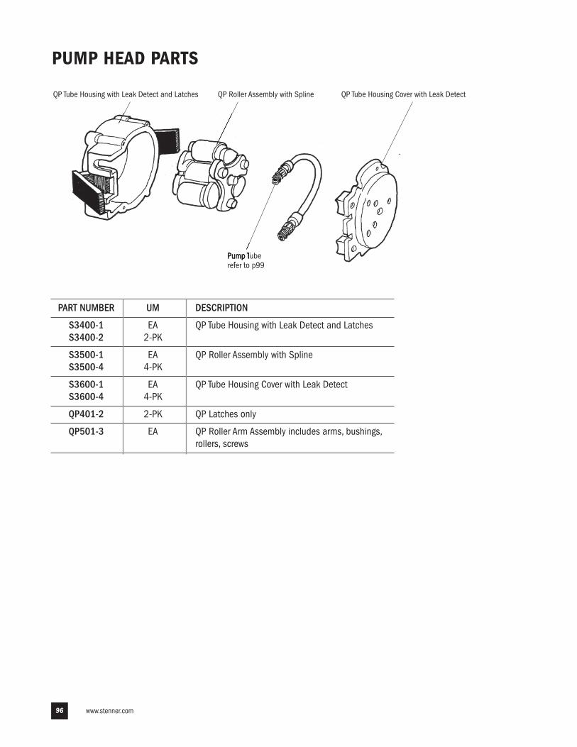
www.stenner.com96
PUMP HEAD PARTS
QP Roller Assembly with SplineQP Tube Housing with Leak Detect and Latches QP Tube Housing Cover with Leak Detect
Pump Tuberefer to p99
PART NUMBER UM DESCRIPTION
S3400-1 EA QP Tube Housing with Leak Detect and LatchesS3400-2 2-PK
S3500-1 EA QP Roller Assembly with SplineS3500-4 4-PK
S3600-1 EA QP Tube Housing Cover with Leak Detect S3600-4 4-PK
QP401-2 2-PK QP Latches only
QP501-3 EA QP Roller Arm Assembly includes arms, bushings, rollers, screws
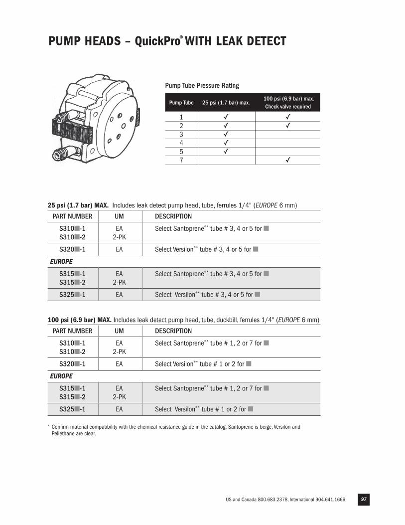
US and Canada 800.683.2378, International 904.641.1666 97
PUMP HEADS – QuickPro® WITH LEAK DETECT
* Confirm material compatibility with the chemical resistance guide in the catalog. Santoprene is beige, Versilon andPellethane are clear.
Pump Tube Pressure Rating
Pump Tube 25 psi (1.7 bar) max.
100 psi (6.9 bar) max. Check valve required
1 ✓ ✓ 2 ✓ ✓ 3 ✓ 4 ✓ 5 ✓ 7 ✓
25 psi (1.7 bar) MAX. Includes leak detect pump head, tube, ferrules 1/4" (EUROPE 6 mm)
PART NUMBER UM DESCRIPTION
S310�-1 EA Select Santoprene®* tube # 3, 4 or 5 for �S310�-2 2-PK
S320�-1 EA Select Versilon®* tube # 3, 4 or 5 for �
EUROPE
S315�-1 EA Select Santoprene®* tube # 3, 4 or 5 for �S315�-2 2-PK
S325�-1 EA Select Versilon®* tube # 3, 4 or 5 for �
100 psi (6.9 bar) MAX. Includes leak detect pump head, tube, duckbill, ferrules 1/4" (EUROPE 6 mm)
PART NUMBER UM DESCRIPTION
S310�-1 EA Select Santoprene®* tube # 1, 2 or 7 for �S310�-2 2-PK
S320�-1 EA Select Versilon®* tube # 1 or 2 for �
EUROPE
S315�-1 EA Select Santoprene®* tube # 1, 2 or 7 for �S315�-2 2-PK
S325�-1 EA Select Versilon®* tube # 1 or 2 for �
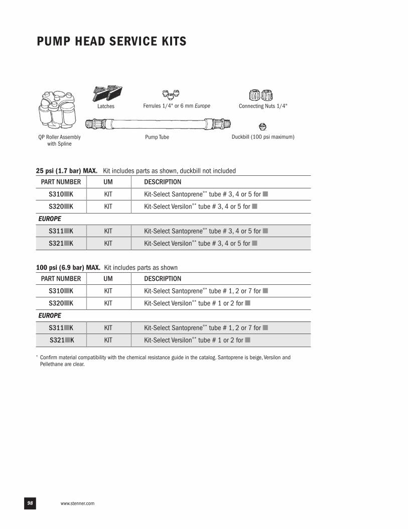
www.stenner.com
PUMP HEAD SERVICE KITS
Pump Tube
Connecting Nuts 1/4"Ferrules 1/4" or 6 mm EuropeLatches
QP Roller Assembly with Spline
Duckbill (100 psi maximum)
* Confirm material compatibility with the chemical resistance guide in the catalog. Santoprene is beige, Versilon andPellethane are clear.
98
25 psi (1.7 bar) MAX. Kit includes parts as shown, duckbill not included
PART NUMBER UM DESCRIPTION
S310�K KIT Kit-Select Santoprene®* tube # 3, 4 or 5 for �
S320�K KIT Kit-Select Versilon®* tube # 3, 4 or 5 for �
EUROPE
S311�K KIT Kit-Select Santoprene®* tube # 3, 4 or 5 for �
S321�K KIT Kit-Select Versilon®* tube # 3, 4 or 5 for �
100 psi (6.9 bar) MAX. Kit includes parts as shown
PART NUMBER UM DESCRIPTION
S310�K KIT Kit-Select Santoprene®* tube # 1, 2 or 7 for �
S320�K KIT Kit-Select Versilon®* tube # 1 or 2 for �
EUROPE
S311�K KIT Kit-Select Santoprene®* tube # 1, 2 or 7 for �
S321�K KIT Kit-Select Versilon®* tube # 1 or 2 for �
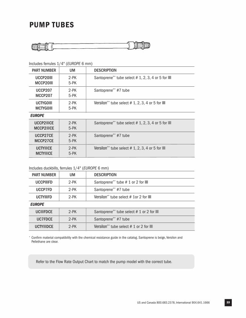
US and Canada 800.683.2378, International 904.641.1666 99
PUMP TUBES
* Confirm material compatibility with the chemical resistance guide in the catalog. Santoprene is beige, Versilon andPellethane are clear.
Includes ferrules 1/4" (EUROPE 6 mm)
PART NUMBER UM DESCRIPTION
UCCP20� 2-PK Santoprene®* tube select # 1, 2, 3, 4 or 5 for �MCCP20� 5-PK
UCCP207 2-PK Santoprene®* #7 tube MCCP207 5-PK
UCTYG0� 2-PK Versilon®* tube select # 1, 2, 3, 4 or 5 for �MCTYG0� 5-PK
EUROPE
UCCP2�CE 2-PK Santoprene®* tube select # 1, 2, 3, 4 or 5 for �MCCP2�CE 5-PK
UCCP27CE 2-PK Santoprene®* #7 tube MCCP27CE 5-PK
UCTY�CE 2-PK Versilon®* tube select # 1, 2, 3, 4 or 5 for �MCTY�CE 5-PK
Includes duckbills, ferrules 1/4" (EUROPE 6 mm)
PART NUMBER UM DESCRIPTION
UCCP�FD 2-PK Santoprene®* tube # 1 or 2 for �
UCCP7FD 2-PK Santoprene®* #7 tube
UCTY�FD 2-PK Versilon®* tube select # 1or 2 for �
EUROPE
UC�FDCE 2-PK Santoprene®* tube select # 1 or 2 for �
UC7FDCE 2-PK Santoprene®* #7 tube
UCTY�DCE 2-PK Versilon®* tube select # 1 or 2 for �
Refer to the Flow Rate Output Chart to match the pump model with the correct tube.
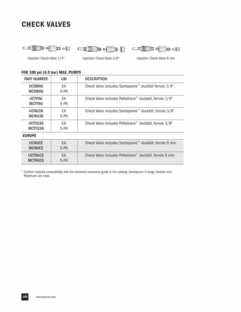
www.stenner.com100
Injection Check Valve 1/4" Injection Check Valve 3/8" Injection Check Valve 6 mm
CHECK VALVES
* Confirm material compatibility with the chemical resistance guide in the catalog. Santoprene is beige, Versilon andPellethane are clear.
FOR 100 psi (6.9 bar) MAX. PUMPS
PART NUMBER UM DESCRIPTION
UCDBINJ EA Check Valve includes Santoprene®* duckbill ferrule 1/4"MCDBINJ 5-PK
UCTYINJ EA Check Valve includes Pellethane®* duckbill, ferrule 1/4"MCTYINJ 5-PK
UCINJ38 EA Check Valve includes Santoprene®* duckbill, ferrule 3/8"MCINJ38 5-PK
UCTYIJ38 EA Check Valve includes Pellethane®* duckbill, ferrule 3/8"MCTYIJ38 5-PK
EUROPE
UCINJCE EA Check Valve includes Santoprene®* duckbill, ferrule 6 mmMCINJCE 5-PK
UCTINJCE EA Check Valve includes Pellethane®* duckbill, ferrule 6 mmMCTINJCE 5-PK
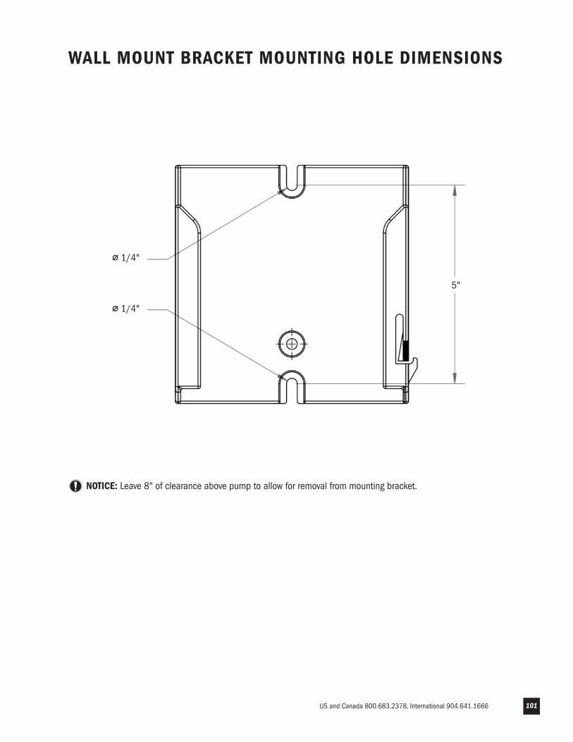
US and Canada 800.683.2378, International 904.641.1666 101
NOTICE: Leave 8" of clearance above pump to allow for removal from mounting bracket.
WALL MOUNT BRACKET MOUNTING HOLE DIMENSIONS
⌀ 1/4"
⌀ 1/4"
5"

IMS 070617
STENNER PUMP COMPANY
3174 DeSalvo RoadJacksonville, Florida 32246USA
Phone: 904.641.1666US Toll Free: 800.683.2378Fax: 904.642.1012
Hours of Operation (EST):Mon.–Thu. 7:30 am–5:30 pmFri. 7:00 am–5:30 pm
Assembled in the USA
© Stenner Pump Company All Rights Reserved