Embed Size (px)
Citation preview
- -
INSTALLATION AND MAINTENANCE MANUAL
Version 2014.1
ROLLER BED BELT CONVEYOR
MODEL BR100C & BRI
- 2 -
ROLLER BED STRAIGHT AND INCLINE BELT CONVEYOR INSTALLATION AND MAINTENANCE MANUAL
TABLE OF CONTENTS
INTRODUCTION Receiving, Inspection and Uncrating .................................................................................................. 3 Ordering Replacement Parts .............................................................................................................. 3
SAFETY INFORMATION Installation .......................................................................................................................................... 4 Operation ........................................................................................................................................... 4-5 Maintenance ...................................................................................................................................... 5 Electrical ............................................................................................................................................. 6
INSTALLATION Floor Support Installation ................................................................................................................... 7 Ceiling Hanger Installation ................................................................................................................. 7 Conveyor Set-Up ................................................................................................................................ 8 Belt Installation ................................................................................................................................... 9 Racked Sections ................................................................................................................................ 10
OPERATION Start-Up Overview .............................................................................................................................. 11
BELT TRACKING Prior to Tracking ................................................................................................................................. 12 End Drive ............................................................................................................................................ 12 Center Drive (Forward Service) ......................................................................................................... 13 Center Drive (Reverse Service) ......................................................................................................... 13 Belt Tracking Diagram ........................................................................................................................ 14 MAINTENANCE Lubrication .......................................................................................................................................... 15 Chain Alignment and Tensioning ....................................................................................................... 15 Maintenance Schedule ....................................................................................................................... 16 Trouble Shooting ................................................................................................................................ 17
REPLACEMENT PARTS Parts Drawing and List 8” End Drive ....................................................................................................................................... 18 8” End Drive Assembly ................................................................................................................ 19-20 8” Center Drive ................................................................................................................................... 21 8” Center Drive Assembly ............................................................................................................ 22 6” Underside Take-Up .................................................................................................................. 23 BRI Conveyor ..................................................................................................................................... 24-25 BRI Power Feeder .............................................................................................................................. 26-27 Under Trussing ................................................................................................................................... 28
- 3 -
This manual has been created to assist with the maintenance, operation and installation of the BR100C and BRI
conveyor. It is important that all maintenance personnel are trained properly in operation and maintenance of the
conveyor. Damage or injury caused by non-compliance with this manual is not the responsibility of Atlantis Technologies
LLC.
RECEIVING, INSPECTION AND UNCRATING
1) Compare the bill of lading with what you have received.
2) Examine the equipment for damage during shipping.
3) Immediately report shortage or damages to the carrier.
4) Move all crates to area of installation.
5) Remove crating and packaging.
6) Look for boxes, accessories, bags or components such as fasteners, manuals, guard rails, etc. that may be banded
or fastened to the crating material to ensure you do not discard any loose parts (Guards, Fasteners or other
components) that were packaged for loose shipping.
ORDERING REPLACEMENT PARTS
Assembly drawings with replacement parts listings have been provided in this manual.
Procedure for ordering replacement parts:
1) Contact your Atlantis Technologies LLC Distributor.
2) Give Conveyor Model Number and/or Serial Number.
3) Give Part Number and complete description from Parts Listing.
4) Give type of drive configuration. For instance: 8” End Drive, 8” Center Drive, etc.
5) Tell us if you are in a breakdown situation.
ROLLER BED STRAIGHT AND INCLINE BELT CONVEYOR INSTALLATION AND MAINTENANCE MANUAL
INTRODUCTION
- 4 -
GUARDS AND GUARDING
Interfacing of Equipment
When two or more pieces of equipment are interfaced, special attention should be given to the interfaced area to ensure
the presence of adequate guarding and safety devices.
Guarding Exceptions
Wherever conditions prevail that would require guarding under this standard but such guarding would render the
conveyor unusable, seek guidance from your safety professional.
Overhead conveyors for which guarding would render the conveyor unusable or would be impracticable, should have
prominent and legible warnings posted in the area or on the equipment and where feasible lines should be painted on
the floor delineating the danger area.
When a conveyor passes over a walkway, roadway or work station, it is considered guarded by location if all moving
parts are at least 2.44 meters (8 feet) above the floor or walking surface or are otherwise located so that personnel
cannot inadvertently come in contact with hazardous moving parts. Check your state and local laws and codes for overall
compliance.
Although overhead conveyors may be guarded by location, spill guards, pan guard or equivalent should be installed if
material may fall off the conveyor and endanger personnel.
HEADROOM CLEARANCE
When conveyors are installed above exit passageways, aisles or corridors, there should be provided a minimum
clearance of 2.00 meters (6 feet 8 inches) measured vertically from the floor or walking surface to the lowest part of the
conveyor or guards.
Where system function will be impaired by providing the minimum clearance of 2.00 meters (6 feet 8 inches) through an
emergency exit, alternate passageways should be provided.
It is permissible to allow passage under conveyors with less than 2.00 meters (6 feet 8 inches) clearance from the floor
for other than emergency exits if a suitable warning indicates low headroom. Check your state and local laws and codes
for overall compliance.
ROLLER BED STRAIGHT AND INCLINE BELT CONVEYOR INSTALLATION AND MAINTENANCE MANUAL
SAFETY INFORMATION - INSTALLATION
Only trained, qualified personnel should be permitted to operate a conveyor. Training should include instruction in
operation under normal conditions and emergency situations.
Where safety is dependent upon stopping / starting devices, they should be kept free of obstructions to permit access.
The area around loading and unloading points should be kept clear of obstructions that could endanger personnel.
Do not ride the load-carrying element of a conveyor under any circumstances. Warning labels reading “DO NOT RIDE
CONVEYOR” should be affixed by the manufacturer of the conveyor.
Personnel working on or near a conveyor should be instructed as to the location and operation of pertinent stopping
devices.
A conveyor should be used to transport only a load that it is designed to be handle safely.
Under no circumstances should the safety characteristics of the conveyor be altered.
SAFETY INFORMATION - OPERATION
- 5 -
Routine inspections and preventative and corrective maintenance programs should be conducted to ensure that all
safety features and guards are retained and functioning properly. Inspect equipment for safety labels. Make sure
personnel are aware of and follow safety label instructions.
Alert all personnel to the potential hazard of entanglement in conveyors caused by items such as long hair, loose
clothing and jewelry.
ROLLER BED STRAIGHT AND INCLINE BELT CONVEYOR INSTALLATION AND MAINTENANCE MANUAL
SAFETY INFORMATION - OPERATION (Continued)
Maintenance and service should be performed by trained, qualified personnel only.
Where lack of maintenance and service would cause a hazardous condition, the user should establish a maintenance
program to ensure that conveyor components are maintained in a condition that does not constitute a hazard to
personnel.
ADJUSTMENTS OR MAINTENANCE/SERVICE DURING OPERATION
Conveyors should NOT be maintained or serviced while in operation.
When a conveyor is stopped for maintenance or service, the starting devices, prime mover, powered accessories or
electrical must be locked / tagged out in accordance with your company machine specific formalized procedure designed
to protect all persons or groups involved with the conveyor against an unexpected restart. Personnel should be alerted to
the hazard of stored energy, which may exist after the power source is locked/tagged out. All safety devices and guards
should be replaced before starting equipment for normal operation.
GUARDS AND SAFETY DEVICES
Guards and safety devices should be maintained in a serviceable and operational condition. Warning signs are the
responsibility of the owner of the conveyor and should be maintained in a legible / operational condition.
LUBRICATION
Conveyors should NOT be lubricated while in operation.
Where the drip of lubricants or process liquids on the floor constitutes a hazard, drip pans or other means of eliminating
the hazard must be provided by purchaser(s).
ROLLER BED STRAIGHT AND INCLINE BELT CONVEYOR INSTALLATION AND MAINTENANCE MANUAL
SAFETY INFORMATION - MAINTENANCE
ATTENTION: ELECTRICAL POWER MUST BE TURNED OFF AND LOCKED / TAGGED OUT following your
company’s machine specific procedures when servicing the conveyor to prevent accidental restarting by other
persons or interconnecting equipment.
- 6 -
ELECTRICAL CODE
All electrical installations and wiring should conform to federal, state and local codes.
When conveyor operation is not required for a maintenance procedure, electrical power must be turned off and locked /
tagged out following your company’s machine specific procedure.
CONTROL STATIONS
Control stations should be so arranged and located that the operation of the affected equipment is visible from them.
Control stations should be clearly marked or labeled to indicate the function controlled.
A conveyor that would cause injury when started should not be started until personnel in the area are alerted by a signal
or by a designated person that the conveyor is about to start.
Where system function would be seriously hindered or adversely affected by the required time delay or where the intent
of the warning may be misinterpreted (i.e., a work area with many different conveyors and associated devices), a clear,
concise and legible warning sign needs to be provided. The warning sign should indicate that conveyors and associated
equipment may be started at any time, that danger exists and that personnel must keep clear. These warning signs
should be provided along the conveyor at areas not guarded by position or location.
Remotely and automatically controlled conveyors, and conveyors where operator stations are not manned or are beyond
voice or visual contact from drive areas, loading areas, transfer points and other potentially hazardous locations on the
conveyor path not guarded by location, position or guards should be furnished with emergency stop buttons, pull cords,
limit switches or similar emergency stop devices.
All such emergency stop devices should be easily identifiable in the immediate vicinity of such locations unless guarded
by location, position or guards. Where the design, function and operation of such conveyor clearly is not hazardous to
personnel, an emergency stop device is not required.
The emergency stop device should act directly on the control of the conveyor concerned and should not depend on the
stopping of any other equipment. The emergency stop devices should be installed so that they cannot be overridden
from other locations.
Inactive and unused actuators, controllers and wiring should be removed from control stations and panel board, together
with obsolete diagrams, indicators, control labels and other material that might confuse the operator.
SAFETY DEVICES
All safety devices, including wiring of electrical safety devices, should be arranged to operate such that a power failure or
failure of the device itself will not result in a hazardous condition.
Conveyor controls should be so arranged that, in case of emergency stop, manual reset or start at the location where the
emergency stop was initiated should be required for the conveyor(s) and associated equipment to resume operation.
Before restarting a conveyor that has been stopped because of an emergency, an inspection of the conveyor should be
made and the cause of the stoppage determined. The starting device and electrical power must be turned off and
locked / tagged out according to your company’s machine specific procedure before any attempt is made to remove the
cause of the stoppage, unless operation is necessary to determine the cause or to safely remove the stoppage.
Replace all safety devices, guards and guarding prior to equipment start-up.
ROLLER BED STRAIGHT AND INCLINE BELT CONVEYOR INSTALLATION AND MAINTENANCE MANUAL
SAFETY INFORMATION - ELECTRICAL
- 7 -
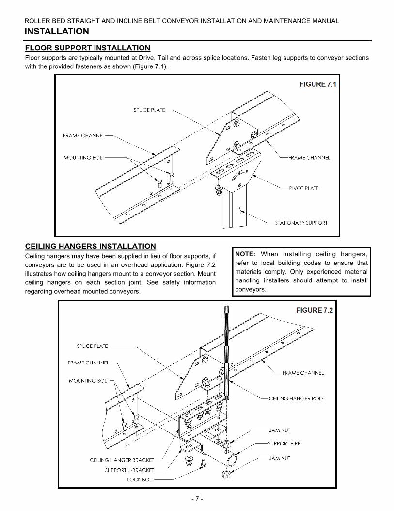
FLOOR SUPPORT INSTALLATION
Floor supports are typically mounted at Drive, Tail and across splice locations. Fasten leg supports to conveyor sections
with the provided fasteners as shown (Figure 7.1).
ROLLER BED STRAIGHT AND INCLINE BELT CONVEYOR INSTALLATION AND MAINTENANCE MANUAL
INSTALLATION
CEILING HANGERS INSTALLATION
Ceiling hangers may have been supplied in lieu of floor supports, if
conveyors are to be used in an overhead application. Figure 7.2
illustrates how ceiling hangers mount to a conveyor section. Mount
ceiling hangers on each section joint. See safety information
regarding overhead mounted conveyors.
NOTE: When installing ceiling hangers,
refer to local building codes to ensure that
materials comply. Only experienced material
handling installers should attempt to install
conveyors.
- 8 -
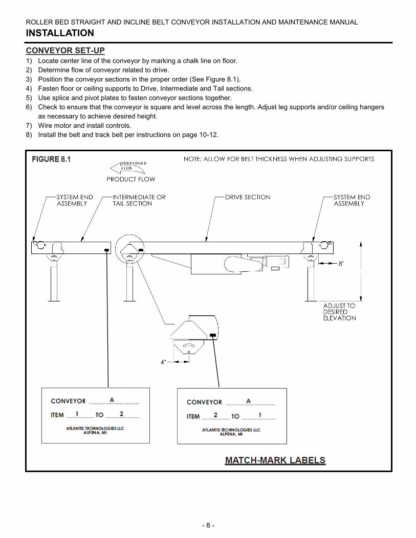
CONVEYOR SET-UP
1) Locate center line of the conveyor by marking a chalk line on floor.
2) Determine flow of conveyor related to drive.
3) Position the conveyor sections in the proper order (See Figure 8.1).
4) Fasten floor or ceiling supports to Drive, Intermediate and Tail sections.
5) Use splice and pivot plates to fasten conveyor sections together.
6) Check to ensure that the conveyor is square and level across the length. Adjust leg supports and/or ceiling hangers
as necessary to achieve desired height.
7) Wire motor and install controls.
8) Install the belt and track belt per instructions on page 10-12.
ROLLER BED STRAIGHT AND INCLINE BELT CONVEYOR INSTALLATION AND MAINTENANCE MANUAL
INSTALLATION
- 9 -
ROLLER BED STRAIGHT AND INCLINE BELT CONVEYOR INSTALLATION AND MAINTENANCE MANUAL
INSTALLATION
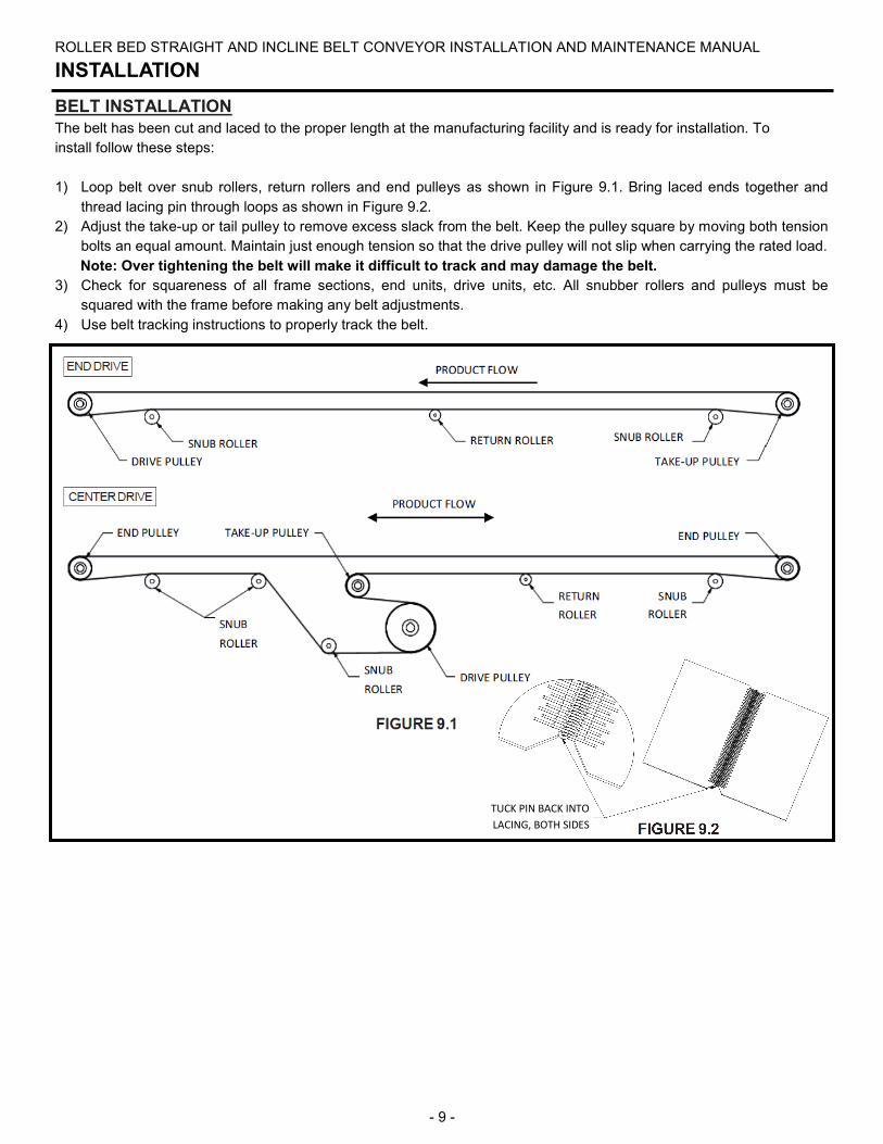
BELT INSTALLATION
The belt has been cut and laced to the proper length at the manufacturing facility and is ready for installation. To
install follow these steps:
1) Loop belt over snub rollers, return rollers and end pulleys as shown in Figure 9.1. Bring laced ends together and
thread lacing pin through loops as shown in Figure 9.2.
2) Adjust the take-up or tail pulley to remove excess slack from the belt. Keep the pulley square by moving both tension
bolts an equal amount. Maintain just enough tension so that the drive pulley will not slip when carrying the rated load.
Note: Over tightening the belt will make it difficult to track and may damage the belt.
3) Check for squareness of all frame sections, end units, drive units, etc. All snubber rollers and pulleys must be
squared with the frame before making any belt adjustments.
4) Use belt tracking instructions to properly track the belt.
TUCK PIN BACK INTO
LACING, BOTH SIDES
- 10 -
ROLLER BED STRAIGHT AND INCLINE BELT CONVEYOR INSTALLATION AND MAINTENANCE MANUAL
INSTALLATION
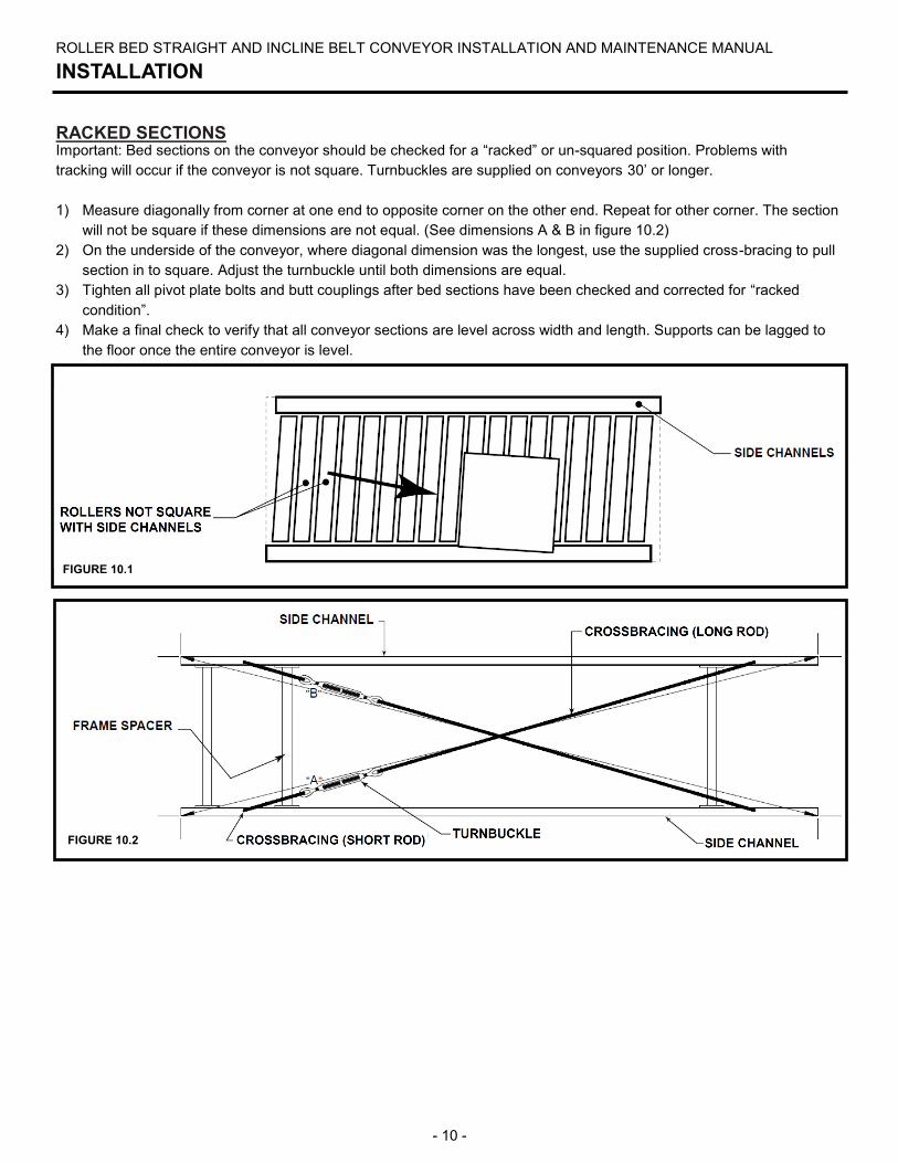
RACKED SECTIONS Important: Bed sections on the conveyor should be checked for a “racked” or un-squared position. Problems with
tracking will occur if the conveyor is not square. Turnbuckles are supplied on conveyors 30’ or longer.
1) Measure diagonally from corner at one end to opposite corner on the other end. Repeat for other corner. The section
will not be square if these dimensions are not equal. (See dimensions A & B in figure 10.2)
2) On the underside of the conveyor, where diagonal dimension was the longest, use the supplied cross-bracing to pull
section in to square. Adjust the turnbuckle until both dimensions are equal.
3) Tighten all pivot plate bolts and butt couplings after bed sections have been checked and corrected for “racked
condition”.
4) Make a final check to verify that all conveyor sections are level across width and length. Supports can be lagged to
the floor once the entire conveyor is level.
FIGURE 10.1
FIGURE 10.2
- 11 -
ROLLER BED STRAIGHT AND INCLINE BELT CONVEYOR INSTALLATION AND MAINTENANCE MANUAL
OPERATION
START-UP OVERVIEW
1) Ensure that conveyor sections, leg supports, etc. were installed properly.
2) Ensure that drive chains and sprockets are installed, aligned and tensioned properly.
3) Ensure set screws are tight in sprockets, bearings and pulleys.
4) Ensure that all drive, mounted bearings and fasteners are securely tighten.
5) Ensure that all motor and control wiring is connected properly.
6) Ensure that the conveyor is not loaded with product.
7) Ensure that gearboxes are properly filled with the correct amount of lubricant or that they were factory filled with
lubricant.
8) Ensure that the gearbox has necessary vent plugs installed (if applicable).
- 12 -
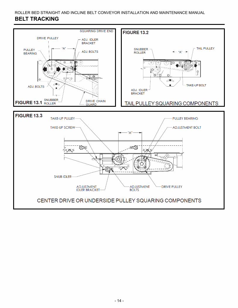
The belt is tracked by adjusting snub rollers, return rollers, tail pulley and drive pulley. The initial goal is to center the belt on pulley at infeed end of conveyor, then move to discharge end if needed. All adjustments should be made in small increments (1/16 in. at a time). Allow adequate time for the belt to react to each adjustment. It may take several complete belt revolutions to see the effect of each adjustment. CONVEYOR POWER MUST BE TURNED OFF WHEN MAKE ANY ADJUSTMENTS. The same tracking principles apply to conveyors supplied with end drives, center drives or underside take-ups.
PRIOR TO TRACKING 1) Make sure conveyor frame is cross square.
2) Confirm that conveyor is level across its width and length.
3) Make sure snubber rollers, return rollers, tail pulley and drive pulley are square with the frame.
Reference dimension “A” in figures 13.1, 13.2 and 13.3.
4) Confirm belt has been properly threaded through the conveyor.
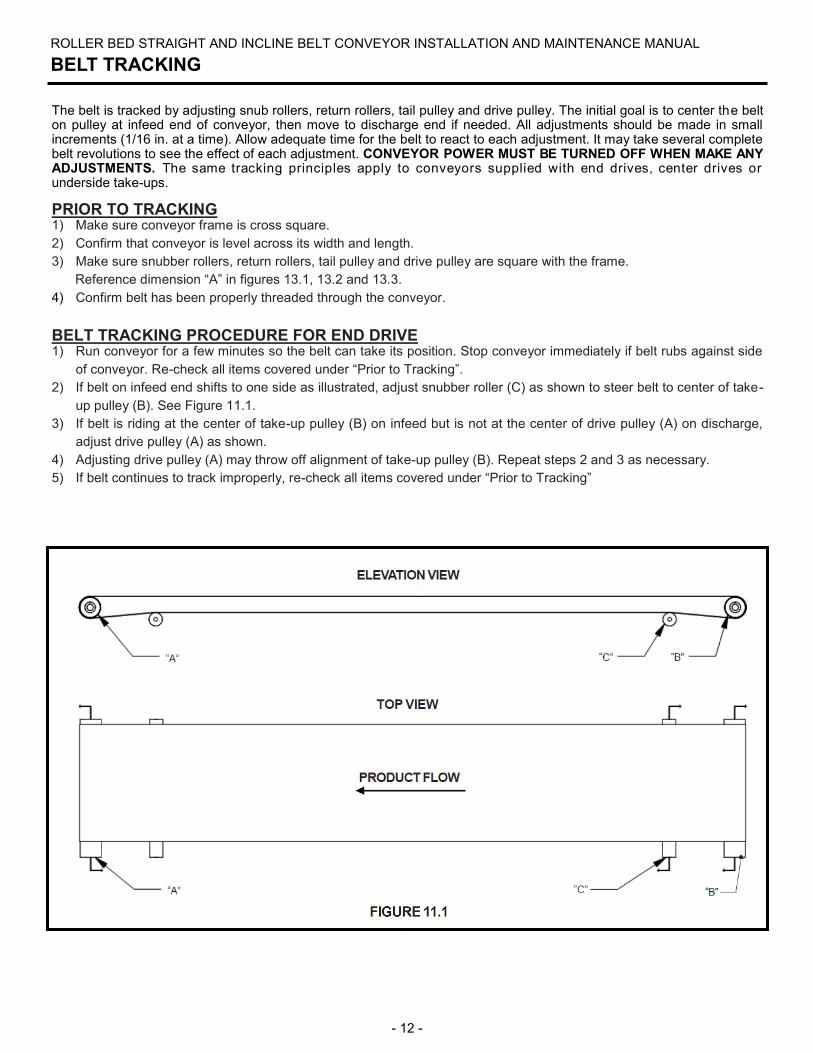
BELT TRACKING PROCEDURE FOR END DRIVE 1) Run conveyor for a few minutes so the belt can take its position. Stop conveyor immediately if belt rubs against side
of conveyor. Re-check all items covered under “Prior to Tracking”.
2) If belt on infeed end shifts to one side as illustrated, adjust snubber roller (C) as shown to steer belt to center of take-
up pulley (B). See Figure 11.1.
3) If belt is riding at the center of take-up pulley (B) on infeed but is not at the center of drive pulley (A) on discharge,
adjust drive pulley (A) as shown.
4) Adjusting drive pulley (A) may throw off alignment of take-up pulley (B). Repeat steps 2 and 3 as necessary.
5) If belt continues to track improperly, re-check all items covered under “Prior to Tracking”
ROLLER BED STRAIGHT AND INCLINE BELT CONVEYOR INSTALLATION AND MAINTENANCE MANUAL
BELT TRACKING
- 13 -
ROLLER BED STRAIGHT AND INCLINE BELT CONVEYOR INSTALLATION AND MAINTENANCE MANUAL
BELT TRACKING
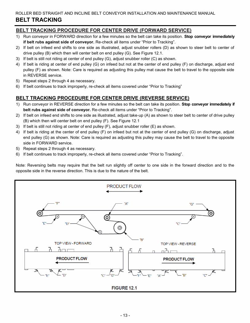
BELT TRACKING PROCEDURE FOR CENTER DRIVE (FORWARD SERVICE)
1) Run conveyor in FORWARD direction for a few minutes so the belt can take its position. Stop conveyor immediately
if belt rubs against side of conveyor. Re-check all items under “Prior to Tracking”.
2) If belt on infeed end shifts to one side as illustrated, adjust snubber rollers (D) as shown to steer belt to center of
drive pulley (B) which then will center belt on end pulley (G). See Figure 12.1.
3) If belt is still not riding at center of end pulley (G), adjust snubber roller (C) as shown.
4) If belt is riding at center of end pulley (G) on infeed but not at the center of end pulley (F) on discharge, adjust end
pulley (F) as shown. Note: Care is required as adjusting this pulley mat cause the belt to travel to the opposite side
in REVERSE service.
5) Repeat steps 2 through 4 as necessary.
6) If belt continues to track improperly, re-check all items covered under “Prior to Tracking”
BELT TRACKING PROCEDURE FOR CENTER DRIVE (REVERSE SERVICE)
1) Run conveyor in REVERSE direction for a few minutes so the belt can take its position. Stop conveyor immediately if
belt rubs against side of conveyor. Re-check all items under “Prior to Tracking”.
2) If belt on infeed end shifts to one side as illustrated, adjust take-up (A) as shown to steer belt to center of drive pulley
(B) which then will center belt on end pulley (F). See Figure 12.1
3) If belt is still not riding at center of end pulley (F), adjust snubber roller (E) as shown.
4) If belt is riding at the center of end pulley (F) on infeed but not at the center of end pulley (G) on discharge, adjust
end pulley (G) as shown. Note: Care is required as adjusting this pulley may cause the belt to travel to the opposite
side in FORWARD service.
5) Repeat steps 2 through 4 as necessary.
6) If belt continues to track improperly, re-check all items covered under “Prior to Tracking”.
Note: Reversing belts may require that the belt run slightly off center to one side in the forward direction and to the
opposite side in the reverse direction. This is due to the nature of the belt.
- 14 -
ROLLER BED STRAIGHT AND INCLINE BELT CONVEYOR INSTALLATION AND MAINTENANCE MANUAL
BELT TRACKING
- 15 -
ROLLER BED STRAIGHT AND INCLINE BELT CONVEYOR INSTALLATION AND MAINTENANCE MANUAL
MAINTENANCE
LUBRICATION
Chain Lubrication
Proper maintenance of any chain should include correct lubrication, periodic inspection and proper adjustment for normal
wear. Periodic inspection of the chain and sprockets is required to detect any deviation from normal wear before serious
damage takes place. The cost of such inspection is repaid in an extended chain life. No general rule can be given for the
frequency of inspection. The frequency should be influenced by conditions of operation.
Suggested Lubrication
Only high quality oil should be used to lubricate chain. Neither heavy oil nor grease is suitable. A lubricant with the
proper viscosity enables it to reach internal surfaces under normal conditions. Lubricants suggested for specific ambient
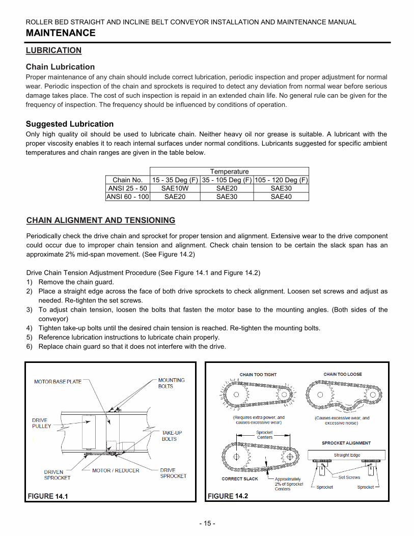
temperatures and chain ranges are given in the table below.
CHAIN ALIGNMENT AND TENSIONING
Periodically check the drive chain and sprocket for proper tension and alignment. Extensive wear to the drive component
could occur due to improper chain tension and alignment. Check chain tension to be certain the slack span has an
approximate 2% mid-span movement. (See Figure 14.2)
Drive Chain Tension Adjustment Procedure (See Figure 14.1 and Figure 14.2)
1) Remove the chain guard.
2) Place a straight edge across the face of both drive sprockets to check alignment. Loosen set screws and adjust as
needed. Re-tighten the set screws.
3) To adjust chain tension, loosen the bolts that fasten the motor base to the mounting angles. (Both sides of the
conveyor)
4) Tighten take-up bolts until the desired chain tension is reached. Re-tighten the mounting bolts.
5) Reference lubrication instructions to lubricate chain properly.
6) Replace chain guard so that it does not interfere with the drive.
Temperature
Chain No. 15 - 35 Deg (F) 35 - 105 Deg (F) 105 - 120 Deg (F)
ANSI 25 - 50 SAE10W SAE20 SAE30
ANSI 60 - 100 SAE20 SAE30 SAE40
14.2 14.1
- 16 -
ROLLER BED STRAIGHT AND INCLINE BELT CONVEYOR INSTALLATION AND MAINTENANCE MANUAL
MAINTENANCE SCHEDULE
DAILY MAINTENANCE
Inspect all conveyors to ensure that all guarding is securely in place.
Inspect belt tracking for a minimum of (3) full belt revolutions.
WEEKLY MAINTENANCE
Inspect conveyor for loose bolts and set screws.
Inspect bearings, gear reducers, motors and chains for excessive noise or heat.
Inspect belt to ensure that there is not excessive wear and that all splices are intact.
Inspect belt tension. The tension should be enough to:
Prevent slippage between drive pulley (sheaves for spurs) and belt under a full load.
Force belt to conform to the crown on crowned pulleys.
Inspect rollers to ensure that they rotate freely without excessive noise.
MONTHLY MAINTENANCE
Inspect oil level in reducer. Fill if necessary.
Inspect reducer for leaking seals.
Inspect conveyor for loose bolts.
Inspect drive chains, jump chains and sprockets for wear, alignment and proper chain tension.
Lubricate pulley shaft bearings. Use No. 2 lithium base grease or equivalent.
QUARTERLY MAINTENANCE
Grease all pulley shaft bearings.
Inspect conveyors for worn or broken drive belts. Replace as necessary. If belt shows signs of abrasion, check for
hindrance with the belt or foreign object in the roller groove.
SEMI-ANNUAL MAINTENANCE
Tighten all bearing set screws if not completely tight.
ANNUAL MAINTENANCE
Change oil in reducers.
- 17 -
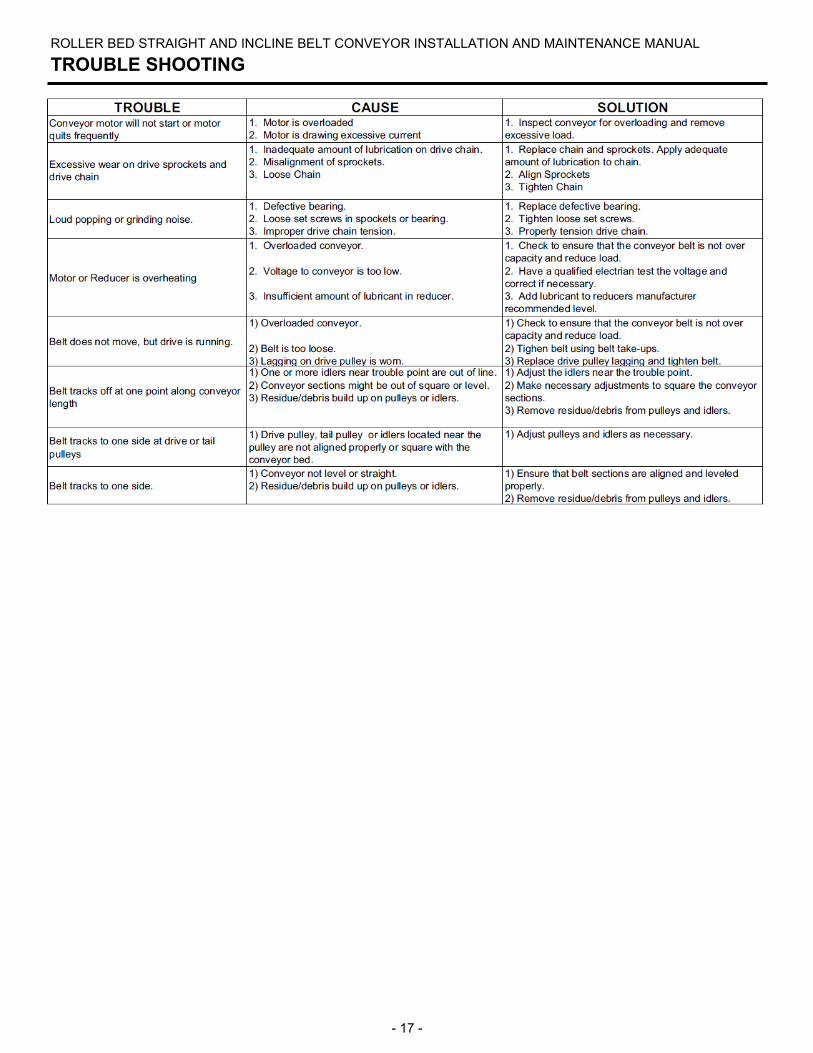
ROLLER BED STRAIGHT AND INCLINE BELT CONVEYOR INSTALLATION AND MAINTENANCE MANUAL
TROUBLE SHOOTING
- 18 -
ROLLER BED STRAIGHT AND INCLINE BELT CONVEYOR INSTALLATION AND MAINTENANCE MANUAL
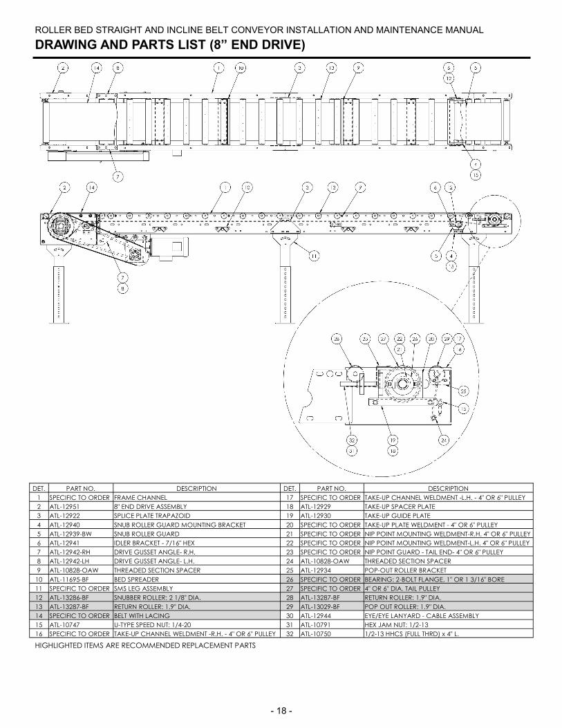
DRAWING AND PARTS LIST (8” END DRIVE)
HIGHLIGHTED ITEMS ARE RECOMMENDED REPLACEMENT PARTS
DET. PART NO. DESCRIPTION DET. PART NO. DESCRIPTION
1 SPECIFIC TO ORDER FRAME CHANNEL 17 SPECIFIC TO ORDER TAKE-UP CHANNEL WELDMENT -L.H. - 4" OR 6" PULLEY
2 ATL-12951 8" END DRIVE ASSEMBLY 18 ATL-12929 TAKE-UP SPACER PLATE
3 ATL-12922 SPLICE PLATE TRAPAZOID 19 ATL-12930 TAKE-UP GUIDE PLATE
4 ATL-12940 SNUB ROLLER GUARD MOUNTING BRACKET 20 SPECIFIC TO ORDER TAKE-UP PLATE WELDMENT - 4" OR 6" PULLEY
5 ATL-12939-BW SNUB ROLLER GUARD 21 SPECIFIC TO ORDER NIP POINT MOUNTING WELDMENT-R.H. 4" OR 6" PULLEY
6 ATL-12941 IDLER BRACKET - 7/16" HEX 22 SPECIFIC TO ORDER NIP POINT MOUNTING WELDMENT-L.H. 4" OR 6" PULLEY
7 ATL-12942-RH DRIVE GUSSET ANGLE- R.H. 23 SPECIFIC TO ORDER NIP POINT GUARD - TAIL END- 4" OR 6" PULLEY
8 ATL-12942-LH DRIVE GUSSET ANGLE- L.H. 24 ATL-10828-OAW THREADED SECTION SPACER
9 ATL-10828-OAW THREADED SECTION SPACER 25 ATL-12934 POP-OUT ROLLER BRACKET
10 ATL-11695-BF BED SPREADER 26 SPECIFIC TO ORDER BEARING: 2-BOLT FLANGE, 1" OR 1 3/16" BORE
11 SPECIFIC TO ORDER SMS LEG ASSEMBLY 27 SPECIFIC TO ORDER 4" OR 6" DIA. TAIL PULLEY
12 ATL-13286-BF SNUBBER ROLLER: 2 1/8" DIA. 28 ATL-13287-BF RETURN ROLLER: 1.9" DIA.
13 ATL-13287-BF RETURN ROLLER: 1.9" DIA. 29 ATL-13029-BF POP OUT ROLLER: 1.9" DIA.
14 SPECIFIC TO ORDER BELT WITH LACING 30 ATL-12944 EYE/EYE LANYARD - CABLE ASSEMBLY
15 ATL-10747 U-TYPE SPEED NUT: 1/4-20 31 ATL-10791 HEX JAM NUT: 1/2-13
16 SPECIFIC TO ORDER TAKE-UP CHANNEL WELDMENT -R.H. - 4" OR 6" PULLEY 32 ATL-10750 1/2-13 HHCS (FULL THRD) x 4" L.
- 19 -
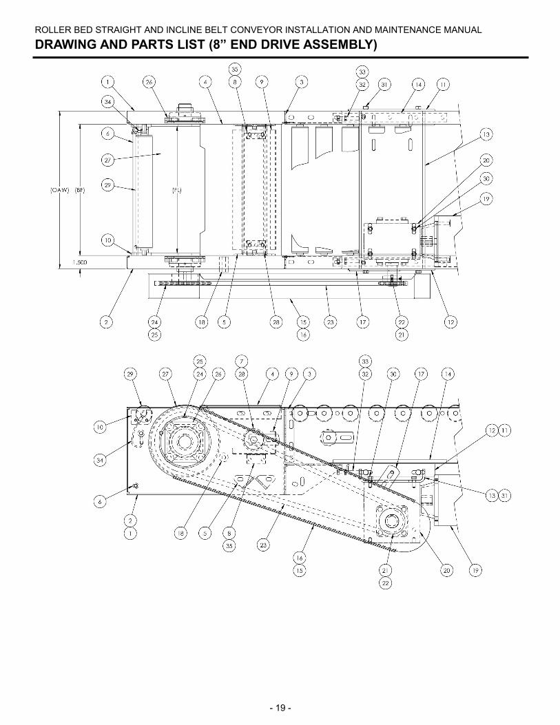
ROLLER BED STRAIGHT AND INCLINE BELT CONVEYOR INSTALLATION AND MAINTENANCE MANUAL
DRAWING AND PARTS LIST (8” END DRIVE ASSEMBLY)

- 20 -
ROLLER BED STRAIGHT AND INCLINE BELT CONVEYOR INSTALLATION AND MAINTENANCE MANUAL
DRAWING AND PARTS LIST (8” END DRIVE ASSEMBLY)
HIGHLIGHTED ITEMS ARE RECOMMENDED REPLACEMENT PARTS
DET. PART NO. DESCRIPTION DET. PART NO. DESCRIPTION
1 ATL-12949-RH DRIVE SUPPORT CHANNEL- R.H. 19 SPECIFIC TO ORDER MOTOR
2 ATL-12949-LH DRIVE SUPPORT CHANNEL- L.H. 20 SPECIFIC TO ORDER REDUCER
3 ATL-12943 BUTT COUPLING ANGLE 21 SPECIFIC TO ORDER DRIVE SPROCKET (REDUCER)
4 ATL-12945-BW SLIDER GUARD WELDMENT 22 SPECIFIC TO ORDER DRIVE SPROCKET - SHAFT KEY
5 ATL-11695-BF BED SPREADER 23 SPECIFIC TO ORDER DRIVE CHAIN WITH CONNECTING LINK
6 ATL-10828-OAW THREADED SECTION SPACER 24 ATL-11252 DRIVE SPROCKET (DRIVE PULLEY)
7 ATL-10019 SNUB ROLLER BRACKET - 11/16" HEX 25 ATL-10744 PULLEY - SHAFT KEY
8 ATL-11083 SNUB ROLLER GUARD MOUNTING BRACKET 26 ATL-10004 BEARING: 4-BOLT FLANGE, 1 7/16" BORE
9 ATL-12950-BW SNUB ROLLER GUARD - DRIVE END 27 ATL-10758-FL 8" DIA. DRIVE PULLEY WITH LAGGING
10 ATL-12934 POP-OUT ROLLER BRACKET 28 ATL-13028-BF SNUB ROLLER: 2 9/16" DIA.
11 ATL-12850-RH MOTOR BASE SUPPORT ANGLE - R.H. 29 ATL-13029-BF POP OUT ROLLER: 1.9" DIA.
12 ATL-12850-LH MOTOR BASE SUPPORT ANGLE - L.H. 30 SPECIFIC TO ORDER REDUCER BOLT
13 SPECIFIC TO ORDER MOTOR BASE WELDMENT 31 ATL-10749 HEX HEAD BOLT: 3/8-16 x 1" L. (GRADE 8)
14 ATL-10781 REDUCER BASE REINFORCEMENT BAR 32 ATL-10787 TAKE-UP BOLT: 3/8-16 x 2 1/4" L.
15 ATL-11090 CHAIN GUARD FRONT WELDMENT 33 ATL-10790 HEX JAM NUT: 3/8-16
16 ATL-11091 CHAIN GUARD BACK PLATE 34 ATL-12944 EYE/EYE LANYARD - CABLE ASSEMBLY
17 ATL-10780 CHAIN GUARD MOUNTING BAR 35 ATL-10747 U-TYPE SPEED NUT: 1/4-20
18 ATL-10824 SPACER
- 21 -
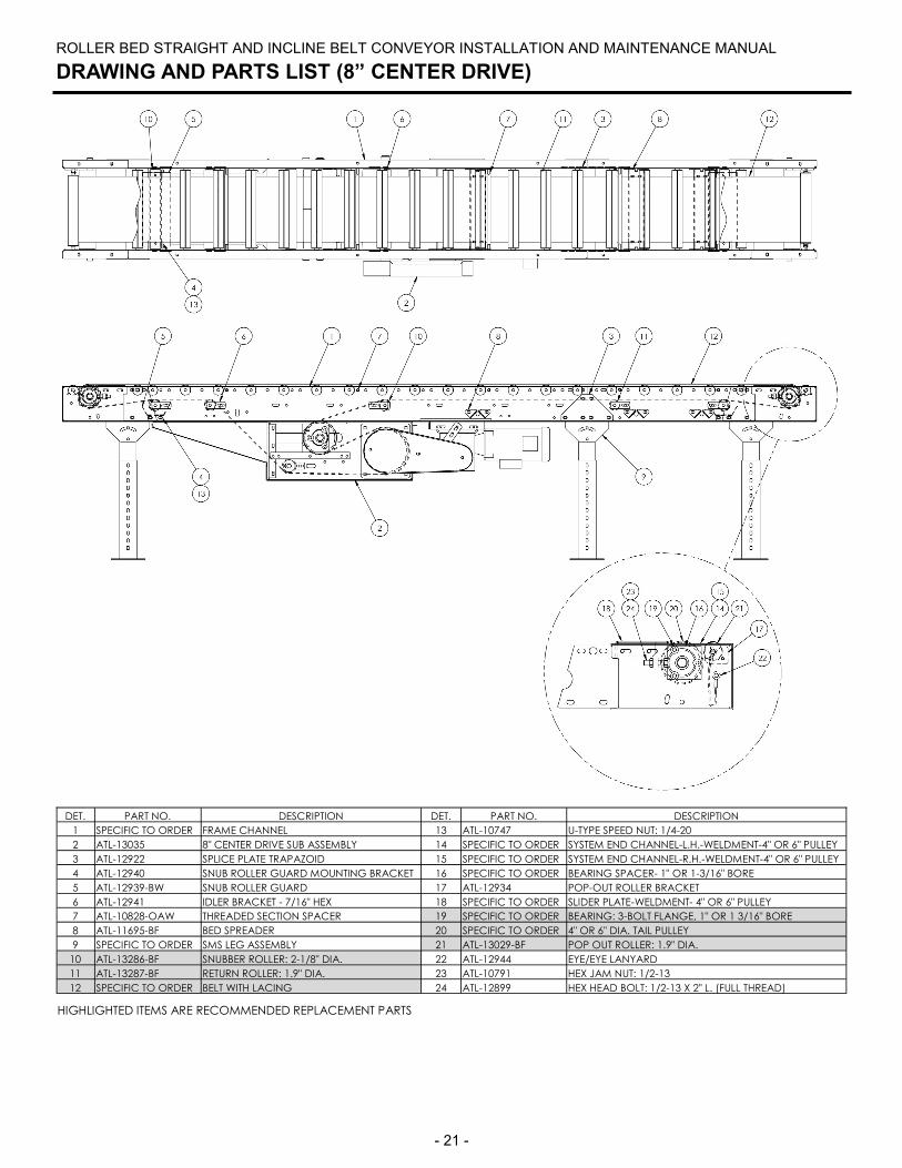
ROLLER BED STRAIGHT AND INCLINE BELT CONVEYOR INSTALLATION AND MAINTENANCE MANUAL
DRAWING AND PARTS LIST (8” CENTER DRIVE)
HIGHLIGHTED ITEMS ARE RECOMMENDED REPLACEMENT PARTS
DET. PART NO. DESCRIPTION DET. PART NO. DESCRIPTION
1 SPECIFIC TO ORDER FRAME CHANNEL 13 ATL-10747 U-TYPE SPEED NUT: 1/4-20
2 ATL-13035 8" CENTER DRIVE SUB ASSEMBLY 14 SPECIFIC TO ORDER SYSTEM END CHANNEL-L.H.-WELDMENT-4" OR 6" PULLEY
3 ATL-12922 SPLICE PLATE TRAPAZOID 15 SPECIFIC TO ORDER SYSTEM END CHANNEL-R.H.-WELDMENT-4" OR 6" PULLEY
4 ATL-12940 SNUB ROLLER GUARD MOUNTING BRACKET 16 SPECIFIC TO ORDER BEARING SPACER- 1" OR 1-3/16" BORE
5 ATL-12939-BW SNUB ROLLER GUARD 17 ATL-12934 POP-OUT ROLLER BRACKET
6 ATL-12941 IDLER BRACKET - 7/16" HEX 18 SPECIFIC TO ORDER SLIDER PLATE-WELDMENT- 4" OR 6" PULLEY
7 ATL-10828-OAW THREADED SECTION SPACER 19 SPECIFIC TO ORDER BEARING: 3-BOLT FLANGE, 1" OR 1 3/16" BORE
8 ATL-11695-BF BED SPREADER 20 SPECIFIC TO ORDER 4" OR 6" DIA. TAIL PULLEY
9 SPECIFIC TO ORDER SMS LEG ASSEMBLY 21 ATL-13029-BF POP OUT ROLLER: 1.9" DIA.
10 ATL-13286-BF SNUBBER ROLLER: 2-1/8" DIA. 22 ATL-12944 EYE/EYE LANYARD
11 ATL-13287-BF RETURN ROLLER: 1.9" DIA. 23 ATL-10791 HEX JAM NUT: 1/2-13
12 SPECIFIC TO ORDER BELT WITH LACING 24 ATL-12899 HEX HEAD BOLT: 1/2-13 X 2" L. (FULL THREAD)
- 22 -
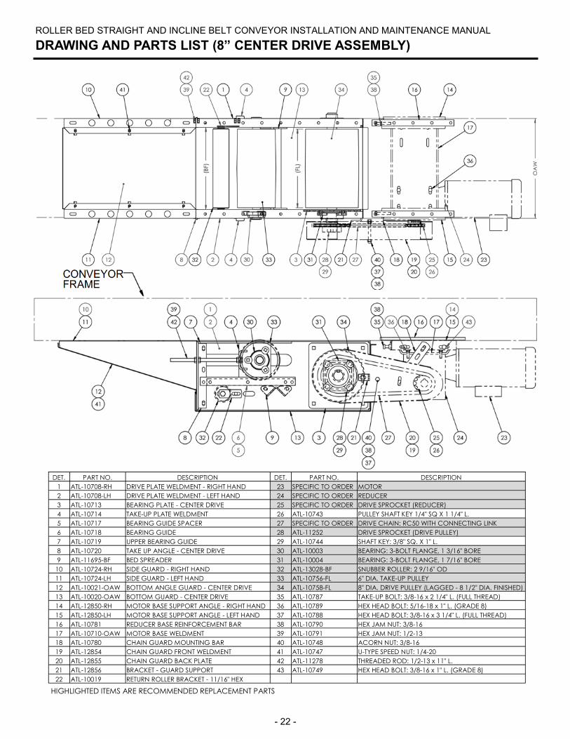
ROLLER BED STRAIGHT AND INCLINE BELT CONVEYOR INSTALLATION AND MAINTENANCE MANUAL
DRAWING AND PARTS LIST (8” CENTER DRIVE ASSEMBLY)
DET. PART NO. DESCRIPTION DET. PART NO. DESCRIPTION
1 ATL-10708-RH DRIVE PLATE WELDMENT - RIGHT HAND 23 SPECIFIC TO ORDER MOTOR
2 ATL-10708-LH DRIVE PLATE WELDMENT - LEFT HAND 24 SPECIFIC TO ORDER REDUCER
3 ATL-10713 BEARING PLATE - CENTER DRIVE 25 SPECIFIC TO ORDER DRIVE SPROCKET (REDUCER)
4 ATL-10714 TAKE-UP PLATE WELDMENT 26 ATL-10743 PULLEY SHAFT KEY 1/4" SQ X 1 1/4" L.
5 ATL-10717 BEARING GUIDE SPACER 27 SPECIFIC TO ORDER DRIVE CHAIN: RC50 WITH CONNECTING LINK
6 ATL-10718 BEARING GUIDE 28 ATL-11252 DRIVE SPROCKET (DRIVE PULLEY)
7 ATL-10719 UPPER BEARING GUIDE 29 ATL-10744 SHAFT KEY: 3/8" SQ. X 1" L.
8 ATL-10720 TAKE UP ANGLE - CENTER DRIVE 30 ATL-10003 BEARING: 3-BOLT FLANGE, 1 3/16" BORE
9 ATL-11695-BF BED SPREADER 31 ATL-10004 BEARING: 3-BOLT FLANGE, 1 7/16" BORE
10 ATL-10724-RH SIDE GUARD - RIGHT HAND 32 ATL-13028-BF SNUBBER ROLLER: 2 9/16" OD
11 ATL-10724-LH SIDE GUARD - LEFT HAND 33 ATL-10756-FL 6" DIA. TAKE-UP PULLEY
12 ATL-10021-OAW BOTTOM ANGLE GUARD - CENTER DRIVE 34 ATL-10758-FL 8" DIA. DRIVE PULLEY (LAGGED - 8 1/2" DIA. FINISHED)
13 ATL-10020-OAW BOTTOM GUARD - CENTER DRIVE 35 ATL-10787 TAKE-UP BOLT: 3/8-16 x 2 1/4" L. (FULL THREAD)
14 ATL-12850-RH MOTOR BASE SUPPORT ANGLE - RIGHT HAND 36 ATL-10789 HEX HEAD BOLT: 5/16-18 x 1" L. (GRADE 8)
15 ATL-12850-LH MOTOR BASE SUPPORT ANGLE - LEFT HAND 37 ATL-10788 HEX HEAD BOLT: 3/8-16 x 3 1/4" L. (FULL THREAD)
16 ATL-10781 REDUCER BASE REINFORCEMENT BAR 38 ATL-10790 HEX JAM NUT: 3/8-16
17 ATL-10710-OAW MOTOR BASE WELDMENT 39 ATL-10791 HEX JAM NUT: 1/2-13
18 ATL-10780 CHAIN GUARD MOUNTING BAR 40 ATL-10748 ACORN NUT: 3/8-16
19 ATL-12854 CHAIN GUARD FRONT WELDMENT 41 ATL-10747 U-TYPE SPEED NUT: 1/4-20
20 ATL-12855 CHAIN GUARD BACK PLATE 42 ATL-11278 THREADED ROD: 1/2-13 x 11" L.
21 ATL-12856 BRACKET - GUARD SUPPORT 43 ATL-10749 HEX HEAD BOLT: 3/8-16 x 1" L. (GRADE 8)
22 ATL-10019 RETURN ROLLER BRACKET - 11/16" HEX
HIGHLIGHTED ITEMS ARE RECOMMENDED REPLACEMENT PARTS
- 23 -
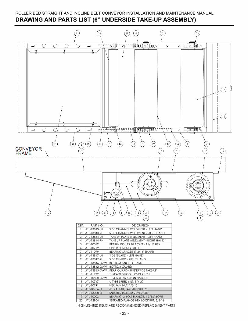
ROLLER BED STRAIGHT AND INCLINE BELT CONVEYOR INSTALLATION AND MAINTENANCE MANUAL
DRAWING AND PARTS LIST (6” UNDERSIDE TAKE-UP ASSEMBLY)
HIGHLIGHTED ITEMS ARE RECOMMENDED REPLACEMENT PARTS
DET. PART NO. DESCRIPTION
1 ATL-13843-LH SIDE CHANNEL WELDMENT - LEFT HAND
2 ATL-13843-RH SIDE CHANNEL WELDMENT - RIGHT HAND
3 ATL-13844-LH TAKE-UP PLATE WELDMENT - LEFT HAND
4 ATL-13844-RH TAKE UP PLATE WELDMENT - RIGHT HAND
5 ATL-10019 RETURN ROLLER BRACKET - 11/16" HEX
6 ATL-10719 UPPER BEARING GUIDE
7 ATL-11099 BEARING SPACER (1 3/16" SHAFT)
8 ATL-13847-LH SIDE GUARD - LEFT HAND
9 ATL-13847-RH SIDE GUARD - RIGHT HAND
10 ATL-13846-OAW BOTTOM ANGLE GUARD
11 ATL-13842-OAW BOTTOM GUARD
12 ATL-13845-OAW REAR GUARD - UNDERSIDE TAKE-UP
13 ATL-11279 THREADED ROD: 1/2-13 X 10" L.
14 ATL-10828-OAW THREADED SECTION SPACER
15 ATL-10747 U-TYPE SPEED NUT: 1/4-20
16 ATL-10791 HEX JAM NUT: 1/2-13
17 ATL-10756-FL 6" DIA. TAIL/TAKE-UP PULLEY
18 ATL-13028-BF SNUBBER ROLLER: 2 9/16" OD
19 ATL-10003 BEARING: 3-BOLT FLANGE, 1 3/16" BORE
20 ATL-12904 SERRATED FLANGE HEX LOCKNUT: 3/8-16
- 24 -
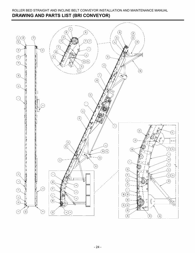
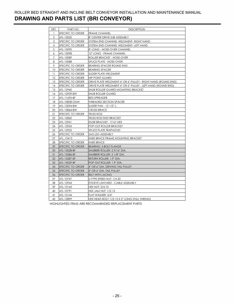
ROLLER BED STRAIGHT AND INCLINE BELT CONVEYOR INSTALLATION AND MAINTENANCE MANUAL
DRAWING AND PARTS LIST (BRI CONVEYOR)
- 25 -
DET. PART NO. DESCRIPTION
1 SPECIFIC TO ORDER FRAME CHANNEL
2 ATL-13035 8" CENTER DRIVE SUB ASSEMBLY
3 SPECIFIC TO ORDER SYSTEM END CHANNEL WELDMENT- RIGHT HAND
4 SPECIFIC TO ORDER SYSTEM END CHANNEL WELDMENT- LEFT HAND
5 ATL-13090 8" LONG - NOSE-OVER CHANNEL
6 ATL-13098 12" LONG - FRAME CHANNEL
7 ATL-13089 ROLLER BRACKET - NOSE-OVER
8 ATL-13088 SPLICE PLATE - NOSE-OVER
9 SPECIFIC TO ORDER BEARING SPACER ROUND END
10 SPECIFIC TO ORDER BEARING SPACER
11 SPECIFIC TO ORDER SLIDER PLATE WELDMENT
12 SPECIFIC TO ORDER NIP POINT GUARD
13 SPECIFIC TO ORDER DRIVE PLATE WELDMENT 4" OR 6" PULLEY - RIGHT HAND (ROUND END)
14 SPECIFIC TO ORDER DRIVE PLATE WELDMENT 4" OR 6" PULLEY - LEFT HAND (ROUND END)
15 ATL-12940 SNUB ROLLER GUARD MOUNTING BRACKET
16 ATL-12939-BW SNUB ROLLER GUARD
17 ATL-11695-BF BED SPREADER
18 ATL-10828-OAW THREADED SECTION SPACER
19 ATL-13094-BW SLIDER PAN - 10 1/2" L.
20 ATL-12864-BW CROSS BRACE
21 SPECIFIC TO ORDER TRUSS ROD
22 ATL-12860 TRUSS ROD END BRACKET
23 ATL-12941 IDLER BRACKET - 7/16" HEX
24 ATL-12934 POP-OUT ROLLER BRACKET
25 ATL-12922 SPLICE PLATE TRAPAZOID
26 SPECIFIC TO ORDER SMS LEG ASSEMBLY
27 ATL_10413 KNEE BRACE FRAME MOUNTING BRACKET
28 SPECIFIC TO ORDER KNEE BRACE
29 SPECIFIC TO ORDER BEARING: 3-BOLT FLANGE
30 ATL-13028-BF SNUBBER ROLLER: 2 9/16" DIA.
31 ATL-13286-BF SNUBBER ROLLER: 2 1/8" DIA.
32 ATL-13287-BF RETURN ROLLER: 1.9" DIA.
33 ATL-13029-BF POP OUT ROLLER: 1.9" DIA.
34 SPECIFIC TO ORDER 4" OR 6" DIA. DRIVING TAIL PULLEY
35 SPECIFIC TO ORDER 4" OR 6" DIA. TAIL PULLEY
36 SPECIFIC TO ORDER BELT WITH LACING
37 ATL-10747 U-TYPE SPEED NUT: 1/4-20
38 ATL-12944 EYE/EYE LANYARD - CABLE ASSEMBLY
39 ATL-13143 HEX NUT: 3/4-10
40 ATL-10791 HEX JAM NUT: 1/2-13
41 ATL-13144 FLAT WASHER: 3/4"
42 ATL-12899 HEX HEAD BOLT: 1/2-13 X 2" LONG (FULL THREAD)
ROLLER BED STRAIGHT AND INCLINE BELT CONVEYOR INSTALLATION AND MAINTENANCE MANUAL
DRAWING AND PARTS LIST (BRI CONVEYOR)
HIGHLIGHTED ITEMS ARE RECOMMENDED REPLACEMENT PARTS
- 26 -
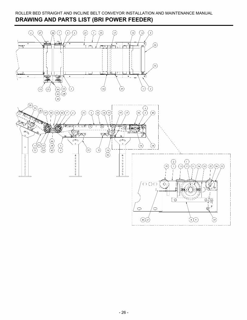
ROLLER BED STRAIGHT AND INCLINE BELT CONVEYOR INSTALLATION AND MAINTENANCE MANUAL
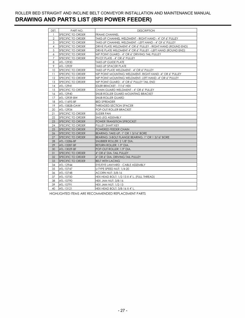
DRAWING AND PARTS LIST (BRI POWER FEEDER)
- 27 -
ROLLER BED STRAIGHT AND INCLINE BELT CONVEYOR INSTALLATION AND MAINTENANCE MANUAL
DRAWING AND PARTS LIST (BRI POWER FEEDER)
DET. PART NO. DESCRIPTION
1 SPECIFIC TO ORDER FRAME CHANNEL
2 SPECIFIC TO ORDER TAKE-UP CHANNEL WELDMENT - RIGHT HAND - 4" OF 6" PULLEY
3 SPECIFIC TO ORDER TAKE-UP CHANNEL WELDMENT - LEFT HAND - 4" OF 6" PULLEY
4 SPECIFIC TO ORDER DRIVE PLATE WELDMENT 4" OR 6" PULLEY - RIGHT HAND (ROUND END)
5 SPECIFIC TO ORDER DRIVE PLATE WELDMENT 4" OR 6" PULLEY - LEFT HAND (ROUND END)
6 SPECIFIC TO ORDER NIP POINT GUARD - 4" OR 6" DRIVING TAIL PULLEY
7 SPECIFIC TO ORDER PIVOT PLATE - 4" OR 6" PULLEY
8 ATL-12930 TAKE-UP GUIDE PLATE
9 ATL-12929 TAKE-UP SPACER PLATE
10 SPECIFIC TO ORDER TAKE-UP PLATE WELDMENT - 4" OR 6" PULLEY
11 SPECIFIC TO ORDER NIP POINT MOUNTING WELDMENT- RIGHT HAND -4" OR 6" PULLEY
12 SPECIFIC TO ORDER NIP POINT MOUNTING WELDMENT- LEFT HAND -4" OR 6" PULLEY
13 SPECIFIC TO ORDER NIP POINT GUARD - 4" OR 6" PULLEY TAIL END
14 ATL-12941 IDLER BRACKET - 7/16" HEX
15 SPECIFIC TO ORDER CHAIN GUARD WELDMENT - 4" OR 6" PULLEY
16 ATL-12940 SNUB ROLLER GUARD MOUNTING BRACKET
17 ATL-12939-BW SNUB ROLLER GUARD
18 ATL-11695-BF BED SPREADER
19 ATL-10828-OAW THREADED SECTION SPACER
20 ATL-12934 POP-OUT ROLLER BRACKET
21 SPECIFIC TO ORDER SLIDER PAN
22 SPECIFIC TO ORDER SMS LEG ASSEMBLY
23 SPECIFIC TO ORDER POWER TRANSITION SPROCKET
24 SPECIFIC TO ORDER PULLEY SHAFT KEY
25 SPECIFIC TO ORDER POWERED FEEDER CHAIN
26 SPECIFIC TO ORDER BEARING: TAKE-UP, 1" OR 1 3/16" BORE
27 SPECIFIC TO ORDER BEARING: 3-BOLT FLANGE BEARING, 1" OR 1 3/16" BORE
28 ATL-13286-BF SNUBBER ROLLER: 2 1/8" DIA.
29 ATL-13287-BF RETURN ROLLER: 1.9" DIA.
30 ATL-13029-BF POP-OUT ROLLER: 1.9" DIA.
31 SPECIFIC TO ORDER 4" OR 6" DIA. TAIL PULLEY
32 SPECIFIC TO ORDER 4" OR 6" DIA. DRIVING TAIL PULLEY
33 SPECIFIC TO ORDER BELT WITH LACING
34 ATL-12944 EYE/EYE LANYARD - CABLE ASSEMBLY
35 ATL-10747 U-TYPE SPEED NUT: 1/4-20
36 ATL-10748 ACORN NUT: 3/8-16
37 ATL-10750 HEX HEAD BOLT: 1/2-13 X 4" L. (FULL THREAD)
38 ATL-10790 HEX JAM NUT: 3/8-16
39 ATL-10791 HEX JAM NUT: 1/2-13
40 ATL-13121 HEX HEAD BOLT: 3/8-16 X 4" L.
HIGHLIGHTED ITEMS ARE RECOMMENDED REPLACEMENT PARTS
- 28 -
ROLLER BED STRAIGHT AND INCLINE BELT CONVEYOR INSTALLATION AND MAINTENANCE MANUAL
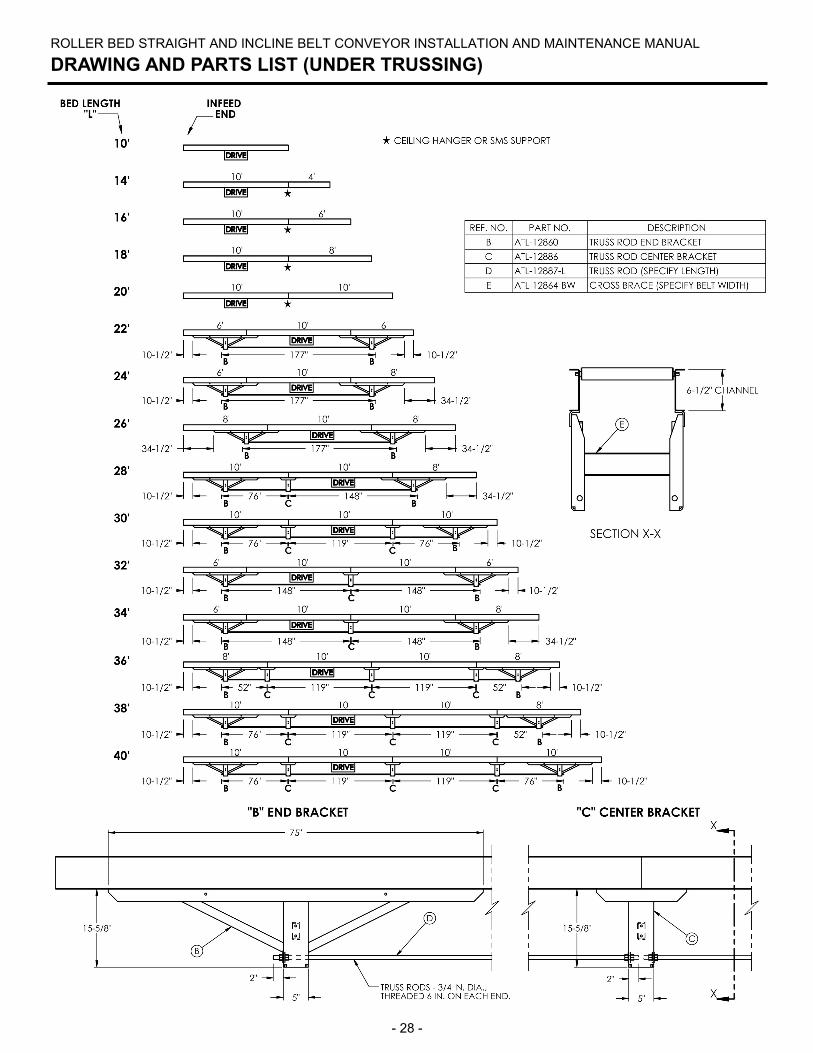
DRAWING AND PARTS LIST (UNDER TRUSSING)


![1 SERIES Belt Conveyor System B090 - Bett Sistemi Srl€¦ · CONVEYOR BELT DEVELOPMENT CALCULATION FORMULA Conveyor belt length = 300 + {[(L-94)-(2• Conveyor belt thick. )]•2}](https://img.pdfslide.us/doc/110x75/5ad3c4047f8b9a48398b7ae4/1-series-belt-conveyor-system-b090-bett-sistemi-conveyor-belt-development-calculation.jpg)