Embed Size (px)
Citation preview

1 (40)
Edition 01-2007
Installation and MaintenanceInstruction Manual
LAKC RANGE
2 (40)
Edition 01-2007
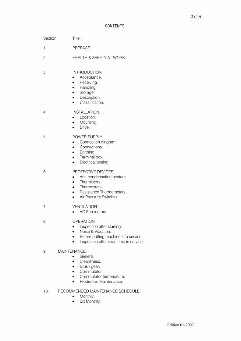
CONTENTS
Section Title:
1. PREFACE.
2. HEALTH & SAFETY AT WORK.
3. INTRODUCTION.• Acceptance.• Receiving. • Handling. • Storage.• Description.• Classification.
4. INSTALLATION.• Location. • Mounting. • Drive.
5. POWER SUPPLY.• Connection diagram. • Connections. • Earthing. • Terminal box. • Electrical testing.
6. PROTECTIVE DEVICES.• Anti-condensation heaters. • Thermistors. • Thermostats. • Resistance Thermometers. • Air Pressure Switches.
7. VENTILATION.• AC Fan motors.
8. OPERATION.• Inspection after starting. • Noise & Vibration. • Before putting machine into service. • Inspection after short time in service.
9. MAINTENANCE.• General. • Cleanliness. • Brush gear. • Commutator. • Commutator temperature.• Productive Maintenance.
10. RECOMMENDED MAINTENANCE SCHEDULE.• Monthly.• Six Monthly.

3 (40)
Edition 01-2007
CONTENTS
Section Title:
11. MECHANICAL.• Bolts.• Shaft.• Ventilation.• Vibration.
12. LUBRICATION.
13. REPAIR.
14. FAILURE.
15. DISMANTLING.• Armature removal.• Armature installation.• Bearing removal.• Bearing replacement.
16. AIR-WATER COOLERS.• General.• Installation.• Lifting.• Operation.• Maintenance.• Ancillary equipment.
17. AIR-AIR COOLERS.• General.• Installation.• Lifting.• Operation.• Maintenance.• Ancillary equipment.
18. FILTERS.• Cleaning.
19. MOTOR PROBLEMS – QUICK CHECKLIST.• Mechanical.• Electrical.• Commutation.
20. REPORT FORMS.• Pre-commissioning.• Commissioning.• Maintenance.

4 (40)
Edition 01-2007
1. PREFACE
The purpose of this manual is to describe the Installation, Operation and Maintenance of the LAKCd.c. machines.
The design of LAKC d.c. machines is subject to constant review and the information given mayvary from that manufactured due to improvements in design techniques.
The manual has been sectionalised and only the sections applicable to your particular machineshould be considered. Before any commissioning or checking of the machines is carried out, thecomplete book should be studied so that a complete understanding of the operation of themachines is obtained.
THE INSTRUCTIONS IN THIS MANUAL ARE GIVEN FOR INFORMATION AND GUIDANCE. THE COMPANY CANNOTACCEPT ANY RESPONSIBILITY EITHER FOR THE MANNER IN, WHICH THEY ARE OBSERVED, OR FOR ANYCONSEQUENCES THEREOF. All enquiries for spare parts should be directed to Thrige Electric.
Technical queries or requests for further information should be directed to Thrige Electric.
In any correspondence or enquiry, please quote the serial number and frame size as detailed onthe machine rating plate.

5 (40)
Edition 01-2007
2. HEALTH & SAFETY AT WORK
THE INSTRUCTIONS IN THIS MANUAL ARE GIVEN FOR INFORMATION AND GUIDANCE. THE COMPANY CANNOTACCEPT ANY RESPONSIBILITY EITHER FOR THE MANNER IN, WHICH THEY ARE OBSERVED, OR FOR ANYCONSEQUENCES THEREOF.
THE IMPROPER USE OF ELECTRICAL EQUIPMENT IS HAZARDOUS TO HEALTH !THEREFORE EVERY PRECAUTION SHOULD BE TAKEN TO MINIMISE THE HAZARD.THE FOLLOWING GUIDANCE NOTES, WHEN ACTED UPON, SHOULD CONSIDERABLYMINIMISE HAZARDOUS INCIDENTS.
INSTALLATION:
Where engineers make installation, suitably qualified personnel in accordance with relevant legislation,regulations and accepted rules of the art should erect the equipment. In particular, the recommendationscontained in the regulations with regard to the earthing of electrical equipment must be rigorously adhered to.
OPERATION & MAINTENANCE:
Engineers responsible for operation and maintenance of the equipment supplied under this contract, shouldfamiliarise themselves with the information contained in this manual, and with the recommendations given bymanufacturers of the associated equipment and also with the relevant regulations currently in force.
WARNING!
• It is essential that all covers are in place and that all guards and/or safety fences to protect any exposedrotating parts, surfaces and/or pits, are fitted before the machine is started.
• All adjustments to the machine must be carried out whilst the machine is stationery and isolated from allelectrical supplies. Replace all covers and/or safety fences before re-starting the machine.
• When maintenance is being carried out, suitable WARNING signs should be prominently displayed and thenecessary precautions taken to ensure power is not inadvertently switched on to the equipment whilst work isin progress, or is not yet complete.
• When power is restored to the equipment, personnel should not be allowed to work on auxiliary circuits, e.g.heaters, temperature detectors, current transformers, etc.
• Lifting procedures - Ensure that the recommendations given in this manual are adhered to at all times.

6 (40)
Edition 01-2007
3. INTRODUCTION:
This Installation & Maintenance Manual covers the LAKC range of compensated d.c. machines.
WARNING! INSTALLATION OF THE MACHINE WHERE HAZARDOUS, INFLAMMABLE OR COMBUSTIBLEVAPOURS OR DUST PRESENT A POSSIBILITY OF EXPLOSION OR FIRE, SHOULD BE INACCORDANCE WITH THE CURRENT NATIONAL STANDARDS AND CONSISTENT WITHSOUND LOCAL PRACTICES.
These instructions do not purport to cover all details or variation in equipment, or to provide forevery possible contingency or hazard to be met in connection with installation, operation andmaintenance of the machines. Should further information be desired, or should particularproblems arise which are not sufficiently covered for the purchasers purposes, the matter shouldbe referred back to Thrige Electric.
ACCEPTANCE:
Thoroughly inspect the equipment before accepting delivery from the carrier. If any of theequipment details in the Advice Note arrive damaged, or the quantity short, ensure that the carrieris notified and information sent to Thrige Electric in writing immediately.
RECEIVING:
The equipment should be placed under adequate cover immediately upon receipt, as packingcovers are NOT suitable for out-of-doors or unprotected storage. This includes adequateprotection from construction dirt, during and after installation.
HANDLING:
Four lugs are provided for lifting. Ensure that all lugs are used, and that a suitable sling isemployed so that the angle is not so great as to impose excess strain on the lugs. The lugs areintended for lifting only the machine with standard accessories such as tachogenerators, blowerunits, etc. Do not lift the machine by the shaft extension(s). The machine weight is stamped on therating plate.
WARNING! Before attempting to lift any machine, check the outline drawing for the liftingpoints and their limitations. Unless otherwise specified on the outline drawing,lifting points are intended to support only the part to which they are attached.The devices are not suitable, in general, for lifting the total weight of theassembled machine. They are not to be used to lift the machine plus additionalequipment such as driven equipment or heat exchangers, etc. Failure to observethese precautions may result in damage to equipment, injury to personnel, or both.
The handling of individual armatures or machine parts is described in the Maintenance Section.

7 (40)
Edition 01-2007
STORAGE:
If a machine, or any part of a machine, is not to be installed immediately, it should be stored in aclean, dry atmosphere, free from extreme variations in temperature. Outdoor storage or fluctuatingtemperatures may cause condensation, which must be avoided.
If the temperature of the storage room varies to such an extent that the windings and coils areexposed to moisture condensation, the machine should be protected by a safe, reliable heatingsystem such as anti-condensation heaters, which will keep the internal temperature of the machineslightly above that of the storage room.
Brushes should not be allowed to remain in contact with the commutator surface during prolongedstorage; otherwise corrosion may occur and later result in flat spots on the commutator, withcorresponding poor and destructive commutation.
The presence of moisture on the internal machine parts can cause electrical failure of insulatedwindings and/or mechanical failure of highly stressed armature glass banding.
If the machine has been exposed to low temperatures for an extended period of time, unpacking itbefore it has reached room temperature will cause it to sweat. If any internal condensation occurs,then the machine(s) must be thoroughly dried out and the insulation resistance checked prior tobeing put into service.
If the machine(s) is to be in storage for any length of time, it should be arranged that the shaft berotated to a different position every two months, to prevent bearing damage due to brinnelling orfretting corrosion.
If for any reason the machine(s) is to be stored for more than one year, bearings should be flushedof old lubricant and re-lubricated prior to being put into service.
All exposed machine parts are coated with a rust inhibitor prior to shipment. These surfacesshould be examined carefully for signs of rust and moisture, and re-coated if necessary. Oncestarted, rust will continue if the surface is re-coated without first removing all rust and moisture.Rust may be removed by careful use of fine abrasive paper. The rust inhibitor can be removed byuse of solvent such as mineral spirits.
WARNING! Mineral spirits are flammable and moderately toxic. The usual precautions forhandling chemicals of this type should be adhered to, these include:
• Avoid excessive contact with the skin.• Use only in well ventilated areas.• Take the necessary precautions to prevent fire or explosion hazards.
DESCRIPTION:
The LAKC range of compensated dc machines has a family resemblance, even though it covers awide range of sizes. All standard machines are equipped with a shaft extension and key at thedrive-end and a mounting arrangement suitable for mounting all standard tachogenerators,encoders or speed limiting devices at the non-drive/commutator end.
CLASSIFICATION:
The LAKC range of compensated dc motors is a robust standard dc machine designed for generalindustrial service. IEC 34 define these motors.

8 (40)
Edition 01-2007
4. INSTALLATION:
WARNING! DC machines have characteristics, which can cause serious or fatal injury unlessthey are selected, installed, maintained and operated by qualified personnel familiarwith the special requirements of DC machines.
Disconnect power before touching any internal part. High voltage may be presenteven when the machine is not rotating. If used with a rectifier excitation supply,disconnect all ac line connections to the excitation source. Disconnect all dc fieldconnections. Failure to observe these precautions may result in injury topersonnel.
Installation should be in accordance with the National Electrical Regulations andconsistent with all local codes of practice. All exposed rotating parts such ascouplings; belts and chains should be guarded as necessary to prevent accidentalcontact with moving parts. Machines accessible to the public should be furtherguarded by screening, guard rails, etc., to prevent the public from coming intocontact with the equipment. Failure to observe these precautions may result ininjury to personnel.
LOCATION:
Locate the machine(s) where clean air has free access to the ventilation intake and outletopenings. The ambient temperature of the air entering the machine should be warmer than 10ºCbut not greater than 40ºC unless the motor has been specifically designed for a highertemperature. To avoid the collection of condensation in the machine, the dew point of the airshould be lower than the minimum surface temperature of any upstream air cooler.
In no circumstances should the machine be enclosed by a covering or placed in a position wherethe cooling air cannot circulate away from the machine or is re-circulated through the machinebefore it has a chance to re-cool back to ambient temperatures. Contaminated cooling air must be avoided. Contaminants such as moisture, dust, and liquidsand oil are easily recognised and can be eliminated. Gaseous contamination such as siliconevapour is difficult to detect but must be guarded against.
NOTE: Silicone vapour may be present and originate from sealing compounds, electricalcable sheaths and room transformers. These sources must be eliminated orguarded against.
Ready access for inspection and maintenance purposes should also be considered when sitingthe machines.
They should be installed where they will not be exposed to moisture, escaping steam, drippingpipes, paint over spray, acid, alkali, oil, gas, dust, dirt, lint, silicone vapours, or other injurioussubstances.
MOUNTING:
Machines must be mounted level on rigid foundations, and shims used where necessary toachieve this to avoid distortion of the machine frame. During installation, all ventilation and cableentries should be wrapped or otherwise protected against the ingress of dirt, moisture or otherforeign matter.
If machines are to be mounted on slide rails against a vertical surface, then steel slide rails mustbe used.

9 (40)
Edition 01-2007
DRIVE:
Standard machines are fitted with ball bearings without allowance for endplay. Proper alignmentis therefore essential otherwise severe strain may be imposed on the shaft and bearings.
For direct-coupled drives, flexible couplings are preferable and essential if there is no endplay inthe driven shaft. Ease of rotation is not conclusive proof of true alignment, which should bechecked by measuring the distance between the coupling faces at several points. Also theperipheries of the half coupling must line up.
For belt drives, the driving and driven tension must be adjusted as required for proper operation.The driving pulley should be placed as close as possible to the motor bracket.
WARNING! All shafts, coupling, belts, chains, etc. must be guarded to prevent injury topersonnel.

10 (40)
Edition 01-2007
5. POWER SUPPLY:
Check machine rating plate to ensure the voltage and type of power rating is compatible with thepower source.
CONNECTION DIAGRAM:
LAKC machines are normally with a connection drawing fixed within the terminal box lid and afurther copy inside this Installation and Maintenance manual.
CONNECTIONS:
Before connecting, insulation resistance should be checked between all windings and earth toensure that the machine has not suffered in transit, storage or installation.
All terminal connections should be checked against the machine’s connection drawing toascertain that the polarities or direction of rotation will be correct. Ensure that all boltedconnections are tight and that adequate clearances exist between conductors of opposite polarityand between conductors and earth.
EARTHING:
Earthing points are supplied on each side of the motor carcass and labelled with an earthingsymbol. Ensure that all machines are earthed correctly by scrapping back the paint to bare metalsurrounding the earthing point. Please note that any earthing stud is not designed to take any faultcurrents, only to clamp the earthing cable lugs.
WARNING! Machines must be properly earthed to avoid injury to personnel. Earthing should bein accordance with the current National Standards and consistent with sound localpractices.
TERMINAL BOX:
The terminal box is mounted on the right hand side of the machine when viewed from the drive-end as standard. The machine leads are suitable for turning the terminal box through 900 steps.
A blank un-drilled gland plate is supplied with the terminal box to facilitate the customer’s specificgland requirements.
An auxiliary terminal box is supplied when specified at time of ordering and is mounted on the sideof the main terminal box.
ELECTRICAL TESTING:
As indicated above, electrical tests must be completed on the motor prior to installation; theseshould include measurement of winding resistances and measurement of insulation resistance toearth.
WARNING! Following the insulation resistance measurement, which is usually completed using500V or higher, ensure that all windings are earthed momentarily to avoid the riskof electric shock.

11 (40)
Edition 01-2007
6. PROTECTIVE DEVICES:
Ensure that all protective devices, e.g. thermistors, thermostats, over speed switches, bearingtemperature sensors, etc., are connected and will function properly. Ensure that all couplingguards, shaft protectors, earth connectors, covers and other safety devices are properly attached.
ANTI-CONDENSATION HEATERS:
Anti-condensation heaters are furnished in the machine when ordered. These should beenergised with the correct ac voltage as shown on the rating plate.
THERMISTORS / THERMOSTATS:
Thermostats and thermistors are protective devices. They are not intended to limit machineloading or provide normal insulation life. When supplied they are mounted in the stator coils. Oneset consists of three devices; one fitted in the excitation winding, one in the compensation windingand one in the interpole winding. These devices are wired back to the main terminal box, orauxiliary terminal box (if fitted) and are coded at the terminal bar.
Since the armature rotates there is no thermal trip device fitted in the armature.
Factors such as shaft speed, ventilation, current ripple and short time overloads affect thetemperature relationship between the armature and the interpoles, therefore complete protectionfrom all conditions resulting from over-temperature is not possible. Thermistors or thermostatsare especially useful in guarding against loss of normal ventilation air; high ambient temperaturesand prolonged operation of self ventilated motors at very low speeds.
Thermostats may be used in alarm or relay circuits within the designated ratings.
Thermistors must be used with a thermistor control circuit within the designated ratings.
WARNING! Thermistors and thermostats automatically reset after the motor has cooledsomewhat. In order to prevent injury to personnel or damage to property, thecontrol circuit should be designed to prevent the automatic starting of the machinewhen the device resets.

12 (40)
THERMOCOUPLES & RESISTANCE THERMOMETERS (Pt 100):
Temperature monitoring devices such as thermocouples and platinum resistance thermometers(Pt 100) are furnished in the machine when ordered. These are fitted in the same windings as thethermistors/thermostats; i.e. one fitted in the excitation winding, one in the compensation windingand one in the interpole winding. These devices are wired back to the main terminal box, orauxiliary terminal box (if fitted). The Pt 100 devices normally fitted are of the 3-wire configurationand are colour coded.
Thermocouples and Pt 100 devices are furnished in the bearing housings when ordered. Thesedevices are wired back to the main terminal box, or auxiliary terminal box (if fitted).
3-WIRE Pt 100 – WHEATSTONE BRIDGE:
AIR PRESSURE SWITCHES:
Air pressure switches are furnithe factory at test. If they are only likely on machines supplie
Air pressure switches are genethe existence of an air sourceoperate when the filters are 1/3
90% of nominal airflow.
RL3
RL1RPt 100
PPLY
RED
RED
WHITE
Edition 01-2007
shed in the machine when ordered. These are generally pre-set atnot set, there will be a label indicating the setting procedure. This isd for use with a separate source ventilation system.
rally located on the high-pressure side of the fan and only indicate. On machines fitted with air intake/circuit filters, they are set to blocked. On machines without filters, they are set to operate at
RL2
M SU

13 (40)
Edition 01-2007
7. VENTILATION:
Ensure that all blowers, heat exchangers or central cooling systems are ready to supply thecooling air. All filters should be in place. Blowers should be checked for the correct direction ofrotation. The blower ac motors are high inertia items and repeated starting in a short period oftime should be avoided. Star/delta starting is preferred in motor powers above 4.0kW.
WARNING! Incorrect direction of rotation of cooling fans will result in reduced airflow ratesand the consequential overheating of the machine.
WARNING! It should be noted that there are two independent electrical circuits within the dcmachine, the load circuit (armature) and the excitation circuit (field). In fixed fieldmachines, i.e. without field regulation, the excitation field still requires adequateairflow, even though the load/armature circuit may only be lightly loaded.
Ensure that all air intakes are sited away from contamination or hot air sources. Ensure there issufficient room around the machine so as to avoid the possibility of re-circulating the cooling air.This along with local hot air sources will effectively increase the ambient air into the machine andcould result in overheating.
CLOSED AIR CIRCUIT COOLERS:
Refer to the specific chapters on Air-Water and Air-Air Heat Exchangers before putting the machineinto service.
AC FAN MOTORS:
Check all rating plate data, especially voltage and winding connection (star or delta).
Measure insulation resistance before commissioning and when winding dampness is suspected.
WARNING! Windings should be discharged immediately after measurement to avoid risk ofelectric shock.
DIRECT-ON-LINE OR STAR/DELTA STARTING:
A diagram of connections for the motor will be found either inside the terminal box or on the motorrating plate.
The terminal box normally contains six (6) winding terminations and at least one earth terminal.
Earthing shall be carried out in accordance with sound local practices and regulations, before themachine is connected to the supply voltage.
The voltage and connection are stamped on the nameplate.
• DIRECT-ON-LINE (DOL):
Y or ∆ winding connections may be used.

14 (40)
Edition 01-2007
• STAR/DELTA STARTING (Y/∆):
This method of starting is preferred for motor powers above 4.0kW. The supply voltage mustbe equal to the rated voltage of the machine in ∆-connection. Remove all connection linksfrom the terminal block.
TERMINALS & DIRECTION OF ROTATION:
Direction of rotation is clockwise when viewing from the shaft end, when the line phase sequenceL1, L2, L3 is connected to the terminals as shown in the diagram below.
To alter the direction of rotation, interchange the connection of any two-line cables.
CONNECTION DIAGRAM:
DELTA (∆) CONNECTION:
STAR (Y) CONNECTION:
U1
U2
V1
V2W2
W1
L2L1 L3 PE
L2L1 L3 PE
U1
U2
V1
V2W2
W1
L3
L1
L2
U1
U2
V1V2
W2
W1
L3
U2
U1W2
W1
V1V2
L1
L2

15 (40)
Edition 01-2007
8. OPERATION:
Before attempting to start the machine, ensure that:
• You have read through the Installation & Maintenance Manual and are familiar with all aspectsof running the motor and with the auxiliary equipment included for the monitoring andprotection of the machine and cooling systems.
• The carbon brushes are seated correctly on the commutator, move freely in the brush holdersand that the brush springs are firmly in position. Broken brushes must be replaced.
• The machine shaft rotates freely when turned by hand.
• The interior of the machine is dry and clean and free from any tools, metal chips or otherforeign material that may have accumulated during transit, storage or installation.
• All connections are checked for tightness.
• All covers and shaft guards are in position and that any temporary covers fitted over ventilationopenings during transit, storage or installation, are removed.
• Grease relief cover plates should be loosened or removed for a short time during initial runningto allow excess grease to be ejected.
• All terminal box covers are in place.
• The ventilation fan is running in the correct direction of rotation, and is not sucking incontamination.
• All filters are in place and that any in-transit protection is removed and not blocking the airflow.
• All protection devices such as thermal trips, airflow switches, etc., are connected into circuit.
• If the machine is to be used in a contaminated atmosphere, e.g. with heat exchanger orducted ventilation, check that all seals are fitted between ventilation mating flanges,inspection/access covers and terminal box lids/gland-plates.
• In the case of machines fitted with air-water coolers, the water supply is connected correctly,i.e. the inlet should be to the bottom flange/pipe and the outlet via any water flow switch orcontrol valve to the top flange/pipe.
Machines designed for forced cooling from separate source, e.g. blower unit, ducting, heatexchanger, etc., MUST NOT BE operated without the cooling air supply.
16 (40)
Edition 01-2007
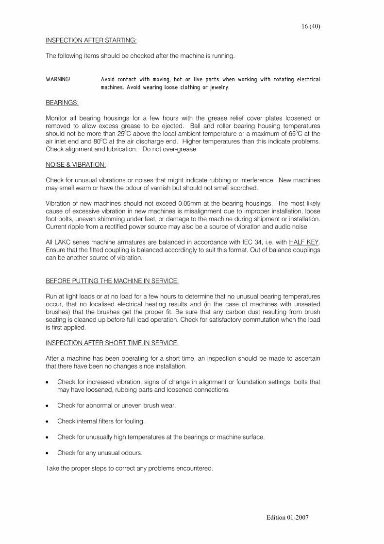
INSPECTION AFTER STARTING:
The following items should be checked after the machine is running.
WARNING! Avoid contact with moving, hot or live parts when working with rotating electricalmachines. Avoid wearing loose clothing or jewelry.
BEARINGS:
Monitor all bearing housings for a few hours with the grease relief cover plates loosened orremoved to allow excess grease to be ejected. Ball and roller bearing housing temperaturesshould not be more than 250C above the local ambient temperature or a maximum of 650C at theair inlet end and 800C at the air discharge end. Higher temperatures than this indicate problems.Check alignment and lubrication. Do not over-grease.
NOISE & VIBRATION:
Check for unusual vibrations or noises that might indicate rubbing or interference. New machinesmay smell warm or have the odour of varnish but should not smell scorched.
Vibration of new machines should not exceed 0.05mm at the bearing housings. The most likelycause of excessive vibration in new machines is misalignment due to improper installation, loosefoot bolts, uneven shimming under feet, or damage to the machine during shipment or installation.Current ripple from a rectified power source may also be a source of vibration and audio noise.
All LAKC series machine armatures are balanced in accordance with IEC 34, i.e. with HALF KEY.Ensure that the fitted coupling is balanced accordingly to suit this format. Out of balance couplingscan be another source of vibration.
BEFORE PUTTING THE MACHINE IN SERVICE:
Run at light loads or at no load for a few hours to determine that no unusual bearing temperaturesoccur, that no localised electrical heating results and (in the case of machines with unseatedbrushes) that the brushes get the proper fit. Be sure that any carbon dust resulting from brushseating is cleaned up before full load operation. Check for satisfactory commutation when the loadis first applied.
INSPECTION AFTER SHORT TIME IN SERVICE:
After a machine has been operating for a short time, an inspection should be made to ascertainthat there have been no changes since installation.
• Check for increased vibration, signs of change in alignment or foundation settings, bolts thatmay have loosened, rubbing parts and loosened connections.
• Check for abnormal or uneven brush wear.
• Check internal filters for fouling.
• Check for unusually high temperatures at the bearings or machine surface.
• Check for any unusual odours. Take the proper steps to correct any problems encountered.

17 (40)
Edition 01-2007
9. MAINTENANCE:
WARNING! The internal parts of a DC motor may be at line voltage even when the motor isnot rotating. Before attempting any maintenance that would result in contactingany internal part, ensure that the motor is disconnected from the power supply.
• Motors using rectified power sources - disconnect all ac line connections.
• Motors using rotating power source - disconnect all dc line, field and protectingcircuit connections.
GENERAL:
Check all nuts, bolts and fastenings are tight, all covers and guards are secure, and all electricalconnections are tight and secure.
CLEANLINESS:
Keep the interior and exterior of the motor(s) dry and clean. The interior should be kept free fromdust, dirt, corrosion, oil and moisture. Ensure that all ventilation openings are kept clear.
Where fitted, ventilation air filters, internal and external, must be kept clean or replaced to ensurefull volume of cooling air. When replacing filter elements check rubber gaskets are undamagedand are not distorted.
It is preferable to use a vacuum cleaner rather than a blower or airline to clean out motor interiors,as a blower is liable to drive the dirt into the motor windings instead of removing it. This caneventually lead to earth related faults on the motor windings.
BRUSH GEAR:
Periodically check that the carbon brushes move freely in the holders and that they are not wornbelow the recommended minimum brush length. Replace any broken carbon brushes.
Any accumulation of carbon dust at or around the brush gear should be removed.
Check that all brush ligaments and other connections are secure.
Check that the brush ligaments have not been distorted such that they prevent the brushes slidingin their holders.
When replacement of carbon brushes becomes necessary, use only replacements of the samegrade and quantity as those originally fitted. Refer to paragraph under maintenance for detailsdiagram of carbon brush and brush holder.
New brushes must be bedded to the commutator by applying the normal spring pressure andpassing a strip of glass paper backwards and forwards around the commutator surface. Ensurethat the rough surface of glass paper is towards the carbon brush.
After bedding, ensure that all carbon dust is removed by vacuum. Do not use compressed air.Keep carbon brushes and their holders clean.

18 (40)
Edition 01-2007
WARNING! High voltage and rotating machinery can cause serious or fatal injury. Brushesmust not be touched or replaced while the machine is energised or rotating.
COMMUTATOR:
Keep the commutator clean.
Under the correct condition the commutator will develop a healthy brown skin or ‘patina’. This isan ideal condition and the skin should not be removed.
To clean the commutator, wipe with a piece of canvas or other non-linting cloth. Do not use anysolvent, lubricants or abrasives unless abnormal conditions prevail.
Check for commutator wear and grooving/ridging. If this is of a minor nature then an abrasivecommutator stone may be used to restore the commutator surface. If the wear is excessive, thenthe armature should be removed and turned in a lathe to maintain concentricity, and the minimummaterials removed to restore the commutator surface.
After turning, clean between each commutator segment to remove all particles of copper. Under-cut the mica and bevel the segment edges as indicated in the sketch above.
0.5mm 2.0mm
60°
Carbon Brush
Brush Holder
Brush Spring

19 (40)
Edition 01-2007
COMMUTATOR TEMPERATURE:
For optimum brush life and ideal running conditions, the commutator operating temperatureshould be maintained between 600C and 1000C.
Temperatures above or below this level can lead to high brush wear and subsequent likelihood ofcarbon contamination of the windings.
This condition is more critical in machines with heat exchangers, especially when light loadingconditions accompany, or contribute to the low temperature of the commutator.
If this condition occurs contact Thrige-Scott Limited and advice will be given as to a remedy, onceall the site parameters have been assessed.
PRODUCTIVE MAINTENANCE:
Productive maintenance goes a step beyond preventative maintenance techniques. Productivemaintenance means that the maintenance should pay for itself in terms of less down time, moneysaved in repairing equipment, and more total production for each unit spent on maintenanceoperations.
• Keeping good records of machine data and setting up a means of recording maintenanceperformed and the measurements taken.
• Establishing a routine of measurements to be taken and inspection operations to beperformed. Without other experience to guide you, utilise the suggested maintenanceschedule that follows. Experience can be quickly built up by performing the inspections andmeasurements called for. These records will show whether or not various components of themachine change quickly or slowly. Maintenance schedules can be re-adjusted as experiencedictates. Making more frequent, elaborated inspections at first and carefully recording theresults will indicate the feel for important items and timing of critical inspection times. Set up aprogram to balance between spending more on maintenance and inspection than a failurewould cost.
In some cases, it is less expensive to repair or replace a part rather than to maintain it regularly.
A suggested schedule of routine maintenance operations and measurements is provided (seerecommended maintenance schedule). This time schedule may be modified as a record of experienceis built with equipment in particular applications. Machines on continuous process lines will havemore operating hours than intermittently run machines and will need more frequent attention.

20 (40)
Edition 01-2007
10. RECOMMENDED MAINTENANCE SCHEDULE
Adjust this schedule as necessary (guided by your records). It will show if more or less attention isjustified.
MONTHLY:
• BEARINGS:
Make sure that excessive grease or oil is not leaking out of the bearing housings, if anyleakage is present; correct the condition before continuing to operate. Accumulation of largeamounts of grease inside the motor should be cause for immediate concern. The bearingcap and metering plate (if fitted) should be pulled back to check for adequate grease fill insidethe metering plate.
• BALL AND ROLLER:
Listen to a few bearings on a sampled basis. Bearings that get progressively noisier will needreplacement at next shutdown.
• CARBON BRUSHES:
Check the brush length. Replace when minimum length has been exceeded. Inspect for wornor shiny brush clips, frayed or loose pigtails, chipped or broken brushes and cracked brushsprings. Remove a few brushes to check the brush-commutator contact face. Burned areasindicate commutator trouble. Loosen each brush in its holder. Blow out area of the holderand brush holder stud insulation with clean, dry air to remove brush dust. Wipe brush holderstud insulation to remove contamination.
WARNING! High voltage and rotating machinery can cause serious or fatal injury. Brushesmust not be touched or replaced while the machine is energised or rotating.
• COMMUTATORS:
Check the commutator for roughness by carefully feeling the brushes with a fibre stick.Jumping brushes give advanced warning of a commutator going rough. Observe thecommutator for signs of threading. Check for excessive commutator wear rate, streaking,copper drag, bar marking and heavy slot bar marking. Commutators should not have morethan 0.064mm bar-to-bar steps. Check commutator-running temperature.
• FILTERS:
Check internal and external filters for cleanliness. Clean or replace as necessary, ensuring thatthe gaskets, where fitted are undamaged and undistorted.
• INSULATION:
Perform a visual inspection. Measure and record insulation resistance values.

21 (40)
Edition 01-2007
SIX MONTHLY:
• BEARINGS:
Listen to all bearings. Pull back bearing cap and metering plate (if fitted) to inspect greaseconditions on a few representative machines.
• COMMUTATORS:
Check risers for cracks and dirt. If there are cracks, also check end of shaft keyway and shaftfan. (Cracks in this area mean extreme torsional vibration in system). Dirt should be clearedout of risers to maintain good ventilation.
• INSULATION:
Measure one-minute insulation resistance. Compare with records. Wipe deposits from brushholder stud insulation and commutator creepage path. Remove heavy deposits from aroundfield coil connections where earthing might occur. Blow deposits out of commutator riser areawith clean dry air. Blow out any blocked ventilation openings in windings. Make visualinspection for signs of over heating (dry, cracked, “roasted out” insulation and varnish).

22 (40)
Edition 01-2007
11. MECHANICAL:
BOLTS:
Check all electrical connections for tightness. Look for signs of poor connections (arcing,discoloration, and heat). Adjust inspection period to suit experience. Inspect foundation for signsof cracking and displaced foot shims; also check foot bolts for tightness. Check brush holders,brush holder studs, bracket bolts, etc., on a sampling basis. Check all coupling bolts. Check polebolt torque. Check tightness of vee ring commutator bolts. (This may be done yearly if justified byexperience.)
SHAFT:
Check corners of exposed end of shaft keyway for cracks (due to extreme torsional vibration). Ifthere are cracks check fan and commutator risers.
VENTILATION:
Check for clogged screens, louvres, external & internal filters, etc. When replacing filters, ensurethat the rubber gaskets are undamaged and not distorted.
VIBRATION:
Check for excessive vibration (more than 0.05 to 0.08mm), which will indicate change in balance oralignment.

23 (40)
Edition 01-2007
12. LUBRICATION:
Re-lubrication periods vary from six months to five years dependent on site conditions, degree ofoperating and ambient temperature. As a general rule, normal continuous running, eight hoursper day - re-grease every two years; running twenty-four hours per day - re-grease every twelvemonths. However, where machines are subjected to high ambient temperatures, and/or severeduty, more frequent lubrication, i.e. every six months is advisable.
When adding or renewing grease, ensure that only the correct or equivalent high quality grease isused.
Do not over grease, as excessive greasing causes churning, high temperature and subsequentlubrication failure.
Grease relief cover plates (if fitted) should be removed during regreasing to allow excess grease tobe ejected. These plates should be refitted after running the motor for a short period in order tomaintain the IP rating of the machine.
Under no circumstances should different types of grease be mixed in the same housing.
Lubrication data is supplied on the bearing detail plates fitted on both bearing housings.

24 (40)
Edition 01-2007
13. REPAIR:
Only qualified personnel, using the materials and processes for which the machine was designedshould make repairs. To protect the warranty during the warranty period, all repairs must be madeby an approved repair facility.
Many repairs can be easily performed with only assembly operations if replacement parts areavailable. If major repairs are undertaken (such as rewinding an armature), proper facilities shouldbe available and suitable precautions observed.
WARNING! When burning off old insulation materials or when welding near insulation duringrewinding, adequate ventilation must be provided to avoid exposing personnel tonoxious fumes. Combustion of exhaust fumes must be complete and adequatelyvented to the outside atmosphere.
WARNING! Exposure of personnel to airbourne inorganic fibres must be avoided by adequateventilation or by wetting the remaining insulation components following the burningoff of the organic materials.

25 (40)
Edition 01-2007
14. FAILURE:
WARNING! An extreme or prolonged overload or electrical failure may result in heating orarcing, which can cause the insulation to give off noxious fumes. All power shouldbe removed from the machine circuit as a precaution even though the circuit mayhave overload protection. Personnel should not approach the machine untiladequate ventilation of the area has purged the air of the fumes. When covers ofa machine are removed following a failure, care should be observed to avoidbreathing fumes from inside the machine. Preferably, time should be allowed forthe machine to cool before attempting any examination or repair. Failure toobserve these precautions may result in injury to personnel.
WARNING! Water should not be applied to any electrically energised equipment becauseelectric shock could result in serious or fatal injury. In case of fire, disconnect allpower from the equipment and use only a carbon dioxide (CO2) extinguisher toquench the flames. Before operating any machine after a suspected failure, itshould be inspected for damage. Remove covers and make a visual examination ofthe carbon brushes, commutator, connections and windings. Electrical tests ofeach winding to check for open or short circuits or earthing should also be made.Any arc damage should be cleaned up and repaired as necessary. Carbon brushesmay need re-seating before operation.

26 (40)
Edition 01-2007
15. DISMANTLING:
CAUTION! Safe practices for lifting and handling equipment should be followed. Hoists, slingsor chains of adequate capacity and in good repair only should be used.
ARMATURE REMOVAL:
SPECIAL TOOLS:
• Piping of approximately 1.5m in length, which will fit snugly to the drive end shaft extensionwhen the shaft is protected with heavy cardboard or other suitable material. Ensure the pipe issufficiently thick as not to bend when the armature is lifted.
• A wooden block of appropriate size to fit inside the commutator end of the machine and tosupport the armature during removal.
PROCEDURE:
• Clean exterior of the machine in order to prevent dirt, chips, etc., entering the machine interior.
• Remove carbon brushes from their holders and raise the holders from the commutatorsurface.
• Tape a piece of corrugated cardboard around the commutator surface to protect it duringhandling.
• Disconnect all cables leading from the brush gear assembly to the machine frame. Ensurecorrect labeling of these leads for re-assembly purposes. Label the brush arms and removefrom the rocker ring.
• On the outside, mark the endshield and frames. On the inside mark the rocker ring andendshield. Improper alignment of these parts on re-assembly will cause bad commutation.Remove shaft-earthing brush (if fitted).
• Remove outer bearing caps at both ends of the machine, leaving the metering plates on.
• Unbolt and remove the end shields at both ends and allow the armature to rest on the poles.The armature will need to be supported by a crane until the end shields are clear of the frame.
• Place the protective material around the drive end extension and put on the piping. Ensure thepiping is placed far enough along the shaft to prevent slippage. Place the wooden blockinside the commutator end endshield at the bottom to form a resisting surface at the samelevel as the pole.
• Lift armature until it is clears the poles on the bottom and slide a piece of protective materialinto the bottom air gap and across the wooden block, to protect the armature and give easeduring removal.
• Lift armature and remove via the commutator end by hoisting on the pipe and shaft at thecommutator end. Pull out until the core is resting on the wooden block. Disconnect sling onpipe and place around armature core whilst the armature is supported on the wooden block.Using both slings, again lift the armature and effect removal.
• Rest armature on vee-blocks, remove pipe and cover bearings with clean dry cloths. Do notput vee-blocks under armature glass bands or commutator.

27 (40)
Edition 01-2007
ARMATURE INSTALLATION:
• When a new or repaired armature is installed in an in place frame, in the reverse order of thearmature removal procedure, the following adjustments must be made:
• Marks showing the brush rocker ring position must be re-aligned.
• Brush holders must be adjusted to have a 3.0mm radial spacing from the commutator surface.When installing a replacement armature, which has a commutator larger than the original, itmay be necessary to move the brush holders radially away from the commutator surface toprevent damage during installation.
• Variations in manufacture may result in a condition that will require a slight shift in brush gearfrom the factory settings. Commutation under load should be observed following armaturereplacement and any unusual sparking, abnormal commutator film or segment burning shouldbe detected and corrected.

28 (40)
Edition 01-2007
ANTI-FRICTION BEARING REMOVAL:
• Clean the exterior of the machine to prevent dirt, chips, etc., from getting into the coupling,bearings or interior of the machine.
• Remove the armature from the frame.
• Remove the coupling hub if the unit is fitted with one. If the unit has a hydraulically removablecoupling, it should be removed according to the required procedure.
• Remove the outer bearing caps and endshields. Unbolt and remove the commutator-endgrease throw. Draw off the drive-end grease throw.
• Draw off the bearings as required.
ANTI-FRICTION BEARING REPLACEMENT:
If the old bearing is to be re-used, it should be cleaned and inspected to ensure that the bearing issuitable for further use. The following steps should be followed when reassembling a bearing:
• Ensure that the machine shaft and all parts being used have been cleaned to prevent dirt,chips, etc., from getting into the coupling, bearings or interior of the machine.
• Replace bearing inner caps.
• Pre-heat the bearing in an oil bath or induction heater to 1200C to 1300C.
• Assemble the heated bearings unto the shaft, ensuring that they fit tight up against the bearinglocation shoulders.
• Pre-heat the drive-end grease throw in an oil bath or induction heater to 1000C to 1200C.
• Assemble the drive-end grease throw unto the shaft ensuring that it fits tight up against thedrive-end bearing.
• When cool, grease the bearing using the quantity of grease annotated on the bearinginformation plate fixed to the endshield.
• Cover the bearings when re-assembling the machine following the re-assembly instructionsgiven above.
• When the machine has been re-assembled, the commutator-end grease throw can be boltedto the end of the shaft.
• Run the machine for several minutes to purge the excessive grease before replacing thegrease relief plates.

29 (40)
Edition 01-2007
16. GENERAL INSTALLATION, OPERATION AND MAINTENANCE INSTRUCTIONS FORAIR-WATER COOLED HEAT EXCHANGERS.
GENERAL:
Successful performance, length of service and ease of operation of heat transfer equipment aremainly dependent on the following factors:
• Manner of installation, including design of connecting pipe work.• Method of operation.• Thoroughness and frequency of cleaning.
Failure to perform properly may be due to one or more of the following:
• Heat exchangers being dirty.• Operating conditions being different from design conditions.• Air locking.• Incorrect piping connections.• Improper application.
INSTALLATION:
• Upon receipt of the heat exchanger inspect for damage. If there is damage, ensure that thecarrier is notified and information sent to Thrige Electric in writing immediately.
• Store under cover in a heated area where it will not be subjected to damage.• When installing, set the heat exchanger level and square, ensuring that the connections can
be made without force.• Allowance should be made when connection paperwork for expansion and contraction.• Ensure that all mating flanges between the cooler and the machine are adequately sealed
against the ingress of contamination.
WARNING! Water should not be applied to or allowed to come into contact with anyelectrically energised equipment because electric shock could result in serious orfatal injury.
WARNING! DC machines have characteristics, which can cause serious or fatal injury unlessthey are selected, installed, maintained and operated by qualified personnel familiarwith the special requirements of DC machines.
Disconnect power before touching any internal part. High voltage may be presenteven when the machine is not rotating. If used with a rectifier excitation supply,disconnect all ac line connections to the excitation source. Disconnect all dc fieldconnections. Failure to observe these precautions may result in injury topersonnel.
Installation should be in accordance with the National Electrical Regulations andconsistent with all local codes of practice. All exposed rotating parts such ascoupling; belt and chains should be guarded as necessary to prevent accidentalcontact with moving parts.
Machines accessible to the public should be further guarded by screening, guardrails, etc., to prevent the public from coming into contact with the equipment.Failure to observe these precautions may result in injury to personnel

30 (40)
Edition 01-2007
LIFTING:
Lifting shall be by means of the installed lifting lugs or eyes. It is the responsibility of the siteengineer to obtain approval for any other method of lifting. Refer to the rating plate or the drawingfor the weight of the equipment. Unless specifically detailed to the contrary lifting by the installedlugs or eyes is limited to the individual components supplied.
WARNING! Under no circumstances attempt to lift the combined weight of the heat exchangerand machine with the lifting lugs attached to the cooler. Failure to observe theseprecautions may result in damage to equipment, injury to personnel, or both.
OPERATION:
• Ensure that the entire system is clean before starting up to prevent internal fouling.
• Before starting ensure that all safety devices fitted are connected in circuit. All pressureswitches will have been pre-set before leaving the factory. All water flow switches or valvesmust be connected to the water outlet side of the system. Ensure that that the thermal probeof the water flow control valve (if fitted), is inserted into the pre-cooled air chamber at theopposite end of the cooler from the fan motor, above the commutator.
• Ensure that the water inlet/outlets are correctly connected. It is important that the water inletmust be to the BOTTOM pipe/flange and the outlet to the TOP pipe/flange, as the cooler isdesigned to take into effect that hot water rises.
• Remove ‘leak’ plug from bottom of exchanger - please note that this plug should be replacedbefore running the motor.
• Check the internal air circuit filters are clean and un-blocked.
• Ensure that the drain valve is closed.
• Open the air bleed valve to allow the cooler to fill with water and close once the coolant beginsto escape.
N.B. This operation should be repeated after a short period, to ensure removal of all of the air.
• Any water coming out of the ‘leak’ plughole indicates a possible leak in the cooling element. Ifno water is coming out, the plug should be replaced now.
• Start up operation gradually, every effort being made to avoid subjecting the units to thermalshock, over pressure, or hydraulic hammer.
• Cooling water should be circulated at the design flow rate before internal air fans are started.

31 (40)
Edition 01-2007
• Bolted joints should be re-tightened after the heat exchanger has reached operatingtemperature.
• Do not operate the heat exchanger under pressure and temperature conditions outside thosespecified on the rating plate.
WARNING! Should the machine be run for extended periods in a lightly loaded condition withfull flow water cooling, then it is likely that the motor will experience high brushwear due to low commutator temperatures combined with the low current density inthe brushes. As indicted above, the water volume control switch is fitted tocombat this condition. Should this not prove adequate or if there is no watervolume control switch fitted, then the quantity of brushes per brush arm should bereduced proportionally in relation to the actual motor running current against thefull load (rating plate) machine current. Alternatively, a brush grade suitable forlow temperature and/or low current density operation can be fitted. If in doubtcontact Thrige Electric.
MAINTENANCE:
Exchangers subjected to fouling should be cleaned as part of a regular maintenance schedule.The frequency of cleaning is dependent on the nature of coolant being used.
• INTERNAL FOULING:
This can range from a light slime coating to total blockage caused by a build up of corrosionproducts and deposits from the cooling water. Internal fouling may be treated in-situ if siteconditions permit. Tube-side conditions may initially be inspected via the connections afterthe unit has been drained of coolant and the pipe-work has been broken. Once the need forcleaning has been established, the full header plate may be removed to reveal the tube-plateand tubes. Typical slime deposits may be cleared using a rotary nylon brush. For heavierdeposits, a high-pressure water jet with a suitably designed nozzle may prove more effective.With the correct choice of nozzle, almost any amount of internal fouling may be removed.The flow channels of associated valves, strainers and filters should also be inspected on aregular basis.
• EXTERNAL FOULING:
This arises from pollution of the air circuit. This type of fouling may range from dry dust andairborne fibrous matter to oily deposits which are adherent. Treatment of this problem usuallynecessitates removal of the unit from its surrounding ductwork. The extended surface of aheat exchanger is relatively insensitive to fouling due to the low conductivity of air and thehigh surface areas being used. Typical fouling factors represent approximately 1% of theexternal heat transfer coefficient. Cleaning of the external surface is necessary, therefore, notso much to improve the heat transfer, as to prevent obstruction of the airflow. Increasedresistance to airflow can result in a reduced air circulation. This adversely affects the overallcapacity of the unit. Dry deposits may be removed using a compressed air jet. Morestubborn deposits may be removed with the aid of an industrial detergent.

32 (40)
Edition 01-2007
DAMAGED TUBES:
Should a tube bundle leak, the damage may take one of several forms. Each requires a differentprocedure to effect repair.
• Leakage at the tube-plate is generally caused by the loosening of an expanded tube. This canbe cured by further expansion of the tube into the tube-plate.
• Fracture at some point along the tube length without server distortion of the tube. Such tubescan be lined with a secondary tube that is inserted once the tube bore has been thoroughlycleaned. The liner is then expanded into the damaged tube to seal the leak and permit alimited amount of flow to be maintained.
• Fracture with the tube distortion must be repaired by use of tube plugs. A ring and pin typeplug is inserted and expanded into each end of the damaged tube. This can also be used incases of tube damage covered in paragraph above.
DAMAGED FINS:
If this occurs without damage to the base tube, careful use of long nosed pliers or a similar tubeshould effect straightening of the fins.
SPARES:
Equipment described in the above maintenance instructions, including tube expanders, liners andplugs, can be supplied in the form of a spares kit to suit the requirements of the cooler supplied.
ANCILLARY EQUIPMENT:
• Full flow air filter.• Internal air fan.• Water flow indicator.• Air pressure switch.

33 (40)
Edition 01-2007
17. GENERAL INSTALLATION, OPERATION AND MAINTENANCE INSTRUCTIONS FOR AIR-AIR COOLED HEAT EXCHANGERS.
GENERAL:
Successful performance, length of service and ease of operation of heat transfer equipment aremainly dependent on the following factors:
• Manner of installation.• Method of operation.• Thoroughness and frequency of cleaning.
Failure to perform properly may be due to one or more of the following:
• Heat exchangers being dirty.• Operating conditions being different from design conditions.• Air locking.• Improper application.
INSTALLATION:
• Upon receipt of the heat exchanger inspect for damage. If this is evident, notify the supplierimmediately.
• Store under cover in a heated area where it will not be subjected to damage.
• When installing, set the heat exchanger level and square, ensuring that the connections canbe made without force.
• Before starting ensure that all safety devices fitted are connected in circuit. All pressureswitches will have been pre-set before leaving the factory.
• Where emergency doors are fitted, these should be checked for freedom of movement andcorrect location in the open and closed positions.
• Ensure that all mating flanges between the cooler and the motor are adequately sealedagainst the ingress of contamination.
WARNING! DC machines have characteristics that can cause serious or fatal injury unless theyare selected, installed, maintained and operated by qualified personnel familiar withthe special requirements of DC machines.
Disconnect power before touching any internal part. High voltage may be presenteven when the machine is not rotating. If used with a rectifier excitation supply,disconnect all ac line connections to the excitation source. Disconnect all dc fieldconnections. Failure to observe these precautions may result in injury topersonnel.
Installation should be in accordance with the National Electrical Regulations andconsistent with all local codes of practice. All exposed rotating parts such ascoupling; belt and chains should be guarded as necessary to prevent accidentalcontact with moving parts. Machines accessible to the public should be further guarded by screening, guardrails, etc., to prevent the public from coming into contact with the equipment.Failure to observe these precautions may result in injury to personnel.

34 (40)
Edition 01-2007
LIFTING:
Lifting shall be by means of the installed lifting lugs or eyes. It is the responsibility of the siteengineer to obtain approval for any other method of lifting. Refer to the nameplate or the drawingfor the weight of the equipment. Unless specifically detailed to the contrary lifting by the installedlugs or eyes is limited to the individual components supplied.
WARNING! Under no circumstances attempt to lift the combined weight of the heat exchangerand motor with the lifting lugs attached to the cooler.
Failure to observe these precautions may result in damage to equipment, injury topersonnel, or both.
INSTALLATION:
Having confirmed cleanliness after receipt or removal from storage the equipment should bemounted making all connections without force or distortion. Closures and supports used forhandling and transport purposes must be removed.
Dependent upon operating temperature equipment may expand considerably. Ductwork designmust allow for the relative movement of gas connections and as with other types of heatexchangers supports must also be designed to allow free expansion.
OPERATING AND MAINTENANCE:
To maintain the operational efficiency of the heat exchanger the air passages should be examinedand periodically cleaned if necessary. The frequency of cleaning will depend on the environmentand the nature of any fouling occurring. Indications of fouling of the heat transfer services aretypically, an increase in the system pressure drop, reduction in air volumes circulated andreductions in thermal performance. The way in which fouling will manifest itself will depend uponthe plant control.
Light deposits may be removed from the tubes using non-metallic brushes. Care should be takento avoid damage to corrosion protective coatings caused by excessive force and abrasion beingused. Detergent and water may be a useful aid in removing stubborn deposits.
For heavy fouling high-pressure water jetting is recommended where there is no tube borecoatings. Even the most stubborn deposits may be removed by this method, which avoids theproblem of tube bore scoring encountered with other mechanical methods.
ANCILLARY COMPONENTS:
CACA heat exchangers can be supplied with the following ancillary components:
• Fan, for circulating internal air.• Fan, for external cooling air.• Air filter, on internal air circuit.• Air pressure switches.

35 (40)
Edition 01-2007
18. INTERNAL AIR CIRCUIT FILTERS – AIR-AIR & AIR-WATER COOLERS
These filters are to EU9 specification.
They should be replaced regularly to maintain the cooling airflow within the machine and toprevent overheating.
REMOVAL OF AIR FILTERS FROM AIR-AIR & AIR-WATER COOLERS
• Remove filter access cover.
• Cover hole inside base of cooler to prevent dirt or tools falling into motor.
• Undo filter clamps.
• Remove filter panel for renewal.
• Use vacuum cleaner to remove all dust from inside the cooler.
• Re-fit new filter panel and clamp into position.
• Remove the cover used to prevent dirt or tools falling into motor.
• Ensure that the inside of the cooler is thoroughly clean.
• Re-fit filter access cover unto cooler.

36 (40)
Edition 01-2007
19. MOTOR PROBLEMS - QUICK CHECKLIST
SYMPTOM: POSSIBLE CAUSE:
MECHANICAL:
Bearing overheats: Excessive grease in bearing.Dirt in bearings.Bearing clearance too small.Lubrication failure.Incorrect grease used.Misalignment.Excessive belt tension.
Bearing knocks: Dirt in bearing.Bearing clearance too large.Defect in bearing surface.Bearing wrongly fitted
Bearing whistles: Bearing clearance too small.
Bearing requires early Dirt in bearing.Renewal: Defect in bearing surface.
Bearing wrongly fitted.Lubrication failure.Misalignment.Excessive belt tension.
ELECTRICAL:
Motor will not start: Brushes making bad contact.Break in armature supply.Fault in field supply.
Motor only just starts: Short circuit on armature winding.Fault in field circuit.
Motor runs to fast or too slow: Brush position wrong. Fault in field supply.
Short circuit on field winding.
Motor overheats: Overloading.Ventilation obstruction.External or internal air circuit filter blocked.Ventilation failure.Short circuit on armature winding.

37 (40)
Edition 01-2007
MOTOR PROBLEMS - QUICK CHECKLIST
SYMPTOM: POSSIBLE CAUSE:
COMMUTATION
Sparking: Overloading.Broken brush(es)Brush sticking in holder.Brush position wrong.Dirty or corroded commutator.Commutator surface contaminated by oil, oil-mist, orother ambient factors.Low commutator temperature.High mica.Loss of brush spring tension.Short circuit on armature winding.Short circuit on Interpole winding.
Sparking and noisy operation of Short circuit between adjacent commutator segments.brushes on commutator: High resistance connection at commutator.
High mica.Loose commutator.
Sparking, rough commutator surface, fine lines in brush track:
Low average current density in brushes due to lightmotor loading.Commutator surface contaminated by oil, oil-mist, orother ambient factors.Low humidity.Commutator operating temperature to low.Loss of brush spring tension.
Rapid commutator or brush wear: Abrasive material under brush.Brush grade too abrasive.Low average current density in brushes due to lightmotor loading.
Blackening of commutator at Commutator segment short circuit.certain spots: Motor being stalled.
Mechanical vibration.
38 (40)
Edition 01-2007
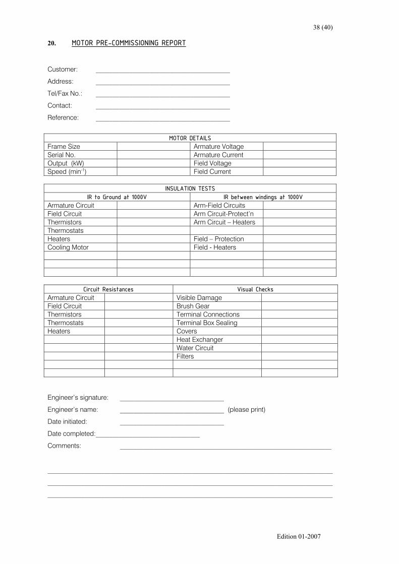
20. MOTOR PRE-COMMISSIONING REPORT
Customer: ________________________________________
Address: ________________________________________
Tel/Fax No.: ________________________________________
Contact: ________________________________________
Reference: ________________________________________
MOTOR DETAILSFrame Size Armature VoltageSerial No. Armature CurrentOutput (kW) Field VoltageSpeed (min-1) Field Current
INSULATION TESTSIR to Ground at 1000V IR between windings at 1000V
Armature Circuit Arm-Field CircuitsField Circuit Arm Circuit-Protect’nThermistors Arm Circuit – HeatersThermostatsHeaters Field – ProtectionCooling Motor Field - Heaters
Circuit Resistances Visual ChecksArmature Circuit Visible DamageField Circuit Brush GearThermistors Terminal ConnectionsThermostats Terminal Box SealingHeaters Covers
Heat ExchangerWater CircuitFilters
Engineer’s signature: _______________________________
Engineer’s name: _______________________________ (please print)
Date initiated: _______________________________
Date completed:_______________________________
Comments: _______________________________________________________________
_____________________________________________________________________________________
_____________________________________________________________________________________
_____________________________________________________________________________________

39 (40)
Edition 01-2007

40 (40)
Edition 01-2007
MOTOR COMMISSIONING REPORT
Customer: ________________________________________
Tel/Fax No.: ________________________________________
Contact: ________________________________________
Reference: ________________________________________
MOTOR DETAILSFrame Size Armature VoltageSerial No. Armature CurrentOutput (kW) Field VoltageSpeed (min-1) Field Current
PRE RUNNINGAlignmentBolted downConnectionsCovers fitted
RUNNING OFF LOADCooling motor directionCooling motor current
Field voltageField currentArmature voltageArmature currentSpeed (min-1)Direction (from DE)
Vibration level
RUNNING ON LOADField voltageField currentArmature voltageArmature current
Speed (min-1)Vibration level
Engineer’s signature: _______________________________
Engineer’s name: _______________________________ (please print)
Date initiated: _______________________________
Date completed:_______________________________
Comments: _______________________________________________________________

41 (40)
Edition 01-2007
MOTOR MAINTENANCE REPORT
Customer: ________________________________________
Address: ________________________________________
Tel/Fax No.: ________________________________________
Contact: ________________________________________
Reference: ________________________________________
MOTOR DETAILSFrame Size Armature VoltageSerial No. Armature CurrentOutput (kW) Field VoltageSpeed (min-1) Field Current
INSULATION TESTSIR to Ground at 1000V IR between windings at 1000V
Armature Circuit Arm-Field CircuitsField Circuit Arm Circuit-Protect’nThermistors Arm Circuit – HeatersThermostatsHeaters Field – ProtectionCooling Motor Field - Heaters
Brush Grade: Brush arm numbering: Top = 1, number CW viewed at Comm-EndBrush holder numbering: Riser = 1, number towards endshield
BRUSH LENGTH RECORD CHARTBrush HolderDate Brush Arm
1 2 3 4 5 6 7Comments
12345678
BRUSH LENGTH RECORD CHARTBrush HolderDate Brush Arm
1 2 3 4 5 6 7Comments
12345678