Embed Size (px)
Citation preview

UPS3000 LV and UPS3000 HV
Installation and Maintenance Guide
���


UPS3000 LV and UPS3000 HV
Installation and Maintenance Guide
���

Before using this information and the product it supports, read the general information in Appendix B, “IBM Statement of Limited
Warranty Z125-4753-08 04/2004,” on page 45 and Appendix C, “Notices,” on page 63.
Third Edition (July 2008)
© Copyright International Business Machines Corporation 2006, 2008. All rights reserved.
US Government Users Restricted Rights – Use, duplication or disclosure restricted by GSA ADP Schedule Contract
with IBM Corp.

Safety
Before installing this product, read the Safety Information.
Antes de instalar este produto, leia as Informações de Segurança.
Pred instalací tohoto produktu si prectete prírucku bezpecnostních instrukcí.
Læs sikkerhedsforskrifterne, før du installerer dette produkt.
Lees voordat u dit product installeert eerst de veiligheidsvoorschriften.
Ennen kuin asennat tämän tuotteen, lue turvaohjeet kohdasta Safety Information.
Avant d’installer ce produit, lisez les consignes de sécurité.
Vor der Installation dieses Produkts die Sicherheitshinweise lesen.
Prima di installare questo prodotto, leggere le Informazioni sulla Sicurezza.
Les sikkerhetsinformasjonen (Safety Information) før du installerer dette produktet.
Antes de instalar este produto, leia as Informações sobre Segurança.
© Copyright IBM Corp. 2006, 2008 iii

Antes de instalar este producto, lea la información de seguridad.
Läs säkerhetsinformationen innan du installerar den här produkten.
Important:
Each caution and danger statement in this document is labeled with a number. This
number is used to cross reference an English-language caution or danger
statement with translated versions of the caution or danger statement in the Safety
Information document.
For example, if a caution statement is labeled “Statement 1,” translations for that
caution statement are in the Safety Information document under “Statement 1.”
Be sure to read all caution and danger statements in this document before you
perform the procedures. Read any additional safety information that comes with the
server or optional device before you install the device.
iv UPS 3000 LV and UPS3000 HV: Installation and Maintenance Guide
DANGER
When working on or around the system, observe the following precautions:
Electrical voltage and current from power, telephone, and communication
cables are hazardous. To avoid a shock hazard:
v Connect power to this unit only with the provided power cord. Do not
use the provided power cord for any other product.
v Do not open or service any power supply assembly.
v Do not connect or disconnect any cables or perform installation,
maintenance, or reconfiguration of this product during an electrical
storm.
v The product might be equipped with multiple power cords. To remove all
hazardous voltages, disconnect all power cords.
v Connect all power cords to a properly wired and grounded electrical
outlet. Ensure that the outlet supplies proper voltage and phase rotation
according to the system rating plate.
v Connect any equipment that will be attached to this product to properly
wired outlets.
v When possible, use one hand only to connect or disconnect signal
cables.
v Never turn on any equipment when there is evidence of fire, water, or
structural damage.
v Disconnect the attached power cords, telecommunications systems,
networks, and modems before you open the device covers, unless
instructed otherwise in the installation and configuration procedures.
v Connect and disconnect cables as described in the following procedures
when installing, moving, or opening covers on this product or attached
devices.
To disconnect:
1. Turn off everything (unless instructed otherwise).
2. Remove the power cords from the outlets.
3. Remove the signal cables from the connectors.
4. Remove all cables from the devices.
To connect:
1. Turn off everything (unless instructed otherwise).
2. Attach all cables to the devices.
3. Attach the signal cables to the connectors.
4. Attach the power cords to the outlets.
5. Turn on the devices.
(D005a)
Safety v

CAUTION:
Lead-acid batteries can present a risk of electrical burn from high,
short-circuit current. Avoid battery contact with metal materials; remove
watches, rings, or other metal objects, and use tools with insulated handles.
To avoid possible explosion, do not burn.
Exchange only with the IBM-approved part. Recycle or discard the battery as
instructed by local regulations. In the United States, IBM has a process for
the collection of this battery. For information, call 1-800-426-4333. Have the
IBM part number for the battery unit available when you call. (C004)
CAUTION:
or
>32 kg (70.5 lb)
or
32-55 kg (70.5-121.2 lb)
The weight of this part or unit is between 32 and 55 kg (70.5 and 121.2 lb). It
takes three persons to safely lift this part or unit. (C010)
DANGER
Hazardous voltage, current, or energy levels are present inside any
component that has this label attached. Do no open any cover or barrier
that contains this label.
(L001)
vi UPS 3000 LV and UPS3000 HV: Installation and Maintenance Guide

The following general safety information should be used for all rack-mounted
devices:
DANGER
Observe the following precautions when working on or around your IT rack
system:
v Heavy equipment—personal injury or equipment damage might result if
mishandled.
v Always lower the leveling pads on the rack cabinet.
v Always install stabilizer brackets on the rack cabinet.
v To avoid hazardous conditions due to uneven mechanical loading,
always install the heaviest devices in the bottom of the rack cabinet.
Always install servers and optional devices starting from the bottom of
the rack cabinet.
v Rack-mounted devices are not to be used as shelves or work spaces. Do
not place objects on top of rack-mounted devices.
v Each rack cabinet might have more than one power cord. Be sure to
disconnect all power cords in the rack cabinet when directed to
disconnect power during servicing.
v Connect all devices installed in a rack cabinet to power devices installed
in the same rack cabinet. Do not plug a power cord from a device
installed in one rack cabinet into a power device installed in a different
rack cabinet.
v An electrical outlet that is not correctly wired could place hazardous
voltage on the metal parts of the system or the devices that attach to the
system. It is the responsibility of the customer to ensure that the outlet
is correctly wired and grounded to prevent an electrical shock.
(R001 part 1 of 2)
Safety vii
CAUTION:
v Do not install a unit in a rack where the internal rack ambient temperatures
will exceed the manufacturer’s recommended ambient temperature for all
your rack-mounted devices.
v Do not install a unit in a rack where the air flow is compromised. Ensure
that air flow is not blocked or reduced on any side, front, or back of a unit
used for air flow through the unit.
v Consideration should be given to the connection of the equipment to the
supply circuit so that overloading of the circuits does not compromise the
supply wiring or overcurrent protection. To provide the correct power
connection to a rack, refer to the rating labels located on the equipment in
the rack to determine the total power requirement of the supply circuit.
v (For sliding drawers) Do not pull out or install any drawer or feature if the
rack stabilizer brackets are not attached to the rack. Do not pull out more
than one drawer at a time. The rack might become unstable if you pull out
more than one drawer at a time.
v (For fixed drawers) This drawer is a fixed drawer and must not be moved
for servicing unless specified by the manufacturer. Attempting to move the
drawer partially or completely out of the rack might cause the rack to
become unstable or cause the drawer to fall out of the rack.
(R001 part 2 of 2)
viii UPS 3000 LV and UPS3000 HV: Installation and Maintenance Guide

Contents
Safety . . . . . . . . . . . . . . . . . . . . . . . . . . . . iii
Chapter 1. Introduction . . . . . . . . . . . . . . . . . . . . . . 1
The IBM Documentation CD . . . . . . . . . . . . . . . . . . . . 1
Hardware and software requirements . . . . . . . . . . . . . . . . 1
Using the Documentation Browser . . . . . . . . . . . . . . . . . 2
Specifications . . . . . . . . . . . . . . . . . . . . . . . . . . 3
Notices and statements in this document . . . . . . . . . . . . . . . . 4
Chapter 2. Installing the uninterruptible power supply in a rack or tower
configuration . . . . . . . . . . . . . . . . . . . . . . . . . 5
Inventory checklist . . . . . . . . . . . . . . . . . . . . . . . . 5
Rack configuration . . . . . . . . . . . . . . . . . . . . . . . . 5
Tower configuration . . . . . . . . . . . . . . . . . . . . . . . . 6
Setting up the uninterruptible power supply (with no extended battery module) 7
Setting up the uninterruptible power supply with one extended battery module 8
Setting up the uninterruptible power supply with two or more extended battery
modules . . . . . . . . . . . . . . . . . . . . . . . . . . 9
Connecting the internal battery . . . . . . . . . . . . . . . . . . . 10
Connecting the uninterruptible power supply to the extended battery modules
(rack configuration) . . . . . . . . . . . . . . . . . . . . . . 11
Connecting the uninterruptible power supply to the extended battery modules
(tower configuration) . . . . . . . . . . . . . . . . . . . . . . 12
Completing the installation . . . . . . . . . . . . . . . . . . . . . 13
Remote emergency power-off installation . . . . . . . . . . . . . . . 14
Chapter 3. Uninterruptible power supply controls, LEDs, operating modes,
and power . . . . . . . . . . . . . . . . . . . . . . . . . 17
Front view . . . . . . . . . . . . . . . . . . . . . . . . . . 17
Rear view . . . . . . . . . . . . . . . . . . . . . . . . . . . 18
Operating modes . . . . . . . . . . . . . . . . . . . . . . . . 18
Normal mode . . . . . . . . . . . . . . . . . . . . . . . . 19
Battery mode . . . . . . . . . . . . . . . . . . . . . . . . 19
Bypass mode . . . . . . . . . . . . . . . . . . . . . . . . 19
Standby mode . . . . . . . . . . . . . . . . . . . . . . . . 19
Configuration mode . . . . . . . . . . . . . . . . . . . . . . 20
Turning on the uninterruptible power supply . . . . . . . . . . . . . . 22
Starting the uninterruptible power supply on battery . . . . . . . . . . . 22
Turning off the uninterruptible power supply . . . . . . . . . . . . . . 22
Load segments . . . . . . . . . . . . . . . . . . . . . . . . . 23
Chapter 4. Using the Web/SNMP card . . . . . . . . . . . . . . . . 25
Introduction . . . . . . . . . . . . . . . . . . . . . . . . . . 25
System application . . . . . . . . . . . . . . . . . . . . . . . 26
Web/SNMP card LEDs and controls . . . . . . . . . . . . . . . . . 27
Configuring the Web/SNMP card locally . . . . . . . . . . . . . . . . 27
Before you begin . . . . . . . . . . . . . . . . . . . . . . . 27
Connecting the card to a terminal or computer . . . . . . . . . . . . 28
Configuring the Web/SNMP card . . . . . . . . . . . . . . . . . 28
Set the IP address, gateway address, and MIB system group . . . . . . . 29
Set Web/SNMP card control group . . . . . . . . . . . . . . . . 30
Set write access managers . . . . . . . . . . . . . . . . . . . 30
Set trap receivers . . . . . . . . . . . . . . . . . . . . . . . 30
© Copyright IBM Corp. 2006, 2008 ix
Set IP addresses of primary and secondary date server . . . . . . . . . 30
UPS event actions . . . . . . . . . . . . . . . . . . . . . . 30
Set UPS information . . . . . . . . . . . . . . . . . . . . . . 31
Set superuser name and password . . . . . . . . . . . . . . . . 31
Email notification . . . . . . . . . . . . . . . . . . . . . . . 31
Set Web site links . . . . . . . . . . . . . . . . . . . . . . . 31
Card settings and event log summary . . . . . . . . . . . . . . . 31
Set external contact monitoring . . . . . . . . . . . . . . . . . . 31
Remote configuration . . . . . . . . . . . . . . . . . . . . . . 32
Adding a routing condition in the computer . . . . . . . . . . . . . . 32
Opening the Web interface . . . . . . . . . . . . . . . . . . . 32
Setting up the network configuration . . . . . . . . . . . . . . . . 32
Using the Web/SNMP card in Serial Pass-through mode . . . . . . . . . 33
Chapter 5. Hardware maintenance information . . . . . . . . . . . . 35
Replaceable uninterruptible power supply components . . . . . . . . . . 35
Uninterruptible power supply and battery care . . . . . . . . . . . . . 35
Storing the uninterruptible power supply and batteries . . . . . . . . . . 36
Replacing the electronics module (for trained service technician only) . . . . . 36
Replacing the battery module (for trained service technicians only) . . . . . . 37
Chapter 6. Troubleshooting . . . . . . . . . . . . . . . . . . . . 39
Audible alarms and uninterruptible power supply conditions . . . . . . . . 39
Troubleshooting guide . . . . . . . . . . . . . . . . . . . . . . 39
Appendix A. Getting help and technical assistance . . . . . . . . . . 43
Before you call . . . . . . . . . . . . . . . . . . . . . . . . . 43
Using the documentation . . . . . . . . . . . . . . . . . . . . . 43
Getting help and information from the World Wide Web . . . . . . . . . . 43
Software service and support . . . . . . . . . . . . . . . . . . . 44
Hardware service and support . . . . . . . . . . . . . . . . . . . 44
IBM Taiwan product service . . . . . . . . . . . . . . . . . . . . 44
Appendix B. IBM Statement of Limited Warranty Z125-4753-08 04/2004 45
Part 1 - General Terms . . . . . . . . . . . . . . . . . . . . . . 45
Part 2 - Country-unique Terms . . . . . . . . . . . . . . . . . . . 48
Part 3 - Warranty Information . . . . . . . . . . . . . . . . . . . 60
Appendix C. Notices . . . . . . . . . . . . . . . . . . . . . . 63
Trademarks . . . . . . . . . . . . . . . . . . . . . . . . . . 63
Important notes . . . . . . . . . . . . . . . . . . . . . . . . . 64
Product recycling and disposal . . . . . . . . . . . . . . . . . . . 65
Battery return program . . . . . . . . . . . . . . . . . . . . . . 66
Electronic emission notices . . . . . . . . . . . . . . . . . . . . 68
Federal Communications Commission (FCC) statement . . . . . . . . . 68
Industry Canada Class A emission compliance statement . . . . . . . . 68
Avis de conformité à la réglementation d’Industrie Canada . . . . . . . . 68
Australia and New Zealand Class A statement . . . . . . . . . . . . 68
United Kingdom telecommunications safety requirement . . . . . . . . . 68
European Union EMC Directive conformance statement . . . . . . . . . 68
Taiwanese Class A warning statement . . . . . . . . . . . . . . . 69
Chinese Class A warning statement . . . . . . . . . . . . . . . . 69
Japanese Voluntary Control Council for Interference (VCCI) statement . . . 69
Korean Class A warning statement . . . . . . . . . . . . . . . . 70
Index . . . . . . . . . . . . . . . . . . . . . . . . . . . . 71
x UPS 3000 LV and UPS3000 HV: Installation and Maintenance Guide
Chapter 1. Introduction
The IBM® UPS3000 LV (low voltage) and UPS3000 HV (high voltage) models are
designed to prevent blackouts, brownouts, sags, and surges from reaching your
servers and other valuable electronic equipment. The uninterruptible power supply
filters small utility line fluctuations and isolates your equipment from large
disturbances by internally disconnecting from the utility line. The uninterruptible
power supply provides continuous power from its internal battery until the utility line
returns to safe levels or the battery is fully discharged. This document contains the
following information:
v Setting up the uninterruptible power supply
v Starting and configuring the uninterruptible power supply
v Solving problems
If firmware and documentation updates are available, you can download them from
http://www.ibm.com/support/. The uninterruptible power supply might have features
that are not described in the documentation that comes with the uninterruptible
power supply, and the documentation might be updated occasionally to include
information about those features, or technical updates might be available to provide
additional information that is not included in the uninterruptible power supply
documentation. To check for updates, go to http://www.ibm.com/support/. For
firmware updates, click Downloads and drivers. For documentation updates, under
Search technical support, type 2130, and click Search.
Note: Changes are made periodically to the IBM Web site. Procedures for locating
firmware and documentation might vary slightly from what is described in this
document.
The uninterruptible power supply comes with a limited warranty. See Appendix B,
“IBM Statement of Limited Warranty Z125-4753-08 04/2004,” on page 45.
See the Rack Installation Instructions document for complete rack installation and
removal instructions.
Note: The illustrations in this document might differ slightly from your hardware.
The IBM Documentation CD
The IBM Documentation CD contains documentation for your uninterruptible power
supply in Portable Document Format (PDF) and includes the IBM Documentation
Browser to help you find information quickly.
Hardware and software requirements
The IBM Documentation CD requires the following minimum hardware and
software:
v Microsoft® Windows NT® 4.0 (with Service Pack 3 or later), Windows® 2000, or
Red Hat® Linux®.
v 100 MHz microprocessor.
v 32 MB of RAM.
v Adobe Acrobat Reader 3.0 (or later) or xpdf, which comes with Linux operating
systems. Acrobat Reader software is included on the CD, and you can install it
when you run the Documentation Browser.
© Copyright IBM Corp. 2006, 2008 1

Using the Documentation Browser
Use the Documentation Browser to browse the contents of the CD, read brief
descriptions of the documents, and view documents, using Adobe Acrobat Reader
or xpdf. The Documentation Browser automatically detects the regional settings in
use in your computer and displays the documents in the language for that region (if
available). If a document is not available in the language for that region, the
English-language version is displayed.
Use one of the following procedures to start the Documentation Browser:
v If Autostart is enabled, insert the CD into the CD drive. The Documentation
Browser starts automatically.
v If Autostart is disabled or is not enabled for all users, use one of the following
procedures:
– If you are using a Windows operating system, insert the CD into the CD drive
and click Start --> Run. In the Open field, type
e:\win32.bat
where e is the drive letter of the CD drive, and click OK.
– If you are using Red Hat Linux, insert the CD into the CD drive; then, run the
following command from the /mnt/cdrom directory:
sh runlinux.sh
Select your uninterruptible power supply from the Product menu. The Available
Topics list displays all the documents for your uninterruptible power supply. Some
documents might be in folders. A plus sign (+) indicates each folder or document
that has additional documents under it. Click the plus sign to display the additional
documents.
When you select a document, a description of the document is displayed under
Topic Description. To select more than one document, press and hold the Ctrl key
while you select the documents. Click View Book to view the selected document or
documents in Acrobat Reader or xpdf. If you selected more than one document, all
the selected documents are opened in Acrobat Reader or xpdf.
To search all the documents, type a word or word string in the Search field and
click Search. The documents in which the word or word string is displayed are
listed in order of the most occurrences. Click a document to view it, and press
Crtl+F to use the Acrobat search function or Alt+F to use the xpdf search function
within the document.
Click Help for detailed information about using the Documentation Browser.
2 UPS 3000 LV and UPS3000 HV: Installation and Maintenance Guide

Specifications
The specifications of the uninterruptible power supply are shown in the following
table.
Table 1. UPS3000 LV and UPS3000 HV specifications
UPS3000 LV UPS3000 HV
Height 89 mm (3.5 in.) 89 mm (3.5 in.)
Width 482.6 mm (19.0 in.) 482.6 mm (19.0 in.)
Depth 622.3 mm (24.5 in.) 622.3 mm (24.5 in.)
Additional clearance 25 mm (0.98 in.) for circuit
breakers
3 mm (0.12 in.) for outlets
25 mm (0.98 in.) for circuit
breakers
3 mm (0.12 in.) for outlets
Weight 37.0 kg (82.0 lb) 37.0 kg (82.0 lb)
Operating temperature at
0 to 3000 m (0 to 10 000
ft)
0° to 40°C (32° to 104°F) 0° to 40°C (32° to 104°F)
Maximum operating
altitude
2000 m (6562 ft) 2000 m (6562 ft)
Relative humidity 0 to 95% noncondensing 0 to 95% noncondensing
Nominal input voltage 120 V 220 V ac (selectable from
200 - 240 V ac)
Maximum input current 30 amps 16 amps
Input voltage range for
main operations
90 to 144 V 160 to 288 V
Input voltage adjustable
range for main operations
77 to 152 V 154 to 288 V
Nominal output voltage 120 V 220 V, configurable for 200,
220, 230, or 240 V
Input frequency 50/60 Hz ± 4 Hz (auto sensing) 50/60 Hz ± 4 Hz (auto
sensing)
Rated power output 2880 VA 3000 VA
Output power capacity in
watts
2700 W 2700 W
Circuit breakers Three supplemental circuit
breakers rated at 15 amps, one
for each load segment
Three supplemental circuit
breakers rated at 15 amps,
one for each load segment
Fixed power cord Length: 12 ft; Nema L5-30P
connection to source
Input connection type IEC-320 C20, connection to
source using country
specific power cords
Power outlets One L5-30R outlet
Six 5-15R outlets
Six IEC C13 outlets
One IEC C19 outlet
Audible noise at 1 meter <45 dBA normal
<50 dBA Battery mode
<45 dBA normal
<50 dBA Battery mode
Online thermal dissipation 171 Btu per hour 171 Btu per hour
Chapter 1. Introduction 3

Notices and statements in this document
The caution and danger statements in this document are also in the multilingual
Safety Information document, which is on the IBM Documentation CD. Each
statement is numbered for reference to the corresponding statement in the Safety
Information document.
The following notices and statements are used in this document:
v Note: These notices provide important tips, guidance, or advice.
v Important: These notices provide information or advice that might help you avoid
inconvenient or problem situations.
v Attention: These notices indicate potential damage to programs, devices, or
data. An attention notice is placed just before the instruction or situation in which
damage could occur.
v Caution: These statements indicate situations that can be potentially hazardous
to you. A caution statement is placed just before the description of a potentially
hazardous procedure step or situation.
v Danger: These statements indicate situations that can be potentially lethal or
extremely hazardous to you. A danger statement is placed just before the
description of a potentially lethal or extremely hazardous procedure step or
situation.
4 UPS 3000 LV and UPS3000 HV: Installation and Maintenance Guide

Chapter 2. Installing the uninterruptible power supply in a
rack or tower configuration
This chapter describes the following tasks:
v Checking the package contents
v Installing the uninterruptible power supply in a tower configuration
v Connecting the internal battery
v Connecting the UPS to EBMs
v Installing a remote emergency power-off connector
You will need the following tools to install the uninterruptible power supply:
v One number 2 Phillips screwdriver
v One 5/16-inch wrench (to remove the battery module [trained service
technicians only])
v One flat-blade screwdriver
Inventory checklist
The uninterruptible power supply comes with the following items.
Note: Your uninterruptible power supply model might not come with all of the items
in the following list.
v Uninterruptible power supply
v One bezel
v Rail kit, including rails and rack-mounting brackets
v Tower conversion kit, including mounting pedestals
v Documentation CD
v Power-management software CD
v Four 2 meter C13/C14 jumper cables
v Serial and USB communication cables
v One 2.5 meter C19/C20 jumper cable (UPS3000 HV models only)
v Remote emergency power-off connector
Rack configuration
To install the uninterruptible power supply in a rack cabinet, see the Rack
Installation Instructions document that comes with the rail kit.
© Copyright IBM Corp. 2006, 2008 5

Tower configuration
The following sections provide instructions for setting up the uninterruptible power
supply and optional extended battery modules in a tower configuration.
CAUTION:
or
>32 kg (70.5 lb)
or
32-55 kg (70.5-121.2 lb)
The weight of this part or unit is between 32 and 55 kg (70.5 and 121.2 lb). It
takes three persons to safely lift this part or unit. (C010)
Note: The uninterruptible power supply and extended battery modules must be
stabilized with pedestals or EBM brackets. The setup varies, depending on the
number of chassis that you are installing:
v For one chassis: Install two sets of pedestals (see “Setting up the
uninterruptible power supply (with no extended battery module)” on page 7).
v For two chassis: Install two pedestals on each chassis and two extended
battery module brackets (see “Setting up the uninterruptible power supply with
one extended battery module” on page 8).
v For three chassis: Install four extended battery module brackets (see “Setting
up the uninterruptible power supply with two or more extended battery modules”
on page 9).
v For four chassis: Install six extended battery module brackets (see “Setting up
the uninterruptible power supply with two or more extended battery modules” on
page 9).
v For five chassis: Install eight extended battery module brackets (see “Setting up
the uninterruptible power supply with two or more extended battery modules” on
page 9).
6 UPS 3000 LV and UPS3000 HV: Installation and Maintenance Guide

Setting up the uninterruptible power supply (with no extended battery
module)
If you are setting up the uninterruptible power supply with extended battery
modules, see “Setting up the uninterruptible power supply with one extended
battery module” on page 8 or “Setting up the uninterruptible power supply with two
or more extended battery modules” on page 9.
To set up the uninterruptible power supply in a tower configuration, complete the
following steps:
1. Unscrew and remove the mounting brackets on each side of the uninterruptible
power supply.
Mountingbracket
2. Place the uninterruptible power supply chassis horizontally so that the left side
of the unit is accessible (see the illustration in step 3).
3. Position one set of two pedestals at the rear end of the chassis and one set of
two pedestals at the front end of the chassis. Align the holes and secure the
pedestals with the 6-32 x 3/8-inch flat-head screws from the accessory kit.
4. Carefully rotate the chassis upright so that the air vents are at the top.
Air vents
Chapter 2. Installing the uninterruptible power supply in a rack or tower configuration 7

Setting up the uninterruptible power supply with one extended battery
module
Note: Two sets of pedestals and two extended battery module brackets are
required for this tower configuration.
To set up the uninterruptible power supply with an extended battery module in a
tower configuration, complete the following steps:
1. Unscrew and remove the mounting brackets on both sides of the uninterruptible
power supply and the extended battery module.
Mountingbracket
2. Place the uninterruptible power supply chassis horizontally so that the left end
of the unit is accessible (see the illustration in step 3).
3. Position two of the pedestals over the edge of the chassis so that the weight of
the unit is evenly distributed. Secure the pedestals with the 6-32 x 3/8-inch
flat-head screws that come in the accessory kit.
4. Place the extended battery module chassis upside down so that the right side of
the unit is accessible (see the illustration in step 5).
5. Position two of the pedestals over the edge of each chassis so that the weight
of the unit is evenly distributed. Secure the pedestals with the 6-32 x 3/8-inch
flat-head screws that come in the accessory kit.
8 UPS 3000 LV and UPS3000 HV: Installation and Maintenance Guide

6. Carefully position the chassis upright so that the air vents are at the top.
Air vents
7. Attach the extended battery module brackets to the top of the uninterruptible
power supply and extended battery module:
a. Align each extended battery module bracket with the adjacent corner screw
holes in the uninterruptible power supply and extended battery module.
Extended batterymodule bracket
Extendedbattery module
Uninterruptiblepower supply
Extended batterymodule bracket
Top view
b. Secure the brackets with the screws that come with the extended battery
module.
Setting up the uninterruptible power supply with two or more extended
battery modules
Note: For a tower configuration with three or more chassis, the pedestals are not
required. The following extended battery module brackets are required:
v For three chassis: 4 brackets
v For four chassis: 6 brackets
v For five chassis: 8 brackets
Chapter 2. Installing the uninterruptible power supply in a rack or tower configuration 9

To set up the uninterruptible power supply with two or more extended battery
modules in a tower configuration, complete the following steps:
1. Carefully position the chassis upright so that the air vents are at the top.
Air vents
2. Attach the extended battery module brackets to the top of the uninterruptible
power supply and extended battery modules:
a. Align each extended battery module bracket with the adjacent corner screw
holes in the uninterruptible power supply and extended battery module.
b. Install the other extended battery module brackets so that all the extended
battery modules are connected together.
c. Secure the brackets with the screws that come with the extended battery
module.
Connecting the internal battery
Important:
v Check the battery recharge date on the shipping carton label. If the expiration
date has passed and the batteries were never recharged, do not use the
uninterruptible power supply. Contact your service representative.
v Connect the internal battery after you install the uninterruptible power supply in a
rack cabinet or in a tower configuration.
To connect the internal battery, complete the following steps:
1. Make sure that the uninterruptible power supply is turned off and the power
cords are disconnected.
2. Remove the packing material from the front of the uninterruptible power supply.
10 UPS 3000 LV and UPS3000 HV: Installation and Maintenance Guide

3. Connect the internal battery connector.
Note: A small amount of arcing might occur while you are connecting the
batteries. This is normal and does not damage the unit or cause any safety
concern.
4. Install the uninterruptible power supply front bezel.
Important: Before you move the uninterruptible power supply to another location,
make sure that you disconnect the uninterruptible power supply internal battery.
Connecting the uninterruptible power supply to the extended battery
modules (rack configuration)
The illustration in this section shows a typical installation with a UPS3000 HV. See
“Rear view” on page 18 for the rear view of the UPS3000 LV model.
Note: You can connect up to four extended battery modules to the uninterruptible
power supply. If there are two uninterruptible power supplies in a rack, you can
connect up to two extended battery modules to each uninterruptible power supply.
Chapter 2. Installing the uninterruptible power supply in a rack or tower configuration 11
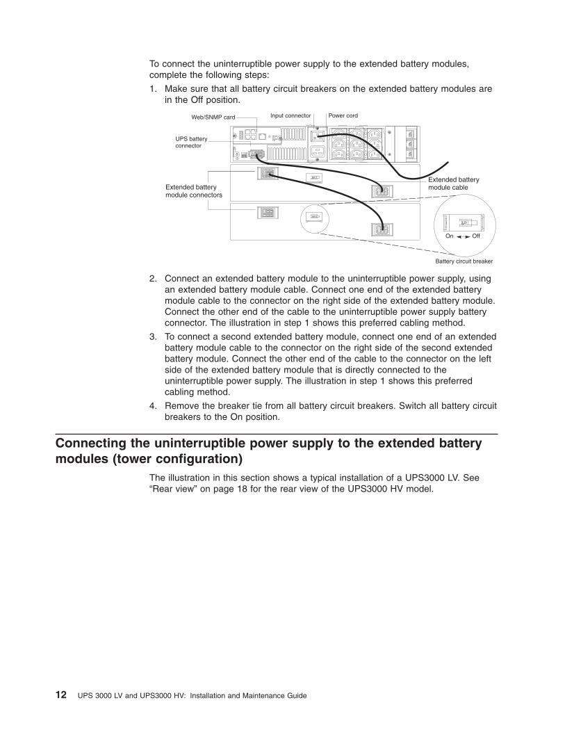
To connect the uninterruptible power supply to the extended battery modules,
complete the following steps:
1. Make sure that all battery circuit breakers on the extended battery modules are
in the Off position.
Battery circuit breaker
UPS batteryconnector
Power cordWeb/SNMP card Input connector
On Off
Extended batterymodule cableExtended battery
module connectors
1 2
Off
On
2. Connect an extended battery module to the uninterruptible power supply, using
an extended battery module cable. Connect one end of the extended battery
module cable to the connector on the right side of the extended battery module.
Connect the other end of the cable to the uninterruptible power supply battery
connector. The illustration in step 1 shows this preferred cabling method.
3. To connect a second extended battery module, connect one end of an extended
battery module cable to the connector on the right side of the second extended
battery module. Connect the other end of the cable to the connector on the left
side of the extended battery module that is directly connected to the
uninterruptible power supply. The illustration in step 1 shows this preferred
cabling method.
4. Remove the breaker tie from all battery circuit breakers. Switch all battery circuit
breakers to the On position.
Connecting the uninterruptible power supply to the extended battery
modules (tower configuration)
The illustration in this section shows a typical installation of a UPS3000 LV. See
“Rear view” on page 18 for the rear view of the UPS3000 HV model.
12 UPS 3000 LV and UPS3000 HV: Installation and Maintenance Guide
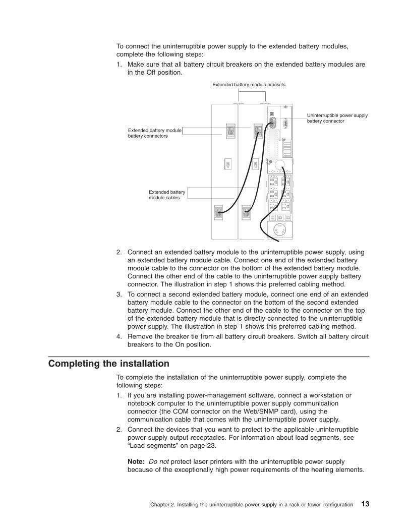
To connect the uninterruptible power supply to the extended battery modules,
complete the following steps:
1. Make sure that all battery circuit breakers on the extended battery modules are
in the Off position.
Extended batterymodule cables
Extended battery modulebattery connectors
Uninterruptible power supplybattery connector
Extended battery module brackets
2. Connect an extended battery module to the uninterruptible power supply, using
an extended battery module cable. Connect one end of the extended battery
module cable to the connector on the bottom of the extended battery module.
Connect the other end of the cable to the uninterruptible power supply battery
connector. The illustration in step 1 shows this preferred cabling method.
3. To connect a second extended battery module, connect one end of an extended
battery module cable to the connector on the bottom of the second extended
battery module. Connect the other end of the cable to the connector on the top
of the extended battery module that is directly connected to the uninterruptible
power supply. The illustration in step 1 shows this preferred cabling method.
4. Remove the breaker tie from all battery circuit breakers. Switch all battery circuit
breakers to the On position.
Completing the installation
To complete the installation of the uninterruptible power supply, complete the
following steps:
1. If you are installing power-management software, connect a workstation or
notebook computer to the uninterruptible power supply communication
connector (the COM connector on the Web/SNMP card), using the
communication cable that comes with the uninterruptible power supply.
2. Connect the devices that you want to protect to the applicable uninterruptible
power supply output receptacles. For information about load segments, see
“Load segments” on page 23.
Note: Do not protect laser printers with the uninterruptible power supply
because of the exceptionally high power requirements of the heating elements.
Chapter 2. Installing the uninterruptible power supply in a rack or tower configuration 13

3. If an emergency power-off (disconnect) switch is required by local codes, see
“Remote emergency power-off installation” to install the remote emergency
power-off switch before you turn on the uninterruptible power supply.
4. Connect the uninterruptible power supply power cord to a power source. All
front panel LEDs flash briefly, and then only the power-on LED flashes,
indicating that the uninterruptible power supply is in Standby mode and the
connected devices are offline. If the alarm beeps or an uninterruptible power
supply general alarm LED stays lit, see Table 7 on page 39.
5. Press and hold the on button until you hear the uninterruptible power supply
beep (approximately 1 second). The power-on LED stops flashing, and the load
level LEDs display the percentage of load that is being applied to the
uninterruptible power supply. The uninterruptible power supply is now in Normal
mode and is providing power to the connected devices.
Notes:
1. The batteries charge to 90% capacity in approximately 3 hours. Make sure that
you charge the batteries for 24 hours after installation or long-term storage.
2. If more than two extended battery modules are installed, use an external battery
charger for faster recharge times.
Remote emergency power-off installation
The uninterruptible power supply includes a remote emergency power-off connector
that enables you to turn off power at the uninterruptible power supply output
receptacles from a customer-supplied switch in a remote location.
The remote emergency power-off feature shuts down the connected devices
immediately and does not follow the orderly shutdown procedure that is initiated by
any power-management software.
Any devices that are operating on battery power are also shut down immediately.
When the remote emergency power-off switch is reset, the connected devices will
not return to battery power until the uninterruptible power supply is restarted
manually.
If the off button is pressed after the remote emergency power-off is activated, the
uninterruptible power supply remains in Standby mode when it is restarted until the
on button is pressed.
Notes:
1. The remote emergency power-off function activates when the remote
emergency power-off contacts close.
2. For Europe, the emergency switch requirements are detailed in Harmonized
document HD-384-48 S1, “Electrical Installation of the Buildings, Part 4:
Protection for Safety, Chapter 46: Isolation and Switching.”
To connect a remote emergency power-off switch, complete the following steps:
1. Turn off the uninterruptible power supply and disconnect all external cables and
power cords.
14 UPS 3000 LV and UPS3000 HV: Installation and Maintenance Guide

2. If the remote emergency power-off connector is installed, disconnect it from the
remote emergency power-off connector on the rear of the uninterruptible power
supply.
Remote emergencypower-off port
Remote emergencypower-off connector
Openings
3. Connect isolated, normally open, dry contacts (rated to handle 60 V dc
maximum, 30 V ac RMS maximum, and 20 mA maximum) to the two openings
on the remote emergency power-off connector. Use stranded, non-shielded
wiring, size 18 - 22 AWG (0.75 mm2 - 0 mm2). Tighten the two small screws on
the remote emergency power-off connector to hold the wire in place.
Note: A separate contact must simultaneously cause uninterruptible power
supply input ac power to be removed.
4. Install the remote emergency power-off connector in the remote emergency
power-off port (see the illustration in step 2).
5. Make sure that the externally connected remote emergency power-off switch is
not activated, to enable power to the uninterruptible power supply output
receptacles.
6. Connect the uninterruptible power supply to a power outlet and press the on
button.
7. Activate the external remote emergency power-off switch to test the remote
emergency power-off function.
8. De-activate the external remote emergency power-off switch and restart the
uninterruptible power supply.
Chapter 2. Installing the uninterruptible power supply in a rack or tower configuration 15

16 UPS 3000 LV and UPS3000 HV: Installation and Maintenance Guide

Chapter 3. Uninterruptible power supply controls, LEDs,
operating modes, and power
This chapter describes the controls, light-emitting diodes (LEDs), connectors,
operating modes, and how to turn the uninterruptible power supply on and off.
Front view
The following illustration shows the controls, LEDs, and connectors on the front of
the uninterruptible power supply.
Load level LEDs
On button
Off button
Alarm reset button
General alarm LED
On battery LED
Battery service LED
Site wiring fault LED
Power on LED
For more information about the LEDs, see “Operating modes” on page 18 and
Table 7 on page 39.
General alarm LED: When this LED is red and flashing and the alarm beeps every
5 seconds, the uninterruptible power supply is charging the battery. When this LED
is red and flashing and the alarm beeps continuously, the uninterruptible power
supply internal temperature is too high. When this LED is flashing and there is no
alarm beep, the battery is recharging.
On battery LED: When this LED is lit, the uninterruptible power supply is running
on battery power. When this LED is flashing, the battery capacity is low.
Battery service LED: When this LED is red and flashing, the battery is not
connected correctly or the battery needs to be replaced.
Site wiring fault LED: When this LED is red and flashing, there are problems with
the wiring outside the uninterruptible power supply.
Power-on LED: When this LED is green, the uninterruptible power supply is in
Normal mode. When this LED is red, the uninterruptible power supply is in Bypass
mode. When this LED is flashing, the uninterruptible power supply is in Standby
mode.
Note: If this LED is off, it does not mean that there is no electrical power in the
uninterruptible power supply. The LED might be burned out. To remove all electrical
power from the uninterruptible power supply, you must disconnect the power cord
from the electrical outlet.
On button: Press this button to turn on the uninterruptible power supply.
Off button: Press this button to turn off the uninterruptible power supply.
© Copyright IBM Corp. 2006, 2008 17

Alarm reset button: Press this button to silence the alarm for an existing fault.
Load level LEDs: When these LEDs are lit, they indicate the percentage of
uninterruptible power supply load capacity that is being used by the connected
devices.
Rear view
The following illustration shows the controls and connectors on the rear of the
UPS3000 LV.
L5-30 receptacle
Battery connector
Power cord with L5-30PRemote emergencypower-off port
5-15 receptacles Circuit breakersWeb/SNMP card
1 2
Off
On
The following illustration shows the controls and connectors on the rear of the
UPS3000 HV.
Remote emergencypower-off port
IEC 320-C19 receptacle
Battery connector
16A, IEC 320-C20input connector
IEC 320-C13receptacles
Circuit breakers
Web/SNMP card
1 2
Off
On
Operating modes
The following illustration shows the operating mode LEDs.
On button
Off button
Alarm reset button
Normal mode LED (steady green)Standby mode LED (flashing green)
Bypass mode LED (steady red)
Load level LEDsBattery mode LED
The uninterruptible power supply has the following operating modes:
v Normal
v Battery
v Bypass
v Standby
18 UPS 3000 LV and UPS3000 HV: Installation and Maintenance Guide

v Configuration
Normal mode
When the uninterruptible power supply is in Normal mode, the power-on LED is lit,
and the front panel displays the percentage of uninterruptible power supply load
capacity that is being used by the connected devices. The uninterruptible power
supply monitors and charges the batteries as needed and provides power protection
to the connected devices.
When all of the load level LEDs and the overload LED are lit, power requirements
exceed uninterruptible power supply capacity. For more information, see
“Troubleshooting guide” on page 39.
Battery mode
When the uninterruptible power supply is operating during a power outage, the
alarm beeps once every 5 seconds, and the battery LED is lit. When the utility
power returns, the uninterruptible power supply switches to Normal mode operation
while the battery recharges.
If battery capacity becomes low while the uninterruptible power supply is in Battery
mode, the battery LED starts flashing, and the alarm becomes continuous.
Immediately complete and save your work to prevent data loss.
When utility power is restored after the uninterruptible power supply shuts down, the
uninterruptible power supply automatically restarts. The general alarm LED flashes
until the battery is recharged to an acceptable level.
Bypass mode
If the uninterruptible power supply reaches an overload condition or has an internal
failure, the uninterruptible power supply transfers the connected devices to utility
power. In this case, Battery mode is not available; however, the utility power
continues to be passively filtered by the uninterruptible power supply. The alarm
sounds, and the power-on LED turns red.
The uninterruptible power supply switches to Bypass mode when any of the
following situations occur:
v The uninterruptible power supply has an overtemperature condition.
v The uninterruptible power supply has an overload condition of 103% to 110% for
30 seconds.
v The uninterruptible power supply detects a fault in the battery or uninterruptible
power supply electronics.
Standby mode
When the uninterruptible power supply is turned off and remains connected to a
power outlet, the uninterruptible power supply is in Standby mode. The power-on
Chapter 3. Uninterruptible power supply controls, LEDs, operating modes, and power 19

LED flashes, and the load level LEDs are off, indicating that power is not available
to the connected devices. The battery recharges when necessary.
Note: For 200 - 240 V models, the output receptacles might remain electrically live
(up to 100 - 120 V). Disconnect the power to the uninterruptible power supply to be
sure that power is not available to the output receptacles.
Configuration mode
When the uninterruptible power supply is in Configuration mode, the front panel
LEDs represent the configuration options. Use the control buttons (on button, off
button, and alarm reset button) to modify the uninterruptible power supply
configuration. The following illustration shows the LEDs and Table 2 on page 21
explains the corresponding options.
4
On button
Off button
Alarm reset button
Configuration mode LEDs
Press and hold the on and alarmreset buttons simultaneously to enterConfiguration mode.
1 2Press the on button toscroll to the next option.
3Press the alarm reset buttonto save the setting and exitConfiguration mode.
Press the off button onetime to select the option.
To work with Configuration mode, complete the following steps:
1. Press and hold the on button and the alarm reset button simultaneously for one
beep (approximately 5 seconds). The uninterruptible power supply switches to
Configuration mode. The LEDs flash briefly and then indicate the enabled
options.
2. Press the on button to scroll through the options. Each time you press the
button, the uninterruptible power supply beeps. The LED for the selected option
indicates the current setting; flashing LEDs indicate disabled options (see the
illustration in step 4 and Table 2 on page 21). Scrolling past the last LED returns
to the first configuration option.
If you press the on button and nothing happens, the uninterruptible power
supply is still in Operation mode. Repeat step 1 for only one beep to enter
Configuration mode, and then repeat this step.
3. Press the off button one time to select the Voltage option or to toggle the site
wiring fault alarm on or off.
Note: The uninterruptible power supply exits Configuration mode automatically
after 2 minutes.
4. Press the alarm reset button to confirm the selection and exit Configuration
mode. If you do not press the alarm reset button, the uninterruptible power
supply defaults to the original settings.
20 UPS 3000 LV and UPS3000 HV: Installation and Maintenance Guide

The Configuration mode LEDs and options are described in Table 2. Use the
following LED legend for an explanation of the LEDs.
Red
Flashing
Not lit
Green
LED legend
For the factory default voltages for IBM uninterruptible power supply models, see
Table 3 on page 22.
Table 2. Configuration mode LEDs and options
Configuration
mode LEDs Option LED status Explanation
100/200 - 208 V
nominal input
voltage
Lit Selecting this option changes the
nominal input voltage on low-voltage
models to 100 V and to 200 - 208 V
for high-voltage models.
Flashing 100/200 - 208 V is disabled; one of
the other input voltage options is
selected.
110/220 V
nominal input
voltage
Lit Selecting this option changes the
nominal input voltage on low voltage
models to 110 V and to 220 V for
high-voltage models.
Flashing 110/220 V is disabled; one of the
other input voltage options is
selected.
120/230 V
nominal input
voltage
Lit Selecting this option changes the
nominal input voltage on low-voltage
models to 120 V and to 230 V for
high-voltage models.
Flashing 120/230V is disabled; one of the
other input voltage options is
selected.
127/240 V
nominal input
voltage
Lit Selecting this option changes the
nominal input voltage on low-voltage
models to 127 V and to 240 V for
high-voltage models.
Flashing 127/240 V is disabled; one of the
other input voltage options is
selected.
Site wiring fault
alarm
Lit An alarm sounds when the polarity
of the outlet is reversed or the
ground connection is missing; have
a qualified electrician repair the
outlet wiring.
Flashing An alarm does not sound when the
polarity of the outlet is reversed or
the ground connection is missing.
The site wiring fault alarm is not
available in 100, 200, and 208 V
models.
Chapter 3. Uninterruptible power supply controls, LEDs, operating modes, and power 21

Table 3. Factory default voltages for IBM uninterruptible power supply models
IBM uninterruptible power
supply model Description Factory default voltage
40K9792 IBM 2130-1JX UPS Japan LV 100 V ac
40K9656 IBM 2130-1RX UPS 120 V ac
40K9793 IBM 2130-2JX UPS Japan
HV
200 V ac
40K9657 IBM 2130-2RX UPS 230 V ac
41Y9276 LV Japan UPS Electronics
Module FRU
100 V ac
40K9713 LV UPS Electronics Module
FRU
120 V ac
41Y9275 HV Japan UPS Electronics
Module FRU
200 V ac
40K9712 HV UPS Electronics Module
FRU
230 V ac
Turning on the uninterruptible power supply
After the uninterruptible power supply is connected to a power outlet, it enters
Standby mode.
To turn on the uninterruptible power supply, press and hold the on button until you
hear the uninterruptible power supply beep (for approximately 1 second). The
power-on LED is lit, and the load level LEDs show the percentage of load that is
being applied to the uninterruptible power supply.
Starting the uninterruptible power supply on battery
Note: Before you use this feature, the uninterruptible power supply must have been
powered by utility power at least one time.
To turn on the uninterruptible power supply without using utility power, press and
hold the on button for at least 4 seconds. The uninterruptible power supply supplies
power to the connected devices, and it switches into Battery mode.
Turning off the uninterruptible power supply
To turn off the uninterruptible power supply, complete the following steps:
1. Prepare the connected devices for shutdown.
2. Press and hold the off button until the long beep ceases (approximately 5
seconds). The power-on LED starts flashing, and the uninterruptible power
supply switches to Standby mode (if utility power is available) and removes
power from the connected devices.
3. Disconnect the power cord from the uninterruptible power supply. If you do not
disconnect the uninterruptible power supply from the power source, it remains in
Standby mode.
22 UPS 3000 LV and UPS3000 HV: Installation and Maintenance Guide

Load segments
Load segments are sets of receptacles that can be controlled by
power-management software, providing an orderly shutdown and startup of the
connected devices. For example, during a power outage, you can keep key devices
running while you turn off other devices. This feature enables you to save battery
power. For more information, see your power-management software documentation.
Note: If you are not using power-management software, you cannot control the
individual load segments.
Each uninterruptible power supply has three load segments.
The following illustration shows the three load segments in the UPS3000 LV
uninterruptible power supply.
Load segment 2 Load segment 3
Load segment 1
The following illustration shows the three load segments in the UPS3000 HV
uninterruptible power supply.
Load segment 2
Load segment 3Load segment 1
Chapter 3. Uninterruptible power supply controls, LEDs, operating modes, and power 23

24 UPS 3000 LV and UPS3000 HV: Installation and Maintenance Guide

Chapter 4. Using the Web/SNMP card
This chapter provides detailed instructions for using the ConnectUPS Web/SNMP
Card that is on the top left side on the rear of the uninterruptible power supply.
Introduction
The Web/SNMP card is a network device for the uninterruptible power supply that
provides both SNMP and HTTP compatibility. The Web/SNMP card can be
connected to a twisted-pair Ethernet network (10BASE-T or 100BASE-T), using an
RJ-45 connector.
The Web/SNMP card has an integrated switching hub that enables three additional
network devices to be connected to the network without the requirement of
additional network drops.
With the Web/SNMP card, you can monitor and manage the uninterruptible power
supply in the following ways:
v Using a Web browser such as Microsoft Internet Explorer or Netscape
v Using an Internet-ready cell phone or personal digital assistant (PDA)
v Using SNMP-compatible network-management software (user-supplied)
The Web/SNMP card also supports remote monitoring and shutdown from computer
systems that are protected by uninterruptible power supplies. NetWatch client
software that is used with the card comes on the Powerware Software Suite CD or
is available from http://www.powerware.com. The client software is available for the
following operating systems:
v Microsoft Windows 95, Windows 98, Windows Me, Windows NT, and Windows
XP
v Macintosh OS X
v Novell NetWare
v UNIX
v Linux
These operating systems communicate through TCP/IP with the Web/SNMP card
and automatically shut down the connected devices during extended power
outages.
In addition, the Web/SNMP card has the following features:
v It can be configured from a serial port, Telnet, or HTTP Web browser.
v It can be managed from a HTTP Web browser, Internet-ready cell phone or PDA,
or SNMP management software.
v E-mail notification of changes in the uninterruptible power supply status can be
generated through simple mail transport protocol (SMTP) using e-mail client
software, a personal communication services (PCS) phone, or alphanumeric
pager.
v It supports Powerware (XUPS.MIB) and RFC-1628 Standard UPS
(STDUPSV1.MIB) management information bases.
v It is firmware upgradable from a Microsoft Windows utility, using a network
connection.
© Copyright IBM Corp. 2006, 2008 25

v It has a scheduling function to control uninterruptible power supply shutdowns
and startups.
v It generated history log files (data and events) for recording power problems.
v Uninterruptible power supply status information is available to registered
NetWatch clients for automatic shutdown of Microsoft Windows
95/98/Me/NT/2000/XP, Mac OS X, Novell NetWare, and UNIX (various versions,
including Linux).
v With a special Status@aGlancet page, a color-coded background on your Web
browser provides quick visibility of the uninterruptible power supply status.
v Multiple Web/SNMP cards can be monitored, using free Powerware MultiView
software.
v Two normally open or normally closed contact devices can be monitored through
a connection to the configuration port. To configure this option, see “Set external
contact monitoring” on page 31.
System application
The following illustration shows how you can use the Web/SNMP card in a network
application.
Ethernet
RS-232
UPS
ConnectUPS-X
NMS stationor
Web browser
Power line
MicrosoftWindows95/98/Me
NT/2000/XP
NetWatch Client
Additional network connectionswith ConnectionUPS-X
NetWatch Client NetWatch Client NetWatch Client
UNIX/Linux NetWare Mac OS X
Managementstation orterminal
26 UPS 3000 LV and UPS3000 HV: Installation and Maintenance Guide

Web/SNMP card LEDs and controls
The following illustration shows the LEDs and controls on the Web/SNMP card.
10 Mb network LEDs (yellow)
DIP switch
Reset button
COM connector
1 2
Additional Ethernet Connectors
100 Mb network LEDs (green) Status LED (yellow)
Power LED (green)
Uplink Ethernet connector
Off
OnWeb/SNMP card
The Web/SNMP card LEDs are described in the following table.
Table 4. Web/SNMP card LED descriptions
Status LED 10 Mb or 100 Mb LED Card function description
Flickering On or flickering Normal operation with Ethernet traffic
On On Web/SNMP card error
Off Off Uninterruptible power supply power is low
(no power to the Web/SNMP card)
Flashing
(approximately once
per second)
Flashing (approximately
once per second)
No connection to uninterruptible power
supply (alternate flashing as the
Web/SNMP card restarts)
Configuring the Web/SNMP card locally
Use the procedure in this section to access the Web/SNMP configuration utility
through a serial connector.
Before you begin
To use the configuration utility for the card, you need the following items:
v The DB9-to-RJ-45 cable that comes with the uninterruptible power supply
v A terminal with a serial communication port, or a computer with a terminal
emulation program. Set the serial line to 9600 baud, no parity, 8 data bits, 1 stop
bit, and no flow control.
Chapter 4. Using the Web/SNMP card 27

Connecting the card to a terminal or computer
To connect the card to a terminal or computer and start the configuration utility,
complete the following steps:
1. Connect the serial cable that comes with the uninterruptible power supply to the
COM connector on the Web/SNMP card.
2. Connect the other end of the serial cable into the TTY connector on the terminal
or the COM connector on a computer.
3. Open a terminal emulation program and select the applicable serial connection
(such as COM1).
Set the serial line to 9600 baud, no parity, 8 data bits, 1 stop bit, and no flow
control.
4. Turn on the uninterruptible power supply.
5. After a few seconds, press Enter. The Password screen is displayed. If the
screen is not displayed, press Enter again.
If you still do not see the Password screen, check the following conditions:
v Make sure that the serial line is set to 9600 baud, no parity, 8 data bits, 1
stop bit, and no flow control.
v If the serial line settings are correct, check the cabling to make sure that all
connections are secure.
v Make sure that the terminal program is on the correct communication port for
the serial connection.
v Make sure that the Web/SNMP card has power (one or more LEDs on the
card are lit) and that the uninterruptible power supply is turned on.
6. Type your password (the default password is admin) and press Enter. The main
menu is displayed.
+===================================================================
| [ ConnectUPS Web/SNMP Card Configuration Utility ]
+===================================================================
Enter Password: *****
+===================================================================
| [ ConnectUPS Web/SNMP Card Configuration Utility ]
+===================================================================
1. Web/SNMP Card Settings
2. Reset Configuration to default
3. Restart Web/SNMP Card
4. UPS Pass-Through
0. Exit
Please Enter Your Choice =>_
Configuring the Web/SNMP card
To configure the Web/SNMP card, complete the following steps:
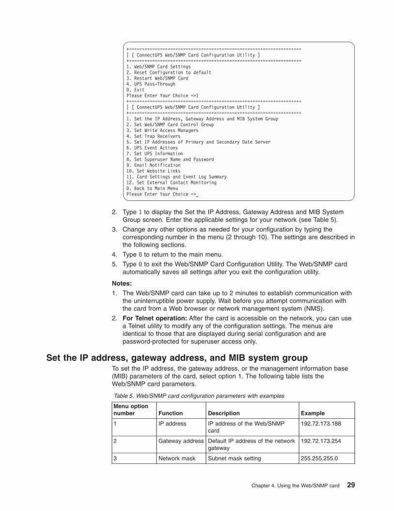
1. In the Web/SNMP Card Configuration Utility main menu, type 1 to display the
settings menu.
28 UPS 3000 LV and UPS3000 HV: Installation and Maintenance Guide
+===================================================================
| [ ConnectUPS Web/SNMP Card Configuration Utility ]
+===================================================================
1. Web/SNMP Card Settings
2. Reset Configuration to default
3. Restart Web/SNMP Card
4. UPS Pass-Through
0. Exit
Please Enter Your Choice =>1
+===================================================================
| [ ConnectUPS Web/SNMP Card Configuration Utility ]
+===================================================================
1. Set the IP Address, Gateway Address and MIB System Group
2. Set Web/SNMP Card Control Group
3. Set Write Access Managers
4. Set Trap Receivers
5. Set IP Addresses of Primary and Secondary Date Server
6. UPS Event Actions
7. Set UPS Information
8. Set Superuser Name and Password
9. Email Notification
10. Set Website Links
11. Card Settings and Event Log Summary
12. Set External Contact Monitoring
0. Back to Main Menu
Please Enter Your Choice =>_
2. Type 1 to display the Set the IP Address, Gateway Address and MIB System
Group screen. Enter the applicable settings for your network (see Table 5).
3. Change any other options as needed for your configuration by typing the
corresponding number in the menu (2 through 10). The settings are described in
the following sections.
4. Type 0 to return to the main menu.
5. Type 0 to exit the Web/SNMP Card Configuration Utility. The Web/SNMP card
automatically saves all settings after you exit the configuration utility.
Notes:
1. The Web/SNMP card can take up to 2 minutes to establish communication with
the uninterruptible power supply. Wait before you attempt communication with
the card from a Web browser or network management system (NMS).
2. For Telnet operation: After the card is accessible on the network, you can use
a Telnet utility to modify any of the configuration settings. The menus are
identical to those that are displayed during serial configuration and are
password-protected for superuser access only.
Set the IP address, gateway address, and MIB system group
To set the IP address, the gateway address, or the management information base
(MIB) parameters of the card, select option 1. The following table lists the
Web/SNMP card parameters.
Table 5. Web/SNMP card configuration parameters with examples
Menu option
number Function Description Example
1 IP address IP address of the Web/SNMP
card
192.72.173.188
2 Gateway address Default IP address of the network
gateway
192.72.173.254
3 Network mask Subnet mask setting 255.255.255.0
Chapter 4. Using the Web/SNMP card 29

Table 5. Web/SNMP card configuration parameters with examples (continued)
Menu option
number Function Description Example
4 sysContact System contact string of MIB (up
to 127 characters)
Powerware
5 sysName System name parameter for MIB
(up to 127 characters
Web/SNMP card
6 sysLocation System location parameter for
MIB (up to 127 characters)
TEST LAB
Set Web/SNMP card control group
To use BOOTP/DHCP, Telnet, or secure HTTP to configure, control, update, or
manage the Web/SNMP card, you must enable or disable certain control
parameters. Select option 2 to modify the parameters.
Notes:
1. To prevent unauthorized viewing of the Web pages that are displayed by the
Web/SNMP card, use option 2 to enable HTTP Security Control.
2. To obtain an IP address by using BOOTP/DHCP (instead of serial
configuration), set DIP switch 2 on the front panel of the Web/SNMP card to the
On position (Off is the default).
Set write access managers
To use an SNMP-compatible NMS to manage the Web/SNMP card, you must add
the IP address of the management station to the list on the Web/SNMP card to
receive read (get) or write (set) access rights. Select option 3 to add or delete the
IP address of the management station. Community strings might be different for
read or write access.
Set trap receivers
To use an SNMP-compatible NMS to manage the Web/SNMP card, you must add
the IP address of the workstation that is intended to be the trap receiver to the list
on the Web/SNMP card. Select option 3 to add or delete the IP address of the trap
receivers. You can modify this information through the HTTP interface after the card
is connected to the network.
Set IP addresses of primary and secondary date server
Computer systems with the Web/SNMP card-compatible NetWatch client software
are periodically monitored by the Web/SNMP card to maintain a consistent date and
time with your network. The IP address of the computer must be listed as the
primary or secondary date server. To set the IP addresses of the primary and
secondary date servers, select option 5. You can modify this information through the
HTTP interface after the card is connected to the network.
UPS event actions
To configure actions that the Web/SNMP card performs during an ac power failure
and low battery events, select option 6. You can modify this information through the
HTTP interface after the card is connected to the network.
30 UPS 3000 LV and UPS3000 HV: Installation and Maintenance Guide

Set UPS information
To enter additional information about the uninterruptible power supply including the
date of the installation and the date of the last battery replacement, select option 7.
You can also set timing values that are relating to the shutdown and restart of the
uninterruptible power supply. You can modify this information through the HTTP
interface after the card is connected to the network.
Set superuser name and password
To set or change the user name and password of the administrator who will use a
Web browser to configure the Web/SNMP card, select option 8.
Email notification
To notify selected e-mail accounts of events and changes in the status as they
occur in the uninterruptible power supply, or to provide a daily status message at a
predetermined time, select option 9. You can modify this information through the
HTTP interface after the card is connected to the network.
Set Web site links
To set links to different Web sites, select option 10. Links are displayed on the
HTTP interface of the Web/SNMP card. You can modify this information through the
HTTP interface after the card is connected to the network.
Card settings and event log summary
To display each configuration menu and the current settings, select option 11. The
current data and event logs for the card are also displayed. You can access this
data through a terminal program, using the DB9-to-RJ-45 cable or through a Telnet
connect. Displaying and capturing the configuration items and log entries is helpful
in service-related situations.
Set external contact monitoring
With the Web/SNMP card (firmware v3.00), two separate contact closures are
supported. Examples of contact devices include rack-door switches, water
detectors, and fire detectors. Select option 12 to configure this feature.
+===================================================================
| [ ConnectUPS Web/SNMP Card Configuration Utility ]
+===================================================================
1. External Contact #1 Name: External Contact #1 Status
2. External Contact #1 Type: Disabled
3. External Contact #2 Name: External Contact #2 Status
4. External Contact #2 Type: Normally Closed
0. Return to previous menu
Please Enter Your Choice =>_
By changing the external contact name (which maps to PowerMIB
xupsContactDescr), you can define the label text of the Contact Status field as
displayed on the Summary page. The defaults are External Contact #1 Status and
External Contact #2 Status. The external contact types have three possible
values:
v Disabled (Default): maps to PowerMIB xupsContactType = notUsed(4)
v Normally Open: maps to PowerMIB xupsContactType = normallyOpen(1)
v Normally Closed: maps to PowerMIB xupsContactType = normallyClosed(2)
Chapter 4. Using the Web/SNMP card 31
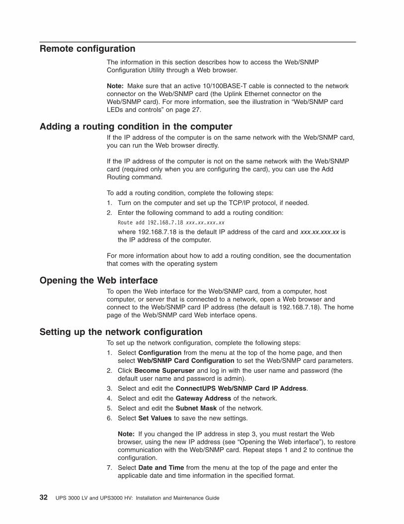
Remote configuration
The information in this section describes how to access the Web/SNMP
Configuration Utility through a Web browser.
Note: Make sure that an active 10/100BASE-T cable is connected to the network
connector on the Web/SNMP card (the Uplink Ethernet connector on the
Web/SNMP card). For more information, see the illustration in “Web/SNMP card
LEDs and controls” on page 27.
Adding a routing condition in the computer
If the IP address of the computer is on the same network with the Web/SNMP card,
you can run the Web browser directly.
If the IP address of the computer is not on the same network with the Web/SNMP
card (required only when you are configuring the card), you can use the Add
Routing command.
To add a routing condition, complete the following steps:
1. Turn on the computer and set up the TCP/IP protocol, if needed.
2. Enter the following command to add a routing condition:
Route add 192.168.7.18 xxx.xx.xxx.xx
where 192.168.7.18 is the default IP address of the card and xxx.xx.xxx.xx is
the IP address of the computer.
For more information about how to add a routing condition, see the documentation
that comes with the operating system
Opening the Web interface
To open the Web interface for the Web/SNMP card, from a computer, host
computer, or server that is connected to a network, open a Web browser and
connect to the Web/SNMP card IP address (the default is 192.168.7.18). The home
page of the Web/SNMP card Web interface opens.
Setting up the network configuration
To set up the network configuration, complete the following steps:
1. Select Configuration from the menu at the top of the home page, and then
select Web/SNMP Card Configuration to set the Web/SNMP card parameters.
2. Click Become Superuser and log in with the user name and password (the
default user name and password is admin).
3. Select and edit the ConnectUPS Web/SNMP Card IP Address.
4. Select and edit the Gateway Address of the network.
5. Select and edit the Subnet Mask of the network.
6. Select Set Values to save the new settings.
Note: If you changed the IP address in step 3, you must restart the Web
browser, using the new IP address (see “Opening the Web interface”), to restore
communication with the Web/SNMP card. Repeat steps 1 and 2 to continue the
configuration.
7. Select Date and Time from the menu at the top of the page and enter the
applicable date and time information in the specified format.
32 UPS 3000 LV and UPS3000 HV: Installation and Maintenance Guide

8. Select Set Values to save the date and time settings.
The Web/SNMP card is now configured for operation on your network. See the
online help for detailed information about each menu selection.
Using the Web/SNMP card in Serial Pass-through mode
During normal operation, the Web/SNMP card controls the communication path to
the uninterruptible power supply and provides network-based access to
uninterruptible power supply data through the Web and through SNMP. You can
disable the normal operation of the Web/SNMP card and enable serial
communication in a pass-through mode directly to the uninterruptible power supply.
You can use Serial Pass-through mode in the following scenarios:
v The uninterruptible power supply firmware requires a field upgrade and a 9600
baud serial port connection to the uninterruptible power supply is required to
perform the upgrade.
v You want to run a local copy of the Powerware LanSafe software and
communicate serially with the uninterruptible power supply.
Before you begin, go to http://www.powerware.com/ to download a later version of
the Web/SNMP card firmware, if it is available.
To set up the Serial Pass-through mode, complete the following steps:
1. Change the DIP switch positions on the Web/SNMP card to On and On. The
default is Off and Off. For the location of the DIP switches, see the illustration
on page 27.
2. Press the Web/SNMP card reset switch to restart the card in the Serial
Pass-through mode.
3. Using the DB9-to-RJ-45 cable that comes with the uninterruptible power supply,
connect the RJ-45 end of the cable into the COM connector on the Web/SNMP
card.
4. Connect the DB9 end of the cable into an available serial port on a workstation
or notebook computer. You can now run applicable software on your workstation
or notebook computer and can communicate serially with the uninterruptible
power supply at 9600 baud, 8 bits, no parity, and 1 stop bit.
Note: In Serial Pass-through mode, communication through the Web/SNMP
Ethernet connector stops, and any existing connections, for example, to
NetWatch software clients or SNMP management tools, also stop.
When you are finished using the Web/SNMP card in Serial Pass-through mode,
disconnect the DB9-to-RJ-45 cable from the card and the workstation or notebook
computer. Return the DIP switches to the original settings, and press the reset
button to restart the card.
Chapter 4. Using the Web/SNMP card 33

34 UPS 3000 LV and UPS3000 HV: Installation and Maintenance Guide
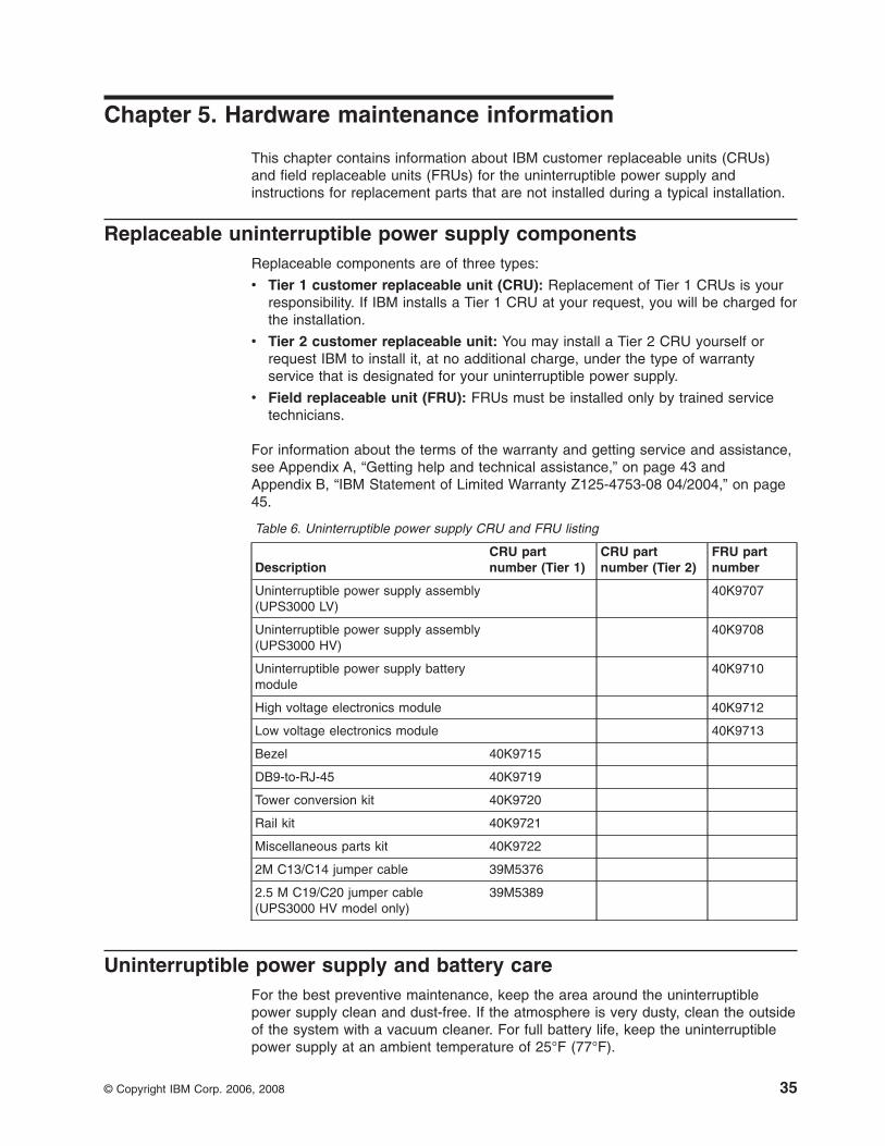
Chapter 5. Hardware maintenance information
This chapter contains information about IBM customer replaceable units (CRUs)
and field replaceable units (FRUs) for the uninterruptible power supply and
instructions for replacement parts that are not installed during a typical installation.
Replaceable uninterruptible power supply components
Replaceable components are of three types:
v Tier 1 customer replaceable unit (CRU): Replacement of Tier 1 CRUs is your
responsibility. If IBM installs a Tier 1 CRU at your request, you will be charged for
the installation.
v Tier 2 customer replaceable unit: You may install a Tier 2 CRU yourself or
request IBM to install it, at no additional charge, under the type of warranty
service that is designated for your uninterruptible power supply.
v Field replaceable unit (FRU): FRUs must be installed only by trained service
technicians.
For information about the terms of the warranty and getting service and assistance,
see Appendix A, “Getting help and technical assistance,” on page 43 and
Appendix B, “IBM Statement of Limited Warranty Z125-4753-08 04/2004,” on page
45.
Table 6. Uninterruptible power supply CRU and FRU listing
Description
CRU part
number (Tier 1)
CRU part
number (Tier 2)
FRU part
number
Uninterruptible power supply assembly
(UPS3000 LV)
40K9707
Uninterruptible power supply assembly
(UPS3000 HV)
40K9708
Uninterruptible power supply battery
module
40K9710
High voltage electronics module 40K9712
Low voltage electronics module 40K9713
Bezel 40K9715
DB9-to-RJ-45 40K9719
Tower conversion kit 40K9720
Rail kit 40K9721
Miscellaneous parts kit 40K9722
2M C13/C14 jumper cable 39M5376
2.5 M C19/C20 jumper cable
(UPS3000 HV model only)
39M5389
Uninterruptible power supply and battery care
For the best preventive maintenance, keep the area around the uninterruptible
power supply clean and dust-free. If the atmosphere is very dusty, clean the outside
of the system with a vacuum cleaner. For full battery life, keep the uninterruptible
power supply at an ambient temperature of 25°F (77°F).
© Copyright IBM Corp. 2006, 2008 35

Storing the uninterruptible power supply and batteries
If you store the uninterruptible power supply for a long period, recharge the battery
every 6 months by connecting the uninterruptible power supply to a power outlet.
The batteries charge to 90% capacity in approximately 3 hours. However, you
should charge the batteries for 24 hours after long-term storage. Check the battery
recharge date on the shipping carton label. If the expiration date has passed and
the batteries were never recharged, do not use the uninterruptible power supply.
Contact your technical-support representative.
Replacing the electronics module (for trained service technician only)
The electronics module can be hot-swapped for replacement without losing power
to the connected devices. The uninterruptible power supply automatically switches
to Bypass mode. Battery mode is not available; however, the utility power continues
to be passively filtered by the uninterruptible power supply.
To replace the electronics module, complete the following steps:
1. Disconnect the extended battery module cable, the remote emergency power-off
cable, and the DB9-to-RJ-45 cable, if they are installed.
2. If the uninterruptible power supply is installed in a rack, remove the
uninterruptible power supply from the rack and set it on a level surface.
3. To remove the uninterruptible power supply bezel, grasp the left and right sides
of the bezel and pull it off.
4. Remove the two screws on the left of the electronics module. Firmly grasp the
module and pull it out of the bay.
Note: To prevent power loss to the connected devices, follow step 5 closely.
5. While you insert the new electronics module, press and hold the alarm reset
button for approximately 5 seconds or until the front panel LEDs are lit
individually.
Note: If the five load level LEDs are flashing, the electronics module might not
be seated correctly. Remove and reinsert the module as described in this step.
36 UPS 3000 LV and UPS3000 HV: Installation and Maintenance Guide

6. Secure the electronics module to the uninterruptible power supply chassis with
the screws that you removed in step 4 on page 36.
7. Replace the front bezel.
8. Reconnect any cables that you removed in step 1 on page 36.
Replacing the battery module (for trained service technicians only)
CAUTION:
Lead-acid batteries can present a risk of electrical burn from high,
short-circuit current. Avoid battery contact with metal materials; remove
watches, rings, or other metal objects, and use tools with insulated handles.
To avoid possible explosion, do not burn.
Exchange only with the IBM-approved part. Recycle or discard the battery as
instructed by local regulations. In the United States, IBM has a process for
the collection of this battery. For information, call 1-800-426-4333. Have the
IBM part number for the battery unit available when you call. (C004)
If the battery service LED is flashing and the audible alarm is beeping once every 5
seconds, you might have to replace the battery module. Contact your
technical-support representative to order new batteries.
Important: Do not disconnect the batteries while the uninterruptible power supply
is in Battery mode. Consider all warnings, cautions, and notes before you replace
batteries.
With the hot-swappable battery feature, you can replace uninterruptible power
supply batteries without turning off the uninterruptible power supply or disconnecting
the load. To remove input power to change the battery, complete the following
steps:
1. Press and hold the off button until the long beep ceases (approximately 5
seconds), and then disconnect the uninterruptible power supply.
2. Wait 60 seconds while the internal processor shuts down before you disconnect
the battery.
To replace the battery module, complete the following steps. You will need a
5/16-inch wrench to remove the battery module.
1. If the uninterruptible power supply is installed in a rack, remove the
uninterruptible power supply from the rack and set it on a level surface.
2. To remove the uninterruptible power supply bezel, grasp the left and right sides
of the bezel and pull it off
Chapter 5. Hardware maintenance information 37

3. Unscrew three nuts (one in the upper-left corner and two on the bottom of the
bracket) and set aside the battery retaining bracket.
4. Pull the battery out onto a flat, stable surface. For information about recycling
the battery, see “Battery return program” on page 66.
5. Slide the new battery module into the uninterruptible power supply.
6. Reinstall the battery retaining bracket and nuts that you removed in step 3.
7. Replace the bezel.
38 UPS 3000 LV and UPS3000 HV: Installation and Maintenance Guide

Chapter 6. Troubleshooting
This chapter provides basic troubleshooting information to help you solve some
common problems that might occur while you are using the uninterruptible power
supply.
Audible alarms and uninterruptible power supply conditions
The uninterruptible power supply has an audible alarm feature to alert you of
potential power problems. Use Table 7 to determine and solve the uninterruptible
power supply alarms and conditions.
Load level LEDs
On button
Off button
Alarm reset button
General alarm LED
On battery LED
Battery service LED
Site wiring fault LED
Power on LED
To silence the alarm for an existing fault, press the alarm reset button. If the
uninterruptible power supply status changes, the alarm beeps, overriding the
previous alarm silencing. The alarm cannot be silenced if there is a low-battery
condition.
Troubleshooting guide
The uninterruptible power supply alarms, conditions, causes, and actions are
described in Table 7. Use the following LED legend for an explanation of the LEDs.
Red
Flashing
Not lit
Green
LED legend
Table 7. Troubleshooting guide
Alarm or condition Possible cause Action
ThepPower-on LED is not lit;
the uninterruptible power supply
does not start.
The power cord is not
connected correctly.
Check the power cord connections
The electrical outlet is faulty. Have a qualified electrician test and repair the outlet.
The power-on LED is flashing;
power is not available at the
uninterruptible power supply
output receptacles.
The uninterruptible power
supply is in Standby mode.
Press the on button to supply power to the connected
devices.
The uninterruptible power
supply does not provide the
expected backup time.
The batteries must be
charged or serviced.
Connect the uninterruptible power supply into an
electrical outlet for 24 hours to charge the battery. If
the Battery service LED is lit, see “Replacing
Batteries” on page 44 to replace the battery.
© Copyright IBM Corp. 2006, 2008 39

Table 7. Troubleshooting guide (continued)
Alarm or condition Possible cause Action
1 beep every 5 seconds.
The uninterruptible power
supply is running on battery
power because of a utility
failure.
The uninterruptible power supply is powering the
equipment with battery power. Prepare the connected
devices for shutdown.
The uninterruptible power
supply is running on battery
power because the input
voltage is too high or too
low.
The uninterruptible power supply continues to operate
on battery until the condition is corrected or the
battery is completely discharged.
If the condition remains, the input voltage in your
area might differ from the uninterruptible power
supply nominal. Change the uninterruptible power
supply input voltage to match your local voltage; see
“Configuration mode” on page 20.
The utility line voltage and
frequency are out of
specification.
Have a qualified electrician check the wiring.
Continuous audible alarm.
The battery is running low. Three minutes or less of battery power remains
(depending on load configuration and battery charge).
Save your work and turn off the connected devices.
The alarm cannot be silenced.
1 beep every 5 seconds.
The battery is not connected
correctly.
Check the battery connections. Call your service
representative if the problem persists.
The battery must be
replaced (trained service
technician only).
Contact your technical-support representative to order
a new battery. Have the battery replaced by a trained
service technician only.
1 beep every 5 seconds.
The battery is low when the
uninterruptible power supply
starts up or resumes
operation after a utility
failure.
The uninterruptible power supply is recharging the
battery. The LED is not lit when the battery has
reached an acceptable charge level. If the alarm
reset LED or battery service LED is still lit after 24
hours, contact your technical-support representative.
1 beep every 5 seconds.
A ground wire connection
does not exist, or the line
and neutral wires are
reversed in the electrical
outlet.
Have a qualified electrician correct the wiring. To
disable this alarm, see “Configuration mode” on page
20.
1 beep every 5 seconds.
Bypass is out of tolerance.
Input voltage is not within
±12% of nominal.
The uninterruptible power supply is receiving utility
power that might be unstable or in a brownout
condition. The uninterruptible power supply continues
to supply power to the connected devices. If the
conditions worsen, the uninterruptible power supply
might switch to battery power.
The uninterruptible power
supply is in Bypass mode.
The connected devices are transferred to utility
power. Battery mode is not available; however, the
utility power continues to be passively filtered by the
uninterruptible power supply. Check for one of the
following alarms: overtemperature, overload,
uninterruptible power supply failure, or battery
service.
40 UPS 3000 LV and UPS3000 HV: Installation and Maintenance Guide

Table 7. Troubleshooting guide (continued)
Alarm or condition Possible cause Action
Power requirements exceed
uninterruptible power supply
capacity (103 - 110% for 30
seconds) or the load is
defective.
Turn off and disconnect the uninterruptible power
supply. Remove some of the connected devices from
the uninterruptible power supply. Wait at least 5
seconds until all LEDs are off and restart the
uninterruptible power supply. You might have to
obtain a larger capacity uninterruptible power supply.
Continuous audible alarm.
Uninterruptible power supply
internal temperature is too
high.
The uninterruptible power supply switches to Bypass
mode, allowing the uninterruptible power supply to
cool. Turn off and disconnect the uninterruptible
power supply. Clear vents and remove any heat
sources. Make sure that the airflow around the
uninterruptible power supply is not restricted. Wait at
least 5 minutes and restart the uninterruptible power
supply. If the condition remains, contact your
technical-support representative.
Momentary overload The uninterruptible power supply switches to Bypass
mode. Repeat overloads will lock on bypass for one
hour; press the on button to override Bypass mode
immediately.
Uninterruptible power supply
fault condition
Save your work and turn off the connected devices.
Turn off and disconnect the uninterruptible power
supply. Contact your technical-support representative.
The alarm cannot be silenced.
Chapter 6. Troubleshooting 41

42 UPS 3000 LV and UPS3000 HV: Installation and Maintenance Guide

Appendix A. Getting help and technical assistance
If you need help, service, or technical assistance or just want more information
about IBM products, you will find a wide variety of sources available from IBM to
assist you. This section contains information about where to go for additional
information about IBM and IBM products, what to do if you experience a problem
with your system, and whom to call for service, if it is necessary.
Before you call
Before you call, make sure that you have taken these steps to try to solve the
problem yourself:
v Check all cables to make sure that they are connected.
v Check the power switches to make sure that the system and any optional
devices are turned on.
v Use the troubleshooting information in your system documentation, and use the
diagnostic tools that come with your system. Information about diagnostic tools is
in the Problem Determination and Service Guide on the IBM Documentation CD
that comes with your system.
v Go to the IBM support Web site at http://www.ibm.com/systems/support/ to check
for technical information, hints, tips, and new device drivers or to submit a
request for information.
You can solve many problems without outside assistance by following the
troubleshooting procedures that IBM provides in the online help or in the
documentation that is provided with your IBM product. The documentation that
comes with IBM systems also describes the diagnostic tests that you can perform.
Most systems, operating systems, and programs come with documentation that
contains troubleshooting procedures and explanations of error messages and error
codes. If you suspect a software problem, see the documentation for the operating
system or program.
Using the documentation
Information about your IBM system and preinstalled software, if any, or optional
device is available in the documentation that comes with the product. That
documentation can include printed documents, online documents, readme files, and
help files. See the troubleshooting information in your system documentation for
instructions for using the diagnostic programs. The troubleshooting information or
the diagnostic programs might tell you that you need additional or updated device
drivers or other software. IBM maintains pages on the World Wide Web where you
can get the latest technical information and download device drivers and updates.
To access these pages, go to http://www.ibm.com/systems/support/ and follow the
instructions. Also, some documents are available through the IBM Publications
Center at http://www.ibm.com/shop/publications/order/.
Getting help and information from the World Wide Web
On the World Wide Web, the IBM Web site has up-to-date information about IBM
systems, optional devices, services, and support. The address for IBM System x™
and xSeries® information is http://www.ibm.com/systems/x/. The address for IBM
BladeCenter® information is http://www.ibm.com/systems/bladecenter/. The address
for IBM IntelliStation® information is http://www.ibm.com/intellistation/.
© Copyright IBM Corp. 2006, 2008 43
You can find service information for IBM systems and optional devices at
http://www.ibm.com/systems/support/.
Software service and support
Through IBM Support Line, you can get telephone assistance, for a fee, with usage,
configuration, and software problems with System x and xSeries servers,
BladeCenter products, IntelliStation workstations, and appliances. For information
about which products are supported by Support Line in your country or region, see
http://www.ibm.com/services/sl/products/.
For more information about Support Line and other IBM services, see
http://www.ibm.com/services/, or see http://www.ibm.com/planetwide/ for support
telephone numbers. In the U.S. and Canada, call 1-800-IBM-SERV
(1-800-426-7378).
Hardware service and support
You can receive hardware service through your IBM reseller or IBM Services. To
locate a reseller authorized by IBM to provide warranty service, go to
http://www.ibm.com/partnerworld/ and click Find a Business Partner on the right
side of the page. For IBM support telephone numbers, see http://www.ibm.com/planetwide/. In the U.S. and Canada, call 1-800-IBM-SERV (1-800-426-7378).
In the U.S. and Canada, hardware service and support is available 24 hours a day,
7 days a week. In the U.K., these services are available Monday through Friday,
from 9 a.m. to 6 p.m.
IBM Taiwan product service
IBM Taiwan product service contact information:
IBM Taiwan Corporation
3F, No 7, Song Ren Rd.
Taipei, Taiwan
Telephone: 0800-016-888
44 UPS 3000 LV and UPS3000 HV: Installation and Maintenance Guide

Appendix B. IBM Statement of Limited Warranty Z125-4753-08
04/2004
Part 1 - General Terms
Part 1 - General Terms
This Statement of Limited Warranty includes Part 1 - General Terms, Part 2 -
Country-unique Terms, and Part 3 - Warranty Information. The terms of Part 2
replace or modify those of Part 1. The warranties provided by IBM in this Statement
of Limited Warranty apply only to Machines you purchase for your use, and not for
resale. The term “Machine” means an IBM machine, its features, conversions,
upgrades, elements, or accessories, or any combination of them. The term
“Machine” does not include any software programs, whether pre-loaded with the
Machine, installed subsequently or otherwise. Nothing in this Statement of
Limited Warranty affects any statutory rights of consumers that cannot be
waived or limited by contract.
What this Warranty Covers
IBM warrants that each Machine 1) is free from defects in materials and
workmanship and 2) conforms to IBM’s Official Published Specifications
(“Specifications”) which are available on request. The warranty period for the
Machine starts on the original Date of Installation and is specified in Part 3 -
Warranty Information. The date on your invoice or sales receipt is the Date of
Installation unless IBM or your reseller informs you otherwise. Many features,
conversions, or upgrades involve the removal of parts and their return to IBM. A
part that replaces a removed part will assume the warranty service status of the
removed part. Unless IBM specifies otherwise, these warranties apply only in the
country or region in which you purchased the Machine.
THESE WARRANTIES ARE YOUR EXCLUSIVE WARRANTIES AND REPLACE
ALL OTHER WARRANTIES OR CONDITIONS, EXPRESS OR IMPLIED,
INCLUDING, BUT NOT LIMITED TO, THE IMPLIED WARRANTIES OR
CONDITIONS OF MERCHANTABILITY AND FITNESS FOR A PARTICULAR
PURPOSE. SOME STATES OR JURISDICTIONS DO NOT ALLOW THE
EXCLUSION OF EXPRESS OR IMPLIED WARRANTIES, SO THE ABOVE
EXCLUSION MAY NOT APPLY TO YOU. IN THAT EVENT, SUCH WARRANTIES
ARE LIMITED IN DURATION TO THE WARRANTY PERIOD. NO WARRANTIES
APPLY AFTER THAT PERIOD. SOME STATES OR JURISDICTIONS DO NOT
ALLOW LIMITATIONS ON HOW LONG AN IMPLIED WARRANTY LASTS, SO
THE ABOVE LIMITATION MAY NOT APPLY TO YOU.
What this Warranty Does not Cover
This warranty does not cover the following:
v any software programs, whether pre-loaded or shipped with the Machine, or
installed subsequently;
v failure resulting from misuse (including but not limited to use of any Machine
capacity or capability, other than that authorized by IBM in writing), accident,
modification, unsuitable physical or operating environment, or improper
maintenance by you;
v failure caused by a product for which IBM is not responsible; and
v any non-IBM products, including those that IBM may procure and provide with or
integrate into an IBM Machine at your request.
© Copyright IBM Corp. 2006, 2008 45

The warranty is voided by removal or alteration of identification labels on the
Machine or its parts.
IBM does not warrant uninterrupted or error-free operation of a Machine.
Any technical or other support provided for a Machine under warranty, such as
assistance with “how-to” questions and those regarding Machine set-up and
installation, is provided WITHOUT WARRANTIES OF ANY KIND.
How to Obtain Warranty Service
If the Machine does not function as warranted during the warranty period, contact
IBM or your reseller to obtain warranty service. If you do not register the Machine
with IBM, you may be required to present proof of purchase as evidence of your
entitlement to warranty service.
What IBM Will Do to Correct Problems
When you contact IBM for service, you must follow the problem determination and
resolution procedures that IBM specifies. An initial diagnosis of your problem can be
made either by a technician over the telephone or electronically by access to an
IBM website.
The type of warranty service applicable to your Machine is specified in Part 3 -
Warranty Information.
You are responsible for downloading and installing designated Machine Code
(microcode, basic input/output system code (called “BIOS”), utility programs, device
drivers, and diagnostics delivered with an IBM Machine) and other software updates
from an IBM Internet Web site or from other electronic media, and following the
instructions that IBM provides.
If your problem can be resolved with a Customer Replaceable Unit (“CRU”) (e.g.,
keyboard, mouse, speaker, memory, hard disk drive), IBM will ship the CRU to you
for you to install.
If the Machine does not function as warranted during the warranty period and your
problem cannot be resolved over the telephone or electronically, through your
application of Machine Code or software updates, or with a CRU, IBM or your
reseller, if approved by IBM to provide warranty service, will either, at its discretion,
1) repair it to make it function as warranted, or 2) replace it with one that is at least
functionally equivalent. If IBM is unable to do either, you may return the Machine to
your place of purchase and your money will be refunded.
IBM or your reseller will also manage and install selected engineering changes that
apply to the Machine.
Exchange of a Machine or Part
When the warranty service involves the exchange of a Machine or part, the item
IBM or your reseller replaces becomes its property and the replacement becomes
yours. You represent that all removed items are genuine and unaltered. The
replacement may not be new, but will be in good working order and at least
functionally equivalent to the item replaced. The replacement assumes the warranty
service status of the replaced item.
46 UPS 3000 LV and UPS3000 HV: Installation and Maintenance Guide

Your Additional Responsibilities
Before IBM or your reseller exchanges a Machine or part, you agree to remove all
features, parts, options, alterations, and attachments not under warranty service.
You also agree to:
1. ensure that the Machine is free of any legal obligations or restrictions that
prevent its exchange;
2. obtain authorization from the owner to have IBM or your reseller service a
Machine that you do not own; and
3. where applicable, before service is provided:
a. follow the service request procedures that IBM or your reseller provides;
b. backup or secure all programs, data, and funds contained in the Machine;
c. provide IBM or your reseller with sufficient, free, and safe access to your
facilities to permit IBM to fulfill its obligations; and
d. inform IBM or your reseller of changes in the Machine’s location.4. (a) ensure all information about identified or identifiable individuals (Personal
Data) is deleted from the Machine (to the extent technically possible), (b) allow
IBM, your reseller or an IBM supplier to process on your behalf any remaining
Personal Data as IBM or your reseller considers necessary to fulfill its
obligations under this Statement of Limited Warranty (which may include
shipping the Machine for such processing to other IBM service locations around
the world), and (c) ensure that such processing complies with any laws
applicable to such Personal Data.
Limitation of Liability
IBM is responsible for loss of, or damage to, your Machine only while it is 1) in
IBM’s possession or 2) in transit in those cases where IBM is responsible for the
transportation charges.
Neither IBM nor your reseller are responsible for any of your confidential,
proprietary or personal information contained in a Machine which you return to IBM
for any reason. You should remove all such information from the Machine prior to its
return.
Circumstances may arise where, because of a default on IBM’s part or other
liability, you are entitled to recover damages from IBM. In each such instance,
regardless of the basis on which you are entitled to claim damages from IBM
(including fundamental breach, negligence, misrepresentation, or other contract or
tort claim), except for any liability that cannot be waived or limited by applicable
laws, IBM is liable for no more than
1. damages for bodily injury (including death) and damage to real property and
tangible personal property; and
2. the amount of any other actual direct damages, up to the charges (if recurring,
12 months’ charges apply) for the Machine that is subject of the claim. For
purposes of this item, the term “Machine” includes Machine Code and Licensed
Internal Code (“LIC”).
This limit also applies to IBM’s suppliers and your reseller. It is the maximum for
which IBM, its suppliers, and your reseller are collectively responsible.
UNDER NO CIRCUMSTANCES IS IBM, ITS SUPPLIERS OR RESELLERS
LIABLE FOR ANY OF THE FOLLOWING EVEN IF INFORMED OF THEIR
POSSIBILITY: 1) THIRD PARTY CLAIMS AGAINST YOU FOR DAMAGES
(OTHER THAN THOSE UNDER THE FIRST ITEM LISTED ABOVE); 2) LOSS OF,
Appendix B. IBM Statement of Limited Warranty Z125-4753-08 04/2004 47

OR DAMAGE TO, DATA; 3) SPECIAL, INCIDENTAL, OR INDIRECT DAMAGES
OR FOR ANY ECONOMIC CONSEQUENTIAL DAMAGES; OR 4) LOST
PROFITS, BUSINESS REVENUE, GOODWILL OR ANTICIPATED SAVINGS.
SOME STATES OR JURISDICTIONS DO NOT ALLOW THE EXCLUSION OR
LIMITATION OF INCIDENTAL OR CONSEQUENTIAL DAMAGES, SO THE
ABOVE LIMITATION OR EXCLUSION MAY NOT APPLY TO YOU. SOME STATES
OR JURISDICTIONS DO NOT ALLOW LIMITATIONS ON HOW LONG AN
IMPLIED WARRANTY LASTS, SO THE ABOVE LIMITATION MAY NOT APPLY
TO YOU.
Governing Law
Both you and IBM consent to the application of the laws of the country in which you
acquired the Machine to govern, interpret, and enforce all of your and IBM’s rights,
duties, and obligations arising from, or relating in any manner to, the subject matter
of this Statement of Limited Warranty, without regard to conflict of law principles.
THESE WARRANTIES GIVE YOU SPECIFIC LEGAL RIGHTS AND YOU MAY
ALSO HAVE OTHER RIGHTS WHICH VARY FROM STATE TO STATE OR
JURISDICTION TO JURISDICTION.
Jurisdiction
All of our rights, duties, and obligations are subject to the courts of the country in
which you acquired the Machine.
Part 2 - Country-unique Terms
AMERICAS
ARGENTINA
Jurisdiction: The following is added after the first sentence:
Any litigation arising from this Statement of Limited Warranty will be settled
exclusively by the Ordinary Commercial Court of the city of Buenos Aires.
BOLIVIA
Jurisdiction: The following is added after the first sentence:
Any litigation arising from this Statement of Limited Warranty will be settled
exclusively by the courts of the city of La Paz.
BRAZIL
Jurisdiction: The following is added after the first sentence:Any litigation arising from this Statement of Limited Warranty will be settled
exclusively by the court of Rio de Janeiro, RJ.
CHILE
Jurisdiction: The following is added after the first sentence:
Any litigation arising from this Statement of Limited Warranty will be settled
exclusively by the Civil Courts of Justice of Santiago.
48 UPS 3000 LV and UPS3000 HV: Installation and Maintenance Guide

COLOMBIA
Jurisdiction: The following is added after the first sentence:
Any litigation arising from this Statement of Limited Warranty will be settled
exclusively by the Judges of the Republic of Colombia.
EQUADOR
Jurisdiction: The following is added after the first sentence:
Any litigation arising from this Statement of Limited Warranty will be settled
exclusively by the Judges of Quito.
MEXICO
Jurisdiction: The following is added after the first sentence:
Any litigation arising from this Statement of Limited Warranty will be settled
exclusively by the Federal Courts of Mexico City, Federal District.
PARAGUAY
Jurisdiction: The following is added after the first sentence:
Any litigation arising from this Statement of Limited Warranty will be settled
exclusively by the courts of the city of Asuncion.
PERU
Limitation of Liability: The following is added at the end of this section:
In accordance with Article 1328 of the Peruvian Civil Code the limitations and
exclusions specified in this section will not apply to damages caused by IBM’s willful
misconduct (“dolo”) or gross negligence (“culpa inexcusable”).
URUGUAY
Jurisdiction: The following is added after the first sentence:
Any litigation arising from this Statement of Limited Warranty will be settled
exclusively by the City of Montevideo Court’s Jurisdiction.
VENEZUELA
Jurisdiction: The following is added after the first sentence:
Any litigation arising from this Statement of Limited Warranty will be settled
exclusively by the Courts of the Metropolitan Area Of the City of Caracas.
NORTH AMERICA
How to Obtain Warranty Service: The following is added to this Section:
To obtain warranty service from IBM in Canada or the United States, call
1-800-IBM-SERV (426-7378).
Appendix B. IBM Statement of Limited Warranty Z125-4753-08 04/2004 49

CANADA
Limitation of Liability: The following replaces item 1 of this section:
1. damages for bodily injury (including death) or physical harm to real property
and tangible personal property caused by IBM’s negligence; and
Governing Law: The following replaces “laws of the country in which you acquired
the Machine” in the first sentence:
laws in the Province of Ontario.
UNITED STATES
Governing Law: The following replaces “laws of the country in which you acquired
the Machine” in the first sentence:
laws of the State of New York.
ASIA PACIFIC
AUSTRALIA
What this Warranty Covers: The following paragraph is added to this section:
The warranties specified in this Section are in addition to any rights you may have
under the Trade Practices Act 1974 or other similar legislation and are only limited
to the extent permitted by the applicable legislation.
Limitation of Liability: The following is added to this section:
Where IBM is in breach of a condition or warranty implied by the Trade Practices
Act 1974 or other similar legislation, IBM’s liability is limited to the repair or
replacement of the goods or the supply of equivalent goods. Where that condition
or warranty relates to right to sell, quiet possession or clear title, or the goods are of
a kind ordinarily acquired for personal, domestic or household use or consumption,
then none of the limitations in this paragraph apply.
Governing Law: The following replaces “laws of the country in which you acquired
the Machine” in the first sentence:
laws of the State or Territory.
CAMBODIA AND LAOS
Governing Law: The following replaces “laws of the country in which you acquired
the Machine” in the first sentence:laws of the State of New York, United States of America.
CAMBODIA, INDONESIA, AND LAOS
Arbitration: The following is added under this heading:
Disputes arising out of or in connection with this Statement of Limited Warranty
shall be finally settled by arbitration which shall be held in Singapore in accordance
with the Arbitration Rules of Singapore International Arbitration Center (“SIAC
Rules”) then in effect. The arbitration award shall be final and binding for the parties
without appeal and shall be in writing and set forth the findings of fact and the
conclusions of law.
The number of arbitrators shall be three, with each side to the dispute being entitled
to appoint one arbitrator. The two arbitrators appointed by the parties shall appoint
a third arbitrator who shall act as chairman of the proceedings. Vacancies in the
50 UPS 3000 LV and UPS3000 HV: Installation and Maintenance Guide

post of chairman shall be filled by the president of the SIAC. Other vacancies shall
be filled by the respective nominating party. Proceedings shall continue from the
stage they were at when the vacancy occurred.
If one of the parties refuses or otherwise fails to appoint an arbitrator within 30 days
of the date the other party appoints its, the first appointed arbitrator shall be the
sole arbitrator, provided that the arbitrator was validly and properly appointed.
All proceedings shall be conducted, including all documents presented in such
proceedings, in the English language. The English language version of this
Statement of Limited Warranty prevails over any other language version.
HONG KONG S.A.R. OF CHINA AND MACAU S.A.R. OF CHINA
Governing Law: The following replaces “laws of the country in which you acquired
the Machine” in the first sentence:
laws of Hong Kong Special Administrative Region of China.
INDIA
Limitation of Liability: The following replaces items 1 and 2 of this section:
1. liability for bodily injury (including death) or damage to real property and tangible
personal property will be limited to that caused by IBM’s negligence; and
2. as to any other actual damage arising in any situation involving nonperformance
by IBM pursuant to, or in any way related to the subject of this Statement of
Limited Warranty, the charge paid by you for the individual Machine that is the
subject of the claim. For purposes of this item, the term “Machine” includes
Machine Code and Licensed Internal Code (“LIC”).
Arbitration: The following is added under this heading:
Disputes arising out of or in connection with this Statement of Limited Warranty
shall be finally settled by arbitration which shall be held in Bangalore, India in
accordance with the laws of India then in effect. The arbitration award shall be final
and binding for the parties without appeal and shall be in writing and set forth the
findings of fact and the conclusions of law.
The number of arbitrators shall be three, with each side to the dispute being entitled
to appoint one arbitrator. The two arbitrators appointed by the parties shall appoint
a third arbitrator who shall act as chairman of the proceedings. Vacancies in the
post of chairman shall be filled by the president of the Bar Council of India. Other
vacancies shall be filled by the respective nominating party. Proceedings shall
continue from the stage they were at when the vacancy occurred.
If one of the parties refuses or otherwise fails to appoint an arbitrator within 30 days
of the date the other party appoints its, the first appointed arbitrator shall be the
sole arbitrator, provided that the arbitrator was validly and properly appointed.
All proceedings shall be conducted, including all documents presented in such
proceedings, in the English language. The English language version of this
Statement of Limited Warranty prevails over any other language version.
JAPAN
Appendix B. IBM Statement of Limited Warranty Z125-4753-08 04/2004 51

Governing Law: The following sentence is added to this section:Any doubts concerning this Statement of Limited Warranty will be initially resolved
between us in good faith and in accordance with the principle of mutual trust.
MALAYSIA
Limitation of Liability: The word “SPECIAL” in item 3 of the fifth paragraph is
deleted.
NEW ZEALAND
What this Warranty Covers: The following paragraph is added to this section:
The warranties specified in this section are in addition to any rights you may have
under the Consumer Guarantees Act 1993 or other legislation which cannot be
excluded or limited. The Consumer Guarantees Act 1993 will not apply in respect of
any goods which IBM provides, if you require the goods for the purposes of a
business as defined in that Act.
Limitation of Liability: The following is added to this section:Where Machines are not acquired for the purposes of a business as defined in the
Consumer Guarantees Act 1993, the limitations in this section are subject to the
limitations in that Act.
PEOPLE’S REPUBLIC OF CHINA (PRC)
Governing Law: The following replaces “laws of the country in which you acquired
the Machine” in the first sentence:
laws of the State of New York, United States of America (except when local law
requires otherwise).
PHILIPPINES
Limitation of Liability: Item 3 in the fifth paragraph is replaced by the following:
SPECIAL (INCLUDING NOMINAL AND EXEMPLARY DAMAGES), MORAL,
INCIDENTAL, OR INDIRECT DAMAGES FOR ANY ECONOMIC
CONSEQUENTIAL DAMAGES; OR
Arbitration: The following is added under this heading:
Disputes arising out of or in connection with this Statement of Limited Warranty
shall be finally settled by arbitration which shall be held in Metro Manila, Philippines
in accordance with the laws of the Philippines then in effect. The arbitration award
shall be final and binding for the parties without appeal and shall be in writing and
set forth the findings of fact and the conclusions of law.
The number of arbitrators shall be three, with each side to the dispute being entitled
to appoint one arbitrator. The two arbitrators appointed by the parties shall appoint
a third arbitrator who shall act as chairman of the proceedings. Vacancies in the
post of chairman shall be filled by the president of the Philippine Dispute Resolution
Center, Inc. Other vacancies shall be filled by the respective nominating party.
Proceedings shall continue from the stage they were at when the vacancy occurred.
52 UPS 3000 LV and UPS3000 HV: Installation and Maintenance Guide

If one of the parties refuses or otherwise fails to appoint an arbitrator within 30 days
of the date the other party appoints its, the first appointed arbitrator shall be the
sole arbitrator, provided that the arbitrator was validly and properly appointed.
All proceedings shall be conducted, including all documents presented in such
proceedings, in the English language. The English language version of this
Statement of Limited Warranty prevails over any other language version.
SINGAPORE
Limitation of Liability: The words “SPECIAL” and “ECONOMIC” in item 3 in the
fifth paragraph are deleted.
EUROPE, MIDDLE EAST, AFRICA (EMEA)
THE FOLLOWING TERMS APPLY TO ALL EMEA COUNTRIES:
The terms of this Statement of Limited Warranty apply to Machines purchased from
IBM or an IBM reseller.
How to Obtain Warranty Service:
Add the following paragraph in Western Europe (Andorra, Austria, Belgium,
Cyprus, Czech Republic, Denmark, Estonia, Finland, France, Germany, Greece,
Hungary, Iceland, Ireland, Italy, Latvia, Liechtenstein, Lithuania, Luxembourg, Malta,
Monaco, Netherlands, Norway, Poland, Portugal, San Marino, Slovakia, Slovenia,
Spain, Sweden, Switzerland, United Kingdom, Vatican State, and any country
subsequently added to the European Union, as from the date of accession):
The warranty for Machines acquired in Western Europe shall be valid and
applicable in all Western Europe countries provided the Machines have been
announced and made available in such countries.
If you purchase a Machine in one of the Western European countries, as defined
above, you may obtain warranty service for that Machine in any of those countries
from either (1) an IBM reseller approved to perform warranty service or (2) from
IBM, provided the Machine has been announced and made available by IBM in the
country in which you wish to obtain service.
If you purchased a Personal Computer Machine in Albania, Armenia, Belarus,
Bosnia and Herzegovina, Bulgaria, Croatia, Czech Republic, Georgia, Hungary,
Kazakhstan, Kyrgyzstan, Federal Republic of Yugoslavia, Former Yugoslav Republic
of Macedonia (FYROM), Moldova, Poland, Romania, Russia, Slovak Republic,
Slovenia, or Ukraine, you may obtain warranty service for that Machine in any of
those countries from either (1) an IBM reseller approved to perform warranty
service or (2) from IBM.
If you purchase a Machine in a Middle Eastern or African country, you may obtain
warranty service for that Machine from the IBM entity within the country of
purchase, if that IBM entity provides warranty service in that country, or from an
IBM reseller, approved by IBM to perform warranty service on that Machine in that
country. Warranty service in Africa is available within 50 kilometers of an IBM
approved service provider. You are responsible for transportation costs for Machines
located outside 50 kilometers of an IBM approved service provider.
Governing Law:
Appendix B. IBM Statement of Limited Warranty Z125-4753-08 04/2004 53

The phrase “the laws of the country in which you acquired the Machine” is replaced
by:
1) “the laws of Austria” in Albania, Armenia, Azerbaijan, Belarus,
Bosnia-Herzegovina, Bulgaria, Croatia, Georgia, Hungary, Kazakhstan,
Kyrgyzstan, FYR Macedonia, Moldova, Poland, Romania, Russia, Slovakia,
Slovenia, Tajikistan, Turkmenistan, Ukraine, Uzbekistan, and FR Yugoslavia; 2)
“the laws of France” in Algeria, Benin, Burkina Faso, Cameroon, Cape Verde,
Central African Republic, Chad, Comoros, Congo Republic, Djibouti,
Democratic Republic of Congo, Equatorial Guinea, French Guiana, French
Polynesia, Gabon, Gambia, Guinea, Guinea-Bissau, Ivory Coast, Lebanon,
Madagascar, Mali, Mauritania, Mauritius, Mayotte, Morocco, New Caledonia,
Niger, Reunion, Senegal, Seychelles, Togo, Tunisia, Vanuatu, and Wallis &
Futuna; 3) “the laws of Finland” in Estonia, Latvia, and Lithuania; 4) “the laws of
England” in Angola, Bahrain, Botswana, Burundi, Egypt, Eritrea, Ethiopia,
Ghana, Jordan, Kenya, Kuwait, Liberia, Malawi, Malta, Mozambique, Nigeria,
Oman, Pakistan, Qatar, Rwanda, Sao Tome, Saudi Arabia, Sierra Leone,
Somalia, Tanzania, Uganda, United Arab Emirates, the United Kingdom, West
Bank/Gaza, Yemen, Zambia, and Zimbabwe; and 5) “the laws of South Africa” in
South Africa, Namibia, Lesotho and Swaziland.
Jurisdiction: The following exceptions are added to this section:
1) In Austria the choice of jurisdiction for all disputes arising out of this Statement
of Limited Warranty and relating thereto, including its existence, will be the
competent court of law in Vienna, Austria (Inner-City); 2) in Angola, Bahrain,
Botswana, Burundi, Egypt, Eritrea, Ethiopia, Ghana, Jordan, Kenya, Kuwait,
Liberia, Malawi, Malta, Mozambique, Nigeria, Oman, Pakistan, Qatar, Rwanda,
Sao Tome, Saudi Arabia, Sierra Leone, Somalia, Tanzania, Uganda, United
Arab Emirates, West Bank/Gaza, Yemen, Zambia, and Zimbabwe all disputes
arising out of this Statement of Limited Warranty or related to its execution,
including summary proceedings, will be submitted to the exclusive jurisdiction of the
English courts; 3) in Belgium and Luxembourg, all disputes arising out of this
Statement of Limited Warranty or related to its interpretation or its execution, the
law, and the courts of the capital city, of the country of your registered office and/or
commercial site location only are competent; 4) in France, Algeria, Benin, Burkina
Faso, Cameroon, Cape Verde, Central African Republic, Chad, Comoros,
Congo Republic, Djibouti, Democratic Republic of Congo, Equatorial Guinea,
French Guiana, French Polynesia, Gabon, Gambia, Guinea, Guinea-Bissau,
Ivory Coast, Lebanon, Madagascar, Mali, Mauritania, Mauritius, Mayotte,
Morocco, New Caledonia, Niger, Reunion, Senegal, Seychelles, Togo, Tunisia,
Vanuatu, and Wallis & Futuna all disputes arising out of this Statement of Limited
Warranty or related to its violation or execution, including summary proceedings, will
be settled exclusively by the Commercial Court of Paris; 5) in Russia, all disputes
arising out of or in relation to the interpretation, the violation, the termination, the
nullity of the execution of this Statement of Limited Warranty shall be settled by
Arbitration Court of Moscow; 6) in South Africa, Namibia, Lesotho and
Swaziland, both of us agree to submit all disputes relating to this Statement of
Limited Warranty to the jurisdiction of the High Court in Johannesburg; 7) in Turkey
all disputes arising out of or in connection with this Statement of Limited Warranty
shall be resolved by the Istanbul Central (Sultanahmet) Courts and Execution
Directorates of Istanbul, the Republic of Turkey; 8) in each of the following specified
countries, any legal claim arising out of this Statement of Limited Warranty will be
brought before, and settled exclusively by, the competent court of a) Athens for
Greece, b) Tel Aviv-Jaffa for Israel, c) Milan for Italy, d) Lisbon for Portugal, and e)
54 UPS 3000 LV and UPS3000 HV: Installation and Maintenance Guide

Madrid for Spain; and 9) in the United Kingdom, both of us agree to submit all
disputes relating to this Statement of Limited Warranty to the jurisdiction of the
English courts.
Arbitration: The following is added under this heading:
In Albania, Armenia, Azerbaijan, Belarus, Bosnia-Herzegovina, Bulgaria,
Croatia, Georgia, Hungary, Kazakhstan, Kyrgyzstan, FYR Macedonia, Moldova,
Poland, Romania, Russia, Slovakia, Slovenia, Tajikistan, Turkmenistan,
Ukraine, Uzbekistan, and FR Yugoslavia all disputes arising out of this Statement
of Limited Warranty or related to its violation, termination or nullity will be finally
settled under the Rules of Arbitration and Conciliation of the International Arbitral
Center of the Federal Economic Chamber in Vienna (Vienna Rules) by three
arbitrators appointed in accordance with these rules. The arbitration will be held in
Vienna, Austria, and the official language of the proceedings will be English. The
decision of the arbitrators will be final and binding upon both parties. Therefore,
pursuant to paragraph 598 (2) of the Austrian Code of Civil Procedure, the parties
expressly waive the application of paragraph 595 (1) figure 7 of the Code. IBM may,
however, institute proceedings in a competent court in the country of installation.
In Estonia, Latvia and Lithuania all disputes arising in connection with this
Statement of Limited Warranty will be finally settled in arbitration that will be held in
Helsinki, Finland in accordance with the arbitration laws of Finland then in effect.
Each party will appoint one arbitrator. The arbitrators will then jointly appoint the
chairman. If arbitrators cannot agree on the chairman, then the Central Chamber of
Commerce in Helsinki will appoint the chairman.
EUROPEAN UNION (EU)
THE FOLLOWING TERMS APPLY TO ALL EU COUNTRIES:
The warranty for Machines acquired in EU countries is valid and applicable in all
EU countries provided the Machines have been announced and made available in
such countries.
How to Obtain Warranty Service: The following is added to this section:
To obtain warranty service from IBM in EU countries, see the telephone listing in
Part 3 - Warranty Information.
You may contact IBM at the following address:
IBM Warranty & Service Quality Dept.
PO Box 30
Spango Valley
Greenock
Scotland PA16 0AH
CONSUMERS
Consumers have legal rights under applicable national legislation governing the sale
of consumer goods. Such rights are not affected by the warranties provided in this
Statement of Limited Warranty.
AUSTRIA, DENMARK, FINLAND, GREECE, ITALY, NETHERLANDS, NORWAY,
PORTUGAL, SPAIN, SWEDEN AND SWITZERLAND
Appendix B. IBM Statement of Limited Warranty Z125-4753-08 04/2004 55
Limitation of Liability: The following replaces the terms of this section in its
entirety:
Except as otherwise provided by mandatory law:
1. IBM’s liability for any damages and losses that may arise as a consequence of
the fulfillment of its obligations under or in connection with this Statement of
Limited Warranty or due to any other cause related to this Statement of Limited
Warranty is limited to the compensation of only those damages and losses
proved and actually arising as an immediate and direct consequence of the
non-fulfillment of such obligations (if IBM is at fault) or of such cause, for a
maximum amount equal to the charges you paid for the Machine. For purposes
of this item, the term “Machine” includes Machine Code and Licensed Internal
Code (“LIC”).
The above limitation shall not apply to damages for bodily injuries (including
death) and damages to real property and tangible personal property for which
IBM is legally liable.
2. UNDER NO CIRCUMSTANCES IS IBM, ITS SUPPLIERS OR RESELLERS
LIABLE FOR ANY OF THE FOLLOWING, EVEN IF INFORMED OF THEIR
POSSIBILITY: 1) LOSS OF, OR DAMAGE TO, DATA; 2) INCIDENTAL OR
INDIRECT DAMAGES, OR FOR ANY ECONOMIC CONSEQUENTIAL
DAMAGES; 3) LOST PROFITS, EVEN IF THEY ARISE AS AN IMMEDIATE
CONSEQUENCE OF THE EVENT THAT GENERATED THE DAMAGES; OR
4) LOSS OF BUSINESS, REVENUE, GOODWILL, OR ANTICIPATED
SAVINGS.
FRANCE AND BELGIUM
Limitation of Liability: The following replaces the terms of this section in its
entirety:
Except as otherwise provided by mandatory law:
1. IBM’s liability for any damages and losses that may arise as a consequence of
the fulfillment of its obligations under or in connection with this Statement of
Limited Warranty is limited to the compensation of only those damages and
losses proved and actually arising as an immediate and direct consequence of
the non-fulfillment of such obligations (if IBM is at fault), for a maximum amount
equal to the charges you paid for the Machine that has caused the damages.
For purposes of this item, the term “Machine” includes Machine Code and
Licensed Internal Code (“LIC”).
The above limitation shall not apply to damages for bodily injuries (including
death) and damages to real property and tangible personal property for which
IBM is legally liable.
2. UNDER NO CIRCUMSTANCES IS IBM, ITS SUPPLIERS OR RESELLERS
LIABLE FOR ANY OF THE FOLLOWING, EVEN IF INFORMED OF THEIR
POSSIBILITY: 1) LOSS OF, OR DAMAGE TO, DATA; 2) INCIDENTAL OR
INDIRECT DAMAGES, OR FOR ANY ECONOMIC CONSEQUENTIAL
DAMAGES; 3) LOST PROFITS, EVEN IF THEY ARISE AS AN IMMEDIATE
CONSEQUENCE OF THE EVENT THAT GENERATED THE DAMAGES; OR
4) LOSS OF BUSINESS, REVENUE, GOODWILL, OR ANTICIPATED
SAVINGS.
THE FOLLOWING TERMS APPLY TO THE COUNTRY SPECIFIED:
AUSTRIA
56 UPS 3000 LV and UPS3000 HV: Installation and Maintenance Guide
The provisions of this Statement of Limited Warranty replace any applicable
statutory warranties.
What this Warranty Covers: The following replaces the first sentence of the first
paragraph of this section:
The warranty for an IBM Machine covers the functionality of the Machine for its
normal use and the Machine’s conformity to its Specifications.
The following paragraphs are added to this section:
The limitation period for consumers in action for breach of warranty is the statutory
period as a minimum. In case IBM or your reseller is unable to repair an IBM
Machine, you can alternatively ask for a partial refund as far as justified by the
reduced value of the unrepaired Machine or ask for a cancellation of the respective
agreement for such Machine and get your money refunded.
The second paragraph does not apply.
What IBM Will Do to Correct Problems: The following is added to this section:
During the warranty period, IBM will reimburse you for the transportation charges
for the delivery of the failing Machine to IBM.
Limitation of Liability: The following paragraph is added to this section:
The limitations and exclusions specified in the Statement of Limited Warranty will
not apply to damages caused by IBM with fraud or gross negligence and for
express warranty.
The following sentence is added to the end of item 2:
IBM’s liability under this item is limited to the violation of essential contractual terms
in cases of ordinary negligence.
EGYPT
Limitation of Liability: The following replaces item 2 in this section:
as to any other actual direct damages, IBM’s liability will be limited to the total
amount you paid for the Machine that is the subject of the claim. For purposes of
this item, the term “Machine” includes Machine Code and Licensed Internal Code
(“LIC”).
Applicability of suppliers and resellers (unchanged).
FRANCE
Limitation of Liability: The following replaces the second sentence of the first
paragraph of this section:In such instances, regardless of the basis on which you are entitled to claim
damages from IBM, IBM is liable for no more than: (items 1 and 2 unchanged).
GERMANY
What this Warranty Covers: The following replaces the first sentence of the first
paragraph of this section:
Appendix B. IBM Statement of Limited Warranty Z125-4753-08 04/2004 57

The warranty for an IBM Machine covers the functionality of the Machine for its
normal use and the Machine’s conformity to its Specifications.
The following paragraphs are added to this section:
The minimum warranty period for Machines is twelve months. In case IBM or your
reseller is unable to repair an IBM Machine, you can alternatively ask for a partial
refund as far as justified by the reduced value of the unrepaired Machine or ask for
a cancellation of the respective agreement for such Machine and get your money
refunded.
The second paragraph does not apply.
What IBM Will Do to Correct Problems: The following is added to this section:
During the warranty period, transportation for delivery of the failing Machine to IBM
will be at IBM’s expense.
Limitation of Liability: The following paragraph is added to this section:
The limitations and exclusions specified in the Statement of Limited Warranty will
not apply to damages caused by IBM with fraud or gross negligence and for
express warranty.
The following sentence is added to the end of item 2:
IBM’s liability under this item is limited to the violation of essential contractual terms
in cases of ordinary negligence.
HUNGARY
Limitation of Liability: The following is added at the end of this section:
The limitation and exclusion specified herein shall not apply to liability for a breach
of contract damaging life, physical well-being, or health that has been caused
intentionally, by gross negligence, or by a criminal act.
The parties accept the limitations of liability as valid provisions and state that the
Section 314.(2) of the Hungarian Civil Code applies as the acquisition price as well
as other advantages arising out of the present Statement of Limited Warranty
balance this limitation of liability.
IRELAND
What this Warranty Covers: The following is added to this section:
Except as expressly provided in these terms and conditions, all statutory conditions,
including all warranties implied, but without prejudice to the generality of the
foregoing all warranties implied by the Sale of Goods Act 1893 or the Sale of
Goods and Supply of Services Act 1980 are hereby excluded.
Limitation of Liability: The following replaces the terms of this section in its
entirety:
For the purposes of this section, a “Default” means any act, statement, omission, or
negligence on the part of IBM in connection with, or in relation to, the subject matter
of this Statement of Limited Warranty in respect of which IBM is legally liable to
58 UPS 3000 LV and UPS3000 HV: Installation and Maintenance Guide

you, whether in contract or tort. A number of Defaults which together result in, or
contribute to, substantially the same loss or damage will be treated as one Default
occurring on the date of occurrence of the last such Default.
Circumstances may arise where, because of a Default, you are entitled to recover
damages from IBM.
This section sets out the extent of IBM’s liability and your sole remedy.
1. IBM will accept unlimited liability for death or personal injury caused by the
negligence of IBM.
2. Subject always to the Items for Which IBM is Not Liable below, IBM will
accept unlimited liability for physical damage to your tangible property resulting
from the negligence of IBM.
3. Except as provided in items 1 and 2 above, IBM’s entire liability for actual
damages for any one Default will not in any event exceed the greater of 1) EUR
125,000, or 2) 125% of the amount you paid for the Machine directly relating to
the Default.
Items for Which IBM is Not Liable
Save with respect to any liability referred to in item 1 above, under no
circumstances is IBM, its suppliers or resellers liable for any of the following, even if
IBM or they were informed of the possibility of such losses:
1. loss of, or damage to, data;
2. special, indirect, or consequential loss; or
3. loss of profits, business, revenue, goodwill, or anticipated savings.
SLOVAKIA
Limitation of Liability: The following is added to the end of the last paragraph:
The limitations apply to the extent they are not prohibited under §§ 373-386 of the
Slovak Commercial Code.
SOUTH AFRICA, NAMIBIA, BOTSWANA, LESOTHO AND SWAZILAND
Limitation of Liability: The following is added to this section:
IBM’s entire liability to you for actual damages arising in all situations involving
nonperformance by IBM in respect of the subject matter of this Statement of
Warranty will be limited to the charge paid by you for the individual Machine that is
the subject of your claim from IBM.
UNITED KINGDOM
Limitation of Liability: The following replaces the terms of this section in its
entirety:
For the purposes of this section, a “Default” means any act, statement, omission, or
negligence on the part of IBM in connection with, or in relation to, the subject matter
of this Statement of Limited Warranty in respect of which IBM is legally liable to
you, whether in contract or tort. A number of Defaults which together result in, or
contribute to, substantially the same loss or damage will be treated as one Default.
Circumstances may arise where, because of a Default, you are entitled to recover
damages from IBM.
Appendix B. IBM Statement of Limited Warranty Z125-4753-08 04/2004 59
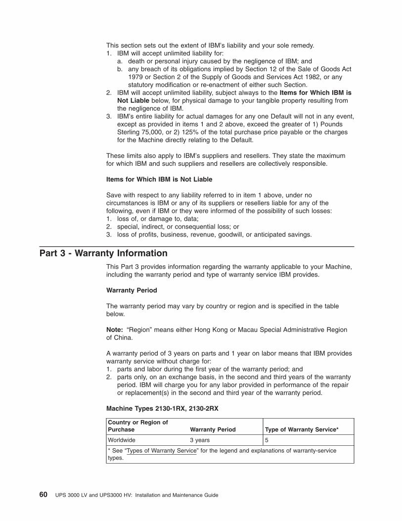
This section sets out the extent of IBM’s liability and your sole remedy.
1. IBM will accept unlimited liability for:
a. death or personal injury caused by the negligence of IBM; and
b. any breach of its obligations implied by Section 12 of the Sale of Goods Act
1979 or Section 2 of the Supply of Goods and Services Act 1982, or any
statutory modification or re-enactment of either such Section.2. IBM will accept unlimited liability, subject always to the Items for Which IBM is
Not Liable below, for physical damage to your tangible property resulting from
the negligence of IBM.
3. IBM’s entire liability for actual damages for any one Default will not in any event,
except as provided in items 1 and 2 above, exceed the greater of 1) Pounds
Sterling 75,000, or 2) 125% of the total purchase price payable or the charges
for the Machine directly relating to the Default.
These limits also apply to IBM’s suppliers and resellers. They state the maximum
for which IBM and such suppliers and resellers are collectively responsible.
Items for Which IBM is Not Liable
Save with respect to any liability referred to in item 1 above, under no
circumstances is IBM or any of its suppliers or resellers liable for any of the
following, even if IBM or they were informed of the possibility of such losses:
1. loss of, or damage to, data;
2. special, indirect, or consequential loss; or
3. loss of profits, business, revenue, goodwill, or anticipated savings.
Part 3 - Warranty Information
This Part 3 provides information regarding the warranty applicable to your Machine,
including the warranty period and type of warranty service IBM provides.
Warranty Period
The warranty period may vary by country or region and is specified in the table
below.
Note: “Region” means either Hong Kong or Macau Special Administrative Region
of China.
A warranty period of 3 years on parts and 1 year on labor means that IBM provides
warranty service without charge for:
1. parts and labor during the first year of the warranty period; and
2. parts only, on an exchange basis, in the second and third years of the warranty
period. IBM will charge you for any labor provided in performance of the repair
or replacement(s) in the second and third year of the warranty period.
Machine Types 2130-1RX, 2130-2RX
Country or Region of
Purchase Warranty Period Type of Warranty Service*
Worldwide 3 years 5
* See “Types of Warranty Service” for the legend and explanations of warranty-service
types.
60 UPS 3000 LV and UPS3000 HV: Installation and Maintenance Guide
Types of Warranty Service
If required, IBM provides repair or exchange service depending on the type of
warranty service specified for your Machine in the above table and as described
below. Warranty service may be provided by your reseller if approved by IBM to
perform warranty service. Scheduling of service will depend upon the time of your
call and is subject to parts availability. Service levels are response time objectives
and are not guaranteed. The specified level of warranty service may not be
available in all worldwide locations, additional charges may apply outside IBM’s
normal service area, contact your local IBM representative or your reseller for
country and location specific information.
1. Customer Replaceable Unit (“CRU”) Service
IBM provides replacement CRUs to you for you to install. CRU information and
replacement instructions are shipped with your Machine and are available from
IBM at any time on your request. Installation of Tier 1 CRUs is your
responsibility. If IBM installs a Tier 1 CRU at your request, you will be charged
for the installation. You may install a Tier 2 CRU yourself or request IBM to
install it, at no additional charge, under the type of warranty service designated
for your Machine. IBM specifies in the materials shipped with a replacement
CRU whether a defective CRU must be returned to IBM. When return is
required, 1) return instructions and a container are shipped with the replacement
CRU, and 2) you may be charged for the replacement CRU if IBM does not
receive the defective CRU within 30 days of your receipt of the replacement.
2. On-site Service
IBM or your reseller will either repair or exchange the failing Machine at your
location and verify its operation. You must provide suitable working area to allow
disassembly and reassembly of the IBM Machine. The area must be clean, well
lit and suitable for the purpose. For some Machines, certain repairs may require
sending the Machine to an IBM service center.
3. Courier or Depot Service*
You will disconnect the failing Machine for collection arranged by IBM. IBM will
provide you with a shipping container for you to return your Machine to a
designated service center. A courier will pick up your Machine and deliver it to
the designated service center. Following its repair or exchange, IBM will arrange
the return delivery of the Machine to your location. You are responsible for its
installation and verification.
4. Customer Carry-In or Mail-In Service
You will deliver or mail as IBM specifies (prepaid unless IBM specifies
otherwise) the failing Machine suitably packaged to a location IBM designates.
After IBM has repaired or exchanged the Machine, IBM will make it available for
your collection or, for Mail-in Service, IBM will return it to you at IBM’s expense,
unless IBM specifies otherwise. You are responsible for the subsequent
installation and verification of the Machine.
5. CRU and On-site Service
This type of Warranty Service is a combination of Type 1 and Type 2 (see
above).
6. CRU and Courier or Depot Service
This type of Warranty Service is a combination of Type 1 and Type 3 (see
above).
7. CRU and Customer Carry-In or Mail-In Service
This type of Warranty Service is a combination of Type 1 and Type 4 (see
above).
Appendix B. IBM Statement of Limited Warranty Z125-4753-08 04/2004 61

When a 5, 6 or 7 type of warranty service is listed, IBM will determine which
type of warranty service is appropriate for the repair.
* This type of service is called ThinkPad EasyServ or EasyServ in some countries.
The IBM Machine Warranty World Wide Web site at http://www.ibm.com/servers/support/machine_warranties/ provides a worldwide overview of IBM’s Limited
Warranty for Machines, a Glossary of IBM definitions, Frequently Asked Questions
(FAQs) and Support by Product (Machine) with links to Product Support pages. The
IBM Statement of Limited Warranty is also available on this site in 29
languages.
To obtain warranty service contact IBM or your IBM reseller. In Canada or the
United States, call 1-800-IBM-SERV (426-7378). In the EU countries, see the
telephone numbers below.
EU Country Telephone List
Phone numbers are subject to change without notice. For the warranty service
contact telephone number in a country subsequently added to the EU and not yet
reflected in the list below, contact IBM in that country or visit the website above for
a current telephone listing.
Austria -- +43-1-24592-5901 Latvia -- +386-61-1796-699
Belgium -- +32-70-23-3392 Lithuania -- +386-61-1796-699
Cyprus -- +357-22-841100 Luxembourg -- +352-298-977-5063
Czech Republic -- +420-2-7213-1316 Malta -- +356-23-4175
Denmark -- +45-4520-8200 Netherlands -- +31-20-514-5770
Estonia -- +386-61-1796-699 Poland -- +48-22-878-6999
Finland -- +358-8001-4260 Portugal -- +351-21-892-7147
France -- +33-238-557-450 Slovakia -- +421-2-4954-1217
Germany -- +49-1805-253553 Slovenia -- +386-1-4796-699
Greece -- +30-210-680-1700 Spain -- +34-91-714-7983
Hungary -- +36-1-382-5720 Sweden -- +46-8-477-4420
Ireland -- +353-1-815-4000 United Kingdom -- +44-0870-550-0900
Italy -- +39-800-820-094
62 UPS 3000 LV and UPS3000 HV: Installation and Maintenance Guide

Appendix C. Notices
This information was developed for products and services offered in the U.S.A.
IBM may not offer the products, services, or features discussed in this document in
other countries. Consult your local IBM representative for information on the
products and services currently available in your area. Any reference to an IBM
product, program, or service is not intended to state or imply that only that IBM
product, program, or service may be used. Any functionally equivalent product,
program, or service that does not infringe any IBM intellectual property right may be
used instead. However, it is the user’s responsibility to evaluate and verify the
operation of any non-IBM product, program, or service.
IBM may have patents or pending patent applications covering subject matter
described in this document. The furnishing of this document does not give you any
license to these patents. You can send license inquiries, in writing, to:
IBM Director of Licensing
IBM Corporation
North Castle Drive
Armonk, NY 10504-1785
U.S.A.
INTERNATIONAL BUSINESS MACHINES CORPORATION PROVIDES THIS
PUBLICATION “AS IS” WITHOUT WARRANTY OF ANY KIND, EITHER EXPRESS
OR IMPLIED, INCLUDING, BUT NOT LIMITED TO, THE IMPLIED WARRANTIES
OF NON-INFRINGEMENT, MERCHANTABILITY OR FITNESS FOR A
PARTICULAR PURPOSE. Some states do not allow disclaimer of express or
implied warranties in certain transactions, therefore, this statement may not apply to
you.
This information could include technical inaccuracies or typographical errors.
Changes are periodically made to the information herein; these changes will be
incorporated in new editions of the publication. IBM may make improvements and/or
changes in the product(s) and/or the program(s) described in this publication at any
time without notice.
Any references in this information to non-IBM Web sites are provided for
convenience only and do not in any manner serve as an endorsement of those
Web sites. The materials at those Web sites are not part of the materials for this
IBM product, and use of those Web sites is at your own risk.
IBM may use or distribute any of the information you supply in any way it believes
appropriate without incurring any obligation to you.
Trademarks
The following terms are trademarks of International Business Machines Corporation
in the United States, other countries, or both:
IBM i5/OS TechConnect
IBM (logo) IBM Systems Director
Active Energy Manager
Tivoli
Active Memory iDataPlex Tivoli Enterprise
Active PCI IntelliStation Update Connector
© Copyright IBM Corp. 2006, 2008 63

Active PCI-X NetBAY Wake on LAN
AIX Netfinity XA-32
Alert on LAN PowerExecutive XA-64
BladeCenter Predictive Failure Analysis X-Architecture
Chipkill ServeRAID XpandOnDemand
e-business logo ServerGuide xSeries
Eserver ServerProven
FlashCopy System x
Intel, Intel Xeon, Itanium, and Pentium are trademarks of Intel Corporation in the
United States, other countries, or both.
Microsoft, Windows, and Windows NT are trademarks of Microsoft Corporation in
the United States, other countries, or both.
Adobe and PostScript are either registered trademarks or trademarks of Adobe
Systems Incorporated in the United States, other countries, or both.
UNIX is a registered trademark of The Open Group in the United States and other
countries.
Java and all Java-based trademarks are trademarks of Sun Microsystems, Inc. in
the United States, other countries, or both.
Adaptec and HostRAID are trademarks of Adaptec, Inc., in the United States, other
countries, or both.
Linux is a registered trademark of Linus Torvalds in the United States, other
countries, or both.
Red Hat, the Red Hat “Shadow Man” logo, and all Red Hat-based trademarks and
logos are trademarks or registered trademarks of Red Hat, Inc., in the United States
and other countries.
Other company, product, or service names may be trademarks or service marks of
others.
Important notes
Processor speed indicates the internal clock speed of the microprocessor; other
factors also affect application performance.
CD or DVD drive speed is the variable read rate. Actual speeds vary and are often
less than the possible maximum.
When referring to processor storage, real and virtual storage, or channel volume,
KB stands for 1024 bytes, MB stands for 1 048 576 bytes, and GB stands for
1 073 741 824 bytes.
When referring to hard disk drive capacity or communications volume, MB stands
for 1 000 000 bytes, and GB stands for 1 000 000 000 bytes. Total user-accessible
capacity can vary depending on operating environments.
64 UPS 3000 LV and UPS3000 HV: Installation and Maintenance Guide

Maximum internal hard disk drive capacities assume the replacement of any
standard hard disk drives and population of all hard disk drive bays with the largest
currently supported drives that are available from IBM.
Maximum memory might require replacement of the standard memory with an
optional memory module.
IBM makes no representation or warranties regarding non-IBM products and
services that are ServerProven®, including but not limited to the implied warranties
of merchantability and fitness for a particular purpose. These products are offered
and warranted solely by third parties.
IBM makes no representations or warranties with respect to non-IBM products.
Support (if any) for the non-IBM products is provided by the third party, not IBM.
Some software might differ from its retail version (if available) and might not include
user manuals or all program functionality.
Product recycling and disposal
This unit must be recycled or discarded according to applicable local and national
regulations. IBM encourages owners of information technology (IT) equipment to
responsibly recycle their equipment when it is no longer needed. IBM offers a
variety of product return programs and services in several countries to assist
equipment owners in recycling their IT products. Information on IBM product
recycling offerings can be found on IBM’s Internet site at http://www.ibm.com/ibm/environment/products/index.shtml.
Esta unidad debe reciclarse o desecharse de acuerdo con lo establecido en la
normativa nacional o local aplicable. IBM recomienda a los propietarios de equipos
de tecnología de la información (TI) que reciclen responsablemente sus equipos
cuando éstos ya no les sean útiles. IBM dispone de una serie de programas y
servicios de devolución de productos en varios países, a fin de ayudar a los
propietarios de equipos a reciclar sus productos de TI. Se puede encontrar
información sobre las ofertas de reciclado de productos de IBM en el sitio web de
IBM http://www.ibm.com/ibm/environment/products/index.shtml.
Notice: This mark applies only to countries within the European Union (EU) and
Norway.
This appliance is labeled in accordance with European Directive 2002/96/EC
concerning waste electrical and electronic equipment (WEEE). The Directive
determines the framework for the return and recycling of used appliances as
applicable throughout the European Union. This label is applied to various products
to indicate that the product is not to be thrown away, but rather reclaimed upon end
of life per this Directive.
Appendix C. Notices 65
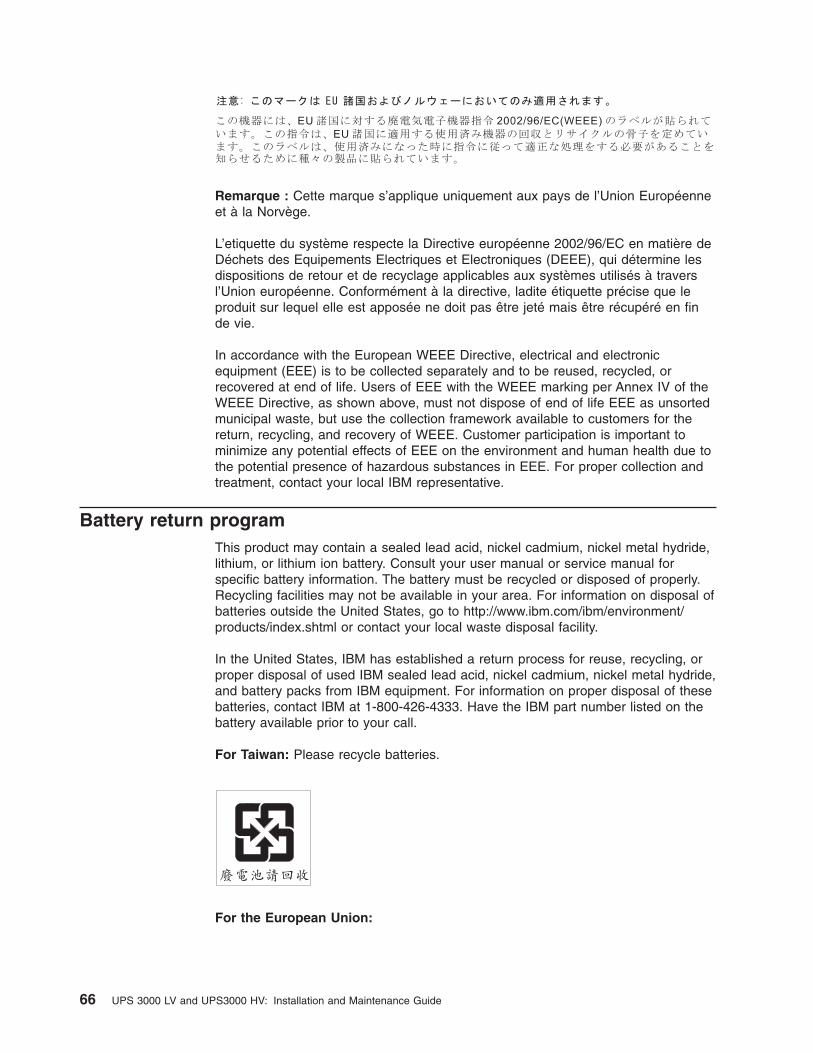
Remarque : Cette marque s’applique uniquement aux pays de l’Union Européenne
et à la Norvège.
L’etiquette du système respecte la Directive européenne 2002/96/EC en matière de
Déchets des Equipements Electriques et Electroniques (DEEE), qui détermine les
dispositions de retour et de recyclage applicables aux systèmes utilisés à travers
l’Union européenne. Conformément à la directive, ladite étiquette précise que le
produit sur lequel elle est apposée ne doit pas être jeté mais être récupéré en fin
de vie.
In accordance with the European WEEE Directive, electrical and electronic
equipment (EEE) is to be collected separately and to be reused, recycled, or
recovered at end of life. Users of EEE with the WEEE marking per Annex IV of the
WEEE Directive, as shown above, must not dispose of end of life EEE as unsorted
municipal waste, but use the collection framework available to customers for the
return, recycling, and recovery of WEEE. Customer participation is important to
minimize any potential effects of EEE on the environment and human health due to
the potential presence of hazardous substances in EEE. For proper collection and
treatment, contact your local IBM representative.
Battery return program
This product may contain a sealed lead acid, nickel cadmium, nickel metal hydride,
lithium, or lithium ion battery. Consult your user manual or service manual for
specific battery information. The battery must be recycled or disposed of properly.
Recycling facilities may not be available in your area. For information on disposal of
batteries outside the United States, go to http://www.ibm.com/ibm/environment/products/index.shtml or contact your local waste disposal facility.
In the United States, IBM has established a return process for reuse, recycling, or
proper disposal of used IBM sealed lead acid, nickel cadmium, nickel metal hydride,
and battery packs from IBM equipment. For information on proper disposal of these
batteries, contact IBM at 1-800-426-4333. Have the IBM part number listed on the
battery available prior to your call.
For Taiwan: Please recycle batteries.
For the European Union:
66 UPS 3000 LV and UPS3000 HV: Installation and Maintenance Guide

Notice: This mark applies only to countries within the European Union (EU).
Batteries or packaging for batteries are labeled in accordance with European
Directive 2006/66/EC concerning batteries and accumulators and waste batteries
and accumulators. The Directive determines the framework for the return and
recycling of used batteries and accumulators as applicable throughout the European
Union. This label is applied to various batteries to indicate that the battery is not to
be thrown away, but rather reclaimed upon end of life per this Directive.
Les batteries ou emballages pour batteries sont étiquetés conformément aux
directives européennes 2006/66/EC, norme relative aux batteries et accumulateurs
en usage et aux batteries et accumulateurs usés. Les directives déterminent la
marche à suivre en vigueur dans l’Union Européenne pour le retour et le recyclage
des batteries et accumulateurs usés. Cette étiquette est appliquée sur diverses
batteries pour indiquer que la batterie ne doit pas être mise au rebut mais plutôt
récupérée en fin de cycle de vie selon cette norme.
In accordance with the European Directive 2006/66/EC, batteries and accumulators
are labeled to indicate that they are to be collected separately and recycled at end
of life. The label on the battery may also include a chemical symbol for the metal
concerned in the battery (Pb for lead, Hg for mercury, and Cd for cadmium). Users
of batteries and accumulators must not dispose of batteries and accumulators as
unsorted municipal waste, but use the collection framework available to customers
for the return, recycling, and treatment of batteries and accumulators. Customer
participation is important to minimize any potential effects of batteries and
accumulators on the environment and human health due to the potential presence
of hazardous substances. For proper collection and treatment, contact your local
IBM representative.
This notice is provided in accordance with Royal Decree 106/2008 of Spain: The
retail price of batteries, accumulators, and power cells includes the cost of the
environmental management of their waste.
For California:
Perchlorate material – special handling may apply. See http://www.dtsc.ca.gov/hazardouswaste/perchlorate/.
Appendix C. Notices 67

The foregoing notice is provided in accordance with California Code of Regulations
Title 22, Division 4.5 Chapter 33. Best Management Practices for Perchlorate
Materials. This product/part may include a lithium manganese dioxide battery which
contains a perchlorate substance.
Electronic emission notices
Federal Communications Commission (FCC) statement
Note: This equipment has been tested and found to comply with the limits for a
Class A digital device, pursuant to Part 15 of the FCC Rules. These limits are
designed to provide reasonable protection against harmful interference when the
equipment is operated in a commercial environment. This equipment generates,
uses, and can radiate radio frequency energy and, if not installed and used in
accordance with the instruction manual, may cause harmful interference to radio
communications. Operation of this equipment in a residential area is likely to cause
harmful interference, in which case the user will be required to correct the
interference at his own expense.
Properly shielded and grounded cables and connectors must be used in order to
meet FCC emission limits. IBM is not responsible for any radio or television
interference caused by using other than recommended cables and connectors or by
unauthorized changes or modifications to this equipment. Unauthorized changes or
modifications could void the user’s authority to operate the equipment.
This device complies with Part 15 of the FCC Rules. Operation is subject to the
following two conditions: (1) this device may not cause harmful interference, and (2)
this device must accept any interference received, including interference that may
cause undesired operation.
Industry Canada Class A emission compliance statement
This Class A digital apparatus complies with Canadian ICES-003.
Avis de conformité à la réglementation d’Industrie Canada
Cet appareil numérique de la classe A est conforme à la norme NMB-003 du
Canada.
Australia and New Zealand Class A statement
Attention: This is a Class A product. In a domestic environment this product may
cause radio interference in which case the user may be required to take adequate
measures.
United Kingdom telecommunications safety requirement
Notice to Customers
This apparatus is approved under approval number NS/G/1234/J/100003 for indirect
connection to public telecommunication systems in the United Kingdom.
European Union EMC Directive conformance statement
This product is in conformity with the protection requirements of EU Council
Directive 2004/108/EC on the approximation of the laws of the Member States
relating to electromagnetic compatibility. IBM cannot accept responsibility for any
68 UPS 3000 LV and UPS3000 HV: Installation and Maintenance Guide

failure to satisfy the protection requirements resulting from a nonrecommended
modification of the product, including the fitting of non-IBM option cards.
This product has been tested and found to comply with the limits for Class A
Information Technology Equipment according to CISPR 22/European Standard EN
55022. The limits for Class A equipment were derived for commercial and industrial
environments to provide reasonable protection against interference with licensed
communication equipment.
Attention: This is a Class A product. In a domestic environment this product may
cause radio interference in which case the user may be required to take adequate
measures.
European Community contact:
IBM Technical Regulations
Pascalstr. 100, Stuttgart, Germany 70569
Telephone: 0049 (0)711 785 1176
Fax: 0049 (0)711 785 1283
E-mail: [email protected]
Taiwanese Class A warning statement
Chinese Class A warning statement
Japanese Voluntary Control Council for Interference (VCCI) statement
Appendix C. Notices 69

Korean Class A warning statement
70 UPS 3000 LV and UPS3000 HV: Installation and Maintenance Guide

Index
AAlarm reset button 18
assistance, getting 43
attention notices 4
audible alarm, silencing 39
Bbattery
care 35
storing 36
Battery mode 19
battery module, replacing (trained service technician
only) 37
battery return program 66
Battery service LED 17
battery, connecting internal 10
buttonsAlarm reset 18
Off 17
On 17
Bypass mode 19
Ccaution statements 4
Class A electronic emission notice 68
Configuration mode 20
Configuration mode LEDs and options 21
configuring Web/SNMP card locallycard settings and event log summary 31
connecting to terminal or computer 28
e-mail notification 31
setting card control group 30
setting event actions 30
setting external contact monitoring 31
setting IP address of primary and secondary date
server 30
setting IP address, gateway address, and MIB
system group 29
setting superuser name and password 31
setting trap receivers 30
setting uninterruptible power supply information 31
setting Web site links 31
setting write access managers 30
setup 28
configuring Web/SNMP card remotelyadding routing condition in the computer 32
setting up the network configuration 32
connectinginternal battery 10
uninterruptible power supply and extended battery
module (rack configuration) 12
uninterruptible power supply and extended battery
module (tower configuration) 13
CRU listing 35
Ddanger statements 4
documentation CD 1
Eelectronic emission Class A notice 68
electronics module, replacing (trained service technician
only) 36
extended battery module, tower configuration 6
FFCC Class A notice 68
firmware updates 1
front view LEDs and controls 17
FRU listing 35
GGeneral alarm LED 17
getting help 43
Hhardware service and support 44
help, getting 43
IIBM Support Line 44
important notices 4
internal battery, connecting 10
inventory checklist 5
LLEDs
Battery service 17
General alarm 17
Load level 18
On battery 17
Power-on 17
Site wiring 17
Web/SNMP card 27
Load level LEDs 18
load segments 23
NNormal mode 19
notes 4
notes, important 64
notices 63
electronic emission 68
FCC, Class A 68
© Copyright IBM Corp. 2006, 2008 71
notices and statements 4
OOff button 17
On battery LED 17
On button 17
online documentation 1
operating modesBattery 19
Bypass 19
Configuration 20
Normal 19
Standby 19
PPower-on LED 17
product recycling and disposal 65
Rrack installation 5
rear view controls and power 18
recycling and disposal, product 65
remote emergency power-offconnecting a switch 14
overview 14
replaceable components 35
replacing battery module (trained service technician
only) 37
replacing electronics module (trained service technician
only) 36
Ssilencing audible alarm 39
Site wiring LED 17
software service and support 44
specifications, uninterruptible power supply 3
Standby mode 19
starting on battery 22
statements and notices 4
support, web site 43
switch, remote emergency power-off, connecting 14
Ttelephone numbers 44
tower configurationoverview 6
uninterruptible power supply and extended battery
module 8
uninterruptible power supply and two or more
extended battery modules 10
uninterruptible power supply only 7
trademarks 63
troubleshootingaudible alarms 39
guide 39
turning off uninterruptible power supply 22
turning on uninterruptible power supply 22
Uuninterruptible power supply
audible alarms 39
battery care 35
CRU and FRU listing 35
front view LEDs and controls 17
inventory checklist 5
load segments 23
rear view controls and power 18
replaceable components 35
replacing battery module (trained service technician
only) 37
replacing electronics module (trained service
technician only) 36
specifications 3
starting on battery 22
storing battery 36
tower configuration 6
troubleshooting guide 39
turning off 22
turning on 22
United States electronic emission Class A notice 68
United States FCC Class A notice 68
Wweb site
publication ordering 43
support 43
support line, telephone numbers 44
Web/SNMP cardconfiguring locally 28
configuring remotely 32
features 25
LEDs and controls 27
overview 25
system application 26
using in serial pass-through mode 33
72 UPS 3000 LV and UPS3000 HV: Installation and Maintenance Guide


����
Part Number: 43W7864
Printed in USA
(1P) P/N: 43W7864