Embed Size (px)
Citation preview
INSTALLATION AND HARDWARE GUIDE
AAA-130U2 SERIESULTRA2 SCSI RAID CARD
Adaptec, Inc.691 South Milpitas BoulevardMilpitas, CA 95035
R
© 1999 Adaptec, Inc.All rights reserved. Adaptec, and the Adaptec logo are trademarks of Adaptec, Inc. which may be regis-tered in some jurisdictions.
Printed in SingaporeSTOCK NO.: 512278-00, Rev. A RQ 2/99
R
▼ ▼ ▼ ▼ AAA-130U2 SeriesUltra2 SCSI RAID Card
Installation and Hardware Guide
Copyright© 1999 Adaptec, Inc. All rights reserved. No part of this publication may be repro-duced, stored in a retrieval system, or transmitted in any form or by any means, elec-tronic, mechanical, photocopying, recording or otherwise, without the prior written consent of Adaptec, Inc., 691 South Milpitas Blvd., Milpitas, CA 95035.
TrademarksAdaptec, the Adaptec logo, AAA, AHA, AIC, Array1000, ARRAYCONFIG, CI/O, Adaptec CI/O Management Software, and SCSISelect are trademarks of Adaptec, Inc. which may be registered in some jurisdictions.
Windows is a registered trademark and Windows NT is a trademark of Microsoft Cor-poration in the U.S. and other countries used under license.
All other trademarks are owned by their respective owners.
ChangesThe material in this document is for information only and is subject to change with-out notice. While reasonable efforts have been made in the preparation of this docu-ment to assure its accuracy, Adaptec, Inc. assumes no liability resulting from errors or omissions in this document, or from the use of the information contained herein.
Adaptec reserves the right to make changes in the product design without reservation and without notification to its users.
DisclaimerIF THIS PRODUCT DIRECTS YOU TO COPY MATERIALS, YOU MUST HAVE PER-MISSION FROM THE COPYRIGHT OWNER OF THE MATERIALS TO AVOID VIO-LATING THE LAW WHICH COULD RESULT IN DAMAGES OR OTHER REMEDIES.
ii
Federal Communications Commission Radio Frequency Interference StatementWARNING: Changes or modifications to this unit not expressly approved by the party responsi-ble for compliance could void the user’s authority to operate the equipment.
This equipment has been tested and found to comply with the limits for a Class B digital device, pursuant to Part 15 of the FCC rules. These limits are designed to provide reasonable protection against harmful interference in a residential installation. This equipment generates, uses, and can radiate radio frequency energy, and if not installed and used in accordance with the instruction manual, may cause harmful interference to radio communications. However, there is no guarantee that interference will not occur in a particular installation. However, if this equipment does cause interference to radio or television equipment reception, which can be determined by turning the equipment off and on, the user is encouraged to try to correct the interference by one or more of the following measures:
• Reorient or relocate the receiving antenna.
• Increase the separation between equipment and receiver.
• Connect the equipment to an outlet on a circuit different from that to which the receiver is connected.
• Consult the dealer or an experienced radio/television technician for help.
Use a shielded and properly grounded I/O cable and power cable to ensure compliance of this unit to the specified limits of the rules.
This device complies with part 15 of the FCC rules. Operation is subject to the following two con-ditions: (1) this device may not cause harmful interference and (2) this device must accept any interference received, including interference that may cause undesired operation.
Canadian Compliance StatementThis Class B digital apparatus meets all requirements of the Canadian Interference-Causing Equipment Regulations.
Cet appareil numérique de la classe B respecte toutes les exigences du Règlement sur le matérial brouilleur du Canada.
Adaptec, Inc.
Tested To ComplyWith FCC Standards
FOR HOME OR OFFICE USE
AAA-131U2,AAA-133U2
iii

▼ ▼ ▼ ▼ Contents
1 IntroductionSystem Requirements 1-2Installation Overview 1-3
2 Installing the HardwareAAA-131U2/133U2 RAID Card Layout 2-2Installing DIMM Memory 2-3Installing the AAA-131U2/133U2 2-4
Connecting the LED Activity Indicator 2-5Setting Up SCSI Devices 2-6
Check the SCSI IDs 2-6Terminate the Ends 2-7Additional Hints for Connecting SCSI Devices 2-8
Connecting SCSI Devices 2-9Internal Ultra2 SCSI Connector (68-pin) 2-10Internal Ultra SCSI Connector (50-pin) 2-13External Ultra2 SCSI Connector (68-pin) 2-16External SCSI Array Enclosures (Storage
Subsystems) 2-18Configuring the AAA-131U2/133U2 2-19
3 Creating an Array With the ARRAYCONFIG U2 UtilityCreating an Array 3-2
Creating an Array with Express Setup 3-2Creating an Array with Custom Setup 3-4
Making the Array Bootable 3-8
v
AAA-130U2 Series Installation and Hardware Guide
4 Installing the Software Driver for Windows NTInstalling the Array1000U2 Driver for Windows NT 4-2
Installing the Driver When Installing Windows NT 4-2Installing the Driver When Windows NT is Already
Installed 4-4Windows NT Installation and Configuration Notes 4-5
5 Installing the Software Driver for Novell NetWareInstalling the Array1000U2 Driver for Novell NetWare 5-2
Installing the Driver When Installing NetWare 5-2Installing the Driver When NetWare is Already
Installed 5-7Netware Installation and Configuration Notes 5-8
6 Installing the Software Driver for SCO UnixWareInstalling the Array1000U2 Driver for UnixWare 6-2
Installing the Driver When Installing SCO UnixWare 6-2
Installing the Driver When SCO UnixWare is Already Installed 6-3
A Using SCSI Select and Disk UtilitiesSCSISelect Default Settings A-2Starting the SCSISelect Utility A-3
Using SCSISelect Menus A-3Exiting SCSISelect A-3
Using the SCSI Disk Utilities A-4SCSISelect Settings A-5
SCSI Bus Interface Definitions A-5SCSI Device Configuration A-5Additional Options A-6
B TroubleshootingTroubleshooting Checklist B-1Windows NT Troubleshooting B-2
Error Messages While Setting Up Windows NT B-2
vi
Contents
C Using a CD-ROM DriveUsing a CD-ROM Drive with DOS C-1
D Obtaining SCSI CablesExternal Cables D-2
External Connector Diagrams D-2Internal Ribbon Cables D-2
Internal Connector Diagrams D-2
Index
❒
vii

ì▼ ▼ ▼ ▼
IntroductionIn this Chapter
The Adaptec® AAA™-131U2 and AAA-133U2 Ultra2 SCSI RAID cards provide powerful disk array support in systems that have a PCI bus. The AAA-131U2 and AAA-133U2 are collectively referred to as “AAA-131U2/133U2” in this document. Here is a summary of the two models:
■ The AAA-131U2 is a single-channel, half-size PCI RAID card, with 50-pin standard and 68-pin Ultra2 internal connectors and a 68-pin external Ultra2 connector.
■ The AAA-133U2 is a three-channel, full-size PCI RAID card with 68-pin internal Ultra2 connectors for Channel A, B, and C; 68-pin external Ultra2 connector for Channel A; and 50-pin internal connector for Channel A.
This Installation and Hardware Guide explains how to install the AAA-131U2/133U2, connect SCSI devices to it, run the ARRAYCONFIG™ U2 Utility to create the first array for a bootable array configuration, and then install the software driver for your operating system.
➤ System Requirements 1-2
➤ Installation Overview 1-3
1-1
AAA-130U2 Series Installation and Hardware Guide
Use the Adaptec CI/O Management Software™, which is included with the AAA-131U2/133U2, to create additional arrays (CI/O is required for array management in order to provide the proper level of fault tolerance and event notification). Refer to the Adaptec CI/O Management Software User’s Guide for instructions on installing and using the software.
System RequirementsThe minimum system requirements for the AAA-131U2/133U2 are
■ PCI-based 90-MHz Pentium or equivalent motherboard with PCI-to-PCI bridge support
■ An available half-length (for AAA-131U2) or full-length(for AAA-133U2), unobstructed PCI slot that supports Bus Mastering
■ A minimum of one SCSI hard disk
■ A standard 168-pin EDO 3.3v, 60ns or faster DIMM installed on the adapter. (A DIMM is typically pre-installed.) See the Adaptec Web Site at http://www.adaptec.com/raid for a list of approved DIMMs and vendors
■ Five MBytes of free hard disk space for the AAA-131U2/133U2 software (five MBytes of free hard disk space on the Windows system disk are also required for the temporary files created during installation of the software)
■ Windows NT™ 4.0 Server, Windows NT 4.0 Workstation, Novell NetWare 4.11, 4.2, or 5.0, or UnixWare 7.0.
■ A 3.5-inch 1.44-MByte primary (boot) floppy disk drive
■ 64 MBytes or more of system memory.
Caution: An Uninterruptable Power Supply (UPS) is a key feature for system fault tolerance. It is possible to lose data due to power failure or power brown outs. In order to pre-vent errors or data loss due to power failure, Adaptec strongly recommends that a UPS be installed to support your system.
1-2
Introduction
Installation OverviewTo install AAA-131U2/133U2 hardware and software, follow these steps:
■ Install the AAA-131U2/133U2 in the system. (Chapter 2)
■ Connect SCSI devices to the AAA-131U2/133U2. (Chapter 2)
■ Create the first bootable array using the ARRAYCONFIG U2 utility. (Chapter 3)
■ Install the appropriate Array1000U2 software driver for your operating system. (Chapter 4, Chapter 5, and Chapter 6)
■ Install the Adaptec CI/O Management Software. (Adaptec CI/O Management Software User’s Guide)
Note: Before proceeding with installation, review the readcio.txt file found in the Adaptec CI/O Management Software CD-ROM and the relnote.txt file found in the root directory of the Array1000U2 driver diskette.
❒
1-3

ë▼ ▼ ▼ ▼
Installing the HardwareIn this Chapter
This chapter explains how to install the AAA-131U2/133U2 and connect SCSI devices to it.
WARNING: Before handling the AAA-131U2/133U2 and any other electronic component, ground yourself by touching an unpainted metal surface on your computer chassis.
➤ AAA-131U2/133U2 RAID Card Layout 2-2
➤ Installing DIMM Memory 2-3
➤ Installing the AAA-131U2/133U2 2-4
➤ Setting Up SCSI Devices 2-6
➤ Connecting SCSI Devices 2-9
➤ Configuring the AAA-131U2/133U2 2-19
2-1
AAA-130U2 Series Installation and Hardware Guide
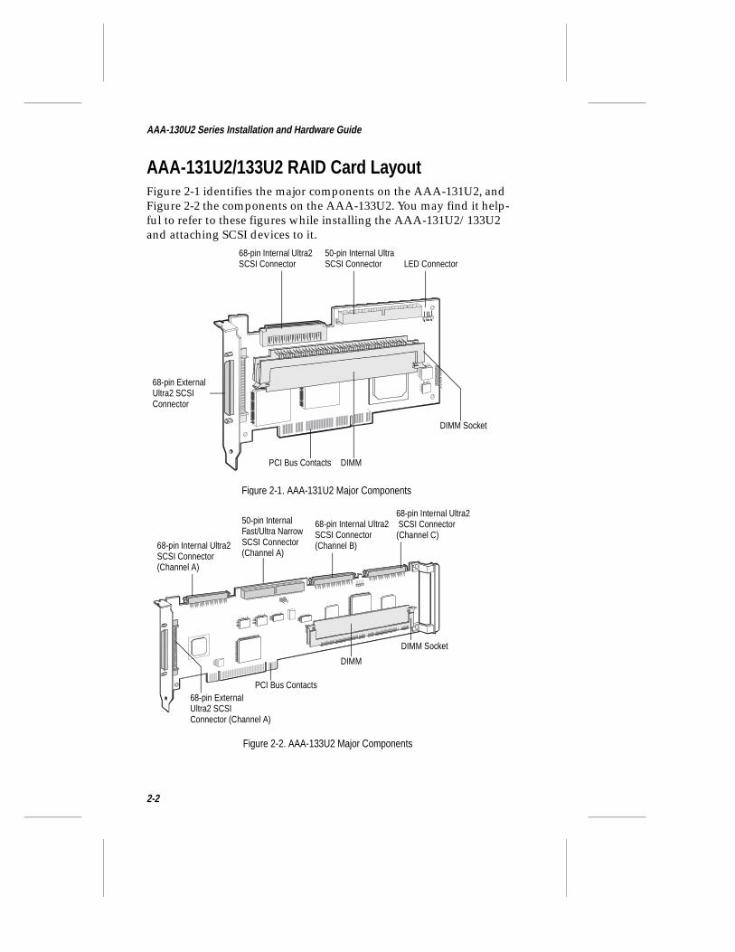
AAA-131U2/133U2 RAID Card LayoutFigure 2-1 identifies the major components on the AAA-131U2, and Figure 2-2 the components on the AAA-133U2. You may find it help-ful to refer to these figures while installing the AAA-131U2/133U2 and attaching SCSI devices to it.
Figure 2-1. AAA-131U2 Major Components
68-pin Internal Ultra2 SCSI Connector
50-pin Internal Ultra SCSI Connector
DIMM Socket
PCI Bus Contacts
LED Connector
68-pin ExternalUltra2 SCSIConnector
DIMM
Figure 2-2. AAA-133U2 Major Components
50-pin InternalFast/Ultra Narrow SCSI Connector(Channel A)
68-pin Internal Ultra2 SCSI Connector(Channel B)
68-pin Internal Ultra2 SCSI Connector(Channel C)
DIMM Socket
PCI Bus Contacts68-pin ExternalUltra2 SCSIConnector (Channel A)
DIMM
68-pin Internal Ultra2 SCSI Connector(Channel A)
2-2
Installing the Hardware
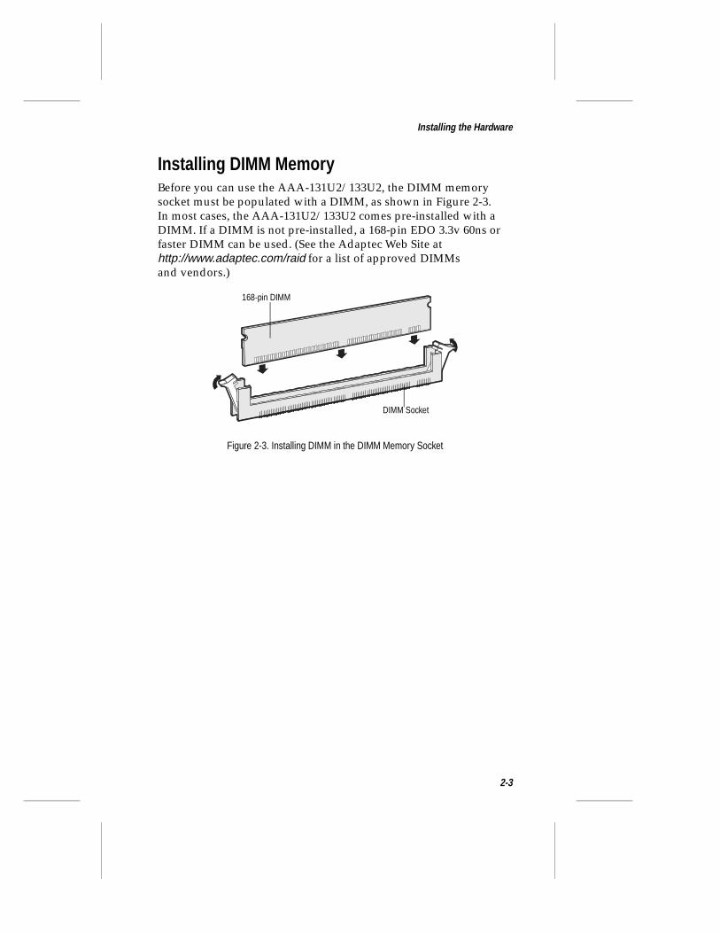
Installing DIMM MemoryBefore you can use the AAA-131U2/133U2, the DIMM memory socket must be populated with a DIMM, as shown in Figure 2-3. In most cases, the AAA-131U2/133U2 comes pre-installed with a DIMM. If a DIMM is not pre-installed, a 168-pin EDO 3.3v 60ns or faster DIMM can be used. (See the Adaptec Web Site at http://www.adaptec.com/raid for a list of approved DIMMs and vendors.)
Figure 2-3. Installing DIMM in the DIMM Memory Socket
168-pin DIMM
DIMM Socket
2-3
AAA-130U2 Series Installation and Hardware Guide
Installing the AAA-131U2/133U2Follow these steps to install the AAA-131U2/133U2:
Note: If you are installing the AAA-131U2/133U2 in an existing system, back up all data before continuing with installation.
1 Turn OFF power to the computer and disconnect the power cord.
2 Remove the cover from the computer case.
3 Locate an unused, unobstructed, PCI expansion slot and remove the expansion slot cover. (The expansion slot must be Rev. 2.1 or higher compliant and support bus mastering.) Save the slot cover screw for use in Step 4.
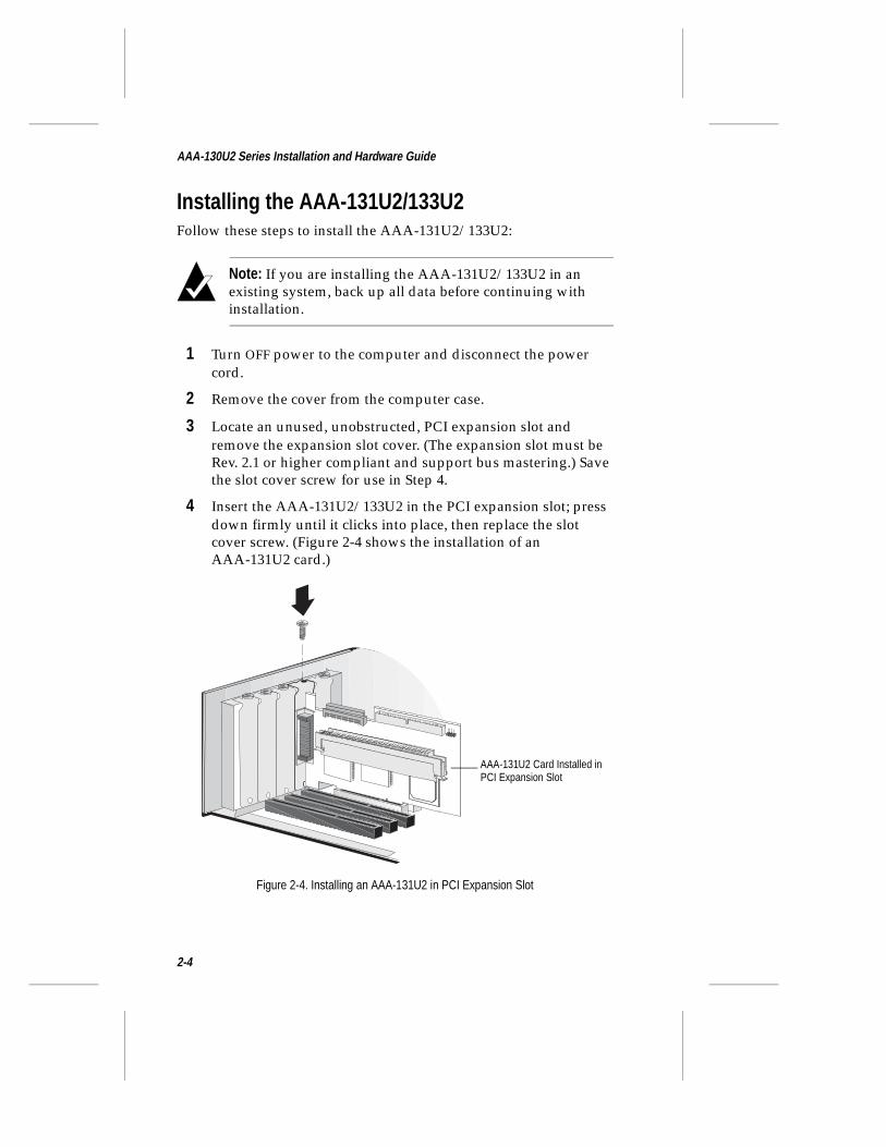
4 Insert the AAA-131U2/133U2 in the PCI expansion slot; press down firmly until it clicks into place, then replace the slot cover screw. (Figure 2-4 shows the installation of an AAA-131U2 card.)
AAA-131U2 Card Installed in PCI Expansion Slot
Figure 2-4. Installing an AAA-131U2 in PCI Expansion Slot
2-4
Installing the Hardware
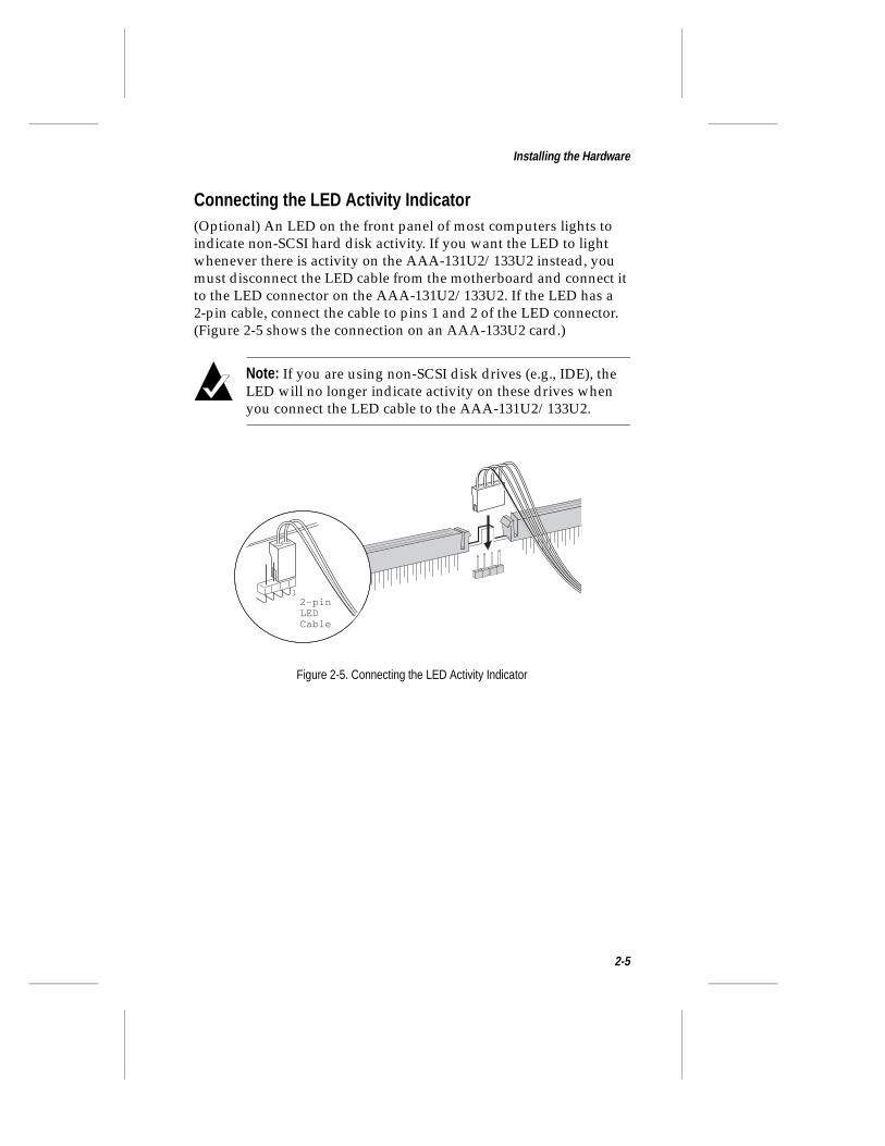
Connecting the LED Activity Indicator(Optional) An LED on the front panel of most computers lights to indicate non-SCSI hard disk activity. If you want the LED to light whenever there is activity on the AAA-131U2/133U2 instead, you must disconnect the LED cable from the motherboard and connect it to the LED connector on the AAA-131U2/133U2. If the LED has a 2-pin cable, connect the cable to pins 1 and 2 of the LED connector. (Figure 2-5 shows the connection on an AAA-133U2 card.)
Note: If you are using non-SCSI disk drives (e.g., IDE), the LED will no longer indicate activity on these drives when you connect the LED cable to the AAA-131U2/133U2.
12-pinLEDCable
Figure 2-5. Connecting the LED Activity Indicator
2-5
AAA-130U2 Series Installation and Hardware Guide
Setting Up SCSI DevicesSetting up SCSI devices before attaching them to the AAA-131U2/133U2 typically involves setting SCSI IDs and termination, mount-ing internal devices inside your computer or external array enclo-sure, and connecting power cables to each device. Since setup can vary from device to device, always refer to the device’s documenta-tion for specific instructions. Below are some guidelines for setting SCSI IDs and termination on your devices. Additional installation hints are also provided to help you install your devices.
Note: If you refer to the device’s documentation for installa-tion instructions, be sure to return to this document to con-tinue with installation of the software included in the package.
Check the SCSI IDsEach device attached to a SCSI channel on the AAA-131U2/133U2, as well as the SCSI channel itself, must be assigned a unique SCSI ID number from 0 to 15—no duplicate IDs are permitted on a channel. ID numbers don’t have to be sequential, as long as the channel and each device has a different number.
■ We recommend that you leave each RAID card channel set to its default setting of SCSI ID 7.
■ SCSI ID 7 has the highest priority on the channel. The priority of the remaining IDs, in descending order, is 6 to 0, then 15 to 8.
■ If you have 8-bit SCSI devices, they must use SCSI IDs 0, 1, 2, 3, 4, 5, or 6. (To change the SCSI ID on your hard disk and other SCSI devices, refer to the device’s documentation.)
■ If you wish to use a single SCSI disk drive (instead of an array) as your boot device, we recommend that you set the SCSI ID for the device to zero. Most SCSI hard disks come from the fac-tory preset to ID 0.
■ The IDs for internal devices are usually set with jumpers; external devices are usually set with a switch on the back of the device.
2-6
Installing the Hardware
Terminate the EndsTo ensure reliable communication on the SCSI bus, terminators must be installed (or enabled) on the devices at the physical ends of each SCSI channel. The devices between the physical ends of each SCSI channel must have the terminator removed (or disabled).
Terminating SCSI Channels on the AAA-131U2/133U2 RAID CardTermination on the AAA-131U2/133U2 itself is controlled via the SCSISelect™ utility. We recommend that you leave each channel on the AAA-131U2/133U2 set to its default setting of Auto Mode (the terminators are enabled or disabled according to the SCSI connectors in use). If you want to manually disable the AAA-131U2/133U2 termination setting, see Chapter A, Using SCSISelect and Disk Utilities.
Terminating SCSI DevicesOn most internal SCSI devices the termination setting is controlled by setting a jumper or a switch, or by physically removing or installing a resistor module(s). On most external SCSI devices, termination is controlled by installing or removing a terminating plug (see Figures 2-14 and 2-15 on page 2-17). Read the device’s doc-umentation to determine how to enable or disable termination on your particular device.
The internal SCSI cables supplied in an Adaptec AAA-131U2/133U2 kit have a terminator attached. If you have this type of cable, disable termination on all internal SCSI devices connected to the cable. In general, we recommend that you terminate the internal cable instead of terminating the SCSI devices. If you are using an external array enclosure, we recommend that you terminate the SCSI back-plane or install an active terminator on the second SCSI connector on the rear panel instead of terminating the individual SCSI devices. If you follow these recommendations, SCSI bus termination will not be affected when you remove or replace SCSI devices.
Note: We recommend that you enable termination power on all SCSI devices in the system so that termination power will still be supplied if you replace one or more drives on the SCSI bus.
2-7
AAA-130U2 Series Installation and Hardware Guide
Additional Hints for Connecting SCSI Devices
All SCSI Devices
■ If you are booting your system from a single SCSI hard disk or bootable array, the boot order (or virtual device order) of the hard disk or array must be set to 0. (See Making the Array Boota-ble on page 3-8.)
■ Enable termination power on all SCSI devices in the system so that if you remove a drive that is supplying termination power other devices will still provide it.
■ Symptoms of SCSI cabling-related problems are drives not being recognized, drives locking up, or drives that deactivate.
■ Use good-quality SCSI cabling, and minimize the stub lengths. Good-quality cables should not be limp when you pick them up. (See Appendix D, Obtaining SCSI Cables for additional information.)
Cable Lengths
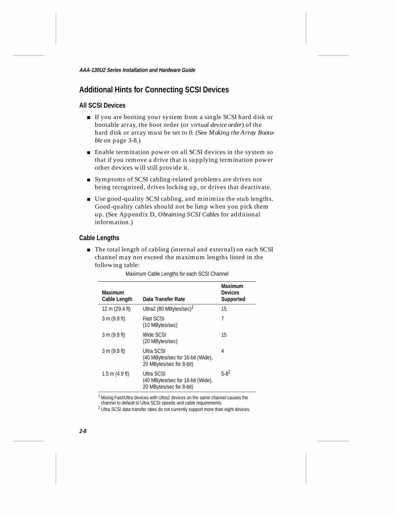
■ The total length of cabling (internal and external) on each SCSI channel may not exceed the maximum lengths listed in the following table:
Maximum Cable Lengths for each SCSI Channel
Maximum Cable Length Data Transfer Rate
Maximum Devices Supported
12 m (29.4 ft) Ultra2 (80 MBytes/sec)1
1 Mixing Fast/Ultra devices with Ultra2 devices on the same channel causes the channel to default to Ultra SCSI speeds and cable requirements.
15
3 m (9.8 ft) Fast SCSI(10 MBytes/sec)
7
3 m (9.8 ft) Wide SCSI(20 MBytes/sec)
15
3 m (9.8 ft) Ultra SCSI(40 MBytes/sec for 16-bit (Wide),20 MBytes/sec for 8-bit)
4
1.5 m (4.9 ft) Ultra SCSI(40 MBytes/sec for 16-bit (Wide),20 MBytes/sec for 8-bit)
5-82
2 Ultra SCSI data transfer rates do not currently support more than eight devices.
2-8
Installing the Hardware
Connecting SCSI DevicesThe AAA-131U2/133U2 supports both internal and external SCSI devices. Each channel supports up to 15 SCSI devices—Ultra2 SCSI devices alone or a combination of Ultra2 and Ultra SCSI devices. Using Adaptec SpeedFlex™ technology, the 50-pin narrow connector on Channel A supports up to seven Fast/Narrow SCSI devices without affecting the performance of Ultra2 devices connected to Channel A internal and external Ultra2 connectors. Before connect-ing devices to the AAA-131U2/133U2, be sure to also review Setting Up SCSI Devices on page 2-6.
Note: We recommend keeping Ultra2 devices on separate channels from non-Ultra2 devices. Peak transfer rates on Ultra2 channels are 80 MBytes/sec. Connecting a non-Ultra2 device to an Ultra2 SCSI channel limits the entire channel to lower performance levels (up to 40 MBytes/sec).
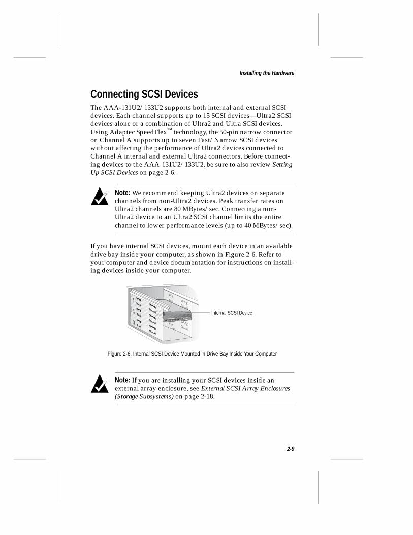
If you have internal SCSI devices, mount each device in an available drive bay inside your computer, as shown in Figure 2-6. Refer to your computer and device documentation for instructions on install-ing devices inside your computer.
Note: If you are installing your SCSI devices inside an external array enclosure, see External SCSI Array Enclosures (Storage Subsystems) on page 2-18.
Figure 2-6. Internal SCSI Device Mounted in Drive Bay Inside Your Computer
Internal SCSI Device
2-9
AAA-130U2 Series Installation and Hardware Guide
Internal Ultra2 SCSI Connector (68-pin)Use the internal Ultra2 SCSI connector to connect internal Ultra2 and Ultra SCSI devices. The AAA-131U2 has one internal Ultra2 SCSI connector (Channel A); and the AAA-133U2 has three (Channels A, B, and C).
Note: We recommend keeping Ultra2 devices on separate channels from non-Ultra2 devices. Peak transfer rates on Ultra2 channels are 80 MBytes/sec. Connecting a non-Ultra2 device to an Ultra2 SCSI channel limits the entire channel to lower performance levels (up to 40 MBytes/sec).
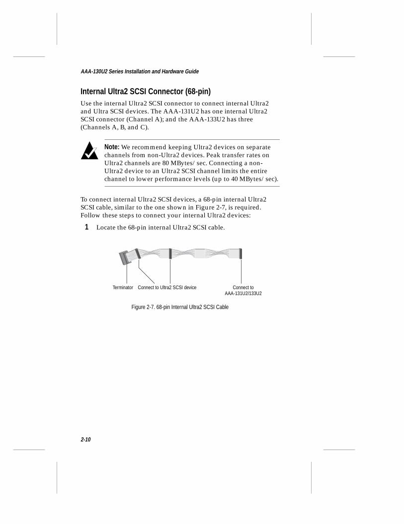
To connect internal Ultra2 SCSI devices, a 68-pin internal Ultra2 SCSI cable, similar to the one shown in Figure 2-7, is required. Follow these steps to connect your internal Ultra2 devices:
1 Locate the 68-pin internal Ultra2 SCSI cable.
Connect to Ultra2 SCSI device Connect to AAA-131U2/133U2
Terminator
Figure 2-7. 68-pin Internal Ultra2 SCSI Cable
2-10
Installing the Hardware
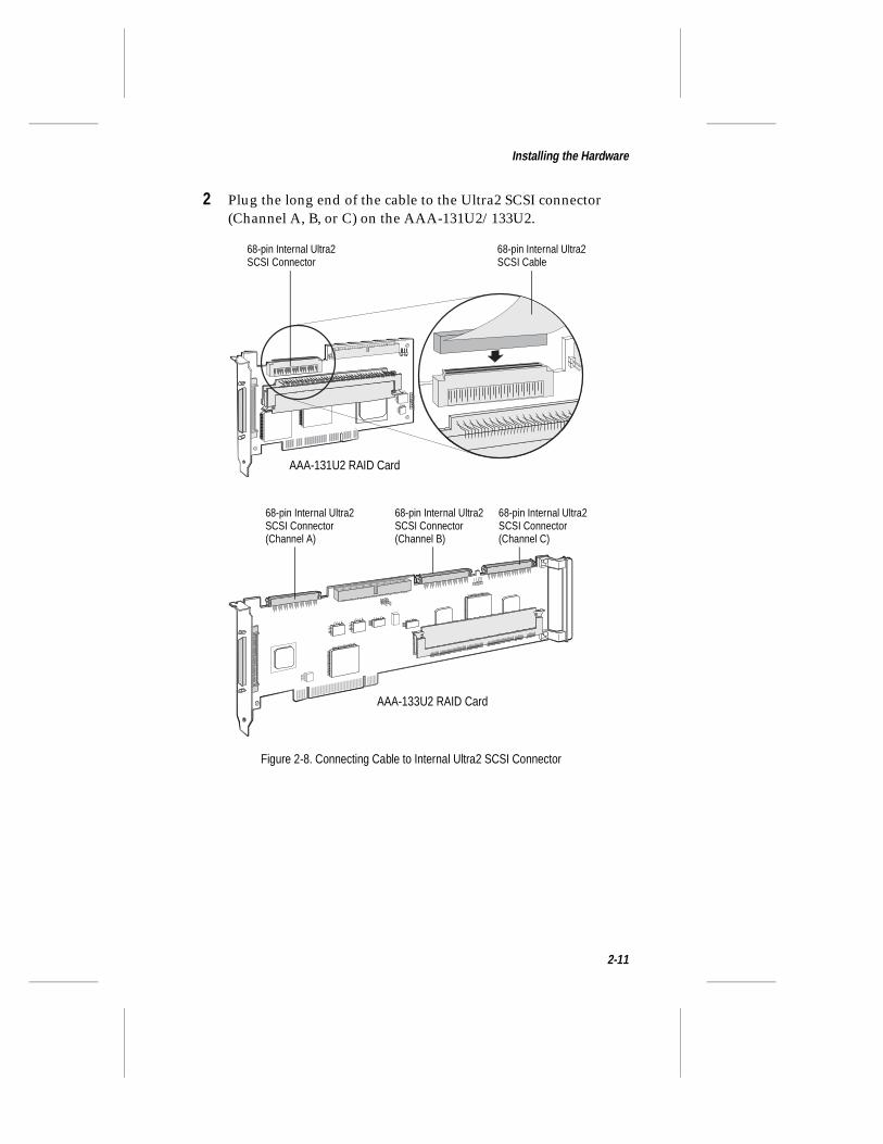
2 Plug the long end of the cable to the Ultra2 SCSI connector (Channel A, B, or C) on the AAA-131U2/133U2.
Figure 2-8. Connecting Cable to Internal Ultra2 SCSI Connector
68-pin Internal Ultra2 SCSI Connector
68-pin Internal Ultra2 SCSI Cable
AAA-131U2 RAID Card
AAA-133U2 RAID Card
68-pin Internal Ultra2SCSI Connector(Channel A)
68-pin Internal Ultra2SCSI Connector(Channel B)
68-pin Internal Ultra2SCSI Connector(Channel C)
2-11
AAA-130U2 Series Installation and Hardware Guide
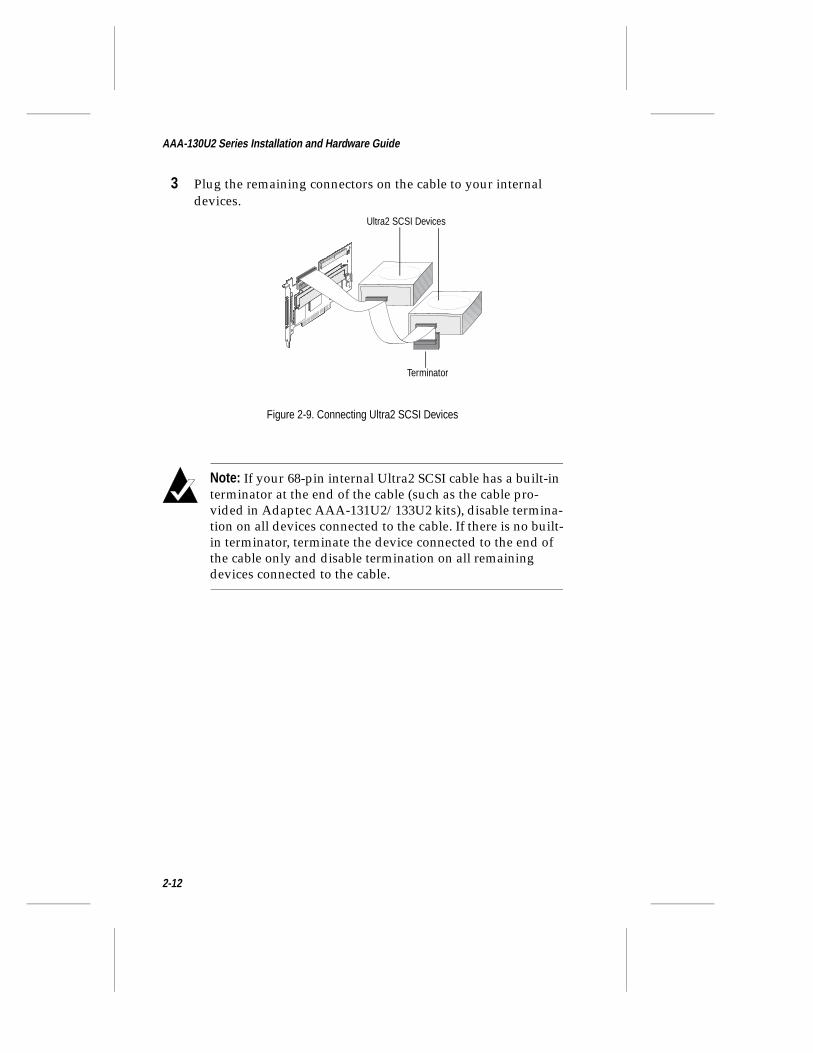
3 Plug the remaining connectors on the cable to your internal devices.
Note: If your 68-pin internal Ultra2 SCSI cable has a built-in terminator at the end of the cable (such as the cable pro-vided in Adaptec AAA-131U2/133U2 kits), disable termina-tion on all devices connected to the cable. If there is no built-in terminator, terminate the device connected to the end of the cable only and disable termination on all remaining devices connected to the cable.
Figure 2-9. Connecting Ultra2 SCSI Devices
Ultra2 SCSI Devices
Terminator
2-12
Installing the Hardware
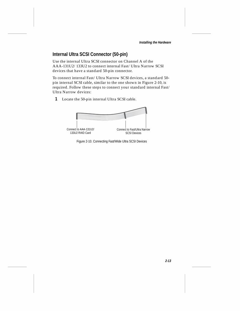
Internal Ultra SCSI Connector (50-pin)Use the internal Ultra SCSI connector on Channel A of the AAA-131U2/133U2 to connect internal Fast/Ultra Narrow SCSI devices that have a standard 50-pin connector.
To connect internal Fast/Ultra Narrow SCSI devices, a standard 50-pin internal SCSI cable, similar to the one shown in Figure 2-10, is required. Follow these steps to connect your standard internal Fast/Ultra Narrow devices:
1 Locate the 50-pin internal Ultra SCSI cable.
Figure 2-10. Connecting Fast/Wide Ultra SCSI Devices
Connect to Fast/Ultra NarrowSCSI Devices
Connect to AAA-131U2/133U2 RAID Card
2-13
AAA-130U2 Series Installation and Hardware Guide
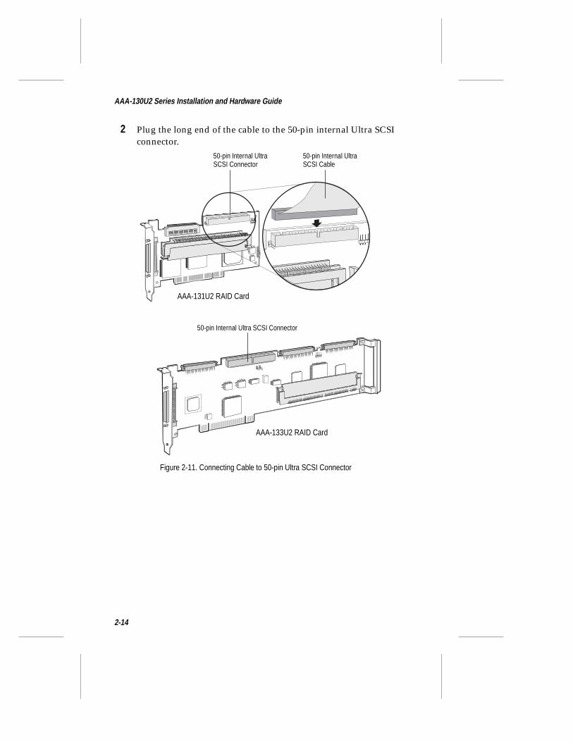
2 Plug the long end of the cable to the 50-pin internal Ultra SCSI connector.
50-pin Internal Ultra SCSI Connector
50-pin Internal UltraSCSI Connector
50-pin Internal Ultra SCSI Cable
AAA-131U2 RAID Card
AAA-133U2 RAID Card
Figure 2-11. Connecting Cable to 50-pin Ultra SCSI Connector
2-14
Installing the Hardware
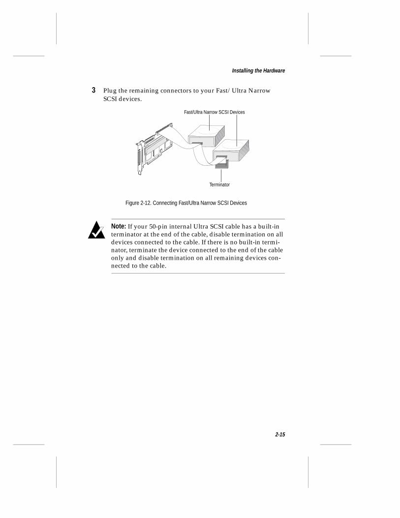
3 Plug the remaining connectors to your Fast/Ultra Narrow SCSI devices.
Note: If your 50-pin internal Ultra SCSI cable has a built-in terminator at the end of the cable, disable termination on all devices connected to the cable. If there is no built-in termi-nator, terminate the device connected to the end of the cable only and disable termination on all remaining devices con-nected to the cable.
Figure 2-12. Connecting Fast/Ultra Narrow SCSI Devices
Fast/Ultra Narrow SCSI Devices
Terminator
2-15
AAA-130U2 Series Installation and Hardware Guide
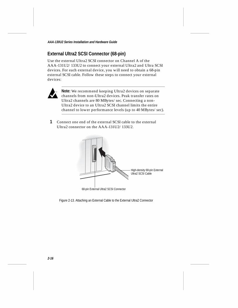
External Ultra2 SCSI Connector (68-pin)Use the external Ultra2 SCSI connector on Channel A of the AAA-131U2/133U2 to connect your external Ultra2 and Ultra SCSI devices. For each external device, you will need to obtain a 68-pin external SCSI cable. Follow these steps to connect your external devices:
Note: We recommend keeping Ultra2 devices on separate channels from non-Ultra2 devices. Peak transfer rates on Ultra2 channels are 80 MBytes/sec. Connecting a non-Ultra2 device to an Ultra2 SCSI channel limits the entire channel to lower performance levels (up to 40 MBytes/sec).
1 Connect one end of the external SCSI cable to the external Ultra2 connector on the AAA-131U2/133U2.
Figure 2-13. Attaching an External Cable to the External Ultra2 Connector
High-density 68-pin External Ultra2 SCSI Cable
68-pin External Ultra2 SCSI Connector
2-16
Installing the Hardware
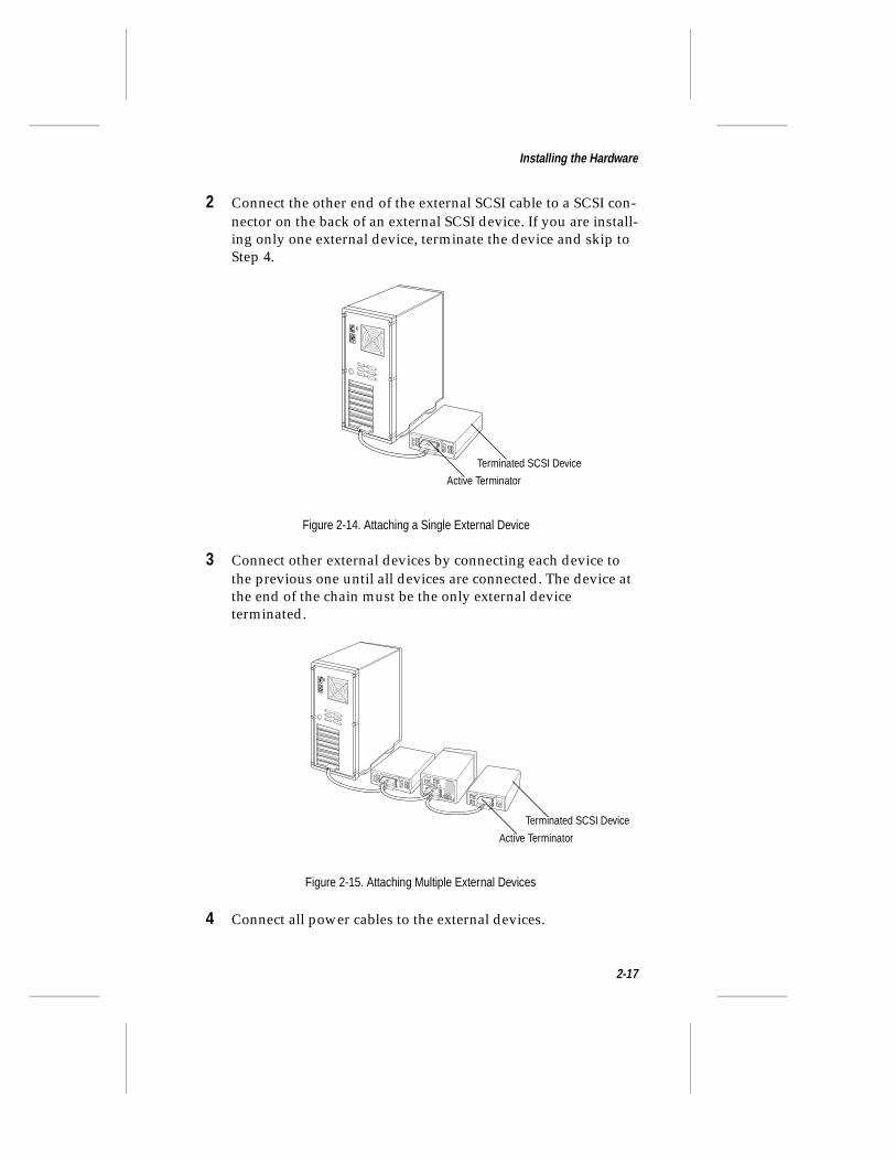
2 Connect the other end of the external SCSI cable to a SCSI con-nector on the back of an external SCSI device. If you are install-ing only one external device, terminate the device and skip to Step 4.
3 Connect other external devices by connecting each device to the previous one until all devices are connected. The device at the end of the chain must be the only external device terminated.
4 Connect all power cables to the external devices.
Figure 2-14. Attaching a Single External Device
3
Terminated SCSI Device
Active Terminator
3
2
4
Figure 2-15. Attaching Multiple External Devices
Terminated SCSI Device
Active Terminator
2-17
AAA-130U2 Series Installation and Hardware Guide
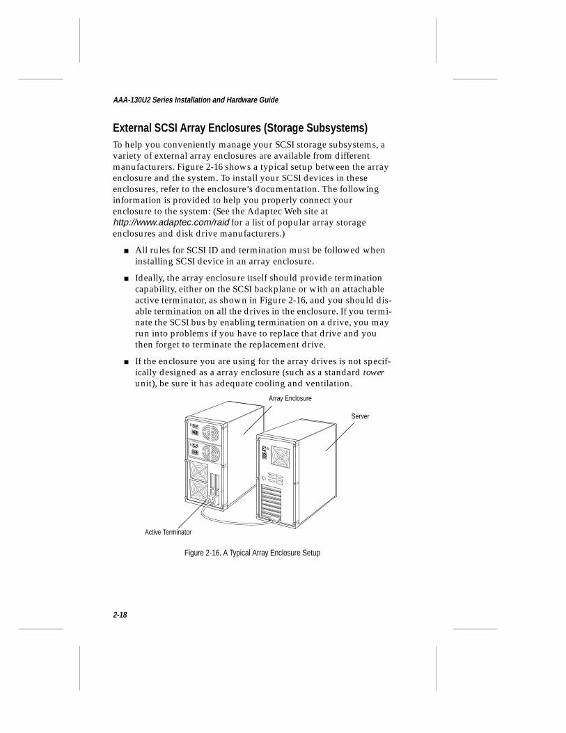
External SCSI Array Enclosures (Storage Subsystems)To help you conveniently manage your SCSI storage subsystems, a variety of external array enclosures are available from different manufacturers. Figure 2-16 shows a typical setup between the array enclosure and the system. To install your SCSI devices in these enclosures, refer to the enclosure’s documentation. The following information is provided to help you properly connect your enclosure to the system: (See the Adaptec Web site at http://www.adaptec.com/raid for a list of popular array storage enclosures and disk drive manufacturers.)
■ All rules for SCSI ID and termination must be followed when installing SCSI device in an array enclosure.
■ Ideally, the array enclosure itself should provide termination capability, either on the SCSI backplane or with an attachable active terminator, as shown in Figure 2-16, and you should dis-able termination on all the drives in the enclosure. If you termi-nate the SCSI bus by enabling termination on a drive, you may run into problems if you have to replace that drive and you then forget to terminate the replacement drive.
■ If the enclosure you are using for the array drives is not specif-ically designed as a array enclosure (such as a standard tower unit), be sure it has adequate cooling and ventilation.
Figure 2-16. A Typical Array Enclosure Setup
Active Terminator
Array Enclosure
Server
2-18
Installing the Hardware
Configuring the AAA-131U2/133U2After connecting all devices, reinstall the computer cover and con-nect all power cables. Turn on the external SCSI devices first, and then turn on the computer. During BIOS initialization, the AAA-131U2/133U2 BIOS banner should appear on the screen, and each device connected to the adapter should be listed. If the BIOS banner does not appear, see Appendix B, Troubleshooting.
Before installing the drivers and software for the AAA-131U2/133U2 RAID card, you may want to configure SCSI options (e.g., ID, Parity Checking, and Termination) for the card and the SCSI devices connected to it by running the onboard SCSISelect utility. To do this press F6 when the following prompt appears during BIOS initialization:
Press <F6> for SCSISelect (TM) Utility!
In most cases, it is not necessary to run the SCSISelect utility. Should you need to configure SCSI options, see Appendix A, Using SCSISelect and Disk Utilities for additional information.
❒
2-19

ê▼ ▼ ▼ ▼
Creating an Array With the ARRAYCONFIG U2 UtilityIn this Chapter
This chapter explains how to use the ARRAYCONFIG U2 Utility to create a bootable or non-bootable array on your system. If you want a bootable array on your system, you must use the ARRAYCONFIG U2 utility to create the bootable array.
Note: ARRAYCONFIG U2 runs from a self-booting diskette. If you are changing the configuration of a system that is already in use on a network, log all users off the system and shut it down in an orderly manner before you start ARRAYCONFIG U2.
Once the array is created, use Adaptec CI/O Management Software, which is included with the AAA-131U2/133U2, to create additional arrays (CI/O is required for array management in order to provide the proper level of fault tolerance and event notification). Refer to the Adaptec CI/O Management Software User’s Guide for instructions on installing and using the software.
➤ Creating an Array 3-2
➤ Making the Array Bootable 3-8
3-1
AAA-130U2 Series Installation and Hardware Guide
Caution: It is strongly recommended that you consistently and regularly backup your data to a backup media such as tape so you may recover your data due to failure events not protected by a fault tolerant array.
Creating an ArrayBefore creating the array, make sure the disks for the array are con-nected and installed in your system (or array enclosure). You can use ARRAYCONFIG U2 in two ways:
■ Select Express Setup if you want to create an array quickly and easily. ARRAYCONFIG U2 asks you a few simple questions and uses your answers to create the kind of array that best meets your needs.
■ Select Custom Setup if you want to perform advanced opera-tions, such as creating an array with specified disks or adding spare disks to an array being created.
Creating an Array with Express SetupFollow these steps to create an array with Express Setup. (You can probably complete the Express Setup process simply by following the instructions that appear on the screen.)
Note: To select ARRAYCONFIG U2 menu options, type the hot key—the letter that appears in a different color. (The hot key letters are underlined in the following instructions). You can also press the ↑ and ↓ keys until the option is high-lighted and then press Enter.
1 Insert the ARRAYCONFIG U2 diskette in drive A and reboot the system. Wait for ARRAYCONFIG U2 to start automatically.
2 Read the text that appears on the initial screens. Press any key to view the next screen, or press Esc to return to the previous screen.
3 Select Express Setup from the Setup Type Selection menu.
3-2
Creating an Array With the ARRAYCONFIG U2 Utility
4 When the next screen appears, select the type of array you want to create:
– Select Optimized for Performance (RAID 0) if you want the fastest possible data input and output from the new array. This kind of array does not have special data protec-tion features, however. When prompted, type the number of disks you want in this array.
– Select Optimized for Data Protection (RAID 1) if your main concern is to protect the files on the array from disk failure. This kind of array safeguards files in the array even if one of the array disks fails. (This kind of array has two disks by definition, so you will not be prompted to enter the number of disks you want in the array.)
– Select Performance and Data Protection with Parity (RAID 5) if you want fast performance and data protection, and you have three or more disks available for the array. This kind of array contains redundant (parity) data distrib-uted across all disks in the array. If any one disk fails, data can be reconstructed from the parity information. If a second disk fails before the array has been reconstructed, all data is lost. The actual usable data capacity of the array is equal to one less than the total number of disks. (One disk’s worth of capacity is needed to hold the parity information.)
– Select Performance and Data Protection with Mirroring (RAID 0/1) if you want fast performance and data protec-tion, and have an even number of disks available for the array. This kind of array stripes and mirrors data on two or more pairs of disks. If one disk in a pair fails, data is avail-able. The actual data capacity of the array equals half the total available disk space.
5 When the next menu appears, select the type of applications that you will run on your system. (Select Others if you are not sure what type of applications you will use.) ARRAYCONFIG U2 will use your answer to create the best array configuration for your applications.
3-3
AAA-130U2 Series Installation and Hardware Guide
6 When the next menu appears, select a boot order for the new array.
– Select Disk Array will be Boot Drive if you want your sys-tem to boot from the new array. If you selected Optimized for Data Protection in Step 4, booting from an array safe-guards the information on your boot drive. (To boot from an array, you must also install the operating system soft-ware on the array, as described in later chapters.)
– Select Disk Array will not be a Boot Drive if you do not want your system to boot from the new array.
7 When you have finished all these menu selections, wait while ARRAYCONFIG U2 creates the array. This may take a long time, especially if the drives are large in capacity.
A message appears when the array has been created. An error message appears if fewer than two drives are available or if ARRAYCONFIG U2 encounters some other problem. If this happens, install more drives or run ARRAYCONFIG U2 again and use the Custom Setup option.
8 When the array is created, exit ARRAYCONFIG U2, remove the ARRAYCONFIG U2 diskette, and reboot the system. After you reboot you can write data to the array.
Creating an Array with Custom SetupFollow these instructions to create an array with ARRAYCONFIG U2:
1 Insert the ARRAYCONFIG U2 diskette in drive A and reboot the system. Wait for ARRAYCONFIG U2 to start automatically.
2 Read the text that appears on the initial screens. Press any key to view the next screen, or press ESC to return to the previous screen.
3 Select Custom Setup from the Setup Type Selection Menu.
4 Select Disk Array Operations from the Main Menu.
5 Select Create New Array from the Disk Array Operations menu.
3-4
Creating an Array With the ARRAYCONFIG U2 Utility
6 Type an array name and press Enter. The name can be up to 15 characters long and can include spaces and any other printable characters.
7 Select an array type. Your options are
– RAID 0: Data is striped across the disks in a RAID 0 array, allowing for faster I/O performance than a single disk. RAID 0 arrays do not store redundant data; if any disk in the array fails, all data is lost.
– RAID 1: Data is mirrored on one pair of disks. If one disk fails, data is available. The actual data capacity of the array equals half the available disk space.
– RAID 5: The array contains redundant (parity) data dis-tributed across all disks in the array. If any one disk fails, data can be reconstructed from the parity information. If a second disk fails before the array has been reconstructed, all data is lost. The actual usable data capacity of the array is equal to one less than the total number of disks. (One disk’s worth of capacity is needed to hold the parity information.)
– RAID 0/1: Data is striped and mirrored on two or more pairs of disks. If one disk in a pair fails, data is available. The actual data capacity of the array equals half the total available disk space.
See the Adaptec CI/O Management Software User’s Guide for more information on selecting a RAID level.
8 Select the number of drives you want in the array and press Enter. This number should not include spares (drives that auto-matically replace failed array drives). The number of drives available for assignment is listed on the screen.
Note: This step does not apply to RAID 1 arrays, which have two drives by definition.
3-5
AAA-130U2 Series Installation and Hardware Guide
9 Select array members. When the next screen appears, press Tab to highlight a channel (if more than one SCSI channel is avail-able). Select drives for the array by pressing the ↑ and ↓ keys until the drive name is highlighted, and then press Ins or Enter. The names of selected drives appear in the Adaptec Array # box.
To select drives on a different channel press Tab to select another channel and then select the drives from the SCSI IDs on the Channel menu. To deselect the drive you most recently added, press Del.
Caution: A warning appears if you select a disk that has partitions. Do not select a partitioned disk if it con-tains data you want to keep, because any existing data will be erased when the disk becomes part of an array.
When you have selected the number of drives you specified in Step 8, the next screen appears automatically. If you are creat-ing a RAID 1, RAID 0/1, or RAID 5 array, and if there are any unassigned drives, the screen prompts you to define dedicated spare drives for the array. (We recommend that you use a spare pool instead of dedicated spares.)
Note: A spare must have at least the capacity of the smallest drive in the array.
10 Select spares. If you do not want a spare, type n and continue with Step 12. If you want to select dedicated spares, follow these steps:
a At the prompt, type y.
b At the next prompt, type 1 or 2.
c Select one or two spares, using the same method you used to select disks for the array.
3-6
Creating an Array With the ARRAYCONFIG U2 Utility
11 Initialize array. When the Initialize Mode menu appears, select Initialize Array to Zero. A graph on the screen shows the progress of this operation.
Caution: If the drives contain data, all the data is lost when you initialize the array.
Select Low-Level Format only if the drives were previously formatted on another computer or if you think they may have surface defects. Low-level formatting takes a long time for large capacity disk drives.
12 Select array block size. When the menu of block sizes appears, select a block size. (This menu does not appear if the array is a mirrored array with only two drives.)
The allowable block sizes are 8, 16, 32, 64 (the default), and 128 KBytes. The default block size gives the best overall performance in most environments.
13 Wait for initialization to complete. When you see the message Initialization of [array name] is complete, press any key to return to the Disk Array Operations menu.
14 Create additional arrays. You may use ARRAYCONFIG U2 to create additional arrays (if disks are available), however we recommend using Adaptec CI/O Management Software to create additional arrays. (CI/O is required for array manage-ment in order to provide the proper level of fault tolerance and event notification.) See the Adaptec CI/O Management Software User’s Guide for more information.
15 When all arrays are created, exit ARRAYCONFIG U2, remove the ARRAYCONFIG U2 diskette, and reboot the system. After you reboot you can write data to the arrays. At this point, you can make the array bootable as described in the next section.
3-7
AAA-130U2 Series Installation and Hardware Guide
Making the Array BootableYou can make the array bootable so that the system boots from the array instead of from a stand-alone (single) disk.
To make the array bootable, the array must be set to #0 in the boot order. Follow these steps if you want the system to boot from the newly created array:
Note: The system will always attempt to boot from any installed non-SCSI hard disks (for example, any IDE hard disk at drive C). You must disable or remove all non-SCSI hard disks if you want the system to boot from a SCSI hard disk or array.
1 Insert the ARRAYCONFIG U2 disk in drive A and reboot the system. Wait for ARRAYCONFIG U2 to start automatically.
2 Read the text that appears on the initial screens. Press any key to view the next screen, or press ESC to return to the previous screen.
3 Select Custom Setup from the Setup Type Selection Menu.
4 Select Display Boot Order from the Main Menu. The Boot Order for Singles and Arrays window appears.
5 If the newly created array is at the top of the list, preceded by the words Unit 0, no changes are necessary; if it has some other unit number, highlight the array name and press Enter.
6 Use the arrow keys to move the selected array to the top of the list. Then press Enter. If you want to change the boot order of another array, select it, move it with the arrow keys, and press Enter again.
7 Press Esc to return to the Main Menu.
8 Exit ARRAYCONFIG U2, remove the disk from drive A, and reboot the system.
3-8
Creating an Array With the ARRAYCONFIG U2 Utility
9 Prepare the array as you normally would prepare a boot disk drive for your operating system. See either Chapter 4, Installing the Software Driver for Windows NT, Chapter 5, Installing the Software Driver for Novell NetWare, or Chapter 6, Installing the Software Driver for SCO UnixWare.
Note: You cannot use this procedure to change the boot order of a SCSI disk drive that is not part of an array. If you want to do this, create a one-disk RAID 0 array from the disk. (Data is not actually striped on a one-disk array.)
❒
3-9

é▼ ▼ ▼ ▼
Installing the Software Driver for Windows NTIn this Chapter
This chapter explains how to install the AAA-131U2/133U2 soft-ware driver (cda1000.sys) for Windows NT (Windows NT 4.0 Server and Workstation). Before installing the driver, make sure you have completed the following:
■ Installed the AAA-131U2/133U2 in your system. (See Chapter 2)
■ Created the first array using the ARRAYCONFIG U2 utility, if you plan to boot from an array. (See Chapter 3)
Once Windows NT and the driver are installed, install Adaptec CI/O Management Software and use it to add, delete, and manage arrays from the server console (CI/O is required for array management in order to provide the proper level of fault tolerance and event notification). Refer to the Adaptec CI/O Management Software User’s Guide for instructions on installing and using the software.
➤ Installing the Array1000U2 Driver for Windows NT 4-2
➤ Windows NT Installation and Configuration Notes 4-5
4-1
AAA-130U2 Series Installation and Hardware Guide
Installing the Array1000U2 Driver for Windows NTTo begin driver installation, see either Installing the Driver When Install-ing Windows NT on page 4-2, or Installing the Driver When Windows NT is Already Installed on page 4-4.
Note: We recommend that you install your Windows NT operating system on a fault-tolerant array (RAID 5, 1, or 0/1) to take advantage of the redundancy and performance features of the array.
Installing the Driver When Installing Windows NTTo install the cda1000.sys driver when you are installing Windows NT, follow these steps:
Note: During Windows NT installation, if your system configuration has multiple arrays and/or single drives, Windows NT limits the size of the system partition you can create to 1 GByte. To work around this 1 GByte limitation, see Windows NT 1 GByte Partition Limitation on page 4-5.
1 Start your system with the Windows NT Boot disk in the floppy disk drive or the Windows NT Boot CD-ROM in the CD-ROM drive.
Note: When using a SCSI CD-ROM drive to install Windows NT from the bootable CD-ROM, make sure BIOS Support for Bootable CD-ROM is enabled in SCSISelect.
4-2
Installing the Software Driver for Windows NT
2 Windows NT Boot disk installation: When prompted, insert disk #2 in your floppy drive. After a few moments you will see a blue screen. To setup Windows NT now, press Enter and con-tinue with Step 3 below.
Windows NT Boot CD-ROM installation: When the following message appears onscreen, press the F6 key and skip to Step 4 below.
Setup is inspecting your computer system’s hardware…
3 Press S to skip autodetection of your SCSI host adapter.
4 Press S again to specify an additional device.
5 Press Enter to select Others; insert the Adaptec Array1000U2 Family Manager Set driver disk in your floppy disk drive and press Enter.
6 The screen displays the adapter drivers supported on the disk. Select the Adaptec Array1000U2 Family Adapter driver and press Enter.
7 If you want to add drivers (other than for the AAA-131U2/133U2), press S and repeat Step 5 for each additional adapter and insert the appropriate disk provided by the hardware manufacturer.
8 Press Enter to continue with the Windows NT operating system setup. Follow the instructions onscreen and in the Windows NT documentation to complete the installation.
9 When Windows NT installation is complete, install Adaptec CI/O Management Software. Refer to the Adaptec CI/O Man-agement Software User’s Guide for instructions on installing and using the software.
4-3
AAA-130U2 Series Installation and Hardware Guide
Installing the Driver When Windows NT is Already InstalledTo update or install the cda1000.sys driver if Windows NT is already installed, follow these steps:
1 Start Windows NT.
2 Click the Start button on the Windows NT task bar, and then point to Settings.
3 Click the Control Panel.
4 Double-click the SCSI Adapters icon.
5 Click the Drivers tab, and then click the Add button.
6 In the Install Driver window, click the Have Disk button.
7 Insert the Adaptec Array1000U2 Family Manager Set driver disk in your floppy disk drive and press Enter. Enter the fol-lowing path to the installation files and then click OK.
a:\winnt
The Adaptec Array1000U2 Family Adapter driver is high-lighted by default.
8 In the Install Driver window, Click OK.
9 You must restart your computer for the changes to take effect. Click Yes to restart your computer.
10 When driver installation is complete, install Adaptec CI/O Management Software. Refer to the Adaptec CI/O Management Software User’s Guide for instructions on installing and using the software.
4-4
Installing the Software Driver for Windows NT
Windows NT Installation and Configuration Notes
Windows NT 1 GByte Partition LimitationDuring Windows NT installation, if your system configuration has multiple arrays and/or single drives, Windows NT limits the size of the system partition you can create to 1 GByte. To work around this 1 GByte limitation, try the following:
■ During Windows NT installation, create the 1 GByte partition (do not finish setup); reboot the system and then delete the partition. This allows Windows NT Setup to create a system partition larger than 1 GByte, but limited to 4 GBytes or 1024 cylinders of data, whichever is less.
or
■ Using MS-DOS, create a partition using fdisk. During Windows NT installation, delete the partition created with MS-DOS. This allows Windows NT Setup to create a system partition larger than 1 GByte, but limited to 4 GBytes or 1024 cylinders of data, whichever is less.
If Windows NT Setup HangsDuring Windows NT installation, the system may hang while the Windows NT Setup floppy disk is being used to copy the SCSI disk device driver. A workaround is to boot from a DOS boot disk, create a DOS partition on the array using fdisk, and then install Windows NT on the array.
Windows NT Disk AdministratorWhen creating a new array on a system running under Windows NT, the array is not listed as “usable” in the NT Disk Administrator until it is initialized. This is normal Windows NT functionality.
4-5
AAA-130U2 Series Installation and Hardware Guide
Boot Order In Windows NT vs. ARRAYCONFIG U2During Windows NT installation, Windows NT does not show the devices in the boot order. Instead, it shows the arrays with the lower SCSI ID (on lower channel) first. To minimize confusion during Windows NT installation, try one of the following:
■ Disconnect all devices other than members of the boot array, so that only one logical device is present in the Windows NT installation. Reconnect all other devices after Windows NT is successfully installed.
■ Configure the boot array in the ARRAYCONFIG U2 utility so that the lowest SCSI ID on the lowest channel is a member of the boot array.
Microsoft BackOffice Small Business ServerMicrosoft BackOffice Small Business Server features a non-bootable installation CD and setup boot disks which do not ask for a third-party driver disk. (Manufacturer-supplied hardware support disks.) To have the installation program prompt you for the third-party driver disk, do the following:
1 Copy the winnt.sif file from the I386 directory on the BackOffice Small Business Server CD to Disk 2 of the setup boot disks (overwrite existing file).
2 Boot the system using the setup boot disks. Press <F6> while the message “Setup is inspecting your computer system’s hard-ware...” is displayed.
3 You will be prompted for the driver disk during the installation process.
❒
4-6
è▼ ▼ ▼ ▼
Installing the Software Driver for Novell NetWareIn this Chapter
This chapter explains how to install the AAA-131U2/133U2 soft-ware driver (cda1000h.ham) for Novell NetWare (NetWare 4.11, 4.2, and 5.0). Before installing the driver, make sure you have completed the following:
■ Installed the AAA-131U2/133U2 in your system (See Chapter 2)
■ Created the first array using the ARRAYCONFIG U2 utility, if you plan to boot from an array. (See Chapter 3)
Once NetWare and the driver are installed, install Adaptec CI/O Management Software from the server console (CI/O is required for array management in order to provide the proper level of fault tolerance and event notification). Refer to the Adaptec CI/O Manage-ment Software User’s Guide for instructions on installing and using the software.
➤ Installing the Array1000U2 Driver for Novell NetWare 5-2
➤ Netware Installation and Configuration Notes 5-8
5-1
AAA-130U2 Series Installation and Hardware Guide
Installing the Array1000U2 Driver for Novell NetWareTo begin driver installation, see either Installing the Driver When Installing NetWare on page 5-2, or Installing the Driver When NetWare is Already Installed on page 5-7.
Note: We recommend that you install your Novell NetWare operating system on a fault-tolerant array (RAID 5, 1, or 0/1) to take advantage of the redundancy and performance features of the array.
Installing the Driver When Installing NetWareTo install the cda1000h.ham driver when you are installing NetWare, follow the instructions below for the version of NetWare you are installing.
Note: The instructions below assume your CD-ROM is connected to the AAA-131U2/133U2. If your CD-ROM is not connected to the AAA-131U2/133U2 (for example, con-nected to an IDE controller), you will need to include com-mand lines in the config.sys and autoexec.bat files similar to those described below. Refer to the documentation for the adapter the CD-ROM is connected for the appropriate command lines.
NetWare 4.11 and 4.2Follow these instructions only if you are installing NetWare 4.11 or 4.2 for the first time:
1 Create a DOS partition and install DOS on your system.
2 Copy the aspi8u2.sys and aspicd.sys files from the \dos direc-tory on the Adaptec Array1000U2 Family Manager Set driver disk to a directory (e.g., c:\scsi) on your hard disk.
5-2
Installing the Software Driver for Novell NetWare
3 Edit the config.sys file to include command lines for aspi8u2.sys and aspicd.sys. The following sample command lines for the config.sys file are appropriate for most systems:
device=c:\scsi\aspi8u2.sys /ddevice=c:\scsi\aspicd.sys /d:aspicd0
Note: For non-Ultra2 systems, use aspi8dos.sys instead of aspi8u2.sys in the command line (for exam-ple, device=c:\scsi\aspi8dos.sys /d).
4 Edit the autoexec.bat file to include a command line for mscdex.exe (the mscdex.exe file is included with MS-DOS 6.x and above). The following sample command lines for the autoexec.bat file are appropriate for most systems:
c:\dos\mscdex.exe /d:aspicd0 /M:12
(This assigns the CD-ROM the next available drive letter, typi-cally D if there is only one DOS drive.)
5 Reboot the system to the DOS partition.
6 Insert the NetWare CD in your CD-ROM drive.
7 Go to the CD-ROM drive.
8 Type Install and press Enter.
9 Follow the procedures in your NetWare documentation for installing a new server.
10 If prompted to load an SMP Module, select No. (The SMP Module can be installed once NetWare is up and running.)
11 When a screen appears that asks you to select a disk driver, press Enter.
12 Press Insert to install an unlisted driver.
13 Insert the Adaptec Array1000U2 Family Manager Set driver disk into your floppy disk drive.
14 Press F3 and specify the path to the cda1000h.ham driver. For NetWare 4.1, the driver is located in \netware\v4_1x on the disk. For NetWare 4.2, the driver is located in \netware.
5-3
AAA-130U2 Series Installation and Hardware Guide
15 Select cda1000h.ham and press Enter.
16 When prompted to save existing file c:\nwserver\nbi.nlm, select No.
17 When prompted to save existing file c:\nwserver\nwpaload.nlm, select No.
18 When prompted to save existing file c:\nwserver\nwpa.nlm, select No.
19 When prompted, select Select/Modify driver parameters.
20 Enter a valid slot number, then press Enter to save field data.
21 Press F10 to save parameter settings.
22 When prompted, select Save parameters and continue.
23 Select No when prompted to select an additional disk driver.
24 Select Continue Installation.
25 When NetWare installation is complete, install Adaptec CI/O Management Software from the server console. Refer to the Adaptec CI/O Management Software User’s Guide for instructions on installing and using the software.
Note: To load the driver automatically at server bootup, make sure the startup.ncf file includes the load command line for the cda1000h.ham driver. (If you also have an Adaptec host adapter that uses the Adaptec aic78xx.dsk driver, make sure the driver loads after the cda1000h.ham driver.)
5-4

Installing the Software Driver for Novell NetWare
Note: Older versions of the aic78xx.dsk driver (before v1.30) are compatible with cda1000h.ham as long as the AAA-131U2/133U2 PCI slot is not specified on the com-mand line (e.g., load aic7870.dsk slot=z). If there is an AIC-78xx based card (e.g., AHA™-2940) in the system, z must point to that card’s slot number and not to the AAA-131U2/133U2 slot number. If loaded without com-mand line parameters, NetWare lists valid slot numbers. The AAA-131U2/133U2 will be listed in the parameter list; however, do not select it.
NetWare 5.0Follow these instructions only if you are installing NetWare 5.0 for the first time:
1 Create a DOS partition and install DOS on your.
2 Copy the aspi8u2.sys and aspicd.sys files from the \dos direc-tory on the Adaptec Array1000U2 Family Manager Set driver disk to a directory (e.g., c:\scsi) on your hard disk.
3 When using a SCSI CD-ROM, edit the config.sys file to include command lines for aspi8u2.sys and aspicd.sys. The following sample command lines for the config.sys file are appropriate for most systems:
device=c:\scsi\aspi8u2.sys /ddevice=c:\scsi\aspicd.sys /d:aspicd0
Note: For non-Ultra2 systems, use aspi8dos.sys instead of aspi8u2.sys in the command line (for exam-ple, device=c:\scsi\aspi8dos.sys /d).
5-5

AAA-130U2 Series Installation and Hardware Guide
4 Edit the autoexec.bat file to include a command line for mscdex.exe (the mscdex.exe file is included with MS-DOS 6.x and above). The following sample command lines for the autoexec.bat file are appropriate for most systems:
c:\dos\mscdex.exe /d:aspicd0 /M:12
(This assigns the CD-ROM the next available drive letter, typi-cally D if there is only one DOS drive.)
5 Reboot the system to the DOS partition.
6 Insert the NetWare 5.0 CD in your CD-ROM drive.
7 Go to the CD-ROM drive.
8 Type Install and press Enter.
9 Follow the procedures in your NetWare documentation for installing a new server.
10 From the Welcome to the NetWare server installation screen, press F2 for Advanced Settings; change Load server at reboot: from Yes to No and continue with the installation.
11 When NetWare detects device drivers for the server, you are prompted to Add, Change, or Delete drivers as needed:
– Delete any Multiple Processor Support module that is detected (for example, MPS14).
– Delete the Storage Adapters drivers for adapters that are not present in your system.
12 Insert the Adaptec Array1000U2 Family Manager Set driver disk in your floppy disk drive.
13 Select Storage Adapters and press Enter.
14 To add Storage Adapter driver, press Insert.
15 Press Insert again to add an unlisted driver.
16 Press F3 to specify a different path. Enter the following path:
a:\netware
17 Select Return to Driver Summary and press Enter. CDA1000 is listed as your storage adapter.
5-6
Installing the Software Driver for Novell NetWare
18 Remove the disk from your floppy disk drive.
19 Select Continue.
20 Follow the procedures in your NetWare documentation to complete the installation.
21 When installation is complete, restart the system.
22 At the DOS prompt (c:\), change to the c:\nwserver directory and enter
server
23 At this point, install Adaptec CI/O Management Software from the server console. Refer to the Adaptec CI/O Management Software User’s Guide for instructions on installing and using the software.
Installing the Driver When NetWare is Already InstalledTo update or install the cda1000h.ham driver if NetWare is already installed, follow the instructions below for the version of NetWare you have installed.
NetWare 4.11 and 4.2
1 Copy the cda1000h.ham file from the Adaptec Array1000U2 Family Manager Set driver disk into the server’s startup direc-tory (e.g., c:\nwserver) on your hard disk.
Note: For NetWare 4.11, the cda1000h.ham file is in a:\netware\v4_1x. For NetWare 4.2, the cda1000h.ham file is in a:\netware.
2 If necessary, modify the load command line in the startup.ncf so that the proper path to the driver is specified. The correct syntax to load the cda1000h.ham driver is
load [pathname]cda1000
5-7
AAA-130U2 Series Installation and Hardware Guide
NetWare 5.0
1 Copy the cda1000h.ham file from the Adaptec Array1000U2 Family Manager Set driver disk into the server’s startup direc-tory (e.g., c:\nwserver) on your hard disk.
Note: For NetWare 5.0, the cda1000h.ham file is in a:\netware.
2 If necessary, modify the load command line in the startup.ncf so that the proper path to the driver is specified. The correct syntax to load the cda1000h.ham driver is
load [pathname]cda1000
Netware Installation and Configuration Notes
Larger Than 4 GByte Arrays When installing NetWare on an array 4 GBytes or larger, the Install program erroneously reports that the DOS partition is too small. It, however, does allow you to continue installation. Ignore this error message.
Unloading cda1000h.hamWhen running Adaptec CI/O Management Software, do not unload cda1000h.ham while iomgr.nlm is still loaded. Unstable behavior may result.
❒
5-8
ç▼ ▼ ▼ ▼
Installing the Software Driver for SCO UnixWareIn this Chapter
This chapter explains how to install the AAA-131U2/133U2 soft-ware driver (cda1000) for SCO UnixWare 7.0. Before installing the driver, make sure you have completed the following:
■ Installed the AAA-131U2/133U2 in your system. (See Chapter 2)
■ Created the first array using the ARRAYCONFIG U2 utility, if you plan to boot from an array. (See Chapter 3)
Once UnixWare and the driver are installed, install Adaptec CI/O Management Software from the server’s X Window (CI/O is required for array management in order to provide the proper level of fault tolerance and event notification). Refer to the Adaptec CI/O Management Software User’s Guide for instructions on installing and using the software.
➤ Installing the Array1000U2 Driver for UnixWare 6-2
6-1
AAA-130U2 Series Installation and Hardware Guide
Installing the Array1000U2 Driver for UnixWareTo begin driver installation, see either Installing the Driver When Installing SCO UnixWare below, or Installing the Driver When SCO UnixWare is Already Installed on page 6-3.
Installing the Driver When Installing SCO UnixWareTo install the cda1000 driver at the same time you install SCO UnixWare, follow the instructions below:
1 Insert the SCO UnixWare Installation disk in the floppy boot drive. Reboot your computer.
Wait for the first SCO UnixWare installation screen and prompt to appear, then follow the onscreen instructions.
2 When prompted to Install HBA Diskette, first remove the Installation disk, then insert the Adaptec Array1000U2 Family Manager Set driver disk for SCO UnixWare into your floppy disk drive.
3 Select Install HBA Diskette and press F10.
4 If you have additional HBA disks, insert the next HBA disk, select Install HBA Diskette and press F10.
If all of your HBA disks have been installed, select Proceed With Installation and press F10. (Do not reinstall the cda1000 HBA disk.)
5 If necessary, enter the DCU (Device Configuration Utility) to view/change the SCO UnixWare device driver configuration data; otherwise select Continue With Installation.
6 When prompted, reinsert the HBA disk (Adaptec Array1000U2 Family Manager Set driver disk for SCO UnixWare) that you inserted in Step 3 above, and press Enter.
7 Follow the onscreen instructions to complete the installation.
Note: If your installation fails, do not attempt to use the update installation pkgadd procedure to fix the installation. Follow the instructions in the SCO UnixWare documenta-tion and in this document to retry the installation.
6-2
Installing the Software Driver for SCO UnixWare
8 When SCO UnixWare installation is complete, install Adaptec CI/O Management Software. Refer to the Adaptec CI/O Man-agement Software User’s Guide for instructions on installing and using the software.
Installing the Driver When SCO UnixWare is Already InstalledTo update or install the cda1000 driver on a system where SCO UnixWare is already installed, follow the instructions below:
1 At the system prompt, type the following and press Enter:
pkgadd -d diskette1
2 Follow the instructions onscreen to insert the HBA disk (the Adaptec Array1000U2 Family Manager Set driver disk for SCO UnixWare) into your floppy disk drive and press Enter.
3 When prompted to select packages, select all packages (press Return). The package is loaded into your SCO UnixWare oper-ating system.
4 When the package has loaded, you may be prompted to install the disk again. Do not reinsert the HBA disk (Adaptec Array1000U2 Family Manager Set driver disk for SCO UnixWare). Instead, type q (quit) and press Enter.
5 Shutdown or reboot the system.
6 When prompted to rebuild the kernel, select go.
7 When driver installation is complete, install Adaptec CI/O Management Software. Refer to the Adaptec CI/O Management Software User’s Guide for instructions on installing and using the software.
❒
6-3

$▼ ▼ ▼ ▼
Using SCSISelect and Disk UtilitiesIn this Appendix
The AAA-131U2/133U2 has the onboard SCSISelect configuration utility, which allows you to change SCSI options (e.g., ID, Parity Checking, and Termination) without opening the computer chassis or handling the card. This appendix describes the default settings, explains when you should change them, and gives instructions for doing so.
SCSISelect also includes SCSI disk utilities to list the SCSI IDs of devices connected to the AAA-131U2/133U2, format SCSI disk drives, and check SCSI disk drives for defects. Instructions for using these utilities are included.
➤ SCSISelect Default Settings A-2
➤ Starting the SCSISelect Utility A-3
➤ Using the SCSI Disk Utilities A-3
➤ SCSISelect Settings A-5
A-1
AAA-130U2 Series Installation and Hardware Guide
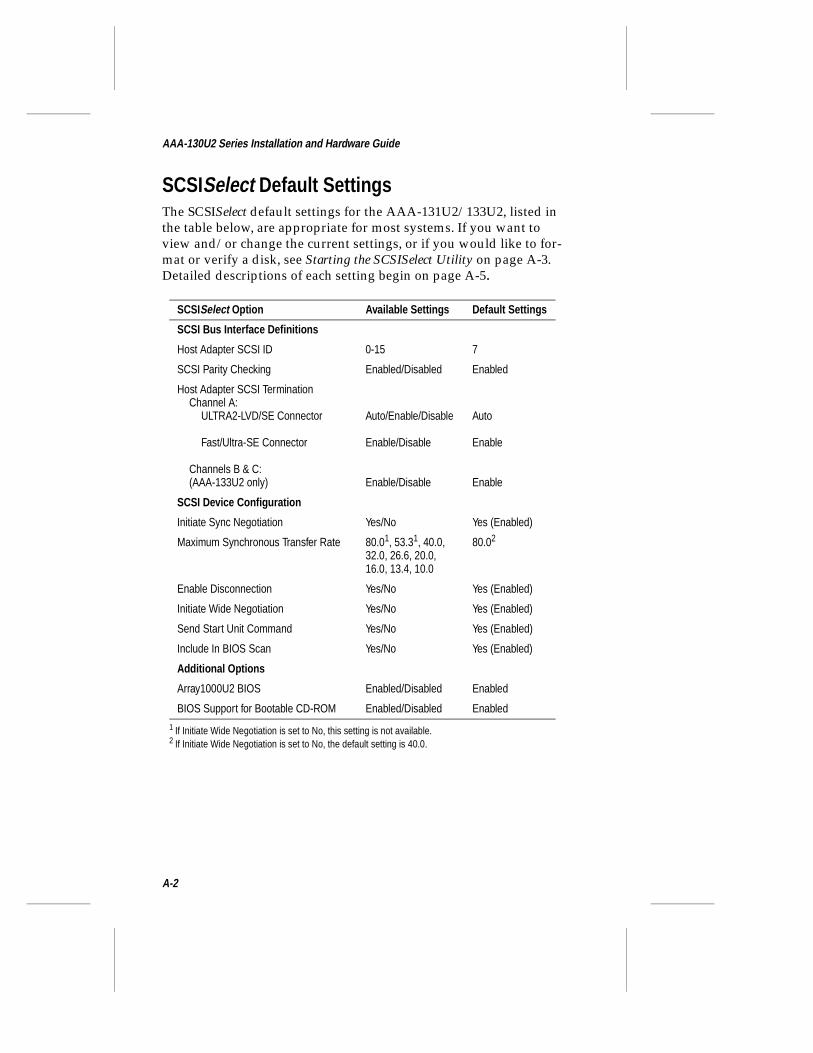
SCSISelect Default SettingsThe SCSISelect default settings for the AAA-131U2/133U2, listed in the table below, are appropriate for most systems. If you want to view and/or change the current settings, or if you would like to for-mat or verify a disk, see Starting the SCSISelect Utility on page A-3. Detailed descriptions of each setting begin on page A-5.
SCSISelect Option Available Settings Default Settings
SCSI Bus Interface Definitions
Host Adapter SCSI ID 0-15 7
SCSI Parity Checking Enabled/Disabled Enabled
Host Adapter SCSI TerminationChannel A:
ULTRA2-LVD/SE Connector
Fast/Ultra-SE Connector
Channels B & C:(AAA-133U2 only)
Auto/Enable/Disable
Enable/Disable
Enable/Disable
Auto
Enable
Enable
SCSI Device Configuration
Initiate Sync Negotiation Yes/No Yes (Enabled)
Maximum Synchronous Transfer Rate 80.01, 53.31, 40.0, 32.0, 26.6, 20.0, 16.0, 13.4, 10.0
1 If Initiate Wide Negotiation is set to No, this setting is not available.
80.02
2 If Initiate Wide Negotiation is set to No, the default setting is 40.0.
Enable Disconnection Yes/No Yes (Enabled)
Initiate Wide Negotiation Yes/No Yes (Enabled)
Send Start Unit Command Yes/No Yes (Enabled)
Include In BIOS Scan Yes/No Yes (Enabled)
Additional Options
Array1000U2 BIOS Enabled/Disabled Enabled
BIOS Support for Bootable CD-ROM Enabled/Disabled Enabled
A-2
Using SCSISelect and Disk Utilities
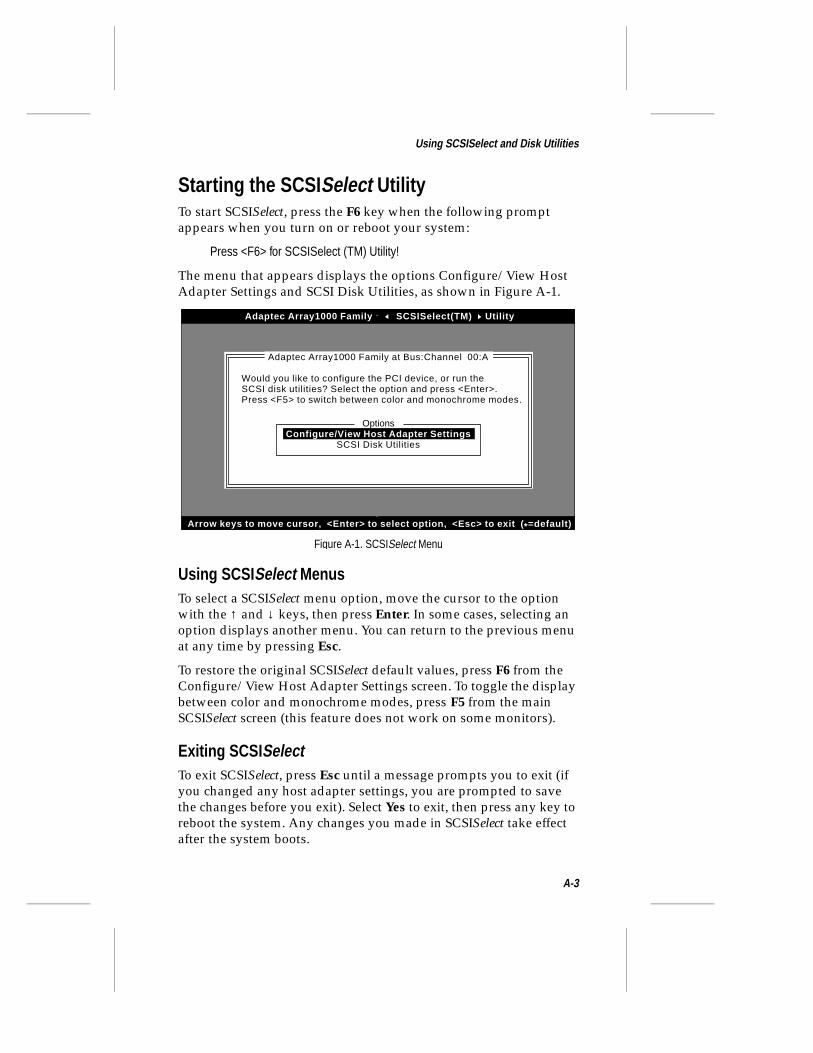
Starting the SCSI Select UtilityTo start SCSISelect, press the F6 key when the following prompt appears when you turn on or reboot your system:
Press <F6> for SCSISelect (TM) Utility!
The menu that appears displays the options Configure/View Host Adapter Settings and SCSI Disk Utilities, as shown in Figure A-1.
Using SCSI Select MenusTo select a SCSISelect menu option, move the cursor to the option with the ↑ and ↓ keys, then press Enter. In some cases, selecting an option displays another menu. You can return to the previous menu at any time by pressing Esc.
To restore the original SCSISelect default values, press F6 from the Configure/View Host Adapter Settings screen. To toggle the display between color and monochrome modes, press F5 from the main SCSISelect screen (this feature does not work on some monitors).
Exiting SCSI SelectTo exit SCSISelect, press Esc until a message prompts you to exit (if you changed any host adapter settings, you are prompted to save the changes before you exit). Select Yes to exit, then press any key to reboot the system. Any changes you made in SCSISelect take effect after the system boots.
Adaptec Array1000 Family SCSISelect(TM) Utility
Arrow keys to move cursor, <Enter> to select option, <Esc> to exit ( *=default)
Would you like to configure the PCI device, or run theSCSI disk utilities? Select the option and press <Enter>.Press <F5> to switch between color and monochrome modes.
Adaptec Array1000 Family at Bus:Channel 00:A
OptionsConfigure/View Host Adapter Settings
SCSI Disk Utilities
Figure A-1. SCSISelect Menu
A-3
AAA-130U2 Series Installation and Hardware Guide
Using the SCSI Disk UtilitiesTo access the SCSI disk utilities, select the SCSI Disk Utilities option from the menu that appears after starting SCSISelect. Once the option is selected, SCSISelect immediately scans the SCSI bus (to determine the devices installed) and displays a list of all SCSI IDs and the devices assigned to each ID.
When you select a specific ID and device, a small menu appears, dis-playing the options Format Disk and Verify Disk Media.
■ Format Disk—This utility allows you to perform a low-level format on a hard disk. Each hard disk must be low-level for-matted before you can use your operating system’s partition-ing and file preparation utilities, such as MS-DOS Fdisk and Format.
Most SCSI disk devices are preformatted at the factory and do not need to be formatted again. The Adaptec Format Disk util-ity is compatible with the vast majority of SCSI disk drives.
Caution: A low-level format destroys all data on the drive. Be sure to back up your data before performing this operation. You cannot abort a low-level format once it is started.
■ Verify Disk Media—This utility allows you to scan the media of a hard disk for defects. If the utility finds bad blocks on the media, it prompts you to reassign them; if you select yes, those blocks are reassigned to new blocks and will be available for use. You can press Esc at any time to abort the utility.
A-4
Using SCSISelect and Disk Utilities
SCSISelect Settings
SCSI Bus Interface DefinitionsThe following settings are the SCSISelect settings most likely to require any modification:
■ Host Adapter SCSI ID— Sets the SCSI ID for the AAA-131U2/133U2. The AAA-131U2/133U2 is set to SCSI ID 7, which gives it the highest priority on the SCSI bus. We recommend you do not change this setting.
■ SCSI Parity Checking—When set to Enabled, verifies the accuracy of data transfer on the SCSI bus. Leave this setting Enabled unless any SCSI device connected to the AAA-131U2/133U2 does not support SCSI parity.
■ Host Adapter SCSI Termination—Sets the termination setting for each SCSI channel. We recommend that you leave the ULTRA2-LVD/SE connector setting for Channel A at Auto. For the remaining termination settings, leave them set to Enable unless the AAA-131U2/133U2 does not form one of the physi-cal endpoints of the channel (the AAA-131U2/133U2 is not connected at the end of the internal cable).
SCSI Device ConfigurationTo configure settings for a specific SCSI device, you must know the SCSI ID assigned to that device (see Using the SCSI Disk Utilities on page A-4.)
■ Initiate Sync Negotiation—When set to Yes, synchronous data transfer negotiation (Sync Negotiation) between the device and SCSI channel is initiated by the SCSI channel. Leave this setting set to Yes unless any SCSI device connected to the chan-nel does not support Sync Negotiation.
■ Maximum Sync Transfer Rate—Determines the maximum synchronous data transfer rate that the SCSI channel supports. For most SCSI devices, use the maximum rate supported.
A-5
AAA-130U2 Series Installation and Hardware Guide
■ Enable Disconnection—When set to Yes, allows the SCSI device to disconnect from the SCSI bus (sometimes called Disconnect/Reconnect). Leave the setting at Yes if two or more SCSI devices are connected to the AAA-131U2/133U2. If only one SCSI device is connected, changing the setting to No results in slightly better performance.
■ Initiate Wide Negotiation—When set to Yes, the AAA-131U2/133U2 attempts 16-bit data transfer (wide negotiation). When set to No, the AAA-131U2/133U2 uses 8-bit data transfer unless the SCSI device requests wide negotiation. For Ultra2 SCSI devices, make sure this option is set to Yes.
Note: Set Initiate Wide Negotiation to No if you have an 8-bit SCSI device that hangs or exhibits other performance problems.
■ Send Start Unit Command—When set to Yes, sends the Start Unit Command to the SCSI device at bootup.
■ Include in BIOS Scan—When set to Yes, the AAA-131U2/133U2 BIOS includes the device as part of its BIOS scan at bootup. Leave this setting at Yes for all hard disks that are part of an array.
Additional Options■ Array1000U2 BIOS—When set to Enabled, the AAA-131U2/
133U2 BIOS is installed and all Int13 (except bootable CD-ROM) devices are supported at boot time. When set to Disabled, the AAA-131U2/133U2 BIOS is not installed.
■ BIOS Support for Bootable CD-ROM—When set to Enabled, the AAA-131U2/133U2 BIOS allows booting from a CD-ROM drive.
❒
A-6
%▼ ▼ ▼ ▼
TroubleshootingIn this Appendix
Troubleshooting ChecklistCheck the following if you have problems installing or running the AAA-131U2/133U2 and SCSI devices:
■ Does the AAA-131U2/133U2 BIOS sign-on message appear during bootup? If not, check the following items:
– Is the AAA-131U2/133U2 properly seated in a PCI expansion slot? Refer to your computer documentation for the slot location.
– Does your computer CMOS setup require you to enable PCI bus parameters (see your computer documentation)? If so, run the CMOS Setup program and assign the parame-ters—usually IRQ, Enable PCI Slot, and Enable Master.
■ Is the SCSI bus terminated properly, and are all SCSI devices turned on?
■ Are all SCSI bus cables and power cables connected?
➤ Troubleshooting Checklist B-1
➤ Windows NT Troubleshooting B-2
B-1
AAA-130U2 Series Installation and Hardware Guide
■ Does each channel and each device on the channel have a unique SCSI ID?
■ If you are having trouble booting from a SCSI disk drive or array, make sure your computer’s CMOS setup is set to No Drives Installed (the required setting for SCSI drives). Also, verify that the drive or array has been selected as the boot-first (boot) device and that the boot partition is active.
■ If you receive the Drive not ready message, make sure the Send Start Unit command in SCSISelect is set to Yes for the suspect drive.
Windows NT Troubleshooting
Error Messages While Setting Up Windows NT
“Setup is unable to locate the hard drive partition prepared by the MS-DOS portion of setup”or“xxxx MB disk y at Id z on bus 0 on cda1000.sys does not contain a partition suitable for starting Window NT”If these messages appear during Windows NT setup, do the following:
1 Reboot the system using the ARRAYCONFIG U2 disk.
2 Run the ARRAYCONFIG U2 utility to ensure that the boot array includes the drive with the lowest SCSI target ID.
“Boot: Couldn't find NTLDR”If this message appears when attempting to boot from the Windows NT installation CD, boot from the Windows NT installation floppy disks instead, and proceed to load Windows NT from the CD-ROM.
“No Accessible Boot Device”When attempting to boot from the Windows NT installation CD, this message indicates that the NT CD-ROM does not contain Array1000U2 drivers. To avoid this failure, try the following:
1 Reboot the Windows NT installation CD.
2 When the prompt “Setup is inspecting your computer system's hardware” appears, press the F6 key repeatedly.
B-2
Troubleshooting
3 Windows NT will later prompt you for the Array1000U2 driver disk and the installation should continue as normal.
“Partition Size Too Large”When installing Windows NT, this message appears if attempting to create a system partition larger than 4 GBytes. Windows NT has a maximum system partition size of 4096 MBytes. Create a partition that is smaller than 4 GBytes and continue the Windows NT installa-tion. When Windows NT is completely installed, use the Windows NT Disk Administrator to partition the remaining available space of the array.
❒
B-3

&▼ ▼ ▼ ▼
Using a CD-ROM DriveIn this Appendix
Should you need to install a SCSI CD-ROM to the AAA-131U2/133U2, the Array1000U2 Family Manager Set drivers disk included with the AAA-131U2/133U2 contains the necessary DOS driver software for the CD-ROM. This appendix explains how to set up your CD-ROM drive so that you can initially install your software.
Using a CD-ROM Drive with DOSTo operate a CD-ROM drive supported by the AAA-131U2/133U2 under DOS, you need
■ The SCSI driver, aspi8u2.sys (for Ultra2 systems) or aspi8dos.sys (for non-Ultra2 systems)
■ The CD-ROM driver, aspicd.sys
■ The Microsoft CD-ROM extensions, mscdex.exe
➤ Using a CD-ROM Drive with DOS C-1
C-1
AAA-130U2 Series Installation and Hardware Guide
The aspi8u2.sys (or aspi8dos.sys) and aspicd.sys files must be cop-ied from the \dos directory on the Adaptec Array1000U2 Family Manager Set driver disk to a directory (e.g., c:\scsi) on your hard disk. The mscdex.exe file is included with MS-DOS 6.x and above (see your MS-DOS documentation for details).
Note: If you use MS-DOS 5 and do not have mscdex.exe, we recommend that you upgrade to MS-DOS 6 or above. You can also obtain mscdex.exe from Microsoft’s Web site, online bulletin board, or the CompuServe forum.
To complete the driver installation, edit the config.sys file to include command lines for aspi8u2.sys and aspicd.sys, and edit the autoexec.bat file to include a command line for mscdex.exe. The fol-lowing examples illustrate the command line format and the com-mand options appropriate for most systems:
■ Sample command lines for config.sys file:
device=c:\scsi\aspi8u2.sys /ddevice=c:\scsi\aspicd.sys /d:aspicd0
Note: For non-Ultra2 systems, use aspi8dos.sys instead of aspi8u2.sys in the command line (for example, device=c:\scsi\aspi8dos.sys /d).
■ Sample command line for autoexec.bat file:
c:\dos\mscdex.exe /d:aspicd0
(This assigns the CD-ROM the next available drive letter, typi-cally D if there is only one DOS drive.)
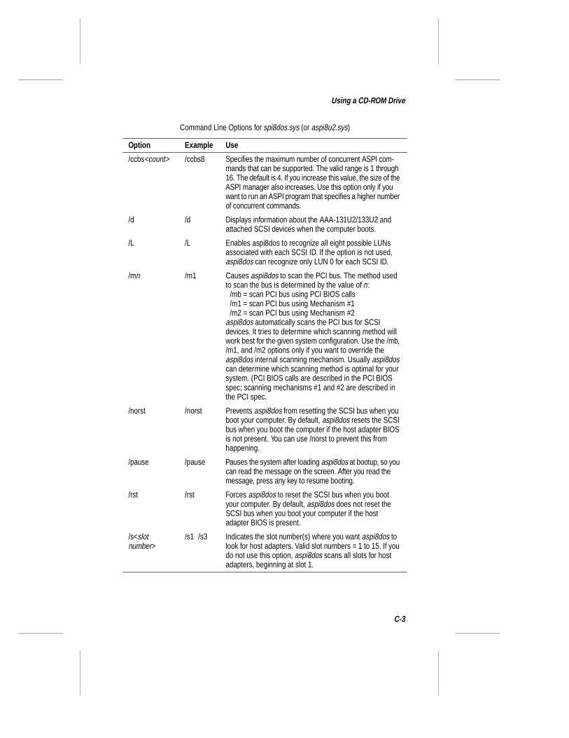
The following tables describe the aspi8u2.sys (or aspi8dos.sys) and aspicd.sys command line options. For a description of mscdex com-mand line options, see your Microsoft DOS documentation. You can type command line options in uppercase or lowercase letters. Leave a blank space between options.
C-2
Using a CD-ROM Drive
Command Line Options for spi8dos.sys (or aspi8u2.sys)
Option Example Use
/ccbs<count> /ccbs8 Specifies the maximum number of concurrent ASPI com-mands that can be supported. The valid range is 1 through 16. The default is 4. If you increase this value, the size of the ASPI manager also increases. Use this option only if you want to run an ASPI program that specifies a higher number of concurrent commands.
/d /d Displays information about the AAA-131U2/133U2 and attached SCSI devices when the computer boots.
/L /L Enables aspi8dos to recognize all eight possible LUNs associated with each SCSI ID. If the option is not used, aspi8dos can recognize only LUN 0 for each SCSI ID.
/mn /m1 Causes aspi8dos to scan the PCI bus. The method used to scan the bus is determined by the value of n :
/mb = scan PCI bus using PCI BIOS calls/m1 = scan PCI bus using Mechanism #1/m2 = scan PCI bus using Mechanism #2
aspi8dos automatically scans the PCI bus for SCSI devices. It tries to determine which scanning method will work best for the given system configuration. Use the /mb, /m1, and /m2 options only if you want to override the aspi8dos internal scanning mechanism. Usually aspi8dos can determine which scanning method is optimal for your system. (PCI BIOS calls are described in the PCI BIOS spec; scanning mechanisms #1 and #2 are described in the PCI spec.
/norst /norst Prevents aspi8dos from resetting the SCSI bus when you boot your computer. By default, aspi8dos resets the SCSI bus when you boot the computer if the host adapter BIOS is not present. You can use /norst to prevent this from happening.
/pause /pause Pauses the system after loading aspi8dos at bootup, so you can read the message on the screen. After you read the message, press any key to resume booting.
/rst /rst Forces aspi8dos to reset the SCSI bus when you boot your computer. By default, aspi8dos does not reset the SCSI bus when you boot your computer if the host adapter BIOS is present.
/s<slot number>
/s1 /s3 Indicates the slot number(s) where you want aspi8dos to look for host adapters. Valid slot numbers = 1 to 15. If you do not use this option, aspi8dos scans all slots for host adapters, beginning at slot 1.
C-3
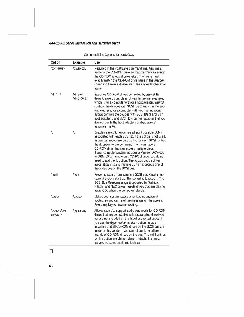
AAA-130U2 Series Installation and Hardware Guide
❒
Command Line Options for aspicd.sys
Option Example Use
/d:<name> /d:aspicd0 Required in the config.sys command line. Assigns a name to the CD-ROM drive so that mscdex can assign the CD-ROM a logical drive letter. The name must exactly match the CD-ROM drive name in the mscdex command line in autoexec.bat. Use any eight-character name.
/id={…} /id=2+4/id=3+5+1:4
Specifies CD-ROM drives controlled by aspicd. By default, aspicd controls all drives. In the first example, which is for a computer with one host adapter, aspicd controls the devices with SCSI IDs 2 and 4. In the sec-ond example, for a computer with two host adapters, aspicd controls the devices with SCSI IDs 3 and 5 on host adapter 0 and SCSI ID 4 on host adapter 1 (if you do not specify the host adapter number, aspicd assumes it is 0).
/L /L Enables aspicd to recognize all eight possible LUNs associated with each SCSI ID. If the option is not used, aspicd can recognize only LUN 0 for each SCSI ID. Add the /L option to the command line if you have a CD-ROM drive that can access multiple discs.If your computer system includes a Pioneer DRM-600 or DRM-604x multiple-disc CD-ROM drive, you do not need to add the /L option. The aspicd device driver automatically scans multiple LUNs if it detects one of these devices on the SCSI bus.
/norst /norst Prevents aspicd from issuing a SCSI Bus Reset mes-sage at system start-up. The default is to issue it. The SCSI Bus Reset message (supported by Toshiba, Hitachi, and NEC drives) resets drives that are playing audio CDs when the computer reboots.
/pause /pause Makes your system pause after loading aspicd at bootup, so you can read the message on the screen. Press any key to resume booting.
/type:<drive vendor>
/type:sony Allows aspicd to support audio play mode for CD-ROM drives that are compatible with a supported drive type but are not included on the list of supported drives. If you use the /type:<drive vendor> option, aspicd assumes that all CD-ROM drives on the SCSI bus are made by this vendor—you cannot combine different brands of CD-ROM drives on the bus. The valid entries for this option are chinon, denon, hitachi, lms, nec, panasonic, sony, texel, and toshiba.
C-4
'▼ ▼ ▼ ▼
Obtaining SCSI CablesIn this Appendix
High-quality cables are required in high-performance SCSI RAID systems to ensure data integrity. Adaptec provides the highest qual-ity SCSI cables designed specifically for use with Adaptec RAID cards. For purchasing information, contact Adaptec:
Adaptec, Inc.691 S. Milpitas BoulevardMilpitas, CA 95035USATel: 1-800-442-7274
Adaptec Europe - BelgiumTel: (32) 2-352-34-11Fax: (32) 2-352-34-00
Adaptec Japan - TokyoTel: (81) 3-5365-6700Fax: (81) 3-5365-6950
Adaptec SingaporeTel: (65) 278-7300Fax: (65) 273-0163
See the following pages for SCSI cables available directly from Adaptec.
➤ External Cables D-2➤ Internal Ribbon Cables D-2
D-1
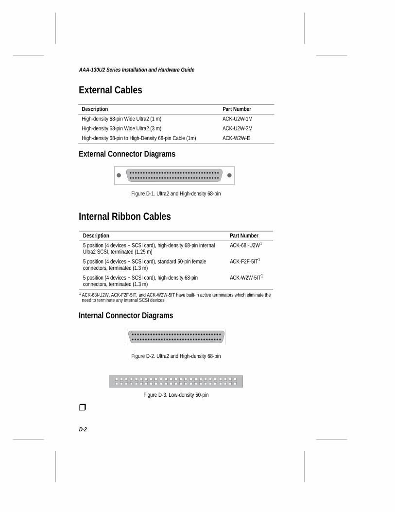
AAA-130U2 Series Installation and Hardware Guide
External Cables
External Connector Diagrams
Internal Ribbon Cables
Internal Connector Diagrams
❒
Description Part Number
High-density 68-pin Wide Ultra2 (1 m) ACK-U2W-1M
High-density 68-pin Wide Ultra2 (3 m) ACK-U2W-3M
High-density 68-pin to High-Density 68-pin Cable (1m) ACK-W2W-E
Description Part Number
5 position (4 devices + SCSI card), high-density 68-pin internal Ultra2 SCSI, terminated (1.25 m)
ACK-68I-U2W1
1 ACK-68I-U2W, ACK-F2F-5IT, and ACK-W2W-5IT have built-in active terminators which eliminate the need to terminate any internal SCSI devices
5 position (4 devices + SCSI card), standard 50-pin female connectors, terminated (1.3 m)
ACK-F2F-5IT1
5 position (4 devices + SCSI card), high-density 68-pin connectors, terminated (1.3 m)
ACK-W2W-5IT1
Figure D-1. Ultra2 and High-density 68-pin
Figure D-2. Ultra2 and High-density 68-pin
Figure D-3. Low-density 50-pin
D-2
▼ ▼ ▼ ▼ Index
AAdaptec CI/O Management
Software 1-3Array
booting from 3-8, B-2creating 3-4–3-7enclosure 2-9, 2-18optimized for data protection 3-3optimizing performance 3-3
ARRAYCONFIG U2 3-1–3-7aspi8dos.sys C-3aspicd.sys C-2
BBIOS
Array1000 A-2scan A-2, A-6sign-on message 2-19, B-1
Block size 3-7Board layout 2-2Boot partition B-2Bootable CD-ROM 4-2, A-2Booting
boot drive 3-4from an array 3-8, B-2
Bus parameters B-1
CCables
See SCSI CablesCache memory 2-3CD-ROM drive
install Windows NT 4-2
using under DOS C-1Channels 2-5, 2-6CMOS setup B-1Components 2-2Converters D-1
DDevices, connecting 2-9–2-17DIMM 1-2, 2-3Disconnection A-2, A-6Drivers
for DOS C-1for NetWare 5-2for UnixWare 6-2for Windows NT 4-2
EEnable disconnection A-2, A-6Enclosure, Array 2-9Expansion slot 2-4
FFormat disk 3-7, A-4
HHard disk drives 2-8Hardware installation 1-3Host adapter SCSI ID A-2
Index-1
AAA-130U2 Series Installation and Hardware Guide
IID numbers 2-6, 2-18, A-5, B-2IDE drives 2-5Include in BIOS scan A-6Initialize mode 3-7Initiate sync negotiation A-2, A-5Initiate wide negotiation A-6Installation 2-4
cache memory 2-3hints for connecting SCSI
devices 2-8local memory 2-3NetWare driver 5-2–5-8overview 1-3UnixWare driver 6-2–6-3Windows NT driver 4-2–4-4
IRQ B-1
LLED connector 2-5Local memory 2-3Low-level format 3-7LUNs C-4
MManager set diskettes 4-3, 4-4Memory, cache 2-3Memory, local 2-3Microsoft CD-ROM extensions C-1mscdex.exe C-1
NNetWare 5-1–5-8
cda1000h.ham 5-7, 5-8startup.ncf 5-4
PParameters B-1Parity checking A-5PCI bus 1-2
expansion slot 2-4parameters B-1
Power cables 2-19
RRAID 0 3-5RAID 0/1 3-5RAID 1 3-5RAID 5 3-5Requirements, system 1-2
SSCO UnixWare
see UnixWareSCSI
Array enclosures 2-18cables B-1, D-1channels 2-5, 2-6connecting devices 2-9–2-17converters D-1devices 2-6ID numbers 2-6, 2-18, A-5, B-2installation hints for devices 2-8parity checking A-5terminators 2-7, 2-18, A-2, A-5,
B-1SCSI parity checking A-2SCSISelect Utility 2-19, A-1–A-6Send start unit command A-2, A-6Spare disks 3-5startup.ncf 5-4Synchronous negotiation A-2, A-5Synchronous transfer rate A-2, A-5System requirements 1-2
Index-2
Index
TTermination 2-7, A-2, A-5, B-1Transfer rates A-2, A-5Troubleshooting B-1–B-3
UUnixWare 6-1–6-3
driver installation 6-2–6-3
VVerify disk media A-4
WWide negotiation A-6Windows NT 4-1–4-6
driver installation 4-2–4-4
❒
Index-3