Embed Size (px)
Citation preview

Kawasaki Robot MX Series, MD Series, MT400N
INSTALLATION AND
CONNECTION
Kawasaki Heavy Industries, Ltd.
90202-1066DEE
MX Series, MD Series, MT400N Kawasaki Robot Installation and Connection PREFACE This manual describes the installation and connection for the Kawasaki Robot MX series, MD series and MT400N. Read and understand the contents of this manual and the safety manuals thoroughly, and strictly observe all rules for safety before proceeding with any operation. This manual describes only the installation and connection of the robot arm section. Refer to separate Installation and Connection for controller and cables.
Never proceed with any operation until you understand the contents of this manual completely. Kawasaki is not responsible for any accidents and/or damages resulting from operations/ maintenance based on only a limited reading or limited understanding of some parts of this manual.
MX700N, MX500N, MX420L, MX350L, MD500N, MD400N, MT400N
This Manual is applicable to the following Robot Arms
1. This manual does not constitute a guarantee of the systems in which the robot is utilized. Accordingly, Kawasaki is not responsible for any accidents, damages, and/or problems relating to industrial property rights as a result of using the system.
2. It is recommended that all personnel assigned for activation of operation, teaching, maintenance or inspection of the robot attend the necessary education/training course(s) prepared by Kawasaki, before assuming their responsibilities.
3. Kawasaki reserves the right to change, revise, or update this manual without prior notice. 4. This manual may not, in whole or in part, be reprinted or copied without the prior written
consent of Kawasaki. 5. Store this manual with care and keep it available for use at any time. If the robot is
reinstalled or moved to a different site or sold off to a different user, attach this manual to the robot without fail. In the event the manual is lost or damaged severely, contact Kawasaki.
Copyright © 2011 Kawasaki Heavy Industries Ltd. All rights reserved.
1

MX Series, MD Series, MT400N Kawasaki Robot Installation and Connection SYMBOLS
The items that require special attention in this manual are designated with the following symbols. Ensure proper and safe operation of the robot and prevent physical injury or property damages by complying with the safety matters given in the boxes with these symbols.
Failure to comply with indicated matters can result in imminent injury or death.
DANGER!
Denotes precautions regarding robot specification, handling, teaching, operation, and maintenance.
[ NOTE ]
Failure to comply with indicated matters may possibly lead to injury or death.
WARNING!
Failure to comply with indicated matters may lead to physical injury and/or mechanical damage.
CAUTION!
1. The accuracy and effectiveness of the diagrams, procedures, and detail explanations given in this manual cannot be confirmed with absolute certainty. Accordingly, it is necessary to give one’s fullest attention when using this manual to perform any work.
2. Safety related contents described in this manual apply to each individual work and not to all robot work. In order to perform every work in safety, read and fully understand the safety manual, all pertinent laws, regulations and related materials as well as all the safety explanations described in each chapter, and prepare safety measures suitable for actual work.
WARNING !
2

MX Series, MD Series, MT400N Kawasaki Robot Installation and Connection
CONTENTS
1.0 Precautions.............................................................................................................................. 5 1.1 Precautions during Transportation and Storage..................................................................... 5 1.2 Installation Environments of Robot Arm ............................................................................ 11 2.0 Motion Range & Specifications of Robot ........................................................................... 12 2.1 Determination of Safety Fence Location Based on Motion Range – MX Series and
MT400N................................................................................................................................ 12 2.2 Determination of Safety Fence Location Based on Motion Range – MD Series .............. 13 2.3 Motion Range & Specifications........................................................................................... 14 3.0 Work Flow at Arm Installation and Connection ................................................................. 21 4.0 Robot Transportation Method.............................................................................................. 22 4.1 Wire Sling ............................................................................................................................. 22 4.2 Forklift................................................................................................................................... 23 5.0 Installing Dimensions of Base Section ................................................................................ 24 6.0 Movement Reaction Acting on Installation Surface during Operation .............................. 25 7.0 Installation Method............................................................................................................... 26 7.1 When Installing the Base Directly on the Floor: ................................................................. 26 7.2 When Installing the Base Plate with Positioning Holes on the Floor:................................ 26 7.3 When Installing with Installation Block: ............................................................................. 26 8.0 Mounting of Tools................................................................................................................ 27 8.1 Dimensions of Wrist End (Flange) ...................................................................................... 27 8.2 Specification of Mounting Bolt............................................................................................ 27 8.3 Allowable Load .................................................................................................................... 28 8.3.1 MX Series ............................................................................................................................. 29 8.3.2 MD Series ............................................................................................................................. 31 8.3.3 MT400N – When Load Mass is 380 kg or Less ................................................................. 36 8.3.4 MT400N – When Load Mass Exceeds 380 kg ................................................................... 37
3

MX Series, MD Series, MT400N Kawasaki Robot Installation and Connection 9.0 Connection of Air System.................................................................................................... 38 9.1 Air Piping Diagram .............................................................................................................. 38 9.2 Air Supply to the Robot Arm............................................................................................... 39 9.3 Connection to the Tool from the Air Outlet Ports............................................................... 40
4

MX Series, MD Series, MT400N 1. Precautions Kawasaki Robot Installation and Connection 1.0 PRECAUTIONS 1.1 PRECAUTIONS DURING TRANSPORTATION AND STORAGE When transporting the Kawasaki robot to its installation position, strictly observe the following precautions:
1. When transporting robot using a crane or a forklift, never support the robot manually.
2. During transportation, never climb on, or stay under the hoisted up robot. 3. Prior to starting installation, turn OFF controller power up to the external
power switch. Display signs indicating clearly “Installation in progress”, and lockout/tagout the external power switch to prevent the danger of electric shock and to stop personnel from accidentally turning ON the power.
4. When moving the robot, do not fail to ensure safety such as abnormality of installation conditions before turning ON the motor power. Then, set the robot to the desired posture. Be careful not to be caught by or between any moving parts of the robot due to careless approach to the robot at this time. After driving robot to the specified pose, turn OFF the power and lockout/tagout the external switch again as mentioned above, and start installation.
5. Warning labels are affixed to the arm to identify areas with possibility of electric shock, high temperature or pinching/crushing, so check these areas beforehand. See the next page for the warning labels and their positions.
! WARNING
1. Since the robot body is composed of precision parts, be careful not to apply excessive shocks or vibrations to the robot during transportation.
2. Prior to installing the robot, remove all obstacles so the installation is carried out smoothly and safely. Clear a passage to the install area for transportation of the robot using a crane or forklift.
3. During transportation and storage; (1) Keep the ambient temperature within -10 to 60 ˚C. (2) Ensure air is within 35 to 85 % relative humidity without dew condensation.(3) Ensure robot arm does not incur excessively strong shock and vibration.
! CAUTION
5

MX Series, MD Series, MT400N 1. Precautions Kawasaki Robot Installation and Connection MX500N, MX420L, MX350L warning label positions
: Warning label for electric shock
: Warning label for high temperature
: Warning label for pinching
6

MX Series, MD Series, MT400N 1. Precautions Kawasaki Robot Installation and Connection
7
MX700N warning label positions
: Warning label for electric shock
: Warning label for high temperature
: Warning label for pinching

MX Series, MD Series, MT400N 1. Precautions Kawasaki Robot Installation and Connection MD400N warning label positions
: Warning label for electric shock
: Warning label for high temperature
: Warning label for pinching
8
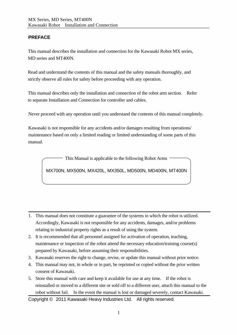
MX Series, MD Series, MT400N 1. Precautions Kawasaki Robot Installation and Connection MD500N warning label positions
:Warning label for electric shock
:Warning label for high temperature
:Warning label for pinching
9

MX Series, MD Series, MT400N 1. Precautions Kawasaki Robot Installation and Connection MT400N warning label positions
: Warning label for electric shock
: Warning label for high temperature
: Warning label for pinching
10

MX Series, MD Series, MT400N 1. Precautions Kawasaki Robot Installation and Connection
11
1.2 INSTALLATION ENVIRONMENTS OF ROBOT ARM Make sure that the following environmental conditions are satisfied.
1. When robot is installed on floor, the levelness must be within +/-5 °. 2. Be sure that the floor/stand has sufficient rigidity. 3. Secure a leveled place to prevent undue force application on the install position.
(If an accurate level is unobtainable, insert liners and adjust the height). 4. Keep the ambient temperature during operation within 0 to 45 °C. (Deviation or
overload error may occur due to high viscosity of grease/oil when starting operation at low temperatures. In this case, warm-up robot at low speed before regular operation.)
5. During operation, keep 35 to 85 % Relative Humidity without dew condensation. 6. The robot installing place should be free from dust, dirt, smoke, water, and other
foreign matters. (In dusty or moist conditions, use an Arm with dust-proof or waterproof spec.)
7. Robot installing place must be free from flammable or corrosive liquid or gas. (Use an explosion-proof arm in a flammable environment.)
8. The robot installing place should be free from excessively strong vibration. 9. The robot installing place should be free from electric noise interference. 10. The robot installing place must be sufficiently larger than the motion range of robot
arm. 11. Safety fence must be larger than the maximum movement of fully equipped robot arm
(with tools and workpiece) so it does not interfere with the surrounding objects. 12. Minimum number of entrance gates, optimally only one door, with a safety plug
provided on the safety fence.* Note* For safety fence spec. and construction, observe the requirements established for each
region. (e.g. EN953, EN294, EN811, EN1088, ISO13852, ISO13854, ISO/NP14120)
Mechanicalstopper
Motion range of robot arm (tools and workpiece included)
Gate with safety plug
Approx.1 m
Safety fence
Mechanicalstopper
Approx.1 m Approx.1 m
Approx.1 m Approx.1 m

MX Series, MD Series, MT400N 2. Motion Range & Specifications of Robot Kawasaki Robot Installation and Connection
12
2.0 MOTION RANGE & SPECIFICATIONS OF ROBOT 2.1 DETERMINATION OF SAFETY FENCE LOCATION BASED ON MOTION
RANGE – MX SERIES AND MT400N The motion range of robot arm is represented by Point P in figure below. Determine sum of L0+L1+L2 as minimum dimension from the center of arm (Point A in the figure), assuming; L0: Motion range of robot (See 2.3 Motion Range & Specifications.) L1: Dimension from the center of wrist to the edge of workpiece L2: Dimension of allowance
Motion Range at Point P
Tool
Workpiece
Point P Location
Point P Location
Point A
* The figure shows the motion range for MX500N.
Safety Fence L2
L1
L0
Location of Mechanical Stopper
Location of Mechanical Stopper

MX Series, MD Series, MT400N 2. Motion Range & Specifications of Robot Kawasaki Robot Installation and Connection 2.2 DETERMINATION OF SAFETY FENCE LOCATION BASED ON MOTION
RANGE – MD SERIES The motion range of robot arm is represented by Point P in figure below. Determine sum of L0+L1+L2 as minimum dimension from the center of arm (Point A in the figure), assuming; L0: Motion range of robot (See 2.3 Motion Range & Specifications.) L1: Dimension from the center of wrist to the edge of workpiece L2: Dimension of allowance
Motion Range at Point P
Point P Location
Point P Location
Point A Workpiece
Tool Note: For MD series, when moving JT5 with its posture of non-zero degree, its motion range
exceeds L0.
L2
L1
L0
Safety Fence
Location of Mechanical Stopper
Location ofMechanical Stopper
13

MX Series, MD Series, MT400N 2. Motion Range & Specifications of Robot Kawasaki Robot Installation and Connection 2.3 MOTION RANGE & SPECIFICATIONS MX700N
Type Articulated Robot Degree of Freedom
6
JT Motion Range Max. Speed 1 ±180° 65 °/s 2 +90° to -45° 50 °/s 3 +20° to -130° 45 °/s 4 ±360° 50 °/s 5 ±110° 50 °/s
Motion Range and
Maximum Speed
6 ±360° 95 °/s Max. Payload 700 kg
JT Torque Moment of Inertia 4 5488 N⋅m 600 kg⋅m2
5 5488 N⋅m 600 kg⋅m2
Wrist Load Capacity
6 2744 N⋅m 388 kg⋅m2
Repeatability ±0.5 mm Mass Approx. 2860 kg
Noise level < 70 db (A)*
*Measured condition
1. Robot installed on plate
rigidly fixed to floor
2. Measurement point is
4540 mm away from JT1
center
Noise level varies per
conditions.
14

MX Series, MD Series, MT400N 2. Motion Range & Specifications of Robot Kawasaki Robot Installation and Connection MX500N
Type Articulated Robot Degree of Freedom
6
JT Motion Range Max. Speed 1 ±180° 80 °/s 2 +90° to -45° 70 °/s 3 +20° to -130° 70 °/s 4 ±360° 80 °/s 5 ±110° 80 °/s
Motion Range and
Maximum Speed
6 ±360° 120 °/s Max. Payload 500 kg
JT Torque Moment of Inertia 4 3920 N⋅m 400 kg⋅m2
5 3920 N⋅m 400 kg⋅m2
Wrist Load Capacity
6 1960 N⋅m 259 kg⋅m2
Repeatability ±0.5 mm Mass Approx. 2750 kg
Noise level < 70 db (A)*
*Measured condition
1. Robot installed on plate
rigidly fixed to floor
2. Measurement point is
4540 mm away from JT1
center
Noise level varies per
conditions.
15

MX Series, MD Series, MT400N 2. Motion Range & Specifications of Robot Kawasaki Robot Installation and Connection
MX420L
Type Articulated Robot Degree of Freedom
6
JT Motion Range Max. Speed 1 ±180° 80 °/s 2 +90° to -45° 70 °/s 3 +20° to -125° 70 °/s 4 ±360° 80 °/s 5 ±110° 80 °/s
Motion Range and
Maximum Speed
6 ±360° 120 °/s Max. Payload 420 kg
JT Torque Moment of Inertia 4 3290 N⋅m 400 kg⋅m2
5 3290 N⋅m 400 kg⋅m2
Wrist Load Capacity
6 1960 N⋅m 259 kg⋅m2
Repeatability ±0.5 mm Mass Approx. 2800 kg
Noise level < 70 db (A)*
*Measured condition
1. Robot installed on plate
rigidly fixed to floor
2. Measurement point is
4780 mm away from JT1
center
Noise level varies per
conditions.
16

MX Series, MD Series, MT400N 2. Motion Range & Specifications of Robot Kawasaki Robot Installation and Connection
MX350L
Type Articulated Robot Degree of Freedom
6
JT Motion Range Max. Speed 1 ±180° 80 °/s 2 +90° to -45° 70 °/s 3 +20° to -115° 70 °/s 4 ±360° 80 °/s 5 ±110° 80 °/s
Motion Range and
Maximum *Measured condition
1. Robot installed on plate
rigidly fixed to floor
2. Measurement point is
5020 mm away from JT1
center
Noise level varies per
conditions.
Speed
6 ±360° 120 °/s Max. Payload 350 kg
JT Torque Moment of Inertia 4 2740 N⋅m 400 kg⋅m2
5 2740 N⋅m 400 kg⋅m2
Wrist Load Capacity
6 1960 N⋅m 259 kg⋅m2
Repeatability ±0.5 mm Mass Approx. 2800 kg
Noise level < 70 db (A)*
17

MX Series, MD Series, MT400N 2. Motion Range & Specifications of Robot Kawasaki Robot Installation and Connection MD400N
Type Articulated Robot Degree of Freedom
5
JT Motion Range Max. Speed 1 ±180° 80 °/s 2 +90° to -45° 70 °/s 3 +14° to -125° 70 °/s 4 ±360° 180 °/s 5 ±10° -
Motion Range and
Maximum Speed
*±10° from vertical downward posture Max. Payload 400 kg
JT Torque Moment of Inertia
*Measured condition
1. Robot installed on plate
rigidly fixed to floor
2. Measurement point is
5142 mm away from JT1
center
Noise level varies per
conditions.
Wrist Load Capacity 4 - 200 kg⋅m2
Repeatability ±0.5 mm Mass Approx. 2650 kg
Noise level < 70 db (A)*
18

MX Series, MD Series, MT400N 2. Motion Range & Specifications of Robot Kawasaki Robot Installation and Connection MD500N
Type Articulated Robot Degree of Freedom
5
JT Motion Range Max. Speed 1 ±180° 70 °/s 2 +90° to -45° 65 °/s 3 +14° to -125° 45 °/s 4 ±360° 160 °/s 5 ±10° -
Motion Range and
Maximum Speed
*±10° from vertical downward posture Max. Payload 500 kg
JT Torque Moment of Inertia
*Measured condition
1. Robot installed on plate
rigidly fixed to floor
2. Measurement point is
5142 mm away from JT1
center
Noise level varies per
conditions.
Wrist Load Capacity 4 - 250 kg⋅m2
Repeatability ±0.5 mm Mass Approx. 2680 kg
Noise level < 70 db (A)*
19

MX Series, MD Series, MT400N 2. Motion Range & Specifications of Robot Kawasaki Robot Installation and Connection MT400N
Type Articulated Robot Degree of Freedom
6
JT Motion Range Max. Speed 1 ±180° 80 °/s 2 +15° to -135° 70 °/s 3 +106° to -30° 70 °/s 4 ±360° 70 °/s 5 ±120° 70 °/s
Motion Range and
Maximum
*If load mass exceeds 380 kg,
the wrist flange surface should
face downward vertically
without fail.
**If load mass exceeds 380 kg,
see 8.3.4.
***Measured condition
1. Robot installed on plate
rigidly fixed to floor
2. Measurement point is 5020
mm away from JT1 center
Noise level varies per
conditions.
Speed
6 ±360° 130 °/s Max. Payload 400 kg*
JT Torque Moment of Inertia 4 2150 N⋅m 200 kg⋅m2
5 2150 N⋅m 200 kg⋅m2
Wrist Load Capacity** Load mass:
below 380 kg) 6 980 N⋅m 147 kg⋅m2
Repeatability ±0.5 mm Mass Approx. 2600 kg
Noise level < 70 db (A)***
20

MX Series, MD Series, MT400N 3. Work Flow at Arm Installation and Connection Kawasaki Robot Installation and Connection 3.0 WORK FLOW AT ARM INSTALLATION AND CONNECTION This flowchart describes only the robot arm section. For the details on the controller, refer to separate Installation and Connection for Controller.
Refer to "2. Motion Range and Specifications of Robot".
Connection to Controller
Examination & Preparation of Installation Plane Surface
Refer to "5. Installing Dimensions of Base Section", "7. Installation Method".
Refer to "5. Installing Dimensions of Base Section", "6. Movement Reaction Acting on the Installation Surface during Operation", "7. Installation Method".
Refer to "Installation and Connection Manual" for controller.
Transportation of Robot ArmRefer to "4. Robot Transportation Method".
Check of Arm Motion Check of Tool Motion
Mounting of Tools
Check of Other Functions
Refer to "8. Mounting of Tools" and
Refer to "Operation Manual".
Refer to "Operation Manual".
Installation of Robot Arm
Prep
arat
ion
Examination of Installation Place and Motion Range
Actu
al W
ork
"9. Connection of Air System".
Wor
k U
sing
Con
trolle
r
Completion of Work
21

MX Series, MD Series, MT400N 4. Robot Transportation Method Kawasaki Robot Installation and Connection 4.0 ROBOT TRANSPORTATION METHOD 4.1 WIRE SLING
3 Wires3 Wires 3 Wires
MD Series MX Series MT400N According to the figure, hoist up the robot by threading three wires through three eyebolts. Eyebolts (3 positions)
Before lifting via wire sling, set angles of each arm axis as shown in table below.
Model MX Series MD Series MT400N
JT1 0 ° 0 ° 0 ° JT2 -45 ° -45 ° 70 ° JT3 -23 ° -20 ° -135 ° JT4 0 ° 0 ° 0 ° JT5 0 ° 0 ° 70 °
Angle
JT6 - 0 ° 0 °
1. When hoisting up the robot, be careful as robot may lean forward/backward depending on robot posture and mounting condition of the tool and options.
2. If the robot is hoisted up in an inclined posture, it may swing, or the wire may interfere with the wrist motor, harness, piping etc., or it may be damaged from interfering with surrounding objects.
3. Protect the robot with wear plates, etc. if wires interfere with a part of the robot (balancer, etc.).
! CAUTION
22

MX Series, MD Series, MT400N 4. Robot Transportation Method Kawasaki Robot Installation and Connection 4.2 FORKLIFT When carrying the robot by forklift, use the optional forklift jig which can be attached to the arm base.
MT400N
Fork pocket
MD500N
1. When carrying MX series and MD series robot by forklift, set the robot posture so that JT2 is between 0° and -45°.
2. When carrying MD400N robot by forklift, set the robot posture so that JT2 is -135°.
3. Confirm that the forks of forklift penetrate sufficiently without fail. 4. When transporting robot on an inclined or rough surface, be careful to
maintain balance to prevent forklift/robot from falling.
! CAUTION
MX500N, MX420L, MX350L MD400N MX700N
Fork pocket (1964.1 , Fork pocket
23

MX Series, MD Series, MT400N 5. Installing Dimensions of Base Section Kawasaki Robot Installation and Connection 5.0 INSTALLING DIMENSIONS OF BASE SECTION When installing base section, fix it with high tension bolts utilizing the bolt holes.
Installing Dimensions of Base
Section
Cross-section of Base Installation
Hole
Bolt Hole 8-φ22 8-M20
High Tension Bolt Material: SCM435 Strength class: 10.9 min.
Tightening Torque 431.2 N⋅m
Levelness Within +/-5°
24

MX Series, MD Series, MT400N 6. Movement Reaction Acting on Installation Surface Kawasaki Robot Installation and Connection during Operation 6.0 MOVEMENT REACTION ACTING ON INSTALLATION SURFACE DURING
OPERATION Refer to the list below for the movement reaction that acts on the installation surface during operation. Consider these values at installation shown in the following pages. (1) During Repeat operation
Model MX700N MX500N MX420L MX350L MD500N MD400N MT400N
M 48000 N⋅m
48000 N⋅m
43500 N⋅m
40000 N⋅m
37000 N⋅m
44500 N⋅m
46500 N⋅m (Inversion
Moment) T 15500
N⋅m 15500 N⋅m
14500 N⋅m
13500 N⋅m
14000 N⋅m
11500 18500 N⋅m (Rotating
Torque) N⋅m
(2) When robot has interfered with an obstacle during Teach mode*
Model MX700N MX500N MX420L MX350L MD500N MD400N MT400N
M 76000 N⋅m
82000 N⋅m
71000 63000 63000 N⋅m
58000 58000 (Inversion Moment) N⋅m N⋅m N⋅m N⋅m
T 15500 N⋅m
15500 N⋅m
15500 15500 15500 N⋅m
15500 18500 (Rotating Torque) N⋅m N⋅m N⋅m N⋅m
Note* Reaction forces when the arm interferes with obstacles in teach mode
25

MX Series, MD Series, MT400N 7. Installation Method Kawasaki Robot Installation and Connection 7.0 INSTALLATION METHOD 7.1 WHEN INSTALLING THE BASE DIRECTLY ON THE FLOOR: As shown below, bury steel plate (35 mm min. thick) in the concrete floor or fix with anchor bolts. The steel plate must be fixed firmly enough to sustain reaction forces by the robot.
M20
M T
Concrete
Steel plate 35 mmmin.
30 mmmin.
Tightening torque 431.2 N⋅m
7.2 WHEN INSTALLING THE BASE PLATE WITH POSITIONING HOLES ON THE
FLOOR: Install the base plate utilizing 8 holes of φ22. Install the base plate on the concrete floor or the steel plate floor. Reaction forces received from robot arm are the same as when installing the base directly on the floor. There are two pin holes on the base plate for positioning, which enable the base plate to join with the base easily by orienting the holes on the robot base side to the pin holes. Replacement of a broken robot, etc. can be done quickly and easily by orienting the holes.* Note* Precise zeroing of JT1 is required to use this function, which is an Option. 7.3 WHEN INSTALLING WITH INSTALLATION BLOCK:
Base
200 mm or more
200
mm
or m
ore
Thickness 32 mm or more
Base Install an installation block that satisfies the dimensions in right figure.
26
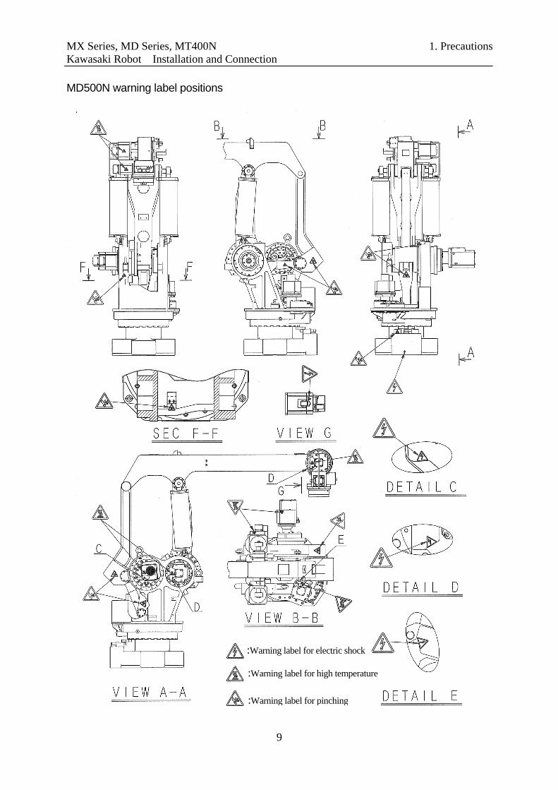
MX Series, MD Series, MT400N 8. Mounting of Tools Kawasaki Robot Installation and Connection 8.0 MOUNTING OF TOOLS
When mounting tools, turn OFF controller power up to the external power switch. Display signs indicating clearly “Installation in progress”, and lockout/tagout the external power switch to prevent the danger of electric shock and to stop personnel from accidentally turning ON the power.
! WARNING 8.1 DIMENSIONS OF WRIST END (FLANGE) At the end of robot arm, a flange is provided for mounting a tool. Tighten the mounting bolts into the tap holes machined on circumference of φD as shown below. Position tool with the pin holes and spigot hole.
MT400N flangeMX and MD series flange
Pin holes 8.2 SPECIFICATION OF MOUNTING BOLT The length of mounting bolt should be selected depending on the tap depth of tool mounting flange. Moreover, the mounting bolt should be a high tension bolt and tightened with the specified torque.
Spigot hole
φD
If the length of engagement (screw depth) exceeds the specified depth, the mounting bolt bottoms out and tools cannot be fixed with certainly.
! CAUTION
Tool mountingsection (Flange)
Tool
Mounting bolt
Check depth (length of engagement)
Check tightening torque
Pin holes
Spigot hole
Tapped holes
φD
Tapped holes Use at least one pin for assured fixing to prevent the tool on the flange from moving.
! CAUTION
27

MX Series, MD Series, MT400N 8. Mounting of Tools Kawasaki Robot Installation and Connection
MX700N MX500N MX420L Model MT400N MX350L MD500N MD400N
Tapped holes 6-M12 6-M10 φD φ200 φ160
Pin holes 2-φ12H7 Depth 12 2-φ10H7 Depth 12 Spigot hole φ125H7 Depth 8.5 φ100H7 Depth 8 Tap depth 29 mm 12 mm
Screwing depth 18∼28 mm 10∼11 mm High tension bolt SCM435, 10.9 Min SCM435, 10.9 Min Tightening torque 98.07 N⋅m 98.07 N⋅m
S45C H * S45CH * Pin Material NOTE* S45C thermal refining steel or equivalent in strength 8.3 ALLOWABLE LOAD The maximum payload is specified for each robot model. Mass of tools, etc. is considered payload and must be included when summing the arm’s total payload for the application. Also, the allowable moment of load and the moment of inertia in wrist section (JT4, JT5, JT6) should be calculated by the expressions on the next page.
1. Be advised that using the robot arm to grasp an overrated payload may degrade the arm’s motion ability or shorten its service life.
2. Calculate total load to be carried by robot arm as the sum of the mass of hand, gun, tool changer, etc. as well as any work being grasped during the application. Ensure sum is less than the maximum payload specified for the arm model.
3. If the total payload exceeds the max. allowed payload for arm, consult with Kawasaki before starting operations.
! CAUTION
28
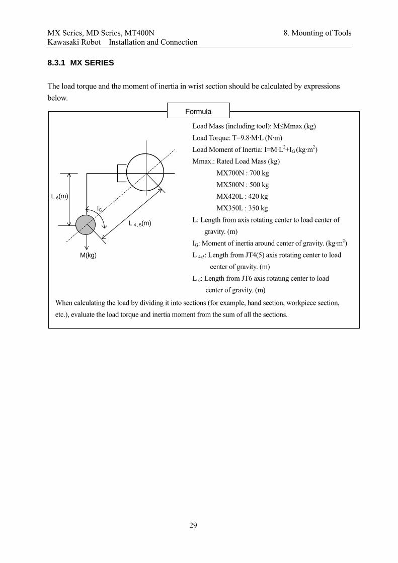
MX Series, MD Series, MT400N 8. Mounting of Tools Kawasaki Robot Installation and Connection 8.3.1 MX SERIES The load torque and the moment of inertia in wrist section should be calculated by expressions below.
When calculating the load by dividing it into sections (for example, hand section, workpiece section, etc.), evaluate the load torque and inertia moment from the sum of all the sections.
Formula
Load Mass (including tool): M≤Mmax.(kg) Load Torque: T=9.8·M·L (N·m)
L 6(m)
L 4 , 5(m)
M(kg)
IG
Load Moment of Inertia: I=M·L2+I (kg·m2) G
Mmax.: Rated Load Mass (kg) MX700N : 700 kg MX500N : 500 kg MX420L : 420 kg MX350L : 350 kg L: Length from axis rotating center to load center of
gravity. (m) IG: Moment of inertia around center of gravity. (kg·m2) L 4,5: Length from JT4(5) axis rotating center to load
center of gravity. (m) L 6: Length from JT6 axis rotating center to load
center of gravity. (m)
29
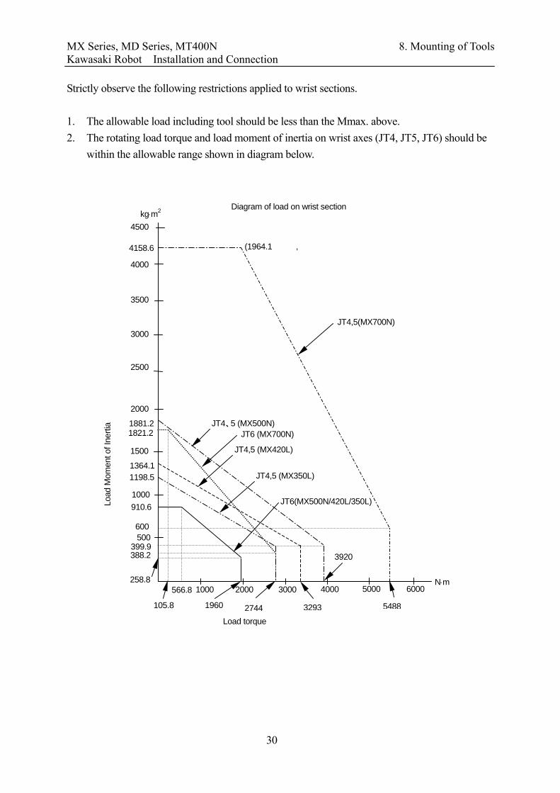
MX Series, MD Series, MT400N 8. Mounting of Tools Kawasaki Robot Installation and Connection Strictly observe the following restrictions applied to wrist sections. 1. The allowable load including tool should be less than the Mmax. above. 2. The rotating load torque and load moment of inertia on wrist axes (JT4, JT5, JT6) should be
within the allowable range shown in diagram below.
Load
Mom
ent o
f Ine
rtia
40003000
1000
500
258.8 20001000
kg⋅m2
N⋅m
1500
2000
399.9
566.8
1960 2744 3293
3920
Diagram of load on wrist section
910.6
1198.5 1364.1
1881.2 JT4、5 (MX500N)
JT4,5 (MX420L)
JT4,5 (MX350L)
JT6(MX500N/420L/350L)
4500
4000
3500
3000
2500
6000 5000
4158.6
5488
600
105.8
1821.2 JT6 (MX700N)
JT4,5(MX700N)
388.2
(1964.1 ,
Load torque
30

MX Series, MD Series, MT400N 8. Mounting of Tools Kawasaki Robot Installation and Connection 8.3.2 MD SERIES The load torque and the moment of inertia in wrist section should be calculated by expressions below.
When calculating the load by dividing it into sections (for example, hand section, workpiece section, etc.), evaluate the inertia moment from the sum of all the sections.
Formula
L z (m)
M(kg)
IGL 4 (m)
Load Mass (including tool): M≤Mmax.(kg) Load Torque: not specified
Strictly observe the following restrictions applied to wrist sections. 1. The allowable load including tool should be less than the Mmax. above. 2. Restrictions are applied to the load moment of inertia in wrist section (JT4). The load
moment of inertia should be below 200 kg·m2. 3. Restrictions are applied to the center of gravity. The center should be positioned within the
allowable range shown below. There are two diagrams; when moving with JT5 facing vertically down (0º) and when moving with JT5 tilted (within +/- 10º of vertical down).
4. Even if the load is less than 100 kg, the center position of gravity should be within 100kg shown in the Diagram of load on wrist section.
Load Moment of Inertia: I=M·L2+IG (kg·m2) ≤Imax (kg·m2) Center Position of Gravity (L 4, Lz): See diagrams below. Mmax.: Rated Load Mass 400 (kg) Imax.: Rated Load Moment of inertia 200 (kg·m2) IG: Moment of inertia around center of gravity. (kg·m2) Lz: Length from flange to load center of gravity. (m) L 4: Length from JT4 axis rotating center to load center of
gravity. (m)
31

MX Series, MD Series, MT400N 8. Mounting of Tools Kawasaki Robot Installation and Connection
32
Diagram of load on wrist section (MD500N, JT5:0°)
200222.2 250.0 285.7 333.3
400 500
720.0800.0900.0
1028.61200.0
1440.0
2400.0
1800.0
3600.0
(200.0, 400.0)
(285.7, 571.4)(333.3, 666.7)(400.0, 800.0)
(222.2, 444.4)
(500.0, 1000.0)
(500.0, 2800.0)
(250.0, 500.0)
100 400.0 500.0
300
Leng
th fr
om fl
ange
Lz (
mm
)
1000
2000
3000
4000
100 kg
150 kg
200 kg
250 kg
300 kg
400 kg
500 kg 450 kg
Length from JT4 axis rotating center L4 (mm)
0
(1964.1
(500.0, 1600.0)

MX Series, MD Series, MT400N 8. Mounting of Tools Kawasaki Robot Installation and Connection
33
Diagram of load on wrist section (MD500N, JT5: within +/-10°) Length from JT4 axis rotating center L4 (mm)
400 100 500 200 3000
500
1000
1500
2000
2500
z
492.9
555.9634.7
1061.3
1346.0
1823.3
2472.2
435.9 11131.3 53.8 82.1 334.4218.3 266.7
736.2871.6
(54.6, 435.0)
(139.6, 720.8)(109.2, 618.7)
(86.5, 542.2) (68.7, 482.7)
(141.6, 1668.9)
(245.8, 1078.0)
500 kg
100 kg
150 kg
200 kg
250 kg
300 kg
400 kg
450 kg
350 kg
(182.1, 863.7)
Leng
th fr
om fl
ange
Lz (
mm
)

MX Series, MD Series, MT400N 8. Mounting of Tools Kawasaki Robot Installation and Connection
Diagram of load on wrist section (MD400N, JT5:0°) Length from JT4 axis rotating center L4 (mm)
500400100 300200
Leng
th fr
om fl
ange
Lz (
mm
)
1000
2000
3000
0 400.0285.7 333.3250.0 500.0(250.0, 500.0)
(285.7, 571.4)
(333.3, 666.7)
400 kg (400.0, 800.0)900.0 (500.0, 1000.0)350 kg
300 kg 1028.6250 kg 1200.0
(500.0, 1600.0)1440.0 200 kg 1800.0
150 kg 2400.0
(500.0, 2800.0)
100 kg
3600.0
4000
34

MX Series, MD Series, MT400N 8. Mounting of Tools Kawasaki Robot Installation and Connection
Length from JT axis rotating center L4 (mm)
Diagram of load on wrist section (MD400N, JT5: within +/-10°)
Leng
th fr
om fl
ange
L z (m
m)
1000
500
1500
2000
2500
0200 300 400 500100
179.8 216.1 264.4 332.1 433.7
625.4
727.2863.0
1053.1
1338.2
1813.4
2459.4
(245.8, 1065.3)
(141.6, 1656.1)
(182.1, 850.9)
(139.6, 708.0)
(109.2, 606.0)
(86.4, 529.4)
100 kg
200 kg
250 kg
300 kg
400 kg
350 kg
(1964.1 ,
35

MX Series, MD Series, MT400N 8. Mounting of Tools Kawasaki Robot Installation and Connection 8.3.3 MT400N – WHEN LOAD MASS IS 380 KG OR LESS
The load torque and the moment of inertia in wrist section should be calculated by expressions below.
When calculating the load by dividing it into sections (for example, hand section, workpiece section, etc.),evaluate the load torque and inertia moment from the sum of all the sections.
Formula
Load Mass (including tool): M≤Mmax.(kg) Load Torque: T=9.8·M·L (N·m) Load Moment of Inertia: I=M·L2+IG (kg·m2) Mmax. = 380 kg L: Length from axis rotating center to load center of gravity.
(m) IG: Moment of inertia around center of gravity. (kg·m2) L 4,5: Length from JT4(5) axis rotating center to load center
of gravity. (m) L 6: Length from JT6 axis rotating center to load center of
gravity. (m)
L 6(m)
L 4, 5(m)
M (kg)
IG
Strictly observe the following restrictions applied to wrist sections. 1. The allowable load including tool should be less than the Mmax. above. 2. The rotating load torque and load moment of inertia on wrist axes (JT4, JT5, JT6) should be
within the allowable range shown in diagram below.
Diagram of load on wrist section1000
900
800
700
600
500
400
300
200
100
00 500 1000 1500 2000 2500
Load torque
Load
mom
ent o
f ine
rtia
kg・m2
N・m
JT4,5 JT6
(1964.1 ,
(980.0, 147.0)
(1479.0, 906.0)
(2150.0, 200.0) 214.6
906
2150 980
36

MX Series, MD Series, MT400N 8. Mounting of Tools Kawasaki Robot Installation and Connection 8.3.4 MT400N – WHEN LOAD MASS EXCEEDS 380 KG
If the load mass exceeds 380 kg, the wrist flange surface should face downward vertically without fail. The moment of inertia in wrist section should be calculated by expressions below.
Strictly observe the following restrictions applied to wrist sections. 1. The allowable load including tool should be less than the Mmax. above. 2. Restrictions are applied to the load moment of inertia in wrist section (JT4). The load
moment of inertia should be below 147 kg·m2. 3. Restrictions are applied to the center of gravity. The center should be positioned within the
allowable range shown below.
When calculating the load by dividing it into sections (for example, hand section, workpiece section, etc.),evaluate the load torque and inertia moment from the sum of all the sections.
Formula
Load Mass (including tool): M≤Mmax.(kg)
L z (m)
M (kg)
Load Torque: not specified
IGL 6 (m)
Load Moment of Inertia: I=M·L2+IG (kg·m2) ≤Imax.(kg・m2) Center Position of Gravity (L 6, L Z): See the diagram of load on wrist section. Mmax.: Rated Load Mass 400 (kg) Imax. : Rated Load Mass 147 (kg m2) IG: Moment of inertia around center of gravity. (kg·m2) L z: Length from flange to load center of gravity (m) L 6: Length from JT6 axis rotating center to load center of gravity.
Diagram of load on wrist sectionLength from JT6 axis rotating center L6 (mm)
Leng
th fr
om fl
ange
L z (m
m)
0.0
50.0
100.0
150.0
200.0
250.0
300.0
0.0 50.0 100.0 150.0 200.0 250.0 300.0 350.0 450.0400.0
37 350.0
374.1
301.3

MX Series, MD Series, MT400N 9. Connection of Air System Kawasaki Robot Installation and Connection 9.0 CONNECTION OF AIR SYSTEM 9.1 AIR PIPING DIAGRAM MX series includes air piping for driving tool in the robot arm. 1. MX Series/MT400N The following valves can be installed on above-mentioned arm as Option. The valve can be set ON/OFF by the Multi Function Panel (or, Teach Pendant) without need for wiring via interlock.
Robot Base Section Internal Robot Arm Upper Arm Section of Robot
φ12 single touch joint R 3/8 Joint for air (Input: 0.147 to 0.588 MPa)
●AIR1 ●AIR1
○AIR2 ○AIR2
AIR1 (black tube)
AIR2 (white tube)
Single Solenoid Valve 1 unit Single Solenoid Valve 2 units Single Solenoid Valve 3 units Double Solenoid Valve 1 unit Double Solenoid Valve 2 units Double Solenoid Valve 3 units
Option
Single Solenoid Valve 1 unit + Double Solenoid Valve 1 unit Single Solenoid Valve 1 unit + Double Solenoid Valve 2 units Single Solenoid Valve 2 units + Double Solenoid Valve 1 unit
Note: The valve specification is: CV value = 3.2 and 2-position.
38

MX Series, MD Series, MT400N 9. Connection of Air System Kawasaki Robot Installation and Connection 2. MD Series
R 3/8 Joint for air
Robot Base Section Internal Robot Arm Upper Arm Section of Robot
R 3/8 Joint for air (Input: 0.147 to 0.588 MPa)
●AIR1 ●AIR1
○AIR2 ○AIR2
AIR1 (black tube) AIR2 (white tube) Note: A vacuum hose with an internal diameter of 1 inch can be added as Option. 9.2 AIR SUPPLY TO THE ROBOT ARM As shown in the figure below, air connection ports are provided on the base section of robot arm.
Supply air to the air inlet ports (R 3/8 ports, 2 places). Air pressure; 0.15 to 0.6 MPa
! CAUTION
Air inlet(AIR1) Air inlet(AIR2)
39
MX Series, MD Series, MT400N 9. Connection of Air System Kawasaki Robot Installation and Connection
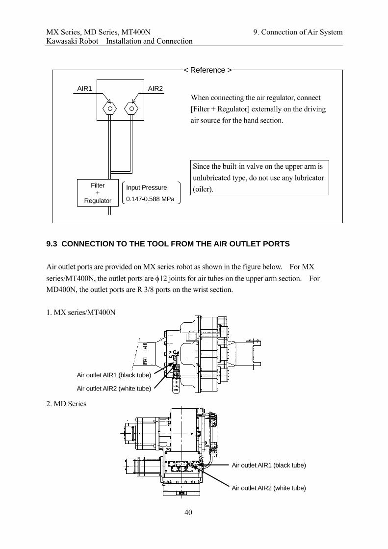
Since the built-in valve on the upper arm is unlubricated type, do not use any lubricator (oiler).
When connecting the air regulator, connect [Filter + Regulator] externally on the driving air source for the hand section.
< Reference >
Filter +
Regulator
Input Pressure
0.147-0.588 MPa
AIR1 AIR2
9.3 CONNECTION TO THE TOOL FROM THE AIR OUTLET PORTS Air outlet ports are provided on MX series robot as shown in the figure below. For MX series/MT400N, the outlet ports are φ12 joints for air tubes on the upper arm section. For MD400N, the outlet ports are R 3/8 ports on the wrist section. 1. MX series/MT400N
Air outlet AIR2 (white tube)
Air outlet AIR1 (black tube)
2. MD Series
エア取出口
Air outlet AIR2 (white tube)
Air outlet AIR1 (black tube)
40

KAWASAKI ROBOT MX Series, MD Series, MT400N
Installation and Connection
April 2003 : 1st Edition June 2011 : 5th Edition
Publication: KAWASAKI HEAVY INDUSTRIES, LTD.
90202-1066DEE
Copyright© 2011 KAWASAKI HEAVY INDUSTRIES, LTD. All rights reserved.