Embed Size (px)
Citation preview

Relion® 670 series
Transformer protection RET670 ANSIInstallation and commissioning manual

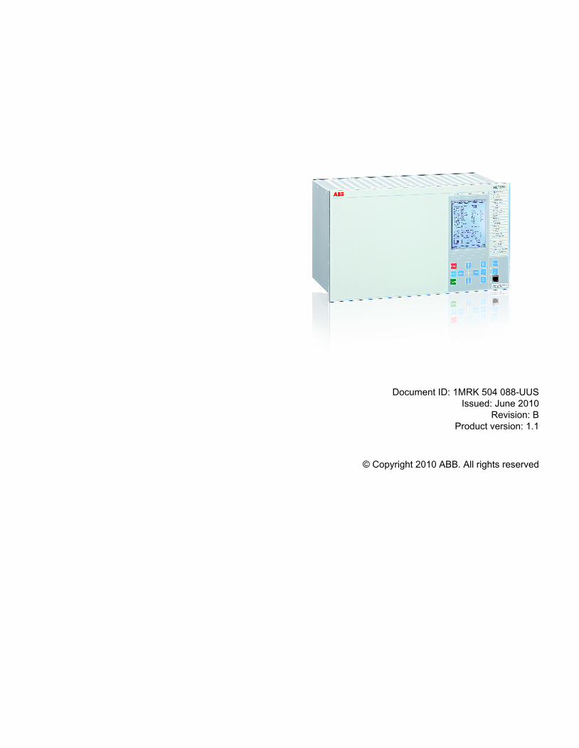
Document ID: 1MRK 504 088-UUSIssued: June 2010
Revision: BProduct version: 1.1
© Copyright 2010 ABB. All rights reserved

CopyrightThis document and parts thereof must not be reproduced or copied without writtenpermission from ABB, and the contents thereof must not be imparted to a third party,nor used for any unauthorized purpose.
The software or hardware described in this document is furnished under a license andmay be used or disclosed only in accordance with the terms of such license.
TrademarksABB and Relion are registered trademarks of ABB Group. All other brand or productnames mentioned in this document may be trademarks or registered trademarks of theirrespective holders.
WarrantyPlease inquire about the terms of warranty from your nearest ABB representative.
ABB Inc.
940 Main Campus Drive
Raleigh, NC 27606, USA
Toll Free: 1-800-HELP-365, menu option #8
ABB Inc.
3450 Harvester Road
Burlington, ON L7N 3W5, Canada
Toll Free: 1-800-HELP-365, menu option #8
ABB Mexico S.A. de C.V.
Paseo de las Americas No. 31 Lomas Verdes 3a secc.
53125, Naucalpan, Estado De Mexico, MEXICO
Phone: (+1) 440-585-7804, menu option #8

DisclaimerThe data, examples and diagrams in this manual are included solely for the concept orproduct description and are not to be deemed as a statement of guaranteed properties.All persons responsible for applying the equipment addressed in this manual mustsatisfy themselves that each intended application is suitable and acceptable, includingthat any applicable safety or other operational requirements are complied with. Inparticular, any risks in applications where a system failure and/or product failure wouldcreate a risk for harm to property or persons (including but not limited to personalinjuries or death) shall be the sole responsibility of the person or entity applying theequipment, and those so responsible are hereby requested to ensure that all measuresare taken to exclude or mitigate such risks.
This document has been carefully checked by ABB but deviations cannot becompletely ruled out. In case any errors are detected, the reader is kindly requested tonotify the manufacturer. Other than under explicit contractual commitments, in noevent shall ABB be responsible or liable for any loss or damage resulting from the useof this manual or the application of the equipment.

ConformityThis product complies with the directive of the Council of the European Communitieson the approximation of the laws of the Member States relating to electromagneticcompatibility (EMC Directive 2004/108/EC) and concerning electrical equipment foruse within specified voltage limits (Low-voltage directive 2006/95/EC). Thisconformity is the result of tests conducted by ABB in accordance with the productstandards EN 50263 and EN 60255-26 for the EMC directive, and with the productstandards EN 60255-1 and EN 60255-27 for the low voltage directive. The IED isdesigned in accordance with the international standards of the IEC 60255 series andANSI C37.90.
Table of contents
Section 1 Introduction..........................................................................11Introduction to the installation and commissioning manual....................11
About the complete set of manuals for an IED..................................11About the installation and commissioning manual.............................12Intended audience.............................................................................13Related documents............................................................................13Revision notes...................................................................................14
Section 2 Safety information...............................................................15Warning signs.........................................................................................15Caution signs..........................................................................................16Note signs...............................................................................................17
Section 3 Overview.............................................................................19Commissioning and installation overview...............................................19
Section 4 Unpacking and checking the IED........................................21Taking delivery, unpacking and checking...............................................21
Section 5 Installing the IED.................................................................23Overview.................................................................................................23Dimensions.............................................................................................24
Case without rear cover.....................................................................24Case with rear cover..........................................................................26Flush mounting dimensions...............................................................28Side-by-side flush mounting dimensions...........................................29Wall mounting dimensions.................................................................31
Mounting methods and details................................................................32Mounting the IED...............................................................................32Flush mounting..................................................................................33
Overview.......................................................................................33Mounting procedure for flush mounting........................................35
19” panel rack mounting....................................................................36Overview.......................................................................................36Mounting procedure for 19” panel rack mounting.........................37
Wall mounting....................................................................................38Overview.......................................................................................38
Table of contents
1Installation and commissioning manual
Mounting procedure for wall mounting.........................................39How to reach the rear side of the IED..........................................40
Side-by-side 19” rack mounting.........................................................41Overview.......................................................................................41Mounting procedure for side-by-side rack mounting....................41IED in the 670 series mounted with a RHGS6 case.....................42
Side-by-side flush mounting..............................................................43Overview.......................................................................................43Mounting procedure for side-by-side flush mounting....................44
Making the electrical connection.............................................................45IED connectors..................................................................................45
Overview.......................................................................................45Front side connectors...................................................................47Rear side connectors....................................................................48Connection examples...................................................................58
Connecting to protective ground........................................................62Connecting the power supply module...............................................63Connecting to CT and VT circuits......................................................64
Configuration for analog CT inputs...............................................65Connecting the binary input and output signals.................................65Making the screen connection...........................................................68
Making the optical connections...............................................................69Connecting station communication interfaces...................................69Connecting remote communication interfaces LDCM.......................70
Installing the serial communication cable for RS485..............................70RS485 serial communication module................................................70Installing the serial communication cable for RS485 SPA/IEC..........74Data on RS485 serial communication module cable.........................76
Installing the GPS antenna.....................................................................77Antenna installation...........................................................................77Electrical installation..........................................................................78Lightning protection...........................................................................79
Section 6 Checking the external optical and electricalconnections.........................................................................81Overview.................................................................................................81Checking VT circuits...............................................................................81Checking CT circuits...............................................................................82Checking the power supply.....................................................................83Checking the binary I/O circuits..............................................................83
Table of contents
2Installation and commissioning manual
Binary input circuits............................................................................83Binary output circuits.........................................................................83
Checking optical connections.................................................................83
Section 7 Energizing the IED..............................................................85Check the IED operation.........................................................................85Energizing the IED..................................................................................85Design.....................................................................................................86Checking the self supervision signals.....................................................88
Reconfiguring the IED.......................................................................88Setting the IED time...........................................................................88Checking the self supervision function..............................................88
Determine the cause of an internal failure....................................88Self supervision HMI data..................................................................89
Section 8 Set up the PCM600 communication link per IED................91Setting up communication between PCM600 and the IED.....................91
Section 9 Establishing connection and verifying the SPA/IEC-communication ...................................................................97Entering settings.....................................................................................97
Entering SPA settings........................................................................97Entering IEC settings.........................................................................98
Verifying the communication...................................................................98Verifying SPA communication...........................................................98Verifying IEC communication............................................................99
Fibre optic loop.......................................................................................99Optical budget calculation for serial communication with SPA/IEC .....101
Section 10 Establishing connection and verifying the LONcommunication .................................................................103Communication via the rear ports ........................................................103
LON communication........................................................................103The LON Protocol............................................................................105Hardware and software modules.....................................................105
Optical budget calculation for serial communication with LON ............107
Section 11 Establishing connection and verifying the IEC 61850communication..................................................................109Overview...............................................................................................109Setting the station communication........................................................109Verifying the communication.................................................................110
Table of contents
3Installation and commissioning manual
Section 12 Configuring the IED and changing settings.......................111Overview...............................................................................................112Entering settings through the local HMI................................................112Configuring analog CT inputs...............................................................113Downloading settings and configuration from a PC..............................114
Writing an application configuration to the IED................................114
Section 13 Verifying settings by secondary injection .........................115Overview...............................................................................................115Preparing for test..................................................................................116
Preparing the IED to verify settings.................................................116Preparing the connection to the test equipment..............................117Activating test mode........................................................................118Connecting test equipment to the IED.............................................118Verifying analog primary and secondary measurement..................119Releasing the function to be tested.................................................120Disturbance report...........................................................................121
Introduction.................................................................................121Disturbance report settings.........................................................121Disturbance recorder (DR).........................................................121Event recorder (ER) and Event list (EL).....................................122
Identifying the function to test in the technical referencemanual ............................................................................................123Exit test mode..................................................................................123
Basic IED functions...............................................................................123Parameter setting group handling SETGRPS.................................123
Verifying the settings..................................................................123Completing the test.....................................................................124
Differential protection............................................................................124Transformer differential protection T2WPDIF (87T) andT3WPDIF (87T)...............................................................................124
Verifying the settings..................................................................124Completing the test.....................................................................125
Restricted earth fault protection, low impedance REFPDIF(87N)................................................................................................125
Verifying the settings..................................................................125Completing the test.....................................................................126
High impedance differential protection HZPDIF (87).......................126Verifying the settings..................................................................126Completing the test.....................................................................127
Table of contents
4Installation and commissioning manual
Impedance protection...........................................................................127Distance protection zones, quadrilateral characteristicZMQPDIS (21).................................................................................127
Measuring the operating limit of set values in cases withoutshaped load encroachment characteristics(OperationLdCmp=off)................................................................131Measuring the operate time of distance protection zones..........132Completing the test.....................................................................132
Phase selection with load encroachment, quadrilateralcharacteristic FDPSPDIS (21).........................................................133
Measuring the operate limit of set values...................................135Completing the test.....................................................................136
Full scheme distance protection, mho characteristic ZMHPDIS(21)..................................................................................................136
Phase-to-phase faults.................................................................136Phase-to-ground faults...............................................................138
Faulty phase identification with load encroachment FMPSPDIS(21)..................................................................................................139Power swing detection ZMRPSB (78).............................................139
Verifying the settings..................................................................140Testing the power swing detection function ZMRPSB (78)........141Testing the tR1 timer..................................................................141Testing the block input, interaction between FDPSPDIS (21)or FRPSPDIS (21) and ZMRPSB (78)........................................142Completing the test.....................................................................142
Power swing logic ZMRPSL............................................................142Testing the carrier send and trip signals.....................................143Testing the influence of the residual overcurrent protection.......143Controlling of the underreaching zone........................................144Completing the test.....................................................................145
Phase preference logic PPLPHIZ ...................................................145Completing the test.....................................................................146
Current protection.................................................................................146Instantaneous phase overcurrent protection PHPIOC (50).............146
Measuring the operate limit of set values...................................146Completing the test.....................................................................147
Four step phase overcurrent protection OC4PTOC (51/67)............147Verifying the settings..................................................................147Completing the test.....................................................................148
Instantaneous residual overcurrent protection EFPIOC (50N)........148Measuring the operate limit of set values...................................149
Table of contents
5Installation and commissioning manual
Completing the test.....................................................................149Four step residual overcurrent protection EF4PTOC (51N/67N).................................................................................................149
Four step directional overcurrent protection...............................149Four step non-directional overcurrent protection........................150Completing the test.....................................................................150
Sensitive directional residual overcurrent and power protectionSDEPSDE (67N)..............................................................................150
Measuring the operate and time limit for set values...................151Completing the test.....................................................................156
Thermal overload protection, two time constants TRPTTR (49).....156Checking operate and reset values............................................156Completing the test.....................................................................157
Breaker failure protection CCRBRF (50BF)....................................157Checking the phase current operate value, Pickup_PH.............158Checking the residual (ground fault) current operate valuePickup_N set below Pickup_PH..................................................158Checking the re-trip and back-up times......................................158Verifying the re-trip mode...........................................................159Verifying the back-up trip mode..................................................159Verifying instantaneous back-up trip at CB faulty condition.......161Verifying the case RetripMode = Contact...................................161Verifying the function mode Current&Contact............................161Completing the test.....................................................................162
Pole discrepancy CCRPLD (52PD).................................................162Verifying the settings..................................................................162Completing the test.....................................................................163
Directional underpower protection GUPPDUP (37).........................164Verifying the settings..................................................................164Completing the test.....................................................................165
Directional overpower protection GOPPDOP (32)..........................165Verifying the settings..................................................................166Completing the test.....................................................................166
Broken conductor check BRCPTOC (46)........................................166Measuring the operate and time limit of set values....................167Completing the test.....................................................................167
Voltage protection.................................................................................167Two step undervoltage protection UV2PTUV (27)..........................167
Verifying the settings..................................................................167Completing the test.....................................................................168
Table of contents
6Installation and commissioning manual
Two step overvoltage protection OV2PTOV (59)............................168Verifying the settings..................................................................168Completing the test.....................................................................169
Two step residual overvoltage protection ROV2PTOV (59N).........169Verifying the settings..................................................................169Completing the test.....................................................................169
Overexcitation protection OEXPVPH (24).......................................169Verifying the settings..................................................................169Completing the test.....................................................................170
Voltage differential protection VDCPTOV (60)................................170Check of undervoltage levels.....................................................171Check of voltage differential trip and alarm levels......................173Check of trip and trip reset timers...............................................174Final adjustment of compensation for VT ratio differences .......174Completing the test.....................................................................175
Loss of voltage check LOVPTUV (27).............................................175Measuring the operate limit of set values...................................175Completing the test.....................................................................176
Frequency protection............................................................................176Underfrequency protection SAPTUF (81)........................................176
Verifying the settings..................................................................176Completing the test.....................................................................177
Overfrequency protection SAPTOF (81).........................................177Verifying the settings..................................................................177Completing the test.....................................................................178
Rate-of-change frequency protection SAPFRC (81).......................178Verifying the settings..................................................................178Completing the test.....................................................................179
Multipurpose protection........................................................................179General current and voltage protection CVGAPC...........................179
Built-in overcurrent feature (non-directional)..............................180Overcurrent feature with current restraint...................................180Overcurrent feature with voltage restraint..................................181Overcurrent feature with directionality........................................181Over/Undervoltage feature.........................................................182Completing the test.....................................................................182
Secondary system supervision.............................................................182Current circuit supervision CCSRDIF (87).......................................182
Verifying the settings..................................................................182Completing the test.....................................................................183
Table of contents
7Installation and commissioning manual
Fuse failure supervision SDDRFUF................................................183Checking that the binary inputs and outputs operate asexpected ....................................................................................183Measuring the operate value for the negative sequencefunction ......................................................................................184Measuring the operate value for the zero-sequencefunction ......................................................................................185Checking the operation of the dv/dt and di/dt basedfunction ......................................................................................185Completing the test.....................................................................186
Control..................................................................................................186Synchronism check, energizing check, and synchronizingSESRSYN (25)................................................................................186
Testing the synchronizing function.............................................188Testing the synchronizing check................................................189Testing the energizing check......................................................192Testing the voltage selection......................................................193Completing the test.....................................................................194
Apparatus control APC....................................................................194Interlocking......................................................................................195Voltage control VCTR......................................................................195
Secondary test............................................................................197Check the activation of the voltage control operation.................198Check the normal voltage regulation function............................198Check the undervoltage block function.......................................199Check the upper and lower busbar voltage limit.........................199Check the overcurrent block function.........................................200Single transformer......................................................................200Parallel voltage regulation..........................................................202Completing the test.....................................................................206
Single command SingleCommand16Signals..................................206Scheme communication.......................................................................206
Scheme communication logic for residual overcurrentprotection ECPSCH (85).................................................................206
Testing the directional comparison logic function.......................207Completing the test.....................................................................208
Current reversal and weak-end infeed logic for residualovercurrent protection ECRWPSCH (85)........................................209
Testing the current reversal logic...............................................209Testing the weak-end infeed logic..............................................209Completing the test.....................................................................211
Table of contents
8Installation and commissioning manual
Logic.....................................................................................................211Tripping logic SMPPTRC (94).........................................................211
Three phase operating mode.....................................................2111ph/3ph operating mode.............................................................2121ph/2ph/3ph operating mode......................................................213Circuit breaker lockout................................................................213Completing the test.....................................................................214
Monitoring.............................................................................................214Event counter CNTGGIO.................................................................214Event function EVENT.....................................................................215
Metering................................................................................................215Pulse counter PCGGIO...................................................................215
Station communication.........................................................................215Multiple command and transmit MultiCmd/MultiTransm..................215
Remote communication........................................................................216Binary signal transfer BinSignReceive, BinSignTransm..................216
Section 14 Primary injection testing....................................................219Primary injection testing........................................................................219
Voltage control VCTR......................................................................219Load drop compensation function, LDC.....................................219Testing the LDC function............................................................220Voltage control of Parallel Transformers....................................222Minimum Circulating Current (MCC) method.............................222Master Follower (MF) method....................................................225Completing the test.....................................................................226
Section 15 Commissioning and maintenance of the fault clearingsystem...............................................................................227Installation and commissioning.............................................................227Commissioning tests.............................................................................228Periodic maintenance tests...................................................................228
Visual inspection..............................................................................229Maintenance tests...........................................................................229
Preparation.................................................................................230Recording...................................................................................230Secondary injection....................................................................230Alarm test...................................................................................231Self supervision check................................................................231Trip circuit check.........................................................................231Measurement of service currents...............................................232
Table of contents
9Installation and commissioning manual
Restoring....................................................................................232
Section 16 Fault tracing and repair.....................................................233Fault tracing..........................................................................................233
Information on the local HMI............................................................233Using front-connected PC or SMS..................................................235
Repair instruction..................................................................................236Repair support......................................................................................237Maintenance.........................................................................................238
Section 17 Glossary............................................................................239
Table of contents
10Installation and commissioning manual
Section 1 Introduction
About this chapterThis chapter introduces the user to the manual.
1.1 Introduction to the installation and commissioningmanual
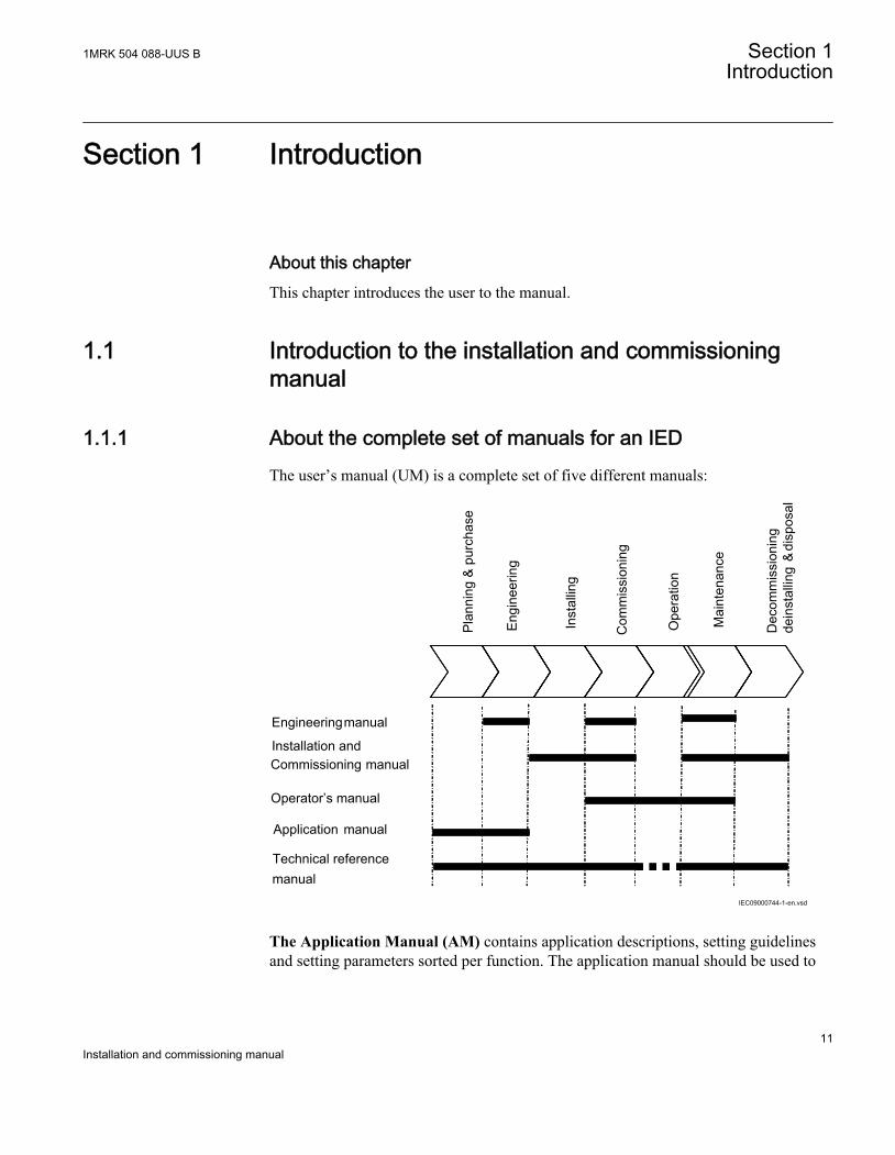
1.1.1 About the complete set of manuals for an IEDThe user’s manual (UM) is a complete set of five different manuals:
IEC09000744-1-en.vsd
Pla
nnin
g &
pur
chas
e
disp
osal
Eng
inee
ring
Inst
allin
g
Com
mis
sion
ing
Ope
ratio
n
Mai
nten
ance
Dec
omm
issi
onin
gde
inst
allin
g&
Application manual
Operator’s manual
Installation and
Engineeringmanual
Commissioning manual
manualTechnical reference
IEC09000744 V1 EN
The Application Manual (AM) contains application descriptions, setting guidelinesand setting parameters sorted per function. The application manual should be used to
1MRK 504 088-UUS B Section 1Introduction
11Installation and commissioning manual
find out when and for what purpose a typical protection function could be used. Themanual should also be used when calculating settings.
The Technical Reference Manual (TRM) contains application and functionalitydescriptions and it lists function blocks, logic diagrams, input and output signals,setting parameters and technical data sorted per function. The technical referencemanual should be used as a technical reference during the engineering phase,installation and commissioning phase, and during normal service.
The Installation and Commissioning Manual (ICM) contains instructions on how toinstall and commission the protection IED. The manual can also be used as a referenceduring periodic testing. The manual covers procedures for mechanical and electricalinstallation, energizing and checking of external circuitry, setting and configuration aswell as verifying settings and performing directional tests. The chapters are organizedin the chronological order (indicated by chapter/section numbers) in which theprotection IED should be installed and commissioned.
The Operator’s Manual (OM) contains instructions on how to operate the protectionIED during normal service once it has been commissioned. The operator’s manual canbe used to find out how to handle disturbances or how to view calculated and measurednetwork data in order to determine the cause of a fault.
The Engineering Manual (EM) contains instructions on how to engineer the IEDsusing the different tools in PCM600. The manual provides instructions on how to setup a PCM600 project and insert IEDs to the project structure. The manual alsorecommends a sequence for engineering of protection and control functions, LHMIfunctions as well as communication engineering for IEC 61850 and DNP3.
1.1.2 About the installation and commissioning manualThe installation and commissioning manual contains the following chapters:
• The chapter Safety information presents warning and note signs, that the usershould pay attention to.
• The chapter Overview is a summary of the major tasks faced when installing andcommissioning an IED.
• The chapter Unpacking and checking the IED explains how to take delivery of theIED.
• The chapter Installing the IED explains how to install the IED.• The chapter Checking the external optical and electrical connections explains how
to check that the IED is properly connected to the protection system.• The chapter Energizing the IED explains how to start the IED.• The chapter Set up PCM 600 communication link per IED describes the
communication between PCM600 and the IED.• The chapter Establishing connection and verifying the SPA/IEC- communication
contains explains how to enter SPA/IEC settings and verifying the communication.
Section 1 1MRK 504 088-UUS BIntroduction
12Installation and commissioning manual
• The chapter Establishing connection and verifying the LON communicationcontains a reference to another document.
• The chapter Establishing connection and verifying the IEC 61850 communicationcontains explains how to enter IEC 61850 settings and verifying the communication.
• The chapter Configuring the IED and changing settings ” explains how to writesettings and configure the IED.
• The chapter Verifying settings by secondary injection contains instructions onhow to verify that each included function operates correctly according to the setvalues.
• The chapter Commissioning and maintenance of the fault clearing systemdiscusses maintenance tests and other periodic maintenance measures.
• The chapter Fault tracing and repair explains how to troubleshoot.• The chapter Glossary is a list of terms, acronyms and abbreviations used in ABB
technical documentation.
1.1.3 Intended audience
GeneralThe installation and commissioning manual addresses the personnel responsible for theinstallation, commissioning, maintenance and taking the protection in and out ofnormal service.
RequirementsThe installation and commissioning personnel must have a basic knowledge inhandling electronic equipment. The commissioning and maintenance personnel mustbe well experienced in using protection equipment, test equipment, protectionfunctions and the configured functional logics in the protection.
1.1.4 Related documentsDocuments related to RET670 Identity numberOperator’s manual 1MRK 504 087-UUS
Installation and commissioning manual 1MRK 504 088-UUS
Technical reference manual 1MRK 504 086-UUS
Application manual 1MRK 504 089-UUS
Buyer’s guide 1MRK 504 091-BUS
Sample specification SA2005-001283
Connection diagram, Two winding transf. Single breaker arrangements 1MRK 002 801-LA
Connection diagram, Two winding transf. Multi breaker arrangements 1MRK 002 801-HA
Connection diagram, Three winding transf. Single breaker arrangements 1MRK 002 801-KA
Table continues on next page
1MRK 504 088-UUS B Section 1Introduction
13Installation and commissioning manual
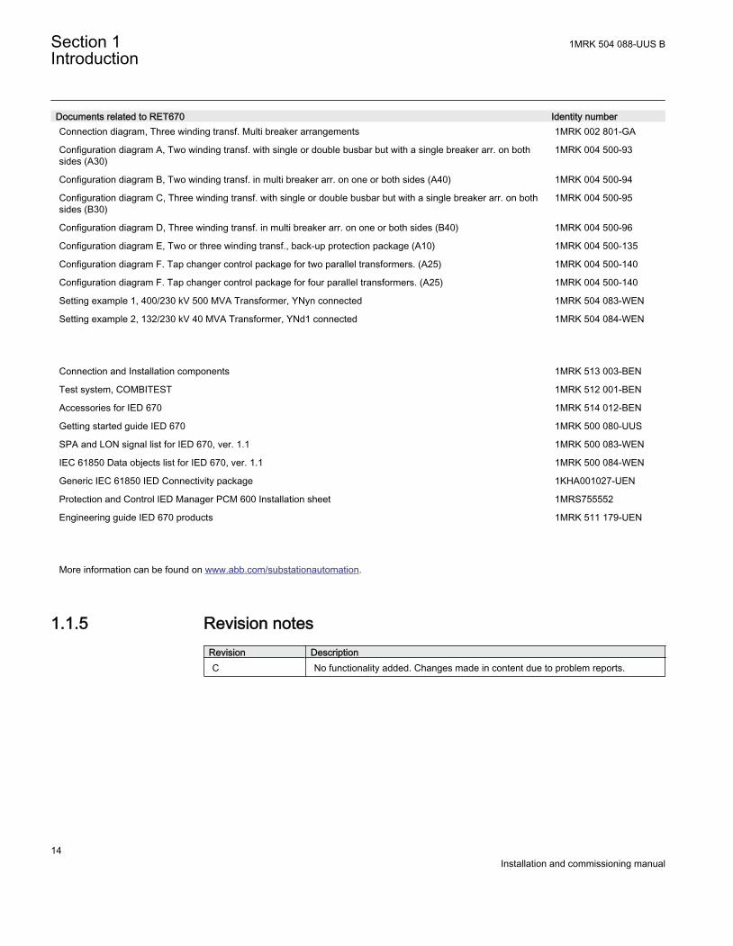
Documents related to RET670 Identity numberConnection diagram, Three winding transf. Multi breaker arrangements 1MRK 002 801-GA
Configuration diagram A, Two winding transf. with single or double busbar but with a single breaker arr. on bothsides (A30)
1MRK 004 500-93
Configuration diagram B, Two winding transf. in multi breaker arr. on one or both sides (A40) 1MRK 004 500-94
Configuration diagram C, Three winding transf. with single or double busbar but with a single breaker arr. on bothsides (B30)
1MRK 004 500-95
Configuration diagram D, Three winding transf. in multi breaker arr. on one or both sides (B40) 1MRK 004 500-96
Configuration diagram E, Two or three winding transf., back-up protection package (A10) 1MRK 004 500-135
Configuration diagram F. Tap changer control package for two parallel transformers. (A25) 1MRK 004 500-140
Configuration diagram F. Tap changer control package for four parallel transformers. (A25) 1MRK 004 500-140
Setting example 1, 400/230 kV 500 MVA Transformer, YNyn connected 1MRK 504 083-WEN
Setting example 2, 132/230 kV 40 MVA Transformer, YNd1 connected 1MRK 504 084-WEN
Connection and Installation components 1MRK 513 003-BEN
Test system, COMBITEST 1MRK 512 001-BEN
Accessories for IED 670 1MRK 514 012-BEN
Getting started guide IED 670 1MRK 500 080-UUS
SPA and LON signal list for IED 670, ver. 1.1 1MRK 500 083-WEN
IEC 61850 Data objects list for IED 670, ver. 1.1 1MRK 500 084-WEN
Generic IEC 61850 IED Connectivity package 1KHA001027-UEN
Protection and Control IED Manager PCM 600 Installation sheet 1MRS755552
Engineering guide IED 670 products 1MRK 511 179-UEN
More information can be found on www.abb.com/substationautomation.
1.1.5 Revision notesRevision DescriptionC No functionality added. Changes made in content due to problem reports.
Section 1 1MRK 504 088-UUS BIntroduction
14Installation and commissioning manual
Section 2 Safety information
About this chapterThis chapter contains safety information. Warning signs are presented which urge theuser to be careful during certain operations in order to avoid injuries to humans ordamage to equipment.
2.1 Warning signs
Strictly follow the company and country safety regulations. Working ina high voltage environment requires serious approach to avoid humaninjuries and damage to equipment.
Do not touch circuitry during operation. Potentially lethal voltages andcurrents are present.
Always avoid touching the circuitry when covers are removed. Theproduct contains electronic circuits which can be damaged if exposed tostatic electricity (ESD). Lethal high voltage circuits are also exposedwhen covers are removed.
Always use suitable isolated test pins when measuring signals in opencircuitry. Potentially lethal voltages and currents are present.
Never connect or disconnect a wire and/or a connector to or from a IEDduring normal operation. Hazardous voltages and currents are presentthat may be lethal. Operation may be disrupted and IED and measuringcircuitry may be damaged.
Always connect the IED to protective ground, regardless of theoperating conditions. This also applies to special occasions such as
1MRK 504 088-UUS B Section 2Safety information
15Installation and commissioning manual
bench testing, demonstrations and off-site configuration. Operating theIED without proper grounding may damage both IED and measuringcircuitry and may cause injuries in case of an accident.
Never disconnect the secondary connection of current transformercircuit without short-circuiting the transformer’s secondary winding.Operating a current transformer with the secondary winding open willcause a massive potential build-up that may damage the transformerand may cause injuries to humans.
Never remove any screw from a powered IED or from a IED connectedto powered circuitry. Potentially lethal voltages and currents are present.
Take adequate measures to protect the eyes. Never look into the laserbeam.
2.2 Caution signs
Always transport PCBs (modules) using certified conductive bags.Always handle modules using a conductive wrist strap connected toprotective ground and on a suitable antistatic surface. Electrostaticdischarge (ESD) may cause damage to the module since electroniccircuits are sensitive to this phenomena.
Do not connect live wires to the IED. Internal circuitry may be damaged
Always use a conductive wrist strap connected to protective groundwhen replacing modules. Electrostatic discharge (ESD) may damagethe module and IED circuitry.
Section 2 1MRK 504 088-UUS BSafety information
16Installation and commissioning manual
Take care to avoid electrical shock if accessing wiring and connectionIEDs when installing and commissioning.
Changing the active setting group will inevitably change the IEDsoperation. Be careful and check regulations before making the change.
2.3 Note signs
The protection assembly is designed for a maximum continuous currentof four times rated value.
1MRK 504 088-UUS B Section 2Safety information
17Installation and commissioning manual

18

Section 3 Overview
About this chapterThis chapter outlines the installation and commissioning of the IED.
3.1 Commissioning and installation overview
The settings for each function must be calculated before the commissioning task canstart. A configuration, done in the configuration and programming tool, must also beavailable if the IED does not have a factory configuration downloaded.
The IED is unpacked and visually checked. It is preferably mounted in a cubicle or ona wall. The connection to the protection system has to be checked in order to verifythat the installation is successful.
1MRK 504 088-UUS B Section 3Overview
19Installation and commissioning manual

20
Section 4 Unpacking and checking the IED
About this chapterThis chapter describes the delivery and the unpacking of the IED
4.1 Taking delivery, unpacking and checking
Procedure
1. Remove the transport casing.2. Visually inspect the IED.3. Check that all items are included in accordance with the delivery documents.
Once the IED has been started make sure that the software functions ordered havebeen included in the delivery.
4. Check for transport damages.If transport damage is discovered appropriate action must be taken against thelatest carrier and the nearest ABB office or representative should be informed.ABB should be notified immediately if there are any discrepancies in relation tothe delivery documents.
5. StorageIf the IED is to be stored before installation, this must be done in the originaltransport casing in a dry and dust free place. Observe the environmentalrequirements stated in the technical data.
1MRK 504 088-UUS B Section 4Unpacking and checking the IED
21Installation and commissioning manual

22

Section 5 Installing the IED
About this chapterThis chapter describes how to install the IED.
5.1 Overview
The mechanical and electrical environmental conditions at the installation site must bewithin the limits described in the IED technical data. Dusty, damp places, placessusceptible to rapid temperature variations, powerful vibrations and shocks, surgevoltages of high amplitude and fast rise time, strong induced magnetic fields or similarextreme conditions should be avoided.
Sufficient space must be available in front of and at the rear of the IED to allow accessfor maintenance and future modifications. Flush mounted IEDs should be mounted sothat IED modules can be added and replaced without excessive dismantling.
1MRK 504 088-UUS B Section 5Installing the IED
23Installation and commissioning manual
5.2 Dimensions
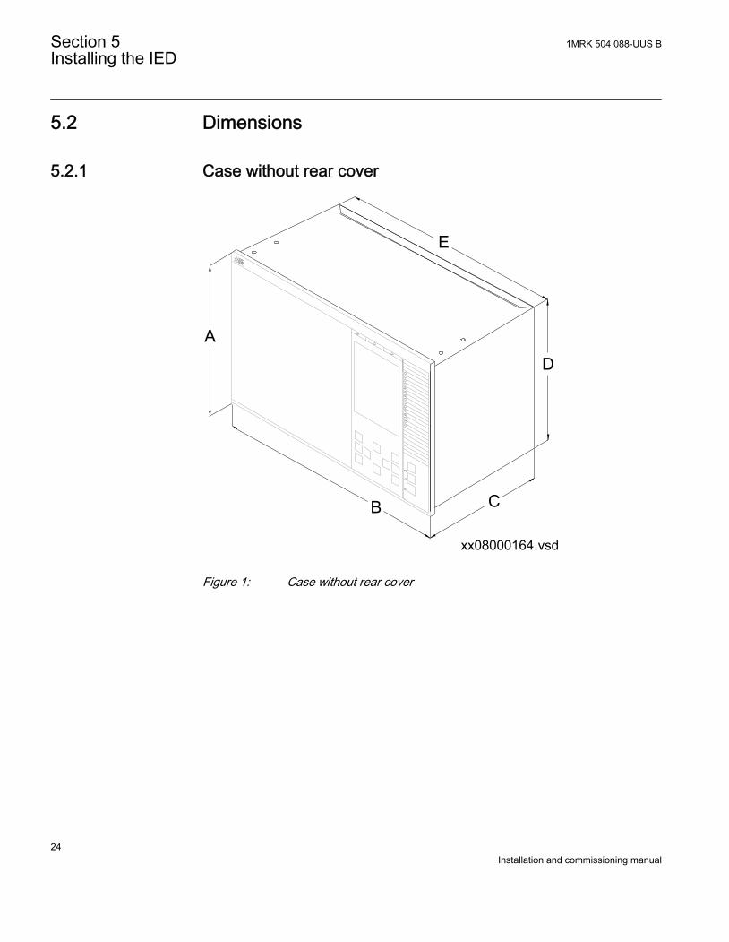
5.2.1 Case without rear cover
xx08000164.vsd
CB
D
E
A
IEC08000164 V1 EN
Figure 1: Case without rear cover
Section 5 1MRK 504 088-UUS BInstalling the IED
24Installation and commissioning manual
xx08000166.vsd
JG
F
K
H
IEC08000166 V1 EN
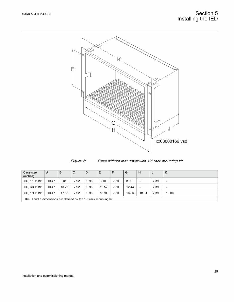
Figure 2: Case without rear cover with 19” rack mounting kit
Case size(inches)
A B C D E F G H J K
6U, 1/2 x 19” 10.47 8.81 7.92 9.96 8.10 7.50 8.02 - 7.39 -
6U, 3/4 x 19” 10.47 13.23 7.92 9.96 12.52 7.50 12.44 - 7.39 -
6U, 1/1 x 19” 10.47 17.65 7.92 9.96 16.94 7.50 16.86 18.31 7.39 19.00
The H and K dimensions are defined by the 19” rack mounting kit
1MRK 504 088-UUS B Section 5Installing the IED
25Installation and commissioning manual
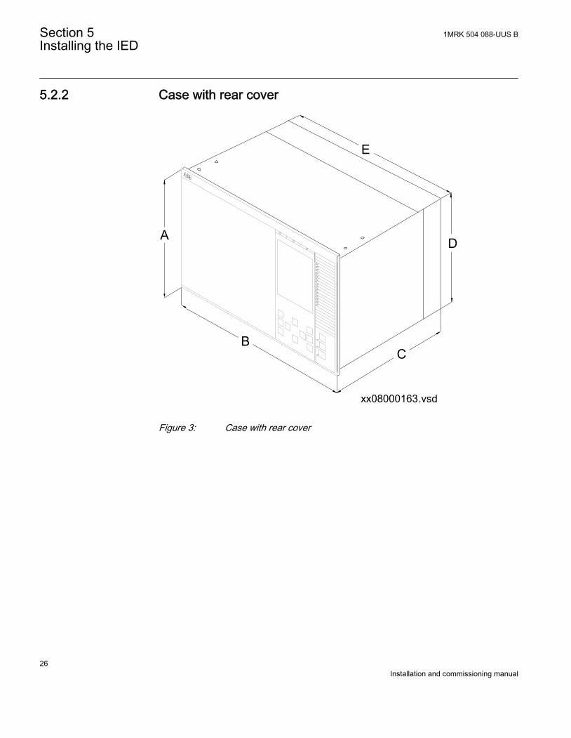
5.2.2 Case with rear cover
xx08000163.vsd
CB
D
E
A
IEC08000163 V1 EN
Figure 3: Case with rear cover
Section 5 1MRK 504 088-UUS BInstalling the IED
26Installation and commissioning manual
xx08000165.vsd
JG
F
K
H
IEC08000165 V1 EN
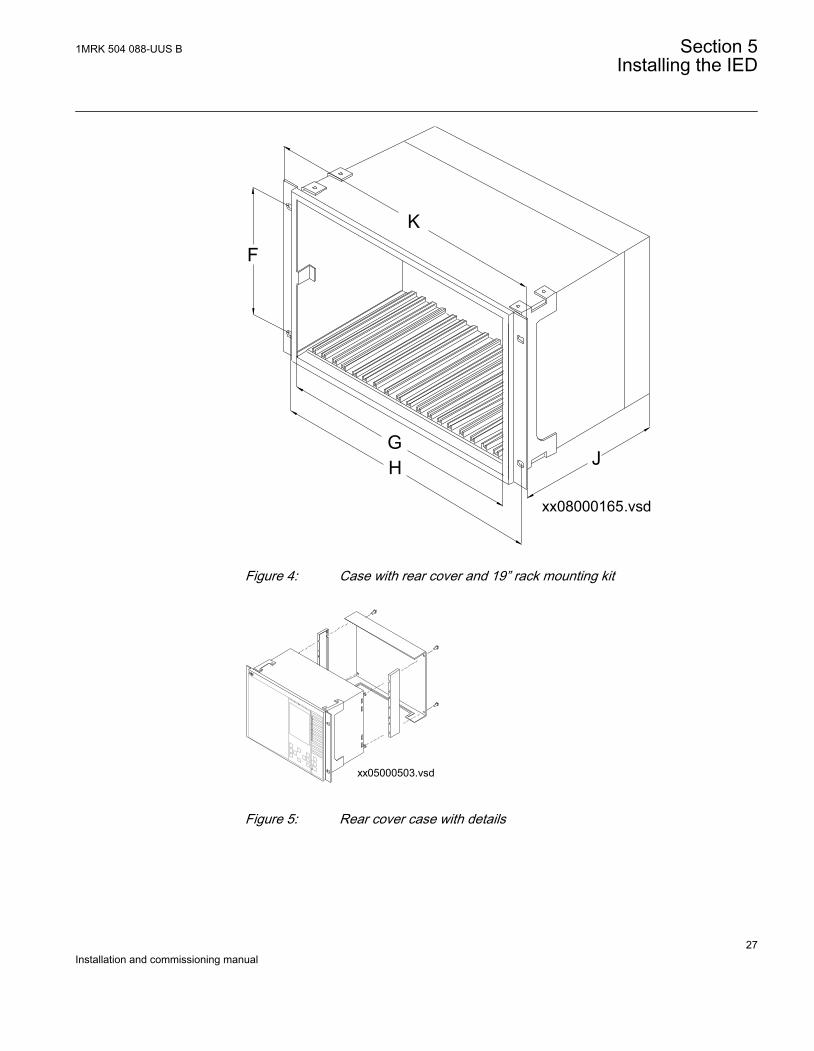
Figure 4: Case with rear cover and 19” rack mounting kit
xx05000503.vsd
IEC05000503 V1 EN
Figure 5: Rear cover case with details
1MRK 504 088-UUS B Section 5Installing the IED
27Installation and commissioning manual
Case size(inches)
A B C D E F G H J K
6U, 1/2 x 19” 10.47 8.81 9.53 10.07 8.10 7.50 8.02 - 9.00 -
6U, 3/4 x 19” 10.47 13.23 9.53 10.07 12.52 7.50 12.4 - 9.00 -
6U, 1/1 x 19” 10.47 17.65 9.53 10.07 16.86 7.50 16.86 18.31 9.00 19.00
The H and K dimensions are defined by the 19” rack mounting kit.
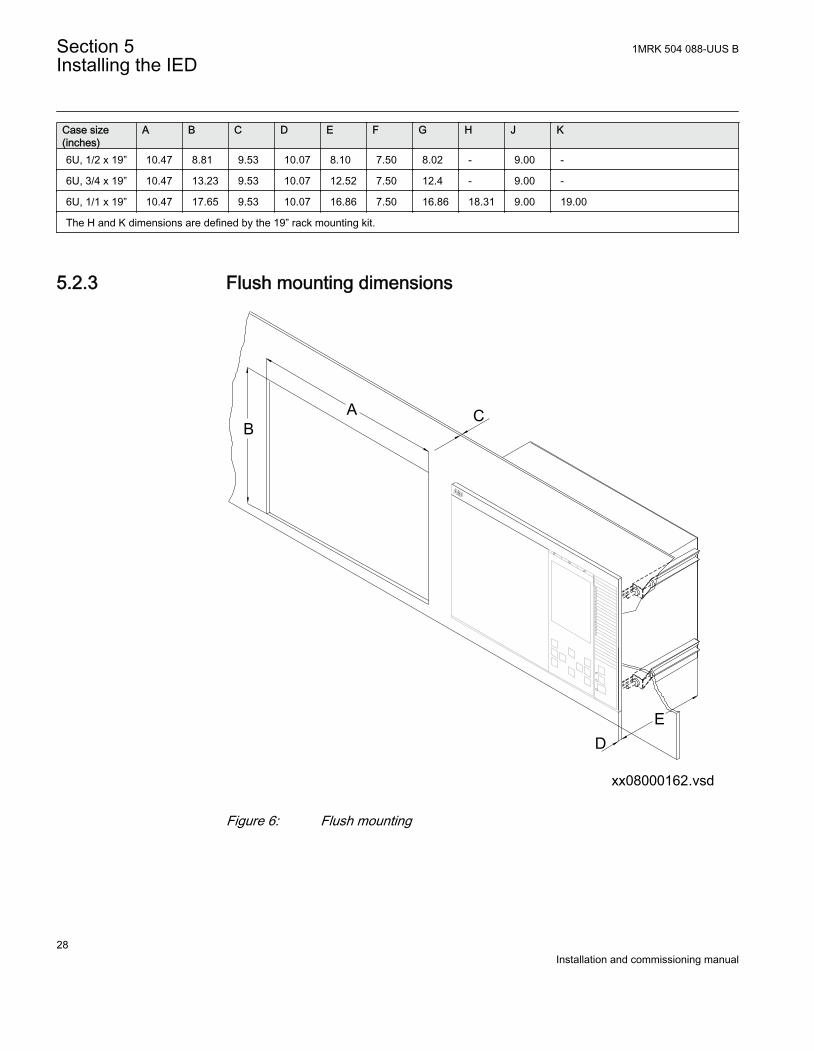
5.2.3 Flush mounting dimensions
CAB
ED
xx08000162.vsdIEC08000162 V1 EN
Figure 6: Flush mounting
Section 5 1MRK 504 088-UUS BInstalling the IED
28Installation and commissioning manual

Case sizeTolerance
Cut-out dimensions (inches)
A+/0.04
B+/0.04
C D
6U, 1/2 x 19” 8.27 10.01 0.16–0.39 0.49
6U, 3/4 x 19” 12.69 10.01 0.16–0.39 0.49
6U, 1/1 x 19” 17.11 10.01 0.16–0.39 0.49
E = 188.6 mm without rear protection cover, 229.6 mm with rear protection cover
5.2.4 Side-by-side flush mounting dimensions
xx06000182.vsd
IEC06000182 V1 EN
Figure 7: A 1/2 x 19” size 670 series IED side-by-side with RHGS6.
1MRK 504 088-UUS B Section 5Installing the IED
29Installation and commissioning manual
xx05000505.vsd
B
A
C
G
D
E
F
IEC05000505 V1 EN
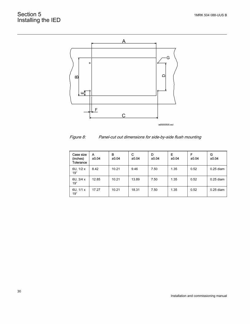
Figure 8: Panel-cut out dimensions for side-by-side flush mounting
Case size(inches)Tolerance
A±0.04
B±0.04
C±0.04
D±0.04
E±0.04
F±0.04
G±0.04
6U, 1/2 x19”
8.42 10.21 9.46 7.50 1.35 0.52 0.25 diam
6U, 3/4 x19”
12.85 10.21 13.89 7.50 1.35 0.52 0.25 diam
6U, 1/1 x19”
17.27 10.21 18.31 7.50 1.35 0.52 0.25 diam
Section 5 1MRK 504 088-UUS BInstalling the IED
30Installation and commissioning manual
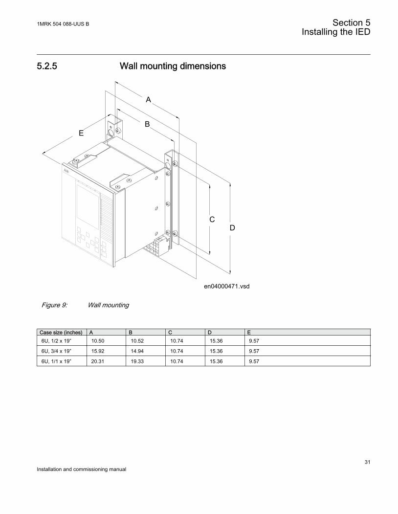
5.2.5 Wall mounting dimensions
en04000471.vsd
E
A
B
CD
IEC04000471 V1 EN
Figure 9: Wall mounting
Case size (inches) A B C D E6U, 1/2 x 19” 10.50 10.52 10.74 15.36 9.57
6U, 3/4 x 19” 15.92 14.94 10.74 15.36 9.57
6U, 1/1 x 19” 20.31 19.33 10.74 15.36 9.57
1MRK 504 088-UUS B Section 5Installing the IED
31Installation and commissioning manual
5.3 Mounting methods and details
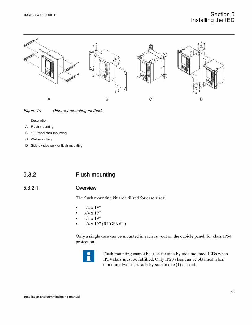
5.3.1 Mounting the IEDThe IED can be rack, wall or flush mounted with the use of different mounting kits, seefigure 10.
An additional box of type RHGS can be mounted to one side of a 1/2 or 3/4 IED.
The different mounting kits contain all parts needed including screws and assemblyinstructions. The following mounting kits are available:
• Flush mounting kit• 19” Panel (rack) mounting kit• Wall mounting kit• Side-by-side mounting kit
The same mounting kit is used for side-by-side rack mounting and side-by-side flushmounting.
The mounting kits must be ordered separately when ordering an IED.They are available as options on the ordering sheet in Accessories for670 series IED, see section "Related documents".
IEC02000684V1 EN
Generally, all the screws included in delivered mounting kits are of Torx type and ascrewdriver of the same type is needed (Tx10, Tx15, Tx20 and Tx25).
If other type of screws are to be used, be sure to use the dimensions ofthe screws that are given in this guide.
Section 5 1MRK 504 088-UUS BInstalling the IED
32Installation and commissioning manual
A B C DIEC06000147 V1 EN
Figure 10: Different mounting methods
Description
A Flush mounting
B 19” Panel rack mounting
C Wall mounting
D Side-by-side rack or flush mounting
5.3.2 Flush mounting
5.3.2.1 Overview
The flush mounting kit are utilized for case sizes:
• 1/2 x 19”• 3/4 x 19”• 1/1 x 19”• 1/4 x 19” (RHGS6 6U)
Only a single case can be mounted in each cut-out on the cubicle panel, for class IP54protection.
Flush mounting cannot be used for side-by-side mounted IEDs whenIP54 class must be fulfilled. Only IP20 class can be obtained whenmounting two cases side-by-side in one (1) cut-out.
1MRK 504 088-UUS B Section 5Installing the IED
33Installation and commissioning manual

To obtain IP54 class protection, an additional factory mounted sealingmust be ordered when ordering the IED.
Section 5 1MRK 504 088-UUS BInstalling the IED
34Installation and commissioning manual
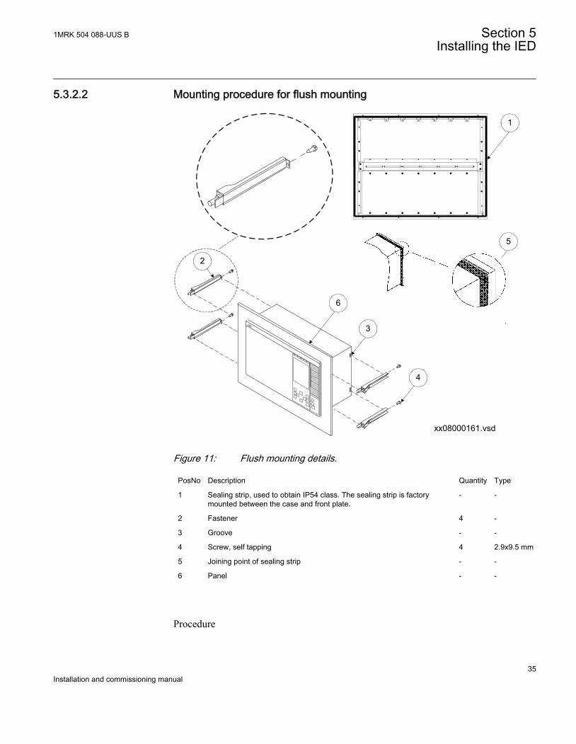
5.3.2.2 Mounting procedure for flush mounting
1
3
5
xx08000161.vsd
4
2
6
IEC08000161 V1 EN
Figure 11: Flush mounting details.
PosNo Description Quantity Type
1 Sealing strip, used to obtain IP54 class. The sealing strip is factorymounted between the case and front plate.
- -
2 Fastener 4 -
3 Groove - -
4 Screw, self tapping 4 2.9x9.5 mm
5 Joining point of sealing strip - -
6 Panel - -
Procedure
1MRK 504 088-UUS B Section 5Installing the IED
35Installation and commissioning manual
1. Cut an opening in the panel (6).See section "Flush mounting dimensions" regarding dimensions.
2. Carefully press the sealing strip (1) around the IEDs collar. Cut the end of thesealing strip a few mm to long to make the joining point (5) tight.The sealing strip is delivered with the mounting kit. The strip is long enough forthe largest available IED.
3. Insert the IED into the opening (cut-out) in the panel.4. Add and lock the fasteners (2) to the IED.
Thread a fastener into the groove at the back end of the IED. Insert and lightlyfasten the locking screw (4). Next, thread a fastener on the other side of the IED,and lightly fasten its locking screw. Lock the front end of the fastener in thepanel, using the M5x25 screws.Repeat the procedure with the remaining two fasteners.
5.3.3 19” panel rack mounting
5.3.3.1 Overview
All IED sizes can be mounted in a standard 19” cubicle rack by using the for each sizesuited mounting kit which consists of two mounting angles and fastening screws forthe angles.
The mounting angles are reversible which enables mounting of IED size 1/2 x 19” or3/4 x 19” either to the left or right side of the cubicle.
Please note that the separately ordered rack mounting kit for side-by-side mounted IEDs, or IEDs together with RHGS cases, is to beselected so that the total size equals 19”.
When mounting the mounting angles, be sure to use screws that followsthe recommended dimensions. Using screws with other dimensionsthan the original may damage the PCBs inside the IED.
Section 5 1MRK 504 088-UUS BInstalling the IED
36Installation and commissioning manual
5.3.3.2 Mounting procedure for 19” panel rack mounting
xx08000160.vsd
1a
2
1b
IEC08000160 V1 EN
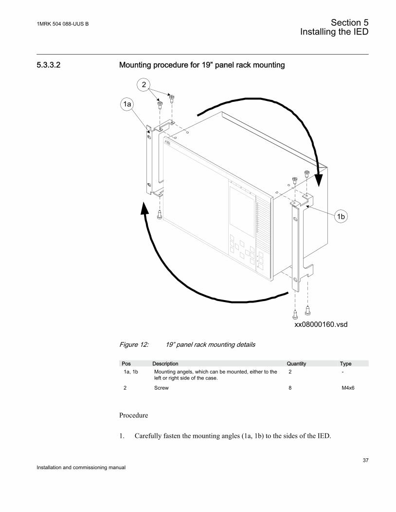
Figure 12: 19” panel rack mounting details
Pos Description Quantity Type1a, 1b Mounting angels, which can be mounted, either to the
left or right side of the case.2 -
2 Screw 8 M4x6
Procedure
1. Carefully fasten the mounting angles (1a, 1b) to the sides of the IED.
1MRK 504 088-UUS B Section 5Installing the IED
37Installation and commissioning manual
Use the screws (2) supplied in the mounting kit.2. Place the IED assembly in the 19” panel.3. Fasten the mounting angles with appropriate screws.
5.3.4 Wall mounting
5.3.4.1 Overview
All case sizes, 1/2 x 19”, 3/4 x 19” and 1/1 x 19”, can be wall mounted. It is alsopossible to mount the IED on a panel or in a cubicle.
When mounting the side plates, be sure to use screws that follows therecommended dimensions. Using screws with other dimensions thanthe original may damage the PCBs inside the IED.
If fiber cables are bent too much, the signal can be weakened. Wallmounting is therefore not recommended for communication moduleswith fiber connection; Serial SPA/IEC 60870-5-103 and LONcommunication module (SLM), Optical Ethernet module (OEM) andLine data communication module (LDCM).
Section 5 1MRK 504 088-UUS BInstalling the IED
38Installation and commissioning manual

5.3.4.2 Mounting procedure for wall mounting
xx04000453.vsd
1
2
3
4
5
6
DOCUMENT127716-IMG2265 V1 EN
Figure 13: Wall mounting details.
PosNo Description Quantity Type
1 Bushing 4 -
2 Screw 8 M4x10
3 Screw 4 M6x12 or corresponding
4 Mounting bar 2 -
5 Screw 6 M5x8
6 Side plate 2 -
Procedure
1. Mount the mounting bars onto the wall (4).See section "Wall mounting dimensions" for mounting dimensions.Depending on the wall different preparations may be needed like drilling andinserting plastic or expander plugs (concrete/plasterboard walls) or threading(metal sheet wall).
2. Make all electrical connections to the IED terminal.
1MRK 504 088-UUS B Section 5Installing the IED
39Installation and commissioning manual

It is much easier to do this without the unit in place.3. Mount the side plates to the IED.4. Mount the IED to the mounting bars.
5.3.4.3 How to reach the rear side of the IED
The IED can be equipped with a rear protection cover, which is recommended to usewith this type of mounting. See figure 14.
To reach the rear side of the IED, a free space of 3.2 inches is required on the unhingedside.
3.2"
View from above
1
ANSI_en06000135.vsd
3
2(80 mm)
ANSI06000135 V1 EN
Figure 14: How to reach the connectors on the rear side of the IED.
PosNo Description Type
1 Screw M4x10
2 Screw M5x8
3 Rear protection cover -
Procedure
1. Remove the inner screws (1), upper and lower on one side.2. Remove all three fixing screws (2), on the opposite side, from wall support.3. The IED can now be swung out for access to the connectors, after removing any
rear protection.
Section 5 1MRK 504 088-UUS BInstalling the IED
40Installation and commissioning manual
5.3.5 Side-by-side 19” rack mounting
5.3.5.1 Overview
IED case sizes, 1/2 x 19” or 3/4 x 19” and RHGS cases, can be mounted side-by-sideup to a maximum size of 19”. For side-by-side rack mounting, the side-by-sidemounting kit together with the 19” rack panel mounting kit must be used. Themounting kit has to be ordered separately.
When mounting the plates and the angles on the IED, be sure to usescrews that follows the recommended dimensions. Using screws withother dimensions than the original may damage the PCBs inside the IED.
5.3.5.2 Mounting procedure for side-by-side rack mounting
xx04000456.vsd
3
4
1
2
IEC04000456 V1 EN
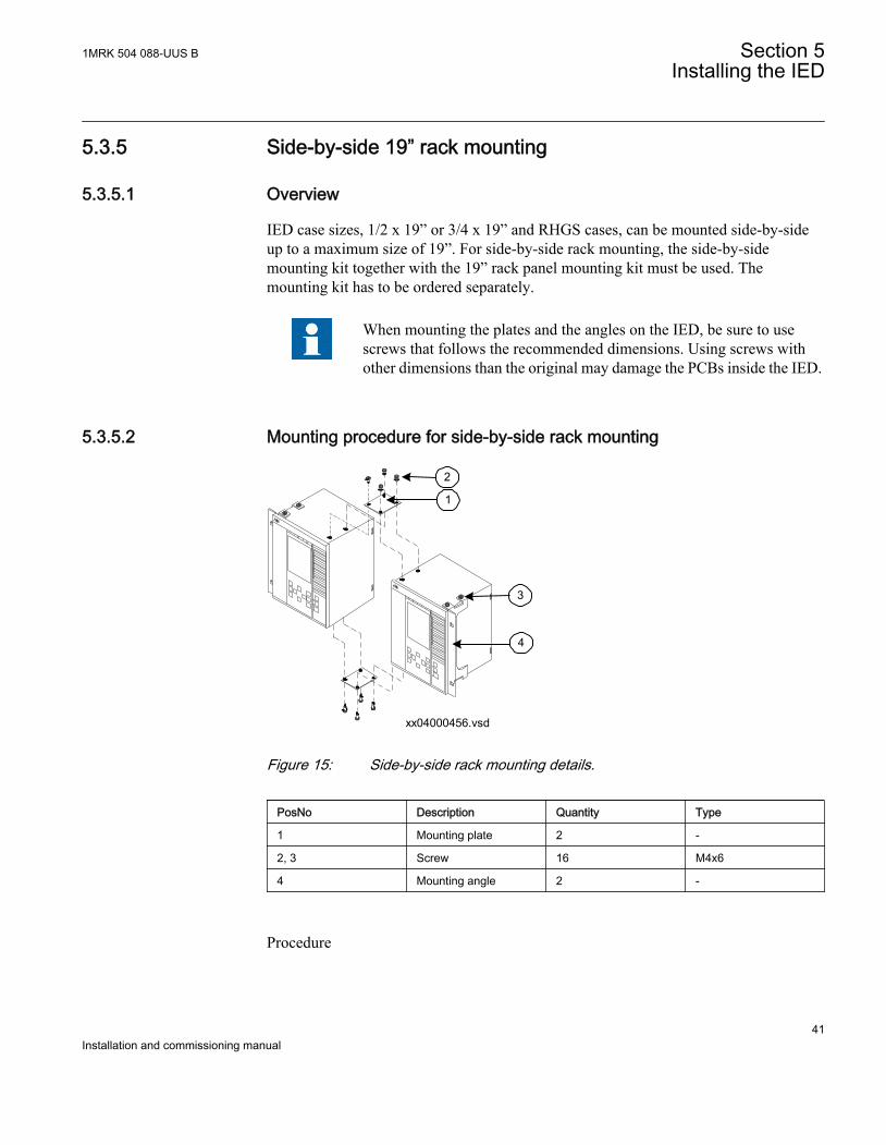
Figure 15: Side-by-side rack mounting details.
PosNo Description Quantity Type
1 Mounting plate 2 -
2, 3 Screw 16 M4x6
4 Mounting angle 2 -
Procedure
1MRK 504 088-UUS B Section 5Installing the IED
41Installation and commissioning manual
1. Place the two IEDs next to each other on a flat surface.2. Fasten a side-by-side mounting plate (1).
Use four of the delivered screws (2, 3).3. Carefully turn the two IEDs up-side down.4. Fasten the second side-by-side mounting plate.
Use the remaining four screws.5. Carefully fasten the mounting angles (4) to the sides of the IED.
Use the screws available in the mounting kit.6. Place the IED assembly in the rack.7. Fasten the mounting angles with appropriate screws.
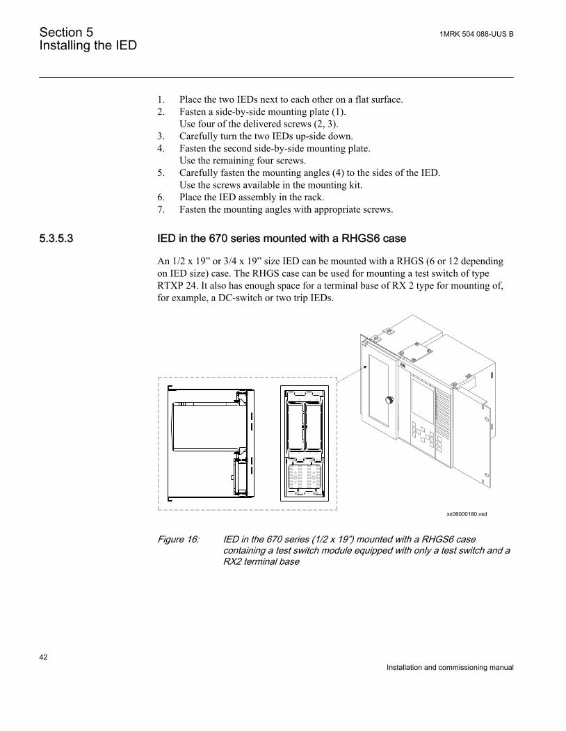
5.3.5.3 IED in the 670 series mounted with a RHGS6 case
An 1/2 x 19” or 3/4 x 19” size IED can be mounted with a RHGS (6 or 12 dependingon IED size) case. The RHGS case can be used for mounting a test switch of typeRTXP 24. It also has enough space for a terminal base of RX 2 type for mounting of,for example, a DC-switch or two trip IEDs.
xx06000180.vsd
8 88
7
5
6
3
4
2
7
5
6
7
5
6
3
4
2
3
4
2
1
1
1
2
1 1
1
8
7
5
6
3
4
2
2
2
1
IEC06000180 V1 EN
Figure 16: IED in the 670 series (1/2 x 19”) mounted with a RHGS6 casecontaining a test switch module equipped with only a test switch and aRX2 terminal base
Section 5 1MRK 504 088-UUS BInstalling the IED
42Installation and commissioning manual
5.3.6 Side-by-side flush mounting
5.3.6.1 Overview
It is not recommended to flush mount side by side mounted cases if IP54 is required. Ifyour application demands side-by-side flush mounting, the side-by-side mountingdetails kit and the 19” panel rack mounting kit must be used. The mounting kit has tobe ordered separately. The maximum size of the panel cut out is 19”.
With side-by-side flush mounting installation, only IP class 20 isobtained. To reach IP class 54, it is recommended to mount the IEDsseparately. For cut out dimensions of separately mounted IEDs, seesection "Flush mounting".
When mounting the plates and the angles on the IED, be sure to usescrews that follows the recommended dimensions. Using screws withother dimensions than the original may damage the PCBs inside the IED.
Please contact factory for special add on plates for mounting FTswitches on the side (for 1/2 19" case) or bottom of the relay.
1MRK 504 088-UUS B Section 5Installing the IED
43Installation and commissioning manual
5.3.6.2 Mounting procedure for side-by-side flush mounting
xx06000181.vsd
1 2
3
4
IEC06000181 V1 EN
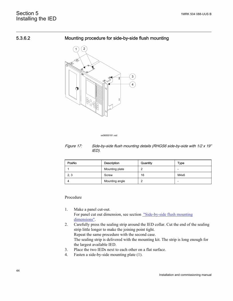
Figure 17: Side-by-side flush mounting details (RHGS6 side-by-side with 1/2 x 19”IED).
PosNo Description Quantity Type
1 Mounting plate 2 -
2, 3 Screw 16 M4x6
4 Mounting angle 2 -
Procedure
1. Make a panel cut-out.For panel cut out dimension, see section "Side-by-side flush mountingdimensions".
2. Carefully press the sealing strip around the IED collar. Cut the end of the sealingstrip little longer to make the joining point tight.Repeat the same procedure with the second case.The sealing strip is delivered with the mounting kit. The strip is long enough forthe largest available IED.
3. Place the two IEDs next to each other on a flat surface.4. Fasten a side-by-side mounting plate (1).
Section 5 1MRK 504 088-UUS BInstalling the IED
44Installation and commissioning manual
Use four of the delivered screws (2, 3).5. Carefully turn the two IEDs up-side down.6. Fasten the second side-by-side mounting plate.
Use the remaining four screws.7. Carefully fasten the mounting angles (4) to the sides of the IED.
Use the fixing screws available in the mounting kit.8. Insert the IED into the cut-out.9. Fasten the mounting angles with appropriate screws.
5.4 Making the electrical connection
5.4.1 IED connectors
5.4.1.1 Overview
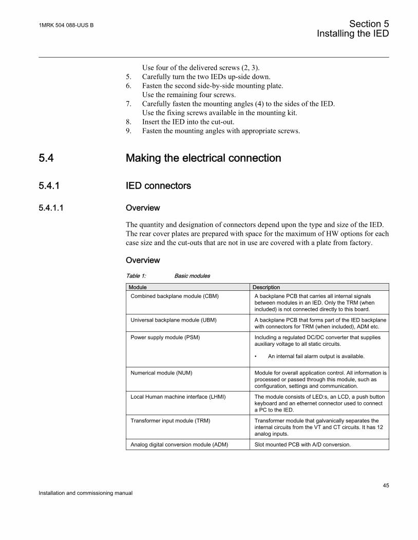
The quantity and designation of connectors depend upon the type and size of the IED.The rear cover plates are prepared with space for the maximum of HW options for eachcase size and the cut-outs that are not in use are covered with a plate from factory.
Overview
Table 1: Basic modules
Module DescriptionCombined backplane module (CBM) A backplane PCB that carries all internal signals
between modules in an IED. Only the TRM (whenincluded) is not connected directly to this board.
Universal backplane module (UBM) A backplane PCB that forms part of the IED backplanewith connectors for TRM (when included), ADM etc.
Power supply module (PSM) Including a regulated DC/DC converter that suppliesauxiliary voltage to all static circuits.
• An internal fail alarm output is available.
Numerical module (NUM) Module for overall application control. All information isprocessed or passed through this module, such asconfiguration, settings and communication.
Local Human machine interface (LHMI) The module consists of LED:s, an LCD, a push buttonkeyboard and an ethernet connector used to connecta PC to the IED.
Transformer input module (TRM) Transformer module that galvanically separates theinternal circuits from the VT and CT circuits. It has 12analog inputs.
Analog digital conversion module (ADM) Slot mounted PCB with A/D conversion.
1MRK 504 088-UUS B Section 5Installing the IED
45Installation and commissioning manual
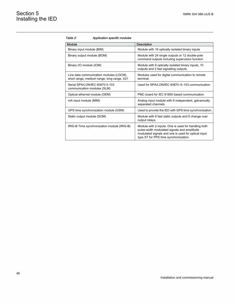
Table 2: Application specific modules
Module DescriptionBinary input module (BIM) Module with 16 optically isolated binary inputs
Binary output module (BOM) Module with 24 single outputs or 12 double-polecommand outputs including supervision function
Binary I/O module (IOM) Module with 8 optically isolated binary inputs, 10outputs and 2 fast signalling outputs.
Line data communication modules (LDCM),short range, medium range, long range, X21
Modules used for digital communication to remoteterminal.
Serial SPA/LON/IEC 60870-5-103communication modules (SLM)
Used for SPA/LON/IEC 60870–5–103 communication
Optical ethernet module (OEM) PMC board for IEC 61850 based communication.
mA input module (MIM) Analog input module with 6 independent, galvanicallyseparated channels.
GPS time synchronization module (GSM) Used to provide the IED with GPS time synchronization.
Static output module (SOM) Module with 6 fast static outputs and 6 change overoutput relays.
IRIG-B Time synchronization module (IRIG-B) Module with 2 inputs. One is used for handling bothpulse-width modulated signals and amplitudemodulated signals and one is used for optical inputtype ST for PPS time synchronization.
Section 5 1MRK 504 088-UUS BInstalling the IED
46Installation and commissioning manual
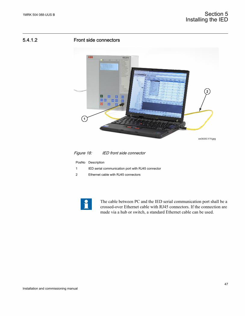
5.4.1.2 Front side connectors
IEC06000179 V1 EN
Figure 18: IED front side connector
PosNo Description
1 IED serial communication port with RJ45 connector
2 Ethernet cable with RJ45 connectors
The cable between PC and the IED serial communication port shall be acrossed-over Ethernet cable with RJ45 connectors. If the connection aremade via a hub or switch, a standard Ethernet cable can be used.
1MRK 504 088-UUS B Section 5Installing the IED
47Installation and commissioning manual
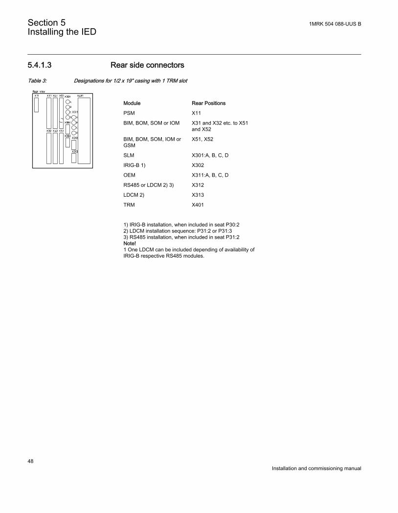
5.4.1.3 Rear side connectors
Table 3: Designations for 1/2 x 19” casing with 1 TRM slot
IEC08000486 BG V1 EN
Module Rear Positions
PSM X11
BIM, BOM, SOM or IOM X31 and X32 etc. to X51and X52
BIM, BOM, SOM, IOM orGSM
X51, X52
SLM X301:A, B, C, D
IRIG-B 1) X302
OEM X311:A, B, C, D
RS485 or LDCM 2) 3) X312
LDCM 2) X313
TRM X401
1) IRIG-B installation, when included in seat P30:22) LDCM installation sequence: P31:2 or P31:33) RS485 installation, when included in seat P31:2Note!1 One LDCM can be included depending of availability ofIRIG-B respective RS485 modules.
Section 5 1MRK 504 088-UUS BInstalling the IED
48Installation and commissioning manual
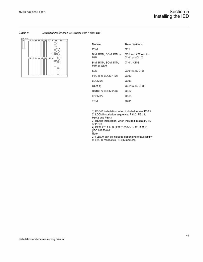
Table 4: Designations for 3/4 x 19” casing with 1 TRM slot
IEC08000487 BG V1 EN
Module Rear Positions
PSM X11
BIM, BOM, SOM, IOM orMIM
X31 and X32 etc. toX101 and X102
BIM, BOM, SOM, IOM,MIM or GSM
X101, X102
SLM X301:A, B, C, D
IRIG-B or LDCM 1) 2) X302
LDCM 2) X303
OEM 4) X311:A, B, C, D
RS485 or LDCM 2) 3) X312
LDCM 2) X313
TRM X401
1) IRIG-B installation, when included in seat P30:22) LDCM installation sequence: P31:2, P31:3,P30:2 and P30:33) RS485 installation, when included in seat P31:2or P31:34) OEM X311:A, B (IEC 61850-8-1). X311:C, D(IEC 61850-8-1Note!2-4 LDCM can be included depending of availabilityof IRIG-B respective RS485 modules.
1MRK 504 088-UUS B Section 5Installing the IED
49Installation and commissioning manual
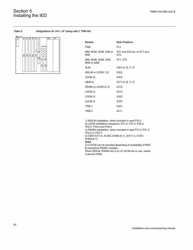
Table 5: Designations for 3/4 x 19” casing with 2 TRM slot
IEC08000488 BG V1 EN
Module Rear Positions
PSM X11
BIM, BOM, SOM, IOM orMIM
X31 and X32 etc. to X71 andX72
BIM, BOM, SOM, IOM,MIM or GSM
X71, X72
SLM X301:A, B, C, D
IRIG-B or LDCM 1,2) X302
LDCM 2) X303
OEM 4) X311:A, B, C, D
RS485 or LDCM 2) 3) X312
LDCM 2) X313
LDCM 2) X322
LDCM 2) X323
TRM 1 X401
TRM 2 X411
1) IRIG-B installation, when included in seat P30:22) LDCM installation sequence: P31:2, P31:3, P32:2,P32:3, P30:2 and P30:33) RS485 installation, when included in seat P31:2, P31:3,P32:2 or P32:34) OEM X311:A, B (IEC 61850-8-1). (X311:C, D IEC61850-8-1)Note!2-4 LDCM can be included depending of availability of IRIG-B respective RS485 modules.When IRIG-B, RS485 and 4 pc of LDCM are in use, needsa second ADM.
Section 5 1MRK 504 088-UUS BInstalling the IED
50Installation and commissioning manual
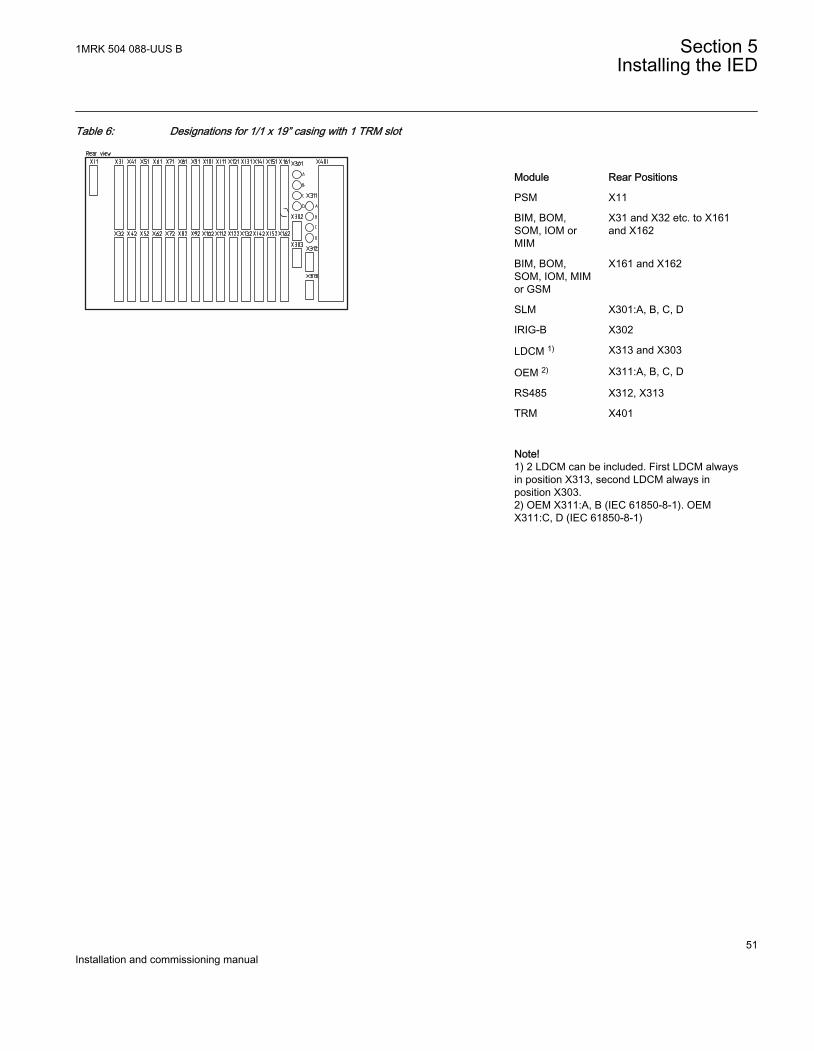
Table 6: Designations for 1/1 x 19” casing with 1 TRM slot
IEC08000489 BG V1 EN
Module Rear Positions
PSM X11
BIM, BOM,SOM, IOM orMIM
X31 and X32 etc. to X161and X162
BIM, BOM,SOM, IOM, MIMor GSM
X161 and X162
SLM X301:A, B, C, D
IRIG-B X302
LDCM 1) X313 and X303
OEM 2) X311:A, B, C, D
RS485 X312, X313
TRM X401
Note!1) 2 LDCM can be included. First LDCM alwaysin position X313, second LDCM always inposition X303.2) OEM X311:A, B (IEC 61850-8-1). OEMX311:C, D (IEC 61850-8-1)
1MRK 504 088-UUS B Section 5Installing the IED
51Installation and commissioning manual
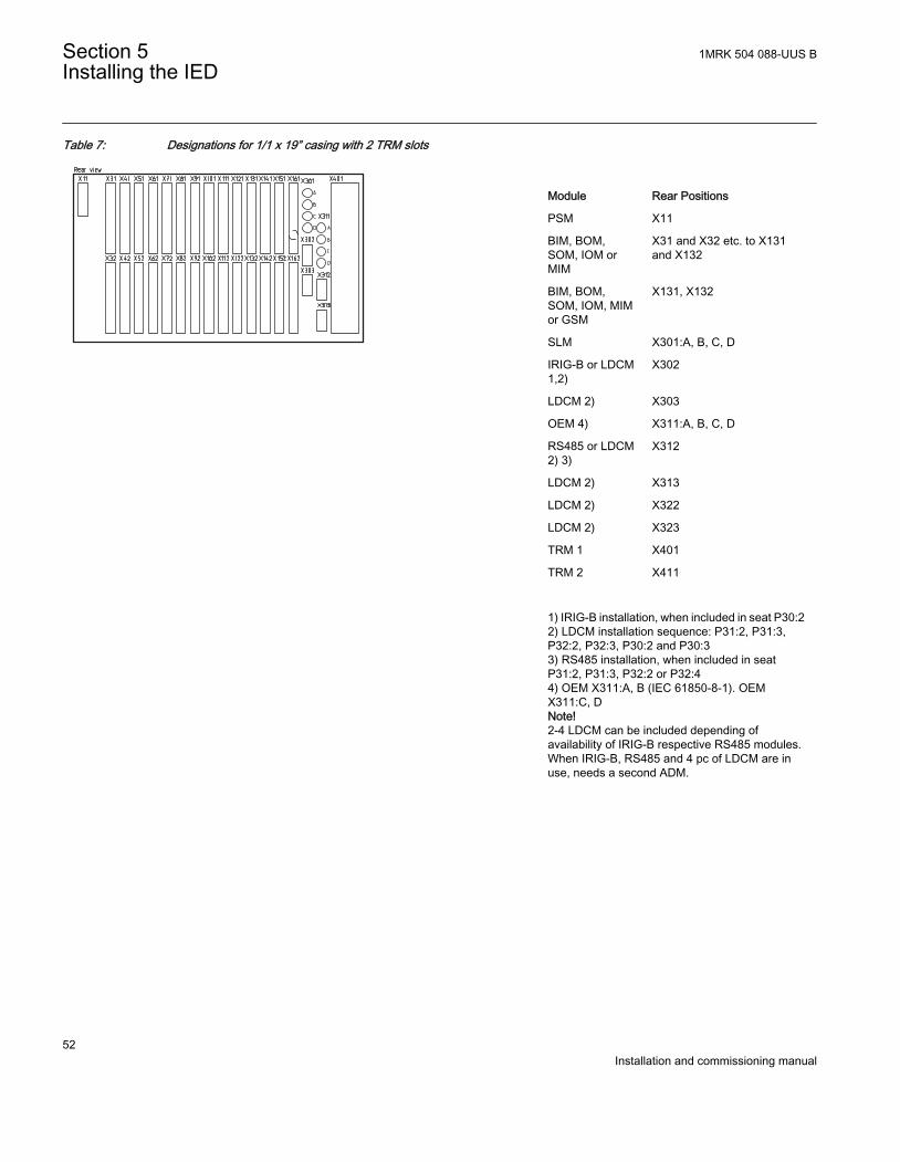
Table 7: Designations for 1/1 x 19” casing with 2 TRM slots
IEC08000489 BG V1 EN
Module Rear Positions
PSM X11
BIM, BOM,SOM, IOM orMIM
X31 and X32 etc. to X131and X132
BIM, BOM,SOM, IOM, MIMor GSM
X131, X132
SLM X301:A, B, C, D
IRIG-B or LDCM1,2)
X302
LDCM 2) X303
OEM 4) X311:A, B, C, D
RS485 or LDCM2) 3)
X312
LDCM 2) X313
LDCM 2) X322
LDCM 2) X323
TRM 1 X401
TRM 2 X411
1) IRIG-B installation, when included in seat P30:22) LDCM installation sequence: P31:2, P31:3,P32:2, P32:3, P30:2 and P30:33) RS485 installation, when included in seatP31:2, P31:3, P32:2 or P32:44) OEM X311:A, B (IEC 61850-8-1). OEMX311:C, DNote!2-4 LDCM can be included depending ofavailability of IRIG-B respective RS485 modules.When IRIG-B, RS485 and 4 pc of LDCM are inuse, needs a second ADM.
Section 5 1MRK 504 088-UUS BInstalling the IED
52Installation and commissioning manual
IEC08000479 BG V1 EN
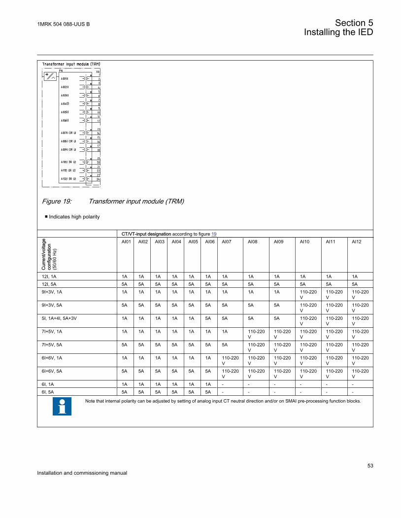
Figure 19: Transformer input module (TRM)
■ Indicates high polarity
CT/VT-input designation according to figure 19
Cur
rent
/vol
tage
conf
igur
atio
n(5
0/60
Hz)
AI01 AI02 AI03 AI04 AI05 AI06 AI07 AI08 AI09 AI10 AI11 AI12
12I, 1A 1A 1A 1A 1A 1A 1A 1A 1A 1A 1A 1A 1A12I, 5A 5A 5A 5A 5A 5A 5A 5A 5A 5A 5A 5A 5A9I+3V, 1A 1A 1A 1A 1A 1A 1A 1A 1A 1A 110-220
V110-220V
110-220V
9I+3V, 5A 5A 5A 5A 5A 5A 5A 5A 5A 5A 110-220V
110-220V
110-220V
5I, 1A+4I, 5A+3V 1A 1A 1A 1A 1A 5A 5A 5A 5A 110-220V
110-220V
110-220V
7I+5V, 1A 1A 1A 1A 1A 1A 1A 1A 110-220V
110-220V
110-220V
110-220V
110-220V
7I+5V, 5A 5A 5A 5A 5A 5A 5A 5A 110-220V
110-220V
110-220V
110-220V
110-220V
6I+6V, 1A 1A 1A 1A 1A 1A 1A 110-220V
110-220V
110-220V
110-220V
110-220V
110-220V
6I+6V, 5A 5A 5A 5A 5A 5A 5A 110-220V
110-220V
110-220V
110-220V
110-220V
110-220V
6I, 1A 1A 1A 1A 1A 1A 1A - - - - - -6I, 5A 5A 5A 5A 5A 5A 5A - - - - - -
Note that internal polarity can be adjusted by setting of analog input CT neutral direction and/or on SMAI pre-processing function blocks.
1MRK 504 088-UUS B Section 5Installing the IED
53Installation and commissioning manual
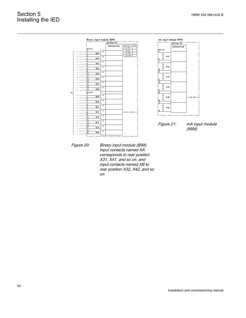
IEC08000480 BG V1 EN
Figure 20: Binary input module (BIM).Input contacts named XAcorresponds to rear positionX31, X41, and so on, andinput contacts named XB torear position X32, X42, and soon.
IEC08000484 BG V1 EN
Figure 21: mA input module(MIM)
Section 5 1MRK 504 088-UUS BInstalling the IED
54Installation and commissioning manual
IEC08000477 BG V1 EN
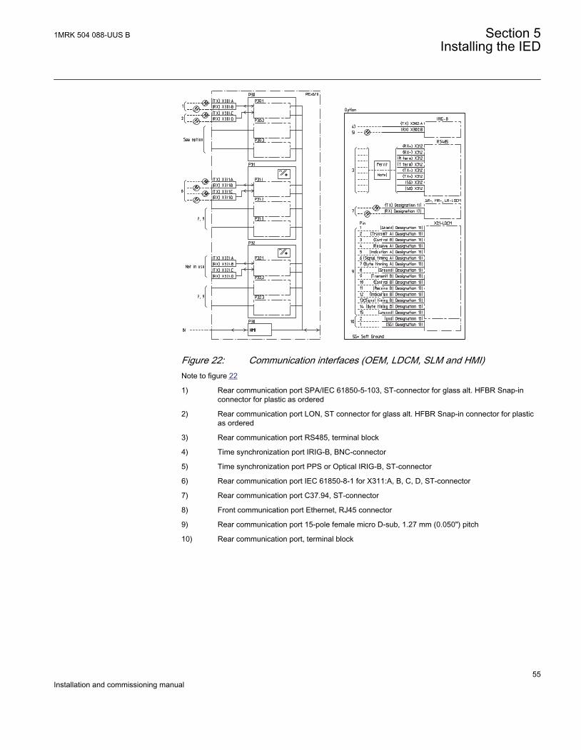
Figure 22: Communication interfaces (OEM, LDCM, SLM and HMI)Note to figure 22
1) Rear communication port SPA/IEC 61850-5-103, ST-connector for glass alt. HFBR Snap-inconnector for plastic as ordered
2) Rear communication port LON, ST connector for glass alt. HFBR Snap-in connector for plasticas ordered
3) Rear communication port RS485, terminal block
4) Time synchronization port IRIG-B, BNC-connector
5) Time synchronization port PPS or Optical IRIG-B, ST-connector
6) Rear communication port IEC 61850-8-1 for X311:A, B, C, D, ST-connector
7) Rear communication port C37.94, ST-connector
8) Front communication port Ethernet, RJ45 connector
9) Rear communication port 15-pole female micro D-sub, 1.27 mm (0.050") pitch
10) Rear communication port, terminal block
1MRK 504 088-UUS B Section 5Installing the IED
55Installation and commissioning manual
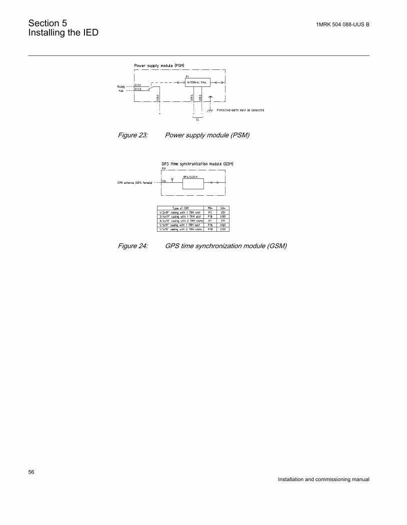
IEC08000476 BG V1 EN
Figure 23: Power supply module (PSM)
IEC08000478 BG V1 EN
Figure 24: GPS time synchronization module (GSM)
Section 5 1MRK 504 088-UUS BInstalling the IED
56Installation and commissioning manual
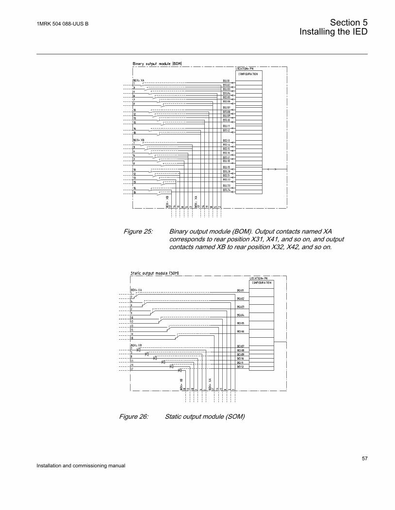
IEC08000481 BG V1 EN
Figure 25: Binary output module (BOM). Output contacts named XAcorresponds to rear position X31, X41, and so on, and outputcontacts named XB to rear position X32, X42, and so on.
IEC08000482 BG V1 EN
Figure 26: Static output module (SOM)
1MRK 504 088-UUS B Section 5Installing the IED
57Installation and commissioning manual
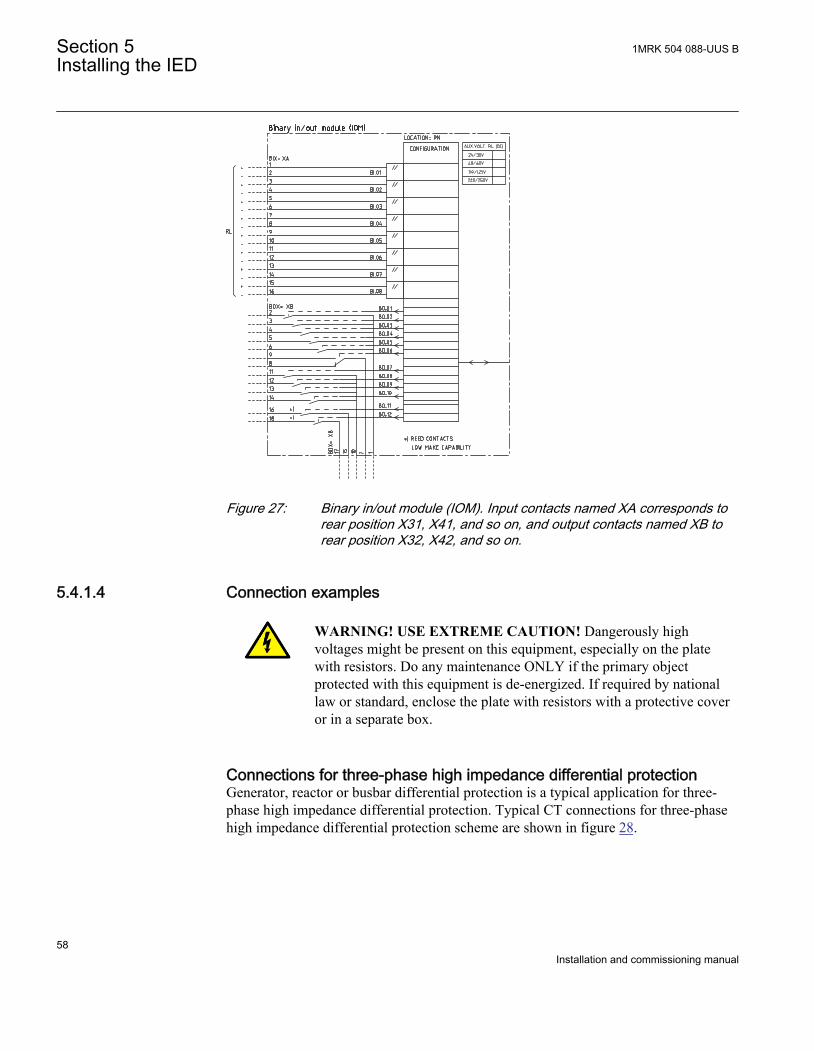
IEC08000483 BG V1 EN
Figure 27: Binary in/out module (IOM). Input contacts named XA corresponds torear position X31, X41, and so on, and output contacts named XB torear position X32, X42, and so on.
5.4.1.4 Connection examples
WARNING! USE EXTREME CAUTION! Dangerously highvoltages might be present on this equipment, especially on the platewith resistors. Do any maintenance ONLY if the primary objectprotected with this equipment is de-energized. If required by nationallaw or standard, enclose the plate with resistors with a protective coveror in a separate box.
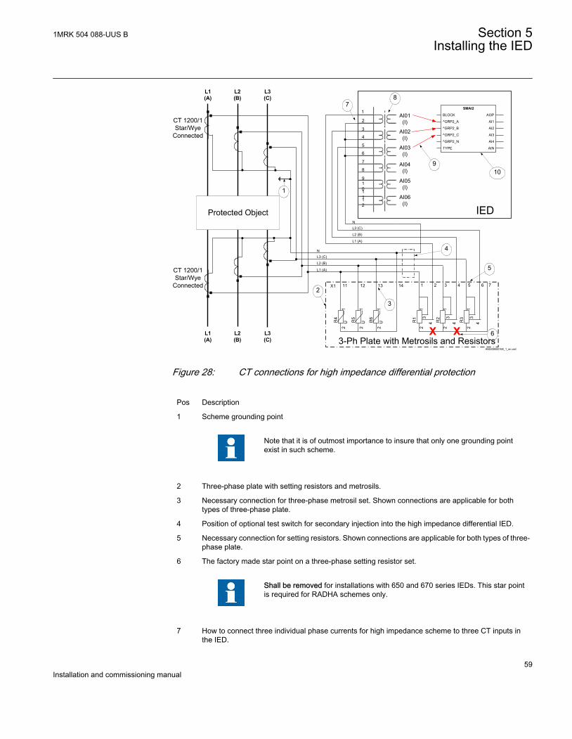
Connections for three-phase high impedance differential protectionGenerator, reactor or busbar differential protection is a typical application for three-phase high impedance differential protection. Typical CT connections for three-phasehigh impedance differential protection scheme are shown in figure 28.
Section 5 1MRK 504 088-UUS BInstalling the IED
58Installation and commissioning manual
L1(A)
L2(B)
L3(C)
Protected Object
CT 1200/1Star/Wye
Connected
L1(A)
L2(B)
L3(C)
CT 1200/1Star/Wye
Connected
7
8
9101112
1
2
3
4
5
6
AI01 (I)
AI02 (I)
AI03 (I)
AI04 (I)
AI05 (I)
AI06 (I)
78
6
9
X1
R4
R5
R6
12
12
12
11 12 13 14
U U U R1
13
4
2
13
R2
2
4
13
R3
2
4
1 2 3 4 5 6 7
L1 (A)
L2 (B)
L3 (C)N
3-Ph Plate with Metrosils and Resistors
2
3
5
4
10
X X
L1 (A)
L2 (B)
L3 (C)N
1
IED
ANSI09000169_1_en.vsd
AI3P
AI1
AI2
AI3
AI4
AIN
SMAI2
BLOCK
^GRP2_A
^GRP2_B
^GRP2_C
^GRP2_N
TYPE
ANSI09000169 V1 EN
Figure 28: CT connections for high impedance differential protection
Pos Description
1 Scheme grounding point
Note that it is of outmost importance to insure that only one grounding pointexist in such scheme.
2 Three-phase plate with setting resistors and metrosils.
3 Necessary connection for three-phase metrosil set. Shown connections are applicable for bothtypes of three-phase plate.
4 Position of optional test switch for secondary injection into the high impedance differential IED.
5 Necessary connection for setting resistors. Shown connections are applicable for both types of three-phase plate.
6 The factory made star point on a three-phase setting resistor set.
Shall be removed for installations with 650 and 670 series IEDs. This star pointis required for RADHA schemes only.
7 How to connect three individual phase currents for high impedance scheme to three CT inputs inthe IED.
1MRK 504 088-UUS B Section 5Installing the IED
59Installation and commissioning manual
8 Transformer input module, where the current inputs are located.
Note that the CT ratio for high impedance differential protection applicationmust be set as one.
• For main CTs with 1A secondary rating the following setting values shall be entered: CTprim= 1A and CTsec = 1A
• For main CTs with 5A secondary rating the following setting values shall be entered: CTprim= 5A and CTsec = 5A
• The parameter CTStarPoint shall be always left to the default value ToObject.
9 Three connections made in the Signal Matrix, which connect these three current inputs to the firstthree input channels of the preprocessing function block (10). For high impedance differentialprotection preprocessing function block in 3ms task shall be used.
10 Preprocessing block, to digitally filter the connected analogue inputs. Preprocessing block outputsAI1, AI2 and AI3 shall be connected to three instances of 1Ph high impedance differentialprotection HZPDIF (87) function blocks, for example instance 1, 2 and 3 of HZPDIF (87) in theconfiguration tool.
Connections for 1Ph High impedance differential protection HZPDIF (87)Restricted earth fault protection REFPDIF (87N) is a typical application for 1Ph Highimpedance differential protection HZPDIF (87). Typical CT connections for highimpedance based REFPDIF (87N) protection scheme are shown in figure 29.
Section 5 1MRK 504 088-UUS BInstalling the IED
60Installation and commissioning manual
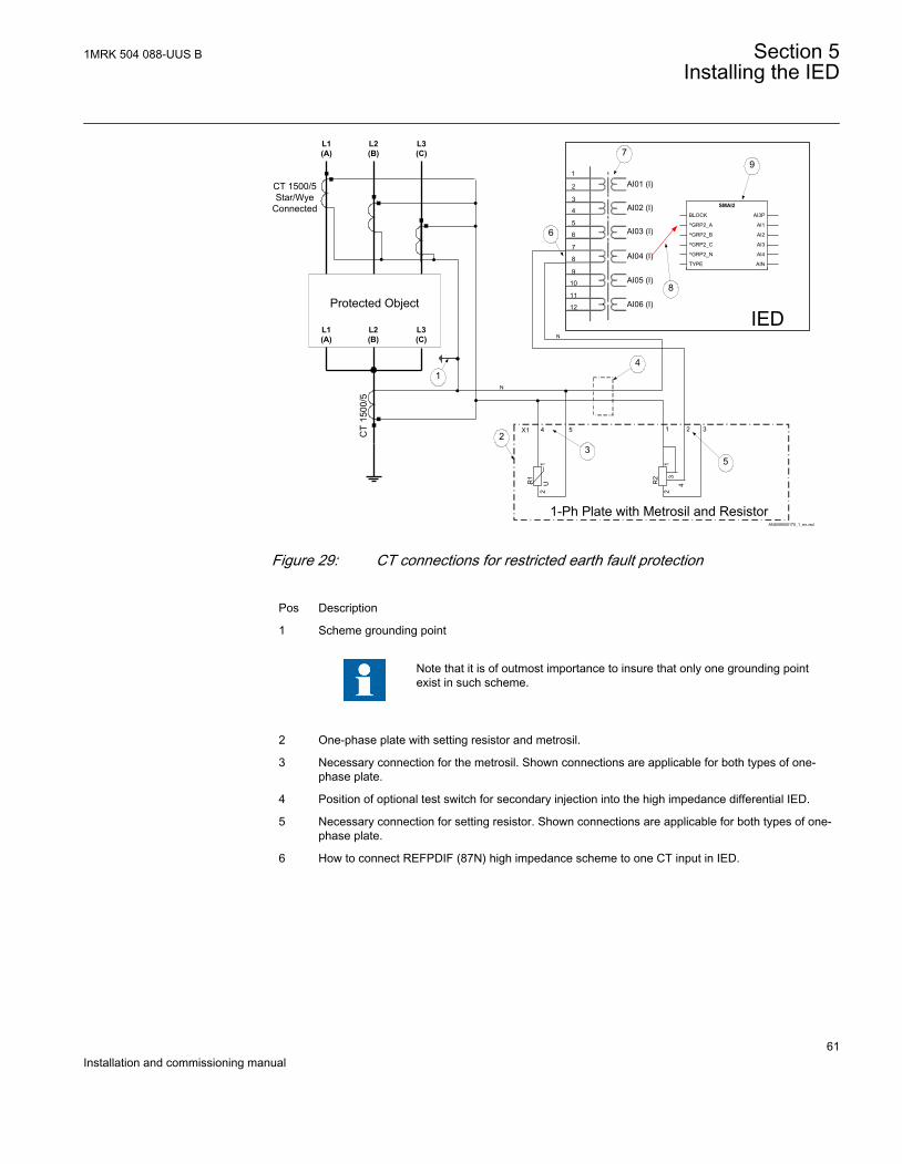
L1(A)
L2(B)
L3(C)
Protected Object
CT 1500/5Star/Wye
Connected
7
8
9
10
11
12
1
2
3
4
5
6
AI01 (I)
AI02 (I)
AI03 (I)
AI04 (I)
AI05 (I)
AI06 (I)
6
7
8
IED
X1
R1
12
4 5
U R2
13
4
2
1 2 3
N
1-Ph Plate with Metrosil and Resistor
23
5
4
9
N
L1(A)
L2(B)
L3(C)
CT
1500
/51
ANSI09000170_1_en.vsd
AI3P
AI1
AI2
AI3
AI4
AIN
SMAI2
BLOCK
^GRP2_A
^GRP2_B
^GRP2_C
^GRP2_N
TYPE
ANSI09000170 V1 EN
Figure 29: CT connections for restricted earth fault protection
Pos Description
1 Scheme grounding point
Note that it is of outmost importance to insure that only one grounding pointexist in such scheme.
2 One-phase plate with setting resistor and metrosil.
3 Necessary connection for the metrosil. Shown connections are applicable for both types of one-phase plate.
4 Position of optional test switch for secondary injection into the high impedance differential IED.
5 Necessary connection for setting resistor. Shown connections are applicable for both types of one-phase plate.
6 How to connect REFPDIF (87N) high impedance scheme to one CT input in IED.
1MRK 504 088-UUS B Section 5Installing the IED
61Installation and commissioning manual
7 Transformer input module where this current input is located.
Note that the CT ratio for high impedance differential protection applicationmust be set as one.
• For main CTs with 1A secondary rating the following setting values shall be entered: CTprim= 1A and CTsec = 1A
• For main CTs with 5A secondary rating the following setting values shall be entered: CTprim= 5A and CTsec = 5A
• The parameter CTStarPoint shall always be left to the default value ToObject
8 Connection made in the Signal Matrix, which connects this current input to first input channel of thepreprocessing function block (10). For high impedance differential protection preprocessingfunction block in 3ms task shall be used.
9 Preprocessing block, which has a task to digitally filter the connected analogue inputs.Preprocessing block output AI1 shall be connected to one instances of 1Ph high impedancedifferential protection function HZPDIF (87) (for example, instance 1 of HZPDIF (87) in theconfiguration tool).
5.4.2 Connecting to protective groundConnect the grounding screw (pos 1 in figure 30) on the rear of the IED to the closestpossible grounding point in the cubicle. Electrical codes and standards require thatprotective ground cables are green/yellow conductors with a cross section area of atleast 2.5 mm2 (AWG14). There are several protective grounding screws on an IED.The Power supply module (PSM), Transformer input modules (TRM) and theenclosure are all separately grounded, see figure 30 below.
The cubicle must be properly connected to the station grounding system. Use aconductor with a core cross section area of at least 4 mm2 (AWG 12).
Section 5 1MRK 504 088-UUS BInstalling the IED
62Installation and commissioning manual
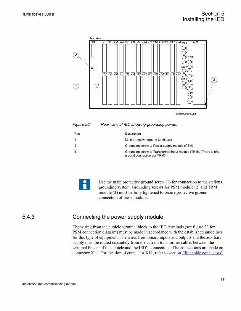
1
en05000509.vsd
3
2
IEC05000509 V1 EN
Figure 30: Rear view of IED showing grounding points.
Pos Description
1 Main protective ground to chassis
2 Grounding screw to Power supply module (PSM)
3 Grounding screw to Transformer input module (TRM). (There is oneground connection per TRM)
Use the main protective ground screw (1) for connection to the stationsgrounding system. Grounding screws for PSM module (2) and TRMmodule (3) must be fully tightened to secure protective groundconnection of these modules.
5.4.3 Connecting the power supply moduleThe wiring from the cubicle terminal block to the IED terminals (see figure 23 forPSM connection diagram) must be made in accordance with the established guidelinesfor this type of equipment. The wires from binary inputs and outputs and the auxiliarysupply must be routed separately from the current transformer cables between theterminal blocks of the cubicle and the IED's connections. The connections are made onconnector X11. For location of connector X11, refer to section "Rear side connectors".
1MRK 504 088-UUS B Section 5Installing the IED
63Installation and commissioning manual
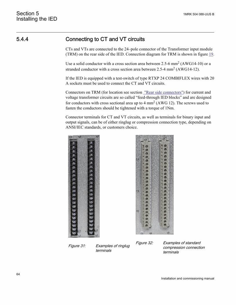
5.4.4 Connecting to CT and VT circuitsCTs and VTs are connected to the 24–pole connector of the Transformer input module(TRM) on the rear side of the IED. Connection diagram for TRM is shown in figure 19.
Use a solid conductor with a cross section area between 2.5-6 mm2 (AWG14-10) or astranded conductor with a cross section area between 2.5-4 mm2 (AWG14-12).
If the IED is equipped with a test-switch of type RTXP 24 COMBIFLEX wires with 20A sockets must be used to connect the CT and VT circuits.
Connectors on TRM (for location see section "Rear side connectors") for current andvoltage transformer circuits are so called “feed-through IED blocks” and are designedfor conductors with cross sectional area up to 4 mm2 (AWG 12). The screws used tofasten the conductors should be tightened with a torque of 1Nm.
Connector terminals for CT and VT circuits, as well as terminals for binary input andoutput signals, can be of either ringlug or compression connection type, depending onANSI/IEC standards, or customers choice.
IEC06000505 V1 EN
Figure 31: Examples of ringlugterminals
IEC06000506 V1 EN
Figure 32: Examples of standardcompression connectionterminals
Section 5 1MRK 504 088-UUS BInstalling the IED
64Installation and commissioning manual
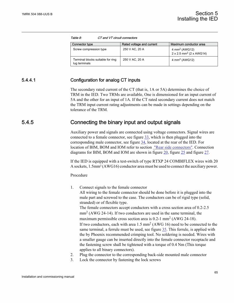
Table 8: CT and VT circuit connectors
Connector type Rated voltage and current Maximum conductor areaScrew compression type 250 V AC, 20 A 4 mm2 (AWG12)
2 x 2.5 mm2 (2 x AWG14)
Terminal blocks suitable for ringlug terminals
250 V AC, 20 A 4 mm2 (AWG12)
5.4.4.1 Configuration for analog CT inputs
The secondary rated current of the CT (that is, 1A or 5A) determines the choice ofTRM in the IED. Two TRMs are available, One is dimensioned for an input current of5A and the other for an input of 1A. If the CT rated secondary current does not matchthe TRM input current rating adjustments can be made in settings depending on thetolerance of the TRM.
5.4.5 Connecting the binary input and output signalsAuxiliary power and signals are connected using voltage connectors. Signal wires areconnected to a female connector, see figure 33, which is then plugged into thecorresponding male connector, see figure 34, located at the rear of the IED. Forlocation of BIM, BOM and IOM refer to section "Rear side connectors". Connectiondiagrams for BIM, BOM and IOM are shown in figure 20, figure 25 and figure 27.
If the IED is equipped with a test-switch of type RTXP 24 COMBIFLEX wires with 20A sockets, 1.5mm² (AWG16) conductor area must be used to connect the auxiliary power.
Procedure
1. Connect signals to the female connectorAll wiring to the female connector should be done before it is plugged into themale part and screwed to the case. The conductors can be of rigid type (solid,stranded) or of flexible type.The female connectors accept conductors with a cross section area of 0.2-2.5mm2 (AWG 24-14). If two conductors are used in the same terminal, themaximum permissible cross section area is 0.2-1 mm2 (AWG 24-18).If two conductors, each with area 1.5 mm2 (AWG 16) need to be connected to thesame terminal, a ferrule must be used, see figure 35. This ferrule, is applied withthe by Phoenix recommended crimping tool. No soldering is needed. Wires witha smaller gauge can be inserted directly into the female connector receptacle andthe fastening screw shall be tightened with a torque of 0.4 Nm (This torqueapplies to all binary connectors).
2. Plug the connector to the corresponding back-side mounted male connector3. Lock the connector by fastening the lock screws
1MRK 504 088-UUS B Section 5Installing the IED
65Installation and commissioning manual
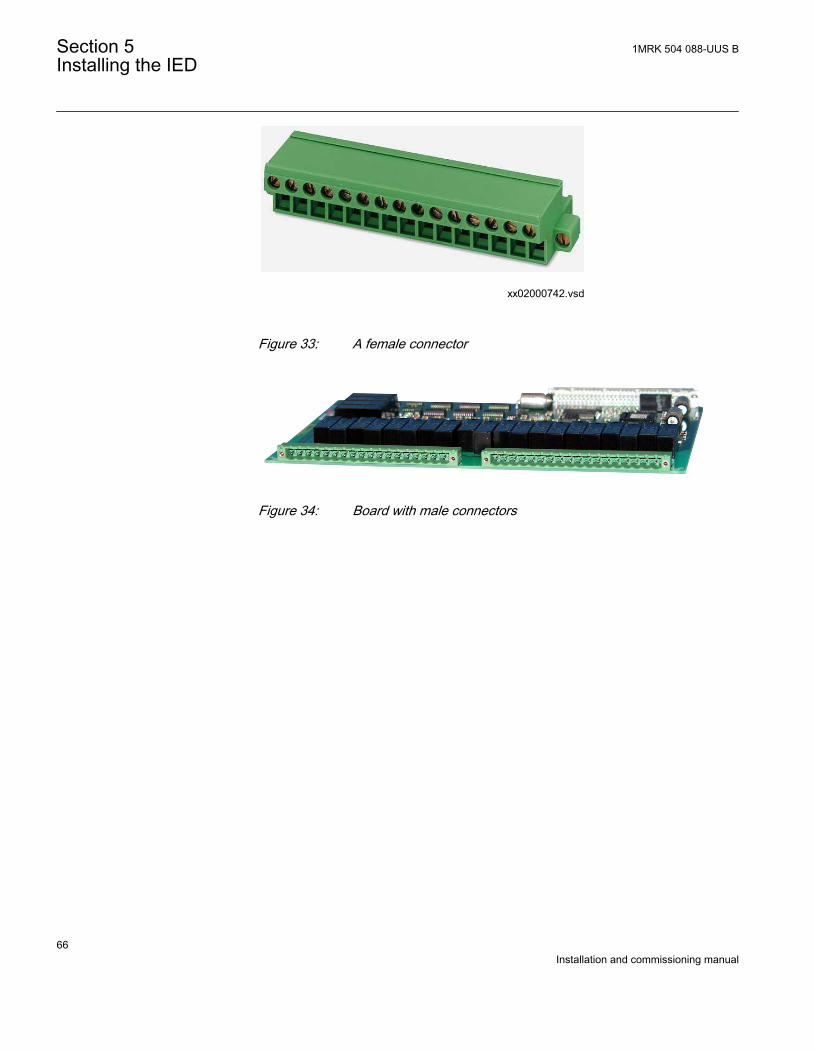
xx02000742.vsd
IEC02000742 V1 EN
Figure 33: A female connector
IEC04000167 V1 EN
Figure 34: Board with male connectors
Section 5 1MRK 504 088-UUS BInstalling the IED
66Installation and commissioning manual
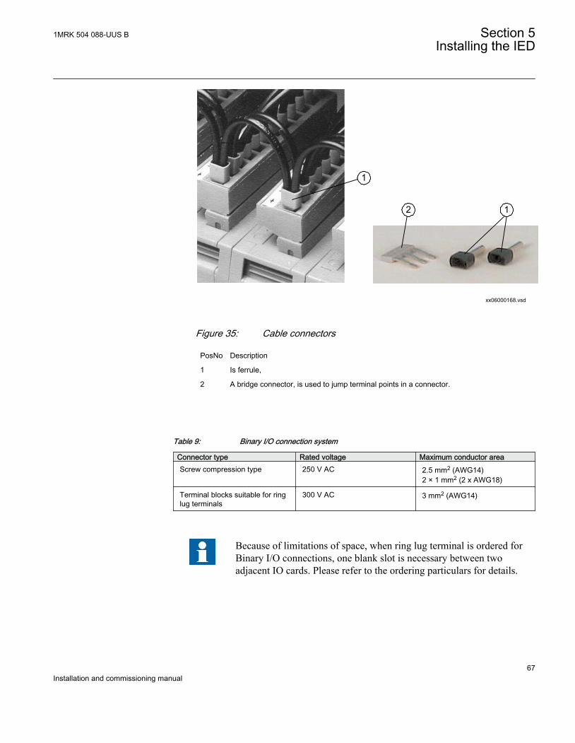
12
1
xx06000168.vsd
IEC06000168 V1 EN
Figure 35: Cable connectors
PosNo Description
1 Is ferrule,
2 A bridge connector, is used to jump terminal points in a connector.
Table 9: Binary I/O connection system
Connector type Rated voltage Maximum conductor areaScrew compression type 250 V AC 2.5 mm2 (AWG14)
2 × 1 mm2 (2 x AWG18)
Terminal blocks suitable for ringlug terminals
300 V AC 3 mm2 (AWG14)
Because of limitations of space, when ring lug terminal is ordered forBinary I/O connections, one blank slot is necessary between twoadjacent IO cards. Please refer to the ordering particulars for details.
1MRK 504 088-UUS B Section 5Installing the IED
67Installation and commissioning manual
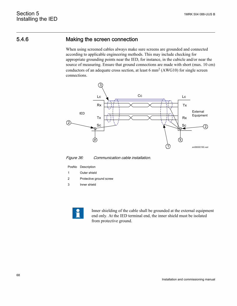
5.4.6 Making the screen connectionWhen using screened cables always make sure screens are grounded and connectedaccording to applicable engineering methods. This may include checking forappropriate grounding points near the IED, for instance, in the cubicle and/or near thesource of measuring. Ensure that ground connections are made with short (max. 10 cm)conductors of an adequate cross section, at least 6 mm2 (AWG10) for single screenconnections.
en06000190.vsd
Rx
Tx
Sc
Lc
Tx
Rx
Sc
LcCc
IED ExternalEquipment
1
3
22
IEC06000190 V1 EN
Figure 36: Communication cable installation.
PosNo Description
1 Outer shield
2 Protective ground screw
3 Inner shield
Inner shielding of the cable shall be grounded at the external equipmentend only. At the IED terminal end, the inner shield must be isolatedfrom protective ground.
Section 5 1MRK 504 088-UUS BInstalling the IED
68Installation and commissioning manual
5.5 Making the optical connections
5.5.1 Connecting station communication interfacesThe IED can be equipped with an optical ethernet module (OEM), see figure 22,needed for IEC 61850 communication and a serial communication module (SLM), seefigure 22 for LON, SPA or IEC 60870–5–103 communication. In such cases opticalports are provided on the rear side of the case for connection of the optical fibers. Forlocation of OEM and SLM, refer to section "Rear side connectors".
• Optical ports X311: A, B (Tx, Rx) and X311: C, D (Tx, Rx) on OEM are used forIEC 61850-8-1 communication. Connectors are of ST type. When OEM is used,the protection plate for the galvanic connection must not be removed.
• Optical port X301: A, B (Tx, Rx) on SLM module is used for SPA or IEC60870-5-103 communication. Connectors are of ST type (glass) or HFBR Snap in(plastic).
• Optical port X301: C, D (Tx, Rx) on SLM module is used for LONcommunication. Connectors are of ST type (glass) or HFBR Snap in (plastic).
The optical fibers have Transmission (Tx) and Reception (Rx) connectors, and theyshould be attached to the Tx and Rx connectors of OEM and SLM module (Tx cable toRx connector, Rx cable to Tx connector).
Connectors are generally color coded; connect blue or dark grey cable connectors toblue or dark grey (receive) back-side connectors. Connect black or grey cableconnectors to black or grey (transmit) back-side connectors.
The fiber optical cables are very sensitive to handling. Do not bend toosharply. The minimum curvature radius is 15 cm for the plastic fibercables and 25 cm for the glass fiber cables. If cable straps are used tofix the cables, apply with loose fit.Always hold the connector, never the cable, when connecting ordisconnecting optical fibers. Do not twist, pull or bend the fiber.Invisible damage may increase fiber attenuation thus makingcommunication impossible.
Please, strictly follow the instructions from the manufacturer for eachtype of optical cables/connectors.
1MRK 504 088-UUS B Section 5Installing the IED
69Installation and commissioning manual
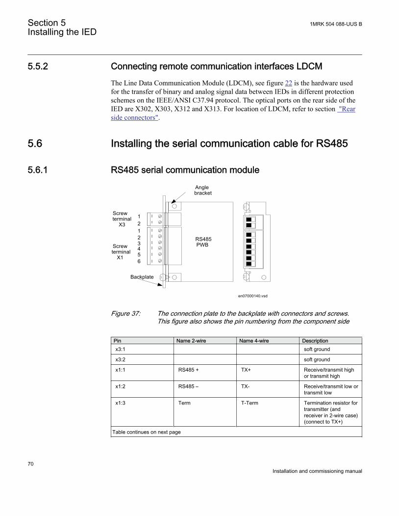
5.5.2 Connecting remote communication interfaces LDCMThe Line Data Communication Module (LDCM), see figure 22 is the hardware usedfor the transfer of binary and analog signal data between IEDs in different protectionschemes on the IEEE/ANSI C37.94 protocol. The optical ports on the rear side of theIED are X302, X303, X312 and X313. For location of LDCM, refer to section "Rearside connectors".
5.6 Installing the serial communication cable for RS485
5.6.1 RS485 serial communication module
RS485PWBScrew
terminalX1
Backplate
Screwterminal
X3
Anglebracket
12
456
3
12
en07000140.vsdIEC07000140 V1 EN
Figure 37: The connection plate to the backplate with connectors and screws.This figure also shows the pin numbering from the component side
Pin Name 2-wire Name 4-wire Descriptionx3:1 soft ground
x3:2 soft ground
x1:1 RS485 + TX+ Receive/transmit highor transmit high
x1:2 RS485 – TX- Receive/transmit low ortransmit low
x1:3 Term T-Term Termination resistor fortransmitter (andreceiver in 2-wire case)(connect to TX+)
Table continues on next page
Section 5 1MRK 504 088-UUS BInstalling the IED
70Installation and commissioning manual
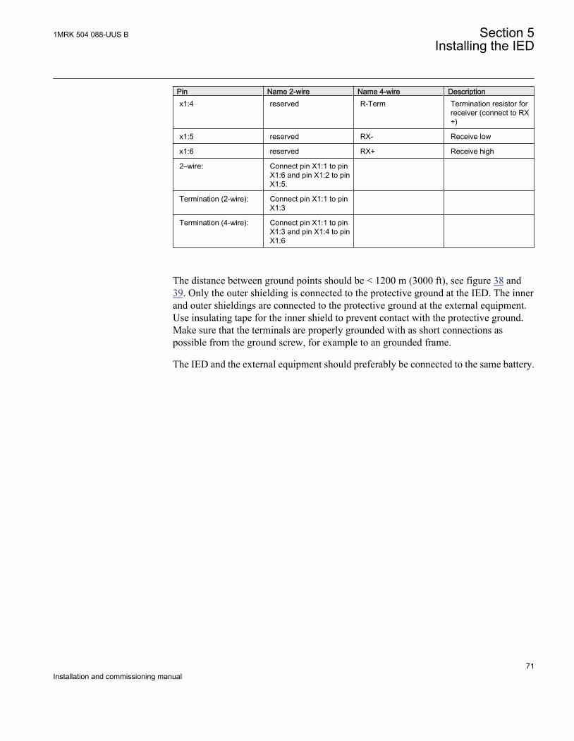
Pin Name 2-wire Name 4-wire Descriptionx1:4 reserved R-Term Termination resistor for
receiver (connect to RX+)
x1:5 reserved RX- Receive low
x1:6 reserved RX+ Receive high
2–wire: Connect pin X1:1 to pinX1:6 and pin X1:2 to pinX1:5.
Termination (2-wire): Connect pin X1:1 to pinX1:3
Termination (4-wire): Connect pin X1:1 to pinX1:3 and pin X1:4 to pinX1:6
The distance between ground points should be < 1200 m (3000 ft), see figure 38 and39. Only the outer shielding is connected to the protective ground at the IED. The innerand outer shieldings are connected to the protective ground at the external equipment.Use insulating tape for the inner shield to prevent contact with the protective ground.Make sure that the terminals are properly grounded with as short connections aspossible from the ground screw, for example to an grounded frame.
The IED and the external equipment should preferably be connected to the same battery.
1MRK 504 088-UUS B Section 5Installing the IED
71Installation and commissioning manual
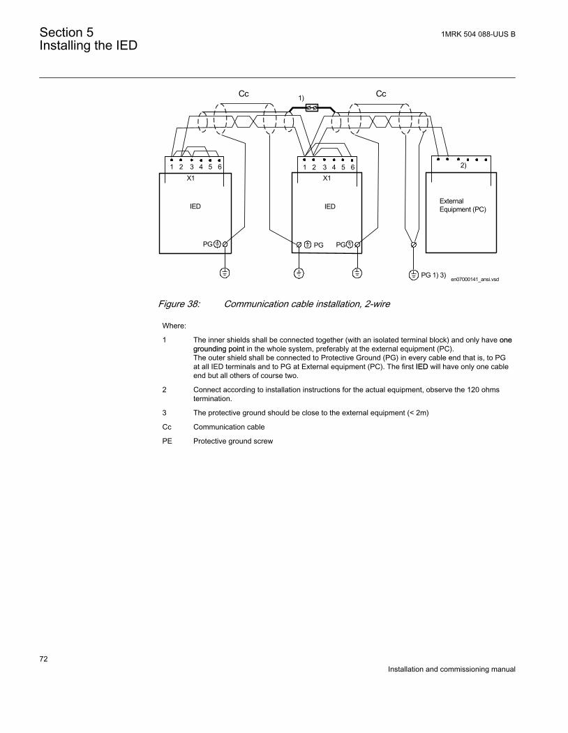
en07000141_ansi.vsd
Cc Cc1)
ExternalEquipment (PC)
PG 1) 3)
2)
PG
IED
X11 65432
IED
1 65432X1
PGPG
ANSI07000141 V1 EN
Figure 38: Communication cable installation, 2-wire
Where:
1 The inner shields shall be connected together (with an isolated terminal block) and only have onegrounding point in the whole system, preferably at the external equipment (PC).The outer shield shall be connected to Protective Ground (PG) in every cable end that is, to PGat all IED terminals and to PG at External equipment (PC). The first IED will have only one cableend but all others of course two.
2 Connect according to installation instructions for the actual equipment, observe the 120 ohmstermination.
3 The protective ground should be close to the external equipment (< 2m)
Cc Communication cable
PE Protective ground screw
Section 5 1MRK 504 088-UUS BInstalling the IED
72Installation and commissioning manual
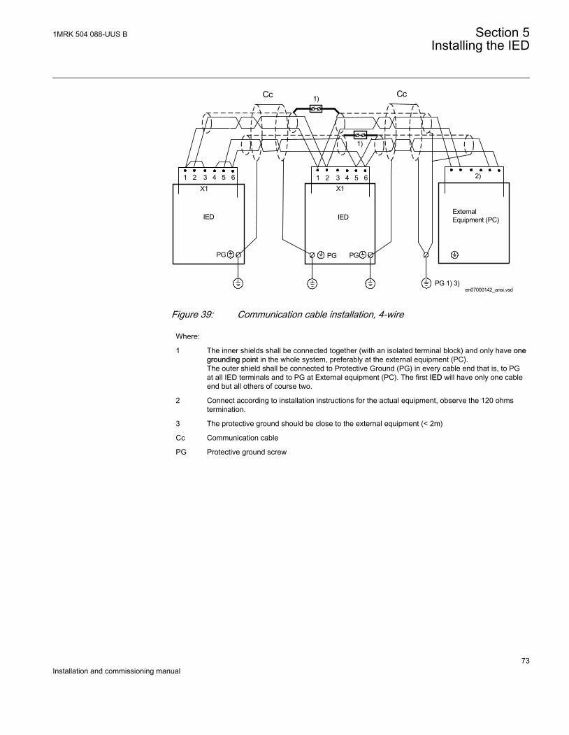
en07000142_ansi.vsd
ExternalEquipment (PC)
PG 1) 3)
2)
IED
1 65432X1
PGPG
Cc
PG
IED
X11 65432
1)
1)
Cc
ANSI07000142 V1 EN
Figure 39: Communication cable installation, 4-wire
Where:
1 The inner shields shall be connected together (with an isolated terminal block) and only have onegrounding point in the whole system, preferably at the external equipment (PC).The outer shield shall be connected to Protective Ground (PG) in every cable end that is, to PGat all IED terminals and to PG at External equipment (PC). The first IED will have only one cableend but all others of course two.
2 Connect according to installation instructions for the actual equipment, observe the 120 ohmstermination.
3 The protective ground should be close to the external equipment (< 2m)
Cc Communication cable
PG Protective ground screw
1MRK 504 088-UUS B Section 5Installing the IED
73Installation and commissioning manual
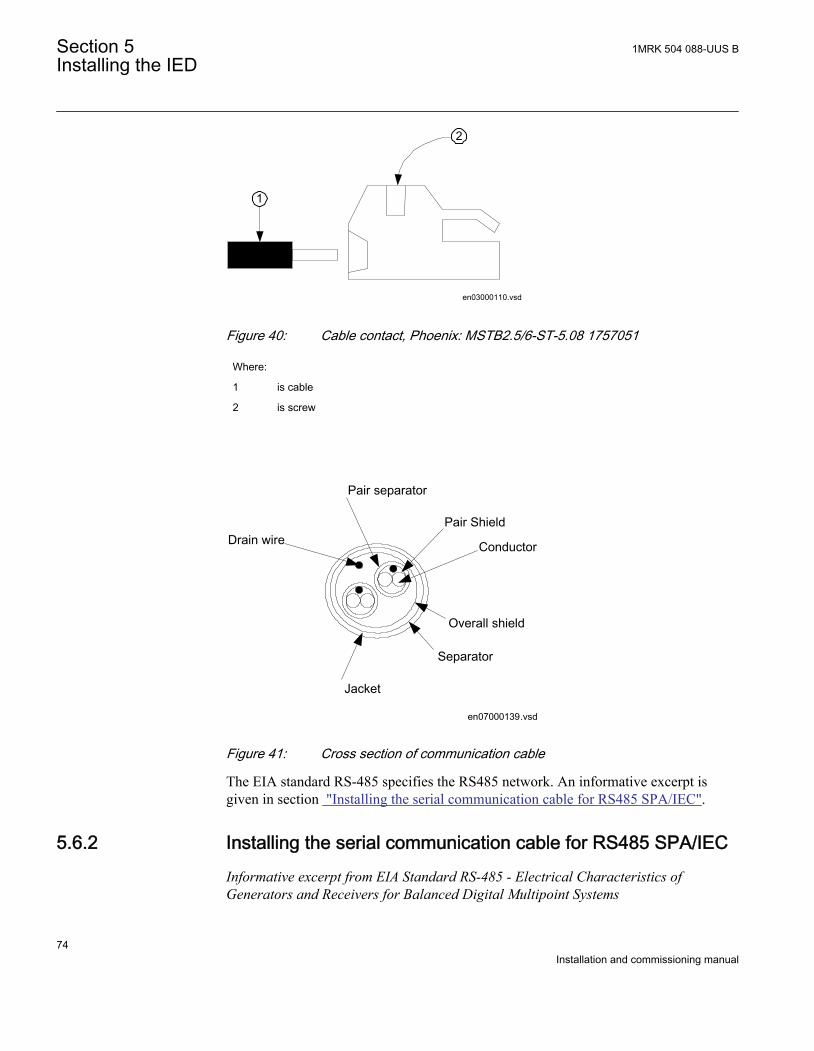
en03000110.vsd
1
2
IEC03000110 V1 EN
Figure 40: Cable contact, Phoenix: MSTB2.5/6-ST-5.08 1757051
Where:
1 is cable
2 is screw
Conductor
Pair Shield
Pair separator
Jacket
Separator
Overall shield
Drain wire
en07000139.vsdIEC07000139 V1 EN
Figure 41: Cross section of communication cable
The EIA standard RS-485 specifies the RS485 network. An informative excerpt isgiven in section "Installing the serial communication cable for RS485 SPA/IEC".
5.6.2 Installing the serial communication cable for RS485 SPA/IECInformative excerpt from EIA Standard RS-485 - Electrical Characteristics ofGenerators and Receivers for Balanced Digital Multipoint Systems
Section 5 1MRK 504 088-UUS BInstalling the IED
74Installation and commissioning manual
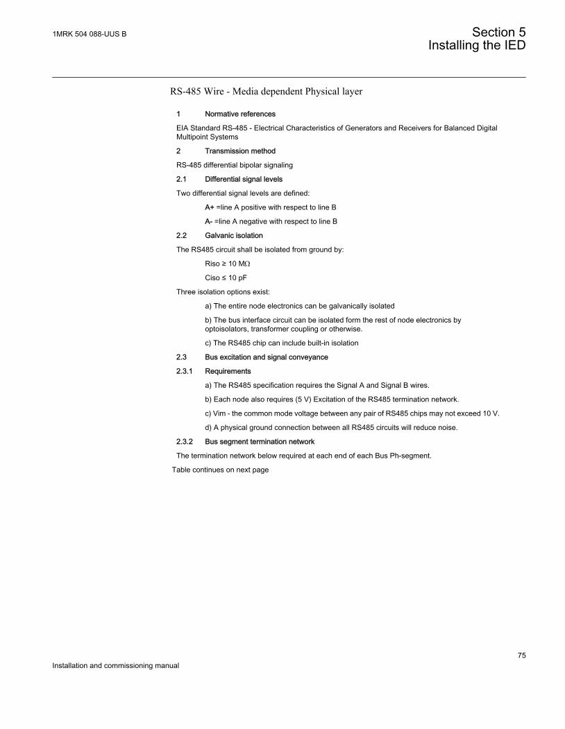
RS-485 Wire - Media dependent Physical layer
1 Normative references
EIA Standard RS-485 - Electrical Characteristics of Generators and Receivers for Balanced DigitalMultipoint Systems
2 Transmission method
RS-485 differential bipolar signaling
2.1 Differential signal levels
Two differential signal levels are defined:
A+ =line A positive with respect to line B
A- =line A negative with respect to line B
2.2 Galvanic isolation
The RS485 circuit shall be isolated from ground by:
Riso ≥ 10 MW
Ciso ≤ 10 pF
Three isolation options exist:
a) The entire node electronics can be galvanically isolated
b) The bus interface circuit can be isolated form the rest of node electronics byoptoisolators, transformer coupling or otherwise.
c) The RS485 chip can include built-in isolation
2.3 Bus excitation and signal conveyance
2.3.1 Requirements
a) The RS485 specification requires the Signal A and Signal B wires.
b) Each node also requires (5 V) Excitation of the RS485 termination network.
c) Vim - the common mode voltage between any pair of RS485 chips may not exceed 10 V.
d) A physical ground connection between all RS485 circuits will reduce noise.
2.3.2 Bus segment termination network
The termination network below required at each end of each Bus Ph-segment.
Table continues on next page
1MRK 504 088-UUS B Section 5Installing the IED
75Installation and commissioning manual

en03000112.vsd
ExV+
Signal B
Signal A
DGND
Ru = 390 ohm1/4 W, 2%
Rt = 220 ohm1/4 W, 2%
Rd = 390 ohm1/4 W, 2%
ExV is supplied by the Node at end of the Bus Segment
IEC03000112 V1 EN
Figure 42: RS-485 bus segment terminationExV is supplied by the Node at end of the Bus Segment
The specifications of the components are:
a) Ru + 5 V to Signal B = 390 W, 0.25 W ±2.5%
b) Rt Signal B to Signal A = 220 W, 0.25 W ±2.5%
c) Rd Signal A to GND = 390 W, 0.25 W ±2.5%
2.3.3 Bus power distribution
The end node in each Ph-segment applies 5 V bus excitation power to the Termination network viathe Excitation pair (ExV+ and GND) used in the Type 3 Physical layer specification.
5.6.3 Data on RS485 serial communication module cable
Type: Twisted-pair S-STP (Screened – Screened Twisted Pair)
Shield: Individual foil for each pair with overall copper braid
Length: Maximum 1200 m (3000 ft) from one system ground to the next system ground(includes length from platform point to system ground on both sides)
Temp: According to application
Impedance: 120 W
Capacitance: Less than or equal to 42 pF/m
Example: Belden 9841,Alpha wire 6412, 6413
Section 5 1MRK 504 088-UUS BInstalling the IED
76Installation and commissioning manual
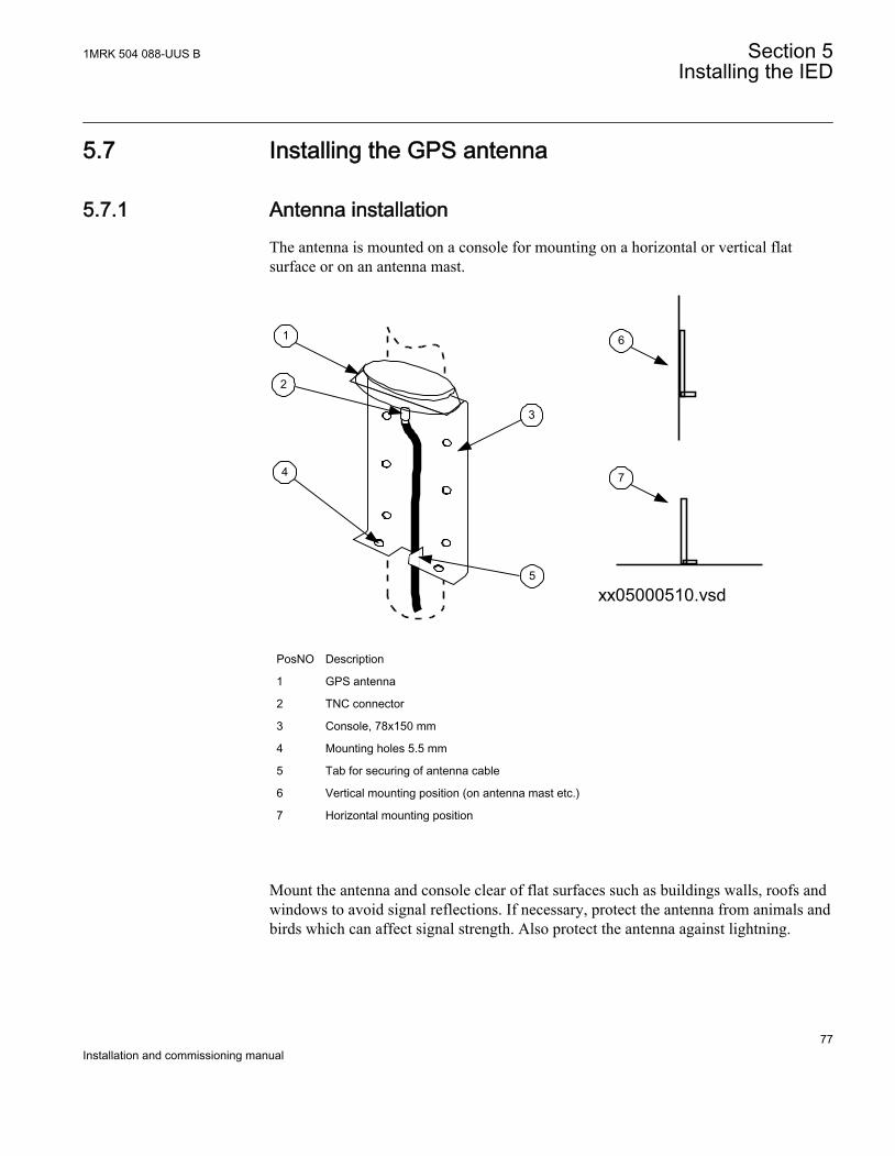
5.7 Installing the GPS antenna
5.7.1 Antenna installationThe antenna is mounted on a console for mounting on a horizontal or vertical flatsurface or on an antenna mast.
1
2
4
3
5
6
7
xx05000510.vsd
IEC05000510 V1 EN
PosNO Description
1 GPS antenna
2 TNC connector
3 Console, 78x150 mm
4 Mounting holes 5.5 mm
5 Tab for securing of antenna cable
6 Vertical mounting position (on antenna mast etc.)
7 Horizontal mounting position
Mount the antenna and console clear of flat surfaces such as buildings walls, roofs andwindows to avoid signal reflections. If necessary, protect the antenna from animals andbirds which can affect signal strength. Also protect the antenna against lightning.
1MRK 504 088-UUS B Section 5Installing the IED
77Installation and commissioning manual
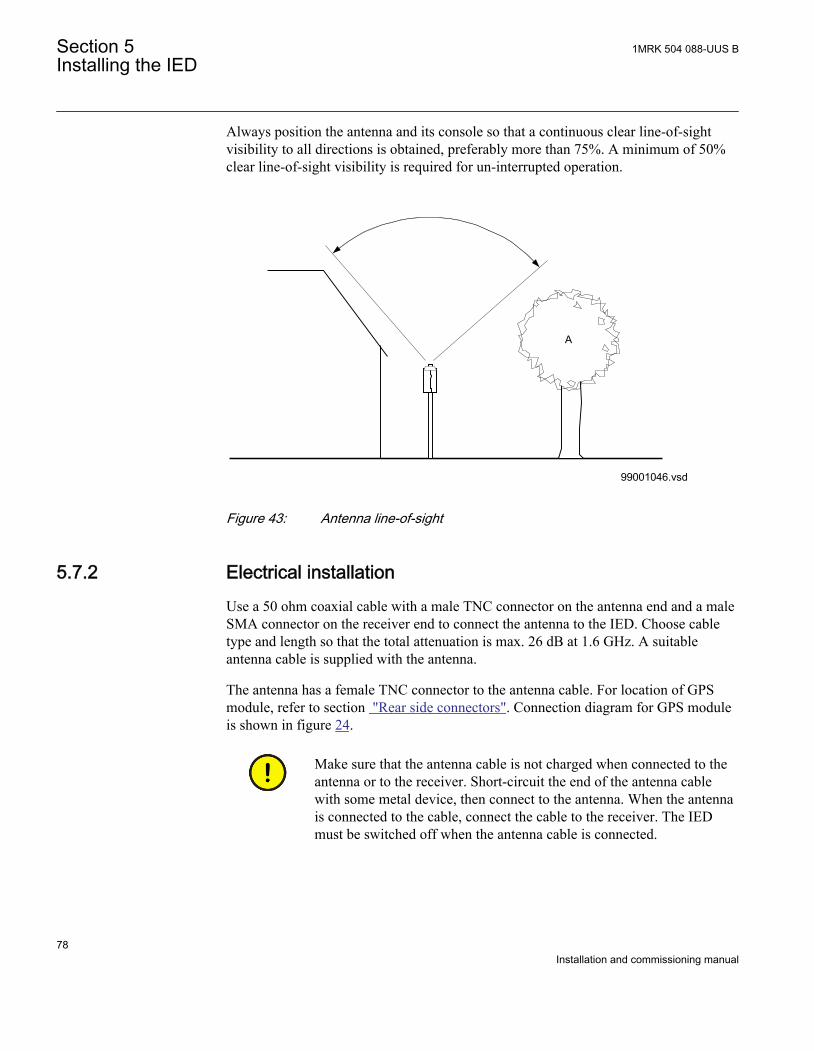
Always position the antenna and its console so that a continuous clear line-of-sightvisibility to all directions is obtained, preferably more than 75%. A minimum of 50%clear line-of-sight visibility is required for un-interrupted operation.
A
99001046.vsdIEC99001046 V1 EN
Figure 43: Antenna line-of-sight
5.7.2 Electrical installationUse a 50 ohm coaxial cable with a male TNC connector on the antenna end and a maleSMA connector on the receiver end to connect the antenna to the IED. Choose cabletype and length so that the total attenuation is max. 26 dB at 1.6 GHz. A suitableantenna cable is supplied with the antenna.
The antenna has a female TNC connector to the antenna cable. For location of GPSmodule, refer to section "Rear side connectors". Connection diagram for GPS moduleis shown in figure 24.
Make sure that the antenna cable is not charged when connected to theantenna or to the receiver. Short-circuit the end of the antenna cablewith some metal device, then connect to the antenna. When the antennais connected to the cable, connect the cable to the receiver. The IEDmust be switched off when the antenna cable is connected.
Section 5 1MRK 504 088-UUS BInstalling the IED
78Installation and commissioning manual

5.7.3 Lightning protectionThe antenna should be mounted with adequate lightning protection, that is the antennamast must not rise above a neighboring lightning conductor.
1MRK 504 088-UUS B Section 5Installing the IED
79Installation and commissioning manual

80

Section 6 Checking the external optical and electricalconnections
About this chapterThis chapter describes what to check to ensure correct connection to the externalcircuitry, such as the auxiliary power supply, CT’s and VT’s. These checks must bemade with the protection IED de-energized.
6.1 Overview
The user must check the installation which includes verifying that the IED is connectedto the other parts of the protection system. This is done with the IED and all connectedcircuits de-energized.
6.2 Checking VT circuits
Check that the wiring is in strict accordance with the supplied connection diagram.
Correct all errors before continuing to test circuitry.
Test the circuitry.
• Polarity check• VT circuit voltage measurement (primary injection test)• Grounding check• Phase relationship• Insulation resistance check
The polarity check verifies the integrity of circuits and the phase relationships. Thecheck should be performed as close to the IED as possible.
The primary injection test verifies the VT ratio and the wiring all the way through fromthe primary system to the IED. Injection must be performed for each phase-to-neutral
1MRK 504 088-UUS B Section 6Checking the external optical and electrical connections
81Installation and commissioning manual
circuit and each phase-to-phase pair. In each case voltages in all phases and neutral aremeasured.
6.3 Checking CT circuits
The CTs must be connected in accordance with the circuit diagram provided with theIED, both with regards to phases and polarity. The following tests shall be performedon every primary CT connected to the IED:
• Primary injection test to verify the current ratio of the CT, the correct wiring up tothe protection IED and correct phase sequence connection (that is A, B, C.)
• Polarity check to prove that the predicted direction of secondary current flow iscorrect for a given direction of primary current flow. This is an essential test forthe proper operation of the differential function.
• CT secondary loop resistance measurement to confirm that the current transformersecondary loop dc resistance is within specification and that there are no highresistance joints in the CT winding or wiring.
• CT excitation test in order to confirm that the current transformer is of the correctaccuracy rating and that there are no shorted turns in the current transformerwindings. Manufacturer's design curves should be available for the currenttransformer to compare the actual results.
• Grounding check of the individual CT secondary circuits to verify that each three-phase set of main CTs is properly connected to the station ground and only at oneelectrical point.
• Insulation resistance check.• Phase identification of CT shall be made.
Both primary and secondary sides must be disconnected from the lineand IED when plotting the excitation characteristics.
If the CT secondary circuit ground connection is removed without thecurrent transformer primary being de-energized, dangerous voltagesmay result in the secondary CT circuits.
Section 6 1MRK 504 088-UUS BChecking the external optical and electrical connections
82Installation and commissioning manual
6.4 Checking the power supply
Check that the auxiliary supply voltage remains within the permissible input voltagerange under all operating conditions. Check that the polarity is correct before poweringthe IED.
6.5 Checking the binary I/O circuits
6.5.1 Binary input circuitsPreferably, disconnect the binary input connector from the binary input cards. Checkall connected signals so that both input level and polarity are in accordance with theIEDs specifications.
6.5.2 Binary output circuitsPreferably, disconnect the binary output connector from the binary output cards. Checkall connected signals so that both load and polarity are in accordance with IEDspecifications.
6.6 Checking optical connections
Check that the Tx and Rx optical connections are correct.
An IED equipped with optical connections requires a minimum depthof 180 mm for plastic fiber cables and 275 mm for glass fiber cables.The allowed minimum bending radius has to be checked from theoptical cable manufacturer.
1MRK 504 088-UUS B Section 6Checking the external optical and electrical connections
83Installation and commissioning manual

84
Section 7 Energizing the IED
About this chapterThis chapter describes the start-up sequence and what to check once the IED has beenenergized.
7.1 Check the IED operation
Check all connections to external circuitry to ensure that the installation was madecorrectly, before energizing the IED and carrying out the commissioning procedures.
The user could also check the software version, the IED's serial number and theinstalled modules and their ordering number to ensure that the IED is according todelivery and ordering specifications.
Energize the power supply of the IED to start it up. This could be done in number ofways, from energizing a whole cubicle to energizing a single IED. The user should re-configure the IED to activate the hardware modules in order to enable the selfsupervision function to detect possible hardware errors. The IED time must be set. Theself-supervision function in the Main menu/Diagnostics/Monitoring menu in localHMI should also be checked to verify that the IED operates properly.
7.2 Energizing the IED
When the IED is energized, the green LED instantly starts flashing. Afterapproximately 55 seconds the window lights up and the window displays ‘IEDStartup’. The main menu is displayed and the upper row should indicate ‘Ready’ afterabout 90 seconds. A steady green light indicates a successful startup.
1MRK 504 088-UUS B Section 7Energizing the IED
85Installation and commissioning manual
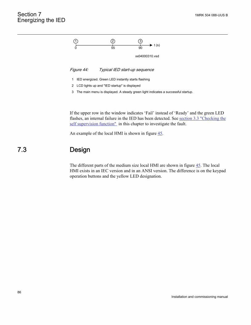
xx04000310.vsd
t (s)0 55 90
1 32
IEC04000310 V1 EN
Figure 44: Typical IED start-up sequence
1 IED energized. Green LED instantly starts flashing
2 LCD lights up and "IED startup" is displayed
3 The main menu is displayed. A steady green light indicates a successful startup.
If the upper row in the window indicates ‘Fail’ instead of ‘Ready’ and the green LEDflashes, an internal failure in the IED has been detected. See section 3.3 "Checking theself supervision function" in this chapter to investigate the fault.
An example of the local HMI is shown in figure 45.
7.3 Design
The different parts of the medium size local HMI are shown in figure 45. The localHMI exists in an IEC version and in an ANSI version. The difference is on the keypadoperation buttons and the yellow LED designation.
Section 7 1MRK 504 088-UUS BEnergizing the IED
86Installation and commissioning manual
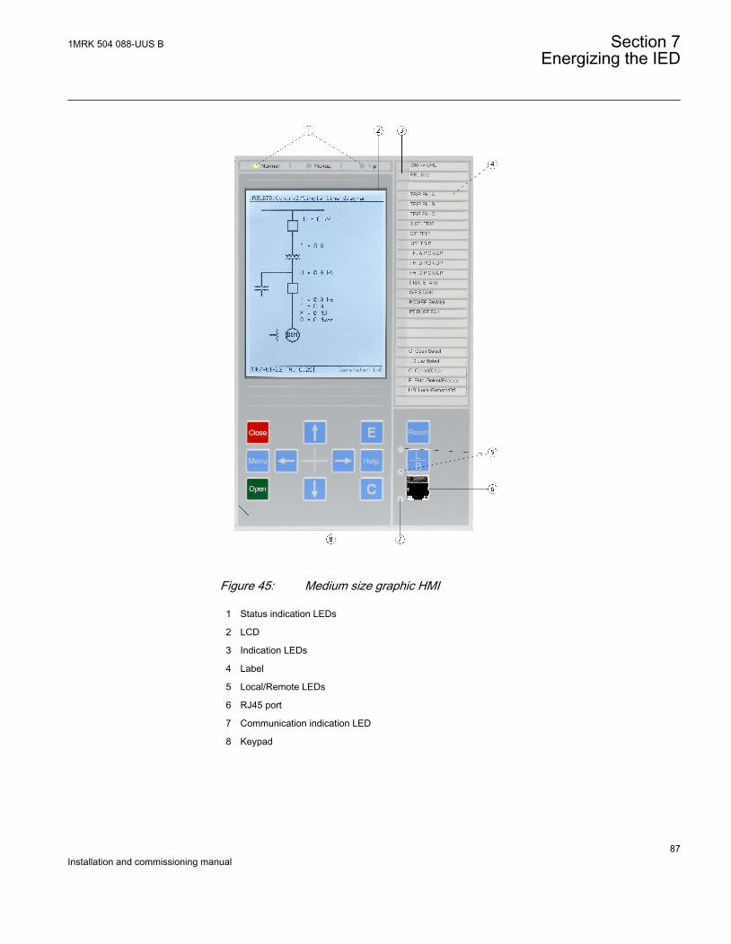
IEC07000077-CALLOUT V1 EN
Figure 45: Medium size graphic HMI
1 Status indication LEDs
2 LCD
3 Indication LEDs
4 Label
5 Local/Remote LEDs
6 RJ45 port
7 Communication indication LED
8 Keypad
1MRK 504 088-UUS B Section 7Energizing the IED
87Installation and commissioning manual
7.4 Checking the self supervision signals
7.4.1 Reconfiguring the IEDI/O modules configured as logical I/O modules (BIM, BOM or IOM) are supervised.
I/O modules that are not configured are not supervised.
Each logical I/O module has an error flag that indicates signal or module failure. Theerror flag is also set when the physical I/O module of the correct type is not detected inthe connected slot.
7.4.2 Setting the IED timeThis procedure describes how to set the IED time from the local HMI.
1. Display the set time dialog.Navigate to Main menu/Settings/Time/System timePress the E button to enter the dialog.
2. Set the date and time.Use the Left and Right arrow buttons to move between the time and date values(year, month, day, hours, minutes and seconds). Use the Up and Down arrowbuttons to change the value.
3. Confirm the setting.Press the E button to set the calendar and clock to the new values.
7.4.3 Checking the self supervision function
7.4.3.1 Determine the cause of an internal failure
This procedure describes how to navigate the menus in order to find the cause of aninternal failure when indicated by the flashing green LED on the HMI module.
Procedure
1. Display the general diagnostics menu.Navigate the menus to:Diagnostics/IED status/General
2. Scroll the supervision values to identify the reason for the failure.Use the arrow buttons to scroll between values.
Section 7 1MRK 504 088-UUS BEnergizing the IED
88Installation and commissioning manual
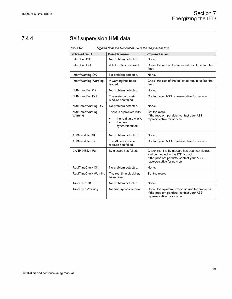
7.4.4 Self supervision HMI dataTable 10: Signals from the General menu in the diagnostics tree.
Indicated result Possible reason Proposed actionInternFail OK No problem detected. None.
InternFail Fail A failure has occurred. Check the rest of the indicated results to find thefault.
InternWarning OK No problem detected. None.
InternWarning Warning A warning has beenissued.
Check the rest of the indicated results to find thefault.
NUM-modFail OK No problem detected. None.
NUM-modFail Fail The main processingmodule has failed.
Contact your ABB representative for service.
NUM-modWarning OK No problem detected. None.
NUM-modWarningWarning
There is a problem with:
• the real time clock.• the time
synchronization.
Set the clock.If the problem persists, contact your ABBrepresentative for service.
ADC-module OK No problem detected. None.
ADC-module Fail The AD conversionmodule has failed.
Contact your ABB representative for service.
CANP 9 BIM1 Fail IO module has failed. Check that the IO module has been configuredand connected to the IOP1- block.If the problem persists, contact your ABBrepresentative for service.
RealTimeClock OK No problem detected. None.
RealTimeClock Warning The real time clock hasbeen reset.
Set the clock.
TimeSync OK No problem detected. None.
TimeSync Warning No time synchronization. Check the synchronization source for problems.If the problem persists, contact your ABBrepresentative for service.
1MRK 504 088-UUS B Section 7Energizing the IED
89Installation and commissioning manual

90

Section 8 Set up the PCM600 communication link perIED
About this chapterThis chapter describes the communication between the IED and PCM600.
8.1 Setting up communication between PCM600 and theIED
The communication between the IED and PCM600 is independent of the usedcommunication protocol within the substation or to the NCC.
The communication media is always Ethernet and the used protocol is TCP/IP.
Each IED has an Ethernet interface connector on the front and on the rear side. TheEthernet connector can be used for communication with PCM600.
When an Ethernet based station protocol is used, PCM600 communication can use thesame Ethernet port and IP address.
For the connection of PCM600 to the IED two basic variants have to be considered.
• Direct point to point link between PCM600 and the IED front port. The front portcan be seen as a service port.
• Indirect link via a station LAN or from remote via a network.
The physical connection and the IP address must be configured in both cases to enablecommunication.
The communication procedures are in both cases the same.
1. If needed, set the IP address for the IEDs.2. Set up the PC or workstation for a direct link (point to point), or3. Connect the PC or workstation to the LAN/WAN network.4. Configure the IED IP addresses in the PCM600 project for each IED to match the
IP addresses of the physical IEDs.
1MRK 504 088-UUS B Section 8Set up the PCM600 communication link per IED
91Installation and commissioning manual
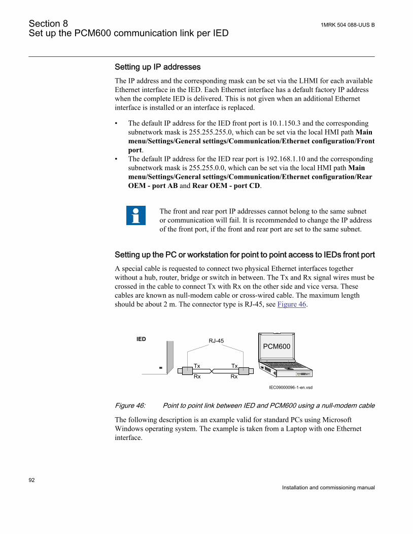
Setting up IP addressesThe IP address and the corresponding mask can be set via the LHMI for each availableEthernet interface in the IED. Each Ethernet interface has a default factory IP addresswhen the complete IED is delivered. This is not given when an additional Ethernetinterface is installed or an interface is replaced.
• The default IP address for the IED front port is 10.1.150.3 and the correspondingsubnetwork mask is 255.255.255.0, which can be set via the local HMI path Mainmenu/Settings/General settings/Communication/Ethernet configuration/Frontport.
• The default IP address for the IED rear port is 192.168.1.10 and the correspondingsubnetwork mask is 255.255.0.0, which can be set via the local HMI path Mainmenu/Settings/General settings/Communication/Ethernet configuration/RearOEM - port AB and Rear OEM - port CD.
The front and rear port IP addresses cannot belong to the same subnetor communication will fail. It is recommended to change the IP addressof the front port, if the front and rear port are set to the same subnet.
Setting up the PC or workstation for point to point access to IEDs front portA special cable is requested to connect two physical Ethernet interfaces togetherwithout a hub, router, bridge or switch in between. The Tx and Rx signal wires must becrossed in the cable to connect Tx with Rx on the other side and vice versa. Thesecables are known as null-modem cable or cross-wired cable. The maximum lengthshould be about 2 m. The connector type is RJ-45, see Figure 46.
IEC09000096-1-en.vsd
PCM600
Tx Tx
Rx Rx
RJ-45IED
IEC09000096 V1 EN
Figure 46: Point to point link between IED and PCM600 using a null-modem cable
The following description is an example valid for standard PCs using MicrosoftWindows operating system. The example is taken from a Laptop with one Ethernetinterface.
Section 8 1MRK 504 088-UUS BSet up the PCM600 communication link per IED
92Installation and commissioning manual
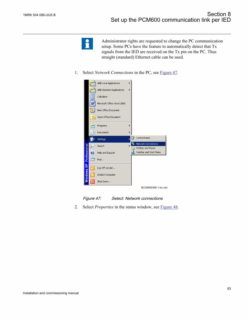
Administrator rights are requested to change the PC communicationsetup. Some PCs have the feature to automatically detect that Txsignals from the IED are received on the Tx pin on the PC. Thusstraight (standard) Ethernet cable can be used.
1. Select Network Connections in the PC, see Figure 47.
IEC09000355-1-en.vsdIEC09000355 V1 EN
Figure 47: Select: Network connections
2. Select Properties in the status window, see Figure 48.
1MRK 504 088-UUS B Section 8Set up the PCM600 communication link per IED
93Installation and commissioning manual
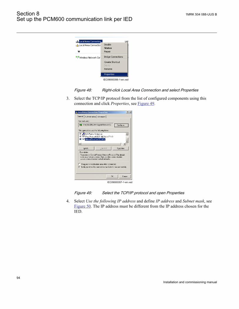
IEC09000356-1-en.vsdIEC09000356 V1 EN
Figure 48: Right-click Local Area Connection and select Properties
3. Select the TCP/IP protocol from the list of configured components using thisconnection and click Properties, see Figure 49.
IEC09000357-1-en.vsdIEC09000357 V1 EN
Figure 49: Select the TCP/IP protocol and open Properties
4. Select Use the following IP address and define IP address and Subnet mask, seeFigure 50. The IP address must be different from the IP address chosen for theIED.
Section 8 1MRK 504 088-UUS BSet up the PCM600 communication link per IED
94Installation and commissioning manual
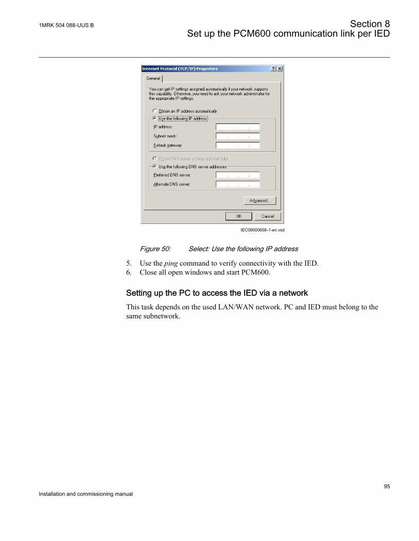
IEC09000658-1-en.vsdIEC09000658 V1 EN
Figure 50: Select: Use the following IP address
5. Use the ping command to verify connectivity with the IED.6. Close all open windows and start PCM600.
Setting up the PC to access the IED via a networkThis task depends on the used LAN/WAN network. PC and IED must belong to thesame subnetwork.
1MRK 504 088-UUS B Section 8Set up the PCM600 communication link per IED
95Installation and commissioning manual

96
Section 9 Establishing connection and verifying theSPA/IEC- communication
About this chapterThis chapter contains instructions on how to establish connection and verify that the SPA/IEC-communication operates as intended, when the IED is connected to a monitoringor control system via the rear SPA/IEC port.
9.1 Entering settings
If the IED is connected to a monitoring or control system via the rear SPA/IEC port,the SPA/IEC port has to be set either for SPA or IEC use.
9.1.1 Entering SPA settingsThe SPA/IEC port is located on the rear side of the IED. Two types of interfaces canbe used:
• for plastic fibres with connector type HFBR• for glass fibres with connectors type ST
When using the SPA protocol, the rear SPA/IEC port must be set for SPA use.
Procedure
1. Set the operation of the rear optical SPA/IEC port to “SPA”.The operation of the rear SPA port can be found on the local HMI under Mainmenu/Settings/General settings/Communication/SLM configuration/Rearoptical SPA/IEC port/Protocol selectionWhen the setting is entered the IED restarts automatically. After the restart the SPA/IEC port operates as a SPA port.
2. Set the slave number and baud rate for the rear SPA portThe slave number and baud rate can be found on the local HMI under Mainmenu/Settings/General settings/Communication/SLM configuration/Rearoptical SPA/IEC port/SPASet the same slave number and baud rate as set in the SMS system for the IED.
1MRK 504 088-UUS B Section 9Establishing connection and verifying the SPA/IEC- communication
97Installation and commissioning manual
9.1.2 Entering IEC settingsWhen using the IEC protocol, the rear SPA/IEC port must be set for IEC use.
Two types of interfaces can be used:
• for plastic fibres with connector type HFBR• for glass fibres with connectors type ST
Procedure
1. Set the operation of the rear SPA/IEC port to “IEC”.The operation of the rear SPA/IEC port can be found on the local HMI underMain menu/Settings/General settings/Communication/SLM configuration/Rear optical SPA/IEC port/Protocol selectionWhen the setting is entered the IED restarts automatically After the restart theselected IEC port operates as an IEC port.
2. Set the slave number and baud rate for the rear IEC portThe slave number and baud rate can be found on the local HMI under Mainmenu/Settings/General settings/Communication/SLM configuration/Rearoptical SPA/IEC port/IEC60870–5–103Set the same slave number and baud rate as set in the IEC master system for theIED.
9.2 Verifying the communication
To verify that the rear communication with the SMS/SCS system is working, there aresome different methods. Choose one of the following.
9.2.1 Verifying SPA communicationProcedure
1. Use a SPA-emulator and send “RF” to the IED. The answer from the IED shouldbe “IED 670 ”.
2. Generate one binary event by activating a function, which is configured to anevent block where the used input is set to generate events on SPA. Theconfiguration must be made with the PCM600 software. Verify that the event ispresented in the SMS/SCS system.
Section 9 1MRK 504 088-UUS BEstablishing connection and verifying the SPA/IEC- communication
98Installation and commissioning manual
During the following tests of the different functions in the IED, verify that the eventsand indications in the SMS/SCS system are as expected.
9.2.2 Verifying IEC communicationTo verify that the IEC communication with the IEC master system is working, thereare some different methods. Choose one of the following.
Procedure
1. Check that the master system time-out for response from the IED, for exampleafter a setting change, is > 40 seconds.
2. Use a protocol analyzer and record the communication between the IED and theIEC master. Check in the protocol analyzer’s log that the IED answers the mastermessages.
3. Generate one binary event by activating a function that is configured to an eventblock where the used input is set to generate events on IEC. The configurationmust be made with the PCM600 software. Verify that the event is presented in theIEC master system.
During the following tests of the different functions in the IED, verify that the eventsand indications in the IEC master system are as expected.
9.3 Fibre optic loop
The SPA communication is mainly used for SMS. It can include different numericalIEDs with remote communication possibilities. The fibre optic loop can contain <20-30 IEDs depending on requirements on response time. Connection to a personalcomputer (PC) can be made directly (if the PC is located in the substation) or bytelephone modem through a telephone network with ITU (CCITT) characteristics.
Table 11: Max distances between IEDs/nodes
glass < 1000 m according to optical budget
plastic < 25 m (inside cubicle) according to optical budget
1MRK 504 088-UUS B Section 9Establishing connection and verifying the SPA/IEC- communication
99Installation and commissioning manual
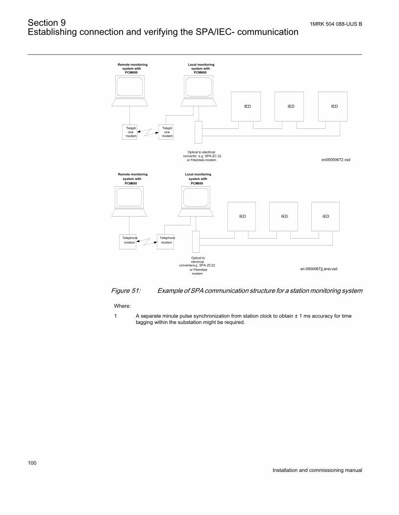
Local monitoringsystem with
PCM600
IED IEDIED
Optical to electricalconverter, e.g. SPA-ZC 22
or Fiberdata modem
Telephone
modem
Telephone
modem
Remote monitoringsystem with
PCM600
en05000672.vsd
IEC05000672 V2 EN
en 05000672_ansi.vsd
Local monitoringsystem with
PCM600
IED IEDIED
converter, e.g . SPA- ZC 22
Optical to electrical
or Fiberdata modem
Telephonemodem
Telephonemodem
Remote monitoringsystem with
PCM600
ANSI05000672 V2 EN
Figure 51: Example of SPA communication structure for a station monitoring system
Where:
1 A separate minute pulse synchronization from station clock to obtain ± 1 ms accuracy for timetagging within the substation might be required.
Section 9 1MRK 504 088-UUS BEstablishing connection and verifying the SPA/IEC- communication
100Installation and commissioning manual
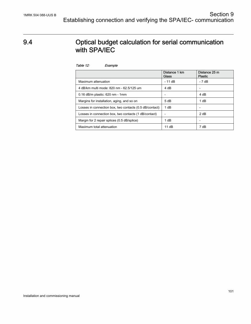
9.4 Optical budget calculation for serial communicationwith SPA/IEC
Table 12: Example
Distance 1 kmGlass
Distance 25 mPlastic
Maximum attenuation - 11 dB - 7 dB
4 dB/km multi mode: 820 nm - 62.5/125 um 4 dB -
0.16 dB/m plastic: 620 nm - 1mm - 4 dB
Margins for installation, aging, and so on 5 dB 1 dB
Losses in connection box, two contacts (0.5 dB/contact) 1 dB -
Losses in connection box, two contacts (1 dB/contact) - 2 dB
Margin for 2 repair splices (0.5 dB/splice) 1 dB -
Maximum total attenuation 11 dB 7 dB
1MRK 504 088-UUS B Section 9Establishing connection and verifying the SPA/IEC- communication
101Installation and commissioning manual

102
Section 10 Establishing connection and verifying theLON communication
About this chapterThis chapter explains how to set up LON communication and how to verify that LONcommunication is up and running.
10.1 Communication via the rear ports
10.1.1 LON communicationLON communication is normally used in substation automation systems. Optical fiberis used within the substation as the physical communication link.
The test can only be carried out when the whole communication system is installed.Thus, the test is a system test and is not dealt with here.
The communication protocol Local Optical Network (LON) is available for 670 IEDseries as an option.
1MRK 504 088-UUS B Section 10Establishing connection and verifying the LON communication
103Installation and commissioning manual
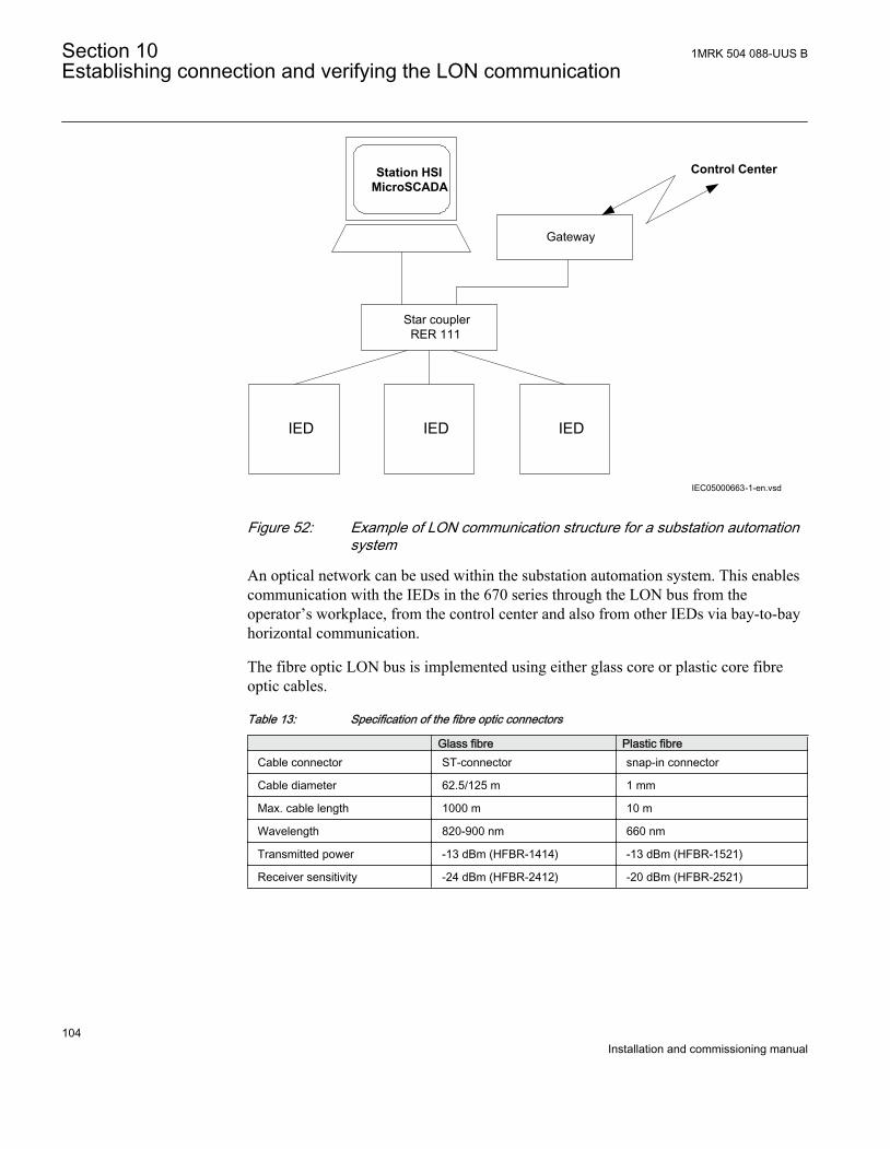
Control Center
IED IEDIED
Gateway
Star couplerRER 111
Station HSIMicroSCADA
IEC05000663-1-en.vsdIEC05000663 V2 EN
Figure 52: Example of LON communication structure for a substation automationsystem
An optical network can be used within the substation automation system. This enablescommunication with the IEDs in the 670 series through the LON bus from theoperator’s workplace, from the control center and also from other IEDs via bay-to-bayhorizontal communication.
The fibre optic LON bus is implemented using either glass core or plastic core fibreoptic cables.
Table 13: Specification of the fibre optic connectors
Glass fibre Plastic fibreCable connector ST-connector snap-in connector
Cable diameter 62.5/125 m 1 mm
Max. cable length 1000 m 10 m
Wavelength 820-900 nm 660 nm
Transmitted power -13 dBm (HFBR-1414) -13 dBm (HFBR-1521)
Receiver sensitivity -24 dBm (HFBR-2412) -20 dBm (HFBR-2521)
Section 10 1MRK 504 088-UUS BEstablishing connection and verifying the LON communication
104Installation and commissioning manual
10.2.1 The LON ProtocolThe LON protocol is specified in the LonTalkProtocol Specification Version 3 fromEchelon Corporation. This protocol is designed for communication in control networksand is a peer-to-peer protocol where all the devices connected to the network cancommunicate with each other directly. For more information of the bay-to-baycommunication, refer to the section Multiple command function.
10.2.2 Hardware and software modulesThe hardware needed for applying LON communication depends on the application,but one very central unit needed is the LON Star Coupler and optical fibres connectingthe star coupler to the IEDs. To interface the IEDs from MicroSCADA, the applicationlibrary LIB670 is required.
The HV Control 670 software module is included in the LIB520 high-voltage processpackage, which is a part of the Application Software Library within MicroSCADAapplications.
The HV Control 670 software module is used for control functions in IEDs in the 670series. This module contains the process picture, dialogues and a tool to generate theprocess database for the control application in MicroSCADA.
Use the LON Network Tool (LNT) to set the LON communication. This is a softwaretool applied as one node on the LON bus. To communicate via LON, the IEDs need toknow
• The node addresses of the other connected IEDs.• The network variable selectors to be used.
This is organized by LNT.
The node address is transferred to LNT via the local HMI by setting the parameterServicePinMsg = Yes. The node address is sent to LNT via the LON bus, or LNT canscan the network for new nodes.
The communication speed of the LON bus is set to the default of 1.25 Mbit/s. This canbe changed by LNT.
The setting parameters for the LON communication are set via the local HMI. Refer tothe technical reference manual for setting parameters specifications.
The path to LON settings in the local HMI is Main menu/Settings/General settings/Communication/SLM configuration/Rear optical LON port
1MRK 504 088-UUS B Section 10Establishing connection and verifying the LON communication
105Installation and commissioning manual
If the LON communication from the IED stops, caused by setting of illegalcommunication parameters (outside the setting range) or by another disturbance, it ispossible to reset the LON port of the IED.
By setting the parameter LONDefault = Yes, the LON communication is reset in theIED, and the addressing procedure can start from the beginning again.
Path in the local HMI under Main menu/Settings/General settings/Communication/SLM configuration/Rear optical LON port
These parameters can only be set with the LON Network Tool (LNT).
Table 14: Setting parameters for the LON communication
Parameter Range Default Unit Parameter descriptionDomainID 0 0 - Domain identification number
SubnetID* 0 - 255Step: 1
0 - Subnet identification number
NodeID* 0 - 127Step: 1
0 - Node identification number
*Can be viewed in the local HMI
Path in the local HMI under Main menu/Settings/General settings/Communication/SLM configuration/Rear optical LON port
These parameters can only be set with the LON Network Tool (LNT).
Table 15: LON node information parameters
Parameter Range Default Unit Parameter descriptionNeuronID* 0 - 12 Not loaded - Neuron hardware identification number in
hexadecimal code
Location 0 - 6 No value - Location of the node
*Can be viewed in the local HMI
Path in the local HMI under Main menu/Settings/General settings/Communication/SLM configuration/Rear optical LON port
Table 16: ADE Non group settings (basic)
Name Values (Range) Unit Step Default DescriptionOperation Disabled
Enabled- - Disabled Operation
TimerClass SlowNormalFast
- - Slow Timer class
Section 10 1MRK 504 088-UUS BEstablishing connection and verifying the LON communication
106Installation and commissioning manual
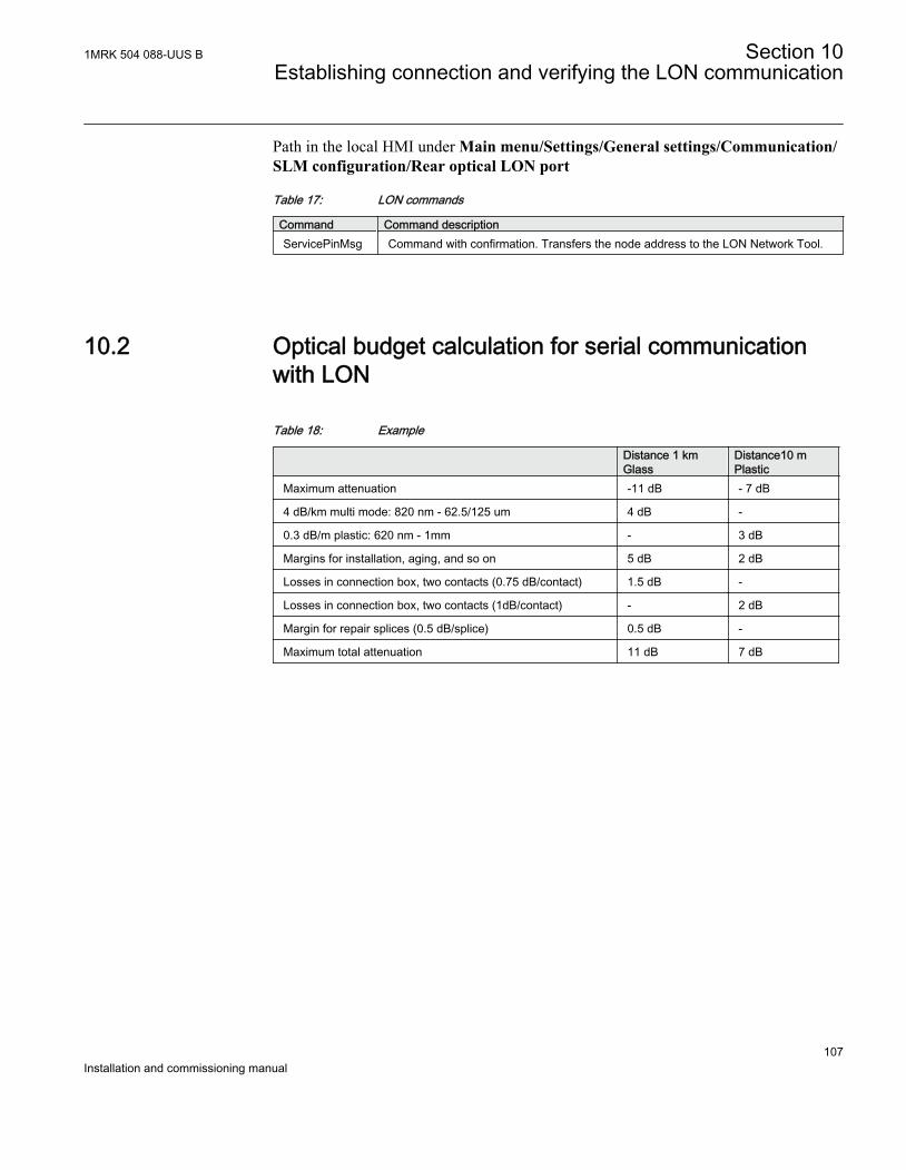
Path in the local HMI under Main menu/Settings/General settings/Communication/SLM configuration/Rear optical LON port
Table 17: LON commands
Command Command descriptionServicePinMsg Command with confirmation. Transfers the node address to the LON Network Tool.
10.2 Optical budget calculation for serial communicationwith LON
Table 18: Example
Distance 1 kmGlass
Distance10 mPlastic
Maximum attenuation -11 dB - 7 dB
4 dB/km multi mode: 820 nm - 62.5/125 um 4 dB -
0.3 dB/m plastic: 620 nm - 1mm - 3 dB
Margins for installation, aging, and so on 5 dB 2 dB
Losses in connection box, two contacts (0.75 dB/contact) 1.5 dB -
Losses in connection box, two contacts (1dB/contact) - 2 dB
Margin for repair splices (0.5 dB/splice) 0.5 dB -
Maximum total attenuation 11 dB 7 dB
1MRK 504 088-UUS B Section 10Establishing connection and verifying the LON communication
107Installation and commissioning manual

108
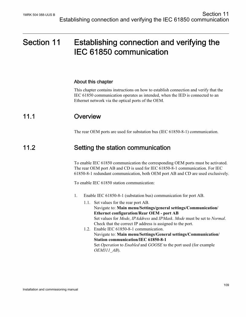
Section 11 Establishing connection and verifying theIEC 61850 communication
About this chapterThis chapter contains instructions on how to establish connection and verify that theIEC 61850 communication operates as intended, when the IED is connected to anEthernet network via the optical ports of the OEM.
11.1 Overview
The rear OEM ports are used for substation bus (IEC 61850-8-1) communication.
11.2 Setting the station communication
To enable IEC 61850 communication the corresponding OEM ports must be activated.The rear OEM port AB and CD is used for IEC 61850-8-1 communication. For IEC61850-8-1 redundant communication, both OEM port AB and CD are used exclusively.
To enable IEC 61850 station communication:
1. Enable IEC 61850-8-1 (substation bus) communication for port AB.1.1. Set values for the rear port AB.
Navigate to: Main menu/Settings/general settings/Communication/Ethernet configuration/Rear OEM - port ABSet values for Mode, IPAddress and IPMask. Mode must be set to Normal.Check that the correct IP address is assigned to the port.
1.2. Enable IEC 61850-8-1 communication.Navigate to: Main menu/Settings/General settings/Communication/Station communication/IEC 61850-8-1Set Operation to Enabled and GOOSE to the port used (for exampleOEM311_AB).
1MRK 504 088-UUS B Section 11Establishing connection and verifying the IEC 61850 communication
109Installation and commissioning manual
11.3 Verifying the communication
Connect your PC to the nearby switch and ping the connected IED and the SubstationMaster PC, to verify that the communication is working (up to the transport layer). If itis possible to see all of them, then they can see each other.
The best way to verify the communication up to the application layer is to
• use a protocol analyzer, for example an Ethereal that is connected to the substationbus, and
• monitor the communication
Section 11 1MRK 504 088-UUS BEstablishing connection and verifying the IEC 61850 communication
110Installation and commissioning manual
Section 12 Configuring the IED and changing settings
About this chapterThis chapter describes how to change IED settings, either through a PC or the localHMI, and download a configuration to the IED in order to make commissioning possible.
The chapter does not contain instructions on how to create a configuration or calculatesettings. Please consult the application manual for further information about how tocalculate settings.
It takes a minimum of three minutes for the IED to save the newsettings, during this time the DC supply must not be turned off.
The IED uses a FLASH disk for storing configuration data and process data likecounters, object states, Local/Remote switch position etc. Since FLASH memory isused, measures have been taken in software to make sure that the FLASH disk is notworn out by too intensive storing of data. These mechanisms make it necessary to thinkabout a couple of issues in order to not loose configuration data, especially atcommissioning time.
After the commissioning is complete, the configuration data is always stored toFLASH, so that is not an issue. But other things, like objects states and the Local/Remote switch position is stored in a slightly different way, where the save of data toFLASH is performed more and more seldom to eliminate the risk of wearing out theFLASH disk. In worst case, the time between saves of this kind of data is around onehour.
This means, that to be absolutely sure that all data have been saved to FLASH, it isnecessary to leave the IED with auxiliary power connected after all the commissioningis done (including setting the Local/Remote switch to the desired position) for at leastone hour after the last commissioning action performed on the IED.
After that time has elapsed, it will be safe to turn the IED off, no data will be lost.
1MRK 504 088-UUS B Section 12Configuring the IED and changing settings
111Installation and commissioning manual
12.1 Overview
The customer specific values for each setting parameter and a configuration file haveto be available before the IED can be set and configured, if the IED is not deliveredwith a configuration.
Use the configuration tools in PCM600 to verify that the IED has the expectedconfiguration. A new configuration is done with the application configuration tool. Thebinary outputs can be selected from a signal list where the signals are grouped undertheir function names. It is also possible to specify a user-defined name for each inputand output signal.
Each function included in the IED has several setting parameters, which have to be setin order to make the IED behave as intended. A factory default value is provided foreach parameter. A setting file can be prepared using the Parameter Setting tool, whichis available in PCM600.
All settings can be
• Entered manually through the local HMI.• Written from a PC, either locally or remotely using SMS/SCS. Front or rear port
communication has to be established before the settings can be written.
12.2 Entering settings through the local HMI
Procedure
1. Set each function included in the IED in the local HMI.2. Browse to the function to be set and enter the appropriate value.3. Find the parameters for each function in the local HMI
The operator's manual is structured in a similar way to the local HMI and provides adetailed guide to the use of the local HMI including paths in the menu structure andbrief explanations of most settings and measurements. See the technical referencemanual for a complete list of setting parameters for each function. Some of theincluded functions may not be used. In this case the user can set the parameterOperation = Off to disable the function.
Section 12 1MRK 504 088-UUS BConfiguring the IED and changing settings
112Installation and commissioning manual
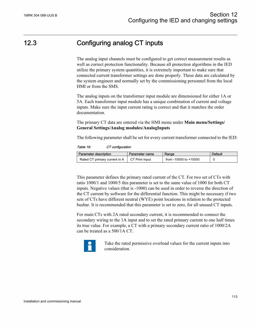
12.3 Configuring analog CT inputs
The analog input channels must be configured to get correct measurement results aswell as correct protection functionality. Because all protection algorithms in the IEDutilize the primary system quantities, it is extremely important to make sure thatconnected current transformer settings are done properly. These data are calculated bythe system engineer and normally set by the commissioning personnel from the localHMI or from the SMS.
The analog inputs on the transformer input module are dimensioned for either 1A or5A. Each transformer input module has a unique combination of current and voltageinputs. Make sure the input current rating is correct and that it matches the orderdocumentation.
The primary CT data are entered via the HMI menu under Main menu/Settings/General Settings/Analog modules/AnalogInputs
The following parameter shall be set for every current transformer connected to the IED:
Table 19: CT configuration
Parameter description Parameter name Range DefaultRated CT primary current in A CT Prim Input from -10000 to +10000 0
This parameter defines the primary rated current of the CT. For two set of CTs withratio 1000/1 and 1000/5 this parameter is set to the same value of 1000 for both CTinputs. Negative values (that is -1000) can be used in order to reverse the direction ofthe CT current by software for the differential function. This might be necessary if twosets of CTs have different neutral (WYE) point locations in relation to the protectedbusbar. It is recommended that this parameter is set to zero, for all unused CT inputs.
For main CTs with 2A rated secondary current, it is recommended to connect thesecondary wiring to the 1A input and to set the rated primary current to one half timesits true value. For example, a CT with a primary secondary current ratio of 1000/2Acan be treated as a 500/1A CT.
Take the rated permissive overload values for the current inputs intoconsideration.
1MRK 504 088-UUS B Section 12Configuring the IED and changing settings
113Installation and commissioning manual
12.4 Downloading settings and configuration from a PC
12.4.1 Writing an application configuration to the IEDWhen writing a configuration to the IED with the application configuration tool, theIED is automatically set in configuration mode. When the IED is set in configurationmode, all functions are blocked. The red LED on the IED flashes, and the green LED islit while the IED is in the configuration mode.
When the configuration is written and completed, the IED is automatically set intonormal mode. For further instructions please refer to the users manuals for PCM600.
Section 12 1MRK 504 088-UUS BConfiguring the IED and changing settings
114Installation and commissioning manual
Section 13 Verifying settings by secondary injection
About this chapterThis chapter describes how to verify that protection functions operate correctly andaccording to their settings. It is preferable that only the tested function is in operation.
13.1 Overview
IED test requirements:
• Calculated settings• Application configuration diagram• Signal matrix (SMT) configuration• Terminal diagram• Technical reference manual• Three-phase test equipment• PCM600
The setting and configuration of the IED must be completed before the testing can start.
The terminal diagram, available in the technical reference manual, is a general diagramof the IED.
Note that the same diagram is not always applicable to each specificdelivery (especially for the configuration of all the binary inputs andoutputs).
Therefore, before testing, check that the available terminal diagram corresponds to theIED.
The technical reference manual contains application and functionality summaries,function blocks, logic diagrams, input and output signals, setting parameters andtechnical data sorted per function.
The test equipment should be able to provide a three-phase supply of voltages andcurrents. The magnitude of voltage and current as well as the phase angle betweenvoltage and current must be variable. The voltages and currents from the testequipment must be obtained from the same source and they must have minimal
1MRK 504 088-UUS B Section 13Verifying settings by secondary injection
115Installation and commissioning manual
harmonic content. If the test equipment cannot indicate the phase angle, a separate phase-angle measuring instrument is necessary.
Prepare the IED for test before testing a particular function. Consider the logic diagramof the tested protection function when performing the test. All included functions in theIED are tested according to the corresponding test instructions in this chapter. Thefunctions can be tested in any order according to user preferences and the testinstructions are therefore presented in alphabetical order. Only the functions that areused (Operation is set to On) should be tested.
The response from a test can be viewed in different ways:
• Binary outputs signals• Service values on the local HMI (logical signals or phasors)• A PC with PCM600 application configuration software in debug mode
All setting groups that are used should be tested.
This IED is designed for a maximum continuous current of four timesthe rated current.
Please observe the measuring accuracy of the IED, the test equipmentand the angular accuracy for both of them.
Please consider the configured logic from the function block to theoutput contacts when measuring the operate time.
13.2 Preparing for test
13.2.1 Preparing the IED to verify settingsIf a test switch is included, start preparation by making the necessary connections tothe test switch. This means connecting the test equipment according to a specific anddesignated IED terminal diagram.
Put the IED into test mode to facilitate the test of individual functions and preventunwanted operation caused by other functions. The test switch should then beconnected to the IED.
Section 13 1MRK 504 088-UUS BVerifying settings by secondary injection
116Installation and commissioning manual
Verify that analog input signals from the analog input module are measured andrecorded correctly by injecting currents and voltages required by the specific IED.
To make testing even more effective PCM600 should be used. PCM600 includes theSignal monitoring tool, which is useful to read of the individual currents and voltages,their amplitudes and phase angles. In addition PCM600 contains the Disturbancehandling tool. The content of reports generated by the Disturbance handling tool can beconfigured which makes the work more efficient. For example, the tool may beconfigured to only show time tagged events and to exclude analog information and so on.
The disturbance report settings must be checked to ensure that indications are correct.
Functions to test, signal and parameter names can be found in the technical referencemanual. The correct initiation of the disturbance recorder is made on start and/orrelease or trip from a function. Also check that the wanted recordings of analogue (realand calculated) and binary signals are achieved.
Parameters can be entered into different setting groups. Make sure totest functions for the same parameter setting group. If needed the testsmust be repeated for all different setting groups used. The differencebetween testing the first parameter setting group and the remaining isthat there is no need for testing the connections.
Observe during testing that the right method for testing must be used that correspondsto the actual parameters set in the activated parameter setting group.
Set and configure the function(s) before the testing can start. Most functions are highlyflexible and permit a choice of functional and tripping modes. The various modes arechecked at the factory as part of the design verification. In certain cases only modeswith a high probability of coming into operation need to be checked whencommissioned to verify the configuration and settings.
13.2.2 Preparing the connection to the test equipmentThe IED can be equipped with a test switch of type RTXP8, RTXP18 or RTXP24 orFT. The test switch and its associated test plug handles are a part of the COMBITESTor FT system of ABB, which provides secure and convenient testing of the IED.
When using the COMBITEST, preparations for testing are automatically carried out inthe proper sequence, that is for example, blocking of tripping circuits, short circuitingof CT’s, opening of voltage circuits, making IED terminals available for secondaryinjection). Terminals 1 and 8, 1 and 18 as well as 1 and 12 of the test switches RTXP8,RTXP18 and RTXP24 respectively are not disconnected as they supply DC power tothe protection IED. When FT switch is used for testing, care shall be exercised to openthe tripping circuit, ahead of manipulating the CT fingers.
1MRK 504 088-UUS B Section 13Verifying settings by secondary injection
117Installation and commissioning manual
The RTXH test-plug handle leads may be connected to any type of test equipment orinstrument. When a number of protection IEDs of the same type are tested, the test-plug handle only needs to be moved from the test switch of one protection IED to thetest switch of the other, without altering previous connections.
Use COMBITEST test system to prevent unwanted tripping when the handle iswithdrawn, since latches on the handle secure it in the half withdrawn position. In thisposition, all voltages and currents are restored and any reenergizing transients aregiven a chance to decay before the trip circuits are restored. When the latches arereleased, the handle can be completely withdrawn from the test switch, restoring thetrip circuits to the protection IED.
If a test switch is not used, take measures according to provided circuit diagrams.
Never disconnect the secondary connection of a current transformercircuit without short-circuiting the transformer's secondary winding.Operating a current transformer with the secondary winding open willcause a massive potential build up that may damage the transformerand injure humans.
13.2.3 Activating test modeThe IED shall be put into test mode before testing. Test mode blocks all functions inthe IED and the individual functions to be tested can be unblocked to prevent unwantedoperation caused by other functions. In this way, it is possible to test slower back-upmeasuring functions without the interference from faster measuring functions. Testmode is indicated when the yellow Start LED flashes.
Procedure
1. Browse to the TestMode menu and press E.The TestMode menu is found on the local HMI under Main menu/Test/IED testmode/TestMode
2. Use the up and down arrows to choose On and press E.3. Press the left arrow to exit the menu.
The dialog box Save changes appears.4. Choose Yes, press E and exit the menu.
The yellow pickupLED above the LCD will start flashing when the IED is in testmode.
13.2.4 Connecting test equipment to the IEDConnect the test equipment according to the IED specific connection diagram.
Section 13 1MRK 504 088-UUS BVerifying settings by secondary injection
118Installation and commissioning manual
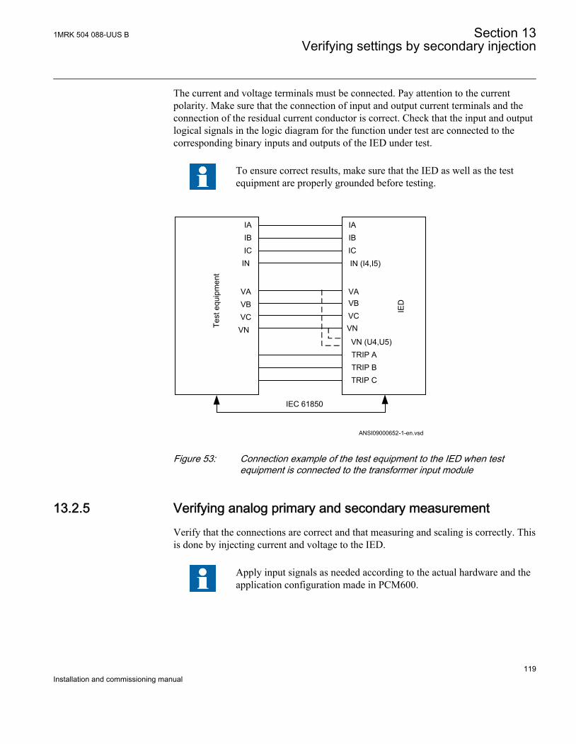
The current and voltage terminals must be connected. Pay attention to the currentpolarity. Make sure that the connection of input and output current terminals and theconnection of the residual current conductor is correct. Check that the input and outputlogical signals in the logic diagram for the function under test are connected to thecorresponding binary inputs and outputs of the IED under test.
To ensure correct results, make sure that the IED as well as the testequipment are properly grounded before testing.
IAIBICIN
VAVBVCVN
IAIBIC
VA
IN (I4,I5)
TRIP ATRIP BTRIP C
Test
equ
ipm
ent
IED
ANSI09000652-1-en.vsd
VBVCVN
VN (U4,U5)
IEC 61850
ANSI09000652 V1 EN
Figure 53: Connection example of the test equipment to the IED when testequipment is connected to the transformer input module
13.2.5 Verifying analog primary and secondary measurementVerify that the connections are correct and that measuring and scaling is correctly. Thisis done by injecting current and voltage to the IED.
Apply input signals as needed according to the actual hardware and theapplication configuration made in PCM600.
1MRK 504 088-UUS B Section 13Verifying settings by secondary injection
119Installation and commissioning manual
1. Inject a symmetrical three-phase voltage and current at rated value.2. Compare the injected value with the measured values.
The voltage and current phasor menu in the local HMI is located under Mainmenu/Measurements/Analog primary values and Main menu/Measurements/Analog secondary values.
3. Compare the frequency reading with the set frequency and the direction of thepower.The frequency and active power are located under Main menu/Measurements/Monitoring/ServiceValues(MMXU)/SVRx. Then navigate to the bottom of thelist to find the frequency.
4. Inject an unsymmetrical three phase voltage and current, to verify that phases arecorrectly connected.
If some setting deviates check the analog input settings under
Main menu/Settings/General settings/Analog modules
13.2.6 Releasing the function to be testedRelease or unblock the function to be tested. This is done to ensure that only thefunction or the chain of functions to be tested are in operation and that other functionsare prevented from operating. The user can release the tested function(s) by setting thecorresponding Blocked parameter under Function test modes to No in the local HMI.
When testing a function in this blocking feature, remember that not only the actualfunction must be activated, but the whole sequence of interconnected functions (frommeasuring inputs to binary output contacts), including logic and so on. Before startinga new test mode session the user should scroll through every function to ensure thatonly the function to be tested (and the interconnected ones) have the parametersBlocked and eventually EvDisable are set to No and Yes respectively. Remember that afunction is also blocked if the BLOCK input signal on the corresponding functionblock is active, which depends on the configuration. Ensure that the logical status ofthe BLOCK input signal is equal to 0 for the function to be tested. Event functionblocks can also individually be blocked to ensure that no events are reported to aremote station during the test. This is done by setting the parameter EvDisable to Yes.
Any function is blocked if the corresponding setting in the local HMIunder Main menu/Test/Function test modes menu remains On, that isthe parameter Blocked is set to Yes and the parameter TestMode underMain menu/Test/IED test mode remains active. All functions thatwere blocked or released from a previous test mode session, that is theparameter Test mode is set to On, are reset when a new test modesession is started.
Section 13 1MRK 504 088-UUS BVerifying settings by secondary injection
120Installation and commissioning manual
Procedure
1. Browse to the Function test modes menu.The Function test modes menu is located in the local HMI under Main menu/Test/Function test modes.
2. Browse to the function instance that should be released.3. Set parameter Blocked for the selected function to Yes.
13.2.7 Disturbance report
13.2.7.1 Introduction
The following sub-functions are included in the disturbance report function:
• Disturbance recorder• Event list• Event recorder• Trip value recorder• Indications
If the disturbance report is set on, then its sub-functions are also set up and so it is notpossible to only switch these sub-functions off. The disturbance report function isswitched off (parameter Operation = Off) in PCM600 or the local HMI under Mainmenu/Settings/General settings/Monitoring/DisturanceReport/DisturbanceReport(RDRE).
13.2.7.2 Disturbance report settings
When the IED is in test mode, the disturbance report can be made active or inactive. Ifthe disturbance recorder is turned on during test mode, recordings will be made. Whentest mode is switched off all recordings made during the test session are cleared.
Setting OpModeTest for the control of the disturbance recorder during test mode arelocated on the local HMI under Main menu/Settings/General settings/Monitoring/DisturbanceReport/DisturbanceReport(RDRE).
13.2.7.3 Disturbance recorder (DR)
A Manual Trig can be started at any time. This results in a recording of the actualvalues from all recorded channels.
The Manual Trig can be initiated in two ways:
1. From the local HMI under Main menu/Disturbance records.
1MRK 504 088-UUS B Section 13Verifying settings by secondary injection
121Installation and commissioning manual
1.1. Enter on the row at the bottom of the HMI called Manual trig.The newly performed manual trig will result in a new row.
1.2. Navigate to General information or to Trip values to obtain more detailedinformation.
2. Open the Disturbance handling tool for the IED in the plant structure in PCM600.2.1. Right-click and select Execute manual Trig in the window Available
recordings in IED.2.2. Read the required recordings from the IED.2.3. Refresh the window Recordings and select a recording.2.4. Right-click and select Create Report or Open With to export the recordings
to any disturbance analyzing tool that can handle Comtrade formatted files.
Evaluation of the results from the disturbance recording function requires access to aPC either permanently connected to the IED or temporarily connected to the Ethernetport (RJ-45) on the front. The PCM600 software package must be installed in the PC.
Disturbance upload can be performed by the use of PCM600 or by any third party toolwith IEC 61850 protocol. Reports can automatically be generated from PCM600.Disturbance files can be analyzed by any tool reading Comtrade formatted disturbancefiles.
13.2.7.4 Event recorder (ER) and Event list (EL)
The result from the event recorder and event list can be viewed on the local HMI or,after upload, in PCM600 as follows:
1. on the local HMI under Main menu/Events, or in more details via2. the Event Viewer in PCM600.
The internal FIFO register of all events will appear when the event viewer islaunched.
When the IED is brought into normal service it is recommended to delete all eventsresulting from commissioning tests to avoid confusion in future fault analysis. Allevent in the IED can be cleared in the local HMI under Main Menu//Reset/Resetinternal event list or Main menu/Reset/Reset process event list. It is not possible toclear the event lists from PCM600.
When testing binary inputs, the event list (EL) might be used instead. No uploading oranalyzing of registrations is then needed since the event list keeps running,independent of start of disturbance registration.
Section 13 1MRK 504 088-UUS BVerifying settings by secondary injection
122Installation and commissioning manual
13.2.8 Identifying the function to test in the technical reference manualUse the technical reference manual (to identify function blocks, logic diagrams, inputand output signals, setting parameters and technical data.
13.2.9 Exit test modeThe following procedure is used to return to normal operation.
Procedure
1. Navigate to the test mode folder.2. Change the 'On' setting to 'Off'. Press the 'E' key and the left arrow key.3. Answer 'YES', press the 'E' key and exit the menus.
13.3 Basic IED functions
13.3.1 Parameter setting group handling SETGRPSPrepare the IED for verification of settings as outlined in section "Overview" andsection "Preparing for test" in this chapter.
13.3.1.1 Verifying the settings
1. Check the configuration of binary inputs that control the selection of the activesetting group.
2. Browse to the ActiveGroup menu to achieve information about the active settinggroup.The ActiveGroup menu is located on the local HMI underMain menu/Test/Function status/Setting groups/ActiveGroup
3. Connect the appropriate dc voltage to the corresponding binary input of the IEDand observe the information presented on the local HMI.The displayed information must always correspond to the activated input.
4. Check that the corresponding output indicates the active group.Operating procedures for the PC aided methods of changing the active settinggroups are described in the corresponding PCM600 documents and instructionsfor the operators within the SCS are included in the SCS documentation.
1MRK 504 088-UUS B Section 13Verifying settings by secondary injection
123Installation and commissioning manual
13.3.1.2 Completing the test
Continue to test another function or end the test by changing the Test mode setting toOff. Restore connections and settings to their original values, if they were changed fortesting purposes.
13.4 Differential protection
13.4.1 Transformer differential protection T2WPDIF (87T) andT3WPDIF (87T)Prepare the IED for verification of settings as outlined in section "Overview" andsection "Preparing for test" in this chapter.
13.4.1.1 Verifying the settings
Procedure
1. Go to Main menu/Test/Function Test Mode/Differential protection and makesure that the restricted earth fault protection, low impedance function REFPDIF(87N) is set to Off and that the four step residual overcurrent function EF4PTOC(51N/67N) under Main menu/Test/Function Test Mode/Current protection isset to Off, since they are configured to the same current transformer inputs as thetransformer differential protection. Make sure that the transformer differentialfunctions T2WPDIF (87T) and T3WPDIF (87T) are unblocked.
2. Connect the test set for injection of three-phase currents to the current terminalsof the IED, which are connected to the CTs on the HV side of the power transformer.
3. Increase the current in phase A until the protection function operates and note theoperating current.
4. Check that trip and alarm contacts operate according to the configuration logic.5. Decrease the current slowly from operate value and note the reset value.
Depending of the power transformer phase shift/vector group (Yd (Wye/Delta)and so on), the single-phase injection current may appear as differential current inone or two phases and the operating value of the injected single-phase currentwill be different.
6. Check in the same way the function by injecting current in phases B and Crespectively.
7. Inject a symmetrical three-phase current and note the operate value.8. Connect the timer and set the current to twice the operate value.9. Switch on the current and note the operate time.
Section 13 1MRK 504 088-UUS BVerifying settings by secondary injection
124Installation and commissioning manual
10. Check in the same way the functioning of the measuring circuits connected to theCTs on the LV side and other current inputs to the transformer differentialprotection.
11. Finally check that trip information is stored in the event menu.
Information on how to use the event menu is found in theoperator’s manual.
12. If available on the test set a second harmonic current of about 20% (assumes 15%setting on I1/I2ratio parameter) can be added to the fundamental tone in phase A.Increase the current in phase A above the pickup value measured in point 13.Repeat to test with current injection in phases B and C respectively.The balancing of currents flowing into and out of the differential zone is checkedby primary injection testing, see section "Primary injection testing".Fifth harmonic blocking can be tested in a similar way.
For more detailed formulas please refer to the application manual.
13.4.1.2 Completing the test
Continue to test another function or end the test by changing the Test mode setting toOff. Restore connections and settings to their original values, if they were changed fortesting purposes.
13.4.2 Restricted earth fault protection, low impedance REFPDIF(87N)Prepare the IED for verification of settings as outlined in section "Overview" andsection "Preparing for test" in this chapter.
13.4.2.1 Verifying the settings
Procedure
1. Connect the test set for single-phase current injection to the protection terminalsconnected to the CT in the power transformer neutral-to-ground circuit.
2. Increase the injection current and note the operating value of the protectionfunction.
3. Check that all trip and pickup contacts operate according to the configuration logic.4. Decrease the current slowly from operate value and note the reset value.
1MRK 504 088-UUS B Section 13Verifying settings by secondary injection
125Installation and commissioning manual
5. Connect the timer and set the current to twice the operate value.6. Switch on the current and note the operate time.7. Connect the test set to terminal A and neutral of the three-phase current input
configured to REFPDIF(87N) . Also inject a current higher than half the Idminsetting in the neutral-to-ground circuit with the same phase angle and withpolarity corresponding to an internal fault.
8. Increase the current injected in A, and note the operate value. Decrease thecurrent slowly and note the reset value.
9. Inject current into terminals B and C in the same way as in point 7 above and notethe operate and reset values.
10. Inject a current equal to 10% of rated current into terminal A.11. Inject a current in the neutral-to-ground circuit with the same phase angle and
with polarity corresponding to an external fault.12. Increase the current to five times the operating value and check that the protection
does not operate.13. Finally check that trip information is stored in the event menu.
13.4.2.2 Completing the test
Continue to test another function or end the test by changing the Test mode setting toOff. Restore connections and settings to their original values, if they were changed fortesting purposes.
13.4.3 High impedance differential protection HZPDIF (87)Prepare the IED for verification of settings as outlined in section "Overview" andsection "Preparing for test" in this chapter.
13.4.3.1 Verifying the settings
1. Connect single-phase or three-phase test set to inject the operating voltage. Theinjection shall be on the primary side of the stabilizing resistor.
As the operating voltage is adjusted on the stabilizing resistor andwith the setting of the resistor value in the function this isessential for the measurement of the expected value. Normally a
Section 13 1MRK 504 088-UUS BVerifying settings by secondary injection
126Installation and commissioning manual
slightly higher operating value is no problem as the sensitivity isnot influenced much.
2. Connect the trip contact to the test set to stop the test set for measurement of triptimes below.
3. Increase the voltage and make note of the operate value Pickup. This is done withmanual test and without trip of the test set.
4. Reduce the voltage slowly and make note of the reset value. The reset value mustbe high for this function.
5. Check the operating time by injecting a voltage corresponding to 1.2 · Pickuplevel. Make note of the measured trip time.
6. If required, verify the trip time at another voltage. Normally 2 · Pickup is selected.7. If used, measure the alarm level operating value. Increase the voltage and make
note of the operate value AlarmPickup. This is done with manual test and withouttrip of the test set.
8. Measure the operating time on the alarm output by connecting the stop of the testset to an output from tAlarm. Inject a voltage 1.2 · AlarmPickup and measure thealarm time.
9. Check that trip and alarm outputs operate accordingly to the configuration logic.10. Finally check that pickup and alarm information is stored in the event menu and
if a serial connection to the SA is available verify that the correct and only therequired signals are presented on the local HMI and on the SCADA system.
Information on how to use the event menu is found in the operator'smanual.
13.4.3.2 Completing the test
Continue to test another function or end the test by changing the Test mode setting toOff. Restore connections and settings to their original values, if they were changed fortesting purposes.
13.5 Impedance protection
13.5.1 Distance protection zones, quadrilateral characteristicZMQPDIS (21)Prepare the IED for verification of settings as outlined in section "Overview" andsection "Preparing for test" in this chapter.
1MRK 504 088-UUS B Section 13Verifying settings by secondary injection
127Installation and commissioning manual
Consider releasing Zone 1, the Phase selection with load encroachment, quadrilateralcharacteristic (FDPSDPIS) and the tripping logic SMPPTRC. If the autorecloser is notreleased and in service, trip will always be three phase.
Measure operating characteristics during constant current conditions. Keep themeasured current as close as possible to its rated value or lower. But make sure it ishigher than 30% of the rated current.
Ensure that the maximum continuous current in an IED does not exceed four times itsrated value, if the measurement of the operating characteristics runs under constantvoltage conditions.
The test procedure has to take into consideration that the shaped load encroachmentcharacteristic is active. It is therefore necessary to check the setting. To verify thesettings with the shaped load encroachment characteristic the test should be carried outaccording to figures 54 and 55 and tables 20 and 21. In cases where the loadencroachment characteristic is activated tests according to the adjusted figures shouldbe carried out.
To verify the settings for the operating points according to the following fault typesshould be tested:
• One phase-to-phase fault• One phase-to-earth fault
The shape of the operating characteristic depends on the values of the setting parameters.
The figures illustrating the characteristic for the distance protectionfunction can be used for settings with and without load encroachment.The solid lines designate the diagram applicable when the load currentcompensation operationLdCom parameter is set to 1 (On). This is thedefault setting. The solid line and all test points except 13 are valid forthis setting.When it is set to 0 (Off) then the dotted lines and test point 13 are valid.Test points 5, 6, and 7 are not valid for this measurement.
Section 13 1MRK 504 088-UUS BVerifying settings by secondary injection
128Installation and commissioning manual
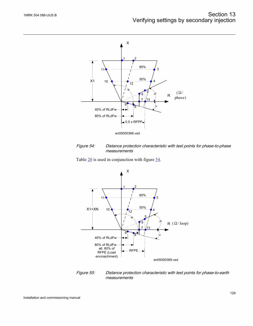
X1
R
X
(Ω/phase)
50%
80%
1 2
3
4
567
89
10
11
80% of RLdFw
40% of RLdFw
0.5 x RFPP
12
en05000368.vsd
13
a
bc
IEC05000368 V1 EN
Figure 54: Distance protection characteristic with test points for phase-to-phasemeasurements
Table 20 is used in conjunction with figure 54.
X1+XN
R
X
(Ω/ loop)
50%
80%
1 2
3
4
5
67
89
10
11
80% of RLdFw
40% of RLdFw
RFPE
12
en05000369.vsd
13
a
cb
alt. 80% ofRFPE (Load
encroachment)
IEC05000369 V1 EN
Figure 55: Distance protection characteristic with test points for phase-to-earthmeasurements
1MRK 504 088-UUS B Section 13Verifying settings by secondary injection
129Installation and commissioning manual
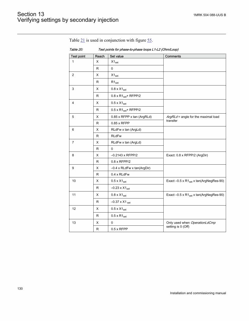
Table 21 is used in conjunction with figure 55.
Table 20: Test points for phase-to-phase loops L1-L2 (Ohm/Loop)
Test point Reach Set value Comments1 X X1set
R 0
2 X X1set
R R1set
3 X 0.8 x X1set
R 0.8 x R1set+ RFPP/2
4 X 0.5 x X1set
R 0.5 x R1set+ RFPP/2
5 X 0.85 x RFPP x tan (ArgRLd) ArgRLd = angle for the maximal loadtransfer
R 0.85 x RFPP
6 X RLdFw x tan (ArgLd)
R RLdFw
7 X RLdFw x tan (ArgLd)
R 0
8 X –0.2143 x RFPP/2 Exact: 0.8 x RFPP/2 (ArgDir)
R 0.8 x RFPP/2
9 X –0.4 x RLdFw x tan(ArgDir)
R 0.4 x RLdFw
10 X 0.5 x X1set Exact –0.5 x R1set x tan(ArgNegRes-90)
R –0.23 x X1set
11 X 0.8 x X1set Exact –0.5 x R1set x tan(ArgNegRes-90)
R –0.37 x X1 set
12 X 0.5 x X1set
R 0.5 x R1set
13 X 0 Only used when OperationLdCmpsetting is 0 (Off)
R 0.5 x RFPP
Section 13 1MRK 504 088-UUS BVerifying settings by secondary injection
130Installation and commissioning manual
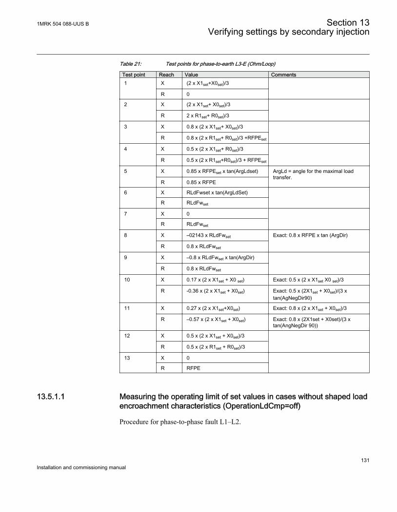
Table 21: Test points for phase-to-earth L3-E (Ohm/Loop)
Test point Reach Value Comments1 X (2 x X1set+X0set)/3
R 0
2 X (2 x X1set+ X0set)/3
R 2 x R1set+ R0set)/3
3 X 0.8 x (2 x X1set+ X0set)/3
R 0.8 x (2 x R1set+ R0set)/3 +RFPEset
4 X 0.5 x (2 x X1set+ R0set)/3
R 0.5 x (2 x R1set+R0set)/3 + RFPEset
5
X 0.85 x RFPEset x tan(ArgLdset) ArgLd = angle for the maximal loadtransfer.
R 0.85 x RFPE
6 X RLdFwset x tan(ArgLdSet)
R RLdFwset
7 X 0
R RLdFwset
8 X –02143 x RLdFwset Exact: 0.8 x RFPE x tan (ArgDir)
R 0.8 x RLdFwset
9 X –0.8 x RLdFwset x tan(ArgDir)
R 0.8 x RLdFwset
10 X 0.17 x (2 x X1set + X0 set) Exact: 0.5 x (2 x X1set X0 set)/3
R -0.36 x (2 x X1set + X0set) Exact: 0.5 x (2X1set + X0set)/(3 xtan(AgNegDir90)
11 X 0.27 x (2 x X1set+X0set) Exact: 0.8 x (2 x X1set + X0set)/3
R –0.57 x (2 x X1set + X0set) Exact: 0.8 x (2X1set + X0set)/(3 xtan(AngNegDir 90))
12 X 0.5 x (2 x X1set + X0set)/3
R 0.5 x (2 x R1set + R0set)/3
13 X 0
R RFPE
13.5.1.1 Measuring the operating limit of set values in cases without shaped loadencroachment characteristics (OperationLdCmp=off)
Procedure for phase-to-phase fault L1–L2.
1MRK 504 088-UUS B Section 13Verifying settings by secondary injection
131Installation and commissioning manual
1. Subject the IED to healthy normal load conditions for at least two seconds.2. Apply the fault condition and slowly decrease the measured impedance to find
the operating value of the phase-to-phase fault for zone 1 according to test point 1in figure 54 and table 20. Compare the result of the measurement with the set value.
3. Repeat steps 1 to 2 to find the operating value for test point 2, 3 in table20 and theoperating value for the phase-to-earth loop according to test point 1, 2, 3 in table21.Observe that the zones that are not tested have to be blocked and the zone that istested has to be released.
4. Repeat steps 1 to 3 above to find the operating value for the phase-to-earth fault L3-E according to figure 55 and table 21
Test points 8 and 9 are intended to test the directional lines ofimpedance protection. Since directionality is a common functionfor all 5 measuring zones, it is only necessary to test points 6, 7, 8and 9 once, in the forward direction (the largest reverse zone canbe used to facilitate the test) in order to test the accuracy ofdirectionality (directional angles). Directional functionality testing(trip inside, no-trip outside) should always be carried for allimpedance zones set with directionality (forward or reverse).
13.5.1.2 Measuring the operate time of distance protection zones
Procedure
1. Subject the IED to healthy normal load conditions for at least two seconds.2. Apply the fault condition to find the operating time for the phase-to-phase fault
according to test point 10 in figure 54 and table 20 for zone 1. Compare the resultof the measurement with the setting t1PP.
3. Repeat steps 1 to 2 to find the operating time for the phase-to-earth faultaccording to test point 10 in figure 55 and table 21. Compare the result of themeasurement with the setting t1PE.
4. Repeat steps 1 to 2 to find the operating time for all other used measuring zones.Observe that the zones that are not tested have to be blocked and the zone that istested has to be released.When the load shaped characteristic is activated (OperationLdCmp=On) the testpoint for phase-to-phase faults is 12 in figure 54 and table 20 and for phase-earthfaults according to P12 in figure 55 and table 21.
13.5.1.3 Completing the test
Continue to test another function or end the test by changing the test mode setting to off.
Section 13 1MRK 504 088-UUS BVerifying settings by secondary injection
132Installation and commissioning manual
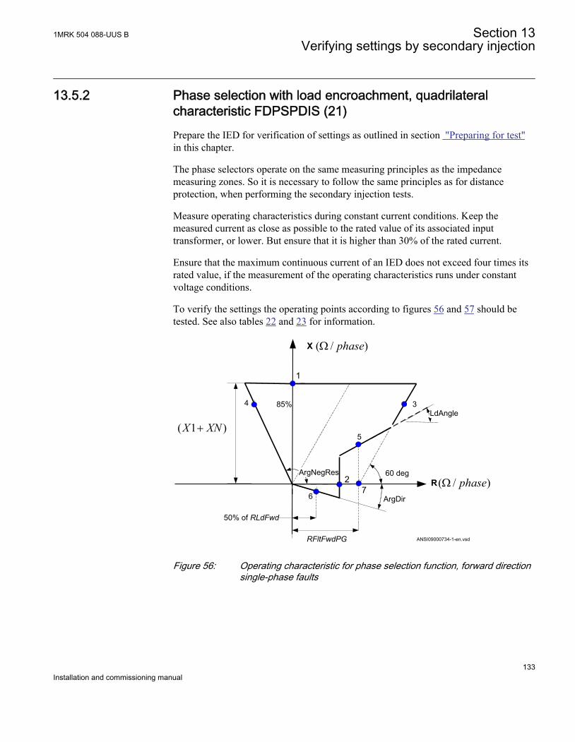
13.5.2 Phase selection with load encroachment, quadrilateralcharacteristic FDPSPDIS (21)Prepare the IED for verification of settings as outlined in section "Preparing for test"in this chapter.
The phase selectors operate on the same measuring principles as the impedancemeasuring zones. So it is necessary to follow the same principles as for distanceprotection, when performing the secondary injection tests.
Measure operating characteristics during constant current conditions. Keep themeasured current as close as possible to the rated value of its associated inputtransformer, or lower. But ensure that it is higher than 30% of the rated current.
Ensure that the maximum continuous current of an IED does not exceed four times itsrated value, if the measurement of the operating characteristics runs under constantvoltage conditions.
To verify the settings the operating points according to figures 56 and 57 should betested. See also tables 22 and 23 for information.
ArgDir
R
X
RFltFwdPG
60 deg
1
3
)1( XNX +5
2
4
ArgNegRes
85%LdAngle
50% of RLdFwd
6
ANSI09000734-1-en.vsd
)/( phaseW
)/( phaseW7
ANSI09000734 V1 EN
Figure 56: Operating characteristic for phase selection function, forward directionsingle-phase faults
1MRK 504 088-UUS B Section 13Verifying settings by secondary injection
133Installation and commissioning manual
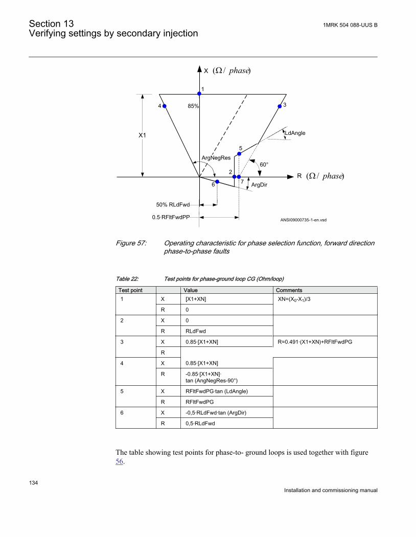
X1
R
X
85%
1
3
5
2
6
4
50% RLdFwd
ArgNegRes
0.5·RFltFwdPP
LdAngle
ANSI09000735-1-en.vsd
ArgDir
60°
)/( phaseW
)/( phaseW7
ANSI09000735 V1 EN
Figure 57: Operating characteristic for phase selection function, forward directionphase-to-phase faults
Table 22: Test points for phase-ground loop CG (Ohm/loop)
Test point Value Comments1 X [X1+XN] XN=(X0-X1)/3
R 0
2 X 0
R RLdFwd
3 X 0.85·[X1+XN] R≈0.491·(X1+XN)+RFltFwdPG
R
4 X 0.85·[X1+XN]
R -0.85·[X1+XN]·tan (AngNegRes-90°)
5 X RFltFwdPG·tan (LdAngle)
R RFltFwdPG
6 X -0,5·RLdFwd·tan (ArgDir)
R 0,5·RLdFwd
The table showing test points for phase-to- ground loops is used together with figure56.
Section 13 1MRK 504 088-UUS BVerifying settings by secondary injection
134Installation and commissioning manual
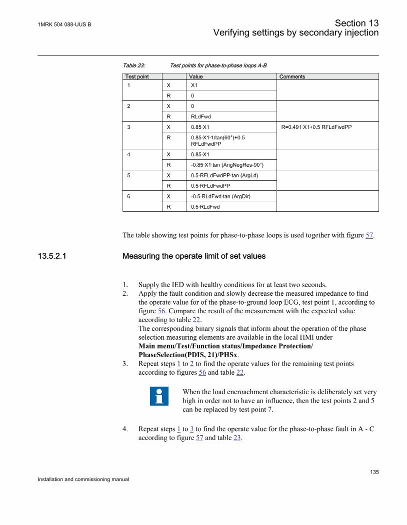
Table 23: Test points for phase-to-phase loops A-B
Test point Value Comments1 X X1
R 0
2 X 0
R RLdFwd
3 X 0.85·X1 R=0.491·X1+0.5 RFLdFwdPP
R 0.85·X1·1/tan(60°)+0.5RFLdFwdPP
4 X 0.85·X1
R -0.85·X1·tan (AngNegRes-90°)
5 X 0.5·RFLdFwdPP·tan (ArgLd)
R 0.5·RFLdFwdPP
6 X -0.5·RLdFwd·tan (ArgDir)
R 0.5·RLdFwd
The table showing test points for phase-to-phase loops is used together with figure 57.
13.5.2.1 Measuring the operate limit of set values
1. Supply the IED with healthy conditions for at least two seconds.2. Apply the fault condition and slowly decrease the measured impedance to find
the operate value for of the phase-to-ground loop ECG, test point 1, according tofigure 56. Compare the result of the measurement with the expected valueaccording to table 22.The corresponding binary signals that inform about the operation of the phaseselection measuring elements are available in the local HMI underMain menu/Test/Function status/Impedance Protection/PhaseSelection(PDIS, 21)/PHSx.
3. Repeat steps 1 to 2 to find the operate values for the remaining test pointsaccording to figures 56 and table 22.
When the load encroachment characteristic is deliberately set veryhigh in order not to have an influence, then the test points 2 and 5can be replaced by test point 7.
4. Repeat steps 1 to 3 to find the operate value for the phase-to-phase fault in A - Caccording to figure 57 and table 23.
1MRK 504 088-UUS B Section 13Verifying settings by secondary injection
135Installation and commissioning manual
When the load encroachment characteristic is deliberately set veryhigh in order not to have an influence, then the test points 2 and 5can be replaced by test point 7.
13.5.2.2 Completing the test
Continue to test another function or end the test by changing the Test mode setting toOff. Restore connections and settings to their original values, if they were changed fortesting purposes.
13.5.3 Full scheme distance protection, mho characteristic ZMHPDIS(21)Prepare the IED for verification of settings as outlined in section "Overview" andsection "Preparing for test" in this chapter. Consider releasing of the zone to be testedby setting the phase selector FDPSPDIS to On.
The programming of the autorecloser function SMBRREC (79) will determine if three-phase or single-phase trip will be initiated as result of the test.
Keep the current constant when measuring operating characteristics. Keep the currentas close as possible to its rated value or lower. But make sure it is higher than 30% ofthe rated current.
Ensure that the maximum continuous current in an IED does not exceed four times itsrated value, if the measurement of the operating characteristics runs under constantvoltage conditions.
To verify the mho characteristic, at least two points should be tested.
In the following, three test points are proposed. The mho characteristic always goesthrough the origin, which automatically gives a fourth point for the characteristic.
13.5.3.1 Phase-to-phase faults
Section 13 1MRK 504 088-UUS BVerifying settings by secondary injection
136Installation and commissioning manual
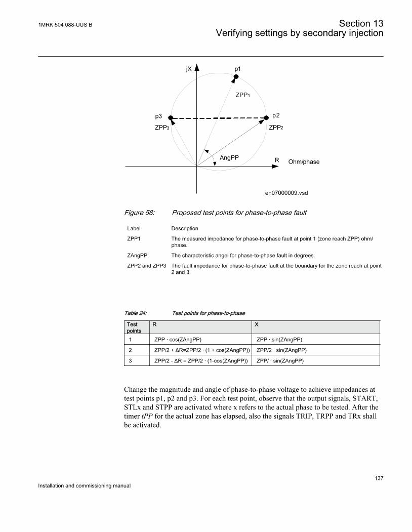
AngPP
ZPP1
p1
p2
ZPP2
p3
ZPP3
Ohm/phaseR
jX
en07000009.vsdIEC07000009 V2 EN
Figure 58: Proposed test points for phase-to-phase fault
Label Description
ZPP1 The measured impedance for phase-to-phase fault at point 1 (zone reach ZPP) ohm/phase.
ZAngPP The characteristic angel for phase-to-phase fault in degrees.
ZPP2 and ZPP3 The fault impedance for phase-to-phase fault at the boundary for the zone reach at point2 and 3.
Table 24: Test points for phase-to-phase
Testpoints
R X
1 ZPP · cos(ZAngPP) ZPP · sin(ZAngPP)
2 ZPP/2 + ΔR=ZPP/2 · (1 + cos(ZAngPP)) ZPP/2 · sin(ZAngPP)
3 ZPP/2 - ΔR = ZPP/2 · (1-cos(ZAngPP)) ZPP/ · sin(ZAngPP)
Change the magnitude and angle of phase-to-phase voltage to achieve impedances attest points p1, p2 and p3. For each test point, observe that the output signals, START,STLx and STPP are activated where x refers to the actual phase to be tested. After thetimer tPP for the actual zone has elapsed, also the signals TRIP, TRPP and TRx shallbe activated.
1MRK 504 088-UUS B Section 13Verifying settings by secondary injection
137Installation and commissioning manual
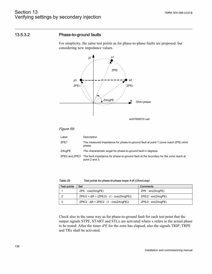
13.5.3.2 Phase-to-ground faults
For simplicity, the same test points as for phase-to-phase faults are proposed, butconsidering new impedance values.
ZAngPE
ZPE1
p1
p2
ZPE2
p3
ZPE3
Ohm/phaseR
jX
en07000010.vsd
IEC07000010 V2 EN
Figure 59:
Label Description
ZPE1 The measured impedance for phase-to-ground fault at point 1 (zone reach ZPE) ohm/phase.
ZAngPE The characteristic angel for phase-to-ground fault in degrees.
ZPE2 and ZPE3 The fault impedance for phase-to-ground fault at the boundary for the zone reach atpoint 2 and 3.
Table 25: Test points for phase-to-phase loops A-B (Ohm/Loop)
Test points Set Comments1 ZPE · cos(ZAngPE) ZPE · sin(ZAngPE)
2 ZPE/2 + ΔR = (ZPE/2) · (1 - cos(ZAngPE)) ZPE/2 · sin(ZAngPE)
3 ZPE/2 - ΔR = ZPE/2 · (1 - cos(ZAngPE)) ZPE/2 · sin(ZAngPE)
Check also in the same way as for phase-to-ground fault for each test point that theoutput signals STPE, START and STLx are activated where x refers to the actual phaseto be tested. After the timer tPE for the zone has elapsed, also the signals TRIP, TRPEand TRx shall be activated.
Section 13 1MRK 504 088-UUS BVerifying settings by secondary injection
138Installation and commissioning manual
13.5.4 Faulty phase identification with load encroachmentFMPSPDIS (21)There is no specific test routine for this function. The function is tested in conjunctionwith other impedance (mho) functions.
13.5.5 Power swing detection ZMRPSB (78)
The aim is to verify that the settings of the power swing detection functionZMRPSB(78) is according to the setting table and to verify that ZMRPSB (78)operates as expected.
Prepare the IED for verification of settings as outlined in section "Overview" andsection "Preparing for test" in this chapter.
Before starting this process, all impedance measuring zones shall be set and inoperation. Test the outer resistive boarder in forward and reverse direction, RLdOutFwand RLdOutRv and the inner reactive boarder in forward and reverse direction X1InFwand X1InRv. See figure 60.
The corresponding resistive boarder for the inner resistive boundary and outer resistiveboundary is calculated automatically from the setting of kLdRFw and kLdRRv.
The inner zone of ZMRPSB (78) must cover all zones to be blocked by ZMRPSB (78)by at least 10% margin.
The test is mainly divided into two parts, one which aim is to verify that the settingsare in accordance to the selective plane and a second part to verify the operation ofZMRPSB (78). The proposed test points for validation of the settings are numberedaccording to figure 60
Test of the interactions or combinations that are not configured are not considered inthis instruction.
1MRK 504 088-UUS B Section 13Verifying settings by secondary injection
139Installation and commissioning manual
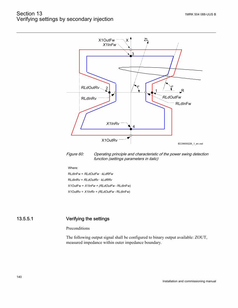
X1OutRv
ZL
j jR
XX1OutFwX1InFw
1RLdOutFw
RLdInFw
RLdOutRv
RLdInRv
2
3
4X1InRv
IEC09000226_1_en.vsdIEC09000226 V1 EN
Figure 60: Operating principle and characteristic of the power swing detectionfunction (settings parameters in italic)
Where:
RLdInFw = RLdOutFw · kLdRFw
RLdInRv = RLdOutRv · kLdRRv
X1OutFw = X1InFw + (RLdOutFw - RLdInFw)
X1OutRv = X1InRv + (RLdOutFw - RLdInFw)
13.5.5.1 Verifying the settings
Preconditions
The following output signal shall be configured to binary output available: ZOUT,measured impedance within outer impedance boundary.
Section 13 1MRK 504 088-UUS BVerifying settings by secondary injection
140Installation and commissioning manual
1. Keep the measured current as close as possible to its rated value or lower. Keep itconstant during the test, but ensure that it is higher than 30% of the rated current.
2. Ensure that the maximum continuous current of the IED does not exceed fourtimes its rated value, if the measurement of the operating characteristics runsunder constant voltage conditions.
3. Make the necessary connections and settings of the test equipment for test ofpoint 1 according to figure 60.
4. Decrease the measured impedance slowly and observe the operation value for thesignal ZOUT.
5. Check the operation value with the setting table.6. Do the necessary change of the setting of the test equipment and repeat step 4 and
step 5 for point 2, 3 and 4 according to figure 60.
13.5.5.2 Testing the power swing detection function ZMRPSB (78)
Preconditions
The following output signal shall be configured to a binary output: ZOUT, measuredimpedance within outer impedance boundary, ZIN, measured impedance within innerimpedance boundary and PICKUP, power swing detection.
1. Slowly decrease the measured impedance in all three phases until the PICKUPsignal gets activated.
2. Increase the measured voltages to their rated values.3. Decrease instantaneously voltages in all three phases to the values, which are
approximately 20% lower than the voltage that gives the set value R1LIn at thepredefined test current.
4. The PICKUP signal must not appear.5. Increase the measured voltages to their rated values.
13.5.5.3 Testing the tR1 timer
Preconditions
• The input I0CHECK, residual current (3I0) detection used to inhibit start output isconfigured to the output signal STPE on the phase selection with loadencroachment, quadrilateral characteristic function FDPSPDIS (21) or FRPSPDIS(21).
• The input BLK_SS, block inhibit of start output for subsequent residual currentdetection is connected to FALSE.
1MRK 504 088-UUS B Section 13Verifying settings by secondary injection
141Installation and commissioning manual
1. Program the test equipment for a single phase-to-ground fault and energizeFDPSPDIS (21) or FRPSDIS (21) and check that the input BLOCK on the powerswing detection function ZMRPSB (78) is activated.
2. Make a test sequence so that a single phase-to-ground fault occurs after that thetrajectory of the impedance has passed the outer and inner boundary of ZMRPSB(78) during power swing. Use the result from test of ZMRPSB (78) above todetermine when the fault shall be applied. The ground-fault must be activatedbefore tR1 has elapsed.
3. Start the sequence and observe that the PICKUP signal will not be activated.
13.5.5.4 Testing the block input, interaction between FDPSPDIS (21) orFRPSPDIS (21) and ZMRPSB (78)
Precondition
The BLOCK input is configured and connected to STPE output on the FDPSPDIS (21)or FRPSPDIS (21) function.
1. Make a test sequence so that a single phase-to-ground-fault occurs after that thetrajectory of the impedance has passed the outer boundary but not the innerboundary of the power swing detection function ZMRPSB (78). Use the resultfrom test of ZMRPSB (78) above to instance when the fault shall be applied.
2. Start the test sequence by continuously reducing the voltage and observe that theoutput signal ZOUT may come, but not PICKUP.If the input I0CHECK is configured (connected to output signal STPE onFDPSPDIS (21) or FRPSPDIS (21)), the test of inhibit of ZMRPSB (78) atground-fault during power swing can be done in the same way as for test of tR1.The inhibit of ZMRPSB (78) shall be instantaneous if the input TRSP is activatedat the same time as the input I0CHECK during power swing.
13.5.5.5 Completing the test
Continue to test another function or end the test by changing the Test mode setting toOff. Restore connections and settings to their original values, if they were changed fortesting purposes.
13.5.6 Power swing logic ZMRPSLPrepare the IED for verification of settings as outlined in section "Overview" andsection "Preparing for test" in this chapter.
Most readily available test equipment does not permit simulation of power-swingconditions and the simultaneous occurrence of different faults with controlled fault
Section 13 1MRK 504 088-UUS BVerifying settings by secondary injection
142Installation and commissioning manual
impedance. For this reason it is necessary to enable the logic by connecting the STPSDinput signal to some other functional signal, which is used for testing purposes.
Make sure that the existing configuration permits monitoring of the CS, TRIP signalson the binary outputs of the IED. If not, configure connections to unused binaryoutputs, for test purposes.
13.5.6.1 Testing the carrier send and trip signals
Procedure
1. Set the operation of all distance zones, which are supposed to be blocked by theoperation of ZMRPSB (78), to Off.
2. Configure the PUPSD functional inputs to the TRIP output of the underreachingpower-swing zone, if the underreaching communication scheme is used.
3. Start instantaneously any kind of fault within the underreaching power-swingzone and check, that:• The CS signal appears after the time delay, which is equal to the sum of set
time delays for the underreaching zone tnPP or tnPG (dependent on thetype of fault) and for the carrier send security timer tCS. Also add the usualoperate time for the underreaching zone (approximately 30ms).
• The TRIP signal appears after the time delay, which is equal to the sum ofset time delays for the underreaching zone tnPP or tnPG (dependent on thetype of fault) and for the trip security timer tTrip. Also add the usualoperate time for the underreaching zone (approximately 30ms).
4. Simulate the receiving of the carrier signal so that the functional input signal CRbecomes a logical one.
5. Configure the PUPSD input to connect to the output START of the carrieraccelerating zone (Power-swing overreaching zone).
6. Initiate any kind of fault within the carrier accelerating zone and check that theTRIP signal appears after the time, which is equal to the time delay set on the triptimer tTrip.Also consider the (average) operate time of the carrier acceleration zone(approximately 30ms).
13.5.6.2 Testing the influence of the residual overcurrent protection
Additionally connect the IED according to the test instructions for the four stepresidual overcurrent protection function EF4PTOC (51N/67N), if the Power swinglogic (ZMRPSL) is configured in a way that is controlled by this protection.
Procedure
1MRK 504 088-UUS B Section 13Verifying settings by secondary injection
143Installation and commissioning manual
1. Initiate a single phase-to-ground fault within both power-swing zones.Make sure that none of CS and TRIP output signals appear after the time delaystCS and tTrip.BLKZMUR must appear together with the fault and must remain active until thefault has been switched off plus the time delay, as set on the tBlkTr timer.
2. Initiate a phase-to-phase fault within the operating area of both power-swing zones.Make sure that CS and TRIP output signals appear after the time delays tCS.
3. Switch the operation of the zone 1 distance protection function on and fulfill allthe conditions for single-pole autoreclosing.
4. Simulate a single phase-to-ground fault within the reach of zone 1 and both power-swing zones.The fault should cause a single-pole tripping and should be switched off with thenormal operating time of zone 1.
5. Repeat the fault within the dead time of single-pole autoreclosing.Make sure, that ZMRPSL generates a BLKZMUR signal and no CS and TRIP.
13.5.6.3 Controlling of the underreaching zone
Procedure
1. Set the operation of all normal distance protection zones to On.2. Simulate a fault without fault resistance in the middle of distance protection zone
1.Make sure that the trip appears within the operate time for the distance protectionzone 1 and no BLKZMOR output signal appears.
3. Switch off the fault and prepare a new fault without fault resistance within thenormal distance protection zone 2 operate area, but outside the zone 1 operate area.
4. Switch on the fault and move it into the zone 1 operate area with a time delaylonger than the time set on the tDZ timer and faster than the time set on timer tZL.
5. Observe the operate time, which must be equal to the operate time of zone 1, afterthe measured impedance enters its operate area.No delayed operation of zone 1 must be observed.
6. Configure the PUPSD functional input to connect to the START functionaloutput and repeat the previous fault.Fast trip, caused by the operation of zone 1 must appear with a time delay, whichis equal to the set time delay on the timer tZL plus zone 1 normal operate time.Also, observe the BLKZMOR functional output signal, which must appear for ashort time.
7. Be sure to establish the original configuration of the IED and the original settingsof all setting parameters.
Section 13 1MRK 504 088-UUS BVerifying settings by secondary injection
144Installation and commissioning manual
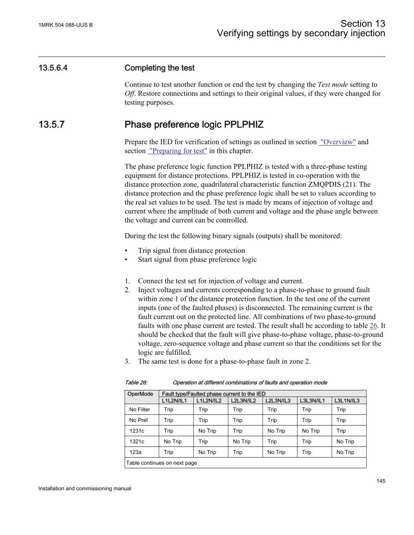
13.5.6.4 Completing the test
Continue to test another function or end the test by changing the Test mode setting toOff. Restore connections and settings to their original values, if they were changed fortesting purposes.
13.5.7 Phase preference logic PPLPHIZPrepare the IED for verification of settings as outlined in section "Overview" andsection "Preparing for test" in this chapter.
The phase preference logic function PPLPHIZ is tested with a three-phase testingequipment for distance protections. PPLPHIZ is tested in co-operation with thedistance protection zone, quadrilateral characteristic function ZMQPDIS (21). Thedistance protection and the phase preference logic shall be set to values according tothe real set values to be used. The test is made by means of injection of voltage andcurrent where the amplitude of both current and voltage and the phase angle betweenthe voltage and current can be controlled.
During the test the following binary signals (outputs) shall be monitored:
• Trip signal from distance protection• Start signal from phase preference logic
1. Connect the test set for injection of voltage and current.2. Inject voltages and currents corresponding to a phase-to-phase to ground fault
within zone 1 of the distance protection function. In the test one of the currentinputs (one of the faulted phases) is disconnected. The remaining current is thefault current out on the protected line. All combinations of two phase-to-groundfaults with one phase current are tested. The result shall be according to table 26. Itshould be checked that the fault will give phase-to-phase voltage, phase-to-groundvoltage, zero-sequence voltage and phase current so that the conditions set for thelogic are fulfilled.
3. The same test is done for a phase-to-phase fault in zone 2.
Table 26: Operation at different combinations of faults and operation mode
OperMode Fault type/Faulted phase current to the IEDL1L2N/IL1 L1L2N/IL2 L2L3N/IL2 L2L3N/IL3 L3L3N/IL1 L3L1N/IL3
No Filter Trip Trip Trip Trip Trip Trip
No Pref Trip Trip Trip Trip Trip Trip
1231c Trip No Trip Trip No Trip No Trip Trip
1321c No Trip Trip No Trip Trip Trip No Trip
123a Trip No Trip Trip No Trip Trip No Trip
Table continues on next page
1MRK 504 088-UUS B Section 13Verifying settings by secondary injection
145Installation and commissioning manual
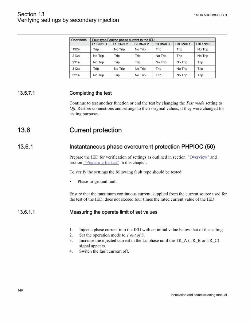
OperMode Fault type/Faulted phase current to the IEDL1L2N/IL1 L1L2N/IL2 L2L3N/IL2 L2L3N/IL3 L3L3N/IL1 L3L1N/IL3
132a Trip No Trip No Trip Trip Trip No Trip
213a No Trip Trip Trip No Trip Trip No Trip
231a No Trip Trip Trip No Trip No Trip Trip
312a Trip No Trip No Trip Trip No Trip Trip
321a No Trip Trip No Trip Trip No Trip Trip
13.5.7.1 Completing the test
Continue to test another function or end the test by changing the Test mode setting toOff. Restore connections and settings to their original values, if they were changed fortesting purposes.
13.6 Current protection
13.6.1 Instantaneous phase overcurrent protection PHPIOC (50)Prepare the IED for verification of settings as outlined in section "Overview" andsection "Preparing for test" in this chapter.
To verify the settings the following fault type should be tested:
• Phase-to-ground fault
Ensure that the maximum continuous current, supplied from the current source used forthe test of the IED, does not exceed four times the rated current value of the IED.
13.6.1.1 Measuring the operate limit of set values
1. Inject a phase current into the IED with an initial value below that of the setting.2. Set the operation mode to 1 out of 3.3. Increase the injected current in the Ln phase until the TR_A (TR_B or TR_C)
signal appears.4. Switch the fault current off.
Section 13 1MRK 504 088-UUS BVerifying settings by secondary injection
146Installation and commissioning manual
Observe: Do not exceed the maximum permitted overloading ofthe current circuits in the IED.
5. Compare the measured operating current with the set value.6. Set the operation mode to 2 out of 3 and inject current into one of the phases.
Check - no operation.
13.6.1.2 Completing the test
Continue to test another function or end the test by changing the Test mode setting toOff. Restore connections and settings to their original values, if they were changed fortesting purposes.
13.6.2 Four step phase overcurrent protection OC4PTOC (51/67)Prepare the IED for verification of settings outlined in section "Overview" and section "Preparing for test" in this chapter.
13.6.2.1 Verifying the settings
1. Connect the test set for appropriate current injection to the appropriate IED phases.If there is any configuration logic that is used to enable or block any of the fouravailable overcurrent steps, make sure that the step under test is enabled, forexample end fault protection.If 1 out of 3 currents for operation is chosen: Connect the injection current tophases A and neutral.If 2 out of 3 currents for operation is chosen: Connect the injection current intophase A and out from phase B.If 3 out of 3 currents for operation is chosen: Connect the symmetrical three-phase injection current into phases A, B and C.
2. Connect the test set for the appropriate three-phase voltage injection to the IEDphases A, B and C. The protection shall be fed with a symmetrical three-phasevoltage.
3. Set the injected polarizing voltage slightly larger than the set minimum polarizingvoltage (default is 5% of VBase) and set the injection current to lag theappropriate voltage by an angle of about 80° if forward directional function isselected.If 1 out of 3 currents for operation is chosen: The voltage angle of phase A is thereference.If 2 out of 3 currents for operation is chosen: The voltage angle of phase A – thevoltage angle of B is the reference.
1MRK 504 088-UUS B Section 13Verifying settings by secondary injection
147Installation and commissioning manual
If 3 out of 3 currents for operation is chosen: The voltage angle of phase A is thereference.If reverse directional function is selected, set the injection current to lag thepolarizing voltage by an angle equal to 260° (equal to 80° + 180°).
4. Increase the injected current and note the operated value of the tested step of thefunction.
5. Decrease the current slowly and note the reset value.6. If the test has been performed by injection of current in phase A, repeat the test
when injecting current into phases B and C with polarizing voltage connected tophases B respectively C (1 out of 3 currents for operation).
7. If the test has been performed by injection of current in phases A — B, repeat thetest when injecting current into phases B — C and C — A with appropriate phaseangle of injected currents.
8. Block higher set stages when testing lower set stages according to below.9. Connect a trip output contact to a timer.10. Set the injected current to 200% of the operate level of the tested stage, switch on
the current and check the time delay.For inverse time curves, check the operate time at a current equal to 110% of theoperate current for txMin.
11. Check that all trip and pickup contacts operate according to the configuration(signal matrixes)
12. Reverse the direction of the injected current and check that the protection doesnot operate.
13. If 2 out of 3 or 3 out of 3 currents for operation is chosen: Check that the functionwill not operate with current in one phase only.
14. Repeat the above described tests for the higher set stages.15. Finally check that pickup and trip information is stored in the event menu.
Check of the non-directional phase overcurrent function. This isdone in principle as instructed above, without applying anypolarizing voltage.
13.6.2.2 Completing the test
Continue to test another function or end the test by changing the Test mode setting toOff. Restore connections and settings to their original values, if they were changed fortesting purposes.
13.6.3 Instantaneous residual overcurrent protection EFPIOC (50N)Prepare the IED for verification of settings as outlined in section "Overview" andsection "Preparing for test" in this chapter.
Section 13 1MRK 504 088-UUS BVerifying settings by secondary injection
148Installation and commissioning manual
To verify the settings the following fault type should be tested:
• Phase-to-ground fault
Ensure that the maximum continuous current, supplied from the current source used forthe test of the IED, does not exceed four times the rated current value of the IED.
13.6.3.1 Measuring the operate limit of set values
1. Inject a phase current into the IED with an initial value below that of the setting.2. Increase the injected current in the Ln or in the neutral (summated current input)
phase until the TRIP signal appears.3. Switch the fault current off.
Observe to not exceed the maximum permitted overloading of the current circuitsin the IED
4. Compare the measured operating current with the set value.
13.6.3.2 Completing the test
Continue to test another function or end the test by changing the Test mode setting toOff. Restore connections and settings to their original values, if they were changed fortesting purposes.
13.6.4 Four step residual overcurrent protection EF4PTOC (51N/67N)Prepare the IED for verification of settings as outlined in section "Overview" andsection "Preparing for test" in this chapter.
13.6.4.1 Four step directional overcurrent protection
1. Connect the test set for single current injection to the appropriate IED terminals.Connect the injection current to terminals A and neutral, or to terminals N andneutral.
2. Set the injected polarizing voltage slightly larger than the set minimum polarizingvoltage (default 5% of Vn) and set the injection current to lag the voltage by anangle equal to the set reference characteristic angle (AngleRCA) if the forwarddirectional function is selected.
1MRK 504 088-UUS B Section 13Verifying settings by secondary injection
149Installation and commissioning manual
If reverse directional function is selected, set the injection current to lag thepolarizing voltage by an angle equal to RCA+ 180°.
3. Increase the injected current and note the value at which the studied step of thefunction operates.
4. Decrease the current slowly and note the reset value.5. If the test has been performed by injection of current in phase A, repeat the test
when injecting current into terminals B and C with a polarizing voltage connectedto terminals B respectively C.
6. Block lower set steps when testing higher set steps according to the instructionsthat follow.
7. Connect a trip output contact to a timer.8. Set the injected current to 200% of the operate level of the tested step, switch on
the current and check the time delay.For inverse time curves, check the operate time at a current equal to 110% of theoperate current for txMin.
9. Check that all trip and start contacts operate according to the configuration(signal matrixes)
10. Reverse the direction of the injected current and check that the step does not operate.11. Check that the protection does not operate when the polarizing voltage is zero.12. Repeat the above described tests for the higher set steps.13. Finally, check that pickup and trip information is stored in the event menu.
13.6.4.2 Four step non-directional overcurrent protection
1. Do as described in "Four step directional overcurrent protection", but withoutapplying any polarizing voltage.
13.6.4.3 Completing the test
Continue to test another function or end the test by changing the Test mode setting toOff. Restore connections and settings to their original values, if they were changed fortesting purposes.
13.6.5 Sensitive directional residual overcurrent and powerprotection SDEPSDE (67N)Prepare the IED for verification of settings as outlined in section "Overview" andsection "Preparing for test" in this chapter
Figure 61 shows the principal connection of the test set during the test of the sensitivedirectional residual overcurrent protection. Observe that the polarizing voltage is equalto -3V0.
Section 13 1MRK 504 088-UUS BVerifying settings by secondary injection
150Installation and commissioning manual
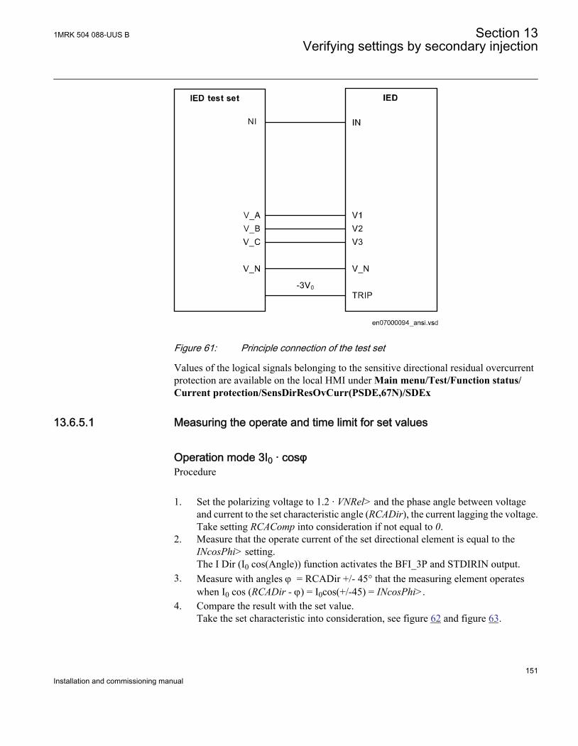
ANSI07000094 V2 EN
Figure 61: Principle connection of the test set
Values of the logical signals belonging to the sensitive directional residual overcurrentprotection are available on the local HMI under Main menu/Test/Function status/Current protection/SensDirResOvCurr(PSDE,67N)/SDEx
13.6.5.1 Measuring the operate and time limit for set values
Operation mode 3I0 · cosφProcedure
1. Set the polarizing voltage to 1.2 · VNRel> and the phase angle between voltageand current to the set characteristic angle (RCADir), the current lagging the voltage.Take setting RCAComp into consideration if not equal to 0.
2. Measure that the operate current of the set directional element is equal to theINcosPhi> setting.The I Dir (I0 cos(Angle)) function activates the BFI_3P and STDIRIN output.
3. Measure with angles j = RCADir +/- 45° that the measuring element operateswhen I0 cos (RCADir - j) = I0cos(+/-45) = INcosPhi>.
4. Compare the result with the set value.Take the set characteristic into consideration, see figure 62 and figure 63.
1MRK 504 088-UUS B Section 13Verifying settings by secondary injection
151Installation and commissioning manual
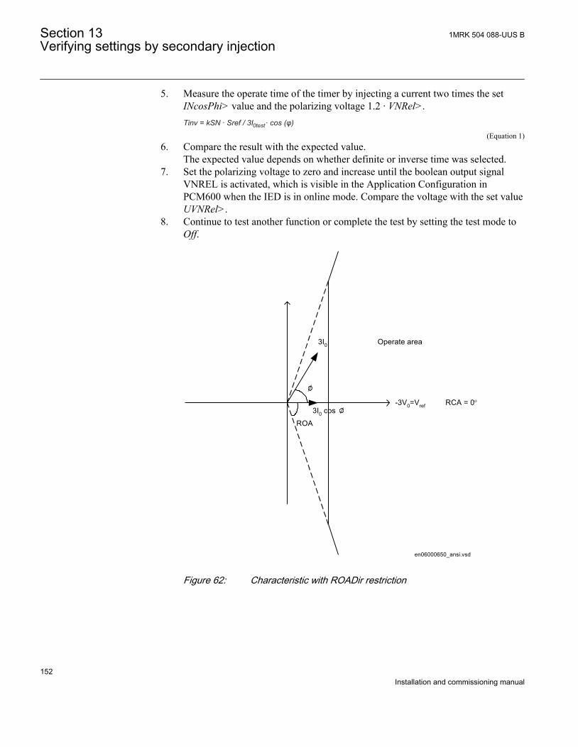
5. Measure the operate time of the timer by injecting a current two times the setINcosPhi> value and the polarizing voltage 1.2 · VNRel>.Tinv = kSN · Sref / 3I · cos (φ)0test
EQUATION2228 V1 EN (Equation 1)6. Compare the result with the expected value.
The expected value depends on whether definite or inverse time was selected.7. Set the polarizing voltage to zero and increase until the boolean output signal
VNREL is activated, which is visible in the Application Configuration inPCM600 when the IED is in online mode. Compare the voltage with the set valueUVNRel>.
8. Continue to test another function or complete the test by setting the test mode toOff.
-3V0=Vref
3I0
RCA = 0°3I0 cos
Operate area
ROA
en06000650_ansi.vsdANSI06000650 V1 EN
Figure 62: Characteristic with ROADir restriction
Section 13 1MRK 504 088-UUS BVerifying settings by secondary injection
152Installation and commissioning manual
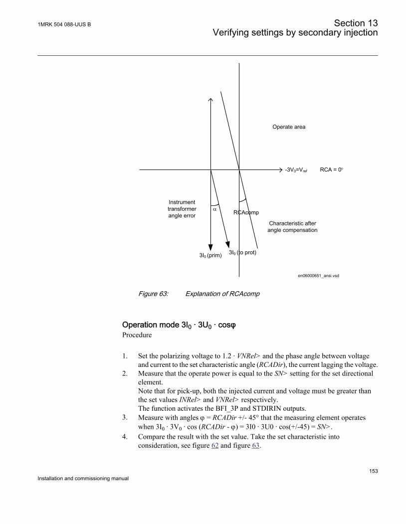
-3V0=Vref RCA = 0°
Operate area
Instrument transformer angle error
3I0 (prim) 3I0 (to prot)
a
Characteristic after angle compensation
RCAcomp
en06000651_ansi.vsdANSI06000651 V1 EN
Figure 63: Explanation of RCAcomp
Operation mode 3I0 · 3U0 · cosφProcedure
1. Set the polarizing voltage to 1.2 · VNRel> and the phase angle between voltageand current to the set characteristic angle (RCADir), the current lagging the voltage.
2. Measure that the operate power is equal to the SN> setting for the set directionalelement.Note that for pick-up, both the injected current and voltage must be greater thanthe set values INRel> and VNRel> respectively.The function activates the BFI_3P and STDIRIN outputs.
3. Measure with angles j = RCADir +/- 45° that the measuring element operateswhen 3I0 · 3V0 · cos (RCADir - j) = 3I0 · 3U0 · cos(+/-45) = SN>.
4. Compare the result with the set value. Take the set characteristic intoconsideration, see figure 62 and figure 63.
1MRK 504 088-UUS B Section 13Verifying settings by secondary injection
153Installation and commissioning manual
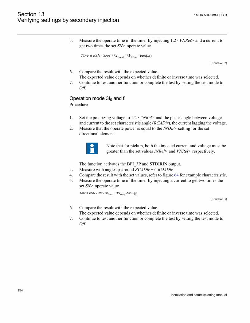
5. Measure the operate time of the timer by injecting 1.2 · VNRel> and a current toget two times the set SN> operate value.
0 0/ 3 3 cos( )test testTinv kSN Sref I V j= × × ×
EQUATION2066-ANSI V1 EN (Equation 2)
6. Compare the result with the expected value.The expected value depends on whether definite or inverse time was selected.
7. Continue to test another function or complete the test by setting the test mode toOff.
Operation mode 3I0 and fiProcedure
1. Set the polarizing voltage to 1.2 · VNRel> and the phase angle between voltageand current to the set characteristic angle (RCADir), the current lagging the voltage.
2. Measure that the operate power is equal to the INDir> setting for the setdirectional element.
Note that for pickup, both the injected current and voltage must begreater than the set values INRel> and VNRel> respectively.
The function activates the BFI_3P and STDIRIN output.3. Measure with angles j around RCADir +/- ROADir.4. Compare the result with the set values, refer to figure 64 for example characteristic.5. Measure the operate time of the timer by injecting a current to get two times the
set SN> operate value.Tinv = kSN Sref / 3I · 3U cos (φ)0test 0test
EQUATION2229 V1 EN (Equation 3)
6. Compare the result with the expected value.The expected value depends on whether definite or inverse time was selected.
7. Continue to test another function or complete the test by setting the test mode toOff.
Section 13 1MRK 504 088-UUS BVerifying settings by secondary injection
154Installation and commissioning manual
-3V0
RCA = 0°
8080
ROA = 80°
Operate area
3I0
en06000652_ansi.vsdANSI06000652 V1 EN
Figure 64: Example characteristic
Non-directional ground fault current protectionProcedure
1. Measure that the operate current is equal to the INNonDir> setting.The function activates the BFI_3P and STDIRIN output.
2. Measure the operate time of the timer by injecting a current to get two times theset INNonDir> operate value.
3. Compare the result with the expected value.The expected value depends on whether definite time tINNonDir or inverse timewas selected.
4. Continue to test another function or complete the test by setting the test mode toOff.
Residual overvoltage release and protectionProcedure
1. Measure that the operate voltage is equal to the UN> setting.The function activates the BFI_3P and STUN signals.
2. Measure the operate time by injecting a voltage 1.2 timers set VN> operate value.3. Compare the result with the set tVNNonDir operate value.
1MRK 504 088-UUS B Section 13Verifying settings by secondary injection
155Installation and commissioning manual
4. Inject a voltage 0.8 · VNRel> and a current high enough to operate the directionalfunction at the chosen angle.
5. Increase the voltage until the directional function is released.6. Compare the measured value with the set VNRel> operate value.
13.6.5.2 Completing the test
Continue to test another function or end the test by changing the Test mode setting toOff. Restore connections and settings to their original values, if they were changed fortesting purposes.
13.6.6 Thermal overload protection, two time constants TRPTTR (49)Prepare the IED for verification of settings as outlined in section "Overview" andsection "Preparing for test" in this chapter.
13.6.6.1 Checking operate and reset values
Procedure
1. Connect symmetrical three-phase currents to the appropriate current terminals ofthe IED.
2. Set the Time constant 1 (Tau1) and Time Constant 2 (Tau2) temporarily to 1 minute.3. Set the three-phase injection currents slightly lower than the set operate value of
stage IBase1, increase the current in phase A until stage IBase1 operates and notethe operate value.
Observe the maximum permitted overloading of the currentcircuits in the IED.
4. Decrease the current slowly and note the reset value.
Check in the same way as the operate and reset values of IBase1 for phases B andC.
5. Activate the digital input for cooling input signal to switch over to base currentIBase2.
6. Check for all three phases the operate and reset values for IBase2in the same wayas described above for stage IBase1
7. Deactivate the digital input signal for stage IBase2.8. Set the time constant for IBase1 in accordance with the setting plan.9. Set the injection current for phase A to 1.50 · IBase1.10. Connect a trip output contact to the timer and monitor the output of contacts
ALARM1 and ALARM2 to digital inputs in test equipment.
Section 13 1MRK 504 088-UUS BVerifying settings by secondary injection
156Installation and commissioning manual
Read the heat content in the thermal protection from the local HMI and wait untilthe content is zero.
11. Switch on the injection current and check that ALARM1 and ALARM2 contactsoperate at the set percentage level and that the operate time for tripping is inaccordance with the set Time Constant 1 (Tau1).With setting Itr = 101%IBase1 and injection current 1.50 · IBase1, the trip timefrom zero content in the memory shall be 0.60 · Time Constant 1 (Tau1).
12. Check that all trip and alarm contacts operate according to the configuration logic.13. Switch off the injection current and check from the service menu readings of
thermal status and LOCKOUT that the lockout resets at the set percentage of heatcontent.
14. Activate the digital input for cooling input signal to switch over to base currentIBase2.Wait 5 minutes to empty the thermal memory and set Time Constant 2 (Tau2) inaccordance with the setting plan.
15. Test with injection current 1.50 · IBase2 the thermal alarm level, the operate timefor tripping and the lockout reset in the same way as described for stage IBase1.
16. Finally check that pickup and trip information is stored in the event menu.
13.6.6.2 Completing the test
Continue to test another function or end the test by changing the Test mode setting toOff. Restore connections and settings to their original values, if they were changed fortesting purposes.
13.6.7 Breaker failure protection CCRBRF (50BF)Prepare the IED for verification of settings as outlined in section "Overview" andsection "Preparing for test" in this chapter.
The breaker failure protection function CCRBRF (50BF) should normally be tested inconjunction with some other function that provides an initiate signal. An externalINITIATE signal can also be used.
To verify the settings in the most common back-up trip mode 1 out of 3, it is sufficientto test phase-to-ground faults.
At mode 2 out of 4 the phase current setting, Pickup_PH can be checked by single-phase injection where the return current is connected to the summated current input.The value of residual (earth fault) current IN set lower than Pickup_PH is easiestchecked in back-up trip mode 1 out of 4.
1MRK 504 088-UUS B Section 13Verifying settings by secondary injection
157Installation and commissioning manual
13.6.7.1 Checking the phase current operate value, Pickup_PH
The check of the Pickup_PH current level is best made in FunctionMode = Currentand BuTripMode = 1 out of 3 or 2 out of 4.
1. Apply the fault condition, including INITIATION of CCRBRF (50BF), with acurrent below set Pickup_PH.
2. Repeat the fault condition and increase the current in steps until a trip occurs.3. Compare the result with the set Pickup_PH.4. Disconnect AC and INITIATE input signals.
Note! If NoIPickupcheck or Retrip off is set, only back-up trip canbe used to check set Pickup_PH.
13.6.7.2 Checking the residual (ground fault) current operate value Pickup_N setbelow Pickup_PH
Check the low set Pickup_N current where setting FunctionMode = Current and settingBuTripMode = 1 out of 4
1. Apply the fault condition, including INITIATION of CCRBRF (50BF), with acurrent just below set IN>Pickup_N.
2. Repeat the fault condition and increase the current in steps until trip appears.3. Compare the result with the set Pickup_N.4. Disconnect AC and INITIATION input signals.
13.6.7.3 Checking the re-trip and back-up times
The check of the set times can be made in connection with the check of operate valuesabove.
Choose the applicable function and trip mode, such as FunctionMode = Current andRetripMode = Current check.
1. Apply the fault condition, including initiation of CCRBRF (50BF), well abovethe set current value. Measure time from INITIATION of CCRBRF (50BF).
2. Check the re-trip t1 and back-up trip times t2 and t3.In applicable cases, the back-up trip for multi-phase start t2MPh and back-up trip2, t2 and t3 can also be checked. To check t2MPh, a two-phase or three-phaseinitiation shall be applied.
3. Disconnect AC and INITIATE input signals.
Section 13 1MRK 504 088-UUS BVerifying settings by secondary injection
158Installation and commissioning manual
13.6.7.4 Verifying the re-trip mode
Choose the mode below, which corresponds to the actual case.
In the cases below it is assumed that FunctionMode = Current is selected.
Checking the case without re-trip, RetripMode = Retrip Off
1. Set RetripMode = Retrip Off.2. Apply the fault condition, including initiation of CCRBRF (50BF), well above
the set current value.3. Verify that no re-trip, but back-up trip is achieved after set time.4. Disconnect AC and INITIATE input signals.
Checking the re-trip with current check, RetripMode = CB Pos Check
1. Set RetripMode = CB Pos Check.2. Apply the fault condition, including initiation of CCRBRF (50BF), well above
the set current value.3. Verify that re-trip is achieved after set time t1 and back-up trip after time t24. Apply the fault condition, including initiation of CCRBRF (50BF), with current
below set current value.5. Verify that no re-trip, and no back-up trip is obtained.6. Disconnect AC and INITIATE input signals.
Checking re-trip without current check, RetripMode = No CBPos Check
1. Set RetripMode = No CBPos Check.2. Apply the fault condition, including initiation of CCRBRF (50BF), well above
the set current value.3. Verify that re-trip is achieved after set time t1, and back-up trip after time t2.4. Apply the fault condition, including initiation of CCRBRF (50BF), with current
below set current value.5. Verify that re-trip is achieved after set time t1, but no back-up trip is obtained.6. Disconnect AC and INITIATE input signals.
13.6.7.5 Verifying the back-up trip mode
In the cases below it is assumed that FunctionMode = Current is selected.
Checking that back-up tripping is not achieved at normal CB trippingUse the actual tripping modes. The case below applies to re-trip with current check.
1MRK 504 088-UUS B Section 13Verifying settings by secondary injection
159Installation and commissioning manual
1. Apply the fault condition, including initiation of CCRBRF (50BF), with phasecurrent well above set value IP.
2. Arrange switching the current off, with a margin before back-up trip time, t2. Itmay be made at issue of re-trip command.
3. Check that re-trip is achieved, if selected, but no back-up trip.4. Disconnect AC and INITIATE input signals.
The normal mode BuTripMode = 1 out of 3 should have been verified in the testsabove. In applicable cases the modes 1 out of 4 and 2 out of 4 can be checked. Choosethe mode below, which corresponds to the actual case.
Checking the case BuTripMode = 1 out of 4It is assumed that the earth-fault current setting Pickup_N is below phase currentsetting Pickup_PH.
1. Set BuTripMode = 1 out of 4.2. Apply the fault condition, including initiation of CCRBRF (50BF), with one-
phase current below set Pickup_PH but above Pickup_N. The residual earth faultshould then be above set Pickup_N.
3. Verify that back-up trip is achieved after set time. If selected, re-trip should alsoappear.
4. Disconnect AC and INITIATE input signals.
Checking the case BuTripMode = 2 out of 4The earth-fault current setting Pickup_N may be equal to or below phase-currentsetting Pickup_PH.
1. Set BuTripMode = 2 out of 4.2. Apply the fault condition, including initiation of CCRBRF (50BF), with one-
phase current above set Pickup_PH and residual (ground fault) above setPickup_N. It can be obtained by applying a single-phase current.
3. Verify that back-up trip is achieved after set time. If selected, re-trip should alsoappear.
4. Apply the fault condition, including initiation of CCRBRF (50BF), with at leastone-phase current below set Pickup_PH and residual (ground fault) above setPickup_N. The current may be arranged by feeding three- (or two-) phasecurrents with equal phase angle (I0-component) below Pickup_PH, but of suchvalue that the residual (ground fault) current (3I0) will be above set valuePickup_N.
5. Verify that back-up trip is not achieved.6. Disconnect AC and INITIATE input signals.
Section 13 1MRK 504 088-UUS BVerifying settings by secondary injection
160Installation and commissioning manual
13.6.7.6 Verifying instantaneous back-up trip at CB faulty condition
Applies in a case where a signal from CB supervision function regarding CB beingfaulty and unable to trip is connected to input 52FAIL.
1. Repeat the check of back-up trip time. Disconnect current and INITIATE inputsignals.
2. Activate the input 52FAIL. The output CBALARM (CB faulty alarm) shouldappear after set time tCBAlarm. Keep the input activated.
3. Apply the fault condition, including initiation of CCRBRF (50BF), with currentabove set current value.
4. Verify that back-up trip is obtained without intentional delay, for example within20ms from application of initiation.
5. Disconnect injected AC and INITIATEinput signals.
13.6.7.7 Verifying the case RetripMode = Contact
It is assumed that re-trip without current check is selected, RetripMode = Contact.
1. Set FunctionMode = Contact2. Apply input signal for CB closed to relevant input or inputs 52a_A (B or C)3. Apply input signal, or signals for initiation of CCRBRF (50BF). The value of
current could be low.4. Verify that re-trip and back-up trip are achieved after set times.5. Disconnect the start signal(s). Keep the CB closed signal(s).6. Apply input signal(s), for initiation of CCRBRF (50BF). The value of current
could be low.7. Arrange disconnection of CB closed signal(s) well before set back-up trip time t2.8. Verify that back-up trip is not achieved.9. Disconnect injected AC and INITIATE input signals.
13.6.7.8 Verifying the function mode Current&Contact
To be made only when FunctionMode = Current&Contact is selected. It is suggestedto make the tests in one phase only, or at three-pole trip applications for just three-poletripping.
Checking the case with fault current above set value Pickup_PHThe operation shall be as in FunctionMode = Current.
1MRK 504 088-UUS B Section 13Verifying settings by secondary injection
161Installation and commissioning manual
1. Set FunctionMode = Current&Contact.2. Leave the inputs for CB close inactivated. These signals should not influence.3. Apply the fault condition, including initiation of CCRBRF (50BF), with current
above the set Pickup_PH value.4. Check that the re-trip, if selected, and back-up trip commands are achieved.5. Disconnect injected AC and INITIATE input signals.
Checking the case with fault current below set value Pickup_BlkContThe case shall simulate a case where the fault current is very low and operation willdepend on CB position signal from CB auxiliary contact. It is suggested that re-tripwithout current check is used, setting RetripMode = No CBPos Check.
1. Set FunctionMode = Current&Contact.2. Apply input signal for CB closed to relevant input or inputs 52a_A (B or C)3. Apply the fault condition with input signal(s) for initiation of CCRBRF (50BF).
The value of current should be below the set value Pickup_BlkCont4. Verify that re-trip (if selected) and back-up trip are achieved after set times.
Failure to trip is simulated by keeping the signal(s) CB closed activated.5. Disconnect the AC and the INITIATE signal(s). Keep the CB closed signal(s).6. Apply the fault and the initiation again. The value of current should be below the
set value Pickup_BlkCont.7. Arrange disconnection of BC closed signal(s) well before set back-up trip time t2.
It simulates a correct CB tripping.8. Verify that back-up trip is not achieved. Re-trip can appear for example, due to
selection “Re-trip without current check”.9. Disconnect injected AC and INITIATE input signals.
13.6.7.9 Completing the test
Continue to test another function or end the test by changing the Test mode setting toOff. Restore connections and settings to their original values, if they were changed fortesting purposes.
13.6.8 Pole discrepancy CCRPLD (52PD)Prepare the IED for verification of settings as outlined in section "Preparing for test"and section "Preparing for test" in this chapter.
13.6.8.1 Verifying the settings
Section 13 1MRK 504 088-UUS BVerifying settings by secondary injection
162Installation and commissioning manual
1. External detection logic, Contact function selection = ContactSel setting equalsCCRPLD (52PD) signal from CB. Activate the EXTPDIND binary input, andmeasure the operating time of CCRPLD (52PD).Use the TRIP signal from the configured binary output to stop the timer.
2. Compare the measured time with the set value tTrip.3. Reset the EXTPDIND input.4. Activate the BLKDBYAR binary input.
This test should be performed together with Autorecloser SMBRREC (79).5. Activate the EXTPDIND binary input.
No TRIP signal should appear.6. Reset both BLKDBYAR and EXTPDIND binary inputs.7. Activate the BLOCK binary input.8. Activate EXTPDIND binary input.
NO TRIP signal should appear.9. Reset both BLOCK and EXTPDIND binary inputs.10. If Internal detection logic Contact function selection = ContactSel setting equals
Pole position from auxiliary contacts. Then set inputs 52b_A...52a_C in a statusthat activates the pole discordance logic and repeats step 2 to step 6.
11. Unsymmetrical current detection with CB monitoring: Set measured current inone phase to 110% of current release level. Activate CLOSECMD and measurethe operating time of the CCRPLD (52PD) protection.Use the TRIP signal from the configured binary out put stop the timer.
12. 12. Deactivate the CLOSECMD: Set measured current in one phase to 90% ofCurrent Release level. Activate CLOSECMD.NO TRIP signal should appear.
13. 13. Repeat step 14 and 15 using OPENCMD instead of CLOSECMD.Asymmetry current detection with CB monitoring: Set all three currents to 110%of Current Release level. Activate CLOSECMD.NO TRIP signal should appear due to symmetrical condition.
14. 14. Deactivate the CLOSECMD. Decrease one current with 120% of the currentunsymmetrical level compared to the other two phases. Activate CLOSECMDand measure the operating time of the CCRPLD (52PD) protection.Use the TRIP signal from the configured binary out put stop the timer.
15. 15. Deactivate the CLOSECMD. Decrease one current with 80% of the currentunsymmetrical level compared to the other two phases. Activate CLOSECMD.NO TRIP signal should appear.
13.6.8.2 Completing the test
Continue to test another function or end the test by changing the Test mode setting toOff. Restore connections and settings to their original values, if they were changed fortesting purposes.
1MRK 504 088-UUS B Section 13Verifying settings by secondary injection
163Installation and commissioning manual
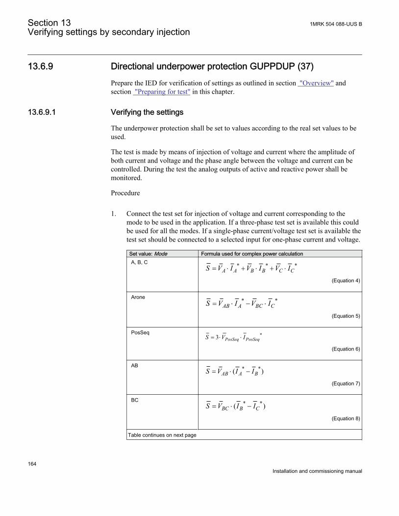
13.6.9 Directional underpower protection GUPPDUP (37)Prepare the IED for verification of settings as outlined in section "Overview" andsection "Preparing for test" in this chapter.
13.6.9.1 Verifying the settings
The underpower protection shall be set to values according to the real set values to beused.
The test is made by means of injection of voltage and current where the amplitude ofboth current and voltage and the phase angle between the voltage and current can becontrolled. During the test the analog outputs of active and reactive power shall bemonitored.
Procedure
1. Connect the test set for injection of voltage and current corresponding to themode to be used in the application. If a three-phase test set is available this couldbe used for all the modes. If a single-phase current/voltage test set is available thetest set should be connected to a selected input for one-phase current and voltage.
Set value: Mode Formula used for complex power calculationA, B, C * * *
A A B B C CS V I V I V I= × + × + ×
EQUATION2055 V1 EN (Equation 4)
Arone * *AB A BC CS V I V I= × - ×
EQUATION2056-ANSI V1 EN (Equation 5)
PosSeq *3 PosSeq PosSeqS V I= × ×
EQUATION2057-ANSI V1 EN (Equation 6)
AB * *( )AB A BS V I I= × -
EQUATION2058-ANSI V1 EN (Equation 7)
BC * *( )BC B CS V I I= × -
EQUATION2059-ANSI V1 EN (Equation 8)
Table continues on next page
Section 13 1MRK 504 088-UUS BVerifying settings by secondary injection
164Installation and commissioning manual
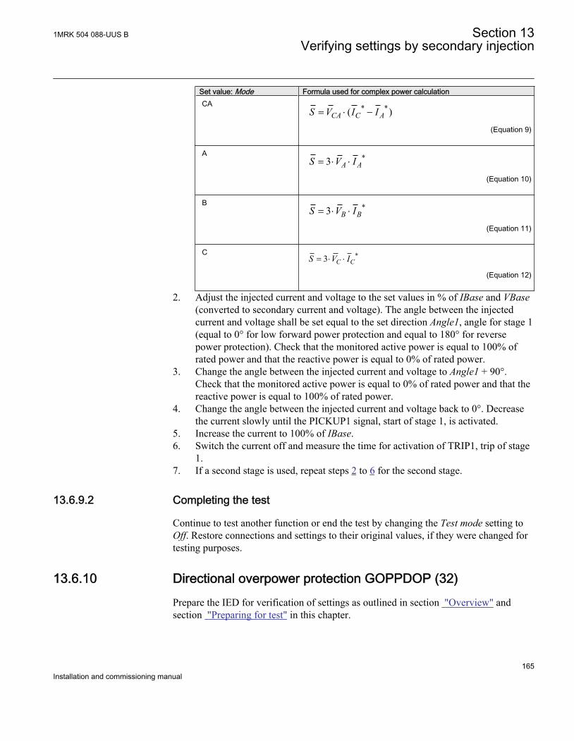
Set value: Mode Formula used for complex power calculationCA * *( )CA C AS V I I= × -
EQUATION2060-ANSI V1 EN (Equation 9)
A *3 A AS V I= × ×
EQUATION2061-ANSI V1 EN (Equation 10)
B *3 B BS V I= × ×
EQUATION2062-ANSI V1 EN (Equation 11)
C *3 C CS V I= × ×
EQUATION2063-ANSI V1 EN (Equation 12)
2. Adjust the injected current and voltage to the set values in % of IBase and VBase(converted to secondary current and voltage). The angle between the injectedcurrent and voltage shall be set equal to the set direction Angle1, angle for stage 1(equal to 0° for low forward power protection and equal to 180° for reversepower protection). Check that the monitored active power is equal to 100% ofrated power and that the reactive power is equal to 0% of rated power.
3. Change the angle between the injected current and voltage to Angle1 + 90°.Check that the monitored active power is equal to 0% of rated power and that thereactive power is equal to 100% of rated power.
4. Change the angle between the injected current and voltage back to 0°. Decreasethe current slowly until the PICKUP1 signal, start of stage 1, is activated.
5. Increase the current to 100% of IBase.6. Switch the current off and measure the time for activation of TRIP1, trip of stage
1.7. If a second stage is used, repeat steps 2 to 6 for the second stage.
13.6.9.2 Completing the test
Continue to test another function or end the test by changing the Test mode setting toOff. Restore connections and settings to their original values, if they were changed fortesting purposes.
13.6.10 Directional overpower protection GOPPDOP (32)Prepare the IED for verification of settings as outlined in section "Overview" andsection "Preparing for test" in this chapter.
1MRK 504 088-UUS B Section 13Verifying settings by secondary injection
165Installation and commissioning manual
13.6.10.1 Verifying the settings
The overpower protection shall be set to values according to the real set values to beused. The test is made by means of injection of voltage and current where theamplitude of both current and voltage and the phase angle between the voltage andcurrent can be controlled. During the test the analog outputs of active and reactivepower shall be monitored.
1. Connect the test set for injection of voltage and current corresponding to themode to be used in the application. If a three phase test set is available this couldbe used for all the modes. If a single phase current/voltage test set is available thetest set should be connected to a selected input for one phase current and voltage.
2. Adjust the injected current and voltage to the set rated values in % of IBase andVBase (converted to secondary current and voltage). The angle between theinjected current and voltage shall be set equal to the set direction Angle1, anglefor stage 1 (equal to 0° for low forward power protection and equal to 180° forreverse power protection). Check that the monitored active power is equal to100% of rated power and that the reactive power is equal to 0% of rated power.
3. Change the angle between the injected current and voltage to Angle1 + 90°.Check that the monitored active power is equal to 0% of rated power and that thereactive power is equal to 100% of rated power.
4. Change the angle between the injected current and voltage back to Angle1 value.Increase the current slowly from 0 until the PICKUP1 signal, start of stage 1, isactivated. Check the injected power and compare it to the set value Power1,power setting for stage 1 in % of Sbase.
5. Increase the current to 100% of IBase and switch the current off.6. Switch the current on and measure the time for activation of TRIP1, trip of stage 1.7. If a second stage is used, repeat steps 2 to 6 for the second stage.
13.6.10.2 Completing the test
Continue to test another function or end the test by changing the Test mode setting toOff. Restore connections and settings to their original values, if they were changed fortesting purposes.
13.6.11 Broken conductor check BRCPTOC (46)Prepare the IED for verification of settings as outlined in section "Overview" andsection "Preparing for test" in this chapter.
Section 13 1MRK 504 088-UUS BVerifying settings by secondary injection
166Installation and commissioning manual
13.6.11.1 Measuring the operate and time limit of set values
Procedure
1. Check that the input logical signal BLOCK to the BRCPTOC (46) function blockis logical zero and note on the local HMI that the output signal TRIP from theBRCPTOC (46) function block is equal to the logical 0.
2. Set the measured current (fault current) in one phase to about 110% of the setoperating current IP>.Observe to not exceed the maximum permitted overloading of the current circuitsin the terminal.
3. Switch on the fault current and measure the operating time of BRCPTOC (46).Use the TRIP signal from the configured binary output to stop the timer.
4. Compare the measured time with the set value tOper.5. Activate the BLOCK binary input.6. Switch on the fault current (110% of the setting) and wait longer than the set
value tOper.No TRIP signal should appear.
7. Switch off the fault current.8. Set the measured current (fault current) in same phase to about 90% of the set
operating current IP>. Switch off the current.9. Switch on the fault current and wait longer than the set value tOper.
No TRIP signal should appear.10. Switch off the fault current.
13.6.11.2 Completing the test
Continue to test another function or end the test by changing the Test mode setting toOff. Restore connections and settings to their original values, if they were changed fortesting purposes.
13.7 Voltage protection
13.7.1 Two step undervoltage protection UV2PTUV (27)Prepare the IED for verification of settings as outlined in section "Overview" andsection "Preparing for test" in this chapter.
13.7.1.1 Verifying the settings
Verification of PICKUP value and time delay to operate for Step1
1MRK 504 088-UUS B Section 13Verifying settings by secondary injection
167Installation and commissioning manual
1. Check that the IED settings are appropriate, especially the PICKUP value, thedefinite time delay and the 1 out of 3 operation mode.
2. Supply the IED with three-phase voltages at their rated values.3. Slowly decrease the voltage in one of the phases, until the PICKUP signal appears.4. Note the operate value and compare it with the set value.5. Increase the measured voltage to rated load conditions.6. Check that the PICKUP signal resets.7. Instantaneously decrease the voltage in one phase to a value about 20% lower
than the measured operate value.8. Measure the time delay for the TRIP signal, and compare it with the set value.
Extended testing
1. The test above can now be repeated for step 2.2. The tests above can be repeated for 2 out of 3 and for 3 out of 3 operation mode.3. The tests above can be repeated to check security, that is, the PICKUP and
operate signals, that are not supposed to appear, - do not.4. The tests above can be repeated to check the time to reset.5. The tests above can be repeated to test the inverse time characteristic.
13.7.1.2 Completing the test
Continue to test another function or end the test by changing the Test mode setting toOff. Restore connections and settings to their original values, if they were changed fortesting purposes.
13.7.2 Two step overvoltage protection OV2PTOV (59)Prepare the IED for verification of settings as outlined in section "Overview" andsection "Preparing for test" in this chapter.
13.7.2.1 Verifying the settings
Procedure
1. Apply single-phase voltage below the set value Pickup1.2. Slowly increase the voltage until the PU_ST1 signal appears.3. Note the operate value and compare it with the set value.4. Switch the applied voltage off.
Section 13 1MRK 504 088-UUS BVerifying settings by secondary injection
168Installation and commissioning manual
5. Set and apply about 20% higher voltage than the measured operate value for onephase.
6. Measure the time delay for the TRST1 signal and compare it with the set value.7. Repeat the test for step 2.
13.7.2.2 Completing the test
Continue to test another function or end the test by changing the Test mode setting toOff. Restore connections and settings to their original values, if they were changed fortesting purposes.
13.7.3 Two step residual overvoltage protection ROV2PTOV (59N)Prepare the IED for verification of settings as outlined in section "Overview" andsection "Preparing for test" in this chapter.
13.7.3.1 Verifying the settings
1. Apply the single-phase voltage either to a single phase voltage input or to aresidual voltage input with the pickup value below the set value Pickup1.
2. Slowly increase the value until PU_ST1 appears.3. Note the operate value and compare it with the set value.4. Switch the applied voltage off.5. Set and apply about 20% higher voltage than the measured operate value for one
phase.6. Measure the time delay for the TRST1 signal and compare it with the set value.7. Repeat the test for step 2.
13.7.3.2 Completing the test
Continue to test another function or end the test by changing the Test mode setting toOff. Restore connections and settings to their original values, if they were changed fortesting purposes.
13.7.4 Overexcitation protection OEXPVPH (24)Prepare the IED for verification of settings as outlined in section "Overview" andsection "Preparing for test" in this chapter.
13.7.4.1 Verifying the settings
1MRK 504 088-UUS B Section 13Verifying settings by secondary injection
169Installation and commissioning manual
1. Enable frequency measuring (FRME) function.2. Connect a symmetrical three-phase voltage input from the test set to the
appropriate connection terminals of the overexcitation protection OEXPVPH (24)is configured for a three-phase voltage input.A single-phase injection voltage is applied if the function is configured for a phase-to-phase voltage input.The OEXPVPH (24) is conveniently tested using rated frequency for the injectionvoltage and increasing the injection voltage to get the desired overexcitation level.
3. Connect the alarm contact to the timer and set the time delay tAlarm temporarilyto zero.
4. Increase the voltage and note the operate value Pickup1.5. Reduce the voltage slowly and note the reset value.6. Set the alarm time delay to the correct value according to the setting plan and
check the time delay, injecting a voltage corresponding to 1.2 · Pickup1.7. Connect a trip output contact to the timer and temporarily set the time delay
t_MinTripDelay to 0.5s.8. Increase the voltage and note the Pickup2 operate value9. Reduce the voltage slowly and note the reset value.10. Set the time delay to the correct value according to the setting plan and check the
time delay t_MinTripDelay, injecting a voltage corresponding to 1.2 · Pickup2.11. Check that trip and alarm contacts operate according to the configuration logic.12. Set the cooling time constant temporarily to min value (1min.) to quickly lower
the thermal content.13. Wait for a period equal to 6 times t_CoolingK switch 20 minutes on a voltage
1.15 · Pickup1 and check the inverse operate time.Wait until the thermal memory is emptied, set the cooling time constantaccording to the setting plan and check another point on the inverse time curveinjecting a voltage 1.3 · Pickup1.
14. Finally check that PICKUP and TRIP information is stored in the event menu.
13.7.4.2 Completing the test
Continue to test another function or end the test by changing the Test mode setting toOff. Restore connections and settings to their original values, if they were changed fortesting purposes.
13.7.5 Voltage differential protection VDCPTOV (60)Prepare the IED for verification of settings as outlined in section "Overview" andsection "Preparing for test" in this chapter.
Section 13 1MRK 504 088-UUS BVerifying settings by secondary injection
170Installation and commissioning manual
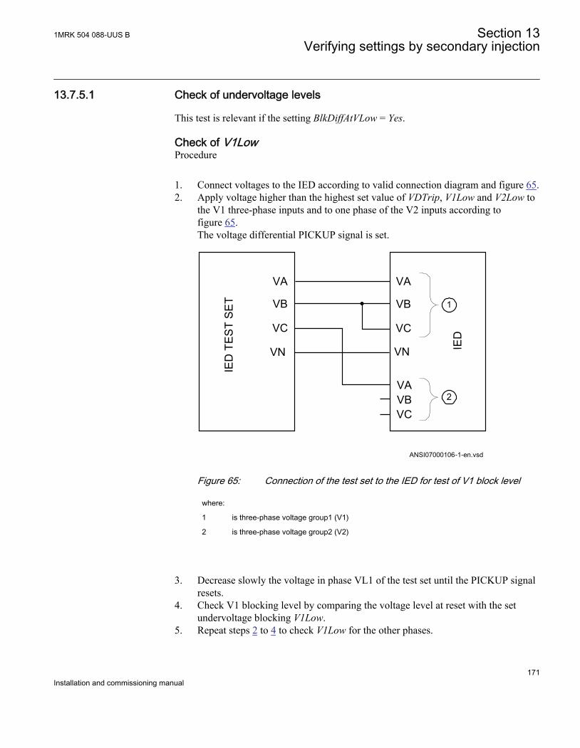
13.7.5.1 Check of undervoltage levels
This test is relevant if the setting BlkDiffAtVLow = Yes.
Check of V1LowProcedure
1. Connect voltages to the IED according to valid connection diagram and figure 65.2. Apply voltage higher than the highest set value of VDTrip, V1Low and V2Low to
the V1 three-phase inputs and to one phase of the V2 inputs according tofigure 65.The voltage differential PICKUP signal is set.
VA
VB
VC
VN
VA
VAVBVC
IED
TE
ST
SE
T
IEDANSI07000106-1-en.vsd
VB
VC
VN
1
2
ANSI07000106 V2 EN
Figure 65: Connection of the test set to the IED for test of V1 block level
where:
1 is three-phase voltage group1 (V1)
2 is three-phase voltage group2 (V2)
3. Decrease slowly the voltage in phase VL1 of the test set until the PICKUP signalresets.
4. Check V1 blocking level by comparing the voltage level at reset with the setundervoltage blocking V1Low.
5. Repeat steps 2 to 4 to check V1Low for the other phases.
1MRK 504 088-UUS B Section 13Verifying settings by secondary injection
171Installation and commissioning manual
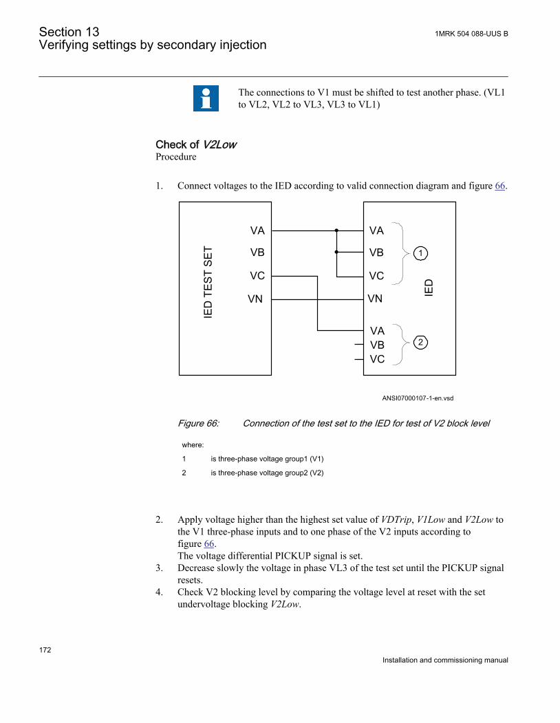
The connections to V1 must be shifted to test another phase. (VL1to VL2, VL2 to VL3, VL3 to VL1)
Check of V2LowProcedure
1. Connect voltages to the IED according to valid connection diagram and figure 66.
VA
VB
VC
VN
VA
VAVBVC
IED
TE
ST
SE
T
IED
ANSI07000107-1-en.vsd
VB
VC
VN
1
2
ANSI07000107 V2 EN
Figure 66: Connection of the test set to the IED for test of V2 block level
where:
1 is three-phase voltage group1 (V1)
2 is three-phase voltage group2 (V2)
2. Apply voltage higher than the highest set value of VDTrip, V1Low and V2Low tothe V1 three-phase inputs and to one phase of the V2 inputs according tofigure 66.The voltage differential PICKUP signal is set.
3. Decrease slowly the voltage in phase VL3 of the test set until the PICKUP signalresets.
4. Check V2 blocking level by comparing the voltage level at reset with the setundervoltage blocking V2Low.
Section 13 1MRK 504 088-UUS BVerifying settings by secondary injection
172Installation and commissioning manual
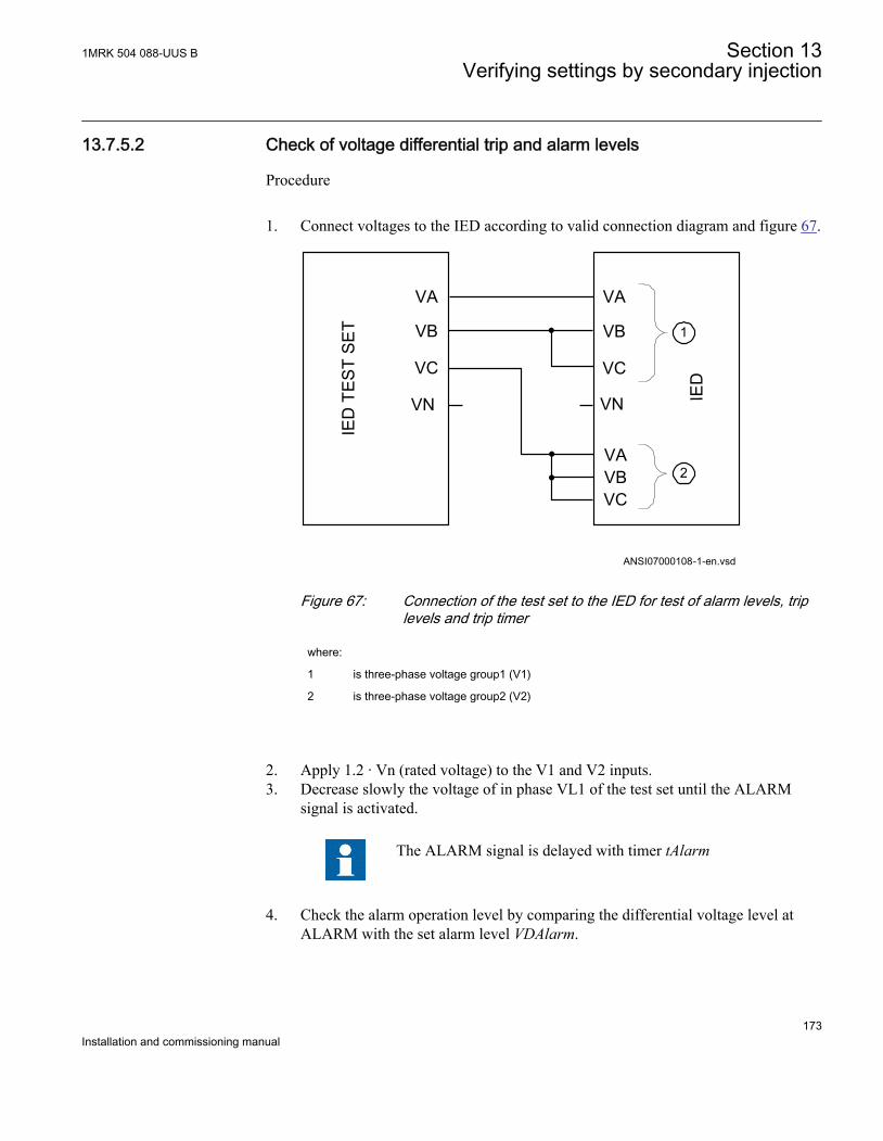
13.7.5.2 Check of voltage differential trip and alarm levels
Procedure
1. Connect voltages to the IED according to valid connection diagram and figure 67.
VA
VB
VC
VN
VA
VAVBVC
IED
TE
ST
SE
T
IED
ANSI07000108-1-en.vsd
VB
VC
VN
1
2
ANSI07000108 V2 EN
Figure 67: Connection of the test set to the IED for test of alarm levels, triplevels and trip timer
where:
1 is three-phase voltage group1 (V1)
2 is three-phase voltage group2 (V2)
2. Apply 1.2 · Vn (rated voltage) to the V1 and V2 inputs.3. Decrease slowly the voltage of in phase VL1 of the test set until the ALARM
signal is activated.
The ALARM signal is delayed with timer tAlarm
4. Check the alarm operation level by comparing the differential voltage level atALARM with the set alarm level VDAlarm.
1MRK 504 088-UUS B Section 13Verifying settings by secondary injection
173Installation and commissioning manual
5. Continue to slowly decrease the voltage until PICKUP signal is activated.6. Check the differential voltage operation level by comparing the differential
voltage level at PICKUP with the set trip level VDTrip.7. Repeat steps 1 to 2 to check the other phases.
Observe that the connections to V1 must be shifted to test another phase. (VL1 toVL2, VL2 to VL3, VL3 to VL1)
13.7.5.3 Check of trip and trip reset timers
Procdure
1. Connect voltages to the IED according to valid connection diagram and figure 67.2. Set Vn (rated voltage) to the V1 inputs and increase V2 voltage until differential
voltage is 1.5 · operating level (VDTrip).3. Switch on the test set. Measure the time from activation of the PICKUP signal
until TRIP signal is activated.4. Check the measured time by comparing it to the set trip time tTrip.5. Increase the voltage until PICKUP signal resets. Measure the time from reset of
PICKUP signal to reset of TRIP signal.6. Check the measured time by comparing it to the set trip reset time tReset.
13.7.5.4 Final adjustment of compensation for VT ratio differences
Procedure
1. With the protection in test mode, view the differential voltage service values ineach phase on the local HMI under Main menu/Test/Function status/Voltageprotection/VoltageDiff(PTOV,60)/VDCx.
The IED voltage inputs should be connected to the VTs accordingto valid connection diagram.
2. Record the differential voltages.3. Calculate the compensation factor RF_x for each phase.
For information about calculation of the compensation factor, see the applicationmanual.
4. Set the compensation factors on the local HMI under Main menu/Settings/Settings group N/Voltage protection/VoltageDiff(PTOV,60)/VDCx
5. Check that the differential voltages are close to zero.
Section 13 1MRK 504 088-UUS BVerifying settings by secondary injection
174Installation and commissioning manual
13.7.5.5 Completing the test
Continue to test another function or end the test by changing the Test mode setting toOff. Restore connections and settings to their original values, if they were changed fortesting purposes.
13.7.6 Loss of voltage check LOVPTUV (27)Prepare the IED for verification of settings as outlined in section "Overview" andsection "Preparing for test" in this chapter.
13.7.6.1 Measuring the operate limit of set values
1. Check that the input logical signals BLOCK, CBOPEN and VTSU are logical zero.2. Supply a three-phase rated voltage in all three phases and note on the local HMI
that the TRIP logical signal is equal to the logical 0.3. Switch off the voltage in all three phases.
After set tTrip time a TRIP signal appears on the corresponding binary output oron the local HMI.
Note that TRIP at this time is a pulse signal, duration should beaccording to set tPulse.
4. Inject the measured voltages to their rated values for at least set tRestore time.5. Activate the CBOPEN binary input.6. Simultaneously disconnect all the three-phase voltages from the IED.
No TRIP signal should appear.7. Inject the measured voltages to their rated values for at least set tRestore time.8. Activate the VTSU binary input.9. Simultaneously disconnect all the three-phase voltages from the tRestore.
No TRIP signal should appear.10. Reset the VTSU binary input.11. Inject the measured voltages to their rated values for at least set tRestore time.12. Activate the BLOCK binary input.13. Simultaneously disconnect all the three-phase voltages from the terminal.
No TRIP signal should appear.14. Reset the BLOCK binary input.
1MRK 504 088-UUS B Section 13Verifying settings by secondary injection
175Installation and commissioning manual
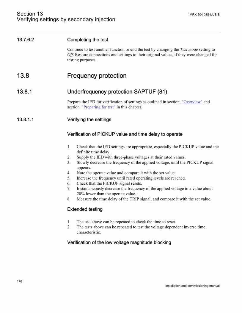
13.7.6.2 Completing the test
Continue to test another function or end the test by changing the Test mode setting toOff. Restore connections and settings to their original values, if they were changed fortesting purposes.
13.8 Frequency protection
13.8.1 Underfrequency protection SAPTUF (81)Prepare the IED for verification of settings as outlined in section "Overview" andsection "Preparing for test" in this chapter.
13.8.1.1 Verifying the settings
Verification of PICKUP value and time delay to operate
1. Check that the IED settings are appropriate, especially the PICKUP value and thedefinite time delay.
2. Supply the IED with three-phase voltages at their rated values.3. Slowly decrease the frequency of the applied voltage, until the PICKUP signal
appears.4. Note the operate value and compare it with the set value.5. Increase the frequency until rated operating levels are reached.6. Check that the PICKUP signal resets.7. Instantaneously decrease the frequency of the applied voltage to a value about
20% lower than the operate value.8. Measure the time delay of the TRIP signal, and compare it with the set value.
Extended testing
1. The test above can be repeated to check the time to reset.2. The tests above can be repeated to test the voltage dependent inverse time
characteristic.
Verification of the low voltage magnitude blocking
Section 13 1MRK 504 088-UUS BVerifying settings by secondary injection
176Installation and commissioning manual
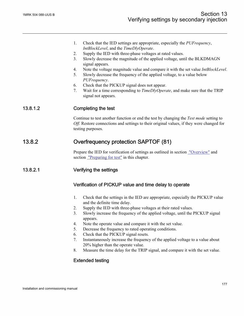
1. Check that the IED settings are appropriate, especially the PUFrequency,IntBlockLevel, and the TimeDlyOperate.
2. Supply the IED with three-phase voltages at rated values.3. Slowly decrease the magnitude of the applied voltage, until the BLKDMAGN
signal appears.4. Note the voltage magnitude value and compare it with the set value IntBlockLevel.5. Slowly decrease the frequency of the applied voltage, to a value below
PUFrequency.6. Check that the PICKUP signal does not appear.7. Wait for a time corresponding to TimeDlyOperate, and make sure that the TRIP
signal not appears.
13.8.1.2 Completing the test
Continue to test another function or end the test by changing the Test mode setting toOff. Restore connections and settings to their original values, if they were changed fortesting purposes.
13.8.2 Overfrequency protection SAPTOF (81)Prepare the IED for verification of settings as outlined in section "Overview" andsection "Preparing for test" in this chapter.
13.8.2.1 Verifying the settings
Verification of PICKUP value and time delay to operate
1. Check that the settings in the IED are appropriate, especially the PICKUP valueand the definite time delay.
2. Supply the IED with three-phase voltages at their rated values.3. Slowly increase the frequency of the applied voltage, until the PICKUP signal
appears.4. Note the operate value and compare it with the set value.5. Decrease the frequency to rated operating conditions.6. Check that the PICKUP signal resets.7. Instantaneously increase the frequency of the applied voltage to a value about
20% higher than the operate value.8. Measure the time delay for the TRIP signal, and compare it with the set value.
Extended testing
1MRK 504 088-UUS B Section 13Verifying settings by secondary injection
177Installation and commissioning manual
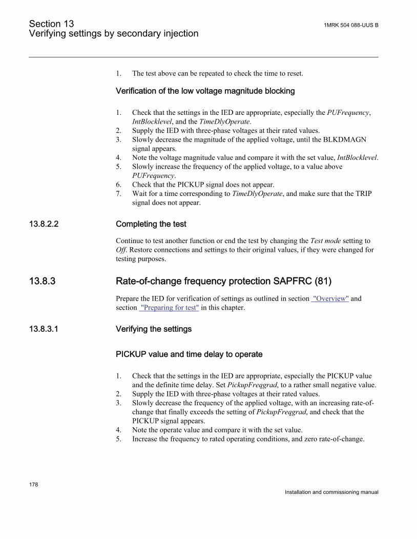
1. The test above can be repeated to check the time to reset.
Verification of the low voltage magnitude blocking
1. Check that the settings in the IED are appropriate, especially the PUFrequency,IntBlocklevel, and the TimeDlyOperate.
2. Supply the IED with three-phase voltages at their rated values.3. Slowly decrease the magnitude of the applied voltage, until the BLKDMAGN
signal appears.4. Note the voltage magnitude value and compare it with the set value, IntBlocklevel.5. Slowly increase the frequency of the applied voltage, to a value above
PUFrequency.6. Check that the PICKUP signal does not appear.7. Wait for a time corresponding to TimeDlyOperate, and make sure that the TRIP
signal does not appear.
13.8.2.2 Completing the test
Continue to test another function or end the test by changing the Test mode setting toOff. Restore connections and settings to their original values, if they were changed fortesting purposes.
13.8.3 Rate-of-change frequency protection SAPFRC (81)Prepare the IED for verification of settings as outlined in section "Overview" andsection "Preparing for test" in this chapter.
13.8.3.1 Verifying the settings
PICKUP value and time delay to operate
1. Check that the settings in the IED are appropriate, especially the PICKUP valueand the definite time delay. Set PickupFreqgrad, to a rather small negative value.
2. Supply the IED with three-phase voltages at their rated values.3. Slowly decrease the frequency of the applied voltage, with an increasing rate-of-
change that finally exceeds the setting of PickupFreqgrad, and check that thePICKUP signal appears.
4. Note the operate value and compare it with the set value.5. Increase the frequency to rated operating conditions, and zero rate-of-change.
Section 13 1MRK 504 088-UUS BVerifying settings by secondary injection
178Installation and commissioning manual
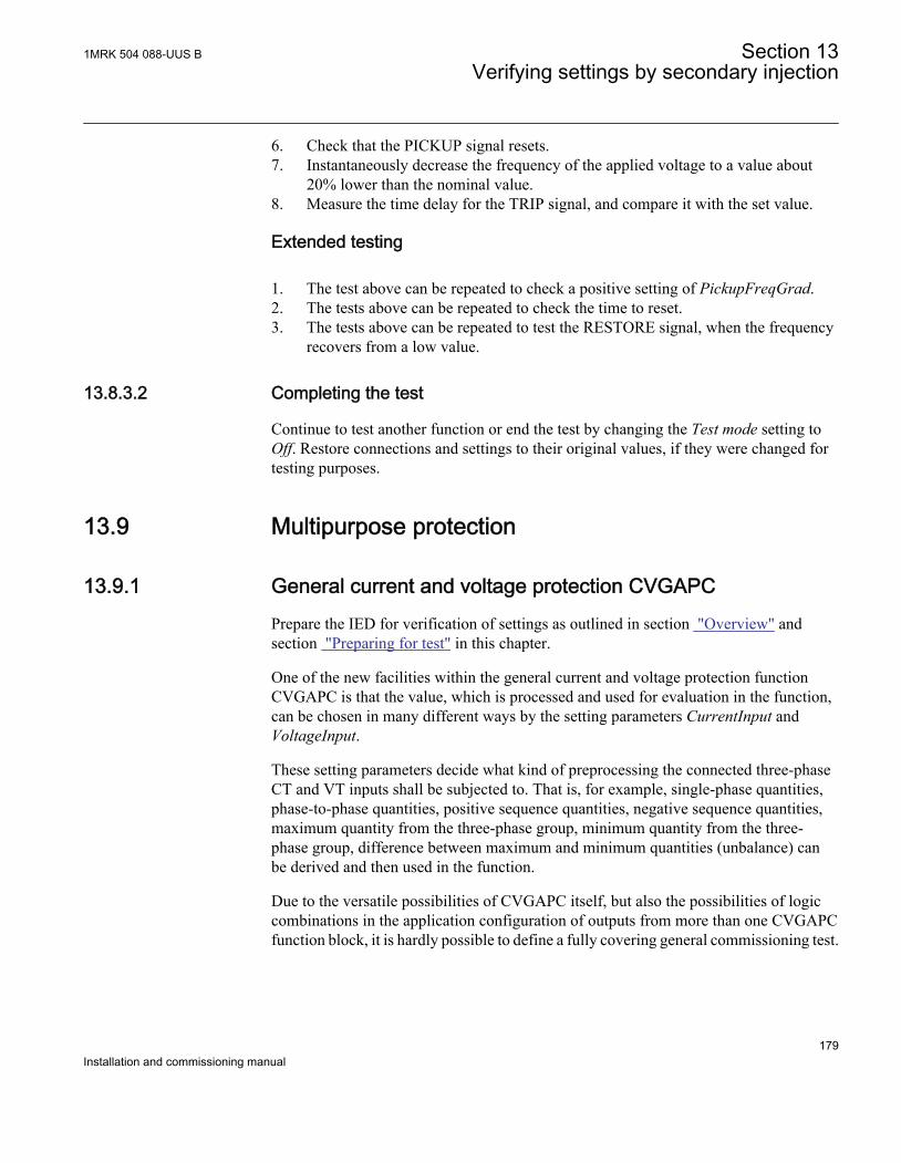
6. Check that the PICKUP signal resets.7. Instantaneously decrease the frequency of the applied voltage to a value about
20% lower than the nominal value.8. Measure the time delay for the TRIP signal, and compare it with the set value.
Extended testing
1. The test above can be repeated to check a positive setting of PickupFreqGrad.2. The tests above can be repeated to check the time to reset.3. The tests above can be repeated to test the RESTORE signal, when the frequency
recovers from a low value.
13.8.3.2 Completing the test
Continue to test another function or end the test by changing the Test mode setting toOff. Restore connections and settings to their original values, if they were changed fortesting purposes.
13.9 Multipurpose protection
13.9.1 General current and voltage protection CVGAPCPrepare the IED for verification of settings as outlined in section "Overview" andsection "Preparing for test" in this chapter.
One of the new facilities within the general current and voltage protection functionCVGAPC is that the value, which is processed and used for evaluation in the function,can be chosen in many different ways by the setting parameters CurrentInput andVoltageInput.
These setting parameters decide what kind of preprocessing the connected three-phaseCT and VT inputs shall be subjected to. That is, for example, single-phase quantities,phase-to-phase quantities, positive sequence quantities, negative sequence quantities,maximum quantity from the three-phase group, minimum quantity from the three-phase group, difference between maximum and minimum quantities (unbalance) canbe derived and then used in the function.
Due to the versatile possibilities of CVGAPC itself, but also the possibilities of logiccombinations in the application configuration of outputs from more than one CVGAPCfunction block, it is hardly possible to define a fully covering general commissioning test.
1MRK 504 088-UUS B Section 13Verifying settings by secondary injection
179Installation and commissioning manual
13.9.1.1 Built-in overcurrent feature (non-directional)
Procedure
1. Go to Main menu/Test/Function test modes/Multipurpose protection/GeneralCurrentVoltage(GAPC)/GFx and make sure that CVGAPC to be testedis unblocked and other functions that might disturb the evaluation of the test areblocked.
2. Connect the test set for injection of three-phase currents to the appropriate currentterminals of the IED in the 670 series.
3. Inject current(s) in a way that relevant measured current (according to settingparameter CurrentInput) is created from the test set. Increase the current(s) untilthe low set stage operates and check against the set operate value.
4. Decrease the current slowly and check the reset value.5. Block high set stage if the injection current will activate the high set stage when
testing the low set stage according to below.6. Connect a TRIP output contact to the timer.7. Set the current to 200% of the operate value of low set stage, switch on the
current and check the time delay.For inverse time curves, check the operate time at a current equal to 110% of theoperate current at t_MinTripDelay.
8. Check that TRIP and PICKUP contacts operate according to the configuration logic.9. Release the blocking of the high set stage and check the operate and reset value
and the time delay for the high set stage in the same way as for the low set stage.10. Finally check that PICKUP and TRIP information is stored in the event menu.
Information on how to use the event menu is found in theoperator's manual.
13.9.1.2 Overcurrent feature with current restraint
The current restraining value has also to be measured or calculated and the influenceon the operation has to be calculated when the testing of the operate value is done.
Procedure
1. Operate value measurementThe current restraining value has also to be measured or calculated and theinfluence on the operation has to be calculated when the testing of the operatevalue is done.
Section 13 1MRK 504 088-UUS BVerifying settings by secondary injection
180Installation and commissioning manual
13.9.1.3 Overcurrent feature with voltage restraint
Procedure
1. Connect the test set for injection of three-phase currents and three-phase voltagesto the appropriate current and voltage terminals of the IED.
2. Inject current(s) and voltage(s) in a way that relevant measured (according tosetting parameter CurrentInput and VoltageInput) currents and voltages arecreated from the test set.Overall check in principal as above (non-directional overcurrent feature)
3. Operate value measurementThe relevant voltage restraining value (according to setting parameterVoltageInput) has also to be injected from the test set and the influence on theoperate value has to be calculated when the testing the operate value is done.
4. Operate time measurementDefinite times may be tested as above (non-directional overcurrent feature). Forinverse time characteristics the PICKUP value (to which the overcurrent ratio hasto be calculated) is the actual pickup value as got with actual restraining from thevoltage restraining quantity.
13.9.1.4 Overcurrent feature with directionality
Please note that the directional characteristic can be set in two different ways either justdependent on the angle between current and polarizing voltage (setting parameterDirPrinc_OC1 or DirPrinc_OC2 set to or in a way that the operate value also isdependent on the angle between current and polarizing voltage according to the I ·cos(F) law (setting parameter DirPrincOC1 or DirPrincOC2 set to I · cos(F). This hasto be known if a more detailed measurement of the directional characteristic is made,than the one described below.
Procedure
1. Connect the test set for injection of three-phase currents and three-phase voltagesto the appropriate current and voltage terminals of the IED.
2. Inject current(s) and voltage(s) in a way that relevant measured (according tosetting parameter CurrentInput and VoltageInput) currents and voltages arecreated from the test set.
3. Set the relevant measuring quantity current to lag or lead (lag for negative RCAangle and lead for positive RCA angle) the relevant polarizing quantity voltageby an angle equal to the set IED characteristic angle (rca-dir) when forwarddirectional feature is selected and the CTWYEpoint configuration parameter is setto ToObject.
1MRK 504 088-UUS B Section 13Verifying settings by secondary injection
181Installation and commissioning manual
If reverse directional feature is selected or CTWYEpoint configuration parameteris set to FromObject, the angle between current and polarizing voltage shall beset equal to rca-dir+180°.
4. Overall check in principal as above (non-directional overcurrent feature)5. Reverse the direction of the injection current and check that the protection does
not operate.6. Check with low polarization voltage that the feature becomes non-directional,
blocked or with memory according to the setting.
13.9.1.5 Over/Undervoltage feature
Procedure
1. Connect the test set for injection three-phase voltages to the appropriate voltageterminals of the IED.
2. Inject voltage(s) in a way that relevant measured (according to setting parameterVoltageInput) voltages are created from the test set.
3. Overall check in principal as above (non-directional overcurrent feature) andcorrespondingly for the undervoltage feature.
13.9.1.6 Completing the test
Continue to test another function or end the test by changing the Test mode setting toOff. Restore connections and settings to their original values, if they were changed fortesting purposes.
13.10 Secondary system supervision
13.10.1 Current circuit supervision CCSRDIF (87)Prepare the IED for verification of settings as outlined in section "Overview" andsection "Preparing for test" in this chapter.
The Current circuit supervision function CCSRDIF (87) is conveniently tested with thesame three-phase test set as used when testing the measuring functions in the IED.
The condition for this procedure is that the setting of IMinOp is lower than the settingof Pickup_Block.
13.10.1.1 Verifying the settings
Section 13 1MRK 504 088-UUS BVerifying settings by secondary injection
182Installation and commissioning manual
1. Check the input circuits and the operate value of the IMinOp current leveldetector by injecting current, one phase at a time.
2. Check the phase current blocking function for all three phases by injectioncurrent, one phase at a time. The output signals shall reset with a delay of 1second when the current exceeds 1.5 · IBase.
3. Inject a current 0.9 · IBase to phase A and a current 0.15 · IBase to the referencecurrent input I5.
4. Decrease slowly the current to the reference current input and check that blockingis obtained when the current is about 0.1 · IBase.
13.10.1.2 Completing the test
Continue to test another function or end the test by changing the Test mode setting toOff. Restore connections and settings to their original values, if they were changed fortesting purposes.
13.10.2 Fuse failure supervision SDDRFUFPrepare the IED for verification of settings as outlined in section "Overview" andsection "Preparing for test" in this chapter.
The verification is divided in two main parts. The first part is common to all fusefailure supervision options, and checks that binary inputs and outputs operate asexpected according to actual configuration. In the second part the relevant set operatevalues are measured.
13.10.2.1 Checking that the binary inputs and outputs operate as expected
Procedure
1. Simulate normal operating conditions with the three-phase currents in phase withtheir corresponding phase voltages and with all of them equal to their rated values.
2. Connect the nominal dc voltage to the 89bS binary input.• The signal BLKV should appear with almost no time delay.• No signals BLKZ and 3PH should appear on the IED.• Only the distance protection function operates.• No other undervoltage-dependent functions must operate.
3. Disconnect the dc voltage from the 89b binary input terminal.4. Connect the nominal dc voltage to the MCBOP binary input.
• The BLKV and BLKZ signals should appear without any time delay.• No undervoltage-dependent functions must operate.
1MRK 504 088-UUS B Section 13Verifying settings by secondary injection
183Installation and commissioning manual
5. Disconnect the dc voltage from the MCBOP binary input terminal.6. Disconnect one of the phase voltages and observe the logical output signals on
the binary outputs of the IED.. BLKV and BLKZ signals should simultaneouslyappear.
7. After more than 5 seconds disconnect the remaining two-phase voltages and allthree currents.• There should be no change in the high status of the output signals BLKV
and BLKZ.• The signal 3PH will appear.
8. Establish normal voltage and current operating conditions simultaneously andobserve the corresponding output signals.They should change to logical 0 as follows:• Signal 3PH after about 25ms• Signal BLKV after about 50ms• Signal BLKZ after about 200ms
13.10.2.2 Measuring the operate value for the negative sequence function
Measure the operate value for the negative sequence function, if included in the IED.
Procedure
1. Simulate normal operating conditions with the three-phase currents in phase withtheir corresponding phase voltages and with all of them equal to their rated values.
2. Slowly decrease the measured voltage in one phase until the BLKV signal appears.3. Record the measured voltage and calculate the corresponding negative-sequence
voltage according to the equation.Observe that the voltages in the equation are phasors.
223 A B CV V a V a V× = + × + ×
EQUATION1818-ANSI V1 EN (Equation 13)
Where:
A B CandV V VEQUATION1820-ANSI V1 EN
= the measured phase voltages
a 1 ej 2 p×
3-----------
× 0 5 j 32
-------+,–= =EQUATION709 V1 EN
4. Compare the result with the set value (consider that the set value 3V2PU is inpercentage of the base voltage UBase) of the negative-sequence operating voltage.
Section 13 1MRK 504 088-UUS BVerifying settings by secondary injection
184Installation and commissioning manual
13.10.2.3 Measuring the operate value for the zero-sequence function
Measure the operate value for the zero-sequence function, if included in the IED.
Procedure
1. Simulate normal operating conditions with the three-phase currents in phase withtheir corresponding phase voltages and with all of them equal to their rated values.
2. Slowly decrease the measured voltage in one phase until the BLKV signal appears.3. Record the measured voltage and calculate the corresponding zero-sequence
voltage according to the equation.Observe that the voltages in the equation are phasors.
03 A B CV V V V× = + +EQUATION1819-ANSI V1 EN (Equation 16)
Where:
A B CandV V VEQUATION1820-ANSI V1 EN
= the measured phase voltages.
4. Compare the result with the set value (consider that the set value 3V0Pickup is inpercentage of the base voltage of the zero-sequence operating voltage.
13.10.2.4 Checking the operation of the dv/dt and di/dt based function
Check the operation of the dv/dt and di/dt based function, if included in the IED.
Procedure
1. Simulate normal operating conditions with the three-phase currents in phase withtheir corresponding phase voltages and with all of them equal to their rated values.
2. Connect the nominal dc voltage to the 52a binary input.3. Change the voltages and currents in all three phases simultaneously.
The voltage change should be greater then set DVPU and the current changeshould be less than the set DIPU.• The BLKV and BLKZ signals appear without any time delay. The BLKZ
signal will be activated, only if the internal deadline detection is notactivated at the same time.
• 3PH should appear after 5 seconds, if the remaining voltage levels are lowerthan the set VDLDPU of the DLD function.
4. Apply normal conditions as in step 3.The BLKV, BLKZ and 3PH signals should reset, if activated, see step 1.
5. Change the voltages and currents in all three phases simultaneously.
1MRK 504 088-UUS B Section 13Verifying settings by secondary injection
185Installation and commissioning manual
The voltage change should be greater than set DVPU and the current changeshould be greater than the set DIPU.The BLKV, BLKZ and 3PH signals should not appear.
6. Disconnect the dc voltage to the 52a binary input.7. Apply normal conditions as in step 1.8. Repeat step 3.9. Connect the nominal voltages in all three phases and feed a current below the
operate level in all three phases.10. Keep the current constant. Disconnect the voltage in all three phases simultaneously.
13.10.2.5 Completing the test
Continue to test another function or end the test by changing the Test mode setting toOff. Restore connections and settings to their original values, if they were changed fortesting purposes.
13.11 Control
13.11.1 Synchronism check, energizing check, and synchronizingSESRSYN (25)
This section contains instructions on how to test the synchronism check, energizingcheck, and synchronizing function SESRSYN (25) for single and double CB and forbreaker-and-a-half arrangements.
This section contains instructions on how to test the synchrochecksynchronism checkand energizing check for single CB with or without the synchronizing function.
Prepare the IED for verification of settings as outlined in section "Overview"andsection "Preparing for test" in this chapter.
At commissioning and periodical checks, the functions shall be tested with the usedsettings. To test a specific function, it might be necessary to change some settingparameters, for example:
• AutoEnerg = On/Off/DLLB/DBLL/Both• ManEnerg = Off• Operation = Off, On• Activation of the voltage selection function if applicable
Section 13 1MRK 504 088-UUS BVerifying settings by secondary injection
186Installation and commissioning manual
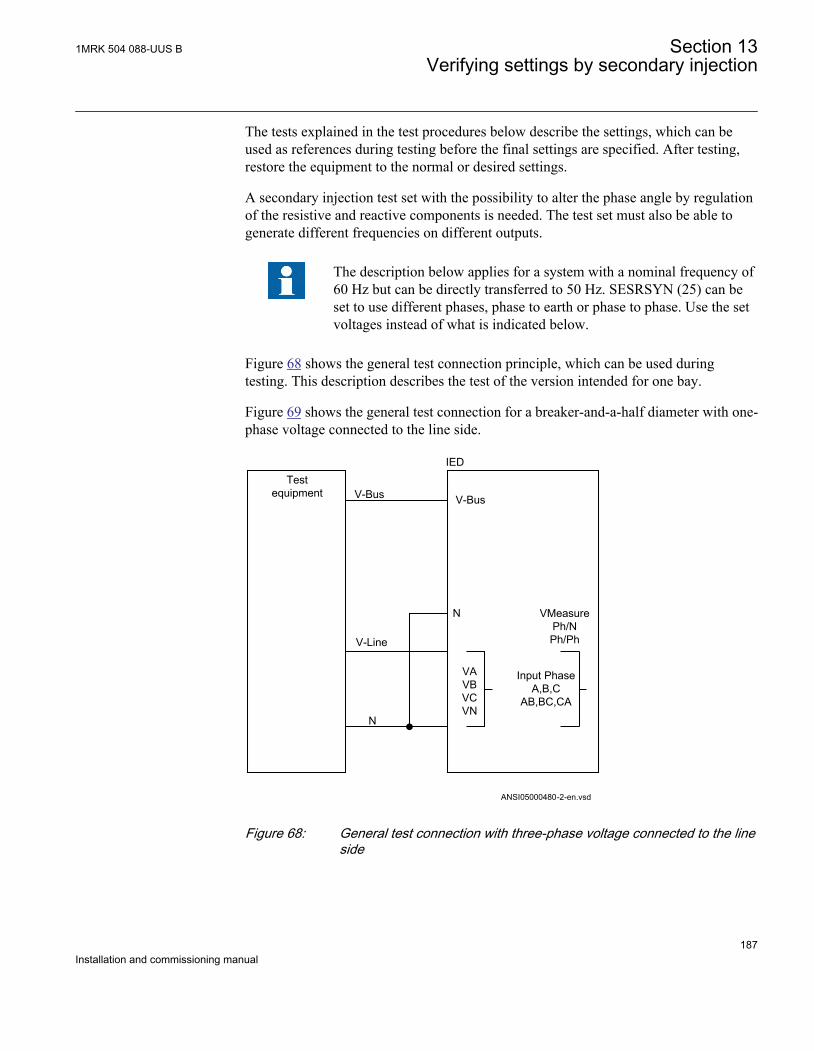
The tests explained in the test procedures below describe the settings, which can beused as references during testing before the final settings are specified. After testing,restore the equipment to the normal or desired settings.
A secondary injection test set with the possibility to alter the phase angle by regulationof the resistive and reactive components is needed. The test set must also be able togenerate different frequencies on different outputs.
The description below applies for a system with a nominal frequency of60 Hz but can be directly transferred to 50 Hz. SESRSYN (25) can beset to use different phases, phase to earth or phase to phase. Use the setvoltages instead of what is indicated below.
Figure 68 shows the general test connection principle, which can be used duringtesting. This description describes the test of the version intended for one bay.
Figure 69 shows the general test connection for a breaker-and-a-half diameter with one-phase voltage connected to the line side.
Testequipment
VMeasurePh/NPh/Ph
ANSI05000480-2-en.vsd
V-Bus
V-Line
N
IED
V-Bus
N
VAVBVCVN
Input PhaseA,B,C
AB,BC,CA
ANSI05000480 V2 EN
Figure 68: General test connection with three-phase voltage connected to the lineside
1MRK 504 088-UUS B Section 13Verifying settings by secondary injection
187Installation and commissioning manual
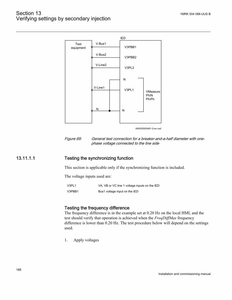
V-Bus1
V-Line1
N
Testequipment
IED
V3PBB1
N
ANSI05000481-2-en.vsd
N
VMeasure Ph/NPh/Ph
V-Bus2
V-Line2
V3PBB2
V3PL2
V3PL1
ANSI05000481 V2 EN
Figure 69: General test connection for a breaker-and-a-half diameter with one-phase voltage connected to the line side
13.11.1.1 Testing the synchronizing function
This section is applicable only if the synchronizing function is included.
The voltage inputs used are:
V3PL1 VA, VB or VC line 1 voltage inputs on the IED
V3PBB1 Bus1 voltage input on the IED
Testing the frequency differenceThe frequency difference is in the example set at 0.20 Hz on the local HMI, and thetest should verify that operation is achieved when the FreqDiffMax frequencydifference is lower than 0.20 Hz. The test procedure below will depend on the settingsused.
1. Apply voltages
Section 13 1MRK 504 088-UUS BVerifying settings by secondary injection
188Installation and commissioning manual
1.1. V-Line = 100% VBase1.2. f-line = 60.0 Hz and V-Bus = 100% VBase1.3. f-bus = 60.2 Hz
2. Check that a closing pulse is submitted and at closing angle less than 2 degreesfrom phase equality. Modern test sets will evaluate this automatically.
3. Repeat with3.1. V-Bus = 80% VBase3.2. f-bus = 60.25 Hz, to verify that the function does not operate when
frequency difference is above limit.4. Repeat with different frequency differences for example, 100 mHz with f-bus
nominal and line leading and for example 20 mHz (or just above FreqDiffMin) toverify that independent of frequency difference the closing pulse occurs within 2degrees.
5. Verify that the closing command is not issued when the frequency difference isless than the set value FreqDiffMin.
13.11.1.2 Testing the synchronizing check
During the test of SESRSYN (25) for a single bay arrangement, these voltage inputsare used:
V-Line VA, VB or VC voltage input on the IED
V-Bus V5 voltage input on the IED
Testing the voltage differenceSet the voltage difference at 15% VBase on the local HMI, and the test should checkthat operation is achieved when the voltage difference VDiffSC is lower than 15%VBase.
The settings used in the test shall be final settings. The test shall be adapted to sitesetting values instead of values in the example below.
Test with no voltage difference between the inputs.
Test with a voltage difference higher than the set VDiffSC
1MRK 504 088-UUS B Section 13Verifying settings by secondary injection
189Installation and commissioning manual

1. Apply voltages V-Line (for example) = 80% VBase and V-Bus = 80% VBase.2. Check that the AUTOSYOK and MANSYOK outputs are activated.3. The test can be repeated with different voltage values to verify that the function
operates within the set VDiffSC. Check with both V-Line and V-Bus respectivelylower than the other.
4. Increase the V-Bus to 110% VBase, and the V-Line = 90% VBase and also theopposite condition.
5. Check that the two outputs for manual and auto synchronism are not activated.
Testing the phase angle differenceThe phase angle differences PhaseDiffM and PhaseDiffA respectively are set to theirfinal settings and the test should verify that operation is achieved when the phase angledifference is lower than this value both leading and lagging.
Test with no voltage difference
1. Apply voltages V-Line (for example) = 100% VBase and V-Bus = 100% VBase,with a phase difference equal to 0 degrees and a frequency difference lower thanFreqDiffA and FreqDiffM
2. Check that the AUTOSYOK and MANSYOK outputs are activated.The test can be repeated with other phase difference values to verify that thefunction operates for values lower than the set ones, PhaseDiffM andPhaseDiffA. By changing the phase angle on the voltage connected to V-Bus,between ± dφ degrees, the user can check that the two outputs are activated for aphase difference lower than the set value. It should not operate for other values.See figure 70.
Section 13 1MRK 504 088-UUS BVerifying settings by secondary injection
190Installation and commissioning manual
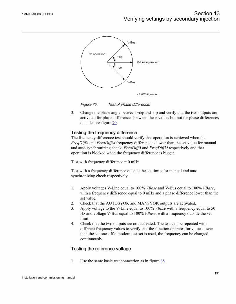
+dj
-dj
V-Bus
V-Line operation
V-Bus
No operation
en05000551_ansi.vsdANSI05000551 V1 EN
Figure 70: Test of phase difference.
3. Change the phase angle between +dφ and -dφ and verify that the two outputs areactivated for phase differences between these values but not for phase differencesoutside, see figure 70.
Testing the frequency differenceThe frequency difference test should verify that operation is achieved when theFreqDiffA and FreqDiffM frequency difference is lower than the set value for manualand auto synchronizing check, FreqDiffA and FreqDiffM respectively and thatoperation is blocked when the frequency difference is bigger.
Test with frequency difference = 0 mHz
Test with a frequency difference outside the set limits for manual and autosynchronizing check respectively.
1. Apply voltages V-Line equal to 100% VBase and V-Bus equal to 100% VBase,with a frequency difference equal to 0 mHz and a phase difference lower than theset value.
2. Check that the AUTOSYOK and MANSYOK outputs are activated.3. Apply voltage to the V-Line equal to 100% VBase with a frequency equal to 50
Hz and voltage V-Bus equal to 100% VBase, with a frequency outside the setlimit.
4. Check that the two outputs are not activated. The test can be repeated withdifferent frequency values to verify that the function operates for values lowerthan the set ones. If a modern test set is used, the frequency can be changedcontinuously.
Testing the reference voltage
1. Use the same basic test connection as in figure 68.
1MRK 504 088-UUS B Section 13Verifying settings by secondary injection
191Installation and commissioning manual
The voltage difference between the voltage connected to V-Bus and V-Lineshould be 0%, so that the AUTOSYOK and MANSYOK outputs are activated first.
2. Change the V-Line voltage connection to V-Line2 without changing the settingon the local HMI. Check that the two outputs are not activated.
13.11.1.3 Testing the energizing check
During the test of the energizing check function for a single bay arrangement, thesevoltage inputs are used:
V-Line VA, VB or VC voltage input on the IED
V-Bus Bus voltage input on the IED
GeneralWhen testing the energizing check function for the applicable bus, arrangement shallbe done for the energizing check functions. The voltage is selected by activation ofdifferent inputs in the voltage selection logic.
The test shall be performed according to the settings for the station. Test thealternatives below that are applicable.
Testing the dead line live bus (DLLB)The test should verify that the energizing check function operates for a low voltage onthe V-Line and for a high voltage on the V-Bus. This corresponds to the energizing ofa dead line to a live bus.
1. Apply a single-phase voltage 100% VBase to the U-Bus, and a single-phasevoltage 30% VBase to the V-Line.
2. Check that the AUTOENOK and MANENOK outputs are activated.3. Increase the V-Line to 60% VBase and V-Bus to be equal to 100% VBase. The
outputs should not be activated.4. The test can be repeated with different values on the V-Bus and the V-Line.
Testing the dead bus live line (DBLL)The test should verify that the energizing check function operates for a low voltage onthe V-Bus and for a high voltage on the V-Line. This corresponds to an energizing of adead bus from a live line.
Section 13 1MRK 504 088-UUS BVerifying settings by secondary injection
192Installation and commissioning manual
1. Verify the local HMI settings AutoEnerg or ManEnerg to be DBLL.2. Apply a single-phase voltage of 30% VBase to the V-Bus and a single-phase
voltage of 100% VBase to the V-Line.3. Check that the AUTOENOK and MANENOK outputs are activated.4. Decrease the V-Line to 60% VBase and keep the V-Bus equal to 30% VBase. The
outputs should not be activated.5. The test can be repeated with different values on the V-Bus and the V-Line.
Testing both directions (DLLB or DBLL)Procedure
1. Verify the local HMI settings AutoEnerg or ManEnerg to be Both.2. Apply a single-phase voltage of 30% VBase to the V-Line and a single-phase
voltage of 100% VBase to the V-Bus.3. Check that the AUTOENOK and MANENOK outputs are activated.4. Change the connection so that the V-Line is equal to100% VBase and the V-Bus
is equal to 30% VBase. The outputs should still be activated.5. The test can be repeated with different values on the V-Bus and the V-Line.
Testing the dead bus dead line (DBDL)The test should verify that the energizing check function operates for a low voltage onboth the V-Bus and the V-Line, that is, closing of the breaker in a non-energizedsystem. Test is valid only when this function is used.
1. Verify the local HMI setting AutoEnerg to be Disabled and ManEnerg to beDBLL.
2. Set the parameter ManEnergDBDL to Enabled.3. Apply a single-phase voltage of 30% VBase to the U-Bus and a single-phase
voltage of 30% VBase to the V-Line.4. Check that the MANENOK output is activated.5. Increase the V-Bus to 80% VBase and keep the V-Line equal to 30% VBase. The
outputs should not be activated.6. Repeat the test with ManEnerg set to DLLB with different values on the V-Bus
and the V-Line voltage.
13.11.1.4 Testing the voltage selection
Testing the voltage selection for single CB arrangementsThis test should verify that the correct voltage is selected for the measurement in theenergizing check function used in a double-bus arrangement. Apply a single-phase
1MRK 504 088-UUS B Section 13Verifying settings by secondary injection
193Installation and commissioning manual
voltage of 30% VBase to the V-Line and a single-phase voltage of 100% VBase to theV-Bus.
If the VB1/2OK inputs for the fuse failure are used, they must be activated, during testsbelow. Also verify that deactivation prevents operation and gives an alarm.
1. Connect the signals above to binary inputs and binary outputs.2. Connect the voltage inputs to the analog inputs used for each bus or line
depending of the type of busbar arrangement and verify that correct outputsignals are generated.
Testing the voltage selection for double breaker or 1½ circuit breakerdiameter when applicableThis test should verify that correct voltage is selected for the measurement in theenergizing function used for a diameter in a Breaker-and-a-half arrangement. Applysingle-phase voltages to the inputs. H means a voltage of 100% VBase and L means avoltage of 30% VBase. Verify that correct output signals are generated.
1. Connect the analog signals to the voltage inputs, in pair of two for V1 and V2.(Inputs U3P - BB1, BB2, L1, L2)
2. Activate the binary signals according to the used alternative. Verify themeasuring voltage on the synchronizing check function SESRSYN (25).Normally it can be good to verify synchronizing check with the same voltagesand phase angles on both voltages. The voltages should be verified to be availablewhen selected and not available when another input is activated so connect onlyone voltage transformer reference at each time.
3. Record the voltage selection tests in a matrix table showing read values andAUTOSYOK/MANSYOK signals to document the test performed.
13.11.1.5 Completing the test
Continue to test another function or end the test by changing the Test mode setting toOff. Restore connections and settings to their original values, if they were changed fortesting purposes.
13.11.2 Apparatus control APCThe apparatus control function consists of four types of function blocks, which areconnected in a delivery-specific way between bays and to the station level. For thatreason, test the total function in a system, that is, either in a complete delivery systemas an acceptance test (FAT/SAT) or as parts of that system.
Section 13 1MRK 504 088-UUS BVerifying settings by secondary injection
194Installation and commissioning manual
If a block/unblock command is sent from remote to function, while theIED is shut down, this command will not be recognized after the startup, thus the command that was sent prior to the shut down is used. Insuch cases, where there is a mismatch, the user is advised to make acomplete cycle of block/unblock operations to align the statuses.
13.11.3 InterlockingPrepare the IED for verification of settings as outlined in section "Overview" andsection "Preparing for test" in this chapter.
The interlocking function consists of a bay-level part and a station-level part. Theinterlocking is delivery specific and is realized by bay-to-bay communication over thestation bus. For that reason, test the function in a system, that is, either in a completedelivery system as an acceptance test (FAT/SAT) or as parts of that system.
13.11.4 Voltage control VCTRPrepare the IED for verification of settings as outlined in section "Overview" andsection "Preparing for test" in this chapter.
The automatic voltage control for tap changer, single control TR1ATCC (90) is basedon a transformer configuration that consists of one tap changer on a single two-windingpower transformer.
The automatic voltage control for tap changer, parallel control TR8ATCC (90), ifinstalled, may be set to operate in Master Follower (MF) mode, or MinimiseCirculating Current (MCC) mode. The commissioning tests for each parallel controlmode are addressed separately in the following procedure.
Secondary injection of load current (IL) and secondary bus voltage (UB) equivalentquantities is required during installation and commissioning tests. The test consistsmainly of:
1. Increasing or decreasing the injected voltage or current at the analogue inputs ofthe IED.
2. Checking that the corresponding commands (Lower or Raise) are issued by thevoltage control function.
Setting confirmation is an important step for voltage control in the installation andcommissioning phase to ensure consistency of power systems base quantities, alarm/blocking conditions and parallel control settings for each transformer control function.
1MRK 504 088-UUS B Section 13Verifying settings by secondary injection
195Installation and commissioning manual
Before starting any test, verify the following settings in PCM600 or the local HMI forTR1ATCC (90), TR8ATCC (90) and TCMYLTC and TCLYLTC (84) (84).
• Confirm power system base quantities I1Base, I2Base, VBase.
Main menu/Settings/Setting Group N/Control/TransformerVoltageControl(ATCC,90)/VCSx/VCPx/General
and
Main menu/Settings/Setting Group N/Control/TransformerVoltageControl(ATCC,90)/VCSx
.
• Confirm that the setting for short circuit impedance Xr2 for TR1ATCC (90) orTR8ATCC (90) is in accordance with transformer data:• Short circuit impedance, available on the local HMI under Main menu/
Settings/General settings/Control/TransformerVoltageControl(ATCC,90)/VCSx/VCPx/Xr2.
• Confirm that the setting for TCMYLTC (84) or TCLYLTC (84) is in accordancewith transformer data:• Tap change timeout duration - effectively the maximum transformer tap
change time, tTCTimeout, available on the local HMI under Main menu/Settings/Setting Group N/Control/TransformerTapControl(YLTC,84)/TCMx/TCLx/tTCTimeout.
• Load tap changer pulse duration - required length of pulse from IED to loadtap changer, tPulseDur, available on the local HMI under Main menu/Settings/Setting Group N/Control/TransformerTapControl(YLTC,84)/TCMx/TCLx/tPulseDur.
• Transformer tap range, LowVoltTap and HighVoltTap, available on the localHMI underMain menu/Settings/General Settings/Control/TransformerTapControl(YLTC,84)/TCMx/TCLx/LowVoltTap andHighVoltTap.
• Load tap changer code type - method for digital feedback of tap position,CodeType, available on the local HMI under Main menu/Settings/ Generalsettings/Control/TransformerTapControl(YLTC,84)/TCMx/TCLx/CodeType.
During the installation and commissioning, the behavior of the voltagecontrol functions for different tests may be governed by a parametergroup, available on the local HMI under Main menu/Settings/Generalsettings/Control/TransformerVoltageControl(ATCC,90)/VCSx/VCPx. These parameter settings can cause a Total Block, Automatic
Section 13 1MRK 504 088-UUS BVerifying settings by secondary injection
196Installation and commissioning manual
Block or Alarm for a variety of system conditions including over andunder voltage, over current and tap changer failure. It is important toreview these settings and confirm the intended response of the voltagecontrol function for different secondary injection tests.
TerminologyThe busbar voltage VB is a shorter notation for the measured voltages Va, Vb, Vc orVij, where Vij is the phase-phase voltage, Vij = Vi -Vj, or Vi, where Vi is one single-phase-to-ground voltage.
IL is a shorter notation for the measured load current; it is to be used instead of the three-phase quantities Ia, Ib, Ic or the two-phase quantities Ii and Ij, or single-phase current Ii.
Also note that for simplicity, the Parameter Setting menu structuresincluded in the following procedure are referred to universally asVCP1, for example, Main menu/Settings/Setting Group N/Control/TransformerVoltageControl(ATCC,90)/VCSx/VCPx/Time/t1 andt2l.
For cases where single-mode voltage control is implemented, the Parameter Settingmenu structure includes VCS1 instead of the parallel designator VCP1.
13.11.4.1 Secondary test
The voltage control function performs basic voltage regulation by comparing acalculated load voltage (VL) against a voltage range defined by setting VDeadband(with upper and lower limits V2 and V1 respectively). The calculated load voltage VLrepresents the secondary transformer bus voltage VB adjusted for Load dropcompensation (LDC) where enabled in settings.
Note that when LDC is disabled, VB equals VL.
When the load voltage VL stays within the interval between V1 and V2, no action willbe taken.
If VL < V1 or VL > V2, a command timer will start, which is constant time or inversetime defined by setting t1 and t1Use. The command timer will operate while themeasured voltage stays outside the inner deadband (defined by settingVDeadbandInner).
1MRK 504 088-UUS B Section 13Verifying settings by secondary injection
197Installation and commissioning manual
If VL remains outside of the voltage range defined by VDeadband and the commandtimer expires, the voltage control will execute a raise or lower command to thetransformer tap changer. This command sequence will be repeated until VL is broughtback within the inner deadband range.
13.11.4.2 Check the activation of the voltage control operation
1. Confirm Transformer Tap Control = On and Transformer Voltage Control = On• Direct tap change control
Main menu/Settings/Setting Group N/Control/TransformerTapChanger(YLTC,84)/TCMx/TCLx/Operation• Automatic transformer voltage control
Main menu/Settings/Setting Group N/Control/TransformerVoltageControl(ATCC,90)/VCSx/VCPx/General/Operation• Enable Tap Command
Main menu/Settings/General settings/Control/TransformerTapChanger(YLTC,84)/TCMx/TCLx/EnabTapCmdWhile the test set is connected to the IED but no voltage is applied, the voltagecontrol functions will detect an undervoltage condition that may result in analarm or blocking of the voltage-control operation. These conditions will beshown on the local HMI.
2. Apply the corresponding voltageConfirm the analog measuring mode prior to undertaking secondary injection(positive sequence, phase-phase, or phase-ground). This measuring mode isdefined in the local HMI under Main menu/Settings/Setting Group N/Control/TransformerVoltageControl(ATCC,90)/VCSx/VCPx/General/MeasModeThe application of nominal voltage VSet according to set MeasMode to the IEDsshould cause the alarm or blocking condition for undervoltage to reset.
13.11.4.3 Check the normal voltage regulation function
1. Review the settings for VDeadband (based on percentage of nominal bus voltage)and calculate the upper (V2) and lower (V1) voltage regulation limits for which atap change command will be issued.
2. Review the expected time for first (t1) and subsequent (t2) tap change commandsfrom the voltage control function on the local HMI under Main menu/Settings/
Section 13 1MRK 504 088-UUS BVerifying settings by secondary injection
198Installation and commissioning manual
Setting Group N/Control/TransformerVoltageControl(ATCC,90)/VCSx/VCPx/Time/t1 and t2l
3. Lower the voltage 1% below V1 and wait for the issue of a Raise command fromthe voltage control after the expiry of a constant or inverse time delay set by t1.Detection of this command will involve locating the allocated binary output for araise pulse command in the Signal Matrix in PCM600 and monitoring a positivefrom this output.
4. After the issue of the raise command, return the applied voltage to VSet (nominalvalue).
5. Raise the voltage 1% above the upper deadband limit V2 and wait for the issue ofa lower command from the voltage control after the expiry of a constant orinverse time delay set by t1. Detection of this command will involve locating theallocated binary output for a low pulse command in the Signal Matrix in PCM600and monitoring a positive from this output.
6. Return the applied voltage to VSet.
13.11.4.4 Check the undervoltage block function
1. Confirm the setting for Vblock, nominally at 80% of rated voltage.2. Confirm the voltage control function response to an applied voltage below
Vblock, by reviewing the setting in the local HMI under Main menu/Settings/General settings/Control/TransformerVoltageControl(ATCC,90)/VCSx/VCPx/UVBk that may cause an alarm, total or automatic block of the voltagecontrol function to be displayed on the local HMI.
3. Apply a voltage slightly below Vblock and confirm the response of the voltagecontrol function.
13.11.4.5 Check the upper and lower busbar voltage limit
1. Confirm the settings for Vmin and Vmax in the local HMI under Main menu/Settings/Setting group N/Control/TransformerVoltageControl(ATCC,90)/VCSx/VCPx/Voltage/Umax or Umin
2. Confirm the voltage control function response to an applied voltage below Vminand above Vmax, by reviewing the settings in the local HMI under Main menu/Settings/General settings/Control/TransformerVoltageControl(ATCC,90)/VCSx/VCPx/UVPartBk and Main menu/General Settings/Control/TransformerVoltageControl/VCSx/VCPx/OVPartBk. These conditions maycause an alarm, total or automatic block of the voltage control function to bedisplayed on the local HMI.
3. Decrease the injected voltage slightly below the Vmin value and check for thecorresponding blocking or alarm condition on the local HMI. For an alarm
1MRK 504 088-UUS B Section 13Verifying settings by secondary injection
199Installation and commissioning manual
condition, the voltage regulation function is not blocked and a raise commandshould be issued from the IED.
4. Increase the applied voltage slightly above the Vmax value and check for thecorresponding blocking or alarm condition on the local HMI. For an alarmcondition, the voltage regulation function is not blocked and a lower commandshould be issued from the IED.
13.11.4.6 Check the overcurrent block function
1. Confirm the setting for Iblock in the local HMI under Main menu/Settings/Setting group N/Control/TransformerVoltageControl(ATCC,91)/VCSx/VCPx/TCCtrl/Iblock
2. Confirm the voltage control function response to an applied current above Iblock,by reviewing the settings in the local HMI under Main menu/Settings/Generalsettings/Control/TransformerVoltageControl(ATCC,91)/VCSx/VCPx/OVPartBk. This condition may cause an alarm, total or automatic block of thevoltage control function to be displayed on the local HMI.
3. Inject a current higher than the Iblock setting and confirm the alarm or blockingcondition is present on the local HMI. If an automatic or total blocking conditionoccurs, change the applied secondary voltage and confirm that no tap changecommands are issued from the associated binary outputs. This situation can alsobe confirmed through reviewing the disturbance and service reports on the localHMI.
13.11.4.7 Single transformer
Load drop compensation
1. Confirm that OperationLDC is set to Enabled.2. Confirm settings for Rline and Xline.3. Calculate the expected load voltage VL (displayed as a measured value on the
local HMI) based on secondary injection of transformer secondary voltage (VB =VSet) and rated load current (IL = I1Base), in accordance with equation 18.
Section 13 1MRK 504 088-UUS BVerifying settings by secondary injection
200Installation and commissioning manual
VL = VB - (Rline + jXline) . IL
EQUATION2081-ANSI V2 EN (Equation 18)
where:
VL, IL = Re(IL) + jlm(IL) are complex phase quantities
When all secondary phase-to-ground voltages are available, use the positive-sequence components of voltage and current. By separation of real and imaginaryparts:
, , , ,vl re vb re rline il re xline il im= - × + ×
EQUATION2083-ANSI V1 EN (Equation 19)
, , , ,vl im vb im xline il re rline il im= - × - ×
EQUATION2085-ANSI V1 EN (Equation 20)
where:
vb is the complex value of the busbar voltage
il is the complex value of the line current (secondary side)
rline is the value of the line resistance
xline is the value of the line reactance
For comparison with the set-point value, the modulus of UL are according toequation 21.
¦ VL¦ = (vl , re)2 + (vl , im)2
EQUATION2087-ANSI V2 EN (Equation 21)
4. Inject voltage for VB equal to setting VSet.5. Inject current equal to rated current I2Base.6. Confirm on the local HMI that service values for bus voltage and load current are
equal to injected quantities.7. Confirm that the calculated value for load voltage, displayed on the local HMI, is
equal to that derived through hand calculations.8. When setting OperationLDC set to Enabled, the voltage regulation algorithm
uses the calculated value for load voltage as the regulating quantity to compareagainst VSet and the voltage deadband limits VDeadband and VDeadbandInner.
9. While injecting rated current I2Base into the IED, inject a quantity for VB that isslightly higher then VSet + |(Rline+jXLine)·IL|. This will ensure that the regulating
1MRK 504 088-UUS B Section 13Verifying settings by secondary injection
201Installation and commissioning manual
voltage VL is higher than VSet, and hence no tap change command should beissued from the IED.
10. Reduce the injected voltage for VB slightly below VSet + |(Rline+jXLine)·IL| andconfirm that the calculated value for load voltage is below VSet and a tap changecommand is issued from the IED.
13.11.4.8 Parallel voltage regulation
Master follower voltage regulation
1. For the transformers connected in the parallel group, confirm that OperationPARis set to MF.
2. For parallel operation, it is also recommended to confirm for parallel groupmembership, defined by setting TnRXOP in the local HMI under Main menu/Settings/Setting group N/Control/TransformerVoltageControl(ATCC,90)/VCPx/ParCtrlThe general parallel arrangement of transformers are defined by setting TnRXOPto Enabled or Disabled. The following rules are applicable on the settingsT1RXOP – T4RXOP.If IED T1 and T2 are connected,• T1RXOP shall be set to Enabled in instance 2 of TR8ATCC (90),• T2RXOP shall be set to Enabled in instance 3 of TR8ATCC (90),• T2RXOP and T3RXOP shall be set to Enabled in instance 1 of TR8ATCC
(90), and so on.
The parameter corresponding to the own IED must not be set.T1RXOP should thus not be set in IED T1, T2RXOP not in IEDT2, and so on.
3. The lowest transformer number in the parallel group is by default set as theMaster – confirm that this is the case by reviewing the setting in the local HMI.
4. Review the settings for VDeadband (based on percentage of nominal bus voltage)and calculate the upper (V2) and lower (V1) voltage regulation limits for which atap change command will be issued from the master transformer in the group.
5. Review the expected time for first (t1) and subsequent (t2) tap change commandsfrom the master transformer in the local HMI under Main menu/Settings/Settinggroup N/Control/TransformerVoltageControl(ATCC,90)/VCSx/VCPx/Time/t1 and t2
6. Apply a voltage 1% below V1 and wait for the issue of a raise command from thevoltage control after the expiry of a constant or inverse time delay set by t1.Detection of this command will involve locating the allocated binary output for a
Section 13 1MRK 504 088-UUS BVerifying settings by secondary injection
202Installation and commissioning manual
raise command in the Signal Matrix in PCM600 and monitoring a positive fromthis output. Confirm the timing of this command correlates with the setting t1.
7. After the issue of the raise command, confirm that all follower transformers in thegroup change tap in accordance with the command issued from the mastertransformer.
8. Inject a voltage VB for the master transformer that is 1% above the upperdeadband limit V2 and wait for the issue of a lower command from the voltagecontrol after the expiry of a constant or inverse time delay set by t2.
9. Confirm that all follower transformers in the group change tap in accordance withthis command.
Circulating current voltage regulationThis instruction for confirmation of circulating current voltage regulation assumes twotransformers in the parallel group. Setting confirmation through secondary injectionrequires calculation of circulating currents for each transformer based on impedancevalues and respective compensating factors, and is therefore more complex for greaterthan two transformers.
1. Confirm that OperationPAR is set to CC for the transformers in the parallel group.2. For parallel operation, it is also recommended that settings be confirmed for
parallel group membership, governed by setting TnRXOP in the local HMI underMain menu/Settings/Setting group N/Control/TransformerVoltageControl(ATCC,90)/VCPx/ParCtrlThe general parallel arrangement of transformers are defined by setting TnRXOPto Enabled or Disabled. The following rules are applicable on the settingsT1RXOP - T4RXOP.If IED T1 and T2 are connected,• T1RXOP shall be set to Enabled in instance 2 of TR8ATCC (90), and• T2RXOP shall be set to Enabled in instance 1 of TR8ATCC (90).
If T1 - T3 are available,• T1RXOP and T2RXOP shall be set to Enabled in instance 3 of TR8ATCC
(90),• T2RXOP and T3RXOP shall be set to Enabled in instance 1 of TR8ATCC
(90) and so on.
The parameter corresponding to the own IED must not be set.T1RXOP should thus not be set in IED T1, T2RXOPnot in IED T2and so on.
3. Review the settings for VDeadband (based on percentage of nominal bus voltage)and calculate the upper (V2) and lower (V1) voltage regulation limits for which atap change command will be issued from the master transformer in the group.
1MRK 504 088-UUS B Section 13Verifying settings by secondary injection
203Installation and commissioning manual
4. Review the expected time for first (t1) and subsequent (t2) tap change commandsfrom the master transformer in the local HMI under Main menu/Settings/Settinggroup N/TransformerVoltageControl(ATCC,90)/VCSx/VCPx/Time/t1 and t2
5. Inject a voltage VB equal to VSet for each transformer.6. Inject a load current for Transformer 1 that is equal to rated load current I2Base
and a load current for Transformer 2 that is equal to 95% of rated load currentI2Base. This will have the effect of producing a calculated circulating current thatflows from HV to LV side for Transformer 1 and LV to HV side for Transformer2.
7. Confirm that a circulating current is measured on the local HMI that is equal inmagnitude to 5% of I2Base, with polarity as discussed in step 6.
8. Confirm the settings for Ci (Compensation Factor) and Xi (Transformer ShortCircuit Impedance). Using these setting values and the measured quantity ofcirculating current from the local HMI (Icc_i), calculate the value for circulatingcurrent voltage adjustment Vci.
_Vdi Ci Icc i Xi= × ×EQUATION2089-ANSI V1 EN (Equation 22)
The voltage regulation algorithm then increases (for transformer T2) or decreases(for transformer T1) the measured voltage by Vdi and compares Vi against thevoltage deadband limits V1 and V2 for the purposes of voltage regulation.
Vi VB Vdi= +EQUATION2091-ANSI V1 EN (Equation 23)
9. To cause a tap change, the calculated value for circulating current voltageadjustment must offset the injected quantity for bus voltage VB so that Vi isoutside the voltage deadband created by setting VDeadband. Expressed byequation 24 and equation 25.
2Vdi V VB> -EQUATION2093-ANSI V1 EN (Equation 24)
VB Vset=EQUATION2095-ANSI V1 EN (Equation 25)
(for the purposes of this test procedure)
Therfore:
Section 13 1MRK 504 088-UUS BVerifying settings by secondary injection
204Installation and commissioning manual
_ 2Ci Icc i Xi V Vset× × > -EQUATION2097-ANSI V1 EN (Equation 26)
( )( )
2_
V VsetIcc i Ci Xi-
>×
EQUATION2099-ANSI V1 EN (Equation 27)
10. Using the settings for VSet, VDeadband, C (Compensating factor) and Xr2(transformer short circuit impedance) calculate the magnitude of Icc_i necessaryto cause a tap change command.
11. Inject current equal to I2Base for Transformer 1 and (I2Base - |Icc_i|) forTransformer 2 so that the magnitude of calculated circulating current will cause araise command to be issued for Transformer 2 and a lower command forTransformer 1. Magnitude and direction of circulating currents measured for eachtransformer can be observed as service values on the local HMI and raise/lowercommands detected from the binary output mapped in the Signal Matrix.
The voltage injection equal to VSet is required for bothtransformers during this test.
12. Confirm that a tap change command is issued from the voltage control function tocompensate for the circulating current.
13. Injected currents can be reversed such that the direction of calculated circulatingcurrents change polarity, which will cause a lower command for Transformer 2and a raise command for Transformer 1.
Circulating current limit
1. Confirm that OperationPAR is set to CC for each transformer in the parallel group.2. Confirm that OperCCBlock is set to On for each transformer in the parallel group.3. Review the setting for CircCurrLimit.4. Review the setting for CircCurrBk to confirm whether a circulating current limit
will result in an Alarm state, Auto Block or Auto&Man Block of the automaticvoltage control for tap changer, for parallel control function TR8ATCC (90).
5. Inject a voltage VB equal to VSet for each transformer.6. Inject a load current for Transformer 1 that is equal to rated load current I2Base
and a load current for Transformer 2 that is 1% less than (I2Base – (I2Base ·CircCurrLimit))
7. Confirm that the automatic voltage control for tap changer, for parallel controlfunction TR8ATCC (90) responds in accordance with the setting for CircCurrBk.
1MRK 504 088-UUS B Section 13Verifying settings by secondary injection
205Installation and commissioning manual
Alarm and blocking conditions can be confirmed through interrogation of theevent menu or the control menu on the local HMI.
VTmismatch during parallel operation
1. Confirm that OperationPAR is set to MF for each transformer in the parallel group.2. Review the setting for VTmismatch and tVTmismatch.3. Inject a voltage VB equal to VSet for Transformer 1 and a voltage less than (VSet
– (VTmismatch · VSet)) for Transformer 2.4. This condition should result in a VTmismatch which will mutually block the
operation of the automatic voltage control for tap changer, parallel controlfunction TR8ATCC (90) for all transformers connected in the parallel group,which can be confirmed through interrogation of the local HMI.
5. Confirm that the automatic voltage control for tap changer, parallel controlfunction TR8ATCC (90) responds in accordance with the setting for CircCurrBk.
13.11.4.9 Completing the test
Continue to test another function or end the test by changing the Test mode setting toOff. Restore connections and settings to their original values, if they were changed fortesting purposes.
13.11.5 Single command SingleCommand16SignalsFor the single command function block, it is necessary to configure the output signal tocorresponding binary output of the IED. The operation of the single command function(SingleCommand16Signals) is then checked from the local HMI by applying thecommands with Mode = Off, Steady or Pulse, and by observing the logic statuses of thecorresponding binary output. Command control functions included in the operation ofdifferent built-in functions must be tested at the same time as their correspondingfunctions.
13.12 Scheme communication
13.12.1 Scheme communication logic for residual overcurrentprotection ECPSCH (85)Prepare the IED for verification of settings as outlined in section "Overview" andsection "Preparing for test" in this chapter.
Section 13 1MRK 504 088-UUS BVerifying settings by secondary injection
206Installation and commissioning manual
Before testing the communication logic for residual overcurrent protection functionECPSCH (85), the four step residual overcurrent protection function EF4PTOC (51N/67N) has to be tested according to the corresponding instruction. Once this is done,continue with the instructions below.
If the current reversal and weak-end infeed logic for ground-fault protection isincluded, proceed with the testing according to the corresponding instruction after thetesting the communication logic for residual overcurrent protection. The currentreversal and weak-end-infeed functions shall be tested together with the permissivescheme.
13.12.1.1 Testing the directional comparison logic function
Blocking schemeProcedure
1. Inject the polarizing voltage 3V0 at 5% of VBase (EF4PTOC, 51N67N) wherethe current is lagging the voltage by 65°.
2. Inject current (65° lagging the voltage) in one phase at about 110% of the setoperating current, and switch the current off with the switch.
3. Switch the fault current on and measure the operating time of the communicationlogic.Use the TRIP signal from the configured binary output to stop the timer.
4. Compare the measured time with the set value tCoord.5. Activate the CR binary input.6. Check that the CRL output is activated when the CR input is activated.7. Switch the fault current on (110% of the set operating current) and wait longer
than the set value tCoord.
No TRIP signal should appear.
8. Switch the fault current off.9. Reset the CR binary input.10. Activate the BLOCK digital input.11. Switch the fault current on (110% of the set operating current) and wait for a
period longer than the set value tCoord.
1MRK 504 088-UUS B Section 13Verifying settings by secondary injection
207Installation and commissioning manual
No TRIP signal should appear.
12. Switch the fault current and the polarizing voltage off.13. Reset the BLOCK digital input.
Permissive schemeProcedure
1. Inject the polarizing voltage 3V0, which is 5% of UBaseVBase (EF4PTOC,51N67N) where the current is lagging the voltage by 65°.
2. Inject current (65° lagging the voltage) into one phase at about 110% of the setoperating current, and switch the current off with the switch.
3. Switch the fault current on, (110% of the set operating current) and wait longerthan the set value tCoord.
No TRIP signal should appear, and the CS binary output shouldbe activated.
4. Switch the fault current off.5. Activate the CR binary input.6. Switch the fault current on (110% of the set operating current) and measure the
operating time of the ECPSCH (85) logic.Use the TRIP signal from the configured binary output to stop the timer.
7. Compare the measured time with the setting for tCoord.8. Activate the BLOCK digital input.9. Switch the fault current on (110% of the set operating current) and wait for a
period longer than the set value tCoord.
No TRIP signal should appear.
10. Switch the fault current and the polarizing voltage off.11. Reset the CR binary input and the BLOCK digital input.
13.12.1.2 Completing the test
Continue to test another function or end the test by changing the Test mode setting toOff. Restore connections and settings to their original values, if they were changed fortesting purposes.
Section 13 1MRK 504 088-UUS BVerifying settings by secondary injection
208Installation and commissioning manual
13.12.2 Current reversal and weak-end infeed logic for residualovercurrent protection ECRWPSCH (85)Prepare the IED for verification of settings as outlined in section "Overview" andsection "Preparing for test" in this chapter.
First, test the four step residual overcurrent protection function EF4PTOC (51N/67N)and then the current reversal and weak-end infeed logic according to the correspondinginstructions. Then continue with the instructions below.
13.12.2.1 Testing the current reversal logic
1. Inject the polarizing voltage 3V0 to 5% of VBase (EF4PTOC, 51N67N) and thephase angle between voltage and current to 155°, the current leading the voltage.
2. Inject current (155° leading the voltage) in one phase to about 110% of the setoperating current of the four step residual overcurrent protection (INDir).
3. Check that the IRVL output is activated after the set time (tPickUpRev).4. Abruptly reverse the current to 65° lagging the voltage, to operate the forward
directional element.5. Check that the IRVL output still is activated after the reversal with a time delay
that complies with the setting (tDelayRev).6. Switch off the polarizing voltage and the current.
13.12.2.2 Testing the weak-end infeed logic
If setting WEI = Echo
1. Inject the polarizing voltage 3V0 to 5% of VBase and the phase angle betweenvoltage and current to 155°, the current leading the voltage.
2. Inject current (155° leading the voltage) in one phase to about 110% of the settingoperating current (INDir).
3. Activate the CRL binary input.
No ECHO and CS should appear.
4. Abruptly reverse the current to 65° lagging the voltage, to operate the forwarddirectional element.
1MRK 504 088-UUS B Section 13Verifying settings by secondary injection
209Installation and commissioning manual
No ECHO and CS should appear.
5. Switch off the current and check that the ECHO and CS appear on thecorresponding binary output or on the local HMI, about 200ms after resetting thedirectional element.
6. Switch off the CRL binary input.7. Activate the BLOCK binary input.8. Activate the CRL binary input.
No ECHO and CS should appear.
9. Switch off the polarizing voltage and reset the BLOCK and CRL binary input.
If setting WEI = Echo & TripProcedure
1. Inject the polarizing voltage 3V0 to about 90% of the setting (3V0PU) operatingvoltage.
2. Activate the CRL binary input.
No ECHO, CS and TRWEI outputs should appear.
3. Increase the injected voltage to about 110% of the setting (3V0PU) operatingvoltage.
4. Activate the CRL binary input.5. Check that the ECHO, CS and TRWEI appear on the corresponding binary output
or on the local HMI.6. Reset the CRL binary input.7. Activate the BLOCK binary input.8. Activate the CRL binary input.
No ECHO, CS and TRWEI outputs should appear.
9. Reset the CRL and BLOCK binary input.10. Inject the polarizing voltage 3V0 to about 110% of the setting (3V0PU) and
adjust the phase angle between the voltage and current to 155°, the currentleading the voltage.
Section 13 1MRK 504 088-UUS BVerifying settings by secondary injection
210Installation and commissioning manual
11. Inject current (155° leading the voltage) in one phase to about 110% of the settingoperating current (INDir).
12. Activate the CRL binary input.
No ECHO, CS and TRWEI should appear.
13. Abruptly reverse the current to 65° lagging the voltage, to operate the forwarddirectional element.
No ECHO, CS and TRWEI should appear.
14. Switch the current off and check that the ECHO, CS and TRWEI appear on thecorresponding binary output or on the local HMI, about 200ms after resetting thedirectional element.
15. Switch the polarizing voltage off and reset the CRL binary input.
13.12.2.3 Completing the test
Continue to test another function or end the test by changing the Test mode setting toOff. Restore connections and settings to their original values, if they were changed fortesting purposes.
13.13 Logic
13.13.1 Tripping logic SMPPTRC (94)Prepare the IED for verification of settings as outlined in section "Overview" andsection "Preparing for test" in this chapter.
This function is functionality tested together with other protection functions (linedifferential protection,ground-fault overcurrent protection, and so on) within the IED.It is recommended that the function is tested together with the autorecloser function,when built into the IED or when a separate external unit is used for reclosing purposes.The instances of SMPPTRC (94) are identical except for the name of the functionblock SMPPTRC (94). The testing is preferably done in conjunction with theprotection system and autoreclosing function.
13.13.1.1 Three phase operating mode
1MRK 504 088-UUS B Section 13Verifying settings by secondary injection
211Installation and commissioning manual
1. Check that AutoLock and TripLockout are both set to Off.2. Initiate a three-phase fault
An adequate time interval between the faults should be considered, to overcomeareset time caused by the possible activation of the Autorecloser functionSMBRREC (79). The function must issue a three-pole trip in all cases, when tripis initiated by any protection or some other built-in or external function. Thefollowing functional output signals must always appear simultaneously: TRIP,TR_A, TR_B. TR_C and TR3P.
13.13.1.2 1ph/3ph operating mode
In addition to various other tests, the following tests should be performed. They dependon the complete configuration of an IED:
Procedure
1. Make sure that TripLockout and AutoLock are both set to Off.2. Initiate different single-phase-to-ground faults one at a time.3. Initiate different phase-to-phase and three-phase faults.
Consider using an adequate time interval between faults, to overcome a resettime, which is activated by SMBRREC (79). A three-pole trip should occur foreach separate fault and all of the trips. Functional outputs TRIP, all TR_A, TR_B,TR_C and TR3P should be active at each fault.
No other outputs should be active.
4. Initiate a single-phase-to-ground fault and switch it off immediately when the tripsignal is issued for the corresponding phase. Initiate the same fault once againwithin the reset time of the used SMBRREC (79).
5. Initiate a single phase-to-ground fault and switch it off immediately when the tripsignal is issued for the corresponding phase. Initiate the second single phase-to-ground fault in one of the remaining phases within the time interval, shorter thantEvolvingFault (default setting 2.0s) and shorter than the dead-time ofSMBRREC (79), when included in the protection scheme.Check that the second trip is a three-pole trip and that a three-phase autoreclosingattempt is given after the three-phase dead time. Functional outputs TRIP, TR_A,TR_B, TR_C and TR1P should be active during the first fault. No other outputsshould be active. Functional outputs TRIP, all TR_A, TR_B, TR_C and TR3Pshould be active during second fault.
Section 13 1MRK 504 088-UUS BVerifying settings by secondary injection
212Installation and commissioning manual
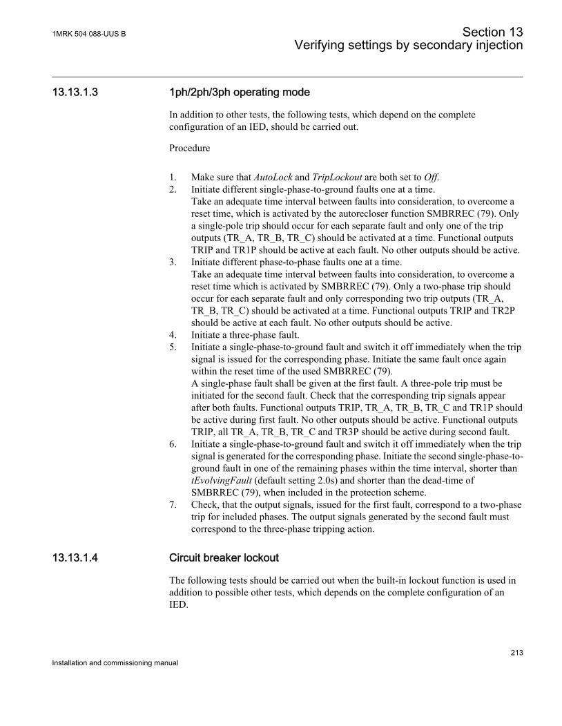
13.13.1.3 1ph/2ph/3ph operating mode
In addition to other tests, the following tests, which depend on the completeconfiguration of an IED, should be carried out.
Procedure
1. Make sure that AutoLock and TripLockout are both set to Off.2. Initiate different single-phase-to-ground faults one at a time.
Take an adequate time interval between faults into consideration, to overcome areset time, which is activated by the autorecloser function SMBRREC (79). Onlya single-pole trip should occur for each separate fault and only one of the tripoutputs (TR_A, TR_B, TR_C) should be activated at a time. Functional outputsTRIP and TR1P should be active at each fault. No other outputs should be active.
3. Initiate different phase-to-phase faults one at a time.Take an adequate time interval between faults into consideration, to overcome areset time which is activated by SMBRREC (79). Only a two-phase trip shouldoccur for each separate fault and only corresponding two trip outputs (TR_A,TR_B, TR_C) should be activated at a time. Functional outputs TRIP and TR2Pshould be active at each fault. No other outputs should be active.
4. Initiate a three-phase fault.5. Initiate a single-phase-to-ground fault and switch it off immediately when the trip
signal is issued for the corresponding phase. Initiate the same fault once againwithin the reset time of the used SMBRREC (79).A single-phase fault shall be given at the first fault. A three-pole trip must beinitiated for the second fault. Check that the corresponding trip signals appearafter both faults. Functional outputs TRIP, TR_A, TR_B, TR_C and TR1P shouldbe active during first fault. No other outputs should be active. Functional outputsTRIP, all TR_A, TR_B, TR_C and TR3P should be active during second fault.
6. Initiate a single-phase-to-ground fault and switch it off immediately when the tripsignal is generated for the corresponding phase. Initiate the second single-phase-to-ground fault in one of the remaining phases within the time interval, shorter thantEvolvingFault (default setting 2.0s) and shorter than the dead-time ofSMBRREC (79), when included in the protection scheme.
7. Check, that the output signals, issued for the first fault, correspond to a two-phasetrip for included phases. The output signals generated by the second fault mustcorrespond to the three-phase tripping action.
13.13.1.4 Circuit breaker lockout
The following tests should be carried out when the built-in lockout function is used inaddition to possible other tests, which depends on the complete configuration of anIED.
1MRK 504 088-UUS B Section 13Verifying settings by secondary injection
213Installation and commissioning manual
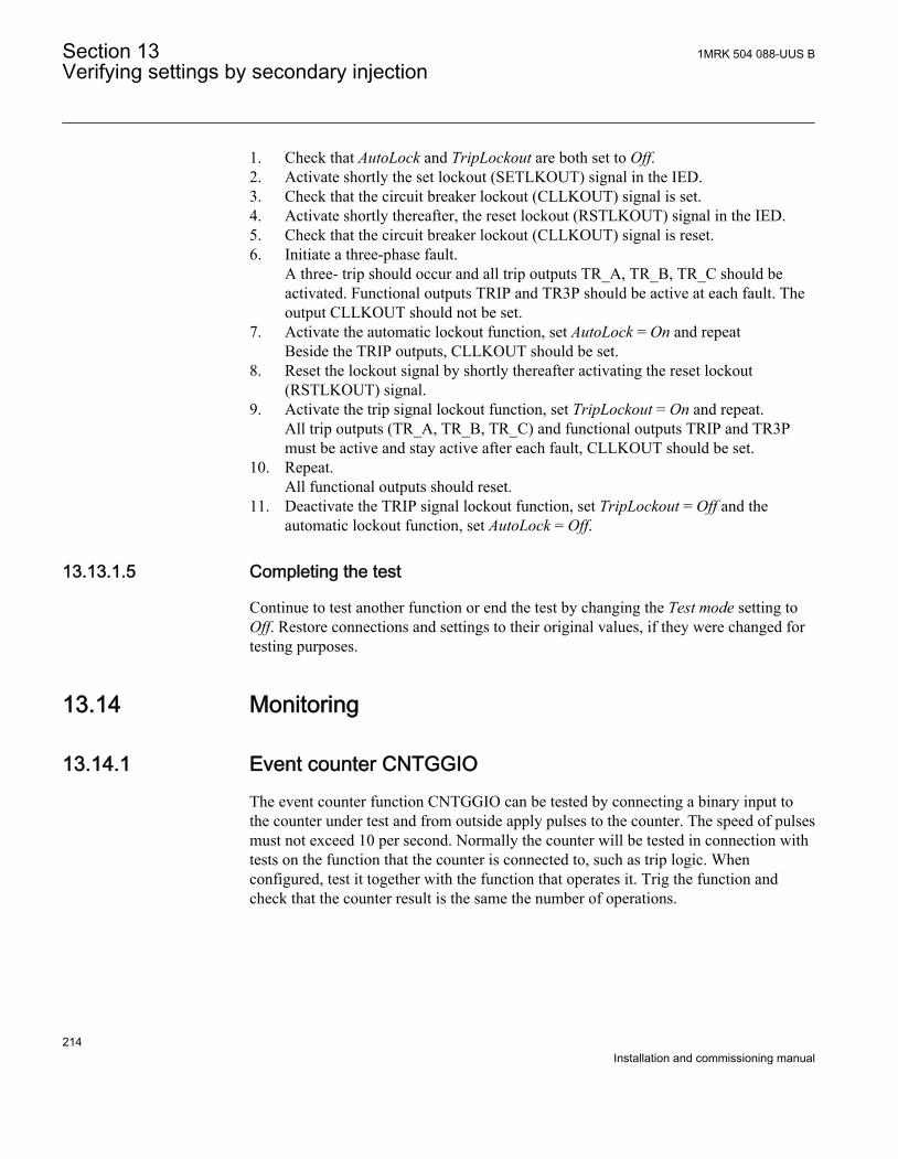
1. Check that AutoLock and TripLockout are both set to Off.2. Activate shortly the set lockout (SETLKOUT) signal in the IED.3. Check that the circuit breaker lockout (CLLKOUT) signal is set.4. Activate shortly thereafter, the reset lockout (RSTLKOUT) signal in the IED.5. Check that the circuit breaker lockout (CLLKOUT) signal is reset.6. Initiate a three-phase fault.
A three- trip should occur and all trip outputs TR_A, TR_B, TR_C should beactivated. Functional outputs TRIP and TR3P should be active at each fault. Theoutput CLLKOUT should not be set.
7. Activate the automatic lockout function, set AutoLock = On and repeatBeside the TRIP outputs, CLLKOUT should be set.
8. Reset the lockout signal by shortly thereafter activating the reset lockout(RSTLKOUT) signal.
9. Activate the trip signal lockout function, set TripLockout = On and repeat.All trip outputs (TR_A, TR_B, TR_C) and functional outputs TRIP and TR3Pmust be active and stay active after each fault, CLLKOUT should be set.
10. Repeat.All functional outputs should reset.
11. Deactivate the TRIP signal lockout function, set TripLockout = Off and theautomatic lockout function, set AutoLock = Off.
13.13.1.5 Completing the test
Continue to test another function or end the test by changing the Test mode setting toOff. Restore connections and settings to their original values, if they were changed fortesting purposes.
13.14 Monitoring
13.14.1 Event counter CNTGGIOThe event counter function CNTGGIO can be tested by connecting a binary input tothe counter under test and from outside apply pulses to the counter. The speed of pulsesmust not exceed 10 per second. Normally the counter will be tested in connection withtests on the function that the counter is connected to, such as trip logic. Whenconfigured, test it together with the function that operates it. Trig the function andcheck that the counter result is the same the number of operations.
Section 13 1MRK 504 088-UUS BVerifying settings by secondary injection
214Installation and commissioning manual
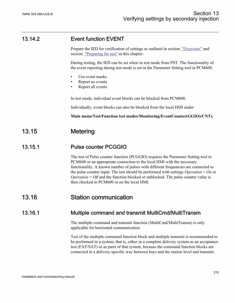
13.14.2 Event function EVENTPrepare the IED for verification of settings as outlined in section "Overview" andsection "Preparing for test" in this chapter.
During testing, the IED can be set when in test mode from PST. The functionality ofthe event reporting during test mode is set in the Parameter Setting tool in PCM600.
• Use event masks• Report no events• Report all events
In test mode, individual event blocks can be blocked from PCM600.
Individually, event blocks can also be blocked from the local HMI under
Main menu/Test/Function test modes/Monitoring/EventCounter(GGIO)/CNTx
13.15 Metering
13.15.1 Pulse counter PCGGIOThe test of Pulse counter function (PCGGIO) requires the Parameter Setting tool inPCM600 or an appropriate connection to the local HMI with the necessaryfunctionality. A known number of pulses with different frequencies are connected tothe pulse counter input. The test should be performed with settings Operation = On orOperation = Off and the function blocked or unblocked. The pulse counter value isthen checked in PCM600 or on the local HMI.
13.16 Station communication
13.16.1 Multiple command and transmit MultiCmd/MultiTransmThe multiple command and transmit function (MultiCmd/MultiTransm) is onlyapplicable for horizontal communication.
Test of the multiple command function block and multiple transmit is recommended tobe performed in a system, that is, either in a complete delivery system as an acceptancetest (FAT/SAT) or as parts of that system, because the command function blocks areconnected in a delivery-specific way between bays and the station level and transmit.
1MRK 504 088-UUS B Section 13Verifying settings by secondary injection
215Installation and commissioning manual
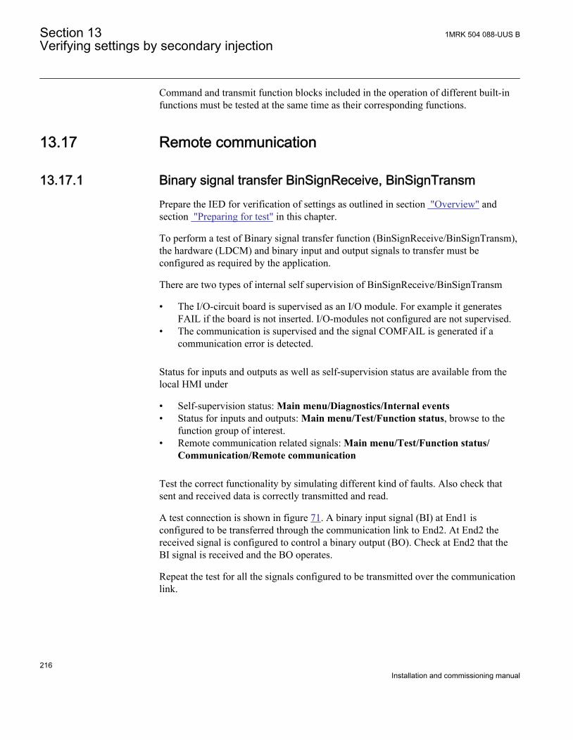
Command and transmit function blocks included in the operation of different built-infunctions must be tested at the same time as their corresponding functions.
13.17 Remote communication
13.17.1 Binary signal transfer BinSignReceive, BinSignTransmPrepare the IED for verification of settings as outlined in section "Overview" andsection "Preparing for test" in this chapter.
To perform a test of Binary signal transfer function (BinSignReceive/BinSignTransm),the hardware (LDCM) and binary input and output signals to transfer must beconfigured as required by the application.
There are two types of internal self supervision of BinSignReceive/BinSignTransm
• The I/O-circuit board is supervised as an I/O module. For example it generatesFAIL if the board is not inserted. I/O-modules not configured are not supervised.
• The communication is supervised and the signal COMFAIL is generated if acommunication error is detected.
Status for inputs and outputs as well as self-supervision status are available from thelocal HMI under
• Self-supervision status: Main menu/Diagnostics/Internal events• Status for inputs and outputs: Main menu/Test/Function status, browse to the
function group of interest.• Remote communication related signals: Main menu/Test/Function status/
Communication/Remote communication
Test the correct functionality by simulating different kind of faults. Also check thatsent and received data is correctly transmitted and read.
A test connection is shown in figure 71. A binary input signal (BI) at End1 isconfigured to be transferred through the communication link to End2. At End2 thereceived signal is configured to control a binary output (BO). Check at End2 that theBI signal is received and the BO operates.
Repeat the test for all the signals configured to be transmitted over the communicationlink.
Section 13 1MRK 504 088-UUS BVerifying settings by secondary injection
216Installation and commissioning manual
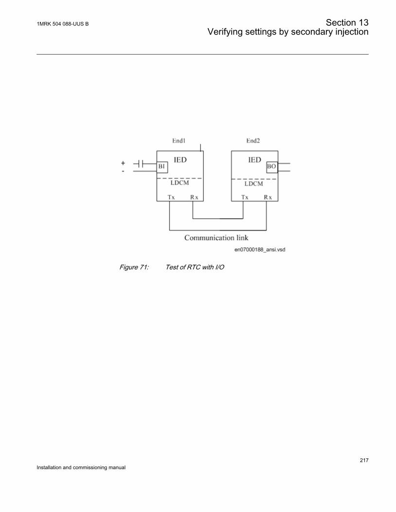
ANSI07000188 V1 EN
Figure 71: Test of RTC with I/O
1MRK 504 088-UUS B Section 13Verifying settings by secondary injection
217Installation and commissioning manual

218
Section 14 Primary injection testing
About this chapterThis chapter describes tests with primary current through the protected zone todetermine that connections and settings are correct.
14.1 Primary injection testing
Whenever it becomes necessary to work on primary equipment, it isessential that all the necessary switching, locking, grounding and safetyprocedures are observed and obeyed in a rigid and formalized manner.Operating and testing procedures should be strictly followed in order toavoid exposure to the substation equipment that has not been properly de-energized.
A test with primary current through the protected zone is usually a final check that thecurrent circuits are correctly connected to the IED protection scheme. It is important tohave an appropriate source, which is able to inject sufficient current in the primarycircuit in order to distinguish between noise and real injected current. Therefore it isrecommended that the injection current should be at least 10% of rated CT primarycurrent.
14.1.1 Voltage control VCTR
14.1.1.1 Load drop compensation function, LDC
The load drop compensation function can be tested directly with operational currents,that is, with the power transformer in service and loaded.
When the system is carrying load there will be a difference between the busbar voltage(VB) and the voltage at the load point (VL). This difference is load dependent and canbe compensated by the VCTR function.
1MRK 504 088-UUS B Section 14Primary injection testing
219Installation and commissioning manual
The load current is fed into the VCTR function where parameters corresponding to theline data for resistance and inductance are set. The voltage drop calculated by the LDCwill be proportional to the voltage drop in the system up to the load point.
In the IED this voltage will be subtracted from the measured busbar voltage (VB) andthe result, corresponding to the voltage at the load point (UL) will be presented to theVCTR function for the purposes of voltage regulation. This voltage will be lower (ifresitive or inductive load current is applied) than the Vset voltage and VCTR willincrease the voltage in order to achieve the correct system voltage at the load point.
Procedure
1. Confirm that the LDC function is set to On in the local HMI under Main menu/Settings/Setting group N/Control/TransformerVoltageControl(ATCC,90)/VCSx/VCPx/LDC/OperationLDC
2. Set (or confirm settings for) the line data (RL + j XL) to the load point in thelocal HMI under Main menu/Settings/Setting group N/Control/TransformerVoltageControl(ATCC,90)/VCSx/VCPx/LDC/RLine and XLine
3. Check the position of the tap changer.4. Read the bus and load voltage from the local HMI under Main menu/Control/
Commands/TransformerVoltageControl(ATCC,90)/VCSx/VCPx. Note thevalues and the difference. The voltage at the busbar will be the system voltagecorresponding to Vset. At load point it will be lower than the system voltage.
5. Set R and XL for the LDC to 0 (Zero).6. Check the bus and load voltage in the local HMI and confirm that both are higher
than the first readings. At load point it will be the system voltage and at thebusbar the system voltage increased with the line voltage drop. VCTR shall havealso operated during these setting changes.
14.1.1.2 Testing the LDC function
Procedure
1. Confirm the settings in the Parameter Setting tool for VSet and VDeadband2. Set Rline and Xline for the LDC to Zero.3. Manually operate the tap changer so that the voltage at the transformer (UB)
corresponds to the regulating value VSet.Check that neither the raise command nor the lower command are operating. Thiscan be confirmed by checking the signals from the configured binary outputs andthe event report on the local HMI. The test of the LDC should be carried out witha single current at one time from the main current transformers in L1 and L3 phase.
Section 14 1MRK 504 088-UUS BPrimary injection testing
220Installation and commissioning manual
3.1. When measuring the current from the L1 phase, the main CT in L3 phasemust have its secondary winding short circuited and the cables to the IEDdisconnected.
3.2. When measuring the current from the L3 phase, the main currenttransformer in L1 phase must have its secondary winding short-circuitedand the cables to the IED disconnected.
4. Modify the connections according to step a above.5. Increase slightly the setting VSet so that the RAISE output is on the verge of
activation (that is, just below the measured value for bus voltage).6. Set Rline and Xline to values for the maximum line impedance to the load point.
The RAISE output should activate when either Rline or Xline will be set to themaximum value. The operation can be checked at the corresponding binaryoutput and in the event report. If the RAISE output does not activate reset bothRline and Xline to Zero and set VSet to a little lower value until the lower circuitis on the verge of operation.If the LOWER output activates when either Rline or Xline have a high setting thecurrent circuits of the L1 phase are incorrect and must be reversed. Incorrectcurrent polarity may be an issue with physical wiring or the current directionconvention selected for the CT analogue input as part of the setting in theParameter Setting tool. The operation can be checked at the corresponding binaryoutput and in the event report.
7. Restore the original connections at the CT in phase L1.8. Modify the connections according to step b.9. Increase slightly the setting VSet so that the RAISE output is on the verge of
activation (that is, just below the measured value for bus voltage (UB)).10. Set Rline and Xline to values for the maximum line impedance to the load point.
The RAISE output should activate when either Rline or Xline will be set to themaximum value. The operation can be checked at the corresponding binaryoutput and in the event report. If the RAISE output does not activate reset bothRline and Xline to Zero and set VSet to a little lower value until the lower circuitis on the verge of operation.If the LOWER output activates when either Rline or Xline have a high setting thecurrent circuits of the L1 phase are incorrect and must be reversed. Incorrectcurrent polarity may be an issue with physical wiring or the current directionconvention selected for the CT analogue input as part of the setting in theParameter Setting tool. The operation can be checked at the corresponding binaryoutput and in the event report.
11. Retain the settings for Rline and Xline to values as the maximum line impedanceto the load point.
12. Decrease slowly the setting of VSet until the lower circuit is on the verge ofoperation (that is, just above the calculated value for load (VL)).
13. Reduce the setting for XLine to Zero so that the lower circuit operates.
1MRK 504 088-UUS B Section 14Primary injection testing
221Installation and commissioning manual
If the operation of Raise and Lower is inverted (Lower instead of Raise and Raiseinstead Lower) the current connections have to be reversed in the same way as forthe tests of the Raise component of the voltage regulation with LDC.
14. Modify the CT connections according to (b) and undertake the same test for the“Lower” of the tap changer with LDC (repeating steps 11 to 13).
15. Restore settings for VSet, RLine and XLine to normal in service values.16. Restore the original connections at the CT in phase L3.17. After these tests, the single mode voltage control function in the IED can be taken
in to service.
14.1.1.3 Voltage control of Parallel Transformers
Parallel transformer voltage control can be achieved through two methods, MinimumCirculating Current (MCC – refer to section "Minimum Circulating Current (MCC)method") and Master Follower (MF – refer to section "Master Follower (MF) method").
Parallel transformer control can be achieved via:
• a single IED with application configuration for the necessary data transfer, for upto four transformers, or
• multiple IEDs (with up to 8 VCTR functions in total) communicating via Goosemessages on station bus IEC 61850-8-1
The parallel control functions can be tested directly with operational currents, that is,with the power transformer in service and loaded.
14.1.1.4 Minimum Circulating Current (MCC) method
The method is used when two or more transformers are to be parallel controlled. Amaximum of four transformers can be controlled simultaneously.
To use this method, each transformer protection IED must be connected to the stationcommunication bus, to exchange data. The following test procedure will assume thatthe necessary pre-configuration in the Parameter Setting tool and the Signal Matrix toolhas occurred to enable data exchange between IEDs or between instances of voltagecontrol in the same IED.
Procedure
1. Confirm or set the correct VSet and VDeadband in service values.2. Set the correct overcurrent blocking level (Iblock) in service value.3. Set the circulating current blocking (OperCCBlock) to Enabled, and the correct
settings for circulating current limit (CircCurLimit) and time delay for circulatingcurrent blocking (tCircCurr) in service value.
Section 14 1MRK 504 088-UUS BPrimary injection testing
222Installation and commissioning manual

4. Set Rline and Xline to Zero.5. For parallel operation, it is also recommended that settings are confirmed for
parallel group membership, governed by the TnRXOP setting in the ParameterSetting tool under Main menu/Settings/Setting group N/Control/TransformerVoltageControl(ATCC,90)/VCPx/ParCtrlIn the Parameter Setting, the general parallel arrangement of transformers aredefined by setting TnRXOP to On or Off.The following rules are applicable on thesettings T1RXOP - T4RXOP.If IED T1 and T2 are connected,• T1RXOP shall be set to Enabled in instance 2 of TR8ATCC (90), and• T2RXOP shall be set to Enabled in instance 1 of TR8ATCC (90).
If T1 - T3 are available• T1RXOP and T2RXOP shall be set to Enabled in instance 3 of TR8ATCC (90)• T2RXOP and T3RXOP shall be set to Enabled in instance 1 of TR8ATCC
(90) and so on.
The parameter corresponding to the own IED must not be set.T1RXOP should thus not be set in IED T1, T2RXOP not in IEDT2, and so on.
6. Set the parallel operation (OperationPAR) to Off.7. Set the control mode, for each transformer in the parallel control group, to
Manual in the local HMI for that IED.8. Undertaking switching operations to connect all transformers to the same bus on
the secondary side.9. Manually execute RAISE commands from the local HMI to step up the tap
changer for transformer T1, two steps above the setting for the other transformersin the parallel group.
10. Change the setting of VSet in each of the remaining transformers to correspond tothe manually set busbar voltage being measured by T1, which can be located onthe local HMI under Main menu/Control/Command/TansformerVoltageControl(ATCC,90)/VCSx/VCPx
11. Set in all the parallel connected transformers the parameter OperationPAR to CC.12. On the lcoal HMI, set the control mode to Automatic for all transformers.13. For transformer T1 adjust the parameter Comp in the local HMI under Main
menu/Settings/Setting group N/Control/TransformerVoltageControl(ATCC,90)/VCPx/ParCtrl/Comp so that the LOWER output is activated due tocirculating current, based on guidelines below.
Comp is a setting for circulating current Compensating Factor,and it is effectively a multiplier value to change the sensitivity ofthe voltage regulation function to measured values of circulating
1MRK 504 088-UUS B Section 14Primary injection testing
223Installation and commissioning manual
current. A nominal value of 200 for Comp should be appropriateto achieve sensitive voltage regulation. Values less may lead to anormal state where tap changers for parallel transformers are wellout of step, and values significantly higher will cause oversensitivity in the voltage control function and tap changer huntingbehavior.It is an important outcome of the testing process that thecompensating factor is checked for each transformer to ensuresensitive but stable operation for circulating currents.Example of Comp behaviorIf there are three transformers connected in parallel, and the tapchanger of transformer T1 lies two steps over the tap changer ofT2 and T3, the circulating current detected by the VCTR for T1will be the sum (with opposite sign) of the current measured at T2and T3. The currents measured at T2 and T3 will ideally be aboutthe same values.If the voltage is close to the upper limit of the VDeadband, the tapchanger of T1 will try to decrease the controlled voltage. In theopposite case, that is, the voltage is close to the lower limit ofVDeadband, the tap changer at T1 will not try to decrease thecontrolled voltage.The tap changer for T2 and T3 will not operate due to the fact thatthe detected circulating current will be half of the current detectedat T1.The setting of the parameter Comp then might need to beincreased a little.At least one tap changer step difference between the differenttransformers should be allowed in order to avoid the tap changersto operate too often. If the allowed difference is for example twosteps, the tap changer shall be stepped up three steps when settingthe parameter Comp. This applies to all the VCTR in the same group.
14. The setting of the parameter Comp at T2 and T3 will be carried out in the samemanner as at T1. According to the described procedure when the tap changer ofone transformer lies two steps above the others, it shall automatically step down.When there are only two transformers in the group either shall one step down orthe other step up depending on the voltage level at the VCTR.
15. Before placing the VCTR into service, confirm the correct settings of VSet,VDeadband, the blocking settings for overcurrent, undervoltage and highcirculating currents, and the compensating parameters Rline and Xline.
Section 14 1MRK 504 088-UUS BPrimary injection testing
224Installation and commissioning manual
Also confirm the settings in the Signal Matrix for binary RAISE and LOWERoutputs in conjunction with the basic CET configuration for Goose messagesbetween parallel transformer control functions.
16. Ensure that the automatic control mode is set for each transformer from the IEDand that OperationPAR is set to CC.
14.1.1.5 Master Follower (MF) method
Master follower method requires a Master to be nominated in a parallel group, that isresponsible for measuring secondary bus voltage, and executing commands to raise andlower tap changers, that are repeated by Follower transformers in the group.
Procedure
1. Confirm or set VSet and VDeadband to the correct in the service values.2. Set the correct overcurrent blocking level (IBlock) in the service value.3. Set Rline and Xline to Zero.4. Confirm the setting of MFMode as Follow Tap or Follow Cmd. If this setting is
Follow Tap, all Follower transformers shall match the actual tap setting of theMaster, while Follow Cmd requires that Follower transformers follow the RAISEand LOWER commands executed by the Master in the local HMI under Mainmenu/Settings/General settings/Control/TransformerVoltageControl(ATCC,90)/VCPx/MFMode
Note that the maximum difference in tap positions for paralleltransformers will be determined by the setting in the ParameterSetting tool under Main menu/Settings/Setting group N/Control/TransformerVoltageControl(ATCC,90)/VCPx/ParCtrl/MFPosDiffLim and that tap differences exceeding thatsetting can produce system alarms or blocking of the VCTR.
5. For parallel operation, it is also recommended to confirm settings for parallelgroup membership, of the setting TnRXOP in the Parameter Setting tool underMain menu/Settings/Setting group N/Control/TransformerVoltageControl(ATCC,90)/VCPx/ParCtrlIn the Parameter Setting tool, the general parallel arrangement of transformers aredefined by setting TnRXOP to On or Off. The following rules are applicable onthe settings T1RXOP - T4RXOP.If terminal T1 and T2 are connected,• T1RXOP shall be set to On in instance 2 of TR8ATCC, and• T2RXOP shall be set to On in instance 1 of TR8ATCC.
If T1 - T3 are available,
1MRK 504 088-UUS B Section 14Primary injection testing
225Installation and commissioning manual
• T1RXOP and T2RXOP shall be set to On in instance 3 of TR8ATCC, and• T2RXOP and T3RXOP shall be set to On in instance 1 of TR8ATCC, and so
on.
The parameter corresponding to the own IED must not be set.T1RXOP should thus not be set in IED T1, T2RXOP not in IEDT2, and so on.
6. Set the parallel operation (OperationPAR) to Off for each transformer.7. On the local HMI, set the control mode to Manual for each transformer in the
parallel control group.8. Undertaking switching operations to connect all transformers to the same bus on
the secondary side.9. Set OperationPAR to MF for all transformers in the parallel group and confirm
that the lowest transformer number in the group is set as Master. Allow the issueof RAISE and LOWER commands so that the secondary bus voltage stabilizes atVSet.
10. Change VSet in the Master transformer T1 so that it is 1% below the measuredbus voltage value on the local HMI and set all transformers to automatic controlmode using the local HMI.
11. The Master in the parallel group will issue a LOWER command after time delayt1, which will also be repeated by the Follower transformers in the group.
12. Return VSet for T1 to its normal in the service value.13. Using the local HMI, set Transformer 2 to Master of the parallel group and T1 to
Follower (in that order) and repeat steps 9 to 11. Undertake this same test bysetting each Transformer in turn to Master.
14. Note that voltage regulation will be mutually blocked if no transformer is set toMaster in the parallel group. To confirm this function, set T1 as Master in theparallel group and allow automatic voltage regulation to occur in a way that themeasured bus voltage is stable around VSet. Without allocating a new Master, setT1 to Follower and note the Automatic block state on the local HMI for allparallel transformers.
15. Restore T1 to Master of the parallel transformer group and ensure that controlmode for each transformer is Automatic, OperationPAR is set to MF and settingsfor VSet are restored to normal in the service values.
14.1.1.6 Completing the test
Continue to test another function or end the test by changing the Test mode setting toOff. Restore connections and settings to their original values, if they were changed fortesting purposes.
Section 14 1MRK 504 088-UUS BPrimary injection testing
226Installation and commissioning manual
Section 15 Commissioning and maintenance of thefault clearing system
About this chapterThis chapter discusses maintenance tests and other periodic maintenance measures.
15.1 Installation and commissioning
The protection IED is in an on-guard situation where the IED can be inactive forseveral years and then suddenly be required to operate within fractions of a second.This means that maintenance testing with certain time intervals should be performed todetect failures of the protection IED or the surrounding circuits. This is a complementto the advanced self supervision in the modern protection IED.
IEDs are not expected to deteriorate with usage but extreme conditions, such asmechanical shocks, AC or DC transients, high ambient temperatures, and high airhumidity always have a certain likelihood of causing damages.
Delivered equipment undergoes extensive testing and quality control in the ABBmanufacturing program. All types of IEDs and their integral components have beensubject to extensive laboratory testing during the development and design work. Priorto series production of a specific IED, it is type tested according to national andinternational standards. Each individual IED in normal production is individuallytested and calibrated before delivery.
Protection IEDs installed in an apparatus cubicle shall be checked in various waysbefore delivery. Insulation test (to check for bad wiring) and complete testing of allequipment with injection of currents and voltages is performed.
During the design of the station, certain steps shall be taken to limit the risk of failures,for example, all IED coils are connected to negative potential to ground to preventcontact corrosion due to electrolyte.
Certain circuits are continuously supervised to improve their availability. Examples ofsuch supervisions are:
1MRK 504 088-UUS B Section 15Commissioning and maintenance of the fault clearing system
227Installation and commissioning manual
• Trip circuit supervision• Protection DC supply supervision• DC system ground fault supervision• Busbar protection CT-circuit supervision
Protection IEDs shall be encapsulated according to environment requirements. Intropical climates, cubicles are provided with glass-door and ventilation louvres.Heaters for anti-condensation, often thermostatically controlled, are provided. Cubiclepower-loss is limited not to exceed protection IED temperature limits, which is 55°C .
15.2 Commissioning tests
During commissioning all protection functions shall be verified with the setting valuesused at each plant. The commissioning tests must include verification of all circuits byhighlighting the circuit diagrams and the configuration diagrams for the used functions.
Further, the settings for protection functions are tested and recorded carefully asoutlined for the future periodic maintenance tests.
The final testing includes primary verification of all directional functions where loadcurrents is checked on the local HMI and in PCM600.. The magnitudes and angles ofall currents and voltages should be checked and the symmetry verified.
Directional functions have information about the measured direction and, for example,measured impedance. These values must be checked and verified as correct with theexport or import of power available.
Finally, final trip tests must be performed. This involves activation of protectionfunctions or tripping outputs with the circuit breaker closed and the tripping of thebreaker verified. When several breakers are involved, each breaker must be checkedindividually and it must be verified that the other involved breakers are not tripped atthe same time.
15.3 Periodic maintenance tests
The periodicity of all tests depends on several factors, for example the importance ofthe installation, environment conditions, simple or complex equipment, static orelectromechanical IEDs, and so on.
The normal maintenance practices of the user should be followed. However ABBproposal is to test:
Section 15 1MRK 504 088-UUS BCommissioning and maintenance of the fault clearing system
228Installation and commissioning manual
Every second to third year
• Visual inspection of all equipment.• Removal of dust on ventilation louvres and IEDs if necessary.• Periodic maintenance test for protection IEDs of object where no redundant
protections are provided.
Every four to six years
• Periodic maintenance test for protection IEDs of objects with redundant protectionsystem.
First maintenance test should always be carried out after the first halfyear of service.
When protection IEDs are combined with built-in control, the testinterval can be increased drastically, up to for instance 15 years,because the IED continuously reads service values, operates thebreakers, and so on.
15.3.1 Visual inspectionPrior to testing, the protection IEDs should be inspected to detect any visible damagethat may have occurred (for example, dirt or moisture deposits, overheating). Shouldburned contacts be observed when inspecting the IEDs, a diamond file or an extremelyfine file can be used to polish the contacts. Emery cloth or similar products must not beused as insulating grains of abrasive may be deposited on the contact surfaces andcause failure.
Make sure that all IEDs are equipped with covers.
15.3.2 Maintenance testsTo be made after the first half year of service, then with the cycle as proposed aboveand after any suspected maloperation or change of the IED setting.
Testing of protection IEDs shall preferably be made with the primary circuit de-energized. The IED cannot protect the circuit during testing. Trained personnel maytest one IED at a time on live circuits where redundant protection is installed and de-energization of the primary circuit is not allowed.
1MRK 504 088-UUS B Section 15Commissioning and maintenance of the fault clearing system
229Installation and commissioning manual
ABB protection IEDs are preferably tested by aid of components from theCOMBITEST testing system or FT test systems described in information B03-9510 E.Main components are RTXP 8/18/24 test switch located to the left in each protectionIED and RTXH 8/18/24 test handle, which is inserted in test switch at secondarytesting. All necessary operations such as opening of trip circuits, short-circuiting ofcurrent circuits and opening of voltage circuits are automatically performed in the rightorder to allow for simple and safe secondary testing even with the object in service.
Important components of FT test system are FT1, FTx, FT19, FT19RS, FR19RXswitches and assemblies as well as FT-1 test plug.
15.3.2.1 Preparation
Before starting maintenance testing, the test engineers should scrutinize applicablecircuit diagrams and have the following documentation available:
• Test instructions for protection IEDs to be tested• Test records from previous commissioning and maintenance tests• List of valid settings• Blank test records to fill in measured values
15.3.2.2 Recording
It is of utmost importance to carefully record the test results. Special test sheetscovering the frequency of test, date of test and achieved test values should be used.IED setting list and protocols from previous tests should be available and all resultsshould be compared for differences. At component failures, spare equipment is usedand set to the requested value. A note of the exchange is made and the new measuredvalues are recorded. Test records for several years of testing should be stored in acommon file for a station, or a part of a station, to give a simple overview of the periodof testing and achieved test values. These test records are valuable when analysis ofservice disturbances shall be done.
15.3.2.3 Secondary injection
The periodic maintenance test is done by secondary injection from a portable test set.Each protection shall be tested according to the secondary injection test information forthe specific protection IED. Only the setting values adopted shall be checked for eachprotection function. If the discrepancy between obtained value and requested set valueis too big the setting should be adjusted, the new value recorded and a note should bemade in the test record.
Section 15 1MRK 504 088-UUS BCommissioning and maintenance of the fault clearing system
230Installation and commissioning manual
15.3.2.4 Alarm test
When inserting the test handle of RTXP or using FT plugs, the alarm and eventsignalling is normally blocked. This is done in the IED by setting the event reporting toOff during the test. This can be done when the test handle is inserted or the IED is setto test mode from the local HMI. At the end of the secondary injection test it should bechecked that the event and alarm signalling is correct by activating the events andperforming some selected tests.
15.3.2.5 Self supervision check
Once secondary testing has been completed, it should be checked that no self-supervision signals are activated continuously or sporadically. Especially check thetime synchronization system, GPS or other, and communication signals, both stationcommunication (61850/SPA/LON, and so on) and remote communication, forexample, the line differential communication system.
15.3.2.6 Trip circuit check
When the protection IED undergoes an operational check, a tripping pulse is normallyobtained on one or more of the output contacts and preferably on the test switch. Thehealthy circuit is of utmost importance for the protection operation. If the circuit is notprovided with a continuous trip-circuit supervision, it is possible to check that circuit isreally closed when the test-plug handle has been removed by using a high-ohmicvoltmeter and measuring between the plus and the trip output on the panel. Themeasurement is then done through the tripping magnet of the circuit breaker andtherefore the complete tripping circuit is checked.
Note, that the breaker must be closed.
Please observe that the test system does not have its built-in securityduring this test. If the instrument should be set on Amp instead ofVolts, the circuit breaker naturally is tripped, therefore, greatest care isnecessary.
Trip circuit from trip IEDs to circuit breaker is often supervised by trip-circuitsupervision IED. It can then be checked that a circuit is healthy by opening trippingoutput terminals in the cubicle. When the terminal is opened, an alarm shall beachieved on the signal system after a delay of some seconds.
1MRK 504 088-UUS B Section 15Commissioning and maintenance of the fault clearing system
231Installation and commissioning manual
However, remember to close the circuit directly after the test andtighten the terminal carefully!
15.3.2.7 Measurement of service currents
After a maintenance test it is recommended to measure the service currents and servicevoltages recorded by the protection IED. The service values are checked on the localHMI or in PCM600. Ensure that the correct values and angles between voltages andcurrents are recorded. Also check the direction of directional functions such asDistance and directional overcurrent functions.
For transformer differential protection, the achieved differential current value isdependent on the tap changer position and can vary between less than 1% up toperhaps 10% of rated current. For line differential functions, the capacitive chargingcurrents can normally be recorded as a differential current.
The zero-sequence current to ground-fault protection IEDs should be measured. Thecurrent amounts normally very small but normally it is possible to see if the currentcircuit is "alive".
The neutral-point voltage to an ground-fault IED is checked. The voltage is normally0.1 to 1V secondary. However, voltage can be considerably higher due to harmonics.Normally a CVT secondary can have around 2.5 - 3% third-harmonic voltage.
15.3.2.8 Restoring
Maintenance is very important to improve the availability of the protection system bydetecting failures before the protection is required to operate. There is however littlepoint in testing healthy equipment and then putting it back into service with an openterminal, with a removed fuse or open miniature circuit breaker with an openconnection, wrong setting, and so on.
Thus a list should be prepared of all items disturbed during test so that all can be putback into service quickly and without overlooking something. It should be put backinto service item by item and signed by the responsible engineer.
Section 15 1MRK 504 088-UUS BCommissioning and maintenance of the fault clearing system
232Installation and commissioning manual
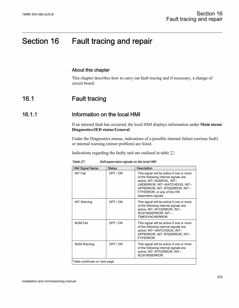
Section 16 Fault tracing and repair
About this chapterThis chapter describes how to carry out fault tracing and if necessary, a change ofcircuit board.
16.1 Fault tracing
16.1.1 Information on the local HMIIf an internal fault has occurred, the local HMI displays information under Main menu/Diagnostics/IED status/General
Under the Diagnostics menus, indications of a possible internal failure (serious fault)or internal warning (minor problem) are listed.
Indications regarding the faulty unit are outlined in table 27.
Table 27: Self-supervision signals on the local HMI
HMI Signal Name: Status DescriptionINT Fail OFF / ON This signal will be active if one or more
of the following internal signals areactive; INT--NUMFAIL, INT--LMDERROR, INT--WATCHDOG, INT--APPERROR, INT--RTEERROR, INT--FTFERROR, or any of the HWdependent signals
INT Warning OFF / ON This signal will be active if one or moreof the following internal signals areactive; INT--RTCERROR, INT--IEC61850ERROR, INT--TIMESYNCHERROR
NUM Fail OFF / ON This signal will be active if one or moreof the following internal signals areactive; INT--WATCHDOG, INT--APPERROR, INT--RTEERROR, INT--FTFERROR
NUM Warning OFF / ON This signal will be active if one or moreof the following internal signals areactive; INT--RTCERROR, INT--IEC61850ERROR
Table continues on next page
1MRK 504 088-UUS B Section 16Fault tracing and repair
233Installation and commissioning manual
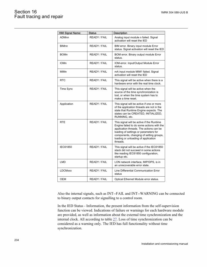
HMI Signal Name: Status DescriptionADMnn READY / FAIL Analog input module n failed. Signal
activation will reset the IED
BIMnn READY / FAIL BIM error. Binary input module Errorstatus. Signal activation will reset the IED
BOMn READY / FAIL BOM error. Binary output module Errorstatus.
IOMn READY / FAIL IOM-error. Input/Output Module Errorstatus.
MIMn READY / FAIL mA input module MIM1 failed. Signalactivation will reset the IED
RTC READY / FAIL This signal will be active when there is ahardware error with the real time clock.
Time Sync READY / FAIL This signal will be active when thesource of the time synchronization islost, or when the time system has tomake a time reset.
Application READY / FAIL This signal will be active if one or moreof the application threads are not in thestate that Runtime Engine expects. Thestates can be CREATED, INITIALIZED,RUNNING, etc.
RTE READY / FAIL This signal will be active if the RuntimeEngine failed to do some actions with theapplication threads. The actions can beloading of settings or parameters forcomponents, changing of setting groups,loading or unloading of applicationthreads.
IEC61850 READY / FAIL This signal will be active if the IEC61850stack did not succeed in some actionslike reading IEC61850 configuration,startup etc.
LMD READY / FAIL LON network interface, MIP/DPS, is inan unrecoverable error state.
LDCMxxx READY / FAIL Line Differential Communication Errorstatus
OEM READY / FAIL Optical Ethernet Module error status.
Also the internal signals, such as INT--FAIL and INT--WARNING can be connectedto binary output contacts for signalling to a control room.
In the IED Status - Information, the present information from the self-supervisionfunction can be viewed. Indications of failure or warnings for each hardware moduleare provided, as well as information about the external time synchronization and theinternal clock. All according to table 27. Loss of time synchronization can beconsidered as a warning only. The IED has full functionality without timesynchronization.
Section 16 1MRK 504 088-UUS BFault tracing and repair
234Installation and commissioning manual
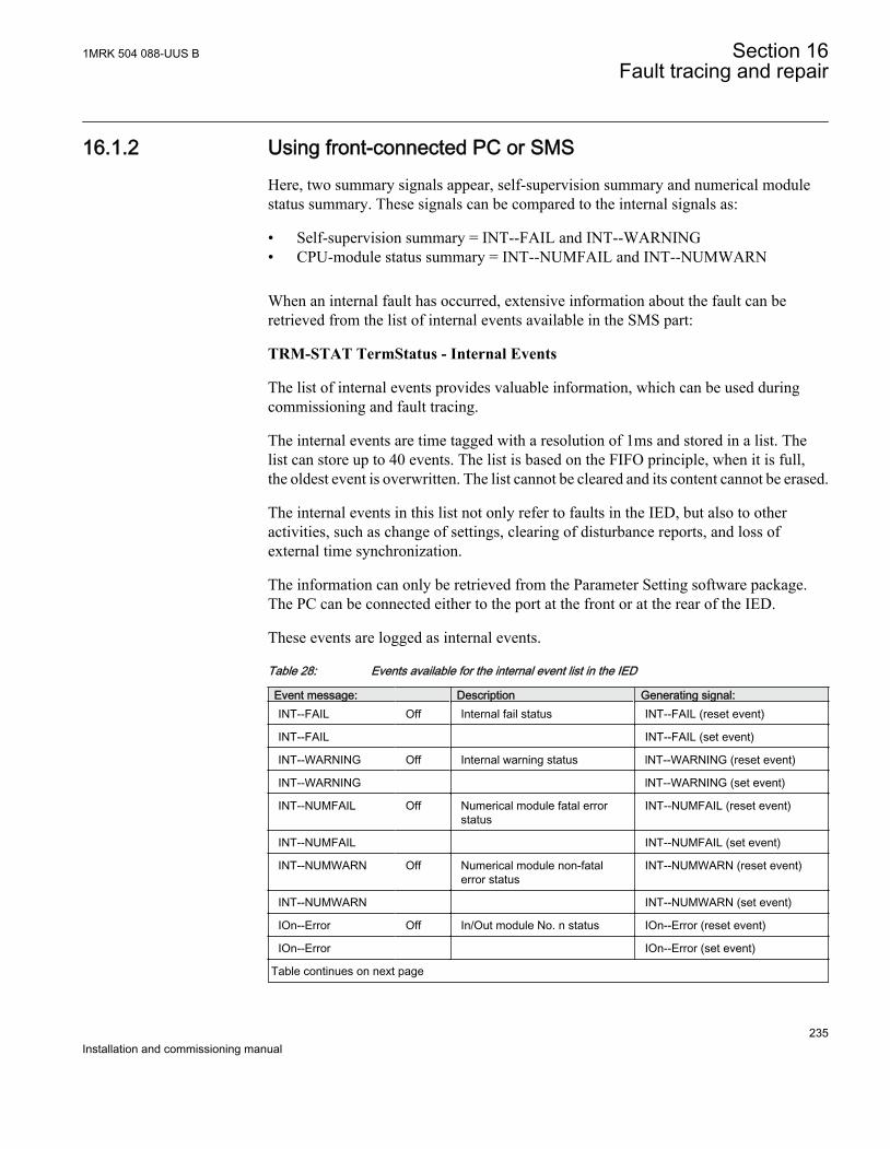
16.1.2 Using front-connected PC or SMSHere, two summary signals appear, self-supervision summary and numerical modulestatus summary. These signals can be compared to the internal signals as:
• Self-supervision summary = INT--FAIL and INT--WARNING• CPU-module status summary = INT--NUMFAIL and INT--NUMWARN
When an internal fault has occurred, extensive information about the fault can beretrieved from the list of internal events available in the SMS part:
TRM-STAT TermStatus - Internal Events
The list of internal events provides valuable information, which can be used duringcommissioning and fault tracing.
The internal events are time tagged with a resolution of 1ms and stored in a list. Thelist can store up to 40 events. The list is based on the FIFO principle, when it is full,the oldest event is overwritten. The list cannot be cleared and its content cannot be erased.
The internal events in this list not only refer to faults in the IED, but also to otheractivities, such as change of settings, clearing of disturbance reports, and loss ofexternal time synchronization.
The information can only be retrieved from the Parameter Setting software package.The PC can be connected either to the port at the front or at the rear of the IED.
These events are logged as internal events.
Table 28: Events available for the internal event list in the IED
Event message: Description Generating signal:INT--FAIL Off Internal fail status INT--FAIL (reset event)
INT--FAIL INT--FAIL (set event)
INT--WARNING Off Internal warning status lNT--WARNING (reset event)
INT--WARNING lNT--WARNING (set event)
INT--NUMFAIL Off Numerical module fatal errorstatus
INT--NUMFAIL (reset event)
INT--NUMFAIL INT--NUMFAIL (set event)
INT--NUMWARN Off Numerical module non-fatalerror status
INT--NUMWARN (reset event)
INT--NUMWARN INT--NUMWARN (set event)
IOn--Error Off In/Out module No. n status IOn--Error (reset event)
IOn--Error IOn--Error (set event)
Table continues on next page
1MRK 504 088-UUS B Section 16Fault tracing and repair
235Installation and commissioning manual
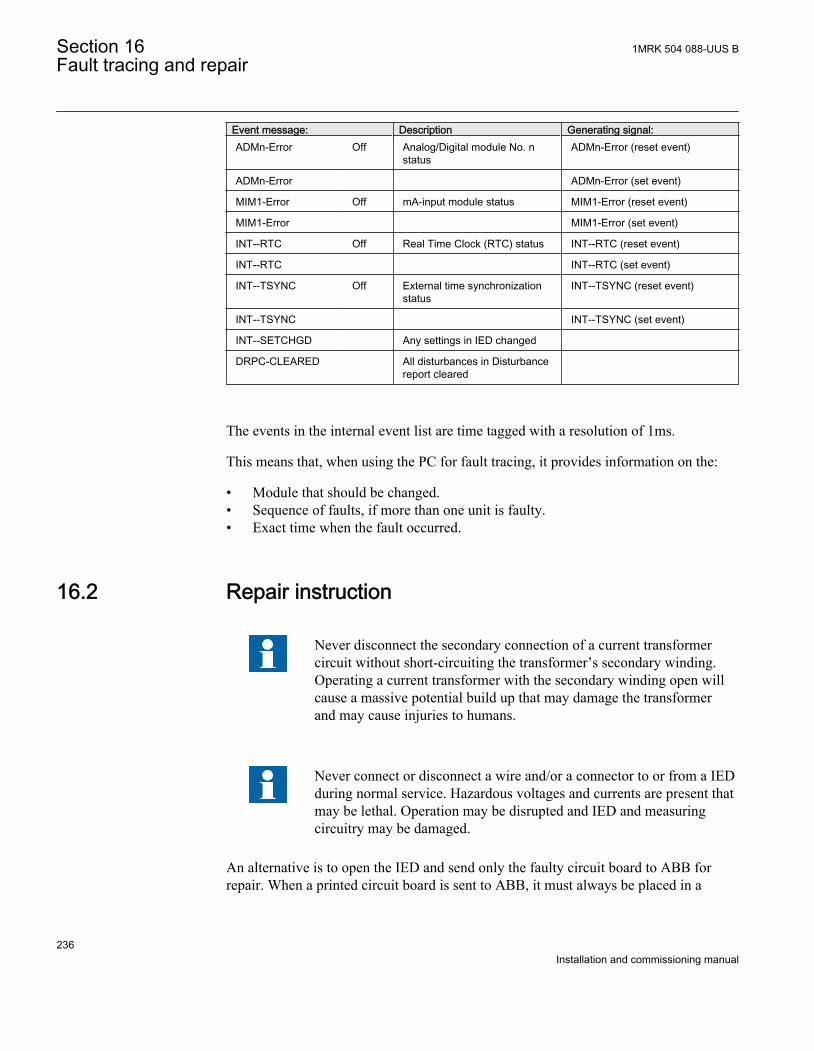
Event message: Description Generating signal:ADMn-Error Off Analog/Digital module No. n
statusADMn-Error (reset event)
ADMn-Error ADMn-Error (set event)
MIM1-Error Off mA-input module status MIM1-Error (reset event)
MIM1-Error MIM1-Error (set event)
INT--RTC Off Real Time Clock (RTC) status INT--RTC (reset event)
INT--RTC INT--RTC (set event)
INT--TSYNC Off External time synchronizationstatus
INT--TSYNC (reset event)
INT--TSYNC INT--TSYNC (set event)
INT--SETCHGD Any settings in IED changed
DRPC-CLEARED All disturbances in Disturbancereport cleared
The events in the internal event list are time tagged with a resolution of 1ms.
This means that, when using the PC for fault tracing, it provides information on the:
• Module that should be changed.• Sequence of faults, if more than one unit is faulty.• Exact time when the fault occurred.
16.2 Repair instruction
Never disconnect the secondary connection of a current transformercircuit without short-circuiting the transformer’s secondary winding.Operating a current transformer with the secondary winding open willcause a massive potential build up that may damage the transformerand may cause injuries to humans.
Never connect or disconnect a wire and/or a connector to or from a IEDduring normal service. Hazardous voltages and currents are present thatmay be lethal. Operation may be disrupted and IED and measuringcircuitry may be damaged.
An alternative is to open the IED and send only the faulty circuit board to ABB forrepair. When a printed circuit board is sent to ABB, it must always be placed in a
Section 16 1MRK 504 088-UUS BFault tracing and repair
236Installation and commissioning manual
metallic, ESD-proof, protection bag. The user can also purchase separate replacementmodules.
Strictly follow the company and country safety regulations.
Most electronic components are sensitive to electrostatic discharge and latent damagemay occur. Please observe usual procedures for handling electronics and also use anESD wrist strap. A semi-conducting layer must be placed on the workbench andconnected to ground.
Disassemble and reassemble the IED accordingly:
1. Switch off the dc supply.2. Short-circuit the current transformers and disconnect all current and voltage
connections from the IED.3. Disconnect all signal wires by removing the female connectors.4. Disconnect the optical fibers.5. Unscrew the main back plate of the IED.6. If the transformer module is to be changed:
• Remove the IED from the panel if necessary.• Remove the rear plate of the IED.• Remove the front plate.• Remove the screws of the transformer input module, both front and rear.
7. Pull out the faulty module.8. Check that the new module has a correct identity number.9. Check that the springs on the card rail are connected to the corresponding metallic
area on the circuit board when the new module is inserted.10. Reassemble the IED.
If the IED has been calibrated with the system inputs, the calibration procedure mustbe performed again to maintain the total system accuracy.
16.3 Repair support
If an IED needs to be repaired, the whole IED must be removed and sent to an ABBLogistic Center. Please contact the local ABB representative to get more details.
1MRK 504 088-UUS B Section 16Fault tracing and repair
237Installation and commissioning manual
16.4 Maintenance
The IED is self-supervised. No special maintenance is required.
Instructions from the power network company and other maintenance directives validfor maintenance of the power system must be followed.
Section 16 1MRK 504 088-UUS BFault tracing and repair
238Installation and commissioning manual
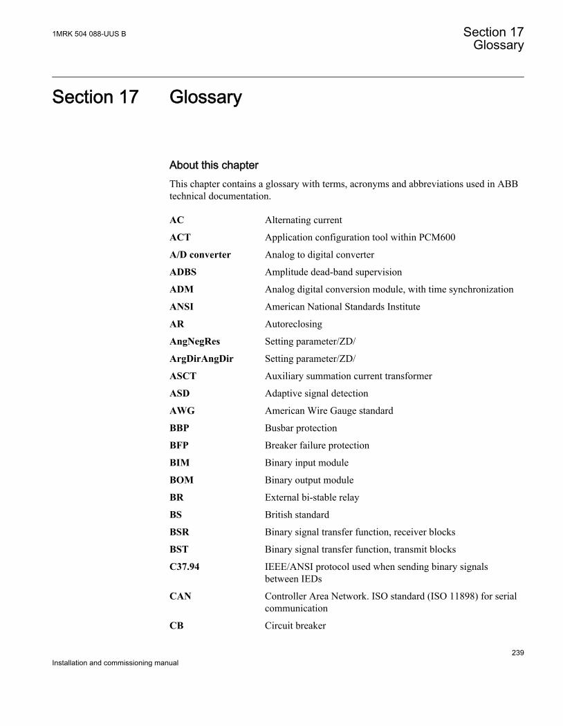
Section 17 Glossary
About this chapterThis chapter contains a glossary with terms, acronyms and abbreviations used in ABBtechnical documentation.
AC Alternating current
ACT Application configuration tool within PCM600
A/D converter Analog to digital converter
ADBS Amplitude dead-band supervision
ADM Analog digital conversion module, with time synchronization
ANSI American National Standards Institute
AR Autoreclosing
AngNegRes Setting parameter/ZD/
ArgDirAngDir Setting parameter/ZD/
ASCT Auxiliary summation current transformer
ASD Adaptive signal detection
AWG American Wire Gauge standard
BBP Busbar protection
BFP Breaker failure protection
BIM Binary input module
BOM Binary output module
BR External bi-stable relay
BS British standard
BSR Binary signal transfer function, receiver blocks
BST Binary signal transfer function, transmit blocks
C37.94 IEEE/ANSI protocol used when sending binary signalsbetween IEDs
CAN Controller Area Network. ISO standard (ISO 11898) for serialcommunication
CB Circuit breaker
1MRK 504 088-UUS B Section 17Glossary
239Installation and commissioning manual
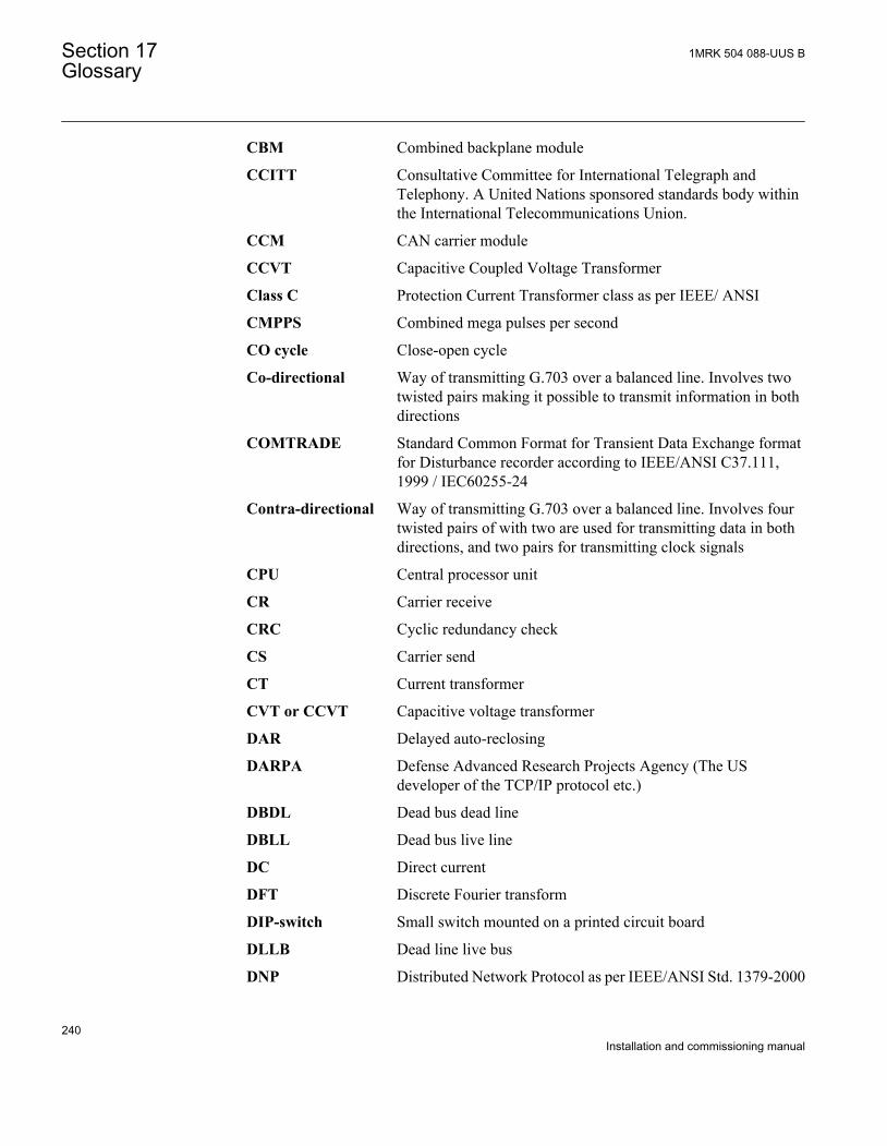
CBM Combined backplane module
CCITT Consultative Committee for International Telegraph andTelephony. A United Nations sponsored standards body withinthe International Telecommunications Union.
CCM CAN carrier module
CCVT Capacitive Coupled Voltage Transformer
Class C Protection Current Transformer class as per IEEE/ ANSI
CMPPS Combined mega pulses per second
CO cycle Close-open cycle
Co-directional Way of transmitting G.703 over a balanced line. Involves twotwisted pairs making it possible to transmit information in bothdirections
COMTRADE Standard Common Format for Transient Data Exchange formatfor Disturbance recorder according to IEEE/ANSI C37.111,1999 / IEC60255-24
Contra-directional Way of transmitting G.703 over a balanced line. Involves fourtwisted pairs of with two are used for transmitting data in bothdirections, and two pairs for transmitting clock signals
CPU Central processor unit
CR Carrier receive
CRC Cyclic redundancy check
CS Carrier send
CT Current transformer
CVT or CCVT Capacitive voltage transformer
DAR Delayed auto-reclosing
DARPA Defense Advanced Research Projects Agency (The USdeveloper of the TCP/IP protocol etc.)
DBDL Dead bus dead line
DBLL Dead bus live line
DC Direct current
DFT Discrete Fourier transform
DIP-switch Small switch mounted on a printed circuit board
DLLB Dead line live bus
DNP Distributed Network Protocol as per IEEE/ANSI Std. 1379-2000
Section 17 1MRK 504 088-UUS BGlossary
240Installation and commissioning manual
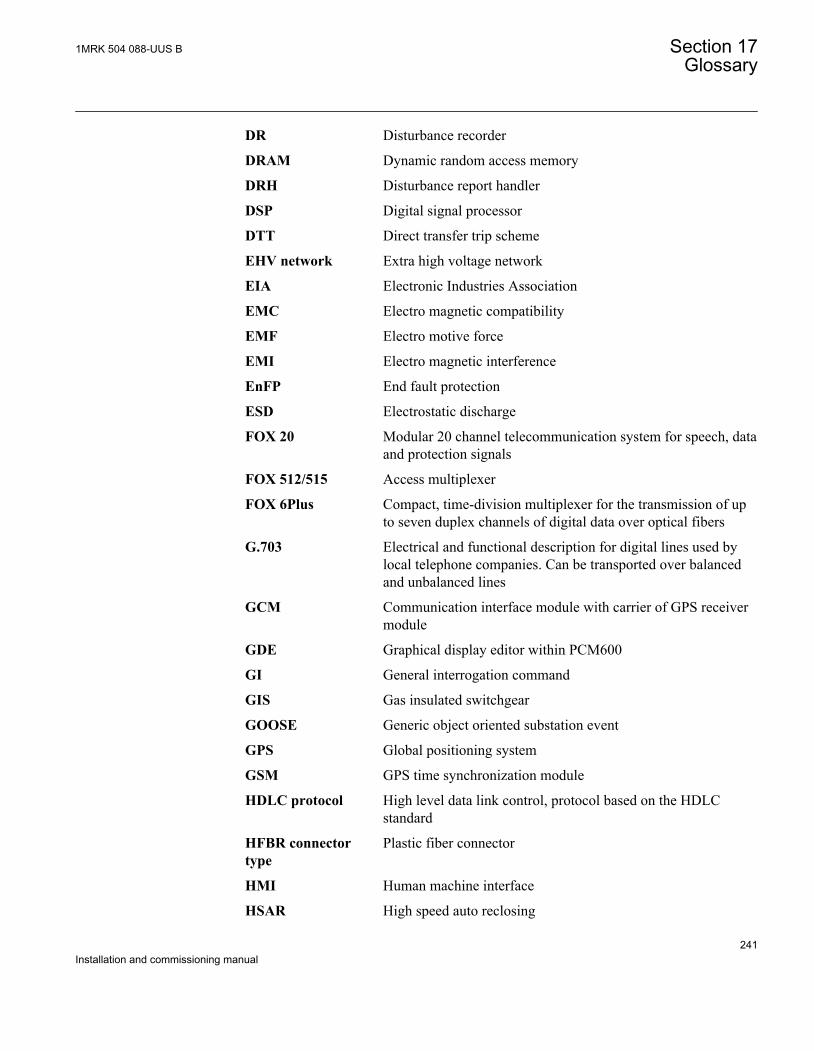
DR Disturbance recorder
DRAM Dynamic random access memory
DRH Disturbance report handler
DSP Digital signal processor
DTT Direct transfer trip scheme
EHV network Extra high voltage network
EIA Electronic Industries Association
EMC Electro magnetic compatibility
EMF Electro motive force
EMI Electro magnetic interference
EnFP End fault protection
ESD Electrostatic discharge
FOX 20 Modular 20 channel telecommunication system for speech, dataand protection signals
FOX 512/515 Access multiplexer
FOX 6Plus Compact, time-division multiplexer for the transmission of upto seven duplex channels of digital data over optical fibers
G.703 Electrical and functional description for digital lines used bylocal telephone companies. Can be transported over balancedand unbalanced lines
GCM Communication interface module with carrier of GPS receivermodule
GDE Graphical display editor within PCM600
GI General interrogation command
GIS Gas insulated switchgear
GOOSE Generic object oriented substation event
GPS Global positioning system
GSM GPS time synchronization module
HDLC protocol High level data link control, protocol based on the HDLCstandard
HFBR connectortype
Plastic fiber connector
HMI Human machine interface
HSAR High speed auto reclosing
1MRK 504 088-UUS B Section 17Glossary
241Installation and commissioning manual
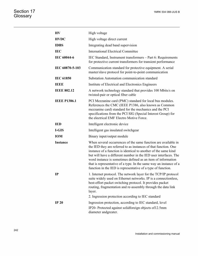
HV High voltage
HVDC High voltage direct current
IDBS Integrating dead band supervision
IEC International Electrical Committee
IEC 60044-6 IEC Standard, Instrument transformers – Part 6: Requirementsfor protective current transformers for transient performance
IEC 60870-5-103 Communication standard for protective equipment. A serialmaster/slave protocol for point-to-point communication
IEC 61850 Substation Automation communication standard
IEEE Institute of Electrical and Electronics Engineers
IEEE 802.12 A network technology standard that provides 100 Mbits/s ontwisted-pair or optical fiber cable
IEEE P1386.1 PCI Mezzanine card (PMC) standard for local bus modules.References the CMC (IEEE P1386, also known as Commonmezzanine card) standard for the mechanics and the PCIspecifications from the PCI SIG (Special Interest Group) forthe electrical EMF Electro Motive Force.
IED Intelligent electronic device
I-GIS Intelligent gas insulated switchgear
IOM Binary input/output module
Instance When several occurrences of the same function are available inthe IED they are referred to as instances of that function. Oneinstance of a function is identical to another of the same kindbut will have a different number in the IED user interfaces. Theword instance is sometimes defined as an item of informationthat is representative of a type. In the same way an instance of afunction in the IED is representative of a type of function.
IP 1. Internet protocol. The network layer for the TCP/IP protocolsuite widely used on Ethernet networks. IP is a connectionless,best-effort packet switching protocol. It provides packetrouting, fragmentation and re-assembly through the data linklayer.2. Ingression protection according to IEC standard
IP 20 Ingression protection, according to IEC standard, levelIP20- Protected against solidforeign objects of12.5mmdiameter andgreater.
Section 17 1MRK 504 088-UUS BGlossary
242Installation and commissioning manual
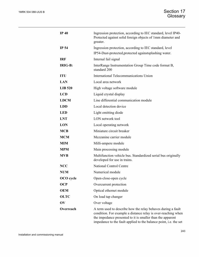
IP 40 Ingression protection, according to IEC standard, level IP40-Protected against solid foreign objects of 1mm diameter andgreater.
IP 54 Ingression protection, according to IEC standard, levelIP54-Dust-protected,protected againstsplashing water.
IRF Internal fail signal
IRIG-B: InterRange Instrumentation Group Time code format B,standard 200
ITU International Telecommunications Union
LAN Local area network
LIB 520 High voltage software module
LCD Liquid crystal display
LDCM Line differential communication module
LDD Local detection device
LED Light emitting diode
LNT LON network tool
LON Local operating network
MCB Miniature circuit breaker
MCM Mezzanine carrier module
MIM Milli-ampere module
MPM Main processing module
MVB Multifunction vehicle bus. Standardized serial bus originallydeveloped for use in trains.
NCC National Control Centre
NUM Numerical module
OCO cycle Open-close-open cycle
OCP Overcurrent protection
OEM Optical ethernet module
OLTC On load tap changer
OV Over voltage
Overreach A term used to describe how the relay behaves during a faultcondition. For example a distance relay is over-reaching whenthe impedance presented to it is smaller than the apparentimpedance to the fault applied to the balance point, i.e. the set
1MRK 504 088-UUS B Section 17Glossary
243Installation and commissioning manual
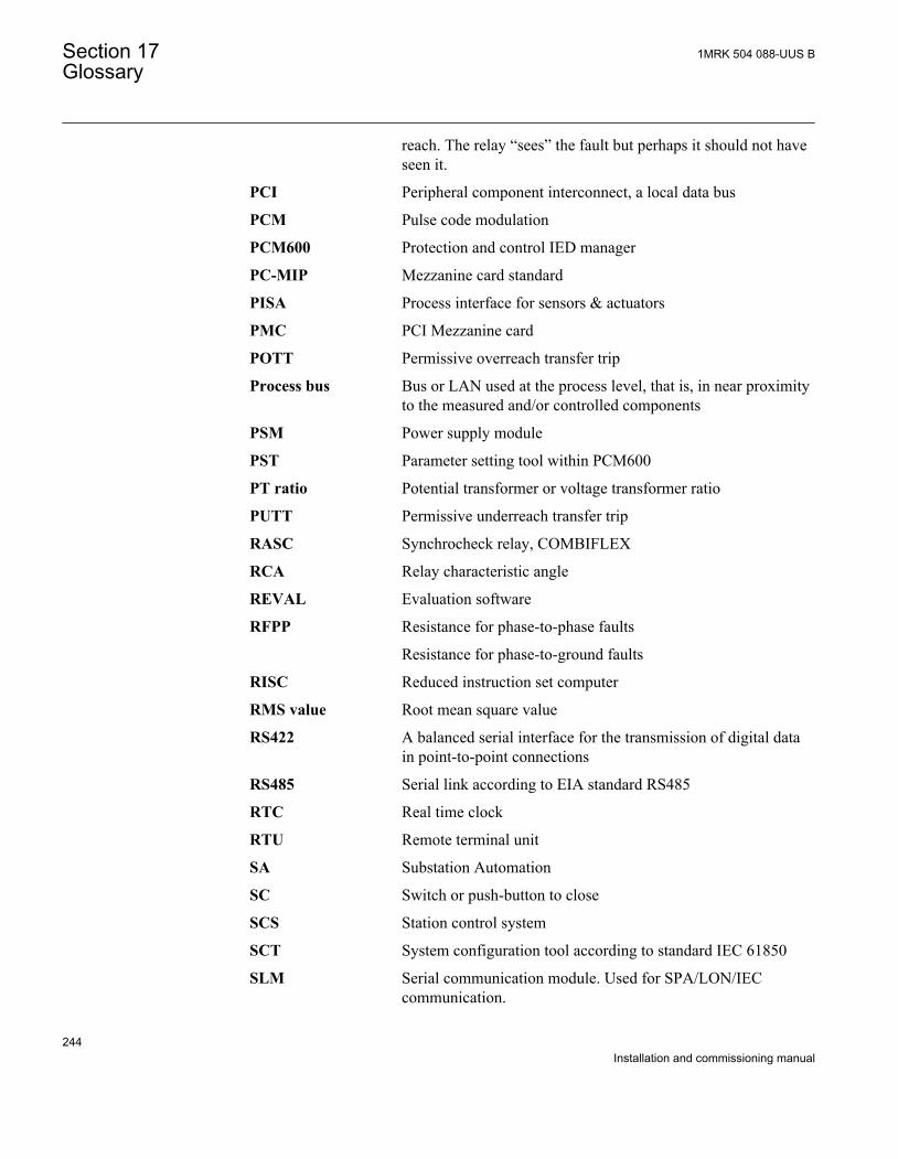
reach. The relay “sees” the fault but perhaps it should not haveseen it.
PCI Peripheral component interconnect, a local data bus
PCM Pulse code modulation
PCM600 Protection and control IED manager
PC-MIP Mezzanine card standard
PISA Process interface for sensors & actuators
PMC PCI Mezzanine card
POTT Permissive overreach transfer trip
Process bus Bus or LAN used at the process level, that is, in near proximityto the measured and/or controlled components
PSM Power supply module
PST Parameter setting tool within PCM600
PT ratio Potential transformer or voltage transformer ratio
PUTT Permissive underreach transfer trip
RASC Synchrocheck relay, COMBIFLEX
RCA Relay characteristic angle
REVAL Evaluation software
RFPP Resistance for phase-to-phase faults
Resistance for phase-to-ground faults
RISC Reduced instruction set computer
RMS value Root mean square value
RS422 A balanced serial interface for the transmission of digital datain point-to-point connections
RS485 Serial link according to EIA standard RS485
RTC Real time clock
RTU Remote terminal unit
SA Substation Automation
SC Switch or push-button to close
SCS Station control system
SCT System configuration tool according to standard IEC 61850
SLM Serial communication module. Used for SPA/LON/IECcommunication.
Section 17 1MRK 504 088-UUS BGlossary
244Installation and commissioning manual
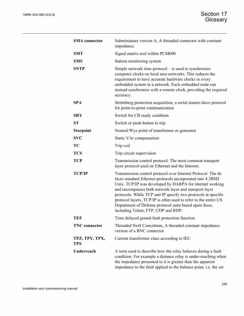
SMA connector Subminiature version A, A threaded connector with constantimpedance.
SMT Signal matrix tool within PCM600
SMS Station monitoring system
SNTP Simple network time protocol – is used to synchronizecomputer clocks on local area networks. This reduces therequirement to have accurate hardware clocks in everyembedded system in a network. Each embedded node caninstead synchronize with a remote clock, providing the requiredaccuracy.
SPA Strömberg protection acquisition, a serial master/slave protocolfor point-to-point communication
SRY Switch for CB ready condition
ST Switch or push-button to trip
Starpoint Neutral/Wye point of transformer or generator
SVC Static VAr compensation
TC Trip coil
TCS Trip circuit supervision
TCP Transmission control protocol. The most common transportlayer protocol used on Ethernet and the Internet.
TCP/IP Transmission control protocol over Internet Protocol. The defacto standard Ethernet protocols incorporated into 4.2BSDUnix. TCP/IP was developed by DARPA for internet workingand encompasses both network layer and transport layerprotocols. While TCP and IP specify two protocols at specificprotocol layers, TCP/IP is often used to refer to the entire USDepartment of Defense protocol suite based upon these,including Telnet, FTP, UDP and RDP.
TEF Time delayed gound-fault protection function
TNC connector Threaded Neill Concelman, A threaded constant impedanceversion of a BNC connector
TPZ, TPY, TPX,TPS
Current transformer class according to IEC
Underreach A term used to describe how the relay behaves during a faultcondition. For example a distance relay is under-reaching whenthe impedance presented to it is greater than the apparentimpedance to the fault applied to the balance point, i.e. the set
1MRK 504 088-UUS B Section 17Glossary
245Installation and commissioning manual
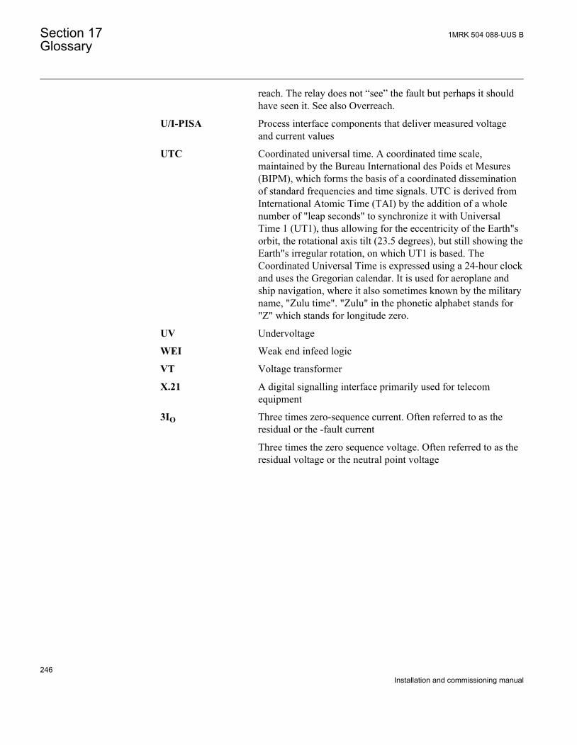
reach. The relay does not “see” the fault but perhaps it shouldhave seen it. See also Overreach.
U/I-PISA Process interface components that deliver measured voltageand current values
UTC Coordinated universal time. A coordinated time scale,maintained by the Bureau International des Poids et Mesures(BIPM), which forms the basis of a coordinated disseminationof standard frequencies and time signals. UTC is derived fromInternational Atomic Time (TAI) by the addition of a wholenumber of "leap seconds" to synchronize it with UniversalTime 1 (UT1), thus allowing for the eccentricity of the Earth"sorbit, the rotational axis tilt (23.5 degrees), but still showing theEarth"s irregular rotation, on which UT1 is based. TheCoordinated Universal Time is expressed using a 24-hour clockand uses the Gregorian calendar. It is used for aeroplane andship navigation, where it also sometimes known by the militaryname, "Zulu time". "Zulu" in the phonetic alphabet stands for"Z" which stands for longitude zero.
UV Undervoltage
WEI Weak end infeed logic
VT Voltage transformer
X.21 A digital signalling interface primarily used for telecomequipment
3IO Three times zero-sequence current. Often referred to as theresidual or the -fault current
Three times the zero sequence voltage. Often referred to as theresidual voltage or the neutral point voltage
Section 17 1MRK 504 088-UUS BGlossary
246Installation and commissioning manual

247

Contact us
ABB Inc.940 Main Campus DriveRaleigh, NC 27606, USAPhone Toll Free: 1-800-HELP-365,menu option #8
ABB Inc.3450 Harvester RoadBurlington, ON L7N 3W5, CanadaPhone Toll Free: 1-800-HELP-365,menu option #8
ABB Mexico S.A. de C.V.Paseo de las Americas No. 31 LomasVerdes 3a secc.53125, Naucalpan, Estado De Mexico,MEXICOPhone (+1) 440-585-7804, menuoption #8
1MR
K 5
04 0
88-U
US
B©
Cop
yrig
ht 2
010
AB
B. A
ll rig
hts
rese
rved
.


![[NN40040-600] CallPilot Contact Center Telephone Administration Guide€¦ · · 2014-08-19About Contact Center telephone administration . . . . . . . . . . . . . . . . . . .](https://img.pdfslide.us/doc/110x75/5af5ac817f8b9a4d4d8f631c/nn40040-600-callpilot-contact-center-telephone-administration-2014-08-19about.jpg)