Embed Size (px)
Citation preview

eSPINNER® indoor cycling bike.
I N S TA L L AT I O N A N D
O P E R AT I O N M A N U A L

2

3
CORPORATE HEADQUARTERS 14410 Myford Road
Irvine, CA 92606 USA Phone +1 714 669 1660
Fax +1 714 669 0287 800 228 6635 (toll-free within the U.S.A., Canada)
Star Trac Europe
Unit 4, The Gateway Centre, Coronation Road Cressex Business Park, High Wycombe,
Bucks HP12 3SU United Kingdom Phone +44 (0) 1494 688260
Fax +44 (0) 1494 688269
Star Trac Asia No. 39A Jalan Pemimpin, Halcyon Building #01-02
Singapore 577183 Phone +65 6255 6252
Fax +65 6255 1501
Copyright 2008. Star Trac by Unisen, Inc. Star Trac Fitness, Star Trac®, and the Star Trac Logo are registered trademarks of Unisen Inc. All rights reserved, including those to reproduce this book or parts thereof in any form without first obtaining written permission from Star Trac. Spin®, Spinner®, Spinning® and the Spinning logo are registered trademarks of Mad Dogg Athletics, Inc. Apple, iPod, iTunes, iPhone, iTouch, and the Apple logo are a register trademarks of Apple, Inc. Smart Release™ is a registered trademark of Nautilus, Inc. SPD is a registered trademark of Shimano American Corporation. Every effort has been made to keep this information current; however, periodically, changes are made to the information herein, and these changes will be incorporated into new editions of this publication. All product names and logos are trademarks of their respective owners. Printed in the USA.

4
Before using this product, it is essential to read this ENTIRE operations manual and ALL instal-lation Instructions. It describes equipment setup and instructs users and members on how to use it correctly and safely.
Health related injuries may result from incorrect or excessive use of exercise equipment. Star Trac strongly recommends you and your members to discuss their health program or fitness regimen with a health care professional, especially if they have not exercised for several years, are over 35, or have known health conditions.
5
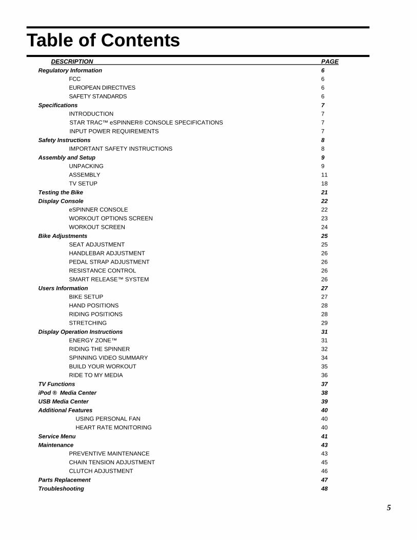
Table of Contents DESCRIPTION PAGE Regulatory Information 6
FCC 6 EUROPEAN DIRECTIVES 6 SAFETY STANDARDS 6
Specifications 7 INTRODUCTION 7 STAR TRAC™ eSPINNER® CONSOLE SPECIFICATIONS 7 INPUT POWER REQUIREMENTS 7
Safety Instructions 8 IMPORTANT SAFETY INSTRUCTIONS 8
Assembly and Setup 9 UNPACKING 9 ASSEMBLY 11 TV SETUP 18
Testing the Bike 21 Display Console 22
eSPINNER CONSOLE 22 WORKOUT OPTIONS SCREEN 23 WORKOUT SCREEN 24
Bike Adjustments 25 SEAT ADJUSTMENT 25 HANDLEBAR ADJUSTMENT 26 PEDAL STRAP ADJUSTMENT 26 RESISTANCE CONTROL 26 SMART RELEASE™ SYSTEM 26
Users Information 27 BIKE SETUP 27 HAND POSITIONS 28 RIDING POSITIONS 28 STRETCHING 29
Display Operation Instructions 31 ENERGY ZONE™ 31 RIDING THE SPINNER 32 SPINNING VIDEO SUMMARY 34 BUILD YOUR WORKOUT 35 RIDE TO MY MEDIA 36
TV Functions 37 iPod ® Media Center 38 USB Media Center 39 Additional Features 40
USING PERSONAL FAN 40 HEART RATE MONITORING 40 Service Menu 41 Maintenance 43
PREVENTIVE MAINTENANCE 43 CHAIN TENSION ADJUSTMENT 45 CLUTCH ADJUSTMENT 46
Parts Replacement 47 Troubleshooting 48

6
Regulatory Information FCC The eSpinner® has been tested and found to comply with the limits for a Class A digital device pursuant to Part 15 of FCC rules. Under the FCC guidelines, operation is subject to the following two guidelines: (1) this device may not cause harmful interference, and (2) this device must accept any interference received, including interference that may cause undesired operation.
The STAR TRAC eSpinner generates and uses radio frequency energy. If the products are not installed and used in ac-cordance with the instructions provided in the manual, interference with radio communications may occur. Likewise, if unapproved accessories are installed, interference with radio communications may occur. The intent of the FCC Class A limit is to provide reasonable protection against harmful interference in a COMMERCIAL environment. However, there is no guarantee that interference may not occur in a specific installation. In the event that interference is experienced, turn off the unit to verify that it is in fact the source. If the interference clears with the unit off, then try each of the following measures and combinations thereof:
• Reorient or relocate the product. • Reorient or relocate the receiving antenna of your television, radio, and / or VCR recorder. • Connect the unit to a different power outlet. • Consult Star Trac Product Support, your authorized dealer, or a qualified radio / television technician for as-
sistance. EUROPEAN DIRECTIVES This product, when used in conjunction with the approved cardio equipment, conforms to the requirements of the Euro-pean Council directives:
• 89/336/ECC, Electromagnetic Compatibility • 92/590/EEC, General Product Safety Directives • 73/23/EEC, Electrical equipment Low Voltage Safety Directive
SAFETY STANDARDS This product has been tested and/or verified, in conjunction with the approved cardio equipment, to meet the following standards:
• UL 1647 Safety for Motor operated Massage and Exercise Machines • CAN/CSA E335-1/3E-94 Safety of Motor Operated Appliances (Household and Commercial) • EN 60355-1 Safety of the household and Similar Electrical appliance • EN957-1 General safety requirements and test methods • EN 957-5 Pedal Crank Training Equipment, additional safety requirements • EN 957-10 Exercise bicycles with a fixed or without flywheel, additional safety requirements & test methods
7
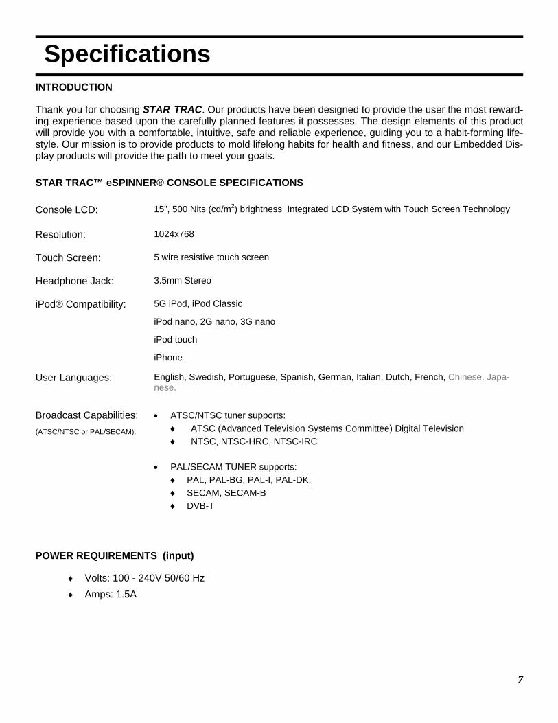
Specifications INTRODUCTION
Thank you for choosing STAR TRAC. Our products have been designed to provide the user the most reward-ing experience based upon the carefully planned features it possesses. The design elements of this product will provide you with a comfortable, intuitive, safe and reliable experience, guiding you to a habit-forming life-style. Our mission is to provide products to mold lifelong habits for health and fitness, and our Embedded Dis-play products will provide the path to meet your goals.
STAR TRAC™ eSPINNER® CONSOLE SPECIFICATIONS
Console LCD: 15”, 500 Nits (cd/m2) brightness Integrated LCD System with Touch Screen Technology
Resolution: 1024x768
Touch Screen: 5 wire resistive touch screen
Headphone Jack: 3.5mm Stereo
iPod® Compatibility:
5G iPod, iPod Classic
iPod nano, 2G nano, 3G nano
iPod touch
iPhone
User Languages: English, Swedish, Portuguese, Spanish, German, Italian, Dutch, French, Chinese, Japa-nese.
Broadcast Capabilities: (ATSC/NTSC or PAL/SECAM).
• ATSC/NTSC tuner supports: ♦ ATSC (Advanced Television Systems Committee) Digital Television ♦ NTSC, NTSC-HRC, NTSC-IRC
• PAL/SECAM TUNER supports: ♦ PAL, PAL-BG, PAL-I, PAL-DK, ♦ SECAM, SECAM-B ♦ DVB-T
POWER REQUIREMENTS (input)
♦ Volts: 100 - 240V 50/60 Hz ♦ Amps: 1.5A
8
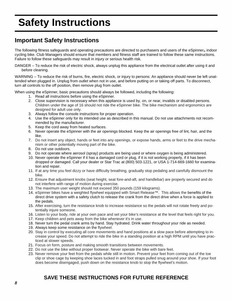
Safety Instructions Important Safety Instructions The following fitness safeguards and operating precautions are directed to purchasers and users of the eSpinner® indoor cycling bike. Club Managers should ensure that members and fitness staff are trained to follow these same instructions. Failure to follow these safeguards may result in injury or serious health risk.
DANGER – To reduce the risk of electric shock, always unplug this appliance from the electrical outlet after using it and before cleaning.
WARNING – To reduce the risk of burns, fire, electric shock, or injury to persons: An appliance should never be left unat-tended when plugged in. Unplug from outlet when not in use, and before putting on or taking off parts. To disconnect, turn all controls to the off position, then remove plug from outlet.
When using the eSpinner, basic precautions should always be followed, including the following: 1. Read all instructions before using the eSpinner. 2. Close supervision is necessary when this appliance is used by, on, or near, invalids or disabled persons.
Children under the age of 16 should not ride the eSpinner bike. The bike mechanism and ergonomics are designed for adult use only.
3. Always follow the console instructions for proper operation. 4. Use the eSpinner only for its intended use as described in this manual. Do not use attachments not recom-
mended by the manufacturer. 5. Keep the cord away from heated surfaces. 6. Never operate the eSpinner with the air openings blocked. Keep the air openings free of lint, hair, and the
like. 7. Do not insert any object, hands or feet into any openings, or expose hands, arms or feet to the drive mecha-
nism or other potentially moving part of the bike. 8. Do not use outdoors. 9. Do not operate where aerosol (spray) products are being used or where oxygen is being administered. 10. Never operate the eSpinner if it has a damaged cord or plug, if it is not working properly, if it has been
dropped or damaged. Call your dealer or Star Trac at (800) 503-1221, or USA 1-714-669-1660 for examina-tion and repair.
11. If at any time you feel dizzy or have difficulty breathing, gradually stop pedaling and carefully dismount the bike.
12. Ensure that adjustment knobs (seat height, seat fore-and-aft, and handlebar) are properly secured and do not interfere with range of motion during exercise.
13. The maximum user weight should not exceed 350 pounds (159 kilograms). 14. eSpinner bikes have a weighted flywheel equipped with Smart Release™. This allows the benefits of the
direct drive system with a safety clutch to release the crank from the direct drive when a force is applied to the pedals.
15. After exercising, turn the resistance knob to increase resistance so the pedals will not rotate freely and po-tentially injure someone.
16. Listen to your body, ride at your own pace and set your bike’s resistance at the level that feels right for you. 17. Keep children and pets away from the bike whenever it's in use. 18. Never turn the pedal crank arms by hand. Stay hydrated. Drink water throughout your ride as needed. 19. Always keep some resistance on the flywheel. 20. Stay in control by executing all core movements and hand positions at a slow pace before attempting to in-
crease your speed. Do not attempt to ride the bike in a standing position at a high RPM until you have prac-ticed at slower speeds.
21. Focus on form, posture and making smooth transitions between movements. 22. Do not use the bike without proper footwear. Never operate the bike with bare feet. 23. Never remove your feet from the pedals while still in motion. Prevent your feet from coming out of the toe
clip or shoe cage by keeping shoe laces tucked in and foot straps pulled snug around your shoe. If your foot does become disengaged, push down on the resistance knob to stop the flywheel’s motion.
SAVE THESE INSTRUCTIONS FOR FUTURE REFERENCE
9
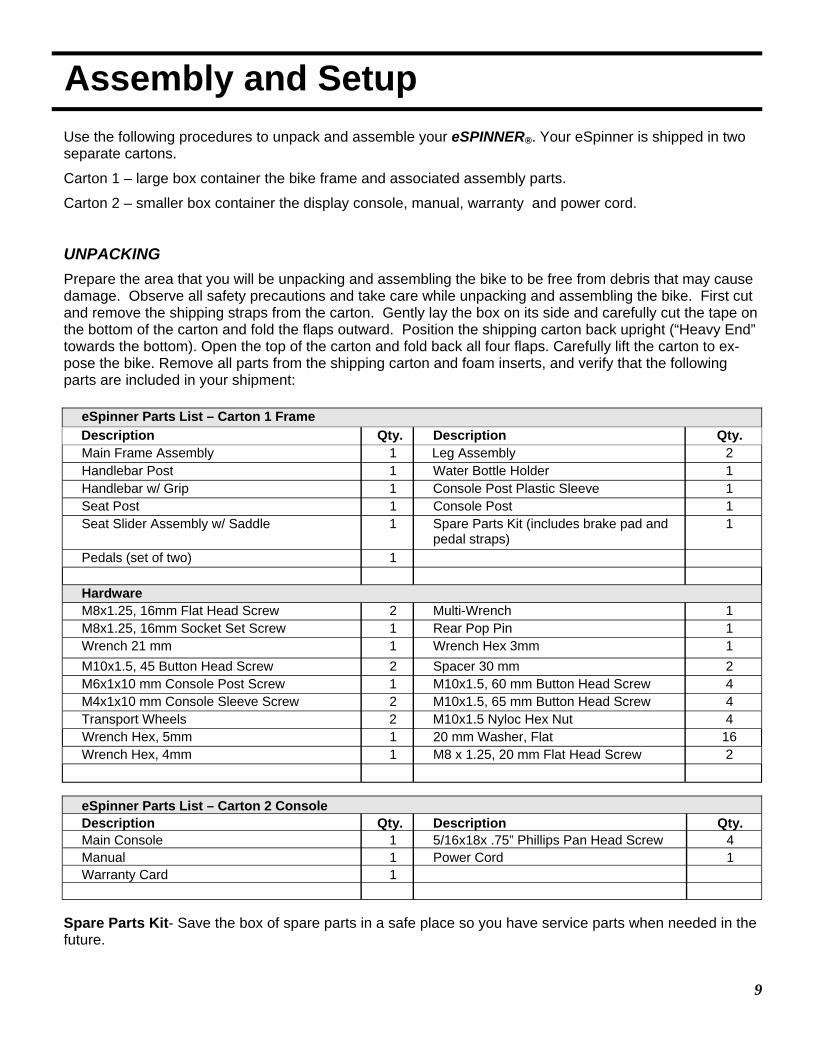
Assembly and Setup
Use the following procedures to unpack and assemble your eSPINNER®. Your eSpinner is shipped in two separate cartons.
Carton 1 – large box container the bike frame and associated assembly parts.
Carton 2 – smaller box container the display console, manual, warranty and power cord.
UNPACKING Prepare the area that you will be unpacking and assembling the bike to be free from debris that may cause damage. Observe all safety precautions and take care while unpacking and assembling the bike. First cut and remove the shipping straps from the carton. Gently lay the box on its side and carefully cut the tape on the bottom of the carton and fold the flaps outward. Position the shipping carton back upright (“Heavy End” towards the bottom). Open the top of the carton and fold back all four flaps. Carefully lift the carton to ex-pose the bike. Remove all parts from the shipping carton and foam inserts, and verify that the following parts are included in your shipment:
eSpinner Parts List – Carton 1 Frame Description Qty. Description Qty. Main Frame Assembly 1 Leg Assembly 2 Handlebar Post 1 Water Bottle Holder 1 Handlebar w/ Grip 1 Console Post Plastic Sleeve 1 Seat Post 1 Console Post 1 Seat Slider Assembly w/ Saddle 1 Spare Parts Kit (includes brake pad and
pedal straps) 1
Pedals (set of two) 1 Hardware M8x1.25, 16mm Flat Head Screw 2 Multi-Wrench 1 M8x1.25, 16mm Socket Set Screw 1 Rear Pop Pin 1 Wrench 21 mm 1 Wrench Hex 3mm 1 M10x1.5, 45 Button Head Screw 2 Spacer 30 mm 2 M6x1x10 mm Console Post Screw 1 M10x1.5, 60 mm Button Head Screw 4 M4x1x10 mm Console Sleeve Screw 2 M10x1.5, 65 mm Button Head Screw 4 Transport Wheels 2 M10x1.5 Nyloc Hex Nut 4 Wrench Hex, 5mm 1 20 mm Washer, Flat 16 Wrench Hex, 4mm 1 M8 x 1.25, 20 mm Flat Head Screw 2
eSpinner Parts List – Carton 2 Console Description Qty. Description Qty. Main Console 1 5/16x18x .75” Phillips Pan Head Screw 4 Manual 1 Power Cord 1 Warranty Card 1
Spare Parts Kit- Save the box of spare parts in a safe place so you have service parts when needed in the future.
10
Assembly and Setup
Take time now to enter your eSpinner® serial number in the space below (serial number is located between the forks on the main frame ). If parts are missing, or if you have any operational questions, please call Star Trac’s Service department at (800) 503-1221; have your serial number ready.
Serial No._____________________________________________
NOTE: If you are missing any of the parts listed above, inspect the packing material and the box for items that may have been overlooked. If parts are missing, or if you have any product questions, please call Star Trac’s Service Department at (800) 503-1221, please have your eSpinner’s serial number ready.
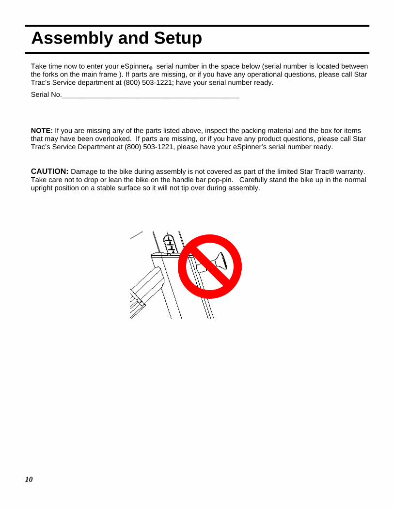
CAUTION: Damage to the bike during assembly is not covered as part of the limited Star Trac® warranty. Take care not to drop or lean the bike on the handle bar pop-pin. Carefully stand the bike up in the normal upright position on a stable surface so it will not tip over during assembly.
11
Assembly and Setup
ASSEMBLY WARNING – DO NOT USE POWER TOOLS or POWER DRIVE ASSEMBLY TOOLS DURING THE AS-SEMBLY OF THE eSPINNER. FAILURE TO FOLLOW THESE INSTRUCTIONS MAY DAMAGE THE PRODUCT DURING ASSEMBLY WHICH IS NOT COVERED UNDER THE STAR TRAC WARRANTY.
Following these steps in order will minimize the build time and ensure proper assembly.
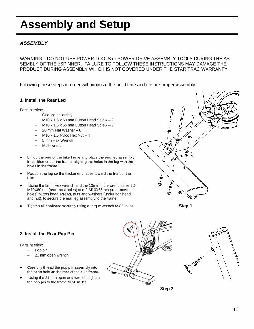
1. Install the Rear Leg Parts needed:
− One leg assembly − M10 x 1.5 x 60 mm Button Head Screw – 2 − M10 x 1.5 x 65 mm Button Head Screw – 2 − 20 mm Flat Washer – 8 − M10 x 1.5 Nyloc Hex Nut – 4 − 5 mm Hex Wrench − Multi-wrench
♦ Lift up the rear of the bike frame and place the rear leg assembly in position under the frame, aligning the holes in the leg with the holes in the frame.
♦ Position the leg so the thicker end faces toward the front of the bike
♦ Using the 5mm Hex wrench and the 13mm multi-wrench insert 2- M10X60mm (rear-most holes) and 2-M10X65mm (front-most holes) button head screws, nuts and washers (under bolt head and nut), to secure the rear leg assembly to the frame.
♦ Tighten all hardware securely using a torque wrench to 85 in-lbs.
2. Install the Rear Pop Pin Parts needed:
− Pop pin − 21 mm open wrench
♦ Carefully thread the pop pin assembly into the open hole on the rear of the bike frame.
♦ Using the 21 mm open end wrench, tighten the pop pin to the frame to 50 in-lbs.
Step 1
Step 2
12
Assembly and Setup
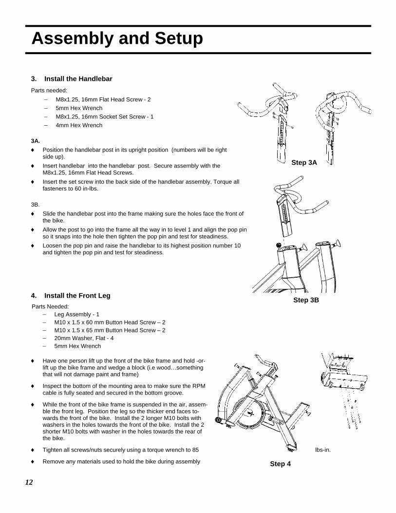
3. Install the Handlebar Parts needed:
− M8x1.25, 16mm Flat Head Screw - 2 − 5mm Hex Wrench − M8x1.25, 16mm Socket Set Screw - 1 − 4mm Hex Wrench
3A. ♦ Position the handlebar post in its upright position (numbers will be right
side up). ♦ Insert handlebar into the handlebar post. Secure assembly with the
M8x1.25, 16mm Flat Head Screws. ♦ Insert the set screw into the back side of the handlebar assembly. Torque all
fasteners to 60 in-lbs. 3B. ♦ Slide the handlebar post into the frame making sure the holes face the front of
the bike. ♦ Allow the post to go into the frame all the way in to level 1 and align the pop pin
so it snaps into the hole then tighten the pop pin and test for steadiness. ♦ Loosen the pop pin and raise the handlebar to its highest position number 10
and tighten the pop pin and test for steadiness. 4. Install the Front Leg
Parts Needed: − Leg Assembly - 1 − M10 x 1.5 x 60 mm Button Head Screw – 2 − M10 x 1.5 x 65 mm Button Head Screw – 2 − 20mm Washer, Flat - 4 − 5mm Hex Wrench
♦ Have one person lift up the front of the bike frame and hold -or-
lift up the bike frame and wedge a block (i.e wood…something that will not damage paint and frame)
♦ Inspect the bottom of the mounting area to make sure the RPM cable is fully seated and secured in the bottom groove.
♦ While the front of the bike frame is suspended in the air, assem-ble the front leg. Position the leg so the thicker end faces to-wards the front of the bike. Install the 2 longer M10 bolts with washers in the holes towards the front of the bike. Install the 2 shorter M10 bolts with washer in the holes towards the rear of the bike.
♦ Tighten all screws/nuts securely using a torque wrench to 85 lbs-in.
♦ Remove any materials used to hold the bike during assembly
Step 3A
Step 3B
Step 4
13
Assembly and Setup
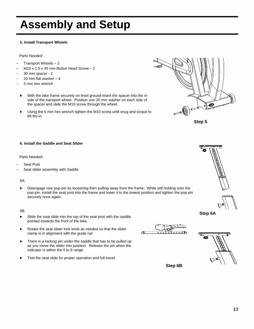
5. Install Transport Wheels
Parts Needed:
− Transport Wheels – 2 − M10 x 1.5 x 45 mm Button Head Screw – 2 − 30 mm spacer - 2 − 20 mm flat washer – 4 − 5 mm hex wrench
♦ With the bike frame securely on level ground insert the spacer into the in-side of the transport wheel. Position one 20 mm washer on each side of the spacer and slide the M10 screw through the wheel.
♦ Using the 5 mm hex wrench tighten the M10 screw until snug and torque to 85 lbs-in.
6. Install the Saddle and Seat Slider
Parts Needed:
− Seat Post − Seat slider assembly with Saddle
6A.
♦ Disengage rear pop-pin by loosening then pulling away from the frame. While still holding onto the pop-pin, install the seat post into the frame and lower it to the lowest position and tighten the pop pin securely once again.
6B. ♦ Slide the seat slide into the top of the seat post with the saddle
pointed towards the front of the bike.
♦ Rotate the seat slider lock knob as needed so that the slider clamp is in alignment with the guide rail
♦ There is a locking pin under the saddle that has to be pulled up as you move the slider into position. Release the pin when the indicator is within the 0 to 9 range.
♦ Test the seat slide for proper operation and full travel.
Step 5
Step 6A
Step 6B
14
Assembly and Setup
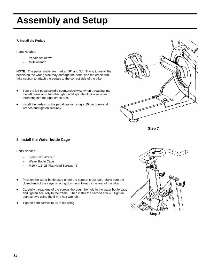
7. Install the Pedals
Parts Needed:
− Pedals set of two − Mutli wrench
NOTE: The pedal shafts are marked “R” and “L”. Trying to install the pedals on the wrong side may damage the pedal and the crank arm take caution to attach the pedals to the correct side of the bike.
♦ Turn the left pedal spindle counterclockwise when threading into the left crank arm; turn the right pedal spindle clockwise when threading into the right crank arm.
♦ Install the pedals on the pedal cranks using a 15mm open-end wrench and tighten securely.
8. Install the Water bottle Cage
Parts Needed:
− 5 mm Hex Wrench − Water Bottle Cage − M10 x 1.5, 25 Flat Head Screws - 2
♦ Position the water bottle cage under the support cross bar. Make sure the
closed end of the cage is facing down and towards the rear of the bike.
♦ Carefully thread one of the screws thorough the hole in the water bottle cage and tighten securely to the frame. Then install the second screw. Tighten both screws using the 5 mm hex wrench.
♦ Tighten both screws to 85 in lbs using.
Step 7
Step 8
15
Assembly and Setup
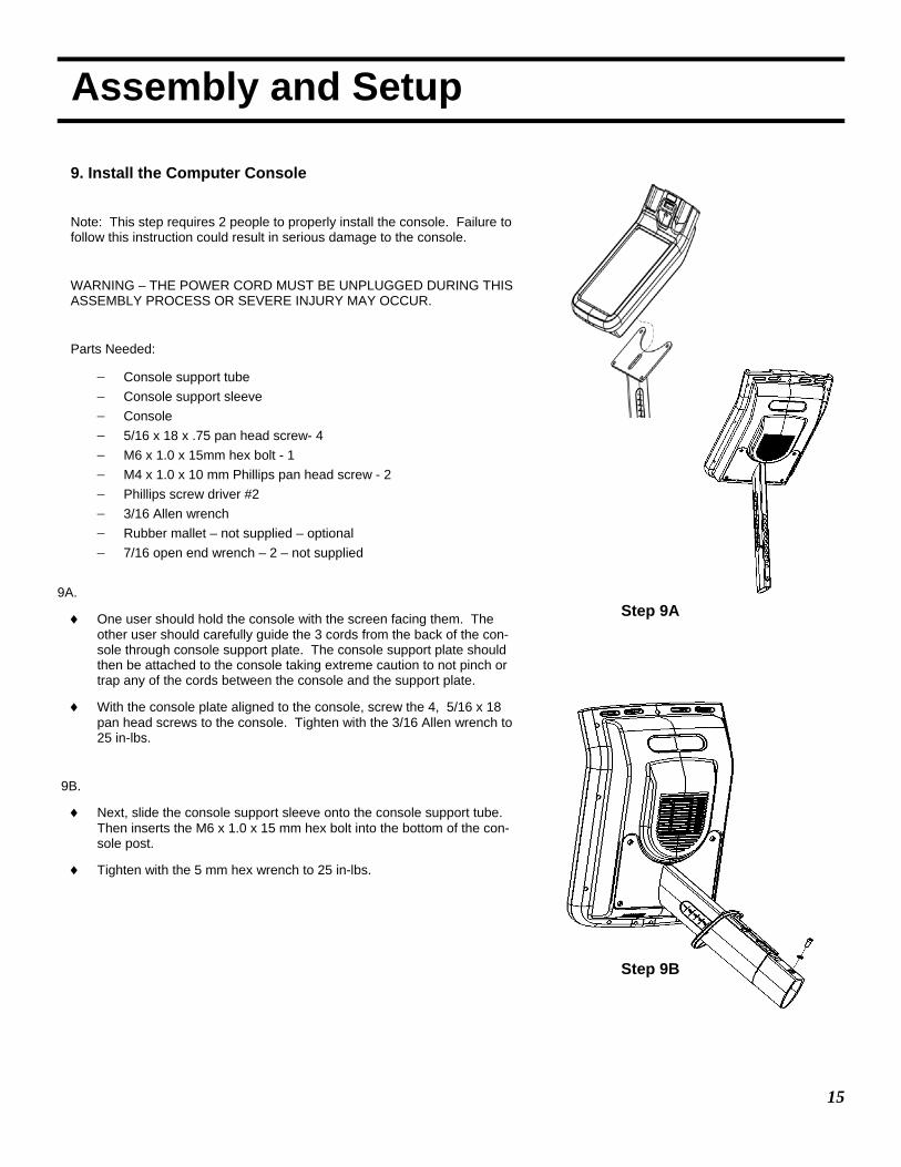
9. Install the Computer Console
Note: This step requires 2 people to properly install the console. Failure to follow this instruction could result in serious damage to the console.
WARNING – THE POWER CORD MUST BE UNPLUGGED DURING THIS ASSEMBLY PROCESS OR SEVERE INJURY MAY OCCUR.
Parts Needed:
− Console support tube − Console support sleeve − Console − 5/16 x 18 x .75 pan head screw- 4 − M6 x 1.0 x 15mm hex bolt - 1 − M4 x 1.0 x 10 mm Phillips pan head screw - 2 − Phillips screw driver #2 − 3/16 Allen wrench − Rubber mallet – not supplied – optional − 7/16 open end wrench – 2 – not supplied
9A.
♦ One user should hold the console with the screen facing them. The other user should carefully guide the 3 cords from the back of the con-sole through console support plate. The console support plate should then be attached to the console taking extreme caution to not pinch or trap any of the cords between the console and the support plate.
♦ With the console plate aligned to the console, screw the 4, 5/16 x 18 pan head screws to the console. Tighten with the 3/16 Allen wrench to 25 in-lbs.
9B.
♦ Next, slide the console support sleeve onto the console support tube. Then inserts the M6 x 1.0 x 15 mm hex bolt into the bottom of the con-sole post.
♦ Tighten with the 5 mm hex wrench to 25 in-lbs.
Step 9A
Step 9B
16
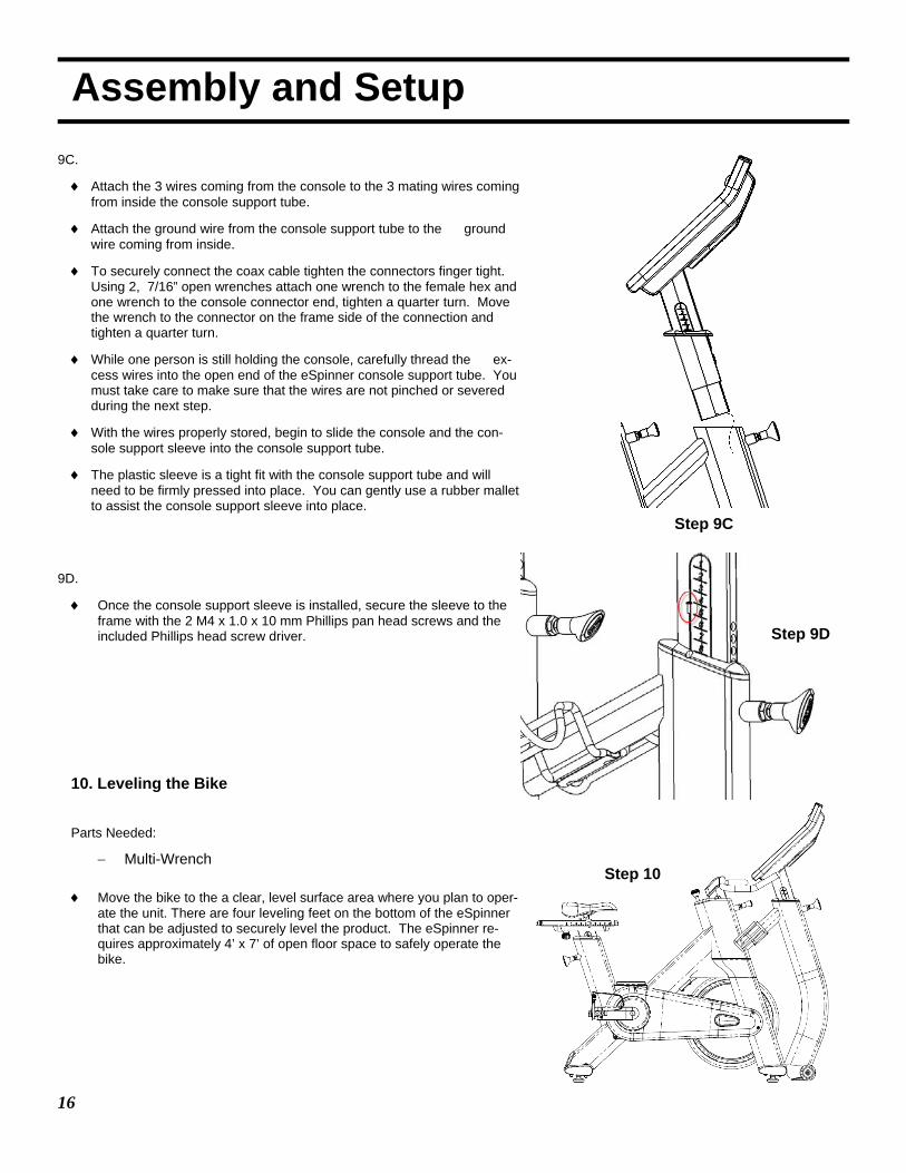
Assembly and Setup 9C.
♦ Attach the 3 wires coming from the console to the 3 mating wires coming from inside the console support tube.
♦ Attach the ground wire from the console support tube to the ground wire coming from inside.
♦ To securely connect the coax cable tighten the connectors finger tight. Using 2, 7/16” open wrenches attach one wrench to the female hex and one wrench to the console connector end, tighten a quarter turn. Move the wrench to the connector on the frame side of the connection and tighten a quarter turn.
♦ While one person is still holding the console, carefully thread the ex-cess wires into the open end of the eSpinner console support tube. You must take care to make sure that the wires are not pinched or severed during the next step.
♦ With the wires properly stored, begin to slide the console and the con-sole support sleeve into the console support tube.
♦ The plastic sleeve is a tight fit with the console support tube and will need to be firmly pressed into place. You can gently use a rubber mallet to assist the console support sleeve into place.
9D.
♦ Once the console support sleeve is installed, secure the sleeve to the frame with the 2 M4 x 1.0 x 10 mm Phillips pan head screws and the included Phillips head screw driver.
10. Leveling the Bike
Parts Needed:
− Multi-Wrench ♦ Move the bike to the a clear, level surface area where you plan to oper-
ate the unit. There are four leveling feet on the bottom of the eSpinner that can be adjusted to securely level the product. The eSpinner re-quires approximately 4’ x 7’ of open floor space to safely operate the bike.
Step 9C
Step 9D
Step 10
17
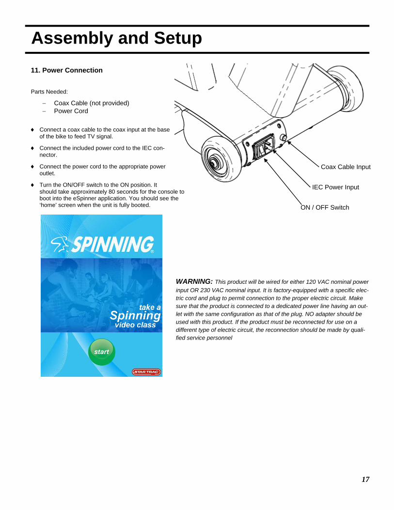
Assembly and Setup 11. Power Connection
Parts Needed:
− Coax Cable (not provided) − Power Cord
♦ Connect a coax cable to the coax input at the base of the bike to feed TV signal.
♦ Connect the included power cord to the IEC con-nector.
♦ Connect the power cord to the appropriate power outlet.
♦ Turn the ON/OFF switch to the ON position. It should take approximately 80 seconds for the console to boot into the eSpinner application. You should see the ‘home’ screen when the unit is fully booted.
Coax Cable Input
IEC Power Input
ON / OFF Switch
WARNING: This product will be wired for either 120 VAC nominal power input OR 230 VAC nominal input. It is factory-equipped with a specific elec-tric cord and plug to permit connection to the proper electric circuit. Make sure that the product is connected to a dedicated power line having an out-let with the same configuration as that of the plug. NO adapter should be used with this product. If the product must be reconnected for use on a different type of electric circuit, the reconnection should be made by quali-fied service personnel
18
Assembly and Setup
3
1 2
TV SETUP
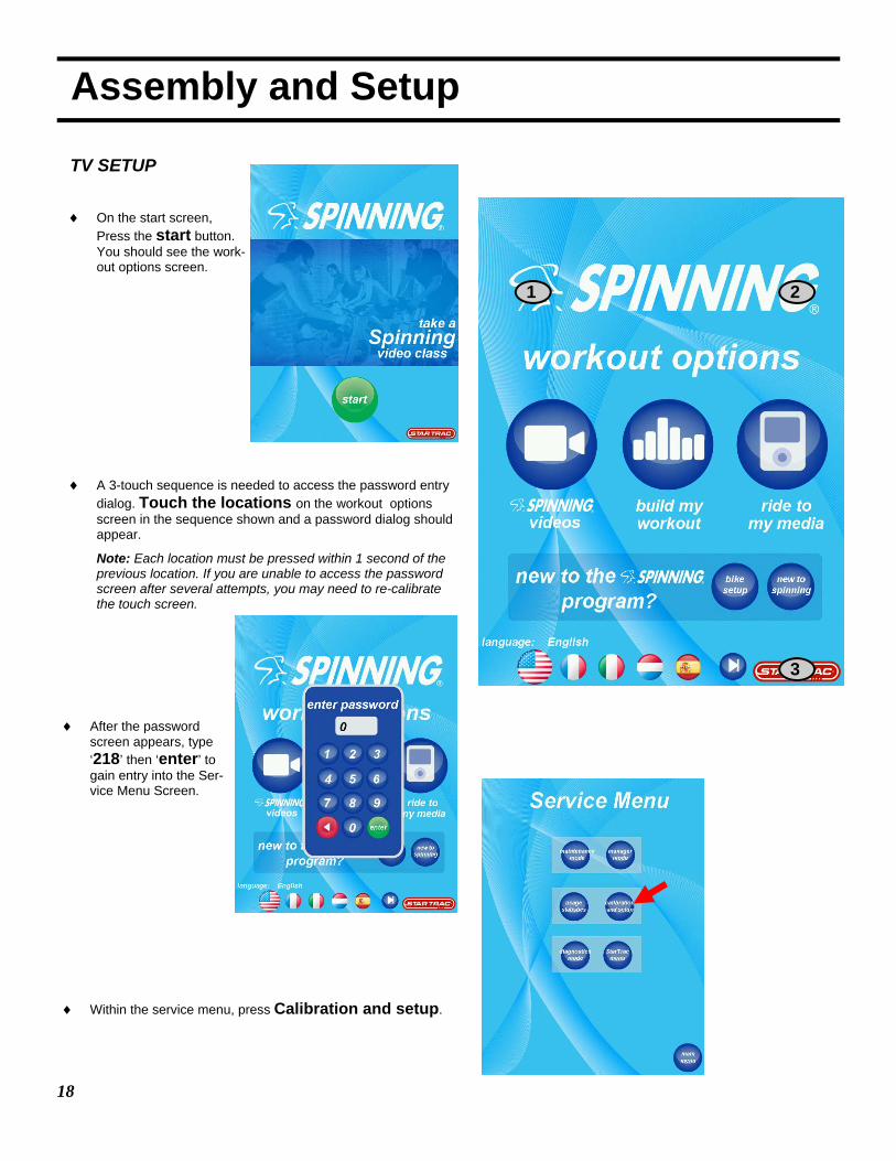
♦ On the start screen, Press the start button. You should see the work-out options screen.
♦ A 3-touch sequence is needed to access the password entry dialog. Touch the locations on the workout options screen in the sequence shown and a password dialog should appear.
Note: Each location must be pressed within 1 second of the previous location. If you are unable to access the password screen after several attempts, you may need to re-calibrate the touch screen.
♦ After the password screen appears, type ‘218’ then ‘enter’ to gain entry into the Ser-vice Menu Screen.
♦ Within the service menu, press Calibration and setup.

19
Assembly and Setup ♦ Once in the Calibration and Setup screen, press the tv setup button. The TV Setup screen will appear.
♦ Once in the TV Setup Screen, press the scan menu button to access the TV scan screen.
♦ Within the TV scan screen:
− press the change mode button repeatedly until the appropriate TV mode appears.
− Press the change type button to select the correct signal type appears.
Note: The following table outlines the options:
♦ Once the correct TV mode and type had been selected, press the start scan to perform the channel scan.
PAL / SECAM / DVB NTSC/ATSC TV mode Signal type TV mode Signal type
ATV Air
PAL_B_G ATV Air NTSC PAL_B_G
ATV Cable ATV STD
PAL_D_K ATV HRC PAL_I ATV IRC
ATV Cable
PAL_B_G DTV Air ATSC PAL_D_K
DTV Cable QAM STD
PAL_I QAM HRC SECAM_L QAM IRC
DTV Air DVB-T

20
Assembly and Setup
♦ A progress bar will indicate the scanning progress.
NOTE: you may stop the scan process at any time by press-ing the stop scan button. If you do so, only the channels scanned up to that point will be displayed.
♦ You may press the tv menu button to return to the TV scan screen.
♦ Once in the channel scan is completed, press the debug menu button twice to exit TV Setup mode into the workout options screen.
Congratulations, you have now completed the assembly and setup of your eSPINNER® . Enjoy the ride.
!Attention! Crank bolt must be re-torqued after the first 10 hours of use. Refer to Preventive Maintenance section.
21
Testing the Bike
Use this checklist to perform the bike test procedure.
Recheck all the bolts and make sure they are all tightened to the proper torque specification and no parts are missing.
Test the handlebar and seat post to make sure they move freely and you are able to lock in at different positions.
Check the seat to make sure it is level and tight and does not rotate around or tilt. Tighten and adjust as needed.
Test the seat slide for movement front to rear and check it by setting it at different settings.
CAUTION: The flywheel will continue to spin after you pedal and the crank arms and pedals will rotate with the flywheel.
Brake tension is adjustable using the red resistance knob in the front of the bike. Pressing down on the knob will apply the brake if you need to stop quickly.
Adjust seat post and handlebar post to your needs. Ride / test the bike for proper operation according to the owner's man-ual.
Pedal the bike at a moderate pace and test for proper and smooth resistance changes while varying the amount of turns on the resistance knob.
When the testing is complete tip the bike forward using the handlebars and roll it on a smooth surface to the final location and adjust the leveling feet so the bike is stable.
22
Display Console
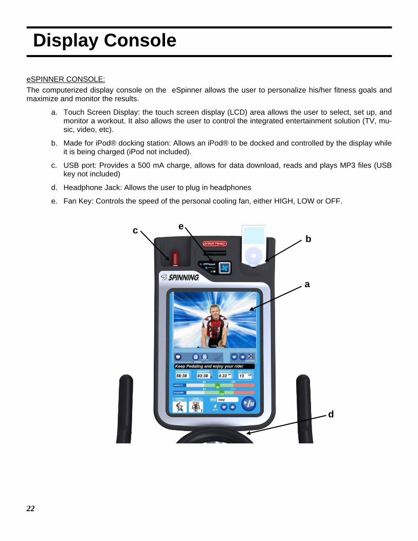
eSPINNER CONSOLE: The computerized display console on the eSpinner allows the user to personalize his/her fitness goals and maximize and monitor the results.
a. Touch Screen Display: the touch screen display (LCD) area allows the user to select, set up, and monitor a workout. It also allows the user to control the integrated entertainment solution (TV, mu-sic, video, etc).
b. Made for iPod® docking station: Allows an iPod® to be docked and controlled by the display while it is being charged (iPod not included).
c. USB port: Provides a 500 mA charge, allows for data download, reads and plays MP3 files (USB key not included)
d. Headphone Jack: Allows the user to plug in headphones
e. Fan Key: Controls the speed of the personal cooling fan, either HIGH, LOW or OFF.
e b
d
a
c
23
Display Console
WORKOUT OPTIONS SCREEN:
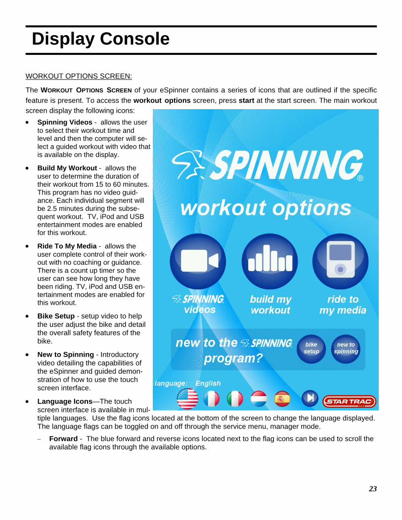
The WORKOUT OPTIONS SCREEN of your eSpinner contains a series of icons that are outlined if the specific feature is present. To access the workout options screen, press start at the start screen. The main workout screen display the following icons: • Spinning Videos - allows the user
to select their workout time and level and then the computer will se-lect a guided workout with video that is available on the display.
• Build My Workout - allows the user to determine the duration of their workout from 15 to 60 minutes. This program has no video guid-ance. Each individual segment will be 2.5 minutes during the subse-quent workout. TV, iPod and USB entertainment modes are enabled for this workout.
• Ride To My Media - allows the user complete control of their work-out with no coaching or guidance. There is a count up timer so the user can see how long they have been riding. TV, iPod and USB en-tertainment modes are enabled for this workout.
• Bike Setup - setup video to help the user adjust the bike and detail the overall safety features of the bike.
• New to Spinning - Introductory video detailing the capabilities of the eSpinner and guided demon-stration of how to use the touch screen interface.
• Language Icons—The touch screen interface is available in mul-tiple languages. Use the flag icons located at the bottom of the screen to change the language displayed. The language flags can be toggled on and off through the service menu, manager mode. − Forward - The blue forward and reverse icons located next to the flag icons can be used to scroll the
available flag icons through the available options.
24
Display Console
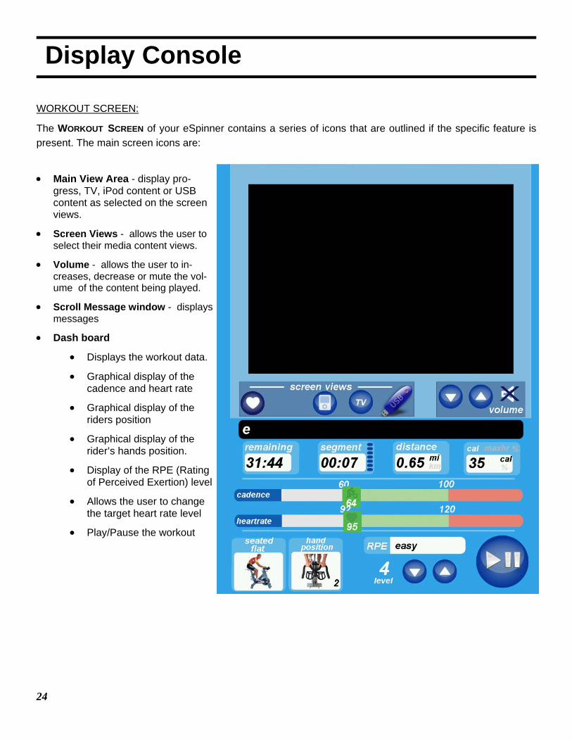
WORKOUT SCREEN:
The WORKOUT SCREEN of your eSpinner contains a series of icons that are outlined if the specific feature is present. The main screen icons are:
• Main View Area - display pro-
gress, TV, iPod content or USB content as selected on the screen views.
• Screen Views - allows the user to select their media content views.
• Volume - allows the user to in-creases, decrease or mute the vol-ume of the content being played.
• Scroll Message window - displays messages
• Dash board
• Displays the workout data.
• Graphical display of the cadence and heart rate
• Graphical display of the riders position
• Graphical display of the rider’s hands position.
• Display of the RPE (Rating of Perceived Exertion) level
• Allows the user to change the target heart rate level
• Play/Pause the workout
25
Bike Adjustments
Your Spinner® indoor cycling bike is easy to use. The bike allows the user full control over resistance by simply adjust-ing the brake pad. Typically, lower resistance levels enable you to pedal at a faster pace, placing increased demand on the cardiovascular system. Higher resistance levels will typically deliver a greater muscle/endurance workout at lower RPMs (Revolutions Per Minute). RPM parameters in the Spinning® program range from 60 to 110 RPM.
Additionally, the bike offers seat and handlebar adjustments, allowing the bike to be configured to each users comfort zone.
This section provides the instructions for making seat adjustments, handlebar adjustments, pedal strap adjustments, and for controlling resistance. Differences between models are noted where applicable.
PLEASE NOTE: In a club setting, we recommend each user to initially be properly fitted on the bike by a certi-fied Spinning® instructor.
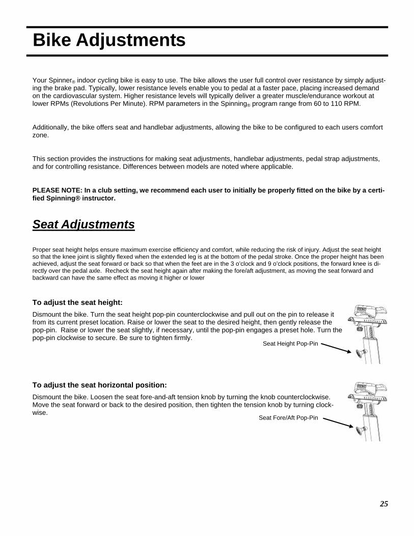
Seat Adjustments
Proper seat height helps ensure maximum exercise efficiency and comfort, while reducing the risk of injury. Adjust the seat height so that the knee joint is slightly flexed when the extended leg is at the bottom of the pedal stroke. Once the proper height has been achieved, adjust the seat forward or back so that when the feet are in the 3 o’clock and 9 o’clock positions, the forward knee is di-rectly over the pedal axle. Recheck the seat height again after making the fore/aft adjustment, as moving the seat forward and backward can have the same effect as moving it higher or lower
To adjust the seat height: Dismount the bike. Turn the seat height pop-pin counterclockwise and pull out on the pin to release it from its current preset location. Raise or lower the seat to the desired height, then gently release the pop-pin. Raise or lower the seat slightly, if necessary, until the pop-pin engages a preset hole. Turn the pop-pin clockwise to secure. Be sure to tighten firmly.
To adjust the seat horizontal position: Dismount the bike. Loosen the seat fore-and-aft tension knob by turning the knob counterclockwise. Move the seat forward or back to the desired position, then tighten the tension knob by turning clock-wise.
Seat Height Pop-Pin
Seat Fore/Aft Pop-Pin

26
Bike Adjustments
Handlebar Adjustments
Position the handlebar at the same height as your seat, or higher if you feel any discomfort in your back. All Spinner® indoor cycling bikes allow for adjustment of handlebar height.
To adjust the handlebar height: Turn the handlebar height pop-pin counterclockwise and pull out on the pin to release it from its current preset location. Raise or lower the handlebar to the desired height, then gently release the pop-pin. Raise or lower the handlebar slightly, if necessary, until the pop-pin engages a preset hole. Turn the pop-pin clockwise to secure.
Pedal Strap Adjustment
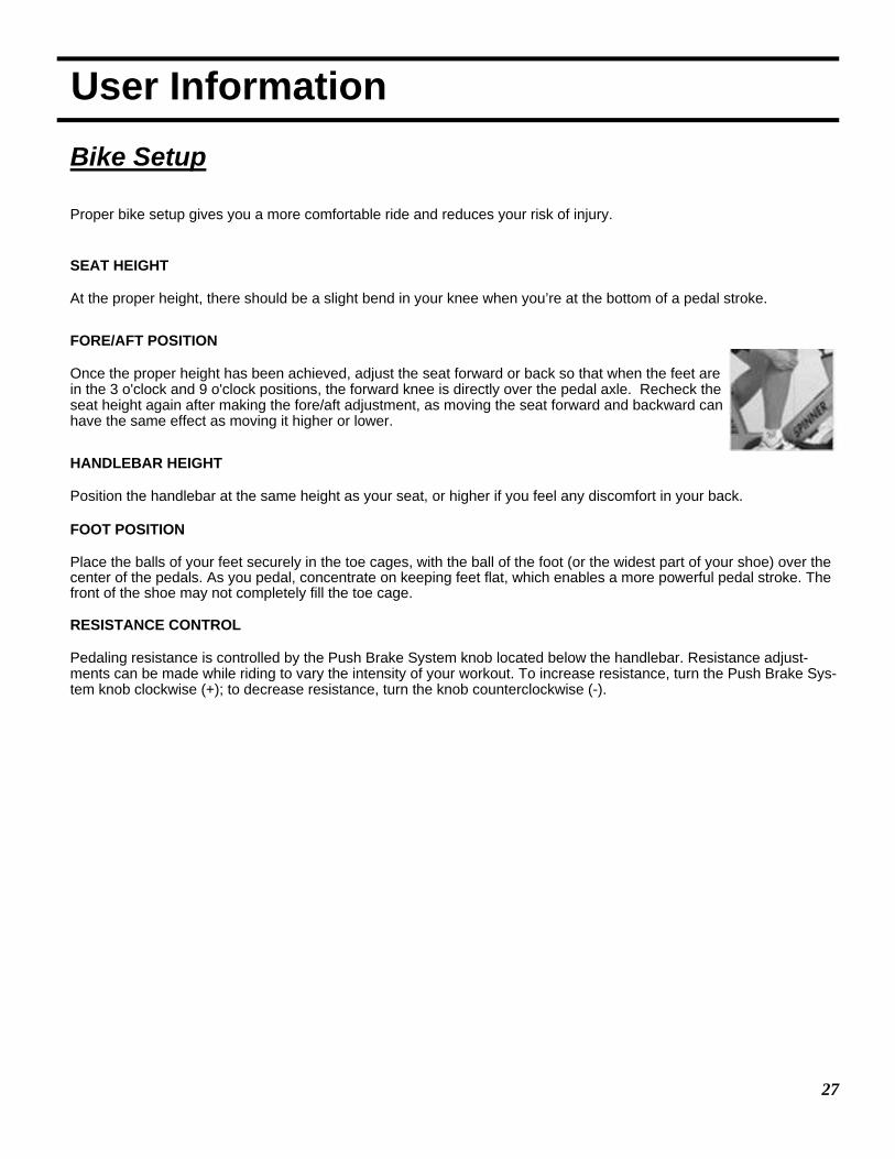
To adjust the pedal straps: Place the balls of your feet securely in the toe cages, with the ball of the foot (or the widest part of your shoe) over the center of the pedals. As you pedal, concentrate on keeping feet flat, which enables a more powerful pedal stroke. The front of the shoe may not completely fill the toe cage.
Note: The pedal straps should be adjusted to hold the foot snugly in the pedal.
Resistance Control
Pedaling resistance is controlled by the resistance knob. Resistance adjustments can be made while riding to vary the intensity of your workout. To increase resistance, turn the Push Brake Sys-tem knob clockwise (+); to decrease resistance, turn the knob counterclockwise (-).
NOTE: In case of emergency, you may press directly down on the Push Brake System knob to bring the flywheel to an abrupt stop.
Smart Release™ System
Allows the benefits of the direct drive system with a safety clutch to release the crank from the direct drive when a force is applied to the pedals.
Handlebar Height Pop-Pin
Tightening Clip
Resistance Knob
27
User Information
Bike Setup
Proper bike setup gives you a more comfortable ride and reduces your risk of injury.
SEAT HEIGHT At the proper height, there should be a slight bend in your knee when you’re at the bottom of a pedal stroke.
FORE/AFT POSITION Once the proper height has been achieved, adjust the seat forward or back so that when the feet are in the 3 o'clock and 9 o'clock positions, the forward knee is directly over the pedal axle. Recheck the seat height again after making the fore/aft adjustment, as moving the seat forward and backward can have the same effect as moving it higher or lower.
HANDLEBAR HEIGHT Position the handlebar at the same height as your seat, or higher if you feel any discomfort in your back. FOOT POSITION Place the balls of your feet securely in the toe cages, with the ball of the foot (or the widest part of your shoe) over the center of the pedals. As you pedal, concentrate on keeping feet flat, which enables a more powerful pedal stroke. The front of the shoe may not completely fill the toe cage. RESISTANCE CONTROL Pedaling resistance is controlled by the Push Brake System knob located below the handlebar. Resistance adjust-ments can be made while riding to vary the intensity of your workout. To increase resistance, turn the Push Brake Sys-tem knob clockwise (+); to decrease resistance, turn the knob counterclockwise (-).
28
User Information
Hand Positions
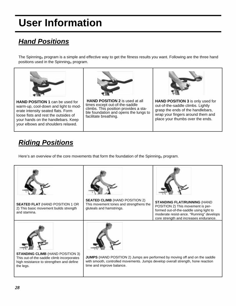
The Spinning® program is a simple and effective way to get the fitness results you want. Following are the three hand positions used in the Spinning® program.
Riding Positions Here’s an overview of the core movements that form the foundation of the Spinning® program.
HAND POSITION 1 can be used for warm-up, cool-down and light to mod-erate intensity seated flats. Form loose fists and rest the outsides of your hands on the handlebars. Keep your elbows and shoulders relaxed.
HAND POSITION 2 is used at all times except out-of-the-saddle climbs. This position provides a sta-ble foundation and opens the lungs to facilitate breathing.
HAND POSITION 3 is only used for out-of-the-saddle climbs. Lightly grasp the ends of the handlebars, wrap your fingers around them and place your thumbs over the ends.
SEATED FLAT (HAND POSITION 1 OR 2) This basic movement builds strength and stamina.
SEATED CLIMB (HAND POSITION 2) This movement tones and strengthens the gluteals and hamstrings.
STANDING FLAT/RUNNING (HAND POSITION 2) This movement is per-formed out-of-the-saddle using light to moderate resist-ance. “Running” develops core strength and increases endurance.
STANDING CLIMB (HAND POSITION 3) This out-of-the-saddle climb incorporates high resistance to strengthen and define the legs.
JUMPS (HAND POSITION 2) Jumps are performed by moving off and on the saddle with smooth, controlled movements. Jumps develop overall strength, hone reaction time and improve balance.
29
User Information
Stretching Stretching will help prevent injury and soreness. It keeps the lower back and leg muscles flexible, which enhances physical perform-ance and reduces strain. Below are some key stretches to incorporate at the beginning and end of your workout. You should stretch slowly to the point where mild discomfort is felt in the muscle being stretched. Practice deep breathing through the nose at all times. Do not bounce during the stretch, since this may result in injury. The following streches should be performed off the bike.
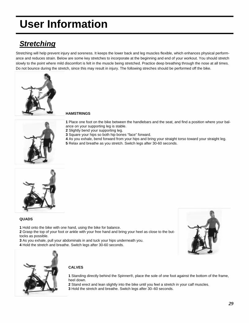
HAMSTRINGS 1 Place one foot on the bike between the handlebars and the seat, and find a position where your bal-ance on your supporting leg is stable. 2 Slightly bend your supporting leg. 3 Square your hips so both hip bones “face” forward. 4 As you exhale, bend forward from your hips and bring your straight torso toward your straight leg. 5 Relax and breathe as you stretch. Switch legs after 30-60 seconds.
QUADS 1 Hold onto the bike with one hand, using the bike for balance. 2 Grasp the top of your foot or ankle with your free hand and bring your heel as close to the but-tocks as possible. 3 As you exhale, pull your abdominals in and tuck your hips underneath you. 4 Hold the stretch and breathe. Switch legs after 30-60 seconds.
CALVES 1 Standing directly behind the Spinner®, place the sole of one foot against the bottom of the frame, heel down. 2 Stand erect and lean slightly into the bike until you feel a stretch in your calf muscles. 3 Hold the stretch and breathe. Switch legs after 30–60 seconds.
30
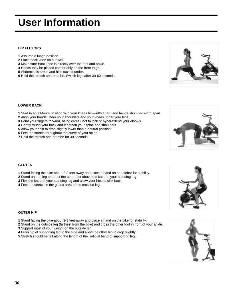
User Information HIP FLEXORS 1 Assume a lunge position. 2 Place back knee on a towel. 3 Make sure front knee is directly over the foot and ankle. 4 Hands may be placed comfortably on the front thigh. 5 Abdominals are in and hips tucked under. 6 Hold the stretch and breathe. Switch legs after 30-60 seconds.
LOWER BACK 1 Start in an all-fours position with your knees hip-width apart, and hands shoulder-width apart. 2 Align your hands under your shoulders and your knees under your hips. 3 Point your fingers forward, being careful not to lock or hyperextend your elbows. 4 Gently round your back and lengthen your spine and shoulders. 5 Allow your chin to drop slightly lower than a neutral position. 6 Feel the stretch throughout the curve of your spine. 7 Hold the stretch and breathe for 30 seconds. GLUTES 1 Stand facing the bike about 2-3 feet away and place a hand on handlebar for stability. 2 Stand on one leg and rest the other foot above the knee of your standing leg. 3 Flex the knee of your standing leg and allow your hips to sink back. 4 Feel the stretch in the glutes area of the crossed leg.
OUTER HIP 1 Stand facing the bike about 2-3 feet away and place a hand on the bike for stability. 2 Stand on the outside leg (farthest from the bike) and cross the other foot in front of your ankle. 3 Support most of your weight on the outside leg. 4 Push hip of supporting leg to the side and allow the other hip to drop slightly. 5 Stretch should be felt along the length of the iliotibial band of supporting leg.
31
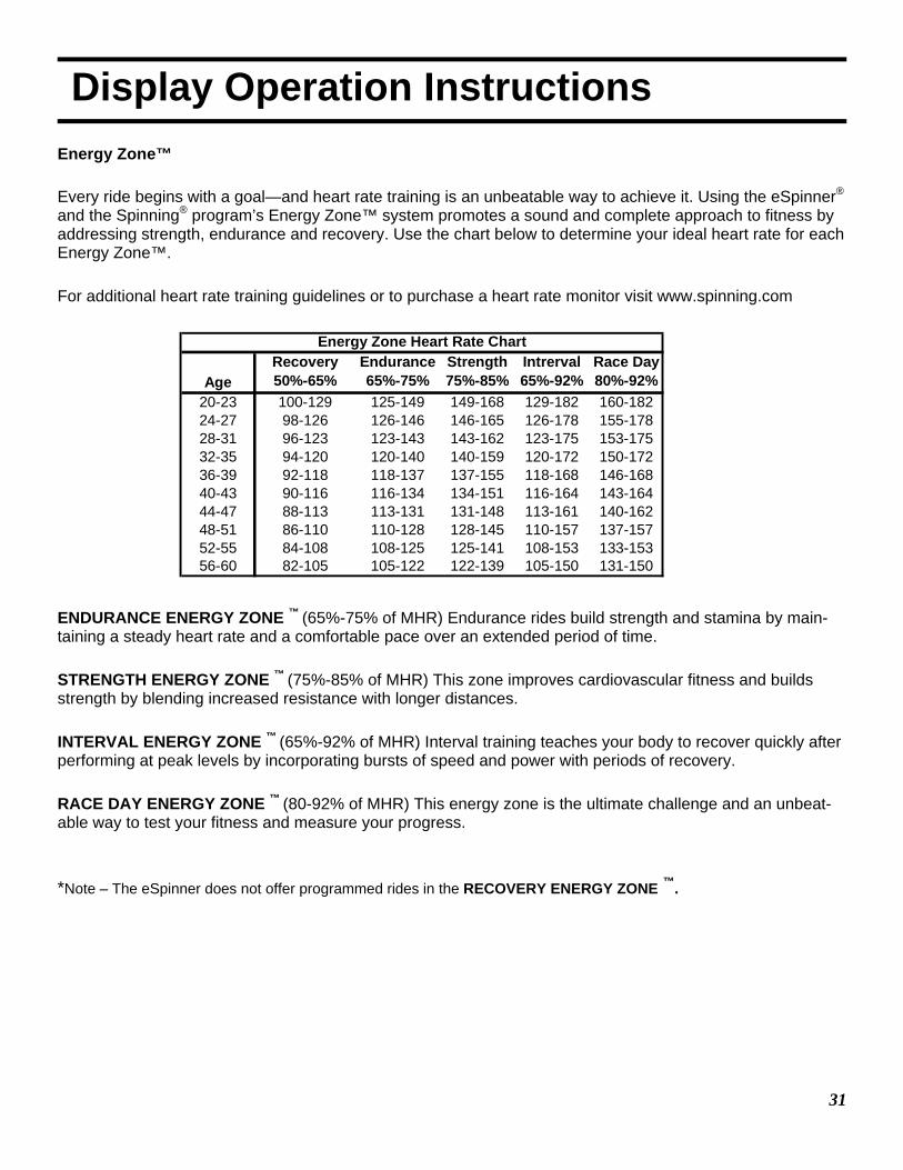
Display Operation Instructions Energy Zone™ Every ride begins with a goal—and heart rate training is an unbeatable way to achieve it. Using the eSpinner® and the Spinning® program’s Energy Zone™ system promotes a sound and complete approach to fitness by addressing strength, endurance and recovery. Use the chart below to determine your ideal heart rate for each Energy Zone™. For additional heart rate training guidelines or to purchase a heart rate monitor visit www.spinning.com ENDURANCE ENERGY ZONE ™ (65%-75% of MHR) Endurance rides build strength and stamina by main-taining a steady heart rate and a comfortable pace over an extended period of time. STRENGTH ENERGY ZONE ™ (75%-85% of MHR) This zone improves cardiovascular fitness and builds strength by blending increased resistance with longer distances. INTERVAL ENERGY ZONE ™ (65%-92% of MHR) Interval training teaches your body to recover quickly after performing at peak levels by incorporating bursts of speed and power with periods of recovery. RACE DAY ENERGY ZONE ™ (80-92% of MHR) This energy zone is the ultimate challenge and an unbeat-able way to test your fitness and measure your progress. *Note – The eSpinner does not offer programmed rides in the RECOVERY ENERGY ZONE ™.
AgeRecovery50%-65%
Endurance65%-75%
Strength75%-85%
Intrerval65%-92%
Race Day80%-92%
20-23 100-129 125-149 149-168 129-182 160-18224-27 98-126 126-146 146-165 126-178 155-17828-31 96-123 123-143 143-162 123-175 153-17532-35 94-120 120-140 140-159 120-172 150-17236-39 92-118 118-137 137-155 118-168 146-16840-43 90-116 116-134 134-151 116-164 143-16444-47 88-113 113-131 131-148 113-161 140-16248-51 86-110 110-128 128-145 110-157 137-15752-55 84-108 108-125 125-141 108-153 133-15356-60 82-105 105-122 122-139 105-150 131-150
Energy Zone Heart Rate Chart

32
Display Operation Instructions RIDING THE eSPINNER: From the main menu screen there are three (3) options to choose your workout.
• Spinning Videos - allows the user to workout to a guided video workout with audio and video that is dis-played on the screen along with the rider dashboard.
• Build My Workout - allows the user to select a Spinning workout of their choice. This workout option does not have video guidance. TV, iPod and USB entertainment modes are enabled for this workout.
• Ride To My Media - allows the user complete control of their workout with no coaching or guidance. TV, iPod and USB entertainment modes are enabled for this workout.
Workout Options:
By touching the small yellow “i” next to each description you can get a longer explanation of each energy zone. Close the description by pressing the “x
33
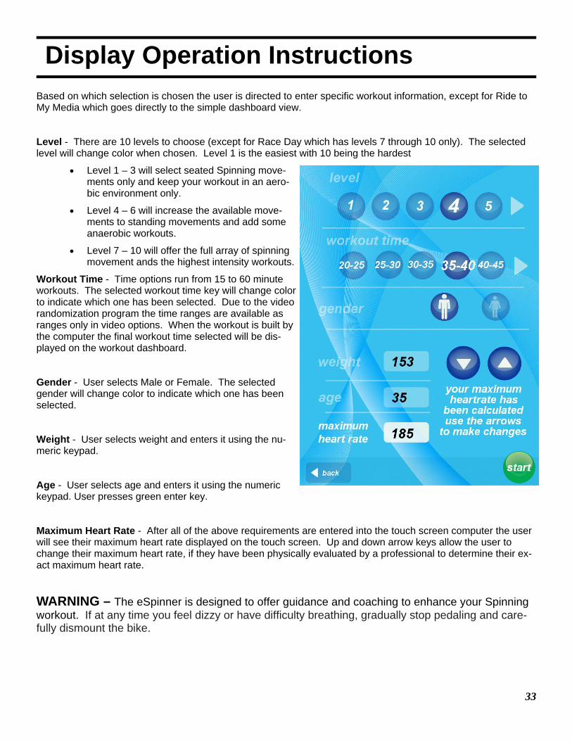
Display Operation Instructions Based on which selection is chosen the user is directed to enter specific workout information, except for Ride to My Media which goes directly to the simple dashboard view.
Level - There are 10 levels to choose (except for Race Day which has levels 7 through 10 only). The selected level will change color when chosen. Level 1 is the easiest with 10 being the hardest
• Level 1 – 3 will select seated Spinning move-ments only and keep your workout in an aero-bic environment only.
• Level 4 – 6 will increase the available move-ments to standing movements and add some anaerobic workouts.
• Level 7 – 10 will offer the full array of spinning movement ands the highest intensity workouts.
Workout Time - Time options run from 15 to 60 minute workouts. The selected workout time key will change color to indicate which one has been selected. Due to the video randomization program the time ranges are available as ranges only in video options. When the workout is built by the computer the final workout time selected will be dis-played on the workout dashboard.
Gender - User selects Male or Female. The selected gender will change color to indicate which one has been selected.
Weight - User selects weight and enters it using the nu-meric keypad.
Age - User selects age and enters it using the numeric keypad. User presses green enter key.
Maximum Heart Rate - After all of the above requirements are entered into the touch screen computer the user will see their maximum heart rate displayed on the touch screen. Up and down arrow keys allow the user to change their maximum heart rate, if they have been physically evaluated by a professional to determine their ex-act maximum heart rate.
WARNING – The eSpinner is designed to offer guidance and coaching to enhance your Spinning workout. If at any time you feel dizzy or have difficulty breathing, gradually stop pedaling and care-fully dismount the bike.
34
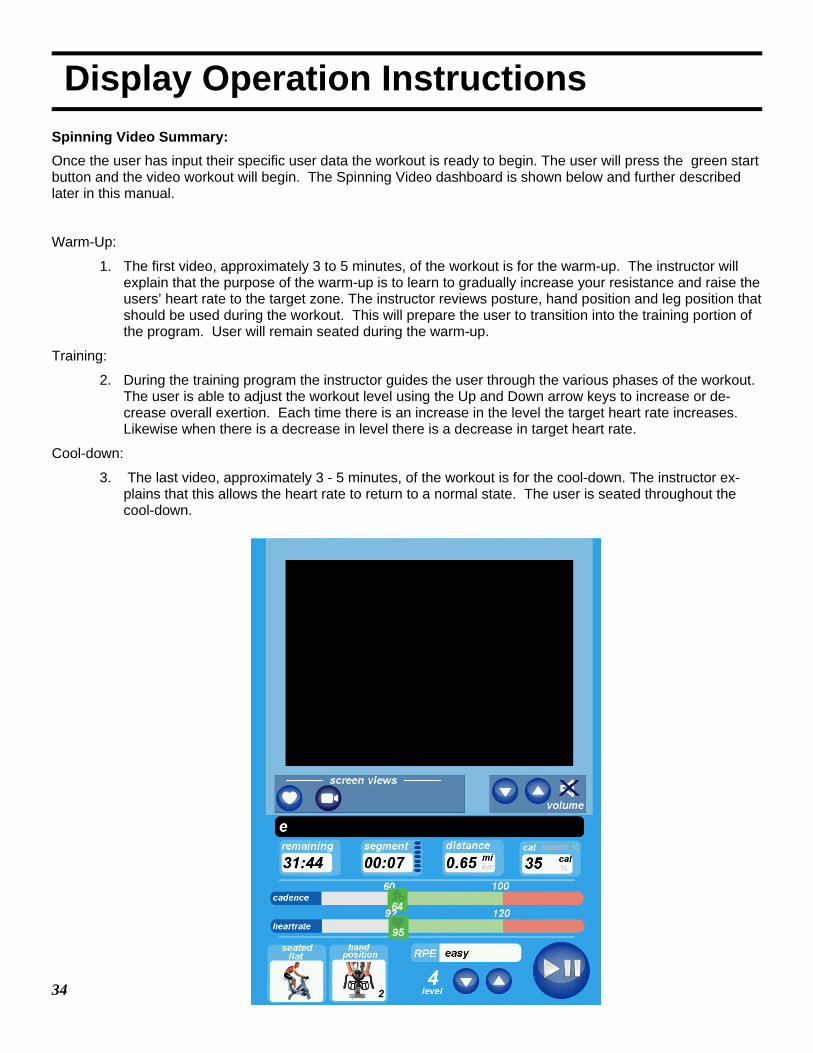
Display Operation Instructions Spinning Video Summary: Once the user has input their specific user data the workout is ready to begin. The user will press the green start button and the video workout will begin. The Spinning Video dashboard is shown below and further described later in this manual.
Warm-Up:
1. The first video, approximately 3 to 5 minutes, of the workout is for the warm-up. The instructor will explain that the purpose of the warm-up is to learn to gradually increase your resistance and raise the users’ heart rate to the target zone. The instructor reviews posture, hand position and leg position that should be used during the workout. This will prepare the user to transition into the training portion of the program. User will remain seated during the warm-up.
Training:
2. During the training program the instructor guides the user through the various phases of the workout. The user is able to adjust the workout level using the Up and Down arrow keys to increase or de-crease overall exertion. Each time there is an increase in the level the target heart rate increases. Likewise when there is a decrease in level there is a decrease in target heart rate.
Cool-down:
3. The last video, approximately 3 - 5 minutes, of the workout is for the cool-down. The instructor ex-plains that this allows the heart rate to return to a normal state. The user is seated throughout the cool-down.

35
Display Operation Instructions Build My Workout: Press Green Start Button and the program will begin. TV, iPod and USB entertainment modes are enabled for this workout.
Warm-Up:
1. The first 5 minutes of the workout are for the warm-up. User should review hand placement and leg position that should be used during the workout. This will prepare the user to transition into the train-ing portion of the program. User will remain seated during the warm-up.
Training:
2. During the workout the user is able to adjust the workout level using the Up and Down arrow keys to increase or decrease overall exertion. Each time there is an increase of decrease in level the target heartrate adjusts accordingly. Additionally, the computer also rebuilds the ride based on the available workouts if the users chooses a workout level that is substantially different than the level that started the workout. For example if the user starts in level 7 and reduces the workout to level 3, the com-puter will recalculate the future movements and remove all the standing movements from the workout.
Cool-down:
3. The last 5 minutes of the workout are for the cool-down. This phase allows the heart rate to return to normal state. The user is seated throughout the cool-down.
36
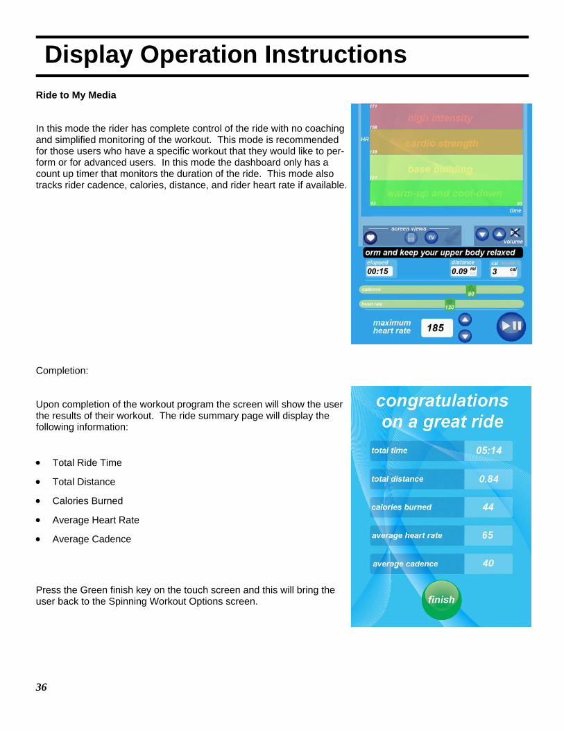
Display Operation Instructions Ride to My Media
In this mode the rider has complete control of the ride with no coaching and simplified monitoring of the workout. This mode is recommended for those users who have a specific workout that they would like to per-form or for advanced users. In this mode the dashboard only has a count up timer that monitors the duration of the ride. This mode also tracks rider cadence, calories, distance, and rider heart rate if available.
Completion:
Upon completion of the workout program the screen will show the user the results of their workout. The ride summary page will display the following information:
• Total Ride Time
• Total Distance
• Calories Burned
• Average Heart Rate
• Average Cadence
Press the Green finish key on the touch screen and this will bring the user back to the Spinning Workout Options screen.
New pic-ture needed
37
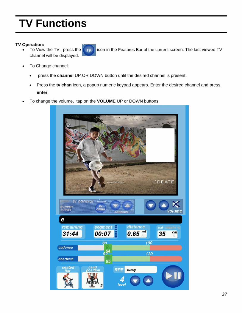
TV Functions TV Operation:
• To View the TV, press the icon in the Features Bar of the current screen. The last viewed TV channel will be displayed.
• To Change channel:
• press the channel UP OR DOWN button until the desired channel is present.
• Press the tv chan icon, a popup numeric keypad appears. Enter the desired channel and press
enter.
• To change the volume, tap on the VOLUME UP or DOWN buttons.
38
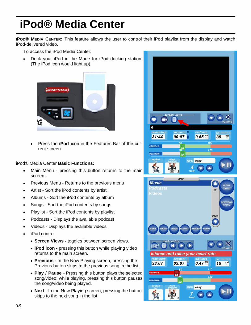
iPod® Media Center IPOD® MEDIA CENTER: This feature allows the user to control their iPod playlist from the display and watch iPod-delivered video.
To access the iPod Media Center: • Dock your iPod in the Made for iPod docking station.
(The iPod icon would light up).
• Press the iPod icon in the Features Bar of the cur-
rent screen.
iPod® Media Center Basic Functions: • Main Menu - pressing this button returns to the main
screen. • Previous Menu - Returns to the previous menu • Artist - Sort the iPod contents by artist • Albums - Sort the iPod contents by album • Songs - Sort the iPod contents by songs • Playlist - Sort the iPod contents by playlist • Podcasts - Displays the available podcast • Videos - Displays the available videos • iPod control
• Screen Views - toggles between screen views. • iPod icon - pressing this button while playing video
returns to the main screen. • Previous - In the Now Playing screen, pressing the
Previous button skips to the previous song in the list. • Play / Pause - Pressing this button plays the selected
song/video; while playing, pressing this button pauses the song/video being played.
• Next - In the Now Playing screen, pressing the button skips to the next song in the list.
39
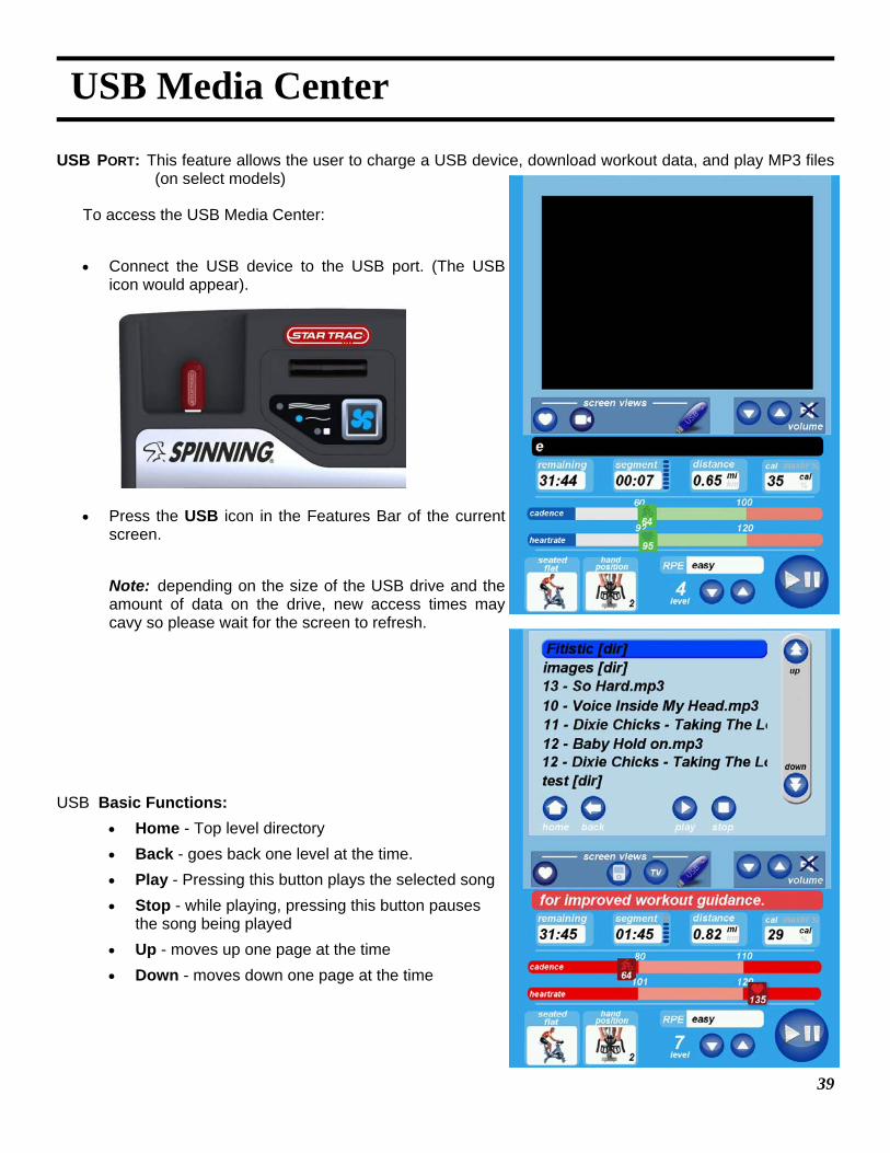
USB Media Center
USB PORT: This feature allows the user to charge a USB device, download workout data, and play MP3 files (on select models)
To access the USB Media Center: • Connect the USB device to the USB port. (The USB
icon would appear).
• Press the USB icon in the Features Bar of the current
screen. Note: depending on the size of the USB drive and the
amount of data on the drive, new access times may cavy so please wait for the screen to refresh.
USB Basic Functions: • Home - Top level directory • Back - goes back one level at the time. • Play - Pressing this button plays the selected song • Stop - while playing, pressing this button pauses
the song being played • Up - moves up one page at the time • Down - moves down one page at the time
40
Additional Features USING PERSONAL FAN
Your STAR TRAC E-SPINNER is equipped with built-in personal fan to increase your comfort during a work-out. You can control the fan speed during your workout.
To operate the personal fan:
• Press the key, as necessary, to cycle the personal fans from OFF to HIGH to LOW to OFF. An LED indicator lights to show the currently selected fan speed.
• The fans remains set at the set speed if you pause your program.
HEART RATE MONITORING
Heart rate monitoring allows you to determine if your workout is too challenging or not challenging enough. You may use a heart rate strap (not provided with the equipment).
NOTE: The Heart Rate monitor is not a medical test, nor is it designed as a medical test. It is simply a guide to target heart rate training. Please consult with your physician prior to engaging in any strenuous physical activity.
IMPORTANT: The manufacturer does not warranty the heart rate system performance on this product, as the heart rate system performance varies, based on a user's physiology, fitness level, age, method of use and other factors. Furthermore, the heart rate system is not for medical use.
Chest Strap Heart Rate Monitoring
You may use the heart rate strap to automatically check your heart rate. Just follow these steps: • Before beginning your workout, or during a pause, moisten the back of the transmitter on the heart
rate strap (not included). Place the strap snugly around your chest with the transmitter resting directly over your sternum.
• When your heart rate has been acquired, the Main Screen displays a permanent Heart Rate icon and your heart rate in beats-per-minute (BPM).
• Remove the heart rate strap, if you wish to remove your heart rate reading from the display.
NOTE: The performance of the transmitter may be affected by body types, body oils, metal in clothing, and outside electrical interference. Always be sure that the transmitter and skin are in good contact. Avoid operating other electrical equipment near your treadmill when you use the heart rate strap.
41
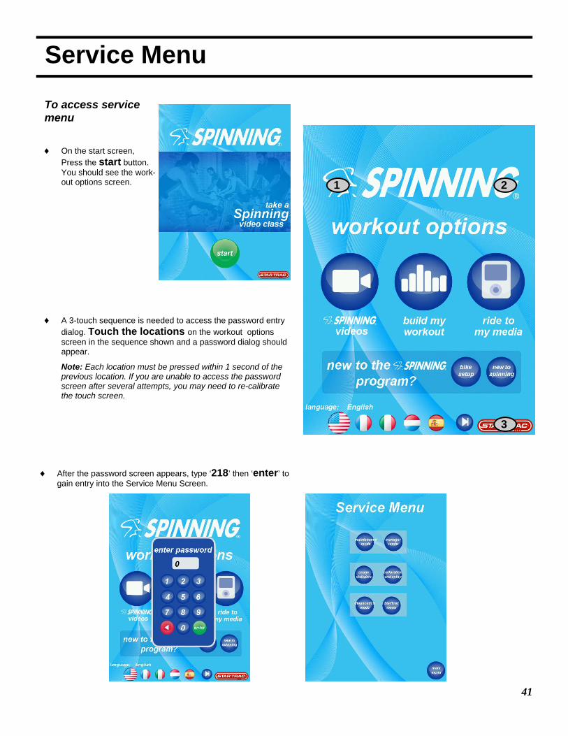
Service Menu
3
1 2
To access service menu
♦ On the start screen, Press the start button. You should see the work-out options screen.
♦ A 3-touch sequence is needed to access the password entry dialog. Touch the locations on the workout options screen in the sequence shown and a password dialog should appear.
Note: Each location must be pressed within 1 second of the previous location. If you are unable to access the password screen after several attempts, you may need to re-calibrate the touch screen.
♦ After the password screen appears, type ‘218’ then ‘enter’ to gain entry into the Service Menu Screen.

42
♦ Maintenance Mode -
• Update code
• Set Time
♦ User Statistics - displays the user static's information (number of times a given program has been accessed).
♦ Diagnostics mode - changes the fan option between ON and OFF
♦ Managers Mode -
• Club ID menu
• Update images
• Disable languages
• Change password
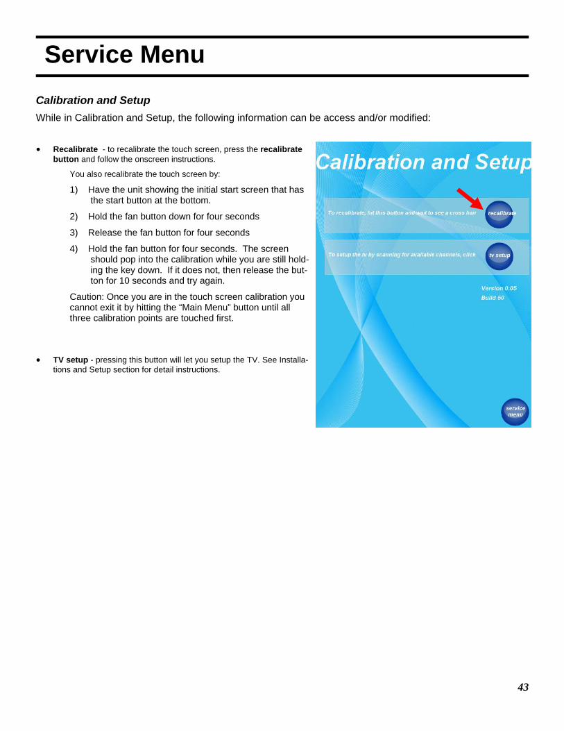
♦ Calibration and setup -
• Recalibrate (touch-screen)
• TV setup
Service Menu
While in Service Menu, the following information can be access and/or modified:
43
• Recalibrate - to recalibrate the touch screen, press the recalibrate button and follow the onscreen instructions.
You also recalibrate the touch screen by:
1) Have the unit showing the initial start screen that has the start button at the bottom.
2) Hold the fan button down for four seconds
3) Release the fan button for four seconds
4) Hold the fan button for four seconds. The screen should pop into the calibration while you are still hold-ing the key down. If it does not, then release the but-ton for 10 seconds and try again.
Caution: Once you are in the touch screen calibration you cannot exit it by hitting the “Main Menu” button until all three calibration points are touched first.
• TV setup - pressing this button will let you setup the TV. See Installa-tions and Setup section for detail instructions.
Service Menu
Calibration and Setup While in Calibration and Setup, the following information can be access and/or modified:
44
Maintenance
This section provides the procedures to maintain the Spinner® indoor cycling bikes in serviceable condition. Differences between models are noted where applicable.
Moving and Leveling To move the bike to a new location: Lift the bike from the rear and use the front wheels (located on the front leg, below the han-dlebar) to roll the bike from one location to another.
To level the bike: Use the four leveling adjusters (located on the underside of the front and rear legs) to compensate for uneven floor surfaces.
Preventive Maintenance Perform regular scheduled preventive maintenance procedures to maintain your Spinner® indoor cycling bike in serviceable condi-tion.
TOOLS Tools required for service and maintenance of your Spinner® indoor cycling bike are listed below.
Available at local bike or fitness-related stores.
Daily Maintenance The service life of your Spinner® indoor cycling bike will be determined by how consistently you perform the daily maintenance pro-cedures. Dry the Spinner® indoor cycling bike after each use to remove sweat and moisture. It is best to use a liquid non-abrasive cleaner and water solution.
Wipe Down / Cleaning To prevent the build-up of rust and other forms of corrosion, wipe down the bike at the end of each day (or preferably at the end of each class). Raise all posts to the highest setting to expose moisture. Using an absorbent cloth, focus on all areas that perspiration can settle. Give particular attention to the following areas:
Handlebar Seat / adjustable slide for the seat Flywheel
Back leg assembly Chain guard Brake knob and bolt assembly
Pop-pins Leveling feet
NOTE: Never use abrasive cleaning liquids or petroleum-based solvents when wiping down the bike.
NOTE: Release all tension from the resistance knob after each use to allow for perspiration to evaporate. If bikes are used in a class setting, the instructor may direct class participants to release all tension for the resistance knob after each use.
Tool Purpose
Pedal Wrench, 15mm* Remove and install pedals.
Shimano-compatible Bottom Bracket Tool* Remove, install and adjust the bottom bracket. (Spinner® V)
Cotterless Crank Puller* Remove crank.
Metric Allen Wrench Set and Metric Socket, 2mm ~ 6mm Install and adjust leg bolts, chain tensioner, brake pad and crank bolts.
Crescent (adjustable) Wrench Adjust chain tension.
Torque Wrench Adjust crank arm.
45
Preventive Maintenance Inspection / Adjustments Inspect major moving parts that require constant proper torque. Loose or misadjusted parts can result in personal injury or damage to the bike. Check the following parts for security and/or proper torque. Crank arms : The crank arms should be re-torqued after the first 10 hours of use and every 100 hours of operation, thereafter. The
crank arm to the bottom bracket torque is 30 lbs-ft (± 3 lbs-ft). Pedals: Use a pedal wrench. Verify that the pedal is not cross-threaded. IMPORTANT: If your facility allows members to interchange pedals, it is critical that the pedals are checked after each class
to prevent damage, which may lead to injuries if ignored. Water bottle: Tighten down assembly screws. NOTE: Water bottle cages are easily damaged when oversized bottles are forced to fit within the bottle cage. Checking and
tightening the screws will help prevent damage.
Weekly Maintenance Weekly maintenance should focus on the overall performance of the Spinner® indoor cycling bike. During these inspections, look for vibration and possible loose assemblies.
Have an experienced rider ride each bike to identify and help diagnose any vibration, noises, and any "unusual" feeling from the drive chain. Either faulty flywheel alignment or a loose chain can cause vibration.
• Check for proper flywheel alignment. Torque flywheel nuts as necessary.
• Remove chain guard and check for loose chain. Adjust chain as necessary (refer to "Chain Adjustment" on pages 23-24).
• Inspect The Bottom Bracket Assembly (BBA). The BBA will come loose periodically and require tightening. Loose play (left and right motion) indicates the BBA needs adjusting.
Inspect each bike for loose assemblies, parts, bolts and nuts. Give particular attention to the following:
• Tighten all frame base hardware.
• Tighten all pull pin handles.
• Tighten seat hardware.
• Tighten pedal toe clip / toe straps.
• Inspect and tighten tension knob assembly.
Monthly Maintenance The monthly maintenance check should be a comprehensive inspection of the overall frame and main assembly components of the Spinner® indoor cycling bike.
• Inspect the frame and main assembly components for rust or corrosion. Tilt the bike or place in an upside down position to lo-cate areas where rust and corrosion may develop. Use a small, wire brush to remove rust build-up in small crevasses, such as leveling feet, pop pin handles and other bolt assemblies. Give particular attention to the following areas:
Leveling feet Pop pin handles
• Inspect all wear items for adjustments or possible part replacement. Give particular attention to the following:
• Inspect brake pad for wear. Excessive wear, such as glazing or leather separation, indicates replacement is required.
• Inspect seat pad for wear. Rips, tears or excessive movement indicates replacement is required.
• Inspect pedals for play. Excessive movement of pedals indicates replacement is required.
46
Preventive Maintenance Chain Tension Adjustment The chain on your bike has been factory set and lubricated. It should not require adjustment initially. Over time, however, you may need to adjust the tension.
CAUTION: Improper chain adjustment will cause premature wear and may void the warranty.
To adjust chain on eSpinner®:
Figure 1
1. Using a 3mm Allen Wrench, remove the four screws supporting the plastic chain guard shroud. (Figures 1)
2. Using a 16mm or 5/8” socket and socket wrench, loosen the axle nuts on both sides of the flywheel.
3. Using a 10mm open end wrench, loosen the lock nuts on the chain adjustment screws.
4. To tighten the chain, turn the adjustment screw in a clockwise rota-tion equally on both sides using the 10mm open end wrench.
5. To loosen the chain, turn the adjustment screws on both sides counter-clockwise using a 10mm open end wrench.
6. While adjusting the chain tension, work on both sides of the fly-wheel. Adjust the angle of the flywheel so it is straight front to rear and evenly spaced within the frame side to side. (Figure 2 )
7. Align the chain so it runs straight on both of the sprockets.
8. Adjust the angle of the flywheel by adjusting the adjustment screws on both sides of the flywheel. Test by slowly rotating the pedals.
Note:
• If the chain is stretched beyond adjustment, the replace-ment of the chain is recommended. Proceed to “Chain Replacement” for further instructions.
• When alignment is at the optimal adjustment, the chain will run smoother and quieter.
9. Tighten the adjustment lock nuts and axle nuts on both sides.
10. Install the chain guard shroud and re-test the bike.
Axle Nuts
Adjustment Screws
Figure 2 Lock Nuts
47
Preventive Maintenance Clutch Adjustment The chain on your bike has been factory set and lubricated. It should not require adjustment initially. Over time, however, you may need to adjust the tension.
CAUTION: Improper chain adjustment will cause premature wear and may void the warranty.
To adjust chain on eSpinner®:
1. Using a 3mm Allen Wrench, remove the three screws supporting the plastic chain guard shroud.
2. Using a 3mm Allen Wrench, remove the four screws supporting the COG guard cover. (Figure 3)
3. If the torque is not 45 ~ 50 ft-lbs. using a 5 mm Allen Wrench, give each of the set screws a little clockwise turn. A “little turn” is about 10 degrees. (Figure 3 & 4)
Note:
Be sure and turn all 5 set screws so they have equal pressure to obtain the proper adjustment. Recheck the torque for differ-ent positions around the clutch. If it is still not 45 ~ 50 ft-lbs, repeat the procedure.
The goal is to make all the set screws have the same pres-sure on the clutch.
4. Test the clutch system for proper operation for normal riding use. Observe all safety practices.
COG Cover
Figure 3
Set Screws
Figure 5
Figure 4
48
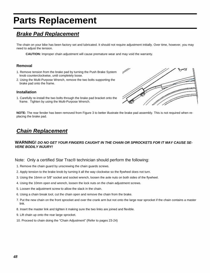
Parts Replacement Brake Pad Replacement The chain on your bike has been factory set and lubricated. It should not require adjustment initially. Over time, however, you may need to adjust the tension.
CAUTION: Improper chain adjustment will cause premature wear and may void the warranty.
Removal 1. Remove tension from the brake pad by turning the Push Brake System
knob counterclockwise, until completely loose. 2. Using the Multi-Purpose Wrench, remove the two bolts supporting the
brake pad onto the frame. Installation 1. Carefully re-install the two bolts through the brake pad bracket onto the
frame. Tighten by using the Multi-Purpose Wrench.
NOTE: The rear fender has been removed from Figure 3 to better illustrate the brake pad assembly. This is not required when re-placing the brake pad.
Chain Replacement
WARNING! DO NO GET YOUR FINGERS CAUGHT IN THE CHAIN OR SPROCKETS FOR IT MAY CAUSE SE-VERE BODILY INJURY! Note: Only a certified Star Trac® technician should perform the following: 1. Remove the chain guard by unscrewing the chain guards screws.
2. Apply tension to the brake knob by turning it all the way clockwise so the flywheel does not turn.
3. Using the 16mm or 5/8” socket and socket wrench, loosen the axle nuts on both sides of the flywheel.
4. Using the 10mm open end wrench, loosen the lock nuts on the chain adjustment screws.
5. Loosen the adjustment screw to allow the slack in the chain.
6. Using a chain break tool, cut the chain open and remove the chain from the brake.
7. Put the new chain on the front sprocket and over the crank arm but not onto the large rear sprocket if the chain contains a master link.
8. Insert the master link and tighten it making sure the two links are joined and flexible.
9. Lift chain up onto the rear large sprocket.
10. Proceed to chain doing the “Chain Adjustment” (Refer to pages 23-24)

49
Trouble Shooting All Embedded Display Products perform a self-test at the beginning of power up. If a problem is detected, a message displays before or after the workout, depending on the nature of the problem. Star Trac recommends that you refer your questions about your STAR TRAC PRODUCTS operation and suspected malfunctions to Star Trac’s Service Hotline at (800) 503-1221, or USA 1-714-669-1660.

50 DOC 620-7850 Rev A, February 2009
Star Trac 14410 Myford Road
Irvine, CA 92606 USA Email: [email protected]