Embed Size (px)
Citation preview

surface systemsStyled & Durable
surface systems
INSTALLATION GUIDE
GLASBORD® | DESIGNS | VARIETEX® | KEMPLY®
wall, ceiling and laminated panel installation
TOPICSGeneral Information 3Safety Precautions, Supplies, Equipment and Storage Information
Installation Preparation 4Wall Preparation, Choose an Adhesive, Environmental Considerations
Pre-Installation Planning 6FRP with Performance and Presence
Basic FRP Installation Steps 6
Cutting Instructions 6
Attaching to Wall 7Adhesive, Spacing, Panel Sequence, Panel Finishing
Seam Treatment Options 8Moldings, Color Coordinating Caulk, Fasteners, Seam Sealant
Specialty Installations 13Ceiling Panels, Car Washes, Laminated Panels
DISCLAIMER PLEASE READ ALL INSTRUCTIONS BEFORE BEGINNING INSTALLATIONThese guidelines are provided in good faith to help prevent installation problems caused by common errors. The manufacturer and/or distributor of the product bears no responsibility for installation actions taken or not taken. There are many nuances of installation that are assumed to be general construction knowledge to an experienced installer; such nuances are not included in these instructions. Rather, these installation guidelines are strictly recommendations and are not intended to serve as a step-by-step, foolproof installation checklist. Selection of an experienced FRP installer is the sole responsibility of the project owner and architect. Crane Composites does not accept any responsibility for job failure resulting from or associated with improper job site environmental conditions.
FACTORY MUTUAL APPROVAL Fire-X Glasbord (FXE and FSFM) is the only fiberglass reinforced interior wall and ceiling panel that is accepted under Factory Mutual Research approved FRP, Plastic Interior Finish Materials when installed in accordance with Factory Mutual Research Approval Standard 4880. This information is available at www.approvalguide.com and www.FRP.com/FMApproved.pdf.
NOTE: Please contact your local FM Global Representative to provide a field exemption of alternative methods of installation.
installation guide
GENERAL INFORMATION Safety Information WHEN CUTTING OR DRILLING, ALWAYS WEAR PROTECTIVE GLASSES OR GOGGLES AND A FACE MASK WHICH COVERS THE FACE AND MOUTH. Itching due to glass fibers may be avoided by the use of barrier creams on exposed skin areas. Hearing protection is also recommended.
Supplies and EquipmentSupplies will vary depending on wall substrate, adhesive choice and seam treatment selection.
STANDARD FRP TOOLS NEEDED• Crane Composites Laminate Roller (Part # R50ROLLER)• Crane Composites V-notched Trowel 3/16�� x 1/4�� x 5/16�� (Part # R50TROWEL)• Circular saw with fine tooth carbide tipped saw blade• Swivel-head 18 gauge shears • Drywall Roto-Zip®• Jig-Saw• Flat edge finishing tool (putty knife or equivalent)
MATERIALS NEEDED• Crane Composites FRP Panels• Adhesive - Crane Advanced Polymer Adhesive (R53829) or Crane Fast Grab Adhesive (R53828)
Refer to page 5 for assistance in selecting the appropriate adhesive• Soap and water for clean-up (Latex or Polymer adhesives)• Saw horses• Plywood larger than panels• Dry, lint free rags• Sandpaper or Paper Tiger® Wallpaper Removal Tool for roughing up wall• Tape measure• Utility knife• Six-penny finishing nails• Carbide tipped laminate cutter• IMPORTANT NOTE: If installation room has high humidity (65% or higher) then a portable low-cost dehumidifier unit is suggested.
SEAM TREATMENT • Moldings• Color Coordinating Caulk• Seam Sealant (cleanroom only)
• Cleanroom Wall System Seam Sealant - 7555 Urethane Sealant (R53827)• Applicator - Pneumatic Dual Chamber Applicator Gun (R50CAULKGUN) • 400ml Static Mixing Tips - 3/8�� x 11�� x 24 EL• Finishing Kit - Inline Seam and Radial Seam Finishers for seam smoothing (R50SEAM-KIT)• Panel Tape - 1�� by 144 yds (R53522)• Solvent for clean-up (IPA, acetone)• Protective gloves needed when using seam sealant
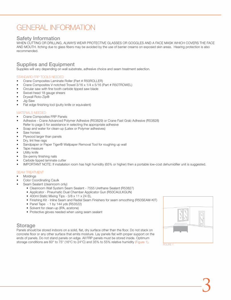
StoragePanels should be stored indoors on a solid, flat, dry surface other than the floor. Do not stack on concrete floor or any other surface that emits moisture. Lay panels flat with proper support on the ends of panels. Do not stand panels on edge. All FRP panels must be stored inside. Optimum storage conditions are 60° to 75° (16°C to 24°C) and 35% to 55% relative humidity (Figure 1).
FIGURE 1
3
INSTALLATION PREPARATIONPre-ConditioningBefore beginning the installation, the installer must determine that the environment of the jobsite meets or exceeds all requirements specified in the installation guide. Prior to installing, remove the packaging and allow the panels to acclimate to the room temperature and humidity for 24 hours. Acclimation temperature range should be 60°F to 75°F (16°C to 24°C) and relative humidity should be 35% to 55%. Ideally, both the room temperature and humidity during acclimation and installation should be the same as the final operating conditions.
Installation ConditionsInstallation should not begin until building is enclosed (windows and doors are installed), permanent heating and cooling equipment is in operation, and residual moisture from plaster, concrete, or terrazzo work has dissipated. Installation temperature range should be 60°F to 75°F (16°C to 24°C) and relative humidity range should be 35% to 55%.
Wall PreparationEvery attempt is made to inspect panels for cosmetic and physical abnormalities prior to shipment, however, all panels should be inspected for any defects prior to installation. The installer assumes all responsibility for full inspection of product before installation. If panels are not acceptable, contact your Customer Service Representative (CSR) immediately. Do not install panels of unacceptable or questionable quality. Crane Composites, Inc. will not be responsible for installation or removal costs of unacceptable panels. Walls should be flat and even. Remove high spots and fill in low spots prior to beginning installation. Remove any foreign matter that may interfere with the adhesive bond. The wall substrate must be dry and free from dirt, dust, and grease. Installation over uneven surfaces will result in little or no adhesion to the wall substrate, therefore bubbling due to air pockets will form behind the panel.
PAINTED OR PRIMED SURFACESPainted surfaces will not allow solvent-free or solvent-based adhesives to dry. Consequently, they will not achieve full bond strength. Painted surfaces must be perforated with a wallpaper removal tool to rough up the wall. If you do not have that tool available, surfaces must be gouged with a minimum 20 grit heavy sandpaper to break the moisture barrier of the paint. All loose paint, dirt and residue must be removed prior to installation. Refer to page 4 for assistance in selecting the appropriate adhesive.
NEW GYPSUM BOARD OR DRYWALLNew gypsum should not be painted or primed. Tapered joints need only a fill and taped coating using a setting joint compound. A finish coat is not necessary or desirable. Any extremely uneven areas should be filled. Remove all drywall dust.
PLYWOODPlywood walls must be flat and even, and warped plywood should be removed and replaced. Solvent-Free adhesive cannot be used on any installation over pressure treated or fire-rated plywood.
CONCRETE BLOCK AND BRICKConcrete block and brick wall surfaces are by nature uneven, and FRP panels installed directly to these surfaces will likely develop loose spots, bulges and buckles. An alternate method is to install gypsum board, cement board or another appropriate substrate over the furring and then install FRP panels according to the standard installation instructions. If it is the owner or contractor’s preference to install FRP panels directly to a concrete block or brick wall, it is recommended that the panels be installed with Crane Advanced Polymer Adhesive.
NON-POROUS SURFACESNon-porous surfaces (i.e., ceramic tile, glazed block, moisture resistant substrates, and metal panels) do not provide a good surface for adhesive bonding. General-purpose latex-based, polymer or solvent-based adhesives will not dry properly on a non-porous surface. Advanced polymer is recommended in these applications. Installation over this type of surface can be accomplished with rivets or you may contact an adhesive manufacturer for additional recommendations.
Environmental ConsiderationsThe following special conditions require additional preparation or installation techniques:
DIRECT SUNLIGHTProlonged Direct Sunlight on panels may cause abnormal fading and/or rapid expansion depending upon amount of heat buildup. Use caution in these areas.
installation guide
HIGH HUMIDITY ROOMSAcclimate panels in the operating humidity conditions. Carefully follow the guidelines in this installation guide for expansion/contraction spacing and sealing. (see Expansion Joint Chart, pg 5). Failure to seal moisture entry points with silicone sealant can cause swelling of the substrate resulting in warping, curling, delamination or bond line separation. Use an adhesive that is recommended for high humidity conditions. A vapor barrier (e.g. 6 mil poly sheet) may be required. *Follow the architect or owner’s specifications or check your local building codes for specific requirements. * Panels should be limited to 4’ x 8’
LOW TEMPERATURE CONDITIONSAcclimate panels in the operating temperature conditions. Carefully follow the guidelines in this installation guide for expansion/contraction spacing and sealing (see Expansion Joint Chart, pg 6). Use an adhesive that is recommended for low temperature conditions. A vapor barrier (e.g., 6 mil poly sheet) may be required. Follow the architect or owner’s specifications or check your local building codes for specific requirements. * Panels should be limited to 4’ x 8’
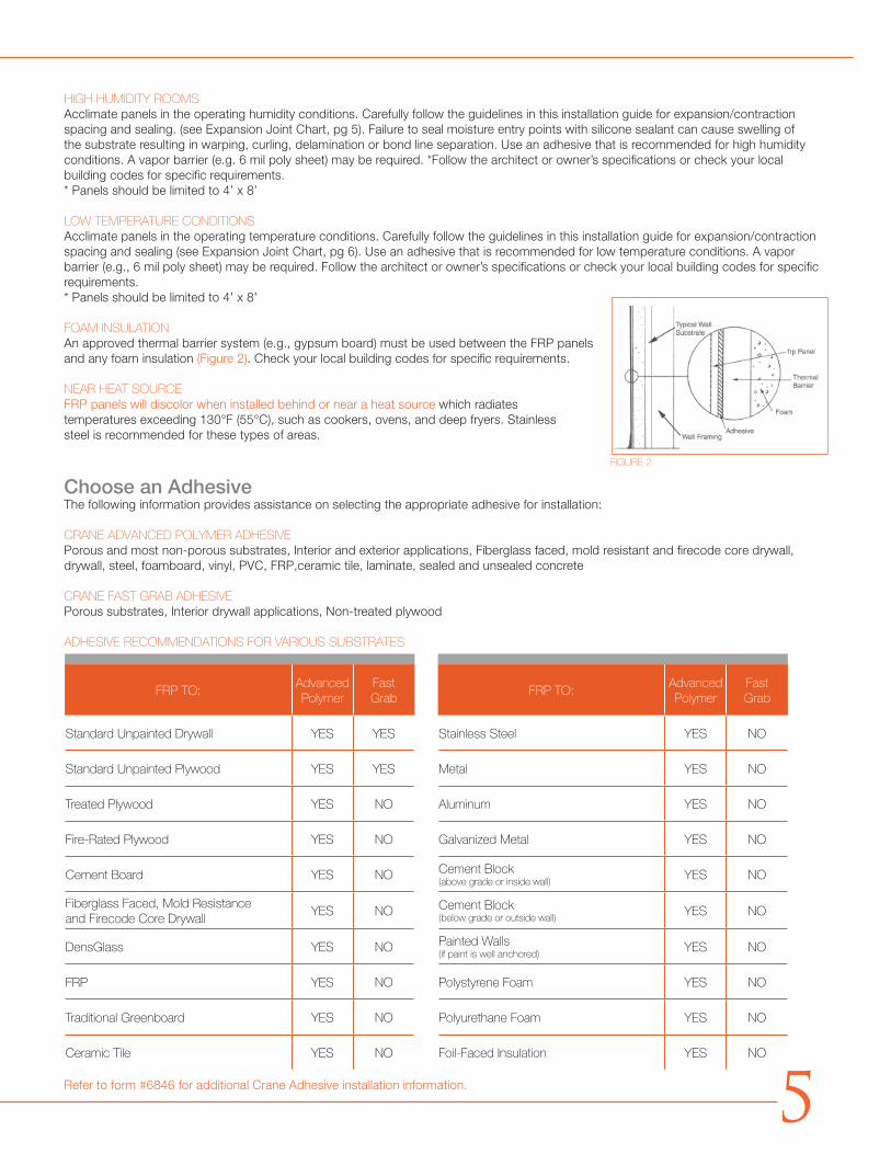
FOAM INSULATIONAn approved thermal barrier system (e.g., gypsum board) must be used between the FRP panels and any foam insulation (Figure 2). Check your local building codes for specific requirements.
NEAR HEAT SOURCE FRP panels will discolor when installed behind or near a heat source which radiates temperatures exceeding 130°F (55°C), such as cookers, ovens, and deep fryers. Stainless steel is recommended for these types of areas.
Choose an AdhesiveThe following information provides assistance on selecting the appropriate adhesive for installation:
CRANE ADVANCED POLYMER ADHESIVEPorous and most non-porous substrates, Interior and exterior applications, Fiberglass faced, mold resistant and firecode core drywall, drywall, steel, foamboard, vinyl, PVC, FRP,ceramic tile, laminate, sealed and unsealed concrete
CRANE FAST GRAB ADHESIVEPorous substrates, Interior drywall applications, Non-treated plywood
ADHESIVE RECOMMENDATIONS FOR VARIOUS SUBSTRATES
Refer to form #6846 for additional Crane Adhesive installation information.
FIGURE 2
FRP TO:Advanced Polymer
FastGrab
FRP TO:Advanced Polymer
FastGrab
Standard Unpainted Drywall YES YES Stainless Steel YES NO
Standard Unpainted Plywood YES YES Metal YES NO
Treated Plywood YES NO Aluminum YES NO
Fire-Rated Plywood YES NO Galvanized Metal YES NO
Cement Board YES NO Cement Block(above grade or inside wall)
YES NO
Fiberglass Faced, Mold Resistance and Firecode Core Drywall
YES NO Cement Block(below grade or outside wall)
YES NO
DensGlass YES NO Painted Walls(if paint is well anchored)
YES NO
FRP YES NO Polystyrene Foam YES NO
Traditional Greenboard YES NO Polyurethane Foam YES NO
Ceramic Tile YES NO Foil-Faced Insulation YES NO
5
PRE-INSTALLATION PLANNING• Pre-fit each panel before fastening and/or adhering in place.• All cutting and drilling should be done prior to the application of adhesive.• Preplan for cove or base molding. FRP panels should be installed so that the bas e molding will not restrict normal panel movement
during expansion and contraction. Cut panels 1/4” short of where the base molding will extend; poured acrylic floor with built-in base cove should be in place prior to installation.
• When using rivets, pre-drill holes in the panels using a drill bit that is 1/4” larger than the rivet. Plan ahead so that fasteners will not interfere with moldings or other wall fixtures.
• When using mechanical fasteners through FRP to attach wall angles or other fixtures, pre-drill holes using a drill bit that is 1/4” larger than the mechanical fastener. Without oversizing the holes, the FRP will likely have bulges and/or buckles when panel movement occurs during expansion and contraction.
BASIC FRP INSTALLATION STEPS1. Trim panel to fit. Oversize pilot holes if drop-in ceiling wall angle is attached to and through FRP
(please allow for proper expansion and contraction)2. Radius corners of any cut out fixture openings.3. Apply adhesive to 100% of the backside of panel using a cross-hatch pattern using a trowel recommended by the adhesive
manufacturer. 4. Place panel on wall, leaving appropriate room at panel joints and corners for expansion and contraction. 5. Using a laminate roller, remove air pockets by rolling down and out toward the panel edge without a molding.6. Fit appropriate moldings to panels edge leaving a minimum of 1/8” for expansion between panel and molding stem.7. Install next panel.The nature of FRP panels is to expand and contract. Without leaving required room for expansion and contraction, FRP panels can develop buckles and/or bulges because panel movement will occur.
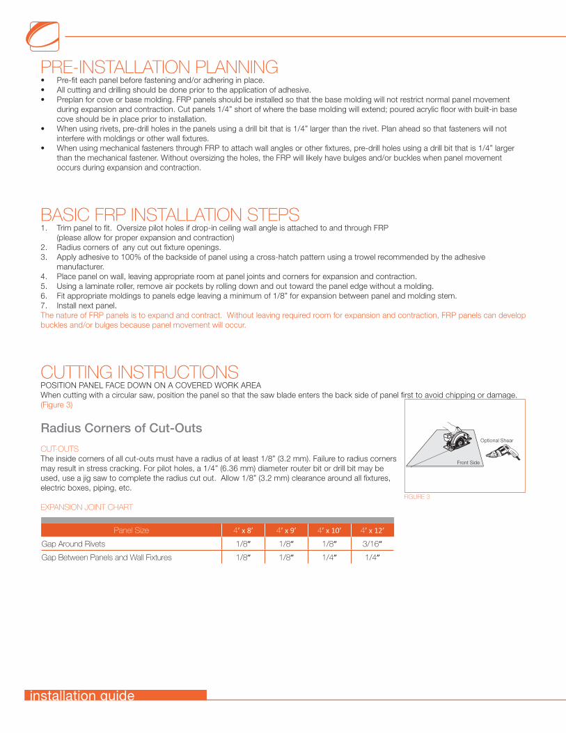
CUTTING INSTRUCTIONSPOSITION PANEL FACE DOWN ON A COVERED WORK AREAWhen cutting with a circular saw, position the panel so that the saw blade enters the back side of panel first to avoid chipping or damage. (Figure 3)
Radius Corners of Cut-Outs
CUT-OUTSThe inside corners of all cut-outs must have a radius of at least 1/8” (3.2 mm). Failure to radius corners may result in stress cracking. For pilot holes, a 1/4” (6.36 mm) diameter router bit or drill bit may be used, use a jig saw to complete the radius cut out. Allow 1/8” (3.2 mm) clearance around all fixtures, electric boxes, piping, etc.
EXPANSION JOINT CHART
Optional Shear
Front Side
FIGURE 3
Panel Size 4’ x 8’ 4’ x 9’ 4’ x 10’ 4’ x 12’
Gap Around Rivets 1/8” 1/8” 1/8” 3/16”
Gap Between Panels and Wall Fixtures 1/8” 1/8” 1/4” 1/4”
installation guide
ATTACHING TO WALL Generally, FRP panels can be installed using adhesive alone, fasteners alone, or a combination of adhesive and fasteners. The method used should be determined by the room and wall conditions (see the wall conditions noted on pages 4 & 5). Check your local building codes for any restrictions or guidelines regarding approved installation methods.
BEFORE STARTING, DETERMINE WHICH SEAM TREATMENT IS BEING USED. PLEASE REFER TO THE APPROPRIATE INSTRUCTIONS FOR THE TYPE OF SEAM TREATMENT BEING USED.Moldings | Color Coordinating Caulk | Seam Sealant
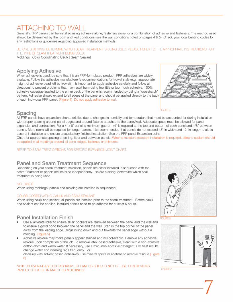
Applying AdhesiveWhen adhesive is used, be sure that it is an FRP-formulated product. FRP adhesives are widely available. Follow the adhesive manufacturer’s recommendations for trowel style (e.g., appropriate height of adhesive bead left by trowel). It is important to apply adhesive carefully and follow all directions to prevent problems that may result from using too little or too much adhesive. 100% adhesive coverage applied to the entire back of the panel is recommended by using a “crosshatch” pattern. Adhesive should extend to all edge s of the panel and should be applied directly to the back of each individual FRP panel. (Figure 4) Do not apply adhesive to wall.
SpacingAll FRP panels have expansion characteristics due to changes in humidity and temperature that must be accounted for during installation with proper spacing around panel edges and around fixtures attached to the panel/wall. Adequate space must be allowed for panel expansion and contraction. For a 4’ x 8’ panel, a minimum gap of 1/4” is required at the top and bottom of each panel and 1/8” between panels. More room will be required for longer panels. It is recommended that panels do not exceed 48” in width and 12’ in length to aid in ease of installation and ensure a satisfactory finished installation. See the FRP panel Expansion Joint Chart for appropriate spacing at ceiling, floor and between panels. When a moisture resistant installation is required, silicone sealant should be applied in all moldings around all panel edges, fastener, and fixtures.
REFER TO SEAM TREAT OPTIONS FOR SPECIFIC EXPANSION JOINT CHART.
Panel and Seam Treatment SequenceDepending on your seam treatment selection, panels are either installed in sequence with the seam treatment or panels are installed independently. Before starting, determine which seal treatment is being used.
MOLDINGSWhen using moldings, panels and molding are installed in sequenced.
COLOR COORDINATING CAULK AND SEAM SEALANTWhen using caulk and sealant, all panels are installed prior to the seam treatment. Before caulk and sealant can be applied, installed panels need to be adhered for at least 6 hours.
Panel Installation Finish• Use a laminate roller to ensure all air pockets are removed between the panel and the wall and
to ensure a good bond between the panel and the wall. Start in the top corner of the panel away from the leading edge. Begin rolling down and out towards the panel edge without a molding. (Figure 5)
• Adhesive residue may make panels appear stained and will collect dirt. Remove any adhesive residue upon completion of the job. To remove latex-based adhesive, clean with a non-abrasive cotton cloth and warm water. If necessary, use a mild, non-abrasive detergent. For best results, change water and cleaning rags frequently. For clean-up with solvent based adhesives, use mineral spirits or acetone to remove residue (Figure 6).
NOTE: SOLVENT-BASED OR ABRASIVE CLEANERS SHOULD NOT BE USED ON DESIGNS PANELS OR PATTERN MATCHED MOLDINGS
FIGURE 4
FIGURE 5
FIGURE 6
7
SEAM TREATMENT OPTIONSBefore starting, determine which seam treatment is being used.
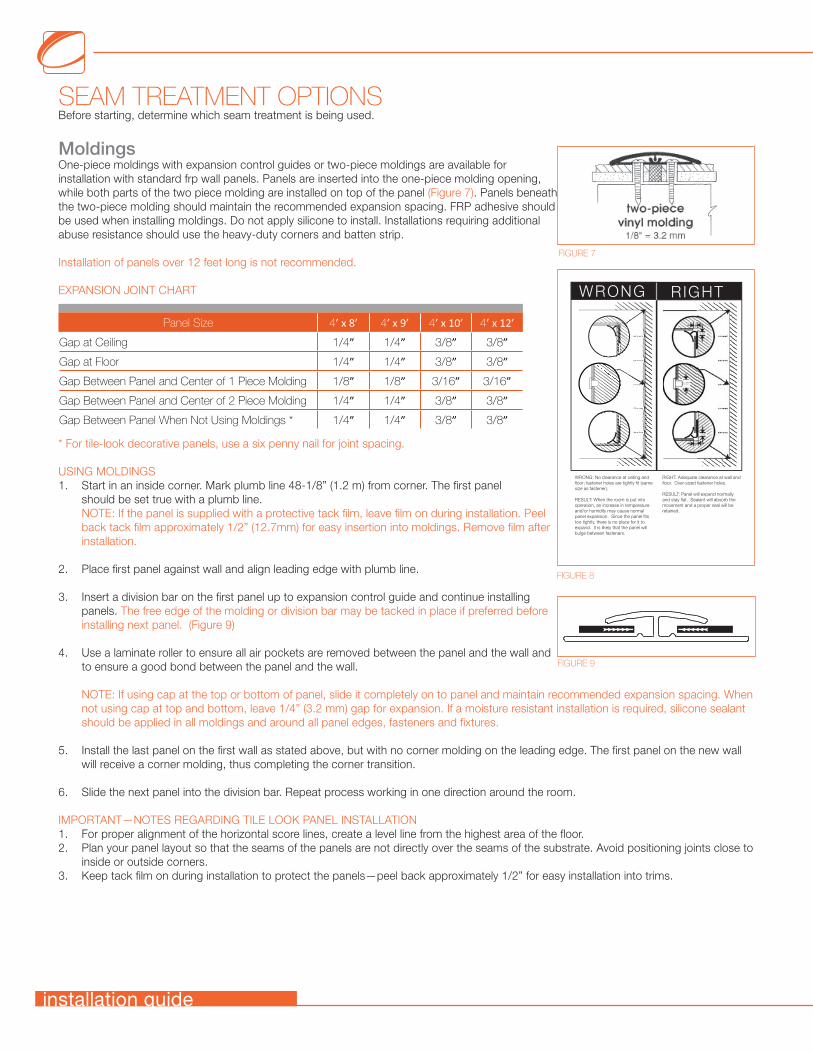
MoldingsOne-piece moldings with expansion control guides or two-piece moldings are available for installation with standard frp wall panels. Panels are inserted into the one-piece molding opening, while both parts of the two piece molding are installed on top of the panel (Figure 7). Panels beneath the two-piece molding should maintain the recommended expansion spacing. FRP adhesive should be used when installing moldings. Do not apply silicone to install. Installations requiring additional abuse resistance should use the heavy-duty corners and batten strip.
Installation of panels over 12 feet long is not recommended.
EXPANSION JOINT CHART
* For tile-look decorative panels, use a six penny nail for joint spacing.
USING MOLDINGS1. Start in an inside corner. Mark plumb line 48-1/8” (1.2 m) from corner. The first panel
should be set true with a plumb line.NOTE: If the panel is supplied with a protective tack film, leave film on during installation. Peel back tack film approximately 1/2” (12.7mm) for easy insertion into moldings. Remove film after installation.
2. Place first panel against wall and align leading edge with plumb line.
3. Insert a division bar on the first panel up to expansion control guide and continue installing panels. The free edge of the molding or division bar may be tacked in place if preferred before installing next panel. (Figure 9)
4. Use a laminate roller to ensure all air pockets are removed between the panel and the wall and to ensure a good bond between the panel and the wall.
NOTE: If using cap at the top or bottom of panel, slide it completely on to panel and maintain recommended expansion spacing. When not using cap at top and bottom, leave 1/4” (3.2 mm) gap for expansion. If a moisture resistant installation is required, silicone sealant should be applied in all moldings and around all panel edges, fasteners and fixtures.
5. Install the last panel on the first wall as stated above, but with no corner molding on the leading edge. The first panel on the new wall will receive a corner molding, thus completing the corner transition.
6. Slide the next panel into the division bar. Repeat process working in one direction around the room.
IMPORTANT—NOTES REGARDING TILE LOOK PANEL INSTALLATION1. For proper alignment of the horizontal score lines, create a level line from the highest area of the floor.2. Plan your panel layout so that the seams of the panels are not directly over the seams of the substrate. Avoid positioning joints close to
inside or outside corners.3. Keep tack film on during installation to protect the panels—peel back approximately 1/2” for easy installation into trims.
3/8”
14“
1/4”
1/4”
14“
WRONG RIGHT
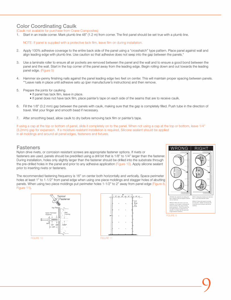
WRONG: No clearance at ceiling and floor; fastener holes are tightly fit (same size as fastener).
RESULT: When the room is put into operation, an increase in temperature and/or humidity may cause normal panel expansion. Since the panel fits too tightly, there is no place for it to expand. It is likely that the panel will bulge between fasteners.
RIGHT: Adequate clearance at wall and floor. Over-sized fastener holes.
RESULT: Panel will expand normally and stay flat. Sealant will absorb the movement and a proper seal will be retained.
1/2”
FIGURE 8
FIGURE 7
FIGURE 9
Panel Size 4’ x 8’ 4’ x 9’ 4’ x 10’ 4’ x 12’
Gap at Ceiling 1/4” 1/4” 3/8” 3/8”
Gap at Floor 1/4” 1/4” 3/8” 3/8”
Gap Between Panel and Center of 1 Piece Molding 1/8” 1/8” 3/16” 3/16”
Gap Between Panel and Center of 2 Piece Molding 1/4” 1/4” 3/8” 3/8”
Gap Between Panel When Not Using Moldings * 1/4” 1/4” 3/8” 3/8”
installation guide
Color Coordinating Caulk(Caulk not available for purchase from Crane Composites)1. Start in an inside corner. Mark plumb line 48” (1.2 m) from corner. The first panel should be set true with a plumb line.
NOTE: If panel is supplied with a protective tack film, leave film on during installation.
2. Apply 100% adhesive coverage to the entire back side of the panel using a “crosshatch” type pattern. Place panel against wall and align leading edge with plumb line. Use caution so that adhesive does not seep into the gap between the panels.*
3. Use a laminate roller to ensure all air pockets are removed between the panel and the wall and to ensure a good bond between the panel and the wall. Start in the top corner of the panel away from the leading edge. Begin rolling down and out towards the leading panel edge. (Figure 5)
4. Hammer six-penny finishing nails against the panel leading edge two feet on center. This will maintain proper spacing between panels. **Leave nails in place until adhesive sets up (per manufacturer’s instructions) and then remove.
5. Prepare the joints for caulking. • If panel has tack film, leave in place. • If panel does not have tack film, place painter’s tape on each side of the seams that are to receive caulk.
6. Fill the 1/8” (3.2 mm) gap between the panels with caulk, making sure that the gap is completely filled. Push tube in the direction of travel. Wet your finger and smooth bead if necessary.
7. After smoothing bead, allow caulk to dry before removing tack film or painter’s tape.
If using a cap at the top or bottom of panel, slide it completely on to the panel. When not using a cap at the top or bottom, leave 1/4” (3.2mm) gap for expansion. If a moisture resistant installation is required, Silicone sealant should be applied in all moldings and around all panel edges, fasteners and fixtures.
FastenersNylon drive rivets, or corrosion resistant screws are appropriate fastener options. If rivets or fasteners are used, panels should be predrilled using a drill bit that is 1/8” to 1/4” larger than the fastener. During installation, holes only slightly larger than the fastener should be drilled into the substrate through the pre-drilled holes in the panel and prior to any adhesive application (Figure 10). Apply silicone sealant prior to inserting rivets or fasteners.
The recommended fastening frequency is 16” on center both horizontally and vertically. Space perimeter holes at least 1” to 1-1/2” from panel edge when using one piece moldings and stagger holes of abutting panels. When using two piece moldings put perimeter holes 1-1/2” to 2” away from panel edge (Figure 8, Figure 11).
3/8”
14“
1/4”
1/4”
14“
WRONG RIGHT
WRONG: No clearance at ceiling and floor; fastener holes are tightly fit (same size as fastener).
RESULT: When the room is put into operation, an increase in temperature and/or humidity may cause normal panel expansion. Since the panel fits too tightly, there is no place for it to expand. It is likely that the panel will bulge between fasteners.
RIGHT: Adequate clearance at wall and floor. Over-sized fastener holes.
RESULT: Panel will expand normally and stay flat. Sealant will absorb the movement and a proper seal will be retained.
1/2”
FIGURE 8
FIGURE 10 FIGURE 11
9
Seam Sealant
WALL PREPARATION1. Surfaces should be free of grease, dirt, and other contaminants. Clean seams as necessary with a
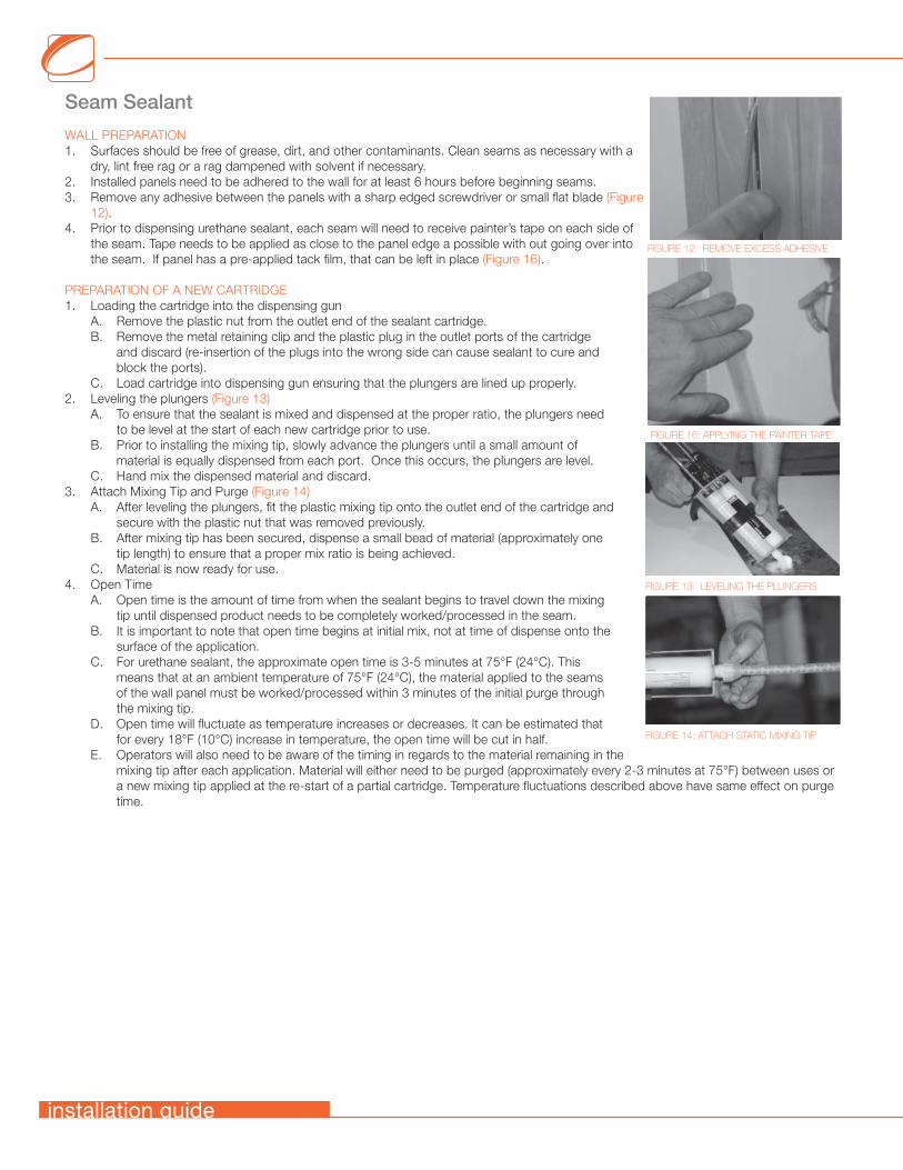
dry, lint free rag or a rag dampened with solvent if necessary.2. Installed panels need to be adhered to the wall for at least 6 hours before beginning seams.3. Remove any adhesive between the panels with a sharp edged screwdriver or small flat blade (Figure
12).4. Prior to dispensing urethane sealant, each seam will need to receive painter’s tape on each side of
the seam. Tape needs to be applied as close to the panel edge a possible with out going over into the seam. If panel has a pre-applied tack film, that can be left in place (Figure 16).
PREPARATION OF A NEW CARTRIDGE1. Loading the cartridge into the dispensing gun
A. Remove the plastic nut from the outlet end of the sealant cartridge.B. Remove the metal retaining clip and the plastic plug in the outlet ports of the cartridge
and discard (re-insertion of the plugs into the wrong side can cause sealant to cure and block the ports).
C. Load cartridge into dispensing gun ensuring that the plungers are lined up properly.2. Leveling the plungers (Figure 13)
A. To ensure that the sealant is mixed and dispensed at the proper ratio, the plungers need to be level at the start of each new cartridge prior to use.
B. Prior to installing the mixing tip, slowly advance the plungers until a small amount of material is equally dispensed from each port. Once this occurs, the plungers are level.
C. Hand mix the dispensed material and discard.3. Attach Mixing Tip and Purge (Figure 14)
A. After leveling the plungers, fit the plastic mixing tip onto the outlet end of the cartridge and secure with the plastic nut that was removed previously.
B. After mixing tip has been secured, dispense a small bead of material (approximately one tip length) to ensure that a proper mix ratio is being achieved.
C. Material is now ready for use.4. Open Time
A. Open time is the amount of time from when the sealant begins to travel down the mixing tip until dispensed product needs to be completely worked/processed in the seam.
B. It is important to note that open time begins at initial mix, not at time of dispense onto the surface of the application.
C. For urethane sealant, the approximate open time is 3-5 minutes at 75°F (24°C). This means that at an ambient temperature of 75°F (24°C), the material applied to the seams of the wall panel must be worked/processed within 3 minutes of the initial purge through the mixing tip.
D. Open time will fluctuate as temperature increases or decreases. It can be estimated that for every 18°F (10°C) increase in temperature, the open time will be cut in half.
E. Operators will also need to be aware of the timing in regards to the material remaining in the mixing tip after each application. Material will either need to be purged (approximately every 2-3 minutes at 75°F) between uses or a new mixing tip applied at the re-start of a partial cartridge. Temperature fluctuations described above have same effect on purge time.
FIGURE 13: LEVELING THE PLUNGERS
FIGURE 14: ATTACH STATIC MIXING TIP
FIGURE 16: APPLYING THE PAINTER TAPE
FIGURE 12: REMOVE EXCESS ADHESIVE
installation guide
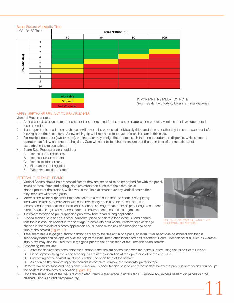
Seam Sealant Workability Time1/8” - 3/16” Bead
IMPORTANT INSTALLATION NOTE Seam Sealant workability begins at initial dispense
APPLY URETHANE SEALANT TO SEAMS/JOINTSGeneral Process notes:1. At end user discretion as to the number of operators used for the seam seal application process. A minimum of two operators is
recommended.2. If one operator is used, then each seam will have to be processed individually (filled and then smoothed by the same operator before
moving on to the next seam). A new mixing tip will likely need to be used for each seam in this case.3. For multiple operators (two or more), the end user may design the process such that one operator can dispense, while a second
operator can follow and smooth the joints. Care will need to be taken to ensure that the open time of the material is not exceeded in these scenarios.
4. Seam Seal Process order should be:A. Vertical flat panel seamsB. Vertical outside cornersC. Vertical inside cornersD. Floor and/or ceiling jointsE. Windows and door frames
VERTICAL FLAT PANEL SEAMS1. Vertical Seams should be processed first as they are intended to be smoothed flat with the panel.
Inside corners, floor, and ceiling joints are smoothed such that the seam sealer stands proud of the surface, which would require placement over any vertical seams that may interface with these joints.
2. Material should be dispensed into each seam at a rate such that the seam is completely filled with sealant but completed within the necessary open time for the sealant. It is recommended that sealant is installed in sections no longer than 3’ for all panel length as a bench mark. Section length will vary dependent on environmental conditions at job site.
3. It is recommended to pull dispensing gun away from bead during application.4. A good technique is to add a small horizontal piece of painters tape every 3’ and ensure
that there is enough sealant in the cartridge to complete a full seam. Performing a cartridge change in the middle of a seam application could increase the risk of exceeding the open time of the sealant (Figure 17).
5. If the seam has a large gap and/or cannot be filled by the sealant in one pass, an initial “filler bead” can be applied and then a secondary bead can be applied over the top of the initial bead after initial bead has reached full cure. Mechanical filler, such as weather-strip putty, may also be used to fill large gaps prior to the application of the urethane seam sealant.
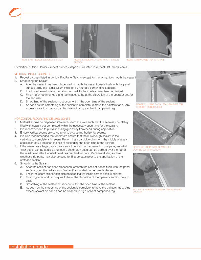
6. Smoothing the sealantA. After the sealant has been dispensed, smooth the sealant beads flush with the panel surface using the Inline Seam Finisher.B. Finishing/smoothing tools and techniques are at the discretion of the operator and/or the end user.C. Smoothing of the sealant must occur within the open time of the sealant.D. As soon as the smoothing of the sealant is complete, remove the horizontal painters tape.
7. Remove horizontal tape and begin next 3’ section. A good technique is to apply the sealant below the previous section and “bump up” the sealant into the previous section (Figure 19).
8. Once the all sections of the wall are completed, remove the vertical painters tape. Remove Any excess sealant on panels can be cleaned using a solvent dampened rag
Temperature (°F)
70 80 90 100
Tim
e (M
inut
es)
123456789
10
WorkableSuspect
Not Workable
FIGURE 17: APPLYING THE PAINTER TAPE HORIZONTAL IN 3’ SECTIONS
11
For Vertical outside Corners, repeat process steps 1-8 as listed in Vertical Flat Panel Seams
VERTICAL INSIDE CORNERS1. Repeat process listed in Vertical Flat Panel Seams except for the format to smooth the sealant2. Smoothing the Sealant
A. After the sealant has been dispensed, smooth the sealant beads flush with the panel surface using the Radial Seam Finisher if a rounded corner joint is desired.
B. The Inline Seam Finisher can also be used if a flat inside corner bead is desired.C. Finishing/smoothing tools and techniques to be at the discretion of the operator and/or
the end user.D. Smoothing of the sealant must occur within the open time of the sealant. E. As soon as the smoothing of the sealant is complete, remove the painters tape. Any
excess sealant on panels can be cleaned using a solvent dampened rag.
HORIZONTAL FLOOR AND CEILING JOINTS1. Material should be dispensed into each seam at a rate such that the seam is completely
filled with sealant but completed within the necessary open time for the sealant.2. It is recommended to pull dispensing gun away from bead during application.3. Ensure vertical seams are cured prior to processing horizontal seams.4. It is also recommended that operators ensure that there is enough sealant in the
cartridge to complete a full seam. Performing a cartridge change in the middle of a seam application could increase the risk of exceeding the open time of the sealant.
5. If the seam has a large gap and/or cannot be filled by the sealant in one pass, an initial “filler bead” can be applied and then a secondary bead can be applied over the top of the initial bead after the initial bead has reached full cure. Mechanical filler, such as weather-strip putty, may also be used to fill large gaps prior to the application of the urethane sealant.
6. Smoothing the Sealant:A. After the sealant has been dispensed, smooth the sealant beads flush with the panel
surface using the radial seam finisher if a rounded corner joint is desired.B. The inline seam finisher can also be used if a flat inside corner bead is desired.C. Finishing tools and techniques to be at the discretion of the operator and/or the end
user.D. Smoothing of the sealant must occur within the open time of the sealant.E. As soon as the smoothing of the sealant is complete, remove the painters tape. Any
excess sealant on panels can be cleaned using a solvent dampened rag.
FIGURE 21: USING RADIAL SEAM FINISHER FOR ROUNDER CORNER JOINT
FIGURE 22: HORIZONTAL SEAM FILLED COMPLETELY WITH SEALANT
FIGURE 23: HORIZONTAL FINISH WITH ROUNDED CORNER
FIGURE 18: REMOVING EXCESS SEALANT FIGURE 20: REMOVING PAINTER’S TAPEFIGURE 19: BUMP ADHESIVE IN TO PREVIOUS SECTION
installation guide
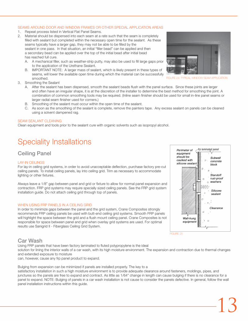
SEAMS AROUND DOOR AND WINDOW FRAMES OR OTHER SPECIAL APPLICATION AREAS1. Repeat process listed in Vertical Flat Panel Seams.2. Material should be dispensed into each seam at a rate such that the seam is completely
filled with sealant but completed within the necessary open time for the sealant. As these seams typically have a larger gap, they may not be able to be filled by the sealant in one pass. In that situation, an initial “filler bead” can be applied and then a secondary bead can be applied over the top of the initial bead after initial bead has reached full cure.A. A mechanical filler, such as weather-strip putty, may also be used to fill large gaps prior
to the application of the Urethane Sealant.B. IMPORTANT NOTE: A larger mass of sealant, which is likely present in these types of
seams, will lower the available open time during which the material can be successfully smoothed.
3. Smoothing the SealantA. After the sealant has been dispensed, smooth the sealant beads flush with the panel surface. Since these joints are larger
and often have an irregular shape, it is at the discretion of the installer to determine the best method for smoothing the joint. A combination of common smoothing tools may be required. (Inline seam finisher should be used for small in-line panel seams or larger radial seam finisher used for corners.)
B. Smoothing of the sealant must occur within the open time of the sealant. C. As soon as the smoothing of the sealant is complete, remove the painters tape. Any excess sealant on panels can be cleaned
using a solvent dampened rag.
SEAM SEALANT CLEANINGClean equipment and tools prior to the sealant cure with organic solvents such as isopropyl alcohol.
Speciality InstallationsCeiling Panel
LAY-IN CEILINGSFor lay-in ceiling grid systems, in order to avoid unacceptable deflection, purchase factory pre-cut ceiling panels. To install ceiling panels, lay into ceiling grid. Trim as necessary to accommodate lighting or other fixtures.
Always leave a 1/8” gap between panel and grid or fixture to allow for normal panel expansion and contraction. FRP grid systems may require specially sized ceiling panels. See the FRP grid system installation guide. Do not attach ceiling grid through top of panels.
WHEN USING FRP PANELS IN A CEILING GRIDIn order to minimize gaps between the panel and the grid system, Crane Composites strongly recommends FRP ceiling panels be used with butt-end ceiling grid systems. Smooth FRP panels will highlight the space between the grid and a flush mount ceiling panel. Crane Composites is not responsible for space between panel and grid when overlay grid systems are used. For optimal results use Sanigrid II - Fiberglass Ceiling Grid System.
Car WashUsing FRP panels that have been factory laminated to fluted polypropylene is the ideal solution for lining the interior walls of a car wash, with its high moisture environment. The expansion and contraction due to thermal changes and extended exposure to moisture can, however, cause any frp panel product to expand.
Bulging from expansion can be minimized if panels are installed properly. The key to a satisfactory installation in such a high moisture environment is to provide adequate clearance around fasteners, moldings, pipes, and junctures so the panels are free to expand and contract. As little as 1/64” change in length can cause bulging if there is no clearance for a panel to expand. NOTE: Bulging of panels in a car wash installation is not cause to consider the panels defective. In general, follow the wall panel installation instructions within this guide.
FIGURE 24: TYPICAL WINDOW SEAM APPLICATION
FIGURE 25
13
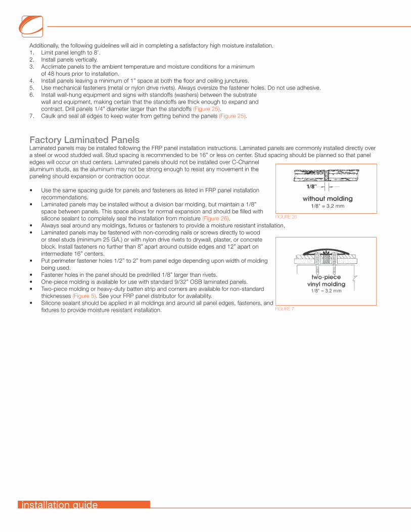
Additionally, the following guidelines will aid in completing a satisfactory high moisture installation.1. Limit panel length to 8’.2. Install panels vertically.3. Acclimate panels to the ambient temperature and moisture conditions for a minimum
of 48 hours prior to installation.4. Install panels leaving a minimum of 1” space at both the floor and ceiling junctures.5. Use mechanical fasteners (metal or nylon drive rivets). Always oversize the fastener holes. Do not use adhesive.6. Install wall-hung equipment and signs with standoffs (washers) between the substrate
wall and equipment, making certain that the standoffs are thick enough to expand and contract. Drill panels 1/4” diameter larger than the standoffs (Figure 25).
7. Caulk and seal all edges to keep water from getting behind the panels (Figure 25).
Factory Laminated PanelsLaminated panels may be installed following the FRP panel installation instructions. Laminated panels are commonly installed directly over a steel or wood studded wall. Stud spacing is recommended to be 16” or less on center. Stud spacing should be planned so that panel edges will occur on stud centers. Laminated panels should not be installed over C-Channel aluminum studs, as the aluminum may not be strong enough to resist any movement in the paneling should expansion or contraction occur.
• Use the same spacing guide for panels and fasteners as listed in FRP panel installation recommendations.
• Laminated panels may be installed without a division bar molding, but maintain a 1/8” space between panels. This space allows for normal expansion and should be filled with silicone sealant to completely seal the installation from moisture (Figure 26).
• Always seal around any moldings, fixtures or fasteners to provide a moisture resistant installation.• Laminated panels may be fastened with non-corroding nails or screws directly to wood
or steel studs (minimum 25 GA.) or with nylon drive rivets to drywall, plaster, or concrete block. Install fasteners no further than 8” apart around outside edges and 12” apart on intermediate 16” centers.
• Put perimeter fastener holes 1/2” to 2” from panel edge depending upon width of molding being used.
• Fastener holes in the panel should be predrilled 1/8” larger than rivets.• One-piece molding is available for use with standard 9/32” OSB laminated panels.• Two-piece molding or heavy-duty batten strip and corners are available for non-standard
thicknesses (Figure 5). See your FRP panel distributor for availability.• Silicone sealant should be applied in all moldings and around all panel edges, fasteners, and
fixtures to provide moisture resistant installation.
FIGURE 26
FIGURE 7
installation guide

AN IMPORTANT NOTE ABOUT MOISTURE RESISTANT SUBSTRATESMOISTURE-RESISTANT GYPSUM VARIES TREMENDOUSLY, WHILE SOME OF THESE NEW SURFACES ALLOW MOISTURE TO PENETRATE, OTHERS RETARD OR TOTALLY PREVENT PENETRATION OF WATER OR SOLVENT. TESTING BY CRANE COMPOSITES INDICATED THAT WHEN WATER BASED OR SOLVENT BASED FRP ADHESIVES ARE USED IN CONJUNCTION WITH MOISTURE RESISTANT GYPSUM THE ADHESIVE ABILITY TO CURE IS SEVERELY COMPROMISED IN THE CRUCIAL FIRST 24 HOURS OF INSTALLATION AND THE POTENTIAL FOR A SUCCESSFUL INSTALLATION IS GREATLY DIMINISHED. THE CONSTRUCTION TRADE IS BECOMING EXPOSED TO AN INCREASINGLY LARGE NUMBER OF NEW TYPES OF MOISTURE RESISTANT GYPSUM FROM THE DRYWALL INDUSTRY. GIVEN THESE TWO FACTS, IT IS RECOMMENDED THAT YOU CONTACT YOUR ADHESIVE MANUFACTURER’S TECHNICAL SUPPORT DEPARTMENT, PRIOR TO ANY FRP INSTALLATION OVER WALL SUBSTRATES OTHER THAN STANDARD GYPSUM. STANDARD GYPSUM IS CRANE COMPOSITES PREFERRED SUBSTRATE CHOICE WHEN INSTALLING FRP WALL PANELS. FRP OFFERS RESISTANCE TO MOLD, MILDEW, AND BACTERIA GROWTH AND HAS A HIGH IMPACT STRENGTH, HIGH MOISTURE RESISTANCE, CHEMICAL RESISTANCE AND STAIN RESISTANCE. A MOISTURE RESISTANT SUBSTRATE MAY NOT BE NECESSARY WHEN AN FRP FINISH IS SPECIFIED. HOWEVER, SHOULD A MOISTURE-RESISTANT GYPSUM BE REQUIRED PLEASE CONTACT ADHESIVE SUPPLIER TO REVIEW THE PROPOSED SUBSTRATE AND OBTAIN A RECOMMENDATION ON APPROPRIATE ADHESIVE FOR THAT TYPE OF SUBSTRATE SURFACE PRIOR TO INSTALLATION. CRANE COMPOSITES WILL NOT BE RESPONSIBLE FOR FAILED INSTALLATIONS DUE TO LACK OF ADHESIVE BOND STRENGTH BETWEEN THE ADHESIVE AND THE SUBSTRATE.
FOR QUESTIONS OR CONCERNS, PLEASE CONTACT:Crane Composites Customer Service Department
1.800.435.0080 | 1.815.467.8600
KEMPLY® LAMINATED PANELSKemply panels have not been tested for physical properties or fire resistance. All Glasbord finishes have been tested for surface burning characteristics (see Technical Bulletins 6226, 6229, 6296, 7901 and 65020). Physical properties and fire resistance data on the substrate are available from the specific substrate manufacturer. Crane Composites makes no representation or warranty as to the composite panel fitness for any specific application, overall physical properties, fire resistance, or burning characteristics. The intended use of laminated panels that use fluted polypropylene as a substrate, is to line the walls or ceilings of car washes and agricultural buildings. Installation of these panels in any application should be approved by the local building code official before panels are ordered. Crane Composites cannot ensure code compliance in all situations.
FLAME SPREAD AND SMOKE DEVELOPMENT RATINGSThe numerical flame spread and smoke development ratings are not intended to reflect alleged hazards presented by Crane Composites products under actual fire conditions and this product has not been tested by Crane Composites except as set forth below. These ratings are determined by small-scale tests conducted by Underwriters Laboratories and other independent testing facilities using the American Society for Testing and Materials E-84 test standard (commonly referred to as the “Tunnel Test”).CRANE COMPOSITES PROVIDES THESE RATINGS FOR MATERIAL COMPARISON PURPOSES ONLY. Like other organic building materials (e.g. wood), panels made of fiberglass reinforced plastic resins will burn. When ignited, FRP may produce dense smoke very rapidly. All smoke is toxic. Fire safety requires proper design of facilities and fire suppression systems, as well as precautions during construction and occupancy. Local codes, insurance requirements and any special needs of the product user will determine the correct fire-rated interior finish and fire suppression system necessary for a specific installation. We believe all information given is accurate, without a guarantee. Since conditions of use are beyond our control, all risks are assumed by the user. Nothing herein shall be construed as a recommendation for uses which infringe on valid patents or as extending a license under valid patents. www.astm.org/Standards/E84.htm.
15

cranecomposites.com | 1.800.435.0080 | 1.815.467.8666 [fax] | [email protected]
A global leading provider of resilient wall and ceiling coverings. Kemlite® was established in 1954 and the company changed names to Crane Composites in 2007. Crane Composites is headquartered in Channahon, IL and all our products are manufactured in the United States. We work with hundreds of distributors, ensuring our products are easily accessible and readily available to our customers.
The following are trademarks of Crane Composites, Inc. or a related company: Glasbord, Kemlite, Kemply, Surfaseal, Sanigrid, Silhouette Trims and Varietex
6876 | REV. 10 | 6.15 (7543)