Embed Size (px)
Citation preview
381333–005 B50 Hanover Road, Florham Park, New Jersey 07932–1591 USAFor sales or service call 1 800 800–2726 (ASCO) www.ascopower.com
ASCO POWER TECHNOLOGIES CANADA PO Box 1238, 17 Airport Road, Brantford, Ontario, Canada N3T 5T3
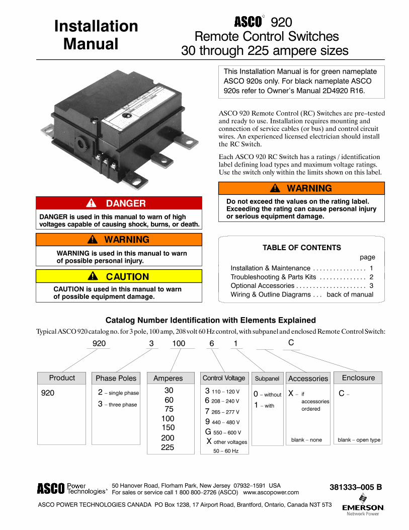
InstallationManual
920Remote Control Switches
30 through 225 ampere sizes
DANGER is used in this manual to warn of highvoltages capable of causing shock, burns, or death.
WARNING is used in this manual to warnof possible personal injury.
CAUTION is used in this manual to warnof possible equipment damage.
!This Installation Manual is for green nameplateASCO 920s only. For black nameplate ASCO920s refer to Owner’s Manual 2D4920 R16.
ASCO 920 Remote Control (RC) Switches are pre–testedand ready to use. Installation requires mounting andconnection of service cables (or bus) and control circuitwires. An experienced licensed electrician should installthe RC Switch.
Each ASCO 920 RC Switch has a ratings / identificationlabel defining load types and maximum voltage ratings.Use the switch only within the limits shown on this label.
Do not exceed the values on the rating label.Exceeding the rating can cause personal injuryor serious equipment damage.
TABLE OF CONTENTSpage
Installation & Maintenance 1. . . . . . . . . . . . . . . .Troubleshooting & Parts Kits 2. . . . . . . . . . . . . .Optional Accessories 3. . . . . . . . . . . . . . . . . . . . .Wiring & Outline Diagrams back of manual. . .
Catalog Number Identification with Elements ExplainedTypicalASCO920catalogno. for 3pole, 100amp, 208 volt 60Hz control, with subpanel and enclosedRemoteControlSwitch:
920 3 100 6 1
Phase PolesProduct Amperes Control Voltage Accessories
X –
3 – three phase
2 – single phase
9 440 – 480 V
7 265 – 277 V
G 550 – 600 V
X other voltages
920
Enclosure
C –
blank – open type
C
Subpanel
0 – without30
100150200225
7560 6 208 – 240 V
3 110 – 120 V
50 – 60 Hz
1 – with
ifaccessoriesordered
blank – none

INSTALLATION
1
To prevent malfunction or shortened life, protectthe switch from construction grit and metal chips.
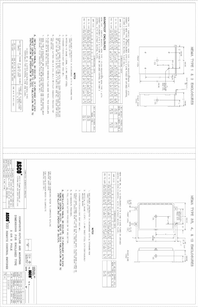
Mounting: Two Outline and Mounting Diagrams arefurnished; one for enclosed switches, the other for open–type switches. Select the appropriate diagram and mountthe RC Switch (in any position). All mounting detailsand instructions are shown on the diagram.
RC Switches on subpanels must be mounted withsupplied insulator bushings and insulator pieces.Be sure the insulator pieces are behind the switchand use the insulator bushingsunder thehardware.
Figure 1. Required insulator bushings and backinginsulators for RC Switches mounted on subpanels.
Service Connections: For panelboard mounting, theextended bus plates provide both the mechanical supportand the electrical connection. Switches on subpanels arefurnished with solderless lugs for copper or aluminum wire.Outline and Mounting Diagram lists wire sizes accepted.
Remove surface oxides from wires by cleaning with a wirebrush. When aluminum conductor is used, apply jointcompound to conductor. Tighten conductor and carefullywipe away excess compound. Maintain proper electricalclearance between live metal parts and grounded metal.
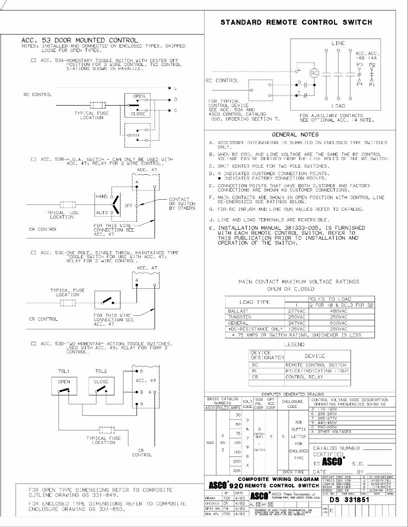
Control Line Connections: Control circuit connectionsdesignated L, O, C are supplied with clamp typeterminals. These terminals accept wire sizes #14–10AWG Cu. Simply insert appropriate control wires andtighten terminal clamp screws. See the Wiring Diagram.
Tighten all electrical connections; refer to thetorque specified on the label on the RC Switch.
Table A lists the maximum distances and minimum wiresizes that can be run between a control station and oneASCO 920 switch.
Table A – Line Run
Min.Wire Size
Maximum Distance (feet) 1for these AC Control VoltagesWire Size
AWG 120 V 208 V 240 V 277 V141210
75012002000
165026004200
276043006900
3950635010000
1 For ambient temperatures to 40˚C.
Do not exceed these distancesfor proper switch operation.
Line run can be extended by use of Auxiliary ControlRelays. See page 3.
Table B provides the ASCO 920 coil inrush current andminimum control circuit fuse sizes.
Table B – Inrush Current / Minimum Fuse
AmpsInrush Current / Fuse (amps) 2for these AC Control VoltagesAmps
120 V 208 V 240 V 277 V 480 VInrush 11.3 5.15 6.4 7 7Fuse 3 1.5 1.5 1.5 3
2 Fuse value listed will also protect ASCO920against abnormal operating conditions.
MAINTENANCE
Annual preventive maintenance will insure highreliability and long life for the ASCO 920 RC Switch.
Keep the Switch clean. De–energize all sources, thenbrush and vacuum away any excessive dust accumulation.
Maintain Switch Lubrication. Under normal service,relubrication is not required. Renew factory lubricationif switch is subjected to severe dust or abnormaloperating conditions, and if the coil is replaced. Only useLubrication Kit 625549; do not use oil or any other typeof lubricant.
Inspect Main Current–Carrying Contacts.De–energize all sources, then remove cover to checkcontact condition. Discoloration or slight pitting doesnot affect contact efficiency. Replace the contacts whenthey become pitted, excessively worn, or appear to beoverheated.
The arc chutes are held in place by the cover.If the arc chutes are removed, be sure they areput back in place with “top” visable. Make surethe cover is fully seated before tightening thecover screws. (Do not over–tighten).
2
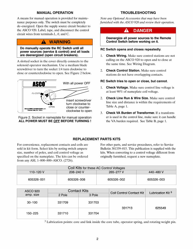
MANUAL OPERATION
A means for manual operation is provided for mainte-nance purposes only. The switch must be completelyde–energized. Open the supply source circuit breaker tothe ASCO 920. Label, tape, and disconnect the controlcircuit wires from terminals L, 0, and C.
Do manually operate the RC Switch until allpower sources (service & control) and all loadsare deenergized (open circuit breakers).
A slotted socket in the cover directly connects to thesolenoid operator mechanism. Use a medium bladescrewdriver to turn the socket 1/4 turn clockwise toclose or counterclockwise to open. See Figure 2 below.
insert screwdriverturn clockwise toclose or counter-clockwise to open
With all power OFF
Figure 2. Socket in nameplate for manual operationALL POWER MUST BE OFF BEFORE TURNING !
TROUBLESHOOTING
Note any Optional Accessories that may have beenfurnished with the ASCO 920 and review their operation.
Deenergize all power sources to the RemoteControl Switch before working on it.
RC Switch opens and closes repeatedly.
1. Check Wiring.Make sure control stations are notcalling on the ASCO 920 to open and to close atthe same time. See Wiring Diagram.
2. Check Control Station.Make sure controlstations do not have overlapping contacts.
RC Switch tries to open or close, but cannot.
1. Check Voltage.Make sure control line voltage isat least 90% of nameplate coil voltage.
2. Check Line Run & Wire Size.Make sure controlline size and distance is within the requirements ofTable A, page 1.
3. Check VA Burden of Transformer. If a transform-er is used in the control line, make sure it can handlethe VA burden required. See Table B, page 1.
REPLACEMENT PARTS KITS
For convenience, replacement contacts and coils aresold in kit form. Select kits by noting switch amperesize, number of poles, and coil control voltage asspecified on the nameplate. The kits can be orderedfrom any ASI, 1–800–800–ASCO. (2726).
For other parts, and service procedures, refer to ServiceBulletin 381339–015. This publication is supplied with thekits. When converting to a control voltage different fromoriginally furnished, request a new nameplate.
Coil Kits for these AC Control Voltages110–120 V 208–240 V 265–277 V 440–480 V
605326–001 605326–008 605326–002 605326–003
ASCO 920 Contact KitsCoil Control Contact Kit Lubrication Kit 3ASCO 920
amp. size 2 Pole 3 PoleCoil Control Contact Kit Lubrication Kit 3
30–100 331709 331703
331713 625549
150–225 331710 331704
331713 625549
3 Lubrication points: core and link inside the core tube, operator spring, and rotating weight pin.

OPTIONAL ACCESSORIES
3
Pilot Lights, Optional Accessory 9These pilot lights, if furnished, are connected andinstalled in the enclosure door, or are supplied loose foropen type switches. Each neon light requires a 1/2”diameter round hole and can be installed in panels up to0. 1” thick. See the Wiring Diagram. Acc. 9s can beadded later in Kit form. Kit voltage must be the same asRC Switch control voltage (coil).Acc. 9A light comes on when main contacts are closed.Acc. 9B light comes on when main contacts are open.A resistor is used for 208–277 VRC control. It is suppliedon a terminal block with connections labeled 1, 2.Acc. Description Kit
9A110–120 V 333270–006
9A 208–277 V 333270–007
9B110–120 V 333271–006
9B 208–277 V 333271–007
Auxiliary Contacts, Optional Accessory 14Acc. 14 auxiliary contacts are installed on the right side ofthe ASCO 920. Terminals accept wire size #14 AWG Cu.Acc. Description Kit14A14B
two auxiliary contacts (14A & 14B)with bracket, cam, and screws 607039
Auxiliary Relays, Optional Acc. 47, 48, 49Optional auxiliary relays (Acc. 47, 48, 49) are useful:– When the control station is located at a distance great-er than allowable ASCO 920 line run (Table A, page 1).– When controlling device doesn’t have adequate cur-rent–carrying capability to control RC (Table B, page 1).– When the controlling device is a single–pole single–throw contact, which requires a 2–wire control line.– When Form 3 (start–stop) control is required.The relays have a low VA burden: Acc. 47 has 3.0 VA forac, 2.5 watts for dc; Acc. 48 & 49 have 2.0 VA for ac, 1.2watts for dc. Acc. 47 & 48 terminals accept wire sizes#22–12 AWG Cu; Acc. 49 accepts #18–12 AWG Cu.The relays are mounted and wired to the RC on enclosedswitches, or supplied loose with open type switches.
Two–Wire Control, Optional Accessory 47Acc. 47 is an auxiliary relay panel for 2–wire control ofthe ASCO 920, The relay panel must be energized toclose the ASCO 920 contacts, and de–energized to openthe ASCO 920 contacts. Therefore, use a single–pole,maintained–type control station (Acc. 53B or 53C).Order Catalog 32lA40 and specify relay coil voltage.
Three–Wire Control, Optional Accessory 48Acc. 48 is an auxiliary relay panel for 3–wire control ofthe ASCO 920. It has two relays. One relay must beenergized to open the ASCO 920 contracts; the otherrelay must be energized to close the ASCO 920 contacts.Therefore, use a single–pole, double–throw, momentary–
type control station (Acc. 53A). Order Catalog 321A36and specify relay coil voltage. See the Wiring Diagram.
Form 3 Control, Optional Accessory 49
Acc. 49 is an auxiliary relay for Form 3 control of theASCO 920. This relay must be energized to close theASCO 920 contacts; the relay must be de–energized toopen the ASCO 920 contacts. Therefore, use onenormally open and one normally closed separate controlstations (Acc. 53D). Order a mounting socket kit andplug---in relay listed below (specify relay control voltage).Acc. Description Kit49 mounting socket kit 295855
Acc. ACControl Relay Acc. DC
Control Relay
49A 24 V 115206 49F 12 V 11527449B 120 V 115201 49G 24 V 11527749C 208 V 115210 49H 32 V 11527949D 240 V 115202 49I 48 V 11528349E 277 V 115213 49J 110 V 115271
Control Line Fuses, Optional Accessory 52
These control line fuses are mounted for enclosedswitches, or are supplied loose for open type switches.Fuse block has #10–32 terminal screws. The cartridgefuses are suitable for ac only as listed onWiring Diagram.Acc. Description Kit
52A one 15 amp, 300 Vac type SC fusefor 300 Vac max. grounded 333272
52B two 15 amp 300 Vac type SC fusesfor 300 Vac max. ungrounded 333273
52C two 15 amp 600 Vac type KTK fusesfor 301---600 Vac max. ungrounded 333274
Door–Mounted Controls, Optional Acc. 53
These manual controls are connected and mounted onthe enclosure door, or are supplied loose for open typeswitches. See the Composite Wiring Diagram.Acc. Description Kit
53Amomentary toggle switchwith center–off position
for 3–wire control333275
53B3–position selector switch (HOA)
used with Acc. 47for 2–wire control
333276
53Cmaintained toggle switch
used with Acc. 47for 2–wire control
333277
53D2 momentary toggle switches
(1 normally closed, 1 norm. open)used with Acc. 49 for form 3 control
333278