Embed Size (px)
Citation preview

1
Installation 30″ Induction CooktopInstructions PHP900, ZHU30
31-10667 (06-07 JR)
TOOLS YOU WILL NEED
BEFORE YOU BEGINRead these instructions completely and carefully.
• IMPORTANT — Save these instructionsfor local inspector’s use.
• IMPORTANT — Observe all governingcodes and ordinances.
• Note to Installer – Be sure to leave theseinstructions with the Consumer.
• Note to Consumer – Keep these instructions for future reference.
• Product failure due to improper installation is not covered under the Warranty.
WARNING — This appliance must beproperly grounded.
• ATTENTION INSTALLER — ALLCOOKTOPS MUST BE HARD WIRED (DIRECTWIRED) INTO AN APPROVED JUNCTION BOX. A “PLUG AND RECEPTACLE” IS NOT PERMITTEDON THESE PRODUCTS.
• Proper installation is the responsibility of the installer and product failure due toimproper installation is NOT covered underwarranty.
Saber Saw
Pencil
Safety Glasses
1/8″ Drill Bit & Electric orHand Drill
Ruler or Straightedge
Phillips HeadScrewdriver
“If you have questions, call 800.GE.CARES or visit our website at: ge.com”“In Canada, call 800.561.3344 or visit our website at: geappliances.ca”
1/4″ Nut Driver
MATERIALS YOU WILL NEED
Large Size Wire Nuts
Junction Box (Sized for conduitper local electrical
codes.)
3/4” Strain Relief
PARTS INCLUDED
Baffle(For all installations
except over an oven.) 2 Hold-Down Brackets6 Hex-Head Screws
2 Thumbscrews
Foam Tape
2
Installation Instructions
IMPORTANT SAFETY INSTRUCTIONS
FOR YOUR SAFETY• For Personal Safety, remove house fuse or open
circuit breaker before beginning installation.Failure to do so could result in serious injury or death.
• Be sure your cooktop is installed properly by a qualified installer or service technician.
• To eliminate the risk of burns or fire due toreaching over heated surface elements, cabinetstorage located above the surface units shouldbe avoided. If cabinet storage space is to beprovided, the risk can be reduced by installing arange hood that projects horizontally a minimumof 5″ beyond the bottom of the cabinets. Cabinetinstallation above the cooktop may be no deeperthan 13″.
• Make sure the cabinets and wall coveringsaround the cooktop can withstand thetemperatures (up to 200°F) generated by the cooktop.
• The cooktop should be easy to reach and lightedwith natural light during the day.
• Always disconnect the electrical service to the cooktop before repairing or servicing thecooktop. This can be done by disconnecting thefuse or circuit breaker. Failure to do this couldresult in a dangerous or fatal shock. Know whereyour main disconnect switch is located. If you donot know, have your electrician show you.
ELECTRICAL REQUIREMENTSThis appliance must be supplied with the propervoltage and frequency, and connected to anindividual, properly grounded branch circuit,protected by a circuit breaker or a time delay fuse as noted on name plate.
We recommend you have the electrical wiring andhookup of your cooktop connected by a qualifiedelectrician. After installation, have the electricianshow you where your main cooktop disconnect is located.
Wiring must conform to National Electrical Codeand all local electrical codes. You can get a copy of the National Electrical Code, ANSI/NFPA No. 70-Latest Edition, by writing:
National Fire Protection AssociationBatterymarch ParkQuincy, MA 02269
In Canada, wiring must conform to CanadianElectrical Code (CEC).
The cooktop conduit wiring is approved for copperwire connection only, and if you have aluminumhouse wiring, you must use special UL approvedconnectors for joining copper to aluminum. InCanada, you must use special CSA approvedconnectors for joining copper to aluminum.
You must use a two-wire, three conductor 208/240VAC, 60 Hertz electrical system. A white (neutral)wire is not needed for this unit.
Refer to the name plate on your cooktop for theKW rating for your cooktop.
These cooktops require 40 amp service.
Name plate location

3
Installation Instructions
PRE-INSTALLATION CHECKLIST
BEFORE YOU BEGIN
WARNING – The electrical power tothe cooktop supply line must be shut off whileconnections are being made. Failure to do socould result in serious injury or death.
When preparing cooktop opening, make surethe inside of the cabinet and the cooktop donot interfere with each other. (See section onpreparing the opening.)
Remove packaging materials and literaturepackage from the cooktop before beginninginstallation.
Remove Installation Instructions from theliterature pack and read them carefully beforeyou begin.
Be sure to place all literature, Owner’s Manual,Installations, etc. in a safe place for futurereference.
Make sure you have all the tools andmaterials you need before starting theinstallation of the cooktop.
Your home must provide the adequateelectrical service needed to safely andproperly use your cooktop. (Refer to sectionon electrical requirements.)
When installing your cooktop in your home,make sure all local codes and ordinances arefollowed exactly as stated.
Make sure the wall coverings, countertop andcabinets around the cooktop can withstandheat (up to 200°F) generated by the cooktop.
G
F
E
D
C
B
A
ADVANCE PLANNINGCombination Installations
These cooktops may be installed in combinationwith an approved downdraft vent or a single oven.
Cooktop and a Downdraft Vent
– The countertop must have a deep flat surface to accommodate the combined installation ofthe cooktop and vent.
– Consideration must be given to the separateelectrical supply locations.
– Allow 12″ clearance between the inlet air portson the cooktop bottom toward the rear to anyobstruction.
– Both the cooktop and the vent must be installedaccording to each specific product installationinstruction.
Cooktop with a Single Oven
– Consideration must be given to the separateelectrical requirements and locations.
– Both the cooktop and the oven must be installedaccording to each specific product installationinstruction.
Installation Above Cabinet Drawers
Allow 12″ clearance to combustibles below thecooktop. A drawer directly below the cooktopcannot be used to store items such as towels orpaper products. Use a false drawer front to obtainclearance if necessary.
Before you begin-Read these instructions completely and carefully.IMPORTANT- Save these instructions for local inspector's use.IMPORTANT- OBSERVE ALL GOVERNING CODES AND ORDIANCES.Note to Installer- Be sure to leave these instructions with the consumer.OWNER- Keep these instructions for future reference.Note- This appliance must be properly grounded (if applicable).
Before you begin-Read these instructions completely and carefully.IMPORTANT- Save these instructions for local inspector's use.IMPORTANT- OBSERVE ALL GOVERNING CODES AND ORDIANCES.Note to Installer- Be sure to leave these instructions with the consumer.OWNER- Keep these instructions for future reference.Note- This appliance must be properly grounded (if applicable).

4
Installation Instructions
The following MINIMUM clearance dimensionsmust be maintained.
1
PREPARING THE OPENING
OVERALL COOKTOP DIMENSIONS2
Make sure the wall coverings, countertop andcabinets around the cooktop can withstandheat (up to 200°F) generated by the cooktop.
5
CUTOUT DIMENSIONS OF THECOUNTERTOP
To insure accuracy, it is best to make a templatewhen cutting the opening in the counter.
4
13″ MAX. Depth of uprotectedoverhead cabinets
30″ MIN.Clearance fromcountertop tounprotectedoverhead surface
2″ MIN. Clearancefrom cutout to sidewall on the left ofthe unit
15″ MIN. Heightfrom countertop tonearest cabinet oneither side of unit
2″ MIN. Clearancefrom cutout toside wall on theright of the unit
21-3/8″(21-1/2″ SS) at center
28-1/4″
Cooktop
29-3/4″(29-7/8″ SS)
19-3/8″
4-5/8“ at frontbaffle
3-1/4” at rear airintake
2-1/2″ Min. from front edge of cutout and front edge ofcountertop
19-5/8″ depth of cutout
28-1/2″width ofcutout1-3/4″ Min. Between
cutout and the wallbehind the cooktop
Wall coverings,cabinets andcountertop mustwithstand heat up to 200°F.
If a 30″ clearance between the cooking surfaceand overhead combustible materials or metalcabinets cannot be maintained, a minimumclearance of 24″ is required and the underside of the cabinets above the cooktop must beprotected with not less than 1/4″ insulatingmillboard covered with sheet metal not less than 0.0122″ thick.
VERTICAL CLEARANCES (CONT.)IMPORTANT: To ensure long life of theelectronic components, allow a minimum of12″ free space for air circulation below thecooktop bottom. (Except installation over asingle oven.) The cooktop bottom has airintake ports toward the front that help coolthe components. Do not install a shelf orpartition beneath the cooktop that is morethan 18″ deep.
3
Use a 30” or wider cabinet base.
VERTICAL CLEARANCESAllow 12” minimum vertical clearance between the cooktop bottom and any combustible surfaces.
3
12″ Min. Vertical Clearance
18″ Max. Deep Shelf
5
Installation Instructions
INSTALLING OPTION—FOR GE MONOGRAM
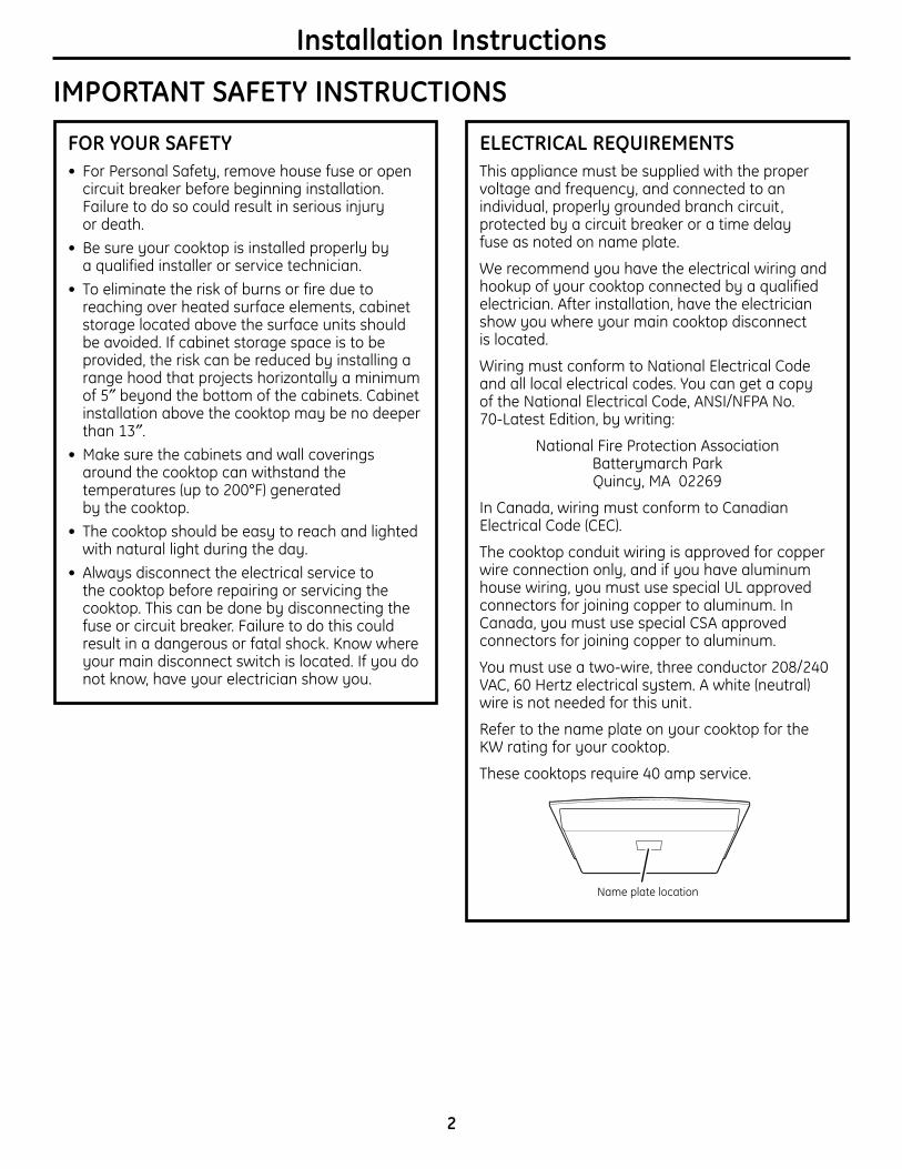
MONOGRAM INDUCTION COOKTOPAND MONOGRAM DOWNDRAFT VENTCOMBINATION INSTALLATION ONLY.The installation of the downdraft vent with this cooktop requires careful consideration. Both the cooktop and the vent must be installedaccording to each specific installation instruction.
BASE CABINET REQUIREMENTSThe combined installation will fit in a standard 24″ deep base cabinet. Use a 30″ or wider basecabinet.
– The vent housing, blower and ductwork willoccupy the base cabinet.
COOKTOP REQUIREMENTSThe countertop must have a deep flat surface toaccommodate the cooktop and vent. Countertopswith a rolled front edge and backsplash will notprovide the flat surface area required.
• Review the illustration to determine the countertopsurface requirements.
– All cutout clearances for this installation must be observed.
22-3/8″cutoutdepth
19-5/8″cooktopcutoutdepth
2-3/4″ 1/8″gap
1-3/4″ min. cooktopcutout to rear verticalcombustible surface
23-1/2″ SS23-3/8″ Black
total flat surfacerequired at center
1-3/4″ min. cutout towall, both sides2-1/2″ min. clearance
to cutout
Front edge of countertop
1-1/32″ cooktop overlap at center
28-1/2″ cooktop and vent area cutout
29-7/8″ SS29-3/4″ Black
3/4"
22-3/4" Inside22" to Support Rail
2-1/2" toCutout 1-7/8"
3/4" Thick Support Rail
20-1/16"
Vent
″
20-3/8″″
″″
″
″

6
Installation Instructions
INSTALLING OPTIONS
COOKTOP INSTALLATION OVER A GE OR GE MONOGRAM SINGLE OVENThese cooktops may be installed over a singleoven. Both the cooktop and the oven must beinstalled according to each specific installationinstruction.
– Allow 4″ Min. clearance from the top of thecountertop to the top of the oven cutout.
Use a 30″ or wider base cabinet.
• For best appearance, the cooktop should becentered over the oven.
• The baffle on the underside of the cooktop is notnecessary for this combination installation. If thebaffle is attached, remove it.
• This cooktop is only approved to be installed overthe specific models listed on the label of this unit.
POWER SUPPLYThe oven requires a separate, properly grounded 20 Amp, 3-wire 208 or 240 volt, 60 Hz power supply.The cooktop requires a separate 40 Amp, 3-wire, 208 or 240 volt, 60 Hz power supply.
23-1/2″ min.
4″ high toekick
Cooktop 28-1/2″
19-5/8″2-1/2″ min.
1-1/2″ cabinet top
4″ min. 36″countertop
heightBA
25″
Ovens Dim. A Dim. B30″ 28-1/2″ min. 27-1/4″ min.
28-5/8″ max. 27-5/16″ max.27″ 25″ min. 27-5/8″ min.
25-1/4″ max. 28-1/8″ max.
3/4″ supportplatformrequired
Must support 200 lbs.
Must matchtoekick height

ELECTRICAL CONNECTIONS
Installation Instructions
7
When connecting to a three-conductor branchcircuit, if local codes permit:
a. Connect the cooktop ground conductor leadto the brach circuit ground using a wire nut.
b. Connect the cooktop red lead to the branchcircuit red lead in accordance with localcodes, using a wire nut.
c. Connect the cooktop black lead to thebranch circuit black lead in accordance withlocal codes, using a wire nut. If the residence red, black or white leads are aluminum conductors, see WARNING.
d. Install Junction Box Cover.
NEW CONSTRUCTION AND BRANCH CIRCUIT CONNECTION
When making the wireconnections, use theentire length of conduitprovided. The conduitmust not be shortened(unless required by localcodes). The conduit lengthis 4 ft. With the cooktop inplace, open the front ofthe cabinet door. Insertthe wires from the conduitthrough the opening ofthe junction box. The conduit strain relief clampmust be securely attached to the junction box andthe flexible conduit must be securely attached tothe clamp.•When installing in new construction, or• When installing in a mobile home, or•When installing in a recreational vehicle, or• When local codes do not permit grounding
through neutral:a. Insert conduit through strain relief and tighten.b. Attach the appliance grounding lead (green
or bare copper) in accordance with local codes. If the residence grounding conductor isaluminum, see WARNING.
Ground Wire
Junction Box Cover
Junction Box Cover
Ground and NeutralWires
WARNING: Improper connectionof aluminum house wiring to copper
leads can result in an electrical hazard orfire. Use only connectors designed forjoining copper to aluminum and follow themanufacturer’s recommended procedureclosely.
THREE-CONDUCTOR BRANCH CIRCUITCONNECTION
Install junction boxso that it can bereached throughthe front of the
cabinet.
16″Min.
Strain Relief

8
INSTALLING THE COOKTOP
Installation Instructions
PROTECT SURFACE OF COOKTOPPlace a towel or tablecloth onto the countertop.Lay the cooktop upside down onto the protectedsurface.
1 ATTACH FOAM TAPEApply the foam tape around the outer edge of theglass. Do not overlap the foam tape.
NOTE: On stainless steel models, apply foam tapeon the sides and rear.
3
Bottom of Cooktop
Cloth under Cooktop
Bottom of Cooktop
Foam Tape
CooktopGlass
INSTALL HOLD-DOWN BRACKETSStart one screw through the bracket and into thecooktop. (Both sides.) Do not tighten. Turn thebracket inwards to avoid interference whendropping the cooktop into the countertop.
4INSTALL BAFFLESecure the baffle to the cooktop with screws.
NOTE: Do not install the baffle when the cooktop is installed over a single oven.
2

Installation Instructions
9
INSERT COOKTOP INTO CUTOUTInsert the cooktop centered into the cutout opening.Make sure the front edge of the countertop isparallel to the cooktop. Make final check that allrequired clearances are met.
5
Cooktop
ATTACH HOLD-DOWN BRACKETSTO CABINET
Open the cabinet door. Install the second screwthrough the bracket and tighten. Then tighten thefirst screw. Install thumbscrew until it touches thebottom of the countertop.
IMPORTANT: Turn the thumbscrew until it touchesthe bottom of the countertop. Do not overtighten.
6
Cooktop Countertop

10
Installation Instructions
CHECKLISTS
PRE-TEST CHECKLIST
Remove all protective film, if present, and anystickers.
Check to be sure that all wiring is secure andnot pinched or in contact with moving parts.
Check level of appliance.
Check that the cooktop is properly grounded.D
C
B
A
1 OPERATION CHECKLIST
Remove all items from the top of the cooktop surface.
Turn on the power to the cooktop.(Refer to your Owner’s Manual.) Verify that allsurface burners operate properly.
Check that the circuit breaker is not trippednor the house fuse blown.
Check that conduit is securely connected tothe junction box.
See Owner’s Manual for troubleshooting list.
NOTE TO ELECTRICIAN:The power leads supplied with this appliance areUL recognized for connections to larger gaugehousehold wiring. The insulation of these leads is rated at temperatures much higher than thetemperature rating of household wiring. Thecurrent carrying capacity of a conductor isgoverned by the wire gauge and also thetemperature rating of the insulation around the wire.
NOTE: ALUMINUM WIRING• WARNING:
IMPROPER CONNECTION OF ALUMINUMHOUSE WIRING TO THE COPPER LEADS CANRESULT IN A SERIOUS PROBLEM.
• Splice copper wires to aluminum wiring using special connectors designed and ULapproved for joining copper to aluminumand follow the manufacturer’s recommendedconnector procedure closely.
NOTE: Wire used, location and enclosure ofsplices, etc., must conform to good wiringpractice and local codes.
E
D
C
B
A
2