Embed Size (px)
Citation preview
INSTALL INSTRUCTIONS C-TM-DUR
HEAVY DUTY TUNNEL PLATE 2004-2009 DODGE DURANGO
TOOLS REQUIRED:
Metric Socket Set Screwdriver Set
Standard Socket Set Tape Measure
Ratcheting Wrench Open-End Wrench Set
HARDWARE:
QTY DESCRIPTION PART #
6 ¼-20 x ½” Hex head bolts GSM33000
4 ¼-20 x 3/4” Hex head bolts GSM33001
4 ¼-20 Serrated nuts GSM30023
14 ¼-20 Hex head nuts GSM30005
14 ¼” Lock washers GSM31026
8 ¼” Flat washers GSM31005
2 10-24 x 3/8” Machine screw GSM33116
4 #8 x ¾” Oval head sheet metal screws GSM33175
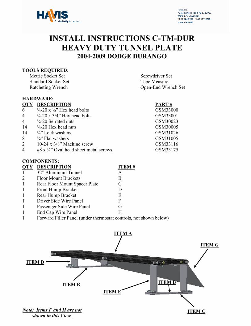
COMPONENTS:
QTY DESCRIPTION ITEM #
1 32” Aluminum Tunnel A
2 Floor Mount Brackets B
1 Rear Floor Mount Spacer Plate C
1 Front Hump Bracket D
1 Rear Hump Bracket E
1 Driver Side Wire Panel F
1 Passenger Side Wire Panel G
1 End Cap Wire Panel H
1 Forward Filler Panel (under thermostat controls, not shown below)
ITEM A
ITEM C
ITEM E
ITEM D
ITEM G
ITEM B ITEM B
Note: Items F and H are not
shown in this View.

C-TM-DUR_INST_6-09.docx6-09 2
IMPORTANT PLEASE READ PRIOR TO INSTALLATION: The 2004 Dodge Durango’s
have air bag deployment sensors built into the seat bases. Loosening the seat bolts is not
recommended by the manufacture and will create a code (airbag light on) in the onboard computer
system. This will require the vehicle to be returned to a DaimlerChrysler authorized service center
for recalibration. The C-TM-DUR mounting system makes it possible to mount consoles and
computer mounts with out the need to use seat bolts. The kit comes complete with Tunnel, mounting
brackets, and side and rear panels to give the installation a clean and professional appearance.
SUB ASSEMBLY:
1. Remove OEM console.
• (6)-Metric Hex Head Screws.
• Disconnect Rear Climate controls and 12v power outlet.
2. Move OEM harness to attach Front Floor Mount Bracket.
3. Mount Hump Brackets to Tunnel at locations shown below.
• Slide ¼-20 X ½” Hex Head Bolts in Trak
• Attach Front and Rear Hump Brackets using ¼-20 Serrated Nuts.
Note: You may locate the tunnel Hump Brackets in an alternate location to accommodate the job
specifications.
INSTALLATION:
1. FLOOR MOUNT BRACKETS:
• Move Harness mentioned in sub assembly and
mount Front Floor Bracket using OEM screws
removed earlier.
• Place Rear Floor Mount Spacer Plate. Then
mount Rear Floor Bracket using OEM screws
removed earlier.
• With Floor Brackets tight, place Tunnel and
Hump Bracket assembly so slots in Hump
Brackets line up with Pem Studs in Floor
Brackets.
7 ¾” FLUSH
Front
Hump Rear
Hump
Move Harness OEM Screws
Front Floor Bracket

C-TM-DUR_INST_6-09.docx6-09 3
2. WIRE PANELS:
• Slide (6) ¼-20 Hex Head Nuts into side of Tunnel.
Note: (3) ¼-20 Nuts per side for wire panels. If mounting other equipment to the Tunnel, you must determine
quantity and location prior to installation of Wire Panels.
• Attach Driver and Passenger Wire Panels using ¼-20 x ½” Hex Head Bolts and ¼”
Flat Washers.
• Attach Rear End Cap to the Tunnel using (2) 10-
24 x 3/8” Phillips Head Screws.
• Be sure to slide all necessary hardware into the
Tunnel prior to mounting Wire Panels and End
Cap.
• Attach forward filler located under thermostat
controls using #8 x ¾” Black oval head sheet
metal screws.
• Position forward filler panel as shown to the right.
• Attach using (4) #8 x ¾” black sheet metal
screws.
Front Hump
Bracket
Rear Hump
Bracket
Driver and Passenger
Wire Panels
End Cap
#8 x ¾”
Screws