Embed Size (px)
Citation preview
Dynamore GmbH
Industriestraße 2
70565 Stuttgart
http://www.dynamore.de
Instability and Failure Prediction for Sheet
Metal Forming Applications with LS-DYNA
André Haufe
LS-Dyna Info-Day 2011 – DYNAmore – Stuttgart – A. Haufe

2 LS-DYNA info-Day 2011 – Stuttgart – A. Haufe
Motivation
3 LS-DYNA info-Day 2011 – Stuttgart – A. Haufe
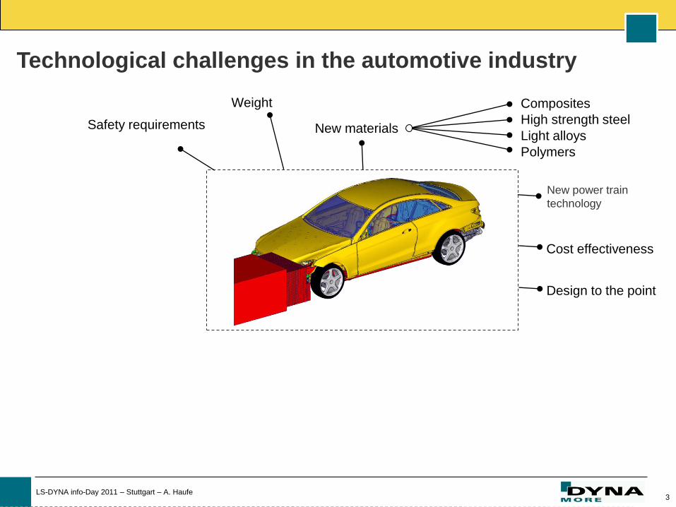
Weight Composites
High strength steel
Light alloys
Polymers
Safety requirements
Cost effectiveness
New materials
Design to the point
New power train
technology
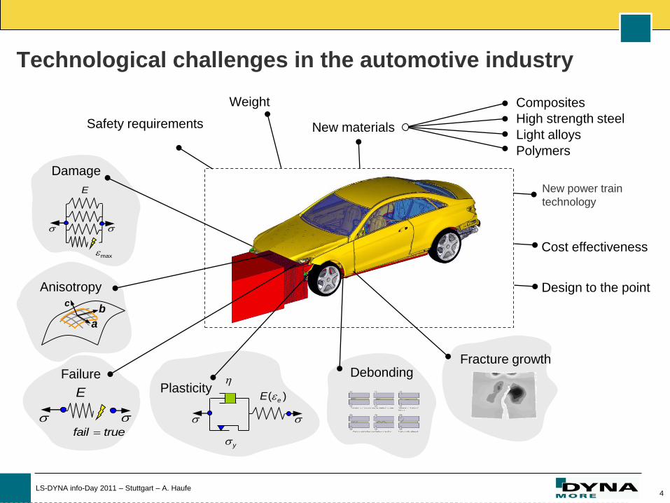
Technological challenges in the automotive industry
4 LS-DYNA info-Day 2011 – Stuttgart – A. Haufe
Technological challenges in the automotive industry
Damage
max
E
Failure
fail true
E
Anisotropy c
a
b
( )eE
y
Fracture growth Debonding
Weight Composites
High strength steel
Light alloys
Polymers
Safety requirements
Cost effectiveness
New materials
Design to the point
New power train
technology
Plasticity
5 LS-DYNA info-Day 2011 – Stuttgart – A. Haufe
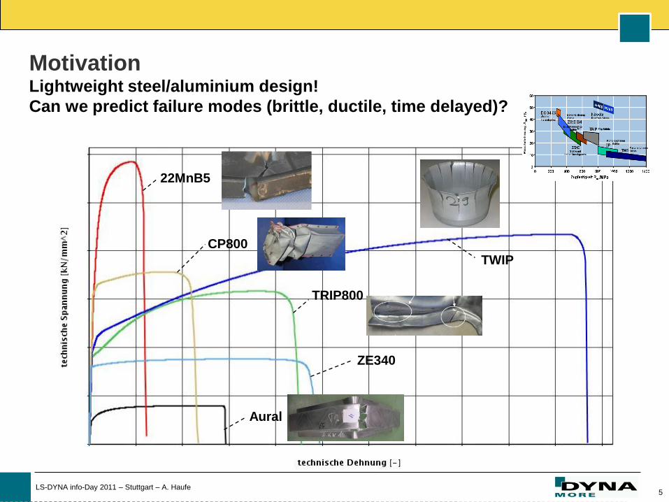
Motivation Lightweight steel/aluminium design!
Can we predict failure modes (brittle, ductile, time delayed)?
22MnB5
CP800
TRIP800
ZE340
Aural
TWIP
6 LS-DYNA info-Day 2011 – Stuttgart – A. Haufe
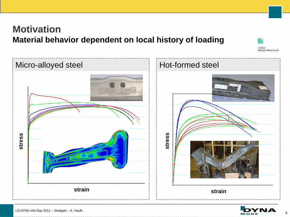
Micro-alloyed steel Hot-formed steel
Motivation Material behavior dependent on local history of loading
0
200
400
600
800
1000
1200
1400
1600
1800
0,00 0,05 0,10 0,15 0,20
technisch
te
chnis
ch
[MPa]
MN1-Rz-S1
MN1-Rz-S2
MN1-Rz-S3
MN1-Rz-S4
MN1-Rz-S5
MN1-Rz-S6
MN1-Rz-S7
MN1-Rz-S8
MN1-Rz-S9
MN1-Rz-S10
MN1-Rz-S11
MN1-Rz-S12
Technische Sigma-Epsilon-Kurve
0
100
200
300
400
500
600
700
800
900
0.00 0.10 0.20 0.30 0.40 0.50 0.60 0.70
te
ch
nis
ch
[M
Pa]
QH2-1-Fz-S1
QH2-1-Fz-S2
QH2-1-Fz-S3
QH2-1-Fz-S4
QH1-Fz-S1L
QH1-Fz-S1Q
QH1-Fz-S1D
Technische Sigma-Epsilon-Kurve
str
es
s
str
es
s
strain strain

7 LS-DYNA info-Day 2011 – Stuttgart – A. Haufe
Mapping
Forming simulation
Closing the process chain: Standard materials / state of the art
v. Mises or Gurson model
Strain rate dependency
Isotropic hardening
Damage evolution
Failure models
(mapping of damage variable)
II
I
III
Hill based models
Anisotropiy of yield surface
Kinematic/Isotropic hardening
State of the art: Failure by FLD
(post-processing)
NEW: Computation of damage
(GISSMO)
II
IIII
II
I
III
Crash simulation
8 LS-DYNA info-Day 2011 – Stuttgart – A. Haufe
Preliminary considerations
for plane stress

9 LS-DYNA info-Day 2011 – Stuttgart – A. Haufe
Plane stress condition
Principle axis
0
0
0
3
2
1
σ0
),(
),(
3
2
1
Plane stress
1
1
2
1
0 0
0 0
0 0 0
1 ( 1)vm
k
k k
σ1
12 k
Definition of stress triaxiality:
11
2
1
( 1) ( 1)sign( )
3 1 ( 1)3 1 ( 1)vm
p k k
k kk k
Parameterised
xx
yyxy
yx
Typical discretization with shell elements:
10 LS-DYNA info-Day 2011 – Stuttgart – A. Haufe
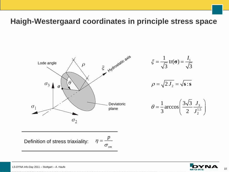
Haigh-Westergaard coordinates in principle stress space
1
2
3
1.5
2
1tr( )
3 3
2 :
1 3 3arccos
3 2
I
J
J
J
σ
s s
Deviatoric
plane
Lode angle
vm
p
Definition of stress triaxiality:
11 LS-DYNA info-Day 2011 – Stuttgart – A. Haufe
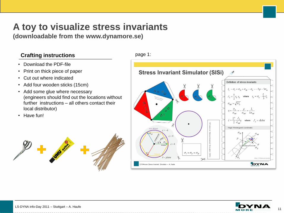
A toy to visualize stress invariants (downloadable from the www.dynamore.se)
• Download the PDF-file
• Print on thick piece of paper
• Cut out where indicated
• Add four wooden sticks (15cm)
• Add some glue where necessary
(engineers should find out the locations without
further instructions – all others contact their
local distributor)
• Have fun!
Crafting instructions page 1:
12 LS-DYNA info-Day 2011 – Stuttgart – A. Haufe
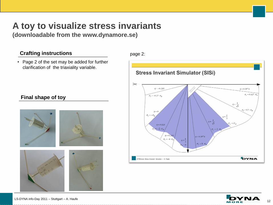
A toy to visualize stress invariants (downloadable from the www.dynamore.se)
• Page 2 of the set may be added for further
clarification of the triaxiality variable.
Crafting instructions page 2:
Final shape of toy
13 LS-DYNA info-Day 2011 – Stuttgart – A. Haufe
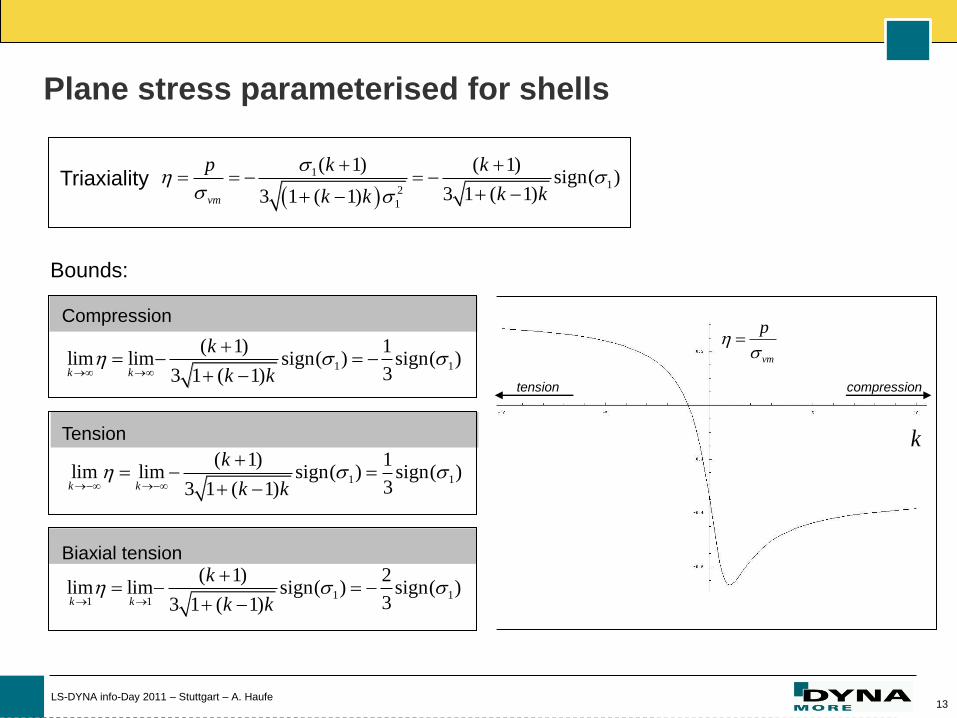
Plane stress parameterised for shells
Triaxiality
11
2
1
( 1) ( 1)sign( )
3 1 ( 1)3 1 ( 1)vm
p k k
k kk k
Bounds:
k
vm
p
1 1
( 1) 1lim lim sign( ) sign( )
33 1 ( 1)k k
k
k k
1 1
( 1) 1lim lim sign( ) sign( )
33 1 ( 1)k k
k
k k
1 11 1
( 1) 2lim lim sign( ) sign( )
33 1 ( 1)k k
k
k k
Compression
Biaxial tension
Tension
tension compression
14 LS-DYNA info-Day 2011 – Stuttgart – A. Haufe
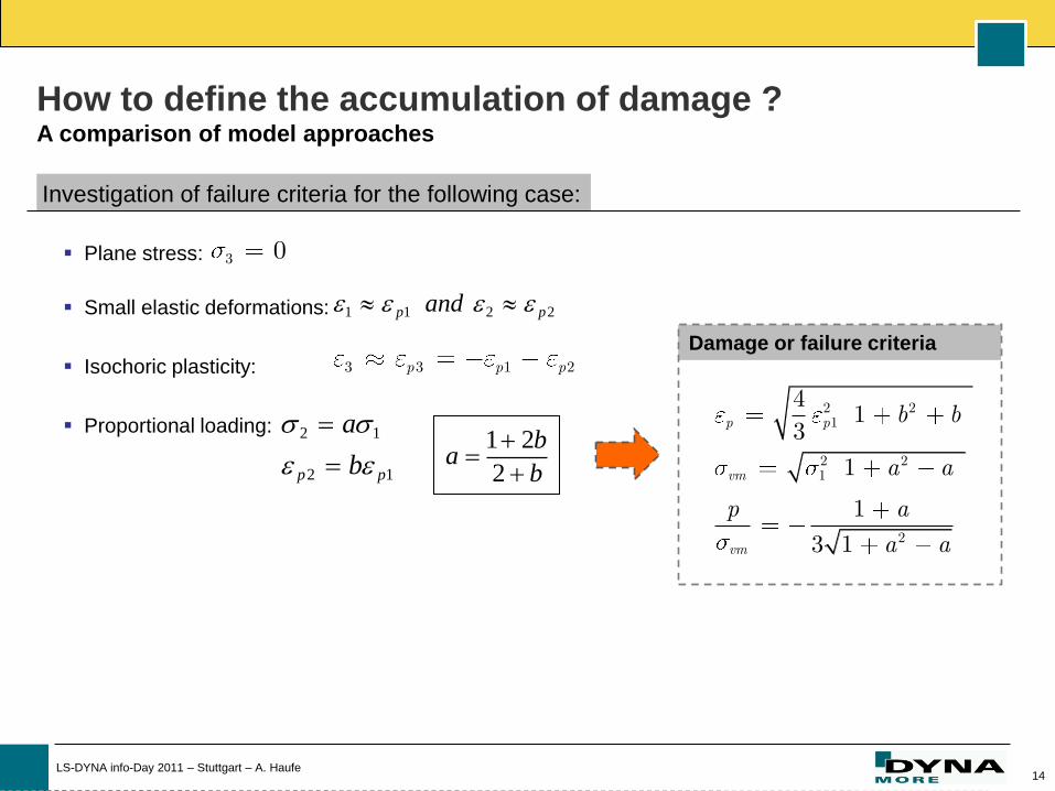
How to define the accumulation of damage ? A comparison of model approaches
Investigation of failure criteria for the following case:
Plane stress:
Small elastic deformations:
Isochoric plasticity:
Proportional loading:
3 0
1 1 2 2p pand
2 1
2 1p p
a
b
3 3 1 2p p p
1 2
2
ba
b
2 21
2 21
2
41
3
1
1
3 1
p p
vm
vm
b b
a a
p a
a a
Damage or failure criteria
15 LS-DYNA info-Day 2011 – Stuttgart – A. Haufe
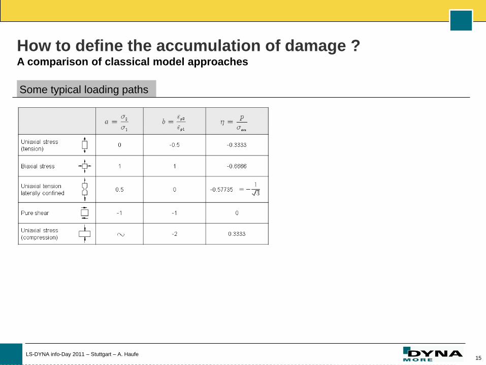
How to define the accumulation of damage ? A comparison of classical model approaches
Some typical loading paths
16 LS-DYNA info-Day 2011 – Stuttgart – A. Haufe
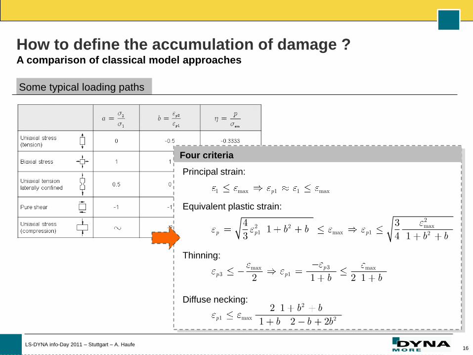
How to define the accumulation of damage ? A comparison of classical model approaches
Some typical loading paths
1 max 1 1 max
2max2 2
1 max 1 2
3max max3 1
2
1 max 2
4 31
3 4 1
2 1 2 1
2 11 2 2
p
p p p
pp p
p
b bb b
b b
b bb b b
Four criteria
Principal strain:
Equivalent plastic strain:
Thinning:
Diffuse necking:
17 LS-DYNA info-Day 2011 – Stuttgart – A. Haufe
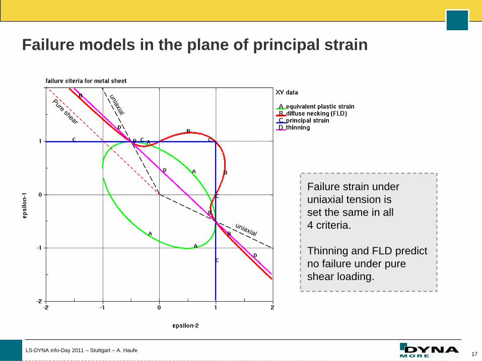
Failure models in the plane of principal strain
Failure strain under
uniaxial tension is
set the same in all
4 criteria.
Thinning and FLD predict
no failure under pure
shear loading.
18 LS-DYNA info-Day 2011 – Stuttgart – A. Haufe
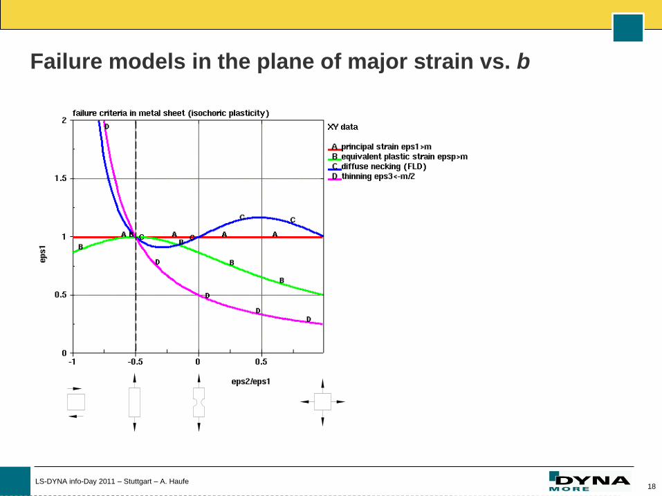
Failure models in the plane of major strain vs. b
19 LS-DYNA info-Day 2011 – Stuttgart – A. Haufe
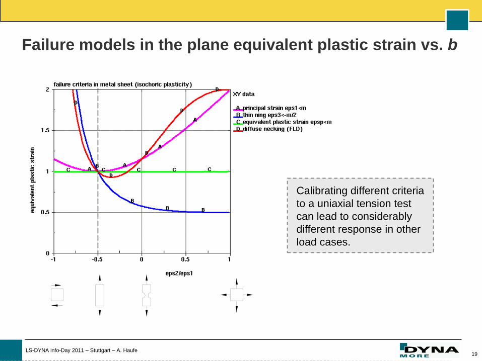
Failure models in the plane equivalent plastic strain vs. b
Calibrating different criteria
to a uniaxial tension test
can lead to considerably
different response in other
load cases.
20 LS-DYNA info-Day 2011 – Stuttgart – A. Haufe
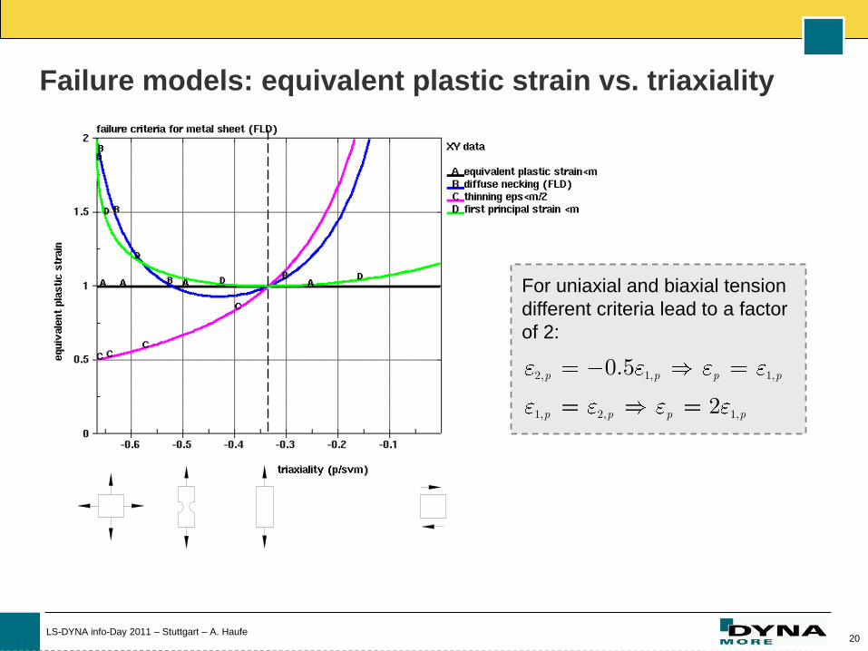
Failure models: equivalent plastic strain vs. triaxiality
2, 1, 1,
1, 2, 1,
0.5
2
p p p p
p p p p
For uniaxial and biaxial tension
different criteria lead to a factor
of 2:
21 LS-DYNA info-Day 2011 – Stuttgart – A. Haufe
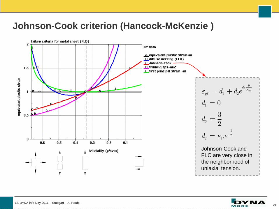
Johnson-Cook criterion (Hancock-McKenzie )
3
1 2
1
3
12
2 1
0
32
vm
pd
pf
f
d d e
d
d
d e
Johnson-Cook and
FLC are very close in
the neighborhood of
uniaxial tension.
22 LS-DYNA info-Day 2011 – Stuttgart – A. Haufe
Parametrized for 3D stress space
23 LS-DYNA info-Day 2011 – Stuttgart – A. Haufe
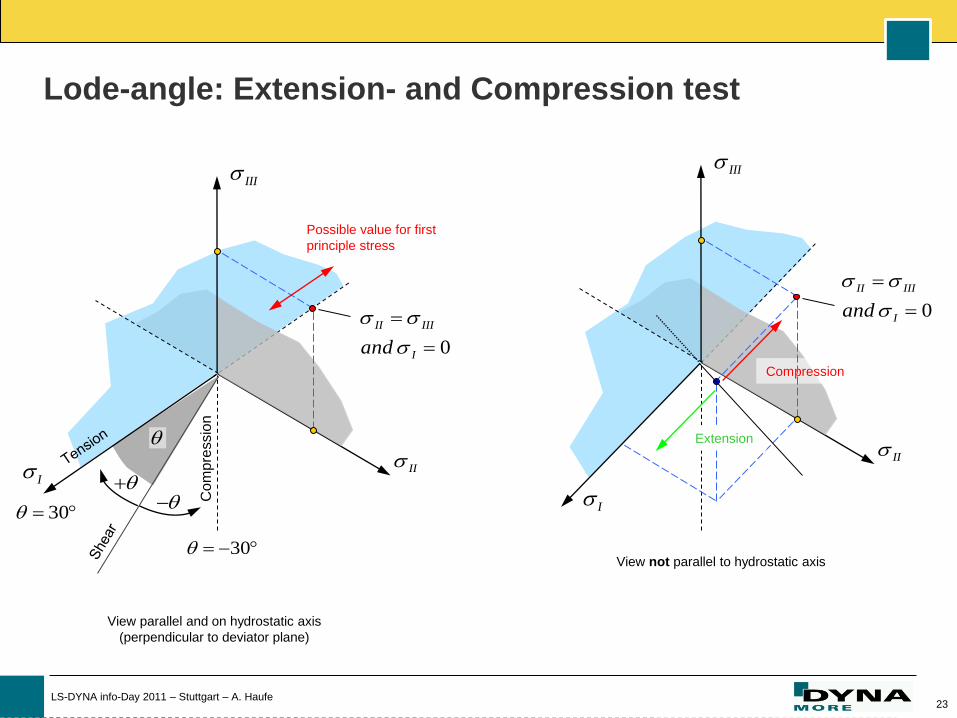
Lode-angle: Extension- and Compression test
I
III
II
0
II III
Iand
View parallel and on hydrostatic axis
(perpendicular to deviator plane)
Possible value for first
principle stress
I
III
II
Compression
0
II III
Iand
View not parallel to hydrostatic axis
Extension
30
30
Com
pre
ssio
n

24 LS-DYNA info-Day 2011 – Stuttgart – A. Haufe
1 01
1
1
0 0
10 04
10 0
4
1
1
0 0
0 0
0 0 0
1
1
0 0
10 02
0 0 0
1 0 0
0 0 0
0 0 0
1
1
0 0
0 0 0
0 0
1
0 0 0
0 0 0
0 0
1
1
1
0 0
0 0
10 0
2
3D-Stress state parameterised for volume elements
compression
extension
vm
p
F
25 LS-DYNA info-Day 2011 – Stuttgart – A. Haufe
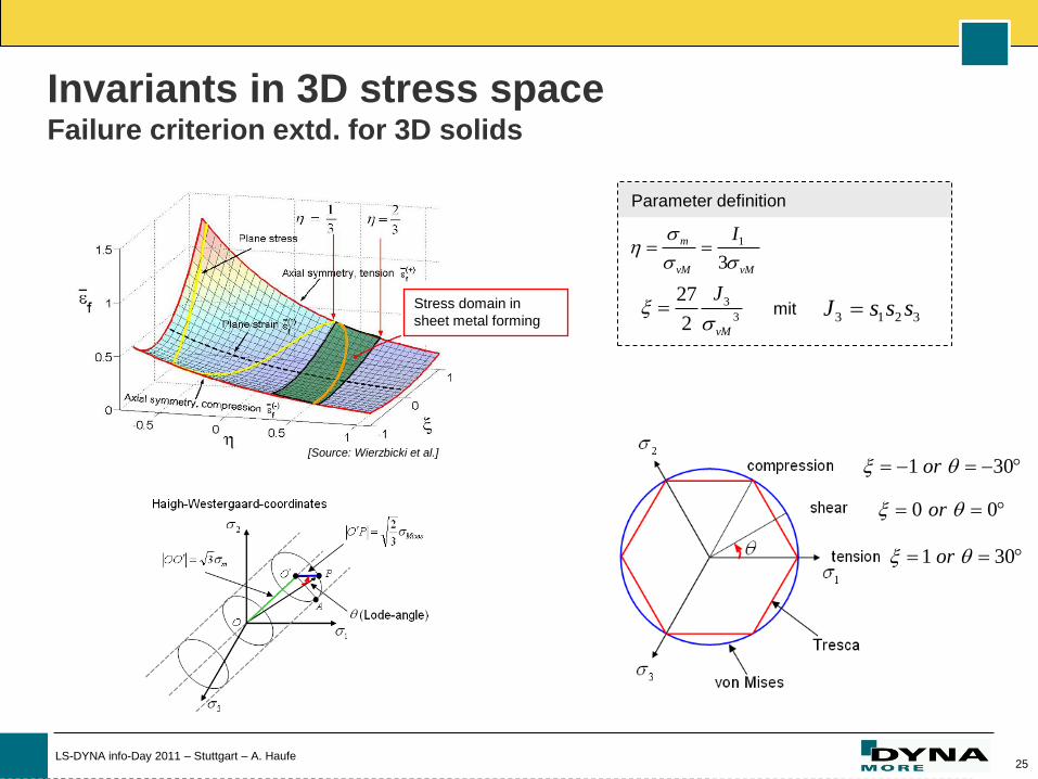
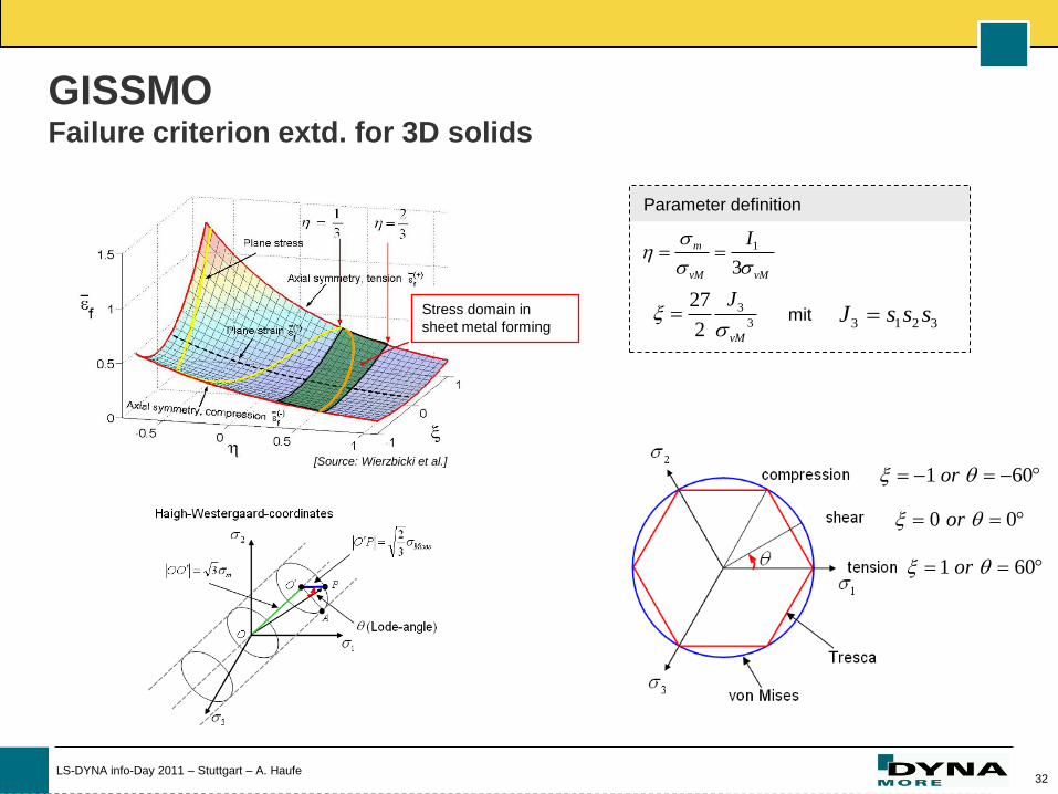
Parameter definition
1
3
m
vM vM
I
3
3
27
2 vM
J
3 1 2 3J s s smit
[Source: Wierzbicki et al.]
Stress domain in
sheet metal forming
Invariants in 3D stress space Failure criterion extd. for 3D solids
1 30or
0 0or
1 30or
26 LS-DYNA info-Day 2011 – Stuttgart – A. Haufe
Failure Prediction for UHSS:
Adding some damage

27 LS-DYNA info-Day 2011 – Stuttgart – A. Haufe
Mapping
Forming simulation
Closing the process chain: Standard materials / state of the art
v. Mises or Gurson model
Strain rate dependency
Isotropic hardening
Damage evolution
Failure models
(mapping of damage variable)
II
I
III
Hill based models
Anisotropiy of yield surface
Kinematic/Isotropic hardening
State of the art: Failure by FLD
(post-processing)
NEW: Computation of damage
(GISSMO)
II
IIII
II
I
III
Crash simulation
28 LS-DYNA info-Day 2011 – Stuttgart – A. Haufe
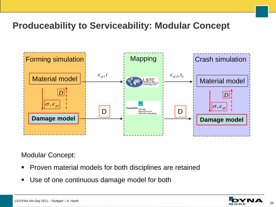
Produceability to Serviceability: Modular Concept
Damage model
Material model Material model 00, , tpl
pl ,
Mapping
tpl ,
D D Damage model
pl ,
Forming simulation Crash simulation
D D
Modular Concept:
Proven material models for both disciplines are retained
Use of one continuous damage model for both
29 LS-DYNA info-Day 2011 – Stuttgart – A. Haufe
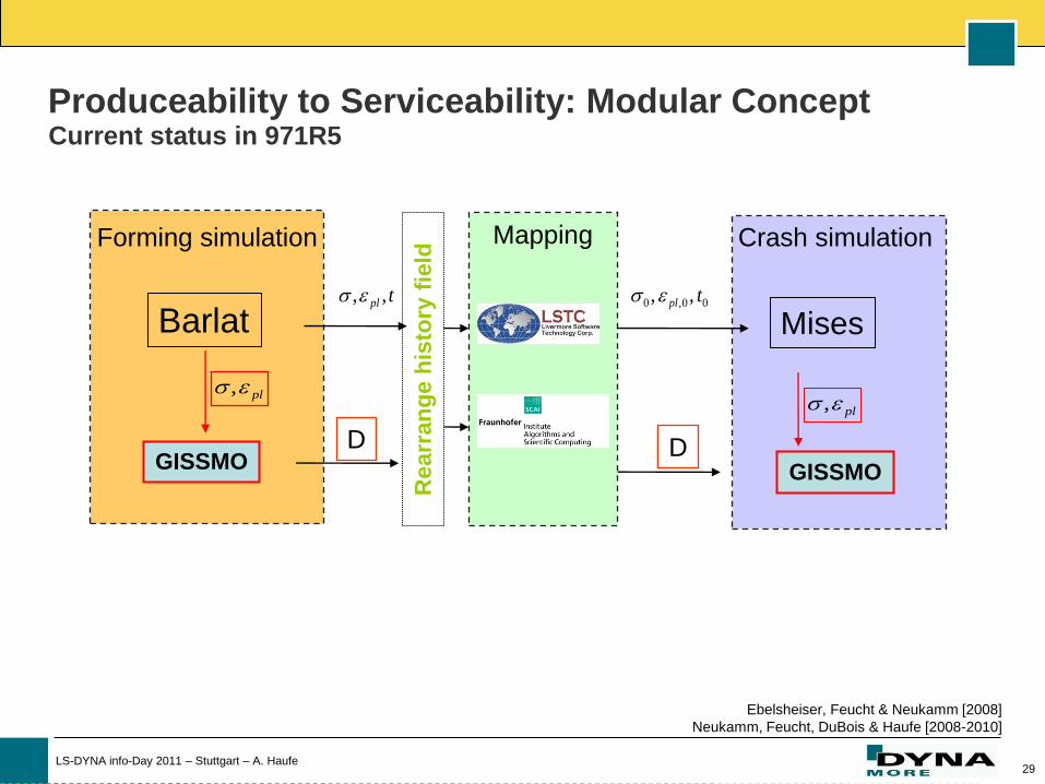
GISSMO
Barlat Mises 00,0 ,, tpl
pl ,
Mapping
tpl ,,
Re
arr
an
ge
his
tory
fie
ld
D D GISSMO
pl ,
Forming simulation Crash simulation
Ebelsheiser, Feucht & Neukamm [2008]
Neukamm, Feucht, DuBois & Haufe [2008-2010]
Produceability to Serviceability: Modular Concept Current status in 971R5
30 LS-DYNA info-Day 2011 – Stuttgart – A. Haufe
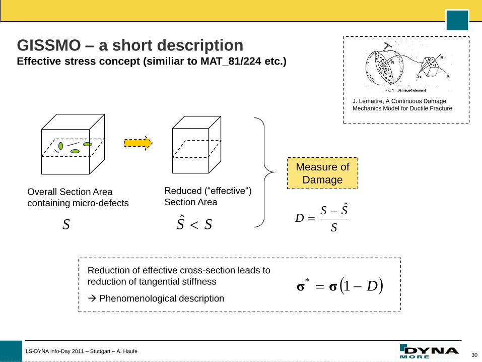
J. Lemaitre, A Continuous Damage
Mechanics Model for Ductile Fracture
Overall Section Area
containing micro-defects
Reduced (“effective“)
Section Area
SS ˆS S
SSD
ˆ
Measure of
Damage
Reduction of effective cross-section leads to
reduction of tangential stiffness
Phenomenological description D 1*
σσ
GISSMO – a short description Effective stress concept (similiar to MAT_81/224 etc.)
31 LS-DYNA info-Day 2011 – Stuttgart – A. Haufe
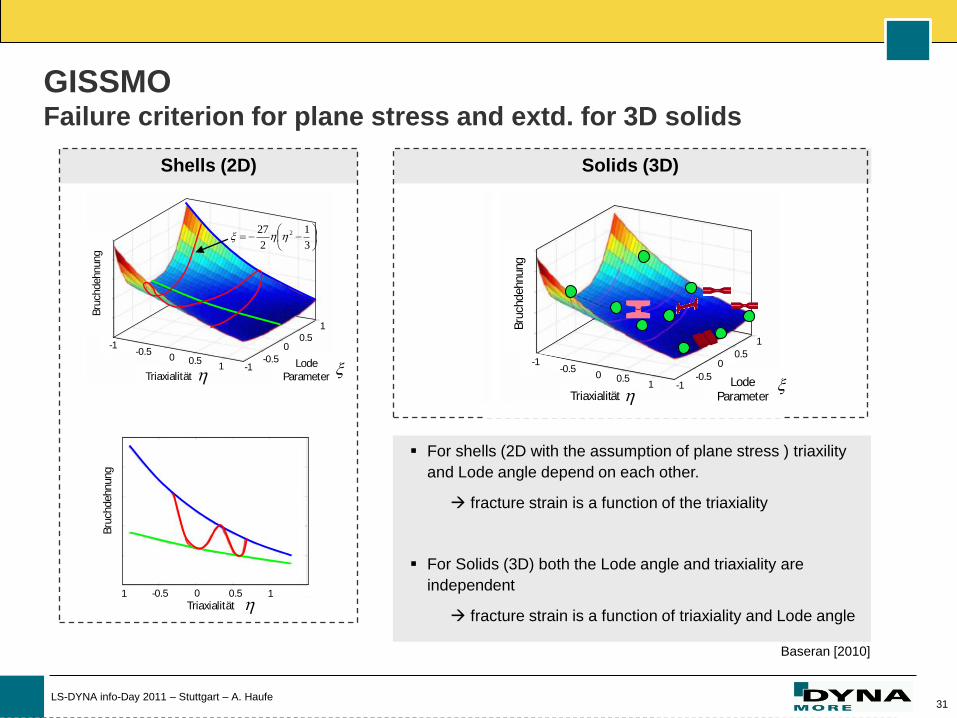
GISSMO Failure criterion for plane stress and extd. for 3D solids
Lode
Parameter-1
1
0
-0.5
0.5
0.50
-1-0.5
1Triaxialität
Bru
chdehnung
Triaxialität
Bru
chdehnung
-0.5 0 0.5 11
For shells (2D with the assumption of plane stress ) triaxility
and Lode angle depend on each other.
fracture strain is a function of the triaxiality
For Solids (3D) both the Lode angle and triaxiality are
independent
fracture strain is a function of triaxiality and Lode angle
Shells (2D) Solids (3D)
Lode Parameter
-1
1
0
-0.5
0.5
0.50
-1-0.5
1
Triaxialität
Bru
chdehnung
Baseran [2010]
3
1
2
27 2
32 LS-DYNA info-Day 2011 – Stuttgart – A. Haufe
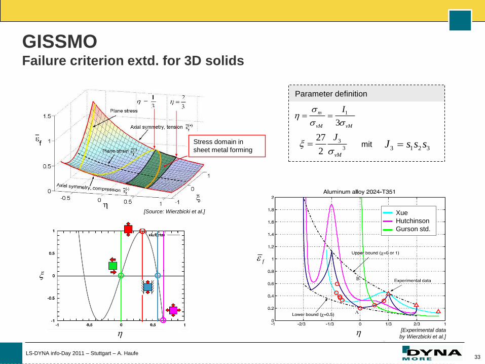
Parameter definition
1
3
m
vM vM
I
3
3
27
2 vM
J
3 1 2 3J s s smit
[Source: Wierzbicki et al.]
Stress domain in
sheet metal forming
GISSMO Failure criterion extd. for 3D solids
1 60or
0 0or
1 60or
33 LS-DYNA info-Day 2011 – Stuttgart – A. Haufe
Parameter definition
1
3
m
vM vM
I
3
3
27
2 vM
J
3 1 2 3J s s smit
[Source: Wierzbicki et al.]
Stress domain in
sheet metal forming
Xue
Hutchinson
Gurson std.
Xue
Hutchinson
Gurson std.
f
[Experimental data
by Wierzbicki et al.]
GISSMO Failure criterion extd. for 3D solids
34 LS-DYNA info-Day 2011 – Stuttgart – A. Haufe
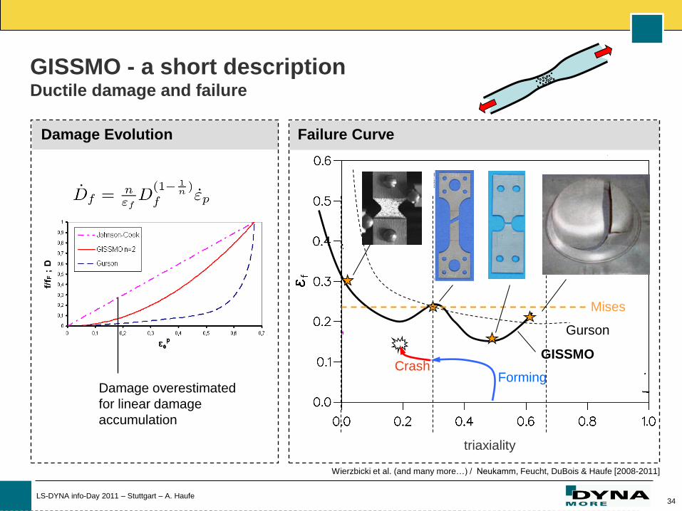
Gurson
Mises
Forming Crash
GISSMO
Damage Evolution
Damage overestimated
for linear damage
accumulation
Failure Curve
GISSMO - a short description Ductile damage and failure
triaxiality
Wierzbicki et al. (and many more…) / Neukamm, Feucht, DuBois & Haufe [2008-2011]
35 LS-DYNA info-Day 2011 – Stuttgart – A. Haufe
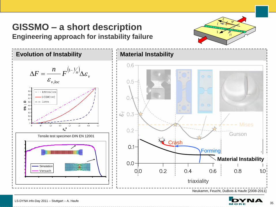
Gurson
Mises
Forming
Crash
Evolution of Instability Material Instability
Material Instability
v
n
locv
Fn
F
11
,
Flachzugprobe DIN EN 12001
0,00
0,05
0,10
0,15
0,20
0,25
0,30
0,35
0,40
0,45
0,50
0,00 0,05 0,10 0,15 0,20 0,25 0,30
Simulation
Versuch
Tensile test specimen DIN EN 12001
GISSMO – a short description Engineering approach for instability failure n
t
1
2
triaxiality
Neukamm, Feucht, DuBois & Haufe [2008-2011]

36 LS-DYNA info-Day 2011 – Stuttgart – A. Haufe
GISSMO – a short description Inherent mesh-size dependency of results in the post-critical region
0,0
0,2
0,4
0,0 0,1 0,2 0,3 0,4 0,5
Engineering Strain
En
gin
ee
rin
g S
tre
ss
Experiment
0,5mm
1mm
2,5mm
Simulations of tensile test specimen with different mesh sizes
Regularization of
mesh-size dependency
element size
Influence of damage in
postcritical region

37 LS-DYNA info-Day 2011 – Stuttgart – A. Haufe
DMGTYP: Flag for coupling (Lemaitre)
D 1*
DCRIT, FADEXP: Post-critical behavior
0
0
True Strain
Tru
e S
tre
ss
GISSMO dmgtyp2
MAT_024
0
0True Strain
Tru
e S
tre
ss
m=2
m=5
m=8
FADEXP
CRIT
CRIT
D
DD
11*
GISSMO – a short description Generalized Incremental Stress State dependent damage MOdel

38 LS-DYNA info-Day 2011 – Stuttgart – A. Haufe
Flachzugproben DIN EN 10002
0,00
0,10
0,20
0,30
0,40
0,50
0,60
0,00 0,10 0,20 0,30 0,40
Mini-Flachzugproben ungekerbt
0,00
0,10
0,20
0,30
0,40
0,50
0,60
0,0 0,2 0,4 0,6 0,8
Mini-Flachzugproben Kerbradius 1mm
0,0
0,1
0,2
0,3
0,4
0,5
0,6
-0,10 0,10 0,30 0,50
Arcan
0
2
4
6
8
10
12
0,0 0,5 1,0 1,5
Scherzugproben Kerbradius 1mm, 0°
0,00
0,10
0,20
0,30
0,40
0,50
0,60
0,00 0,05 0,10 0,15 0,20
Scherzugproben Kerbradius 1mm, 15°
0,00
0,10
0,20
0,30
0,40
0,50
0,00 0,05 0,10 0,15 0,20
Scherzugproben Kerbradius 1mm, 15°
0,00
0,10
0,20
0,30
0,40
0,50
0,00 0,05 0,10 0,15 0,20
eps_technisch
Sig
ma_
tech
nis
ch [
GP
a]
Versuch
GISSMO
Gurson
constant (v. Mises)
Small tensile test specimen Notched tensile specimen, notch radius 1mm Shear test, inclined 15
Tensile specimen DIN EN 12001 Shear test, straight
GISSMO vs. Gurson vs. MAT_24/81 Comparison of experiments and simulations
39 LS-DYNA info-Day 2011 – Stuttgart – A. Haufe
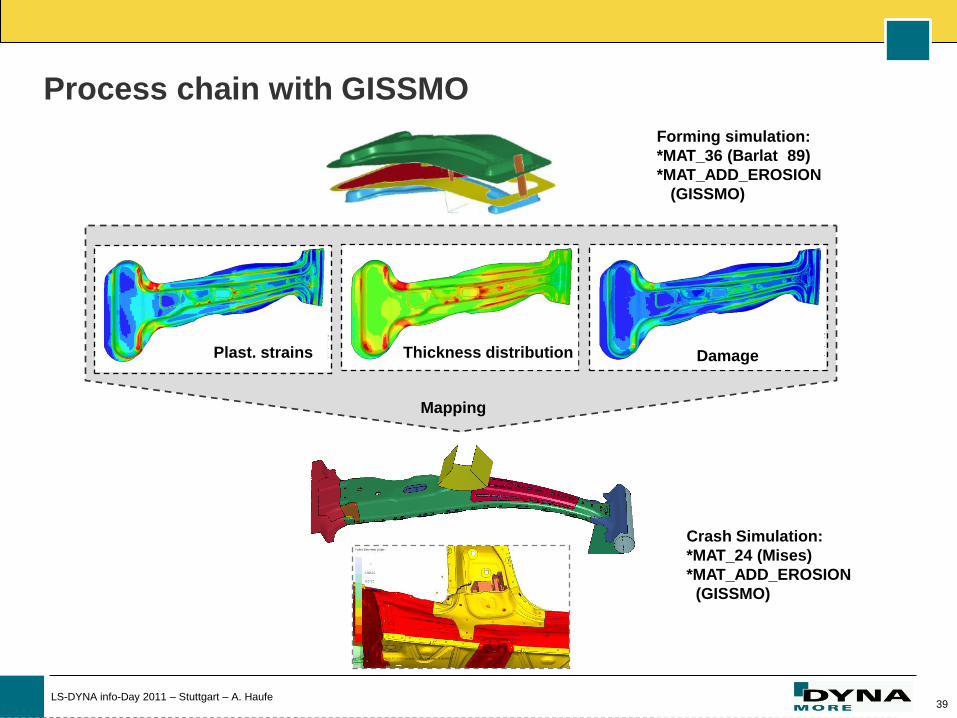
Forming simulation:
*MAT_36 (Barlat
89)
*MAT_ADD_EROSION
(GISSMO)
Crash Simulation:
*MAT_24 (Mises)
*MAT_ADD_EROSION
(GISSMO)
Plast. strains Thickness distribution Damage
Mapping
Process chain with GISSMO
40 LS-DYNA info-Day 2011 – Stuttgart – A. Haufe
Summary
Features of GISSMO:
Use of existing material models and respective parameters
Constitutive model and damage formulation are treated separately
Allows for the calculation of pre-damage for forming and crashworthiness
simulations
Characterization of materials requires a variety of tests
Offers features for a comprehensive treatment of damage
in forming simulations and allows simply carrying aver to crash analysis

41 LS-DYNA info-Day 2011 – Stuttgart – A. Haufe
Thank you for your attention!