Embed Size (px)
Citation preview

Product documentation
DALI gateway TWArt. No. 2099REGHE
ALBRECHT JUNG GMBH & CO. KGVolmestraße 158579 SchalksmühleGERMANY
Telefon: +49 2355 806-0Telefax: +49 2355 [email protected]
Issue: 20.07.201764544320

Art. No. 2099REGHE
Table of ContentsProduct definition1 4.................................................................................................................
Product catalogue1.1 4...........................................................................................................Function1.2 4..........................................................................................................................
Mounting, electrical connection and operation2 7.................................................................
Safety instructions2.1 7...........................................................................................................Device components2.2 8........................................................................................................Fitting and electrical connection2.3 9......................................................................................Commissioning2.4 13.............................................................................................................Operation2.5 14......................................................................................................................
Technical data3 20....................................................................................................................
Software description4 21..........................................................................................................
Software specification4.1 21...................................................................................................Software "DALI Gateway C0201x"4.2 23................................................................................
Scope of functions4.2.1 23.................................................................................................Notes on software4.2.2 25..................................................................................................Object table4.2.3 26...........................................................................................................
Objects for group and single devices4.2.3.1 26.............................................................Objects for scenes and effects4.2.3.2 30.......................................................................Object for emergency lighting4.2.3.3 32........................................................................Objects for general functions4.2.3.4 34.........................................................................
Functional description4.2.4 39............................................................................................Application basics4.2.4.1 39..........................................................................................
DALI system and addressing types4.2.4.1.1 39........................................................DALI emergency lighting systems4.2.4.1.2 48..........................................................ETS plug-in4.2.4.1.3 52.............................................................................................
Description of group- and device-independent functions4.2.4.2 60...............................DALI communication4.2.4.2.1 60..............................................................................DALI error messages4.2.4.2.2 62..............................................................................Status and feedbacks4.2.4.2.3 68.............................................................................Global switching status / Standby switch-off4.2.4.2.4 72..........................................Manual operation4.2.4.2.5 74....................................................................................Central function4.2.4.2.6 79.......................................................................................
Description of group and device functions4.2.4.3 80.....................................................Controlling the brightness4.2.4.3.1 80.......................................................................Controlling the colour temperature4.2.4.3.2 90.........................................................Response after a device reset4.2.4.3.3 98................................................................Supplementary function4.2.4.3.4 104........................................................................Feedback functions4.2.4.3.5 107..............................................................................Automatic switch-off4.2.4.3.6 117.............................................................................Switch-on and switch-off behaviour4.2.4.3.7 119......................................................Staircase function4.2.4.3.8 122.................................................................................Operating hours counter4.2.4.3.9 131.......................................................................
Scene function4.2.4.4 135.............................................................................................Effect function4.2.4.5 142..............................................................................................
Product documentation
Page 2 of 257
Art. No. 2099REGHE
Emergency lighting4.2.4.6 153.......................................................................................General configurations4.2.4.6.1 153.........................................................................Configurations for centrally-supplied emergency lights4.2.4.6.2 155........................
DALI commissioning4.2.4.7 161....................................................................................Starting DALI commissioning4.2.4.7.1 161...............................................................Performing DALI commissioning4.2.4.7.2 163..........................................................Exiting DALI commissioning4.2.4.7.3 178.................................................................Offline commissioning4.2.4.7.4 181..........................................................................Troubleshooting4.2.4.7.5 184....................................................................................
DALI test4.2.4.8 187......................................................................................................Delivery state4.2.4.9 195...............................................................................................
Parameters4.2.5 196..........................................................................................................General parameters4.2.5.1 196.....................................................................................Parameters for manual operation4.2.5.2 207................................................................Parameters for groups and single devices4.2.5.3 209...................................................Parameters for scenes and effects4.2.5.4 241..............................................................Parameters for emergency lights4.2.5.5 248.................................................................
Appendix5 255...........................................................................................................................
Index5.1 255...........................................................................................................................
Product documentation
Page 3 of 257

Art. No. 2099REGHE
1 Product definition1.1 Product catalogue
Product name: DALI-Gateway TW
Use: Gateway
Design: RMD (rail-mounted device)
Art. No. 2099REGHE
1.2 FunctionDALIThe DALI Gateway forms the interface between a KNX installation and a digital DALI (DigitalAddressable Lighting Interface) lighting system. The DALI Gateway allows the switching anddimming of a maximum of 64 lights with a DALI operating device (e.g. electronic ballast). Up to6 different addressing types allow group-orientated and individually-address control of DALIlights via KNX telegrams. This allows the integration of room-specific light control, for example,of open-plan offices, multipurpose spaces, production facilities, training and presentation roomsor showcases into the higher-level KNX building management. Depending on the configuration,up to 32 independent DALI groups are available for group addressing. For alternative control,these can be supplemented with 64 individually-addressable DALI device channels, asnecessary.Optionally, master control of all connected DALI components is possible (broadcast). Thismeans that there is no need to commission DALI, meaning that lighting systems with fewfunctions can be started up quickly and easily (simplified configuration without DALIcommissioning).
Colour temperature control (DALI Device Type 8)The DALI Gateway supports the control of DALI operating devices of the device type "ColourControl" (DALI Device Type 8) in the specific version "Tunable White (TW)". This makes itpossible to control the colour temperature of a lamp by means of suitable DALI operatingdevices and luminaires. The Gateway allows the colour temperature control via relative orabsolute dimming as well as via scenes and effects. The colour temperature control is largelyindependent of the brightness control and luminaire used.
DALI groups and single devicesThe DALI Gateway permits the separate feedback of the individual switching and brightnessstatuses and also of the colour temperature of the DALI groups and single devices to the KNX.In addition, the general DALI state of operation can be signalled to the KNX (error status, short-circuit, status of the supply voltage). The function features that are independently adjustable forevery light group or each single device by means of the ETS include, for example, separatelyconfigurable brightness ranges, extended feedback functions, a disabling function, oralternatively, a forced position function, separately adjustable dimming behaviour, time delays,soft dimming functions, a staircase function with supplementary functions and an operatinghours counter. Moreover, the brightness values of the groups of single devices in case of busvoltage failure or bus voltage return and after ETS programming, can be preset separately.Central switching or collective feedback of all switching states is also possible.The following functions can also be configured for operating devices that support a DALI colourtemperature control: Definition of the controllable colour temperature range by minimum andmaximum colour temperature, switch-on colour temperature definable, relative and absolutedimming of the colour temperature and feedback of the current colour temperature.Furthermore, it is also possible to automatically change the colour temperature proportionallywhen dimming the brightness. This makes it possible with little project planning to simulate a
Page 4 of 257
Product definition

Art. No. 2099REGHE
thermal radiator using almost any colour temperature controllable luminaire (perception of thelight source such as an incandescent or halogen lamp).Optionally, the assignment of DALI operating devices to programmed groups or single devicescan be supplemented by testing of the DALI device types. If testing is enabled, the plug-incompares, during assignment as part of commissioning, the device types determined by theoperating devices with the specifications by the device type parameters. Assignment can onlytake place if there is agreement. This will prevent functional incompatibilities aftercommissioning.When using the tunable white colour temperature control, the usage and testing of the DALIdevice type is intended to be unchangeable.
DALI emergency lighting systemsThe DALI Gateway can be integrated into DALI emergency lighting systems. It allowsinterference-free operation of operating devices, general lighting systems and emergencylighting operating devices of the same DALI system. The device is able to integrate standardDALI operating devices for lighting control according to IEC 62386-101 (DALI System) andIEC 62386-102 (Control-Gear) into centrally-supplied emergency lighting systems as anemergency light.
Scenes and effectsLights or light groups can optionally be integrated in up to 16 scenes, which means that pre-programmed static light scenes can be recalled by influencing the brightness and colourtemperature. If necessary, the scene values can be individually adapted and saved duringdevice operation, allowing the user to replace the presettings of the ETS.In particular, for the implementation of dynamic light scenes, it is possible to include lights orlight groups in the effect control of the DALI Gateway. Up to 16 effects are available here, eachwith up to 16 effect steps. Each effect step represents an individual light scene by influencingthe brightness and colour temperature. Time-controlled toggling of the effect steps makes theoverall effect dynamic. Brightness and colour temperature sequences can be implementedusing one or more DALI groups, but also using individual DALI devices or scenes. A timer isavailable if necessary, which means that individual effects can be started and stoppeddepending on the time and weekday.
ETS plug-inThe DALI Gateway is configured and commissioned using a plug-in embedded in the ETS. Forproject design and commissioning of this device, we recommend using the ETS5. Projectdesigning and commissioning of the device using ETS4 (from version 4.2) ETS3 from version"d" is also possible. Additional hardware or software is not required for the configuration andcommissioning of the DALI Gateway.The identification, addressing and assignment of DALI operating devices takes place in theDALI commissioning environment of the ETS plug-in. Commissioning can be prepared offline inthe parameter configuration if necessary. Offline commissioning is ideal as the preparation forlater complete commissioning, if there is no programming connection to the DALI Gateway orthe DALI operating devices, but group assignment is still to take place. This is normally the casewhen the building planning and thus also the Gateway configuration take place earlier than thecommissioning of the DALI Gateway and the DALI system.The DALI short addresses are always assigned in the parameter configuration of the singledevices and can thus be influenced. With the addition of group and device names, uniquenaming of DALI operating devices is possible in this way. Through the transmission of theunique names to the KNX building visualisation (e.g. control panels), the user is able -particularly during error diagnosis - to identify the lighting components easily.
Page 5 of 257
Product definition

Art. No. 2099REGHE
DALI compatibilityThe DALI Gateway has a compatibility mode for supporting non-DALI-conformant operatingdevices. This means that the commissioning process becomes distinctly more tolerant towardsspecific DALI commissioning parameters, which means that operating devices not fullycompliant with the DALI specification can be commissioned, possibly subject to functionalrestrictions. In addition to this, a DALI telegram rate limit can be activated in the ETS plug-in,meaning that adaptation to non-DALI-conformant operating devices is possible.
Manual operation and mountingThe operating elements (4 push-buttons) on the front panel of the device allow the DALI lightgroups or single devices to be switched on and off or dimmed in brightness by manual operationin parallel with the KNX even without bus voltage or in a non-programmed state (broadcast of allconnected DALI subscribers). This feature permits fast checking of connected loads for properfunctioning.In addition, the DALI Gateway is able to check the completeness of the operating devicesintegrated into the DALI system. This means that it is possible to detect the replacement of adefective electronic ballast with a new one. The automatic device replacement fulfils thisfunction as necessary. The Gateway then transmits the configuration data to the new electronicballast, fully automatically, without the need to carry out special commissioning. This simplifiesthe repair of a DALI system considerably.The DALI Gateway is supplied completely via the mains voltage connection and makes theDALI system voltage (typ. DC 16 V) available. The mains voltage must be switched on to controlthe DALI interface or for programming by the ETS.The device is designed for mounting on DIN rails in closed compact boxes or in distributors infixed installations.
Page 6 of 257
Product definition

Art. No. 2099REGHE
2 Mounting, electrical connection and operation2.1 Safety instructionsElectrical equipment may only be installed and fitted by electrically skilled persons. Theapplicable accident prevention regulations must be observed.Failure to observe the instructions may cause damage to the device and result in fire andother hazards.Before working on the device or exchanging the connected DALI operating devices,disconnect it from the power supply (switch off the miniature circuit breaker), otherwisethere is the risk of an electric shock.The device is not suitable for disconnection from supply voltage.The DALI control voltage is a functional extra-low voltage (FELV). On installing, ensuresafe isolation between KNX and DALI and mains voltage. A minimum distance of at least4 mm must be maintained between bus conductors and DALI/mains voltage cores.The device may not be opened or operated outside the technical specifications.
Page 7 of 257
Mounting, electrical connection and operation

Art. No. 2099REGHE
2.2 Device components
ALL
(1)
(2)
(3)
(4) (5)
(6)
Figure 1: Device components
(1) KNX connection(2) Programming button and LED (red).(3) Button field for manual control with status LEDs(4) DALI output (da+, da-)(5) Connection of mains voltage supply (L, N)(6) 7-segment display to show the DALI group or the single device selected by manual
operation. Disabled in bus operation. In addition, to display additional information:
- -: Signals DALI commissioning phase or delay after an ETS programming operation ormains voltage return.
bc: Display during manual operation in an unprogrammed status (broadcast operation).
Er: Displaying an impermissible external voltage on the DALI device connection terminals(e.g. mains voltage connected). DALI Gateway without function. The Gateway is only readyfor operation again when the error has been eliminated and initialisation has beenperformed again (mains voltage return).
LE: Signals automatic device replacement.
E: Signals an error during automatic device replacement.
Page 8 of 257
Mounting, electrical connection and operation
Art. No. 2099REGHE
2.3 Fitting and electrical connectionDANGER!Electrical shock when live parts are touched.Electrical shocks can be fatal.Before working on the device, disconnect the power supply and cover up liveparts in the working environment.
Fitting the deviceo Fit the device by snapping it onto a mounting rail in acc. with EN 60715. The screw
terminals should be at the top.i A KNX data rail is not required.i Observe the temperature range (see Technical Data) and ensure sufficient cooling, if
necessary.
Connecting the power supply for the device electronics and DALI interface
ALL
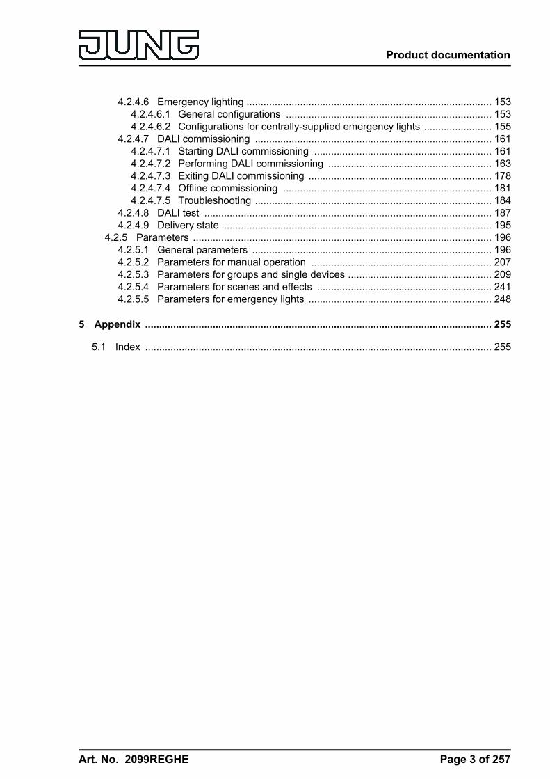
Figure 2: Electrical connection of mains voltage and the DALI interface
o Connect the mains voltage and the DALI system as shown in the connection example(figure 2).
i The DALI system voltage is a functional extra-low voltage (FELV). For this reason, theDALI interface should be treated as a cable able to carry voltage, in accordance with theinstallation instructions. The DALI Gateway supplies the system voltage (typ. DC 16 V).Carry out the installation work so that, when a DALI area is disconnected, all the mainsvoltages of the connected DALI operating device and the mains voltage supply of the DALIGateway are switched off.
i DALI devices (max.64) can be connected to various phase conductors (L1, L2, L3).
Page 9 of 257
Mounting, electrical connection and operation

Art. No. 2099REGHE
i For reasons of clarity during installation, we recommend observing the polarity of the DALIcable. Observance of the DALI polarity is always dependent on the DALI operating devicesbeing used.
o If multiple circuit breakers supply dangerous voltages to the device or load, couple theminiature circuit breakers or label them with a warning, to ensure disconnection isguaranteed.
o Connect bus line with connecting terminal.
Removing other operating unitsDALI subscribers of some manufacturers have extended functions (operation with mainsvoltage on the DALI connection). When using the DALI Gateway as a control unit in the DALIsystem, any other control sections must be removed from the installation - particularly whenrefitting existing systems.o Remove all the appropriate operating units, or ensure that there are no other control
sections (figure 3).
ALL O FF
Figure 3: Removing other operating units in the DALI system
i Other control sections could be, for example, DALI central units, DALI potentiometers orcomparable control components. These control sections must also be removed from theDALI system, in order to avoid system conflicts.
i The DALI Gateway supplies the DALI system voltage. For this reason, it is not permitted tointegrate an additional DALI power supply into the installation, in parallel to the Gateway.
i Only one DALI Gateway may be operated in a closed DALI system.
Page 10 of 257
Mounting, electrical connection and operation

Art. No. 2099REGHE
i If the DALI Gateway detects mains voltage on the DALI connection (da+ and da-terminals), then it will cease operation and signal Er in the LED display.
Operation in emergency lighting systemsThe device can be used in in centrally-powered emergency lighting systems.i The statutory and standard specifications vary from country to country. In any event,
the user / technical planner should check whether the specific specifications shouldbe maintained.
Depending on the scope of functions of the system, only the emergency lights are supplied bythe central safety power supply (figure 4), or also the KNX system (figure 5), or, as arecommended alternative, additionally by the DALI Gateway (figure 6). In the latter case, inemergency operation, the DALI gateway can transmit the appropriate fault messages to acentral system and other DALI gateways in the system.i Observe the number of DALI devices in the emergency luminaires used.i The chapter "Software Description" of this product documentation describes the exact
function of the individual connection variants of the DALI Gateway in detail, along with thenecessary configuration.
L,N
da
KNX
DALI
DALI
AC 230 V
AC/DC 230 V
KNXL,N
da
Figure 4: Electrical connection diagram in an emergency lighting system -Only DALI emergency lights integrated into the emergency power supply
L,N
da
KNX
DALI
DALI
AC 230 V
AC/DC 230 V
KNXL,N
da
Figure 5: Electrical connection diagram in an emergency lighting system - KNX power supplyand DALI emergency lights integrated into the emergency power supply
Page 11 of 257
Mounting, electrical connection and operation

Art. No. 2099REGHE
L,N
da
KNX
DALI
DALI
AC 230 V
AC/DC 230 V
KNXL,N
da
Figure 6: Electrical connection diagram in an emergency lighting system - KNX power supply,DALI emergency lights and DALI Gateway integrated into the emergency power supply
(recommended installation)
Installing / removing the protective capTo protect the bus lines against hazardous voltages in the area of the connecting terminals, aprotective cap can be installed. The cap is installed with the bus terminal in place and theconnected bus line led out at the rear (figure 7).o To install the cap: Slide the cap over the bus connecting terminal until it is heard to engage.o To remove the cap: Remove the cap by pressing the sides slightly and by pulling it out to
the front.
BA
Figure 7: Installing / removing the protective cap
Page 12 of 257
Mounting, electrical connection and operation

Art. No. 2099REGHE
2.4 CommissioningThe device can be put into operation, after mounting of the device Gateway and connection ofthe bus line, the mains supply and the DALI cables. The following procedure is generallyrecommended...
DANGER!Electrical shock when live parts are touched.Electrical shocks can be fatal.Before working on the device, disconnect the power supply and cover up liveparts in the working environment.
Commissioning the deviceo Switch on the mains supply of the Gateway.o Switch on the bus voltage.
Voltage check: When the programming button is pressed, the red programming LED mustlight up.
o Configure and program the physical address with the help of the ETS.o The DALI Gateway is configured using a plug-in embedded in the ETS database. Start the
plug-in (open the Parameter view) and configure the KNX groups(cf. Chapter 4 "Software Description"). Do not carry out any DALI commissioning yet.
o Close the plug-in and download the application program using the ETS.o Restart the plug-in (open the Parameter view) and carry out DALI commissioning (cf.
Chapter 4 "Software Description").o Close the plug-in to save the DALI configuration in the ETS database. Then, download the
application program again using the ETS.The DALI Gateway is ready for operation.
i It is not explicitly necessary to carry out DALI commissioning and reprogram the applicationprogram, if the DALI Gateway has been integrated into an existing DALI installation (e.g. onreplacing an old device) and continues to be used with an unchanged DALI configuration(same short addresses, device types, group assignments, etc.). This is the case, forexample, if a device is copied unchanged in the ETS project design or an XML template isimported.
i No ETS programming is possible if no mains voltage supply is connected to the DALIGateway.
i On closing, the ETS plug-in indicates whether the ETS must reprogram the applicationprogram of the DALI Gateway.
Page 13 of 257
Mounting, electrical connection and operation
Art. No. 2099REGHE
2.5 OperationThe DALI Gateway offers manual operation to control the switching status and brightness of allprogrammed light groups and single devices. The button field with 4 function keys and 3 statusLEDs on the front panel of the device can be used for setting the following modes of operation...- Bus control: operation from touch sensors or other bus devices- Temporary manual control: manual control locally with keypad, automatic return to bus
control,- Permanent manual control: local manual control with keypad.
i The operating modes can be enabled or disabled by parameter settings in the ETS.i In manual operation, the groups or single devices cannot be controlled via the bus.i Manual operation is possible only when the mains voltage supply to the Gateway is
switched on. Manual operation ends in case of bus voltage failure, bus voltage return ormains voltage failure. Manual operation in broadcast mode (unprogrammed DALI Gateway)cannot be terminated by a bus voltage failure/bus voltage return.
i In manual mode, bus operation can be disabled via a telegram. Manual operation isterminated on activation of the disabling function.
i The colour temperature of a DALI group or single device cannot be changed by manualoperation.
i Further details concerning manual operation, especially with respect to the possibleparameter settings and the interaction with other functions of the Gateway can be found inchapter "Software description" of this product documentation.
Controls and indicators for manual control
(7)
(8)
(9)
(10)
(11) (12) (13)
(14a)
(14b)
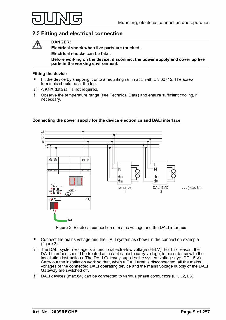
Figure 8: Controls and indicators for manual control
(7) Button cActivation / deactivation of manual control.
(8) LED c:LED ON indicates permanent manual control.
(9) Button ON/ n:Brief press: Group/single device ON / Sustained press: Increase brightness of group/singledevice.
(10) Status LED ON/ n:LED ON in manual operation indicates a switched-on group/single device(brightness: 1...100 %).
Page 14 of 257
Mounting, electrical connection and operation

Art. No. 2099REGHE
(11) Button OFF/ o:Brief press: Group/single device OFF / Sustained press: Decrease brightness ofgroup/single device.
(12) Status LED OFF/ o:LED ON in manual operation indicates a switched-off group/single device (brightness: 0%).
(13) Button ALL OFF:All DALI subscribers OFF (only in permanent manual operation).
(14) 7-segment display to show the number of a DALI group (14a) or a single device (14b)selected by manual operation. Disabled in bus operation. In addition, to display additionalinformation:
- -: Signals DALI commissioning phase or delay after an ETS programming operation ormains voltage return.
bc: Display during manual operation in an unprogrammed status (broadcast operation).
Er: Displaying an impermissible external voltage on the DALI device connection terminals(e.g. mains voltage connected). DALI Gateway without function. The Gateway is only readyfor operation again when the error has been eliminated and initialisation has beenperformed again (mains voltage return).
LE: Signals automatic device replacement.
E: Signals an error during automatic device replacement.
PrioritiesThe DALI Gateway distinguishes between different functions that can have an effect on a DALIGroup. In order to prevent conflicting output states, each available function has a certain priority.The function with the higher priority overrides the one with the lower priority.- 1st priority: manual control (highest priority)- 2nd priority: Emergency operation- 3rd priority: Forced position function or disabling function- 4th priority: Direct bus operation ("switching" & "dimming" & "brightness" & "colour
temperature" objects, scenes, effects, central function)i The priority of the scene and effect function over the disabling or forced position functions
of a group or a single device can be configured. Thus, it is possible for a scene recall or thestart of an effect to override a disabling or forced position function. Alternatively, a scene oran effect can have a lower priority, meaning that disabling functions or forced positionscannot be overridden by a scene recall or the start of an effect.
Switch on brief broadcast manual operation The broadcast manual operation can be used in the unprogrammed state of the DALI Gateway.As, in this case, missing ETS programming means that no group/individual configurations arestored in the device, the DALI Gateway, in manual operation, controls the connected DALIoperating devices jointly via a broadcast command.The DALI Gateway has not yet been programmed by the ETS.o Press the c button briefly (< 1 second).
bc is displayed in the 7-segment display.i After 5 seconds without a button being pressed, the Gateway deactivates broadcast
handling.
Page 15 of 257
Mounting, electrical connection and operation

Art. No. 2099REGHE
i Broadcast operation is preset in the delivery state. It can also be reactivated at any timeafter a programming operation by the ETS by unloading the application program using theETS.
Switch off brief broadcast manual operationThe DALI Gateway has not yet been programmed by the ETS.Temporary broadcast manual operation was activated.o No button-press for 5 seconds
- or -o Press c button.
- or -o Switch off the mains voltage supply.
Temporary broadcast manual operation is terminated. The 7-segment display goes out.i The state set via manual operation is not changed when broadcast manual operation is
switched off.
Switching on permanent broadcast manual operationThe DALI Gateway has not yet been programmed by the ETS.No broadcast manual operation or temporary broadcast manual operation is activated.o Press the c button for at least 5 seconds.
The status LED c is illuminated. bc is displayed in the 7-segment display. Permanentbroadcast manual operation is active.
Switching off permanent broadcast manual operationPermanent broadcast manual operation was active.o Press c button for at least 5 seconds.
- or -o Switch off the mains voltage supply.
Permanent broadcast manual operation is terminated. The Status LED c and the7-segment display goes out.
i The state set via manual operation is not changed when permanent broadcast manualoperation is switched off.
Operating DALI operating devices in broadcast manual operationThe DALI Gateway has not yet been programmed by the ETS.Broadcast manual operation (permanent or temporary) is activated.o Operate the operating devices by pressing the ON/n button or the OFF/o button.
Brief: Joint switch-on/switch-off.Long: Joint dim brighter/darker.Long and release: Joint dimming stop.All the connected DALI operating devices execute the corresponding commandsimmediately.
Page 16 of 257
Mounting, electrical connection and operation

Art. No. 2099REGHE
Switching off all the operating devices in broadcast manual operationPermanent broadcast manual operation is active.o Press the ALL OFF button.
All the connected DALI operating devices are shut off immediately (Brightness: 0 %). Theoperating devices are not locked. Joint activation is possible again after shutoff.
i The ALL OFF function is not available in temporary broadcast manual operation.
Switching on the temporary manual controlAfter the DALI Gateway has been programmed at least one by the ETS, at least one DALIgroup or at least one DALI single device is created and configured in the device. In this case,the created groups and single devices can be controlled individually through manual operation.Broadcast operation is then deactivated.The DALI Gateway was programmed at least once before by the ETS.Manual control is enabled in the ETS.o Press the c button briefly (< 1 second).
In the 7-segment display, the group number 01 or the single device short address 01. isdisplayed.
i After 5 seconds without a button-press, the Gateway returns automatically to busoperation.
i Broadcast operation is preset in the delivery state. It can also be reactivated at any timeafter a programming operation by the ETS by unloading the application program using theETS.
Switching off temporary manual operationTemporary manual control was activated.o No button-press for 5 seconds
- or -o Select all the groups and single devices one after another by a brief press of the c button.
Thereafter, press the c button again,- or -
o Switch the mains power supply off or reset the bus (bas voltage return).Temporary manual control is terminated. The 7-segment display goes out.
i The state set via manual control is not changed when temporary manual control is switchedoff. If, however, a forced position or disabling function has been activated via the busbefore or during manual operation, the DALI Gateway executes the disabling or forcedreactions for the groups and single devices concerned.
Switching on permanent manual controlThe DALI Gateway was programmed at least once before by the ETS.Manual control is enabled in the ETS. Bus operation or temporary manual control is active.o Press c button for at least 5 seconds.
The status LED c is illuminated. In the 7-segment display, the group number 01 or thesingle device short address 01. is displayed. Permanent manual control is active:
Page 17 of 257
Mounting, electrical connection and operation

Art. No. 2099REGHE
Switching off permanent manual controlPermanent manual control is active.o Press c button for at least 5 seconds.
- or -o Switch the mains power supply off or reset the bus (bas voltage return).
Permanent manual operation is terminated. The Status LED and the 7-segment displaygoes out.
i Depending on the configuration of the Gateway in the ETS, the groups and single deviceswill be set to the state last adjusted in the manual mode or to the brightness value internallytracked (direct operation, forced position / disabling function) when the permanent manualmode is shut off.
Operating DALI groups or single devices in manual modeThe DALI Gateway was programmed at least once before by the ETS.Manual control (permanent or temporary) is activated.o Select the desired group: Press thec button briefly (if necessary, repeatedly).
The 7-segment display shows the number of the selected DALI group or the number of theselected single device. The Status LEDs ON/n1...100 %) or OFF/o (0 %) in the buttonfield show the switching state.
o Operate the group or single device by pressing the ON/n button or OFF/o button.Short: switch on/off.Long: dim brighter/darker.Long and release: Stop dimming.The selected DALI group or the single device executes the corresponding commandsimmediately.
Switch off all groups and single devicesPermanent manual control is active:o Press the ALL OFF button.
All groups and single devices are shut off immediately (Brightness: 0 %). The groups andsingle devices are not locked. Individual activation is possible again after shutoff.
i The ALL OFF function is not available in temporary manual operation.
Disabling bus control of individual groups and devices through manual operationThe DALI Gateway was programmed at least once before by the ETS.Permanent manual control is active:Disabling of the bus control mode must have been enabled in the ETS.o Select the group or single device: Press the c button briefly (if necessary, repeatedly).
The 7-segment display shows the number of the selected DALI group or the number of theselected single device. The Status LEDs ON/n1...100 %) or OFF/o (0 %) in the buttonfield show the switching state.
o Press the ON/n and the OFF/o buttons simultaneously for at least 5 seconds.The appropriate group or single device is disabled (no bus operation is possible).The 7-segment display flashes.
i To unlock, proceed in the same way.
Page 18 of 257
Mounting, electrical connection and operation
Art. No. 2099REGHE
i A group or single device that has been disabled in manual operation can thereafter only beoperated in permanent manual operation.
Performing a DALI device replacement After starting the automatic device replacement, the DALI Gateway is able to check thecompleteness of the previously operated DALI operating devices. If, for example, a defectiveDALI electronic ballast was removed by an installation engineer and replaced by a new one, theDALI Gateway is able to program the new electronic ballast with the programming data of thefailed electronic ballast. This offers the option of replacing a failed DALI operating devicethrough simple operation on the device and without configuration work in the ETS.i When using the automatic device replacement, only operating devices of the same DALI
type can be interchanged! If operating devices of another type are to be replaced, acomplete DALI commissioning must be carried out using the ETS plug-in.
The DALI Gateway was programmed at least once before by the ETS.Automatic device replacement must be enabled in the ETS.Ensure that the bus and mains voltage (also to all DALI operating devices) is switched on.It is important that the DALI system has been fully commissioned with DALI commissioning.Only one DALI operating device may fail and be replaced.The device must be in bus operation (no manual operation active).o Press the c and the ALL OFF button simultaneously for approx. 10 seconds.
Automatic device replacement is activated. The length of the operation is dependent on thenumber of DALI operating devices in the system. During device replacement, the7-segment display signals LE (Learn). The display goes out after a successful replacementoperation.
i During device replacement, all the other functions of the DALI Gateway are stopped.During device replacement, the Gateway tracks all the received bus states and evaluatesthe most recently tracked values (switching, dimming, brightness value, scenes, effects,central function, forced position function, disabling function) normally at the end ofautomatic device replacement. An active forced position or disabling function is interruptedby device replacement and reactivated at the end of the replacement operation, if thefunctions have not been deactivated via the bus in the interim. The behaviour as at thebeginning of the forced position or disabling function is not executed again.
i Ensure that only one DALI operating device is replaced in the manner described. If multipleelectronic ballasts fail (possibly no mains voltage is switched on) and have been replaced,then the electronic ballasts cannot be identified clearly by the Gateway and not configuredautomatically. In this case, new DALI commissioning by the ETS plug-in is required.
i If an error has occurred during device replacement, the 7-segment display signals E (Error)for 3 seconds. Perform the operation again, taking the above conditions and informationinto account. This signalling also takes place if automatic device replacement wasactivated, without having replaced a DALI operating device previously.
Page 19 of 257
Mounting, electrical connection and operation

Art. No. 2099REGHE
3 Technical data
GeneralTest mark KNX/EIBAmbient temperature -5 ... +45 °CStorage/transport temperature -25 ... +70 °CFitting width 72 mm / 4 modules
SupplyRated voltage AC 110 ... 240 V ~Mains frequency 50 / 60 HzRated voltage DC 110 ... 240 VPower consumption max. 6 WPower loss max. 3 W
DALIRated voltage DALI DC 16 V (typ.)Current typ. 128 mA, max. 200 mA for short periodsNumber of DALI subscribers max. 64DALI transmission rate 1.2 kbit/sDALI protocol EN 62386Cable type Sheathed cable 230 V, e,g. NYMResistivity max. 8 ΩResistivity (simple length) max. 4 ΩDALI cable lengths...with Ø 1.5 mm² max. 300 mwith Ø 1.0 mm² max. 238 mwith Ø 0.75 mm² max. 174 mwith Ø 0.5 mm² max. 116 m
Connection of power supply and DALIConnection mode Screw terminalsingle stranded 0.5 ... 4 mm²Finely stranded without conductor sleeve 0.5 ... 4 mm²Finely stranded with conductor sleeve 0.5 ... 2.5 mm²
KNXKNX medium TP 256Commissioning mode S-modeRated voltage KNX DC 21 ... 32 V SELVCurrent consumption KNX 4.5 ... 5.0 mA
Page 20 of 257
Technical data
Art. No. 2099REGHE
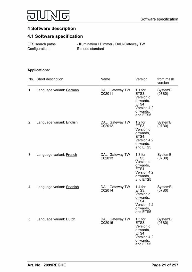
4 Software description4.1 Software specificationETS search paths: - Illumination / Dimmer / DALI-Gateway TWConfiguration: S-mode standard
Applications:
No. Short description Name Version from maskversion
1 Language variant: German DALI Gateway TWC02011
1.1 forETS3,Version donwards,ETS4Version 4.2onwards,and ETS5
SystemB(07B0)
2 Language variant: English DALI Gateway TWC02012
1.2 forETS3,Version donwards,ETS4Version 4.2onwards,and ETS5
SystemB(07B0)
3 Language variant: French DALI Gateway TWC02013
1.3 forETS3,Version donwards,ETS4Version 4.2onwards,and ETS5
SystemB(07B0)
4 Language variant: Spanish DALI Gateway TWC02014
1.4 forETS3,Version donwards,ETS4Version 4.2onwards,and ETS5
SystemB(07B0)
5 Language variant: Dutch DALI Gateway TWC02015
1.5 forETS3,Version donwards,ETS4Version 4.2onwards,and ETS5
SystemB(07B0)
Page 21 of 257
Software specification
Art. No. 2099REGHE
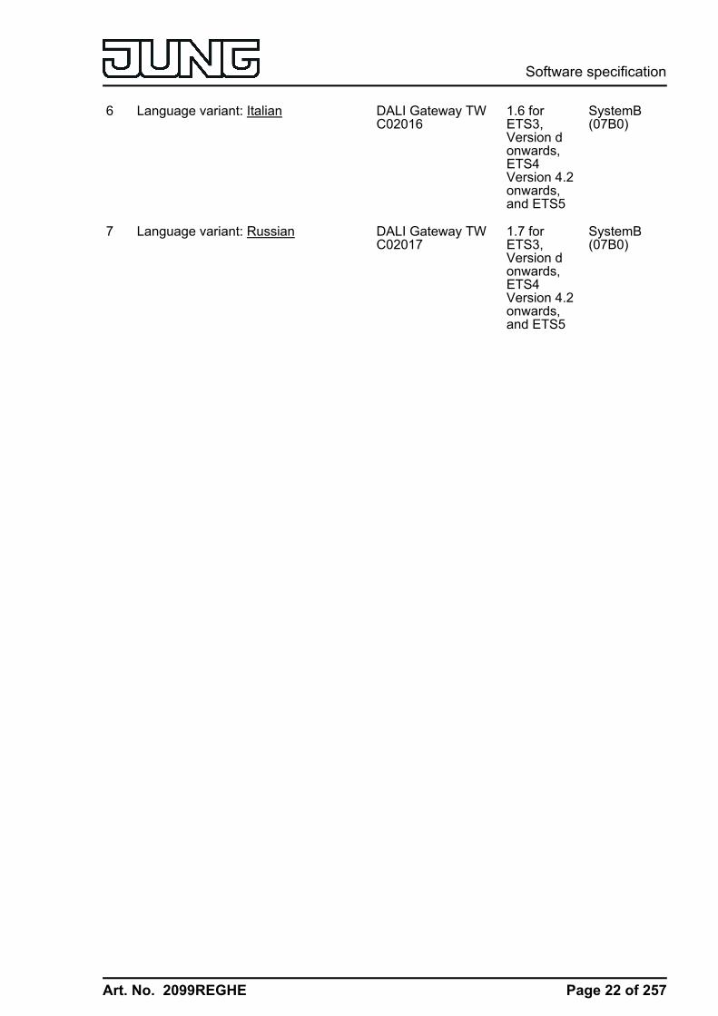
6 Language variant: Italian DALI Gateway TWC02016
1.6 forETS3,Version donwards,ETS4Version 4.2onwards,and ETS5
SystemB(07B0)
7 Language variant: Russian DALI Gateway TWC02017
1.7 forETS3,Version donwards,ETS4Version 4.2onwards,and ETS5
SystemB(07B0)
Page 22 of 257
Software specification

Art. No. 2099REGHE
4.2 Software "DALI Gateway C0201x"4.2.1 Scope of functionsGeneral:- Switching and dimming of a maximum of 64 lights with a DALI operating device (e.g.
electronic ballast).- Up to 6 different addressing types allow group-orientated and individually-address control
of DALI lights via KNX telegrams.- Up to 32 independent DALI groups are available for group addressing. For alternative
control, these can be supplemented with 64 individually-addressable DALI devicechannels, as necessary.
- Control support of DALI operating devices of the device type "Colour Control" (DALI DeviceType 8) in the specific version "Tunable White (TW)". Colour temperature control viarelative or absolute dimming as well as via scenes and effects. The colour temperaturecontrol is largely independent of the brightness control and luminaire used.
- Optional master control of all connected DALI components is possible (broadcast). Thismeans that there is no need to commission DALI, meaning that lighting systems with fewfunctions can be started up quickly and easily (simplified configuration without DALIcommissioning).
- Manual operation of the groups and single devices independent of the bus (also buildingsite operation possible with broadcast control). Control of the switching status andbrightness.
- Feedback of DALI error status (1-byte or 2-byte according to the KNX standard) or DALIshort-circuit and message that the supply voltage has failed.
- Central switching function.- Collective feedback of all switching states possible.- Incorporation of the groups and single devices into up to 16 light scenes.- Integration of lights or light groups in the effect control for the implementation of dynamic
light scenes. Up to 16 effects are available here, each with up to 16 effect steps. A timer isavailable if necessary, which means that individual effects can be started and stoppeddepending on the time and weekday.
Group and device functions:- Each group and single device offers the full scope of functions without any restrictions. All
channel-oriented functions can be parameterised separately for each group or singledevice. This feature permits independent and multi-functional control of the DALI operatingdevices.
- Feedback of switching and brightness value: Active (transmitting after changes or cyclicallyto the bus) or passive (object readout) feedback functions.
- Setting of the brightness limit values (minimum brightness, maximum brightness) possible.- Dimming behaviour and dimming characteristics configurable.- Lamp preserving switch on and switch off (soft ON or soft OFF).- Disabling function, or alternatively, forced position function is configurable. During a
disabling function, the flashing of lights and single devices is not possible.- Timing functions (switch-on delay, switch-off delay, staircase lighting timer, also with pre-
warning function).- Operating hours counter- DALI Power ON level (using parameter "Behaviour after bus voltage return") and DALI
system failure level (using parameter "Behaviour in case of bus voltage failure) can be set.In emergency lighting operation, the DALI system failure level can also be configuredseparately.
Page 23 of 257
Software "DALI Gateway C0201x"Scope of functions
Art. No. 2099REGHE
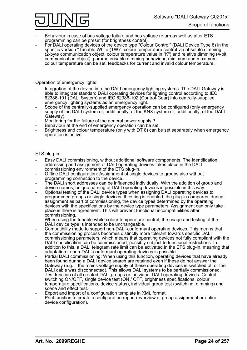
- Behaviour in case of bus voltage failure and bus voltage return as well as after ETSprogramming can be preset (for brightness control).
- For DALI operating devices of the device type "Colour Control" (DALI Device Type 8) in thespecific version "Tunable White (TW)": colour temperature control via absolute dimming(2-byte communication object, colour temperature value in "K") and relative dimming (4-bitcommunication object), parameterisable dimming behaviour, minimum and maximumcolour temperature can be set, feedbacks for current and invalid colour temperature.
Operation of emergency lights:- Integration of the device into the DALI emergency lighting systems. The DALI Gateway is
able to integrate standard DALI operating devices for lighting control according to IEC62386-101 (DALI System) and IEC 62386-102 (Control-Gear) into centrally-suppliedemergency lighting systems as an emergency light.
- Scope of the centrally-supplied emergency operation can be configured (only emergencysupply of the DALI system or, additionally, of the KNX system or, additionally, of the DALIGateway).
- Monitoring for the failure of the general power supply ?- Behaviour at the end of emergency operation can be set.- Brightness and colour temperature (only with DT 8) can be set separately when emergency
operation is active.
ETS plug-in:- Easy DALI commissioning, without additional software components. The identification,
addressing and assignment of DALI operating devices takes place in the DALIcommissioning environment of the ETS plug-in.
- Offline DALI configuration: Assignment of single devices to groups also withoutprogramming connection to the device.
- The DALI short addresses can be influenced individually. With the addition of group anddevice names, unique naming of DALI operating devices is possible in this way.
- Optional testing of the DALI device types when assigning DALI operating devices toprogrammed groups or single devices. If testing is enabled, the plug-in compares, duringassignment as part of commissioning, the device types determined by the operatingdevices with the specifications by the device type parameters. Assignment can only takeplace is there is agreement. This will prevent functional incompatibilities aftercommissioning.When using the tunable white colour temperature control, the usage and testing of theDALI device type is intended to be unchangeable.
- Compatibility mode to support non-DALI-conformant operating devices. This means thatthe commissioning process becomes distinctly more tolerant towards specific DALIcommissioning parameters, which means that operating devices not fully compliant with theDALI specification can be commissioned, possibly subject to functional restrictions. Inaddition to this, a DALI telegram rate limit can be activated in the ETS plug-in, meaning thatadaptation to non-DALI-conformant operating devices is possible.
- Partial DALI commissioning: When using this function, operating devices that have alreadybeen found during a DALI device search are retained even if these do not answer theGateway (e.g. if the mains voltage supply of these operating devices is switched off or theDALI cable was disconnected). This allows DALI systems to be partially commissioned.
- Test function of all created DALI groups or individual DALI operating devices: Centralswitching ON/OFF, single device test (ON / OFF, brightness specifications, colourtemperature specifications, device status), individual group test (switching, dimming) andscene and effect test.
- Export and import of a configuration template in XML format.- Print function to create a configuration report (overview of group assignment or entire
device configuration).
Page 24 of 257
Software "DALI Gateway C0201x"Scope of functions

Art. No. 2099REGHE
4.2.2 Notes on software
ETS project design and commissioningFor project design and commissioning of this device, we recommend using the ETS5. Projectdesigning and commissioning of the device using ETS4 (from version 4.2) ETS3 from version"d" is also possible. Additional hardware or software is not required for the configuration andcommissioning of the DALI Gateway.Each language variant has its own version of the application program (for example: Version 1.1.= German, 1.2 = English).
Safe-state modeIf the device - for instance as a result of errors in the project design or during commissioning -does not work properly, the execution of the loaded application program can be halted byactivating the safe-state mode. The safe-state mode does not permit control of the DALIoperating devices via the KNX. Only broadcast manual operation can be activated. TheGateway remains passive in safe-state mode, since the application program is not beingexecuted (state-of-execution: terminated). Only the system software is still functional so that theETS diagnosis functions and also programming of the device continue to be possible.
Activating the safe-state modeo Switch off the mains voltage supply.o Wait about one minute.o Press and hold down the programming button.o Switch on the mains supply. Release the programming button only after the programming
LED starts flashing slowly.The safe-state mode is activated.
i The safe-state mode can be terminated by switching off the mains voltage supply (again,wait approx. one minute) or by programming with the ETS.
i The bus voltage does not have to be switched on to activate safe-state mode.i Even in safe-state mode, a brief press of the programming button can switch the
programming mode on and off as usual. The programming LED then stops flashing, eventhough safe-state mode is still active. Safe-state mode must also first be exited, in order torestore normal operation of the DALI Gateway.
Unloading the application programThe application program can be unloaded with the ETS. In this case, only broadcast manualoperation of the connected DALI operating devices is possible.
Page 25 of 257
Software "DALI Gateway C0201x"Notes on software
Art. No. 2099REGHE
4.2.3 Object table
4.2.3.1 Objects for group and single devices
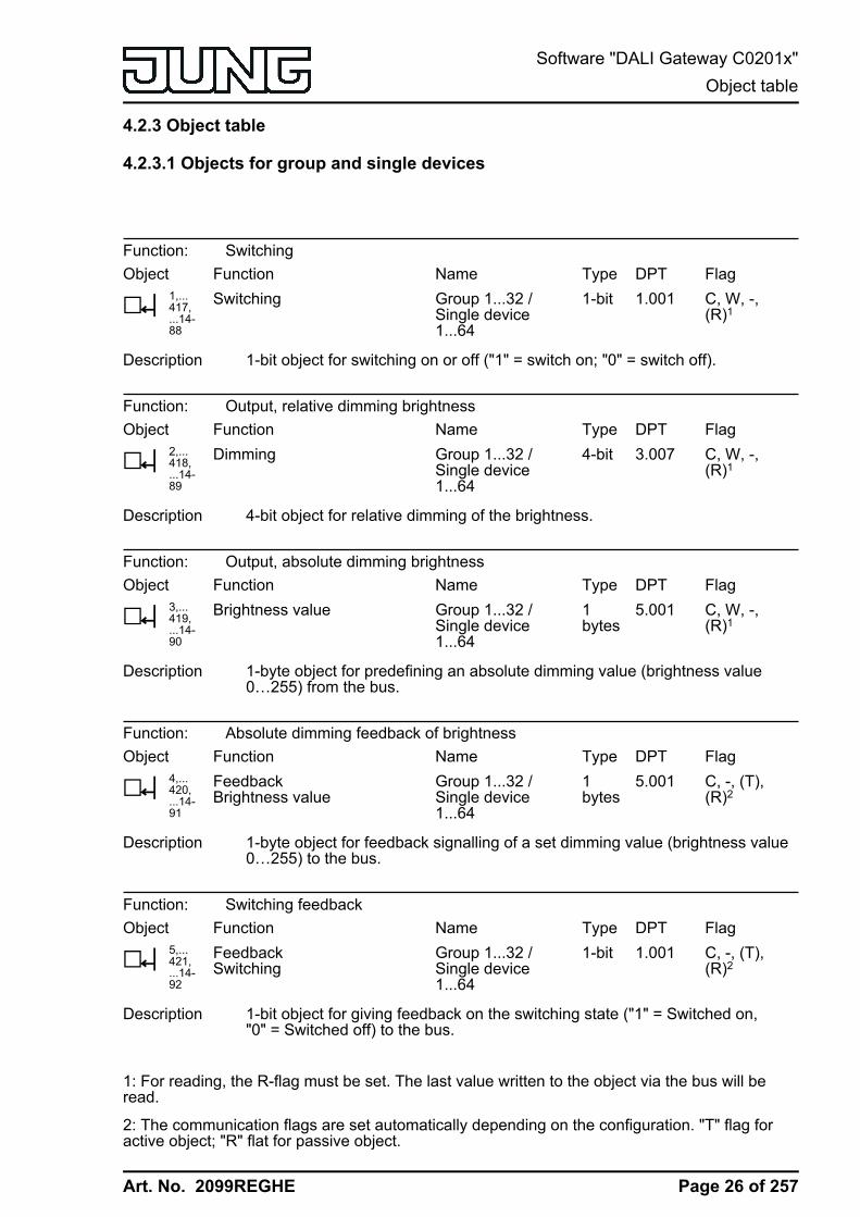
Function: SwitchingObject
h1,...417,...14-88
FunctionSwitching
NameGroup 1...32 /Single device1...64
Type1-bit
DPT1.001
FlagC, W, -,(R)1
Description 1-bit object for switching on or off ("1" = switch on; "0" = switch off).
Function: Output, relative dimming brightnessObject
h2,...418,...14-89
FunctionDimming
NameGroup 1...32 /Single device1...64
Type4-bit
DPT3.007
FlagC, W, -,(R)1
Description 4-bit object for relative dimming of the brightness.
Function: Output, absolute dimming brightnessObject
h3,...419,...14-90
FunctionBrightness value
NameGroup 1...32 /Single device1...64
Type1bytes
DPT5.001
FlagC, W, -,(R)1
Description 1-byte object for predefining an absolute dimming value (brightness value0…255) from the bus.
Function: Absolute dimming feedback of brightnessObject
h4,...420,...14-91
FunctionFeedbackBrightness value
NameGroup 1...32 /Single device1...64
Type1bytes
DPT5.001
FlagC, -, (T),(R)2
Description 1-byte object for feedback signalling of a set dimming value (brightness value0…255) to the bus.
Function: Switching feedbackObject
h5,...421,...14-92
FunctionFeedbackSwitching
NameGroup 1...32 /Single device1...64
Type1-bit
DPT1.001
FlagC, -, (T),(R)2
Description 1-bit object for giving feedback on the switching state ("1" = Switched on,"0" = Switched off) to the bus.
1: For reading, the R-flag must be set. The last value written to the object via the bus will beread.
2: The communication flags are set automatically depending on the configuration. "T" flag foractive object; "R" flat for passive object.
Page 26 of 257
Software "DALI Gateway C0201x"Object table

Art. No. 2099REGHE
Function: Staircase functionObject
h6,...422,...14-93
FunctionStaircase functionstart / stop
NameGroup 1...32 /Single device1...64
Type1-bit
DPT1.010
FlagC, W, -,(R)1
Description 1-bit object to activate or deactivate the switch-on time of the staircasefunction ("1" = switch-on / "0" = switch-off).
Function: Staircase functionObject
h7,...423,...14-94
FunctionStaircase timeFactor
NameGroup 1...32 /Single device1...64
Type1bytes
DPT5.010
FlagC, W, -,(R)1
Description 1-byte object to specify a time factor for the switch-on time of the staircasefunction (value range: 0...255).
Function: Operating hours counterObject
h8,...424,...14-95
FunctionOHC start/limiting value 2
NameGroup 1...32 /Single device1...64
Type2bytes
DPT7.007
FlagC, W, -,(R)1
Description 2-byte object for external specification of a limit value / starting value of theoperating hours counter (value range: 0...65535).
Function: Operating hours counterObject
h9,...425,...14-96
FunctionOHC restart
NameGroup 1...32 /Single device1...64
Type1-bit
DPT1.015
FlagC, W, -,(R)1
Description 1-bit object for resetting the operating hours counter ("1" = restart, "0" = noreaction).
Function: Operating hours counterObject
h10,...426,...14-97
FunctionOHC value
NameGroup 1...32 /Single device1...64
Type2bytes
DPT7.007
FlagC, -, T, (R)3
Description 2-byte object to transmit or read out the current counter level of the operatinghours counter.If the bus voltage should fail, the value of the communication object is not lostand is actively transmitted to the bus after bus voltage return or an ETSprogramming operation. In the as-delivered state, the value is "0".
1: For reading, the R-flag must be set. The last value written to the object via the bus will beread.
2: Threshold value object or start value object depending on the configured counter type of theoperating hours counter.
3: For reading, the R-flag must be set. The last value written to the object via the bus or by thedevice will be read.
Page 27 of 257
Software "DALI Gateway C0201x"Object table
Art. No. 2099REGHE
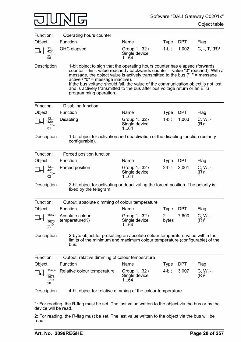
Function: Operating hours counterObject
h11,...427,...14-98
FunctionOHC elapsed
NameGroup 1...32 /Single device1...64
Type1-bit
DPT1.002
FlagC, -, T, (R)1
Description 1-bit object to sign that the operating hours counter has elapsed (forwardscounter = limit value reached / backwards counter = value "0" reached). With amessage, the object value is actively transmitted to the bus ("1" = messageactive / "0" = message inactive).If the bus voltage should fail, the value of the communication object is not lostand is actively transmitted to the bus after bus voltage return or an ETSprogramming operation.
Function: Disabling functionObject
h12,...430,...15-01
FunctionDisabling
NameGroup 1...32 /Single device1...64
Type1-bit
DPT1.003
FlagC, W, -,(R)2
Description 1-bit object for activation and deactivation of the disabling function (polarityconfigurable).
Function: Forced position function Object
h13,...431,...15-02
FunctionForced position
NameGroup 1...32 /Single device1...64
Type2-bit
DPT2.001
FlagC, W, -,(R)2
Description 2-bit object for activating or deactivating the forced position. The polarity isfixed by the telegram.
Function: Output, absolute dimming of colour temperatureObject
h1547-,...1675,...19-27
FunctionAbsolute colourtemperature(K)
NameGroup 1...32 /Single device1...64
Type2bytes
DPT7.600
FlagC, W, -,(R)2
Description 2-byte object for presetting an absolute colour temperature value within thelimits of the minimum and maximum colour temperature (configurable) of thebus.
Function: Output, relative dimming of colour temperatureObject
h1548-,...1676,...19-28
FunctionRelative colour temperature
NameGroup 1...32 /Single device1...64
Type4-bit
DPT3.007
FlagC, W, -,(R)2
Description 4-bit object for relative dimming of the colour temperature.
1: For reading, the R-flag must be set. The last value written to the object via the bus or by thedevice will be read.
2: For reading, the R-flag must be set. The last value written to the object via the bus will beread.
Page 28 of 257
Software "DALI Gateway C0201x"Object table

Art. No. 2099REGHE
Function: Absolute dimming feedback of colour temperatureObject
h1549-,...1677,...19-29
FunctionFB absolute colourtemper.(K)
NameGroup 1...32 /Single device1...64
Type2bytes
DPT7.600
FlagC, -, (T),(R)1
Description 2-byte object for feedback signalling of a set colour temperature to the bus.
Function: Absolute dimming feedback of colour temperatureObject
h1550-,...1678,...19-30
FunctionRM invalid colour temp.
NameGroup 1...32 /Single device1...64
Type1-bit
DPT1.001
FlagC, -, (T),(R)1
Description 1-bit object for feedback signalling of an invalidly set colour temperature ("1" =colour temperature invalid, "0" = colour temperature valid) via the object"Absolute colour temperature (K)". A colour temperature set externally isinvalid if this violates the set limits of the minimum and maximum colourtemperature.After a device reset (ETS programming operation, mains voltage return), thestatus "valid colour temperature" is always transmitted if an object is activelytransmitting.
1: The communication flags are set automatically depending on the configuration. "T" flag foractive object; "R" flat for passive object.
Page 29 of 257
Software "DALI Gateway C0201x"Object table

Art. No. 2099REGHE
4.2.3.2 Objects for scenes and effects
Function: Scene functionObject
h1505
FunctionExtension input
NameScenes
Type1bytes
DPT18.001
FlagC, W, -,(R)1
Description 1-byte object for recalling scenes (Bit 7 deleted) or for storing new scenevalues (Bit 7 set). Bits 0...6 carry the configurable KNX scene number (0...63 -> KNX scene number 1...64).
Function: Effect controlObject
h1507-...15-22
FunctionStart / Stop
NameEffect 1...16
Type1-bit
DPT1.010
FlagC, W, -,(R)1
Description 1-bit object to start and stop individual effects ("1" = Start effect, "0" = Stopeffect). Effects can run simultaneously and also influence each other, providedthat the same groups, single devices or scenes are integrated in the effectsteps.
Function: Effect controlObject
h1523
FunctionExtension input
NameEffects
Type1bytes
DPT18.001
FlagC, W, -,(R)1
Description 1-bit object to start (Bit 7 deleted) and stop (Bit 7 set) individual effects. Bits0...6 carry the configurable KNX effect number (0...63 -> KNX effect number1...64).
Function: Effect controlObject
h1545
FunctionTime
NameEffects
Type3bytes
DPT10.001
FlagC, W, -,(R)1
Description 3-byte object for providing the current time and current weekday for the timerfunction of the effect control.If no valid weekday is transmitted in the telegram, the timer executes theconfigured times for starting and stopping individual effects daily.This object is only available with the configured "3-byte" time data format!
1: For reading, the R-flag must be set. The last value written to the object via the bus will beread.
Page 30 of 257
Software "DALI Gateway C0201x"Object table
Art. No. 2099REGHE
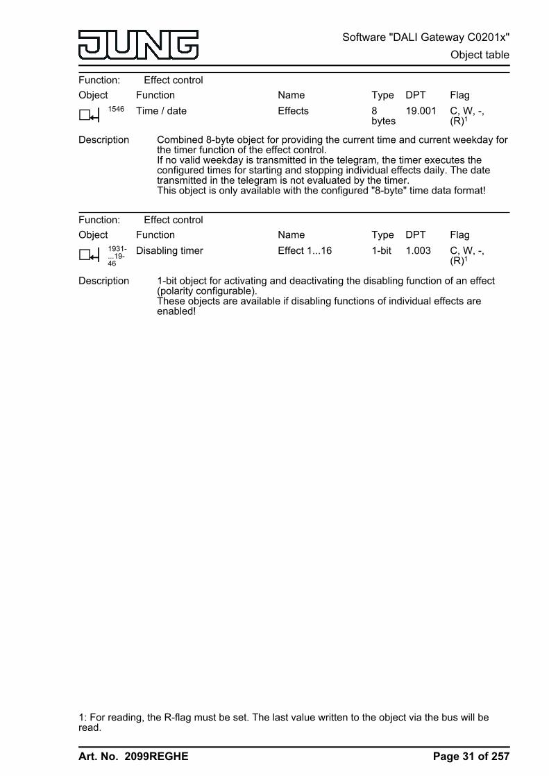
Function: Effect controlObject
h1546
FunctionTime / date
NameEffects
Type8bytes
DPT19.001
FlagC, W, -,(R)1
Description Combined 8-byte object for providing the current time and current weekday forthe timer function of the effect control.If no valid weekday is transmitted in the telegram, the timer executes theconfigured times for starting and stopping individual effects daily. The datetransmitted in the telegram is not evaluated by the timer.This object is only available with the configured "8-byte" time data format!
Function: Effect controlObject
h1931-...19-46
FunctionDisabling timer
NameEffect 1...16
Type1-bit
DPT1.003
FlagC, W, -,(R)1
Description 1-bit object for activating and deactivating the disabling function of an effect(polarity configurable).These objects are available if disabling functions of individual effects areenabled!
1: For reading, the R-flag must be set. The last value written to the object via the bus will beread.
Page 31 of 257
Software "DALI Gateway C0201x"Object table

Art. No. 2099REGHE
4.2.3.3 Object for emergency lighting
Function: Emergency lightingObject
h1538
FunctionFailure of external supply
NameEmergencylighting
Type1-bit
DPT1.002
FlagC, W, -, (R) 1
Description Using this 1-bit object, a different KNX bus device (e.g. binary input) caninform the DALI Gateway that the general mains voltage supply has failed.With this, the Gateway then activates emergency operation."1" = Mains voltage has failed, "0" = Mains voltage available.To allow telegram transmission and evaluation, the KNX system and themains voltage supply of the DALI Gateway must be integrated in the centralemergency power supply.
Function: Emergency lightingObject
h1539
FunctionFeedback Failure of supply
NameEmergencylighting
Type1-bit
DPT1.002
FlagC, -, T, (R)2
Description Using this 1-bit object, the DALI Gateway can inform other bus devices thatthe general mains voltage supply has failed. According to the configuration,the Gateway obtains the information for this from the object "Failure, externalsupply" and/or from the internal failure message of the DALI system. Otherbus devices evaluating this feedback (e.g. other KNX DALI Gateways) canthen respond appropriately and also activate emergency operation."1" = Mains voltage has failed, "0" = Mains voltage available.To allow telegram transmission and evaluation, the KNX system and themains power supplies of the DALI Gateway must be integrated in the centralemergency power supply.
Function: Emergency lightingObject
h1540
FunctionEmergency operation externmsg
NameEmergencylighting
Type1-bit
DPT1.003
FlagC, W, -, (R)1
Description Using this 1-bit object, a different KNX bus device (e.g. another DALI Gateway-> link to the object "Feedback, supply failure") can inform the DALI Gatewaythat emergency operation has been activated. Through this, the Gateway thenactivates emergency operation, without having to identify the failure of thegeneral mains voltage supply itself."1" = Mains voltage has failed / Activate emergency operation, "0" = Mainsvoltage available / Deactivate emergency operation.To allow telegram transmission and evaluation, the KNX system and themains voltage supply of the DALI Gateway must be integrated in the centralemergency power supply.
1: For reading, the R-flag must be set. The last value written to the object via the bus will beread.
2: For reading, the R-flag must be set. The last value written to the object via the bus or by thedevice will be read.
Page 32 of 257
Software "DALI Gateway C0201x"Object table
Art. No. 2099REGHE
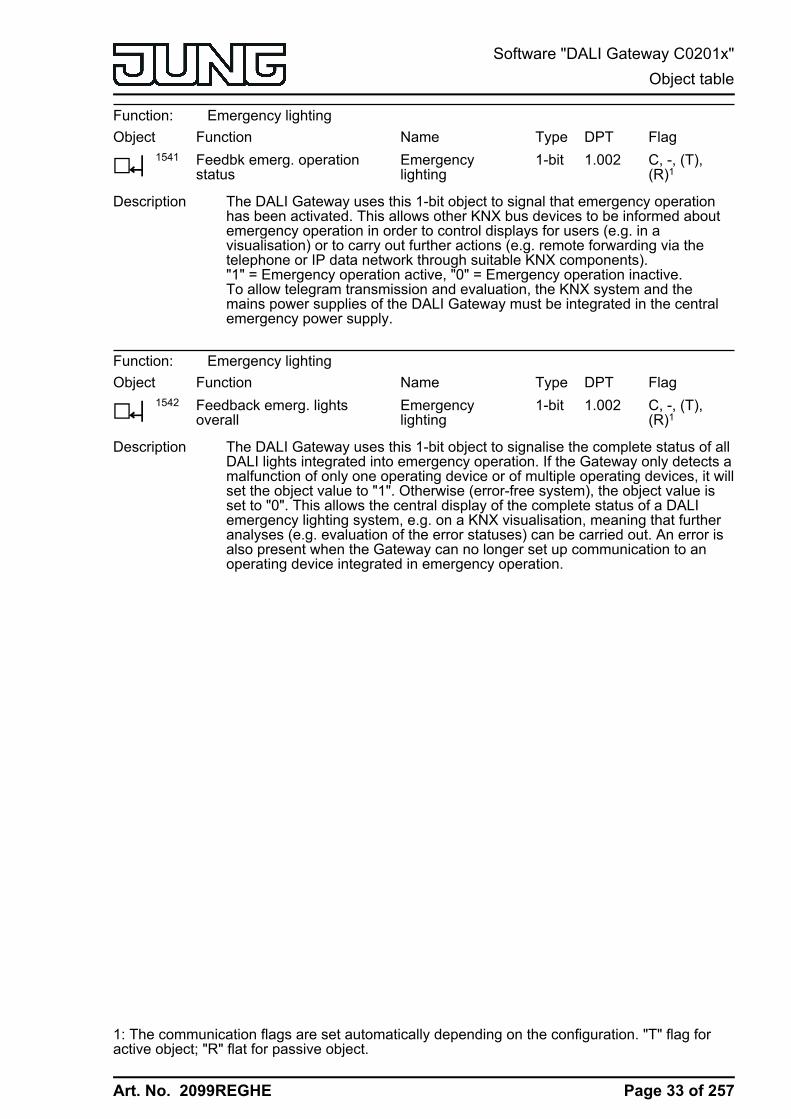
Function: Emergency lightingObject
h1541
FunctionFeedbk emerg. operationstatus
NameEmergencylighting
Type1-bit
DPT1.002
FlagC, -, (T),(R)1
Description The DALI Gateway uses this 1-bit object to signal that emergency operationhas been activated. This allows other KNX bus devices to be informed aboutemergency operation in order to control displays for users (e.g. in avisualisation) or to carry out further actions (e.g. remote forwarding via thetelephone or IP data network through suitable KNX components)."1" = Emergency operation active, "0" = Emergency operation inactive.To allow telegram transmission and evaluation, the KNX system and themains power supplies of the DALI Gateway must be integrated in the centralemergency power supply.
Function: Emergency lightingObject
h1542
FunctionFeedback emerg. lightsoverall
NameEmergencylighting
Type1-bit
DPT1.002
FlagC, -, (T),(R)1
Description The DALI Gateway uses this 1-bit object to signalise the complete status of allDALI lights integrated into emergency operation. If the Gateway only detects amalfunction of only one operating device or of multiple operating devices, it willset the object value to "1". Otherwise (error-free system), the object value isset to "0". This allows the central display of the complete status of a DALIemergency lighting system, e.g. on a KNX visualisation, meaning that furtheranalyses (e.g. evaluation of the error statuses) can be carried out. An error isalso present when the Gateway can no longer set up communication to anoperating device integrated in emergency operation.
1: The communication flags are set automatically depending on the configuration. "T" flag foractive object; "R" flat for passive object.
Page 33 of 257
Software "DALI Gateway C0201x"Object table
Art. No. 2099REGHE
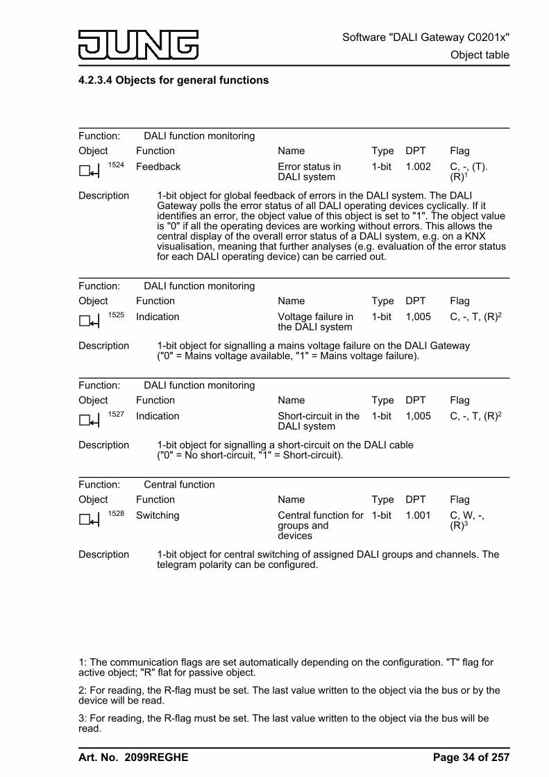
4.2.3.4 Objects for general functions
Function: DALI function monitoringObject
h1524
FunctionFeedback
NameError status inDALI system
Type1-bit
DPT1.002
FlagC, -, (T).(R)1
Description 1-bit object for global feedback of errors in the DALI system. The DALIGateway polls the error status of all DALI operating devices cyclically. If itidentifies an error, the object value of this object is set to "1". The object valueis "0" if all the operating devices are working without errors. This allows thecentral display of the overall error status of a DALI system, e.g. on a KNXvisualisation, meaning that further analyses (e.g. evaluation of the error statusfor each DALI operating device) can be carried out.
Function: DALI function monitoringObject
h1525
FunctionIndication
NameVoltage failure inthe DALI system
Type1-bit
DPT1,005
FlagC, -, T, (R)2
Description 1-bit object for signalling a mains voltage failure on the DALI Gateway("0" = Mains voltage available, "1" = Mains voltage failure).
Function: DALI function monitoringObject
h1527
FunctionIndication
NameShort-circuit in theDALI system
Type1-bit
DPT1,005
FlagC, -, T, (R)2
Description 1-bit object for signalling a short-circuit on the DALI cable("0" = No short-circuit, "1" = Short-circuit).
Function: Central functionObject
h1528
FunctionSwitching
NameCentral function forgroups anddevices
Type1-bit
DPT1.001
FlagC, W, -,(R)3
Description 1-bit object for central switching of assigned DALI groups and channels. Thetelegram polarity can be configured.
1: The communication flags are set automatically depending on the configuration. "T" flag foractive object; "R" flat for passive object.
2: For reading, the R-flag must be set. The last value written to the object via the bus or by thedevice will be read.
3: For reading, the R-flag must be set. The last value written to the object via the bus will beread.
Page 34 of 257
Software "DALI Gateway C0201x"Object table
Art. No. 2099REGHE
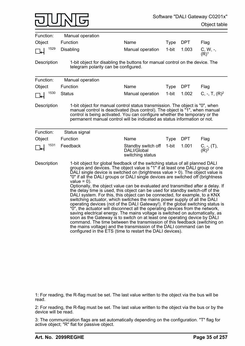
Function: Manual operationObject
h1529
FunctionDisabling
NameManual operation
Type1-bit
DPT1.003
FlagC, W, -,(R)1
Description 1-bit object for disabling the buttons for manual control on the device. Thetelegram polarity can be configured.
Function: Manual operationObject
h1530
FunctionStatus
NameManual operation
Type1-bit
DPT1.002
FlagC, -, T, (R)2
Description 1-bit object for manual control status transmission. The object is "0", whenmanual control is deactivated (bus control). The object is "1", when manualcontrol is being activated. You can configure whether the temporary or thepermanent manual control will be indicated as status information or not.
Function: Status signalObject
h1531
FunctionFeedback
NameStandby switch offDALI/Globalswitching status
Type1-bit
DPT1.001
FlagC, -, (T),(R)3
Description 1-bit object for global feedback of the switching status of all planned DALIgroups and devices. The object value is "1" if at least one DALI group or oneDALI single device is switched on (brightness value > 0). The object value is"0" if all the DALI groups or DALI single devices are switched off (brightnessvalue = 0).Optionally, the object value can be evaluated and transmitted after a delay. Ifthe delay time is used, this object can be used for standby switch-off of theDALI system. For this, this object can be connected, for example, to a KNXswitching actuator, which switches the mains power supply of all the DALIoperating devices (not of the DALI Gateway!). If the global switching status is"0", the actuator will disconnect all the operating devices from the network,saving electrical energy. The mains voltage is switched on automatically, assoon as the Gateway is to switch on at least one operating device by DALIcommand. The time between the transmission of this feedback (switching onthe mains voltage) and the transmission of the DALI command can beconfigured in the ETS (time to restart the DALI devices).
1: For reading, the R-flag must be set. The last value written to the object via the bus will beread.
2: For reading, the R-flag must be set. The last value written to the object via the bus or by thedevice will be read.
3: The communication flags are set automatically depending on the configuration. "T" flag foractive object; "R" flat for passive object.
Page 35 of 257
Software "DALI Gateway C0201x"Object table
Art. No. 2099REGHE
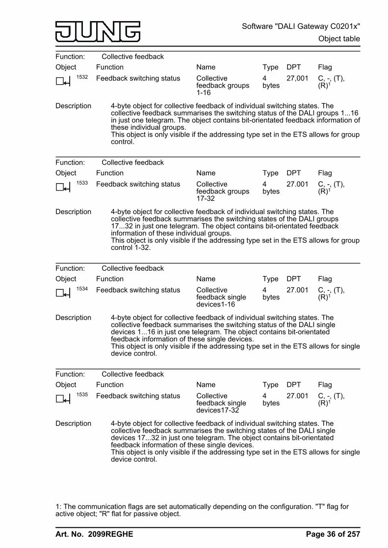
Function: Collective feedbackObject
h1532
FunctionFeedback switching status
NameCollectivefeedback groups1-16
Type4bytes
DPT27,001
FlagC, -, (T),(R)1
Description 4-byte object for collective feedback of individual switching states. Thecollective feedback summarises the switching status of the DALI groups 1...16in just one telegram. The object contains bit-orientated feedback information ofthese individual groups.This object is only visible if the addressing type set in the ETS allows for groupcontrol.
Function: Collective feedbackObject
h1533
FunctionFeedback switching status
NameCollectivefeedback groups17-32
Type4bytes
DPT27.001
FlagC, -, (T),(R)1
Description 4-byte object for collective feedback of individual switching states. Thecollective feedback summarises the switching states of the DALI groups17...32 in just one telegram. The object contains bit-orientated feedbackinformation of these individual groups.This object is only visible if the addressing type set in the ETS allows for groupcontrol 1-32.
Function: Collective feedbackObject
h1534
FunctionFeedback switching status
NameCollectivefeedback singledevices1-16
Type4bytes
DPT27.001
FlagC, -, (T),(R)1
Description 4-byte object for collective feedback of individual switching states. Thecollective feedback summarises the switching status of the DALI singledevices 1...16 in just one telegram. The object contains bit-orientatedfeedback information of these single devices.This object is only visible if the addressing type set in the ETS allows for singledevice control.
Function: Collective feedbackObject
h1535
FunctionFeedback switching status
NameCollectivefeedback singledevices17-32
Type4bytes
DPT27.001
FlagC, -, (T),(R)1
Description 4-byte object for collective feedback of individual switching states. Thecollective feedback summarises the switching states of the DALI singledevices 17...32 in just one telegram. The object contains bit-orientatedfeedback information of these single devices.This object is only visible if the addressing type set in the ETS allows for singledevice control.
1: The communication flags are set automatically depending on the configuration. "T" flag foractive object; "R" flat for passive object.
Page 36 of 257
Software "DALI Gateway C0201x"Object table

Art. No. 2099REGHE
Function: Collective feedbackObject
h1536
FunctionFeedback switching status
NameCollectivefeedback singledevices33-48
Type4bytes
DPT27.001
FlagC, -, (T),(R)1
Description 4-byte object for collective feedback of individual switching states. Thecollective feedback summarises the switching status of the DALI singledevices 33...48 in just one telegram. The object contains bit-orientatedfeedback information of these single devices.This object is only visible if the addressing type set in the ETS allows for singledevice control.
Function: Collective feedbackObject
h1537
FunctionFeedback switching status
NameCollectivefeedback singledevices49-64
Type4bytes
DPT27.001
FlagC, -, (T),(R)1
Description 4-byte object for collective feedback of individual switching states. Thecollective feedback summarises the switching status of the DALI singledevices 49...64 in just one telegram. The object contains bit-orientatedfeedback information of these single devices.This object is only visible if the addressing type set in the ETS allows for singledevice control.
Function: DALI function monitoringObject
h1543
FunctionFeedback
NameError status perDALI operatingdevice
Type1bytes
DPT238.60-0
FlagC, W, T,(R)2,3
Description 1-byte object to transmit and read out the error status of individual DALIoperating devices connected to the system. The following bit assignment isused:Bit 0...5: Number of the DALI operating device (0...63)Bit 6: Lamp error ("0" = No error, "1" = Error)Bit 7: Electronic ballast error ("0" = No error, "1" = Error)When operating as a passive status object, this object can always receivetelegrams (ValueWrite) as a transmission request. A received telegram isanswered immediately by this object (ValueWrite) by transmitting the queriederror status as an answer. In the query telegram, Bits 0...5 must contain thenumber of the electronic ballast (number of electronic ballast error status =short address - 1). Bits 6 and 7 must be set to "1". Otherwise, the querytelegram will be ignored.
1: The communication flags are set automatically depending on the configuration. "T" flag foractive object; "R" flat for passive object.
2: The communication flags are set automatically depending on the configuration. "T" flag foractive object; "S" and "T" flag for passive object.
3: For reading, the R-flag must be set. The last value written to the object via the bus or by thedevice will be read.
Page 37 of 257
Software "DALI Gateway C0201x"Object table

Art. No. 2099REGHE
Function: DALI function monitoringObject
h1544
FunctionFeedback
NameKNX error statusper DALI operatingdevice
Type2bytes
DPT237.60-0
FlagC, W, T,(R)1,2
Description 2-byte object to transmit and read out the error status of individual DALIoperating devices connected to the system, according to the KNX standard.The error states of all the devices of a DALI group can also be transferred orread out collectively. The following bit assignment is used:Bit 0...5: Number of the DALI operating device (0...63) or of the DALI group(0...15).Bit 6: Address bit ("0" = Individual operating device addressed, "1" = Groupaddressed)Bit 7: Transmission request ("0" = No transmission request / Response orspontaneous telegram, "1" = Transmission request)Bit 8: Lamp error ("0" = No error, "1" = Error)Bit 9: Electronic ballast error ("0" = No error, "1" = Error)Bit 10: Converter error ("0" = No error, "1" = Error)When operating as a passive status object, this object can always receivetelegrams (ValueWrite) as a transmission request (Bit 7 = "1"). A receivedtelegram is answered immediately by this object (ValueWrite) by transmittingthe queried error status as an answer. In the query telegram, Bits 0...5 mustcontain the number of the electronic ballast (number of electronic ballast errorstatus = short address - 1) or that of the group (number of group error status =DALI group number - 1). Bit 6 must show whether this is single deviceaddressing or group addressing. The states of Bits 8...10 in the transmissionrequest are irrelevant.
1: The communication flags are set automatically depending on the configuration. "T" flag foractive object; "S" and "T" flag for passive object.
2: For reading, the R-flag must be set. The last value written to the object via the bus or by thedevice will be read.
Page 38 of 257
Software "DALI Gateway C0201x"Object table

Art. No. 2099REGHE
4.2.4 Functional description
4.2.4.1 Application basics
4.2.4.1.1 DALI system and addressing types
DALI systemThe DALI Gateway forms the interface between a KNX building installation and a DALI (DigitalAddressable Lighting Interface) lighting system. Usually, DALI systems are room-orientated andcover high functional light management requirements, for example in offices, training orconference rooms. With these applications, it is often necessary also to integrate the room-orientated DALI system into the multi-building KNX device technology. In this way, not only thecontrol of the DALI light system using KNX sensor components becomes possible, but also theintegration of the building-side blind, heating and air conditioning systems into the lightmanagement.
Figure 9: Principle overview of a KNX-DALI system integration (example)
Within the system, the DALI Gateway functions as a master control component (mastercontroller), which also guarantees the power supply of the DALI interface. The DALI operatingdevices, e.g. DALI electronic ballasts, work as command receivers (slaves), which only returnstates or status messages to the master on request. It is the sole task of the DALI Gateway totransmit control commands received from the KNX onto the DALI cable and to check theoperating devices. The use of additional DALI control components in multimaster operation, for
Page 39 of 257
Software "DALI Gateway C0201x"Functional description
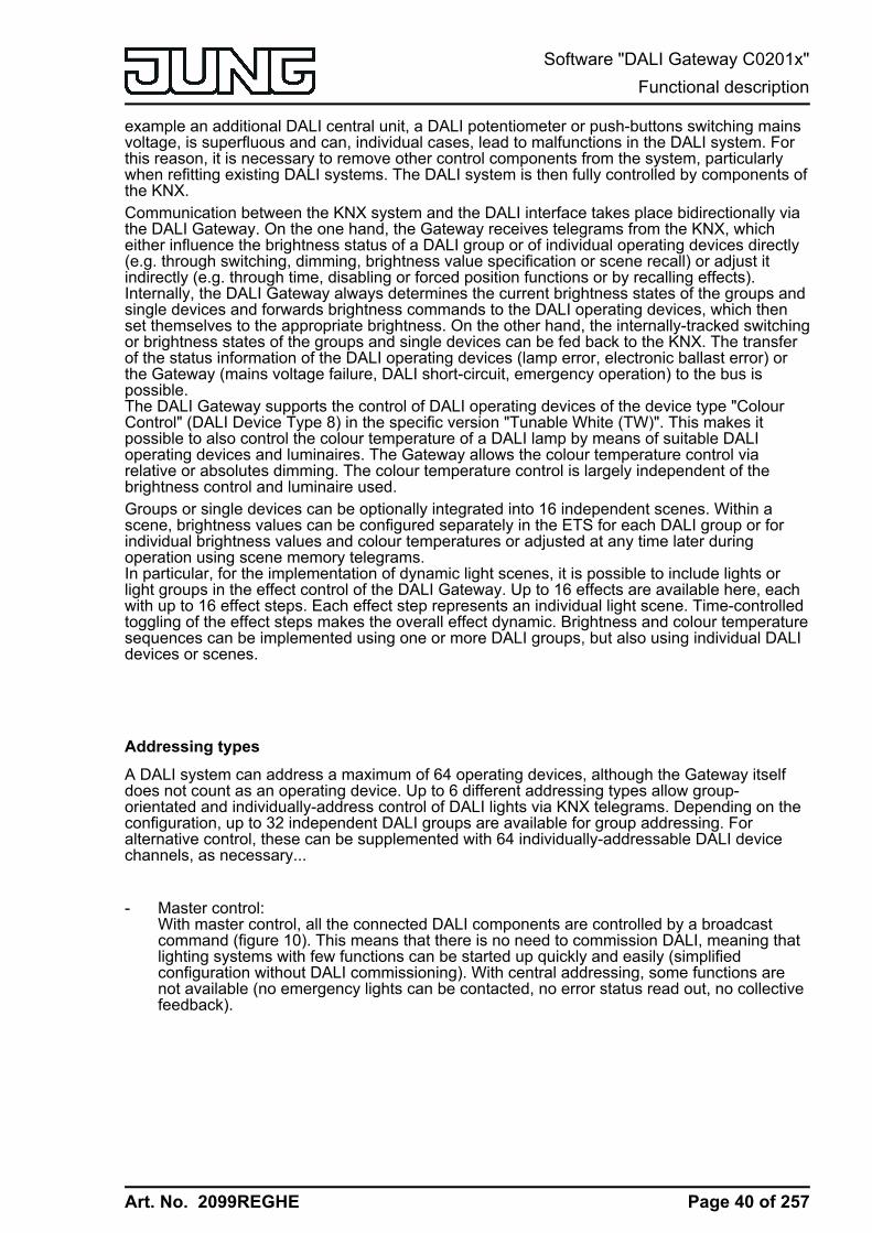
Art. No. 2099REGHE
example an additional DALI central unit, a DALI potentiometer or push-buttons switching mainsvoltage, is superfluous and can, individual cases, lead to malfunctions in the DALI system. Forthis reason, it is necessary to remove other control components from the system, particularlywhen refitting existing DALI systems. The DALI system is then fully controlled by components ofthe KNX.Communication between the KNX system and the DALI interface takes place bidirectionally viathe DALI Gateway. On the one hand, the Gateway receives telegrams from the KNX, whicheither influence the brightness status of a DALI group or of individual operating devices directly(e.g. through switching, dimming, brightness value specification or scene recall) or adjust itindirectly (e.g. through time, disabling or forced position functions or by recalling effects).Internally, the DALI Gateway always determines the current brightness states of the groups andsingle devices and forwards brightness commands to the DALI operating devices, which thenset themselves to the appropriate brightness. On the other hand, the internally-tracked switchingor brightness states of the groups and single devices can be fed back to the KNX. The transferof the status information of the DALI operating devices (lamp error, electronic ballast error) orthe Gateway (mains voltage failure, DALI short-circuit, emergency operation) to the bus ispossible.The DALI Gateway supports the control of DALI operating devices of the device type "ColourControl" (DALI Device Type 8) in the specific version "Tunable White (TW)". This makes itpossible to also control the colour temperature of a DALI lamp by means of suitable DALIoperating devices and luminaires. The Gateway allows the colour temperature control viarelative or absolutes dimming. The colour temperature control is largely independent of thebrightness control and luminaire used.Groups or single devices can be optionally integrated into 16 independent scenes. Within ascene, brightness values can be configured separately in the ETS for each DALI group or forindividual brightness values and colour temperatures or adjusted at any time later duringoperation using scene memory telegrams.In particular, for the implementation of dynamic light scenes, it is possible to include lights orlight groups in the effect control of the DALI Gateway. Up to 16 effects are available here, eachwith up to 16 effect steps. Each effect step represents an individual light scene. Time-controlledtoggling of the effect steps makes the overall effect dynamic. Brightness and colour temperaturesequences can be implemented using one or more DALI groups, but also using individual DALIdevices or scenes.
Addressing types
A DALI system can address a maximum of 64 operating devices, although the Gateway itselfdoes not count as an operating device. Up to 6 different addressing types allow group-orientated and individually-address control of DALI lights via KNX telegrams. Depending on theconfiguration, up to 32 independent DALI groups are available for group addressing. Foralternative control, these can be supplemented with 64 individually-addressable DALI devicechannels, as necessary...
- Master control:With master control, all the connected DALI components are controlled by a broadcastcommand (figure 10). This means that there is no need to commission DALI, meaning thatlighting systems with few functions can be started up quickly and easily (simplifiedconfiguration without DALI commissioning). With central addressing, some functions arenot available (no emergency lights can be contacted, no error status read out, no collectivefeedback).
Page 40 of 257
Software "DALI Gateway C0201x"Functional description
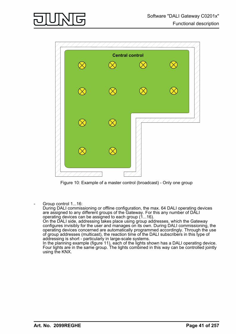
Art. No. 2099REGHE
Central control
Figure 10: Example of a master control (broadcast) - Only one group
- Group control 1...16:During DALI commissioning or offline configuration, the max. 64 DALI operating devicesare assigned to any different groups of the Gateway. For this any number of DALIoperating devices can be assigned to each group (1...16).On the DALI side, addressing takes place using group addresses, which the Gatewayconfigures invisibly for the user and manages on its own. During DALI commissioning, theoperating devices concerned are automatically programmed accordingly. Through the useof group addresses (multicast), the reaction time of the DALI subscribers in this type ofaddressing is short - particularly in large-scale systems.In the planning example (figure 11), each of the lights shown has a DALI operating device.Four lights are in the same group. The lights combined in this way can be controlled jointlyusing the KNX.
Page 41 of 257
Software "DALI Gateway C0201x"Functional description

Art. No. 2099REGHE
Group 1Group 2Group 3
Figure 11: Example of group control with three groups - all lights with group addressing
- Group control 1...32:In this addressing type too, during DALI commissioning or offline configuration, the max. 64DALI operating devices are assigned to different groups of the Gateway. For this, anynumber of DALI operating devices can be assigned to groups 1...16. On the DALI side,addressing takes place using group addresses, meaning that the reaction time of the DALIsubscribers in groups 1...16 is short.In contrast, only up to two DALI operating devices can be assigned to groups 17...32. Sincethere are no DALI group addresses for these groups, DALI addressing takes place usingthe device short addresses, which means that the operating devices are addressed, andthus contacted, individually. In particular, in large systems with multiple subscribersaddressed by short address, the reaction time is slower than with group addressing, asaddressing takes place individually and in sequence.In the planning example (figure 12), each of the lights shown has a DALI operating device.In the right-hand and middle areas of the room are two groups, each with four lights. Here,use of groups 1...16 is advisable. In another area of the room, a total of four lights isintegrated into two further groups. Each of these groups contains two lights. Here, use ofgroups 17...32 is advisable, in particular if the lower groups are to comprise multipleoperating devices (e.g. in other rooms). When integrating up to two lights into a group, it iswise to use groups 17...32, provided that no fast reaction times are expected.If this addressing type is used, the integration of two operating devices each in up to 32groups allows addressing of 64 subscribers via group control.
Page 42 of 257
Software "DALI Gateway C0201x"Functional description

Art. No. 2099REGHE
i The device short addresses are always assigned in the parameter configuration of thesingle devices and can thus be influenced. Short addresses must be unique. This meansthat addresses may not appear multiple times in a DALI system. The ETS plug-in of theDALI Gateway checks the editing of short addresses and checks that they are unique.
Group 18
Group 1Group 2Group 17
Figure 12: Example of group control with four groups -Lights in groups 17 and 18 with individual addresses
- Group control 1...16 and group control 1...64:In this addressing type, the operating devices in groups 1...16 are controlled using DALIgroup addresses, as described above for group control. In addition, other DALI operatingdevices can be addressed individually as single devices. The addressing of these devicestakes place individually using the device short addresses.In the planning example (figure 13), each of the lights shown has a DALI operating device.In the right-hand and middle areas of the room are two groups. Here, use of groups 1...16is advisable. In another area of the room, two more lights are installed, each of which is tobe controlled separately. Here, use of single addressing is advisable.
i DALI operating devices can either be integrated only in single device addressing, oralternatively, in group addressing. It is not possible to control an operating device with bothaddressing types. Operating devices integrated in group control can no longer beaddressed as a single device. The reverse case applies in the same manner.
Page 43 of 257
Software "DALI Gateway C0201x"Functional description
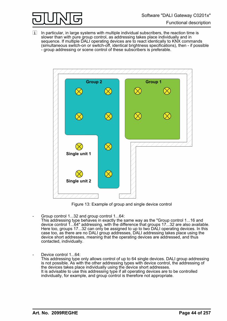
Art. No. 2099REGHE
i In particular, in large systems with multiple individual subscribers, the reaction time isslower than with pure group control, as addressing takes place individually and insequence. If multiple DALI operating devices are to react identically to KNX commands(simultaneous switch-on or switch-off, identical brightness specifications), then - if possible- group addressing or scene control of these subscribers is preferable.
Group 1Group 2
Single unit 1
Single unit 2
Figure 13: Example of group and single device control
- Group control 1...32 and group control 1...64:This addressing type behaves in exactly the same way as the "Group control 1...16 anddevice control 1...64" addressing, with the difference that groups 17...32 are also available.Here too, groups 17...32 can only be assigned to up to two DALI operating devices. In thiscase too, as there are no DALI group addresses, DALI addressing takes place using thedevice short addresses, meaning that the operating devices are addressed, and thuscontacted, individually.
- Device control 1...64:This addressing type only allows control of up to 64 single devices. DALI group addressingis not possible. As with the other addressing types with device control, the addressing ofthe devices takes place individually using the device short addresses.It is advisable to use this addressing type if all operating devices are to be controlledindividually, for example, and group control is therefore not appropriate.
Page 44 of 257
Software "DALI Gateway C0201x"Functional description
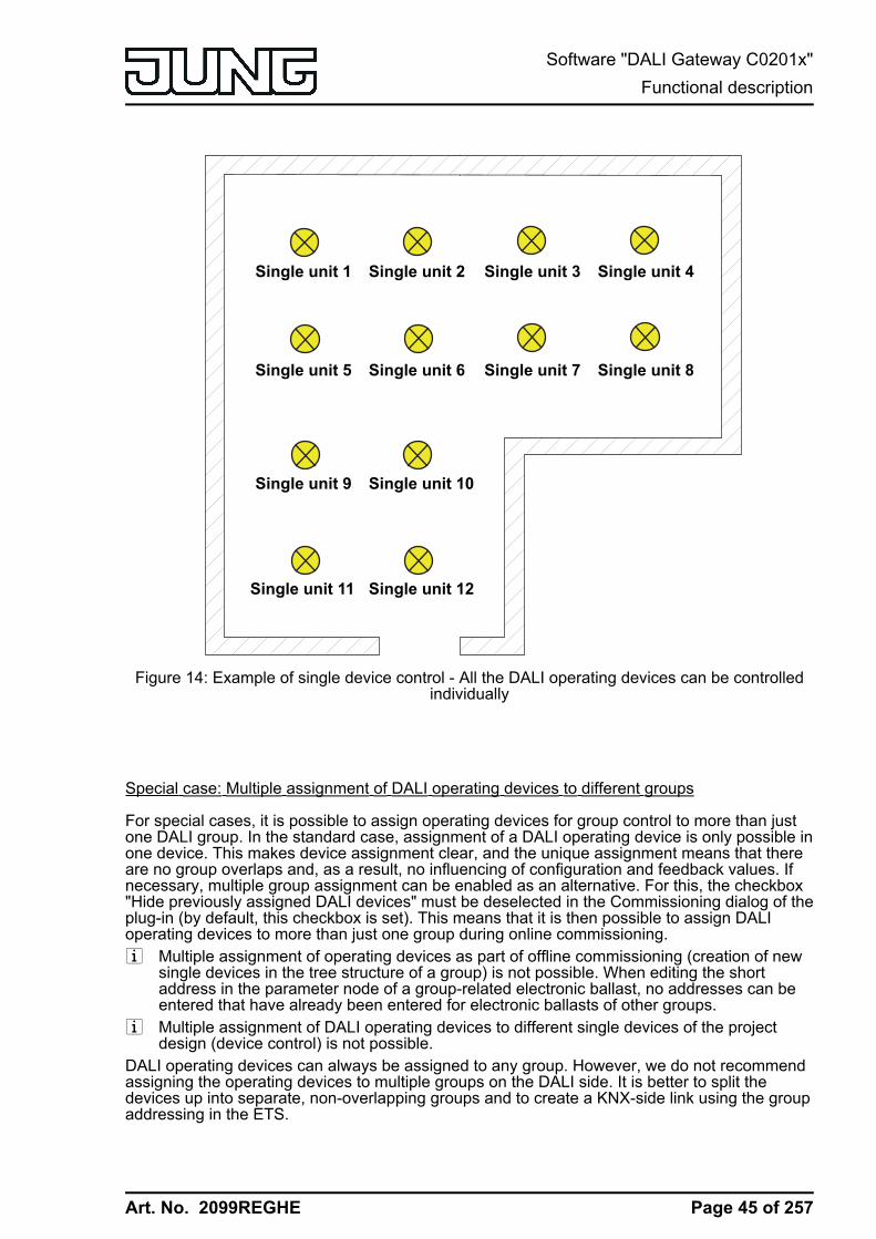
Art. No. 2099REGHE
Single unit 1 Single unit 2 Single unit 3 Single unit 4
Single unit 5 Single unit 6
Single unit 9 Single unit 10
Single unit 11 Single unit 12
Single unit 7 Single unit 8
Figure 14: Example of single device control - All the DALI operating devices can be controlledindividually
Special case: Multiple assignment of DALI operating devices to different groups
For special cases, it is possible to assign operating devices for group control to more than justone DALI group. In the standard case, assignment of a DALI operating device is only possible inone device. This makes device assignment clear, and the unique assignment means that thereare no group overlaps and, as a result, no influencing of configuration and feedback values. Ifnecessary, multiple group assignment can be enabled as an alternative. For this, the checkbox"Hide previously assigned DALI devices" must be deselected in the Commissioning dialog of theplug-in (by default, this checkbox is set). This means that it is then possible to assign DALIoperating devices to more than just one group during online commissioning.i Multiple assignment of operating devices as part of offline commissioning (creation of new
single devices in the tree structure of a group) is not possible. When editing the shortaddress in the parameter node of a group-related electronic ballast, no addresses can beentered that have already been entered for electronic ballasts of other groups.
i Multiple assignment of DALI operating devices to different single devices of the projectdesign (device control) is not possible.
DALI operating devices can always be assigned to any group. However, we do not recommendassigning the operating devices to multiple groups on the DALI side. It is better to split thedevices up into separate, non-overlapping groups and to create a KNX-side link using the groupaddressing in the ETS.
Page 45 of 257
Software "DALI Gateway C0201x"Functional description

Art. No. 2099REGHE
Group 1Group 2
Group 17
Figure 15: Example of multiple assignment of operating devices -Here: Group 1 overlaps with Group 2 and Group 17
i DALI operating devices assigned to multiple groups always set themselves to the mostrecent status set using one of the assigned groups. In this case, feedback of the switchingstatus, brightness value or colour temperature of a group cannot always be clear. Thefollowing examples explain this behaviour (figure 15):Example 1: Group 1 is set to 10 % brightness. After this, Group 2 is dimmed to 20 %brightness. The lights of Group 2 assume the most recently recalled brightness value: 20%. The feedback of Group 1 remains at 10 %, although some of the operating devicesbelonging to the group were set to 20 % brightness.Example 2: Group 1 is switched on and sets itself to the brightness value 100 %. Thestatus of Group 2 internally in the DALI Gateway remains at 0 % brightness (OFF). NowGroup 2 is made brighter. The lights of Group 2 adopt the dimming behaviour (becomingbrighter from minimum brightness), although these lights have already been switched on byGroup 1.
i If DALI operating devices are assigned to multiple groups and these groups were assignedto a shared scene, then all operating devices will adjust to the brightness value or colourtemperature value specified by the group with the highest number.Example: An electronic ballast was assigned to Groups 1 and 2. Both groups are assignedto Scene 1. When the scene is recalled, Group 1 is to set itself to 10 % and Group 2 to 20% brightness. When Scene 1 is recalled, the electronic ballast is set to 20 %, as Group 2has the higher group number.
Page 46 of 257
Software "DALI Gateway C0201x"Functional description
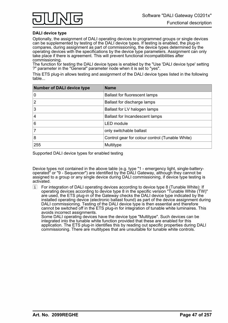
Art. No. 2099REGHE
DALI device typeOptionally, the assignment of DALI operating devices to programmed groups or single devicescan be supplemented by testing of the DALI device types. If testing is enabled, the plug-incompares, during assignment as part of commissioning, the device types determined by theoperating devices with the specifications by the device type parameters. Assignment can onlytake place if there is agreement. This will prevent functional incompatibilities aftercommissioning.The function for testing the DALI device types is enabled by the "Use 'DALI device type' setting?" parameter in the "General" parameter node when it is set to "yes".This ETS plug-in allows testing and assignment of the DALI device types listed in the followingtable...
Number of DALI device type Name0 Ballast for fluorescent lamps
2 Ballast for discharge lamps
3 Ballast for LV halogen lamps
4 Ballast for Incandescent lamps
6 LED module
7 only switchable ballast
8 Control gear for colour control (Tunable White)
255 Multitype
Supported DALI device types for enabled testing
Device types not contained in the above table (e.g. type "1 - emergency light, single-battery-operated" or "9 - Sequencer") are identified by the DALI Gateway, although they cannot beassigned to a group or any single device during DALI commissioning, if device type testing isactivated.i For integration of DALI operating devices according to device type 8 (Tunable White): If
operating devices according to device type 8 in the specific version "Tunable White (TW)"are used, the ETS plug-in of the Gateway checks the DALI device type indicated by theinstalled operating device (electronic ballast found) as part of the device assignment duringDALI commissioning. Testing of the DALI device type is then essential and thereforecannot be switched off in the ETS plug-in for integration of tunable white luminaires. Thisavoids incorrect assignments.Some DALI operating devices have the device type "Multitype". Such devices can beintegrated into the tunable white function provided that these are enabled for thisapplication. The ETS plug-in identifies this by reading out specific properties during DALIcommissioning. There are multitypes that are unsuitable for tunable white controls.
Page 47 of 257
Software "DALI Gateway C0201x"Functional description

Art. No. 2099REGHE
4.2.4.1.2 DALI emergency lighting systemsThe DALI Gateway can be integrated into DALI emergency lighting systems. It allowsinterference-free operation of operating devices, general lighting systems and emergencylighting operating devices of the same DALI system. The device is able to integrate standardDALI operating devices for lighting control according to IEC 62386-101 (DALI System) andIEC 62386-102 (Control Gear) into centrally-supplied emergency lighting systems as anemergency light.
i The statutory and standard specifications vary from country to country. In any event,the user / technical planner should check whether the specific specifications shouldbe maintained.
No emergency lights with special DALI operating devices are used in an emergency lightingsystem, supplied by group or central battery systems. Instead, standard devices are usedaccording to the basic DALI standards. These devices, which are primarily intended to controlgeneral DALI lighting systems, usually only possess one mains voltage connection and do notpossess a battery for self-supply, should the mains voltage fail.
In centrally-supplied emergency lighting systems, a distinction is made as to which parts of theelectrical building installation are supplied by the emergency power supply. When KNX andDALI systems are combined, the following three applications result. In each of the cases, if thegeneral power supply fails, a suitable switching unit must ensure that the system switches to thecentral emergency power supply after detection of the failure, so that the emergency lighting isactivated and functioning...
- Emergency operation only comprises DALI lights:In this application, either all or only individual DALI operating devices are connected to theemergency power supply (figure 16). The KNX system and DALI Gateway are not suppliedwith emergency power, which means that if the mains voltage fails, these subsystems willno longer function. If there is a fault, there is no DALI voltage because the power supply ofthe Gateway is no longer working.Due to the switched-off DALI voltage, the operating devices supplied with emergencycurrent set the "System Failure Level" saved in the device at the beginning of emergencyoperation as the brightness value. This brightness value was written by the DALI Gatewayto the DALI operating devices after ETS commissioning. By default, the "System FailureLevel" is defined by the "Behaviour in case of bus voltage failure" parameter of a group orsingle device. Optionally, this value - irrespective of the behaviour in case of bus voltagefailure - can be set to a separate brightness value for emergency operation.When activating operating devices that support the device type "Colour Control" (DALIDevice Type 8), the effective colour temperature in emergency operation does not changein this configuration. The Gateway initialises the DALI operating devices so that the colourtemperature remains unchanged if the DALI voltage fails.
Page 48 of 257
Software "DALI Gateway C0201x"Functional description
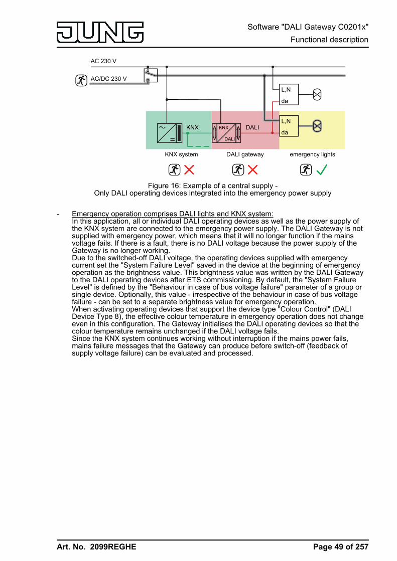
Art. No. 2099REGHE
L,N
da
KNX
DALI
DALI
AC 230 V
AC/DC 230 V
KNX
KNX system DALI gateway emergency lights
L,N
da
Figure 16: Example of a central supply -Only DALI operating devices integrated into the emergency power supply
- Emergency operation comprises DALI lights and KNX system:In this application, all or individual DALI operating devices as well as the power supply ofthe KNX system are connected to the emergency power supply. The DALI Gateway is notsupplied with emergency power, which means that it will no longer function if the mainsvoltage fails. If there is a fault, there is no DALI voltage because the power supply of theGateway is no longer working.Due to the switched-off DALI voltage, the operating devices supplied with emergencycurrent set the "System Failure Level" saved in the device at the beginning of emergencyoperation as the brightness value. This brightness value was written by the DALI Gatewayto the DALI operating devices after ETS commissioning. By default, the "System FailureLevel" is defined by the "Behaviour in case of bus voltage failure" parameter of a group orsingle device. Optionally, this value - irrespective of the behaviour in case of bus voltagefailure - can be set to a separate brightness value for emergency operation.When activating operating devices that support the device type "Colour Control" (DALIDevice Type 8), the effective colour temperature in emergency operation does not changeeven in this configuration. The Gateway initialises the DALI operating devices so that thecolour temperature remains unchanged if the DALI voltage fails.Since the KNX system continues working without interruption if the mains power fails,mains failure messages that the Gateway can produce before switch-off (feedback ofsupply voltage failure) can be evaluated and processed.
Page 49 of 257
Software "DALI Gateway C0201x"Functional description
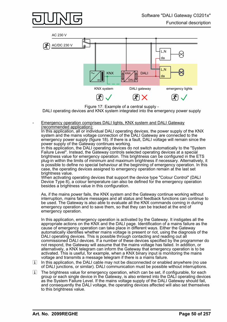
Art. No. 2099REGHE
L,N
da
KNX
DALI
DALI
AC 230 V
AC/DC 230 V
KNX
KNX system DALI gateway emergency lights
L,N
da
Figure 17: Example of a central supply -DALI operating devices and KNX system integrated into the emergency power supply
- Emergency operation comprises DALI lights, KNX system and DALI Gateway(recommended application):In this application, all or individual DALI operating devices, the power supply of the KNXsystem and the mains voltage connection of the DALI Gateway are connected to theemergency power supply (figure 18). If there is a fault, DALI voltage will remain since thepower supply of the Gateway continues working.In this application, the DALI operating devices do not switch automatically to the "SystemFailure Level". Instead, the Gateway controls selected operating devices at a specialbrightness value for emergency operation. This brightness can be configured in the ETSplug-in within the limits of minimum and maximum brightness if necessary. Alternatively, itis possible to define no special behaviour at the beginning of emergency operation. In thiscase, the operating devices assigned to emergency operation remain at the last setbrightness value.When activating operating devices that support the device type "Colour Control" (DALIDevice Type 8), a colour temperature can also be defined for the emergency operationbesides a brightness value in this configuration.
As, if the mains power fails, the KNX system and the Gateway continue working withoutinterruption, mains failure messages and all status and feedback functions can continue tobe used. The Gateway is also able to evaluate all the KNX commands coming in duringemergency operation and to save them, so that they can be tracked at the end ofemergency operation.
In this application, emergency operation is activated by the Gateway. It instigates all theappropriate actions on the KNX and the DALI page. Identification of a mains failure as thecause of emergency operation can take place in different ways. Either the Gatewayautomatically identifies whether mains voltage is present or not, using the diagnosis of theDALI operating devices. This is possible through contacting and reading out allcommissioned DALI devices. If a number of these devices specified by the programmer donot respond, the Gateway will assume that the mains voltage has failed. In addition, oralternatively, a KNX telegram can inform the Gateway that emergency operation is to beactivated. This is useful, for example, when a KNX binary input is monitoring the mainsvoltage and transmits a message telegram if there is a mains failure.
i In this application, the DALI cable may not be disconnected or enabled anywhere (no useof DALI junctions, or similar). DALI communication must be possible without interruptions.
i The brightness value for emergency operation, which can be set, if configurable, for eachgroup or each single device in the Gateway, is also entered into the DALI operating devicesas the System Failure Level. If the mains voltage supply of the DALI Gateway should fail,and consequently the DALI voltage, the operating devices affected will also set themselvesto this brightness value.
Page 50 of 257
Software "DALI Gateway C0201x"Functional description

Art. No. 2099REGHE
L,N
da
KNX
DALI
DALI
AC 230 V
AC/DC 230 V
KNX
KNX system DALI gateway emergency lights
L,N
da
Figure 18: Example of a central supply -DALI operating devices, KNX system and DALI Gateway integrated into the emergency power
supply
Page 51 of 257
Software "DALI Gateway C0201x"Functional description

Art. No. 2099REGHE
4.2.4.1.3 ETS plug-in
Program windowThe setting of all the devices parameter, DALI commissioning and also the DALI test are entirelycarried out by a plug-in embedded in the ETS. The plug-in is a component part of the productdatabase and is installed automatically, when the device is inserted into an ETS project from theproduct catalogue and is accessed. There is no need to install additional software.The plug-in is started by opening the Parameter view of the DALI Gateway. Then the ETS usedwill see the program window of the plug-in.(figure 19).
Figure 19: Program window of the ETS plug-in
The program window is primarily divided up into two areas. The left-hand pane contains all theparameter pages of the group-related, device-related and multi-channel parameters in a treestructure. Configuration pages for commissioning, the import/export function and the DALI testare also available in this window. The individual pages can be selected and opened by clickingthe mouse or navigating with the keyboard. The parameters and operating elements assignedto the parameter page then become visible in the right-hand pane.There are 4 buttons in the lower area of the window. The OK button exits the plug-in and savesthe set parameters and configurations to the ETS database.The Cancel button exits the plug-in, without saving the data to the ETS database. Any changesto the parameter settings are lost. In addition, previously set DALI commissioning parametersare not applied to the ETS database. However, previously performed DALI commissioningremains in the DALI operating devices. This can lead to cancellation operations or dataincompatibility. An information message warns the ETS user, preventing mistaken programcancellations.When pressed, the Standard button resets all the parameters of the DALI Gateway to thestandard values supplied by the manufacturer in the product database. Any changes to theparameter settings deviating from the standard specifications are lost. Any created groups anddevices will be deleted. The parameters of the DALI commissioning ("Hide previously assignedDALI devices", "Compatibility mode for DALI commissioning" and "Partial DALI commissioning")are not reset to the standard configuration". These parameters always remain at the states lastset. Assignments of DALI operating devices to groups or single devices are lost. However,previously performed DALI commissioning remains in the DALI operating devices. For thisreason, when resetting to standard parameters, also perform a reset of the connected DALIsubscribers or commissioning with a new group assignment.When pressed, the Help button opens this product documentation of the DALI Gateway asonline help.
Page 52 of 257
Software "DALI Gateway C0201x"Functional description

Art. No. 2099REGHE
Creating DALI groups or single devicesDepending on the addressing type configuration, up to 32 DALI groups are available for groupaddressing. For alternative control, these can be supplemented with 64 individually-addressableDALI device channels, as necessary. DALI groups and single devices are created in the plug-inand configured separately. At least one group or single device has always been created.Additional groups or devices can be added to the configuration by selecting the appropriateparameter node in the tree view and then executing the command New using the context menu(right mouse-click).(figure 20).
Figure 20: Additional DALI groups (single devices can be added in the same manner)
Created groups or single devices can also be copied using the Copy command of the contextmenu of a group or device node and inserted into the higher-level node as a new group or newsingle device using Insert. Parameter settings are also applied. It is also possible to insert apreviously copied group into an existing group. In so doing, all the parameter settings of theexisting group, although not assigned single devices, are transferred from the copied group.This allows the creation of groups with an identical configuration (e.g. in large DALI systems)quickly and without much work. Copying and insertion into existing nodes can be performed inthe same way for single devices.i It is possible to copy a group and insert it into the parameter node of a single device. For
this, the configuration of the group is applied to the single device. It is also possible to copysingle devices and insert them onto group nodes. Only the parameters supported by thetarget node are copied.
Created groups or single devices can be deleted at any time by selecting the appropriateparameter node in the tree structure and executing the Delete command of the context menu.Note that at least one group and / or single device must always have been created. In addition,a parameter can be used to assign a name to each group and each single device. It is possibleto change a name at a later date using the parameter configuration or, alternatively, by usingthe Rename command in the context menu. We recommend labelling each group and eachsingle device clearly by giving it a name (e.g. "Light strip window, south", "Sports, office,central", etc.). The name may be a maximum of 28 characters and may contain alphanumericand special characters.Each DALI group receives a unique group number (1...32), which is shown in square bracketsbefore the group name. In the case of single devices, the DALI short address (1...64) isdisplayed in square brackets. The DALI short addresses are always assigned in the parameterconfiguration of the single devices and can thus be influenced. Consecutive group numbers aregenerated by the plug-in itself when new groups are created (next free address).With the addition of group and device names, unique naming of DALI operating devices ispossible by referencing the numbers and short addresses. Through the transmission of theunique names to the KNX building visualisation (e.g. control panels), the user is able -particularly during error diagnosis - to identify the lighting components easily. The group and
Page 53 of 257
Software "DALI Gateway C0201x"Functional description

Art. No. 2099REGHE
device numbers are also displayed in the 7-segment display on the front of the device duringactive operation .i Each group and each single device can be configured independently in the plug-in. After
configuration during DALI commissioning, the individual DALI operating devices areprogrammed with the configured short addresses. The configuration of the groups andsingle devices is transmitted to the DALI operating devices when the Gateway is startedafter an ETS programming operation. In so doing, all the operating devices assigned to aDALI group are configured identically. If DALI operating devices are assigned to multiplegroups, these devices will then receive the project design of the group with the highestgroup number.
Creating scenes, effects and effect stepsLights or light groups can optionally be integrated in up to 16 scenes, meaning thatpreprogrammed static light scenes can be recalled. In particular, for the implementation ofdynamic light scenes, it is possible to include lights or light groups in the effect control of theDALI Gateway. Up to 16 effects are available here, each with up to 16 effect steps. Each effectstep represents an individual light scene.Scenes and effects are created in the ETS plug-in and are configured separately. A scene or aneffect can be added to the configuration by selecting the appropriate parameter node in the treeview and then by executing the command New using the context menu (right mouse-click).(figure 21).Up to 15 effect steps can be created for each effect, as necessary. The sixteenth last step of aneffect is always the stop step in the configuration. This is only executed when the effect isstopped automatically after the number of run-throughs has been reached or the user performsthe Stop command. This makes it possible to set a defined lighting state.A new effect step can be added by selecting an effect parameter node in the tree view and thenexecuting the New command in the context menu. This always adds the first step of an effect. Ifsteps already exist, these are always shifted one place when new steps are added. The existingsteps are thus given a new, higher step number (2...15 / 16 = Stop step).i When new effects are created, all the necessary effect steps should always be created
directly, in order to avoid subsequent editing and shifting of the effect sequences due to theadding of new steps.
Page 54 of 257
Software "DALI Gateway C0201x"Functional description

Art. No. 2099REGHE
Figure 21: Adding scenes (effects and effect steps can be added in the same way)
Created scenes and effects can also be copied using the Copy command of the context menuof an appropriate scene or effect parameter node and inserted into the higher-level nodes"Scenes" or "Effects" as a new scene or new effect using Insert. Parameter settings are alsoapplied. It is also possible to insert a previously copied scene or effect into an existing scene oreffect. All the parameter settings are applied without creating a new element.Effect steps can only be copied and inserted into existing steps. This completely transfers theconfiguration of the copied step into another step. This function can be used, for example, totransport existing step configurations into other steps, after new steps have been added,thereby changing the sequence of the light scene.Created scenes, effects and effect steps can be deleted at any time by selecting the appropriateparameter node in the tree structure and executing the Delete command of the context menu. Inaddition, a parameter can be used to assign a name to each scene or effect. It is possible tochange a name at a later date using the parameter configuration or, alternatively, by using theRename command in the context menu. We recommend labelling each scene or effect clearlyby giving it a name (e.g. "Scene TV", "Effect window", etc.). The name may be a maximum of 28characters and may contain alphanumeric and special characters.Each scene and effect receives a unique number (1...16), which is shown in square bracketsbefore the name. This number is only a label within the ETS plug-in for distinguishing clearlybetween the individual scenes and effects, even if they have the same name. In addition,scenes and effects have KNX numbers (1...64). These KNX numbers can be used to recall ascene or a scene memory function and to start and stop the effects using the extension objectsof these functions. Scene and effect numbers do not have to be identical to KNX extensionnumbers. The KNX numbers are configured individually.KNX numbers must be unique. It is not possible to assign the same KNX numbers to multiplescenes. The same applies to the KNX numbers of the effects.In the case of effect steps, the step number (1...15 / 16 = Stop step) is displayed in squarebrackets. This labels the step sequence of an effect run-through directly.
Import and export of templates or backup filesComplete device planning (all parameter settings, KNX group addresses and objectconfiguration) as well as all DALI commissioning parameters (found DALI operating devices,
Page 55 of 257
Software "DALI Gateway C0201x"Functional description

Art. No. 2099REGHE
long and short addresses and group/single device assignments) can be exported to an externalXML file and thus backed up. In addition, an import of previously backed-up data is possible atany time. This makes simple data backup possible, even outside the ETS database. In addition,existing device planning can be downloaded as a template even to other DALI Gateways of thesame type, thus simplifying the configuration of a new device considerably.The import and export function can be executed on the parameter page Import / Export / Printof the plug-in.Pressing the Export button exports the complete current device configuration of the plug-in toan XML file. Before exporting, it is possible to specify the memory location of the file. The plug-in displays the progress of the export operation. The operation may take some time. The lengthof time depends on the number of existing groups and single devices, the created scenes andeffects as well as on the DALI operating devices available.i The data is exported in "*.XML" format. Microsoft XML-Parser 3.0 or higher must be
installed on the PC ("msxml3.dll") in order to export an XML file. An appropriate installationcan be downloaded from the Microsoft website (www.microsoft.com/downloads / searchterm: "msxml"). "MSXML 3.0 Service Pack 4" or a later version is required as theappropriate program package.If the program package is not installed, the plug-in of the DALI Gateway will display an errormessage when the Export command is executed.
Pressing the Import button can download a previously exported XML file to the deviceconfiguration. It should be noted that, during an import operation, the current configuration of theplug-in in the ETS, including all the commissioning parameters of the DALI operating devices, isalways overwritten. For this reason, the plug-in issues a warning of this characteristic before theprocess is executed.(figure 22).
Figure 22: Note before an import operation
After confirmation of the import, the plug-in asks whether the import should take place with orwithout KNX group addresses.(figure 23). In the case of an import without group addresses, theplug-in does not apply any associations between the communication objects and the groupaddresses of the XML file. After the import operation, no group addresses are connected toobjects. Alternatively, an XML import can also be carried out with the application of the KNXgroup addresses saved in the XML file. Before application, the plug-in tests all the groupaddresses of the XML file. If there are no group addresses in the ETS project, they will becreated in the project. If object types do not match (e.g. group address 1/1/1 is linked to 1-bitobjects in the ETS project and with a 1-byte object in the XML file), the addresses concernedwill not be imported from the XML file. The plug-in then displays an information window and liststhe group addresses with a data type conflict. These conflicts must then be resolved manuallyby the ETS user if all group addresses are actually applied.
Page 56 of 257
Software "DALI Gateway C0201x"Functional description

Art. No. 2099REGHE
Figure 23: Import dialog to select an import with or without KNX group addresses
i After the import of an XML file, an ETS programming operation of the application programmust take place so that the configuration data are applied to the Gateway.
i An import operation overwrites all the DALI commissioning parameters (found DALIoperating devices, long and short addresses and group/single device assignments) with thedata of the XML file. It should be noted that only the data saved in the ETS database will becompared. Any previously performed DALI commissioning with programming of the DALIoperating device will remain unchanged in the operating devices. For this reason, after theimport of an XML template, new DALI commissioning must always take place, too, if DALIcommissioning parameters are specified by the XML template other than those mostrecently programmed into the DALI system online. New DALI commissioning is notnecessary if the XML import does not change the commissioning parameters (e.g. duringthe import of an XML backup file of a previously fully-commissioned system when a DALIGateway is replaced).
i Important note for the import of XML files with the ETS3 or the ETS4 of up to Version4.1.6:After the import, the affected device must be unloaded using the ETS. Only then should anETS programming operation be performed. Unloading forces the ETS to perform acomplete download. Only in this way is it guaranteed that all the relevant configuration andcommissioning data from the import are programmed completely into the device.On ETS4 from Version 4.1.7, the programming of all the relevant data is automatic andtime-optimised. There is no need for the unloading operation here.
It is possible to import the XML file of older versions of DALI Gateways (Jung "DALI Gateway"article number 2097 RMD HE or Jung "DALI Gateway Plus" article number 2098 RMD HE), inorder to transfer old configurations to new devices.When importing old templates from the DALI Gateway (2097 RMD HE) taking the functionproperties of these devices into account, the following characteristics and restrictions apply... - Only groups are imported (the addressing type "Group control 1...32" is set).
Page 57 of 257
Software "DALI Gateway C0201x"Functional description
Art. No. 2099REGHE
- Functions that are not available in the old DALI Gateway (e.g. operating hours counter,DALI telegram rate limit, collective feedback, effects) are deactivated after the import.These functions can then be enabled and configured as necessary.
- Communication flags and data point types of objects and transmission flags of groupaddresses are not transferred. Manual adjustments may have to be performed here afterthe XML import if necessary.
When importing templates from the DALI Gateway Plus (2098 RMD HE), the followingcharacteristics and restrictions apply... - No single-battery-operated DALI emergency lights can be imported. When importing a
template that contains single-battery-operated emergency lights (no centrally suppliedemergency lights available), the plug-in displays an information message, deactivates theemergency lighting function completely and sets the devices concerned to "Ballast forfluorescent lamps". When importing a template with centrally supplied and single-battery-operated emergency lights, the plug-in retains the emergency lighting function, configuresthe parameter "emergency light system" to "centrally supplied" and sets the single-battery-operated devices concerned to "Ballast for fluorescent lamps". The XML import applies allsettings unchanged for centrally supplied emergency lights.
- Functions that are not available in the old DALI Gateway Plus (e.g. colour temperaturecontrol) are deactivated after the import. These functions can then be enabled andconfigured as necessary.
i It is not possible to import XML files, exported using the plug-in of the devices described inthis documentation, into the configurations of older devices.
Print functionThe plug-in of the DALI Gateway also offers the option of printing out the complete deviceconfiguration incl. the group/single device programming, the scene and effect configuration andall the DALI commissioning parameters as a configuration report. The Print function can beexecuted on the parameter page Import / Export / Print of the plug-in. When the Print button ispressed, the plug-in asks whether the complete device configuration should be printed out onpaper or only a part of the DALI commissioning parameters, incl. the DALI device names andshort addresses .(figure 24).
Page 58 of 257
Software "DALI Gateway C0201x"Functional description
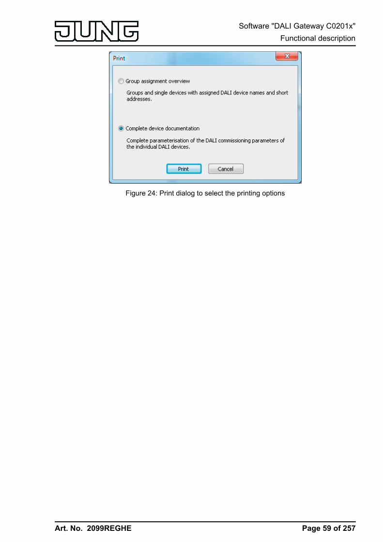
Art. No. 2099REGHE
Figure 24: Print dialog to select the printing options
Page 59 of 257
Software "DALI Gateway C0201x"Functional description
Art. No. 2099REGHE
4.2.4.2 Description of group- and device-independent functions
4.2.4.2.1 DALI communicationThe DALI telegram rate limit can optionally be activated. Firstly, it is then possible to extend theperiod of time between DALI telegrams. Secondly, the initialisation behaviour of the Gatewaycan be influenced. By using the DALI telegram rate limit, it is possible to adapt thecommunication behaviour of the Gateway to problematic or non-DALI-conformant operatingdevices to a great extent.The DALI telegram rate limit is activated and configured in the parameter node "General ->DALI communication".
Time delay between two DALI telegramsIn accordance with the valid DALI standard (IEC 82386-101/102 Ed. 1), pauses of at least 9.15ms must be maintained between the transmissions of individual DALI telegrams to the operatingdevices. To optionally reduce the telegram load for the DALI operating devices and thus reducethe likelihood of errors on the part of some electronic ballasts, it is possible to increase thepause time between telegrams of the DALI Gateway to the operation device by a multiple of theminimum pause time (figure 25). This produces a telegram rate limit, which can adjustedindividually using the parameter "Minimum delay time between two DALI telegrams" in theparameter node "General -> DALI communication" in the range 1...5 in steps of 0.5. For thisparameter to be visible, the DALI telegram rate limit must be active on the same parameterpage.Extending the pause time between the telegrams gives the operating devices more time to reactto the commands of the DALI Gateway. However, this also delays the reaction time of theoverall DALI system when controlled by KNX telegrams and also during DALI commissioning ora DALI test. As a result, large time factors should be avoided in the delay time parameter,unless explicitly required.i The approved pause time between telegrams from the DALI Gateway to the DALI
operating devices and the matching response is within a range of 2.91 ms and 9.15 ms.This time period is required by the operating devices and cannot be influenced to any greatextent by the Gateway.
telegrams
(1...5) x 9.15 ms
gateway
t
gateway gateway ballast...
2.91 ... 9.15 ms
Figure 25: Pause times between DALI telegrams
Delay time after mains voltage return to DALIAfter the mains voltage supply is switched on, depending on the their type, DALI operatingdevices usually require different lengths of time to initialise themselves and thus to react tocommands of the DALI Gateway. To ensure that no commands of the Gateway to the operatingdevices are lost after mains voltage return - because they are still initialising - it is possible toactivate a delay as an option. This delay is defined within a range of 0...30 seconds using theparameter "Delay time after mains voltage return to DALI", which is available in the parameter
Page 60 of 257
Software "DALI Gateway C0201x"Functional description

Art. No. 2099REGHE
node "General -> DALI communication" when a DALI telegram rate limit is activated.The delay time after mains voltage return delays the start of the application of the DALIGateway after the mains voltage supply is switched on as well as after an ETS programmingoperation and thus delays the execution of the configured behaviour after bus voltage returnand all other automatic reactions (e.g. feedback messages) after a device reset. No DALItelegrams are transmitted by the Gateway in this state. "- -" is displayed on the 7-segmentdisplay on the front panel of the device in order to signal that the device is not yet ready foroperation.KNX communication is also possible during the delay time. This allows control of groups andsingle devices as well as of scenes and effects and the specification of commands. However,these are only executed once the delay time on the DALI page has elapsed. Only the lastcommand relative to a group, a single device, a scene or an effect is ever executed!i If KNX telegrams for groups or single devices are received during Gateway initialisation,
the device will perform the most recently specified command and not the configuredbehaviour after bus voltage return.
i The delay time after mains voltage return to DALI is not required if the initialisation time ofthe DALI operating devices is shorter than that of the DALI Gateway. In this case, theparameter should be set to the value "0". If the operating devices initialise more quicklythan the Gateway, they will activate the programmed "Power-On Level" before the Gatewaytransmits other brightness commands. After mains voltage return, this allows theobservation of short-time changes to the brightness states in the DALI system.
i Should only the mains voltage supply of the Gateway fail, the operating devices will setthemselves to the "System Failure Level". After return of the mains voltage supply, theDALI Gateway - once the delay has elapsed - then transmits commands to the DALI pagein accordance with the configured behaviour ("Behaviour after bus voltage return") or thelast KNX specification.
Page 61 of 257
Software "DALI Gateway C0201x"Functional description

Art. No. 2099REGHE
4.2.4.2.2 DALI error messagesThe DALI Gateway allows feedback of various error states. This means that the generalfeedback of an existing error in the DALI system, the feedback of the error status of individualoperating devices and messages on the state of the supply voltage and a short-circuit on theDALI cable can be configured independently of one another using a KNX telegram.
Feedback of error status in DALI systemThe DALI Gateway allows the feedback of the error status of DALI operating devices. (seepage 63-64). If individual evaluation and display of the error status of individual electronicballasts or DALI groups is not required or is to be supplemented with a feedback function,independent of the electronic ballast, it is possible to use the general feedback of the "Errorstatus in the DALI system". This feedback has a separate 1-bit communication object, whichallows the signalling of a general error in the DALI installation. The DALI Gateway sets theobject value to "ON" as soon as it detects an error in a previously commissioned DALI operatingdevice. Here, it is irrelevant which error was identified by the Gateway (lamp error, electronicballast error, converter error). The Gateway only resets the object value to "OFF" when all thepreviously identified errors were eliminated.To use this feedback function, the parameter "Feedback 'Error status in the DALI system' ?" inthe "General -> DALI error messages" parameter node must be configured to the setting"Yes...". The parameter "Type of feedback" determines whether the feedback is an activetransmitter or is passive (general error status must be polled).
Setting feedback of the error status in DALI systemThe feedback of the general error status can be used as an active message object or as apassive status object. As an active message object, the feedback information is transmitted tothe bus whenever the status changes. In the function as a passive status object, there is noautomatic telegram transmission. In this case, the object value must be read out. The ETSautomatically sets the object communication flags required for proper functioning.The parameter "Type of feedback" in the parameter node "General -> DALI error messages"defines the function of the feedback object "Error status in the DALI system".o Set the parameter to "Active signalling object".
The general error status is transmitted as soon as the state changes.i A general error saved in the DALI Gateway is lost when the mains voltage fails. For this
reason, after all the errors have been eliminated by switching the mains voltage off on theDALI Gateway and switching it back on again, no feedback is transmitted.
i The DALI Gateway initialises after switching on the mains power supply or after an ETSprogramming operation. If a DALI error is detected in this state, the Gateway willimmediately transmit an appropriate feedback telegram. The only time feedback is not sentto the bus automatically is after bus voltage return (mains voltage switched-on permanentlyon the DALI Gateway during bus failure).
o Set the parameter to "Passive status object".The general error status will be transmitted in response only if the feedback object is readout by the bus.
Optionally, the general error status can be transmitted repeatedly, if, after a previously identifiedDALI error, further errors are detected on the same or other operating devices. The parameter"Telegram repetition on new error in DALI system ?" in the parameter node "General -> DALIerror messages" specifies the behaviour of the general error status feedback for new errors.o Set the parameter to "yes".
The general error status is transmitted as "1 - ON" for each new error.
Page 62 of 257
Software "DALI Gateway C0201x"Functional description

Art. No. 2099REGHE
o Set the parameter to "no".The general error status is transmitted repeatedly for new errors. Telegrams are onlytransmitted again via the object "Error status in the DALI system", when no more errors arepresent.
Feedback Error status per DALI operating deviceThe DALI Gateway allows the feedback of the individual error status of DALI operating devicesin up to two different data formats. To use this feedback function, the parameter "Feedback'Error status per DALI operating device' ?" in the "General -> DALI error messages" parameternode must be set to the setting "Yes...". assigned automatically. Here, it is possible to definewhether the feedback is an active transmitter or is passive (error status must be polled).The parameter "Feedback data format" determines whether only a 1-byte object (according toKNX DPT 238.600), a 2-byte object (according to KNX DPT 237.600) or a combination of bothobjects is used.The status information "Lamp error" or "Error in operating device (e.g. electronic ballast error)"is transmitted to the Gateway by the DALI components if there is an error, and is saved there.The DALI Gateway makes all the status information about the KNX-side error status objectsavailable. The object values are evaluated in bit-orientated fashion according to the selecteddata format. A feedback telegram always transmits the status information of only one DALIoperating device.As the master in the DALI system, the DALI Gateway - as soon as it is ready for operation -polls the status of the commissioned electronic ballasts (slaves) cyclically every second. Asystem with a maximum of 64 DALI devices can identify an error after 63 seconds at the latest.Once an error has occurred in the operating device, it must be eliminated (switch off the mainsvoltage to the appropriate DALI subscriber and observe the manufacturer's information!). TheDALI Gateway detects an eliminated error automatically after commissioning of the repaireddevice and resets the error state in the feedback.
1-byte error statusBits 0...5 of the 1-byte error status telegram use the electronic ballast number to indicate towhich device the signalled error relates. The electronic ballast numbers of the error status arederived directly from the short addresses of the DALI subscribers. An electronic ballast number(0...63) corresponds to a short address (1...64) minus "1" (example: Short address = "1" ->Electronic ballast number in the error status telegram = "0").i When an error status is displayed, it is irrelevant whether the electronic ballast was
assigned to a single device or a group during project design.
bits
number electronic ballast (0...63)
0 = no lamp errpor / 1 = lamp error
7 6 5 4 3 2 1 0
0 = no electronic ballast error / 1 = electronic ballast error
Figure 26: Telegram structure, 1-byte error status
Bit 6 is set when the appropriate electronic ballast signals a lamp error (e.g. defective light,cable break to lamp socket). In an error-free lamp state, this bit is deleted ("0").Bit 7 is set when the electronic ballast signals a general error (e.g. internal electronic ballasterror). In an error-free device state, this bit is deleted ("0").Bits 6 and 7 are set when the appropriate device could not be contacted by the DALI Gateway(e.g. device disconnected from the DALI cable, mains voltage on the electronic ballast switchedoff).
Page 63 of 257
Software "DALI Gateway C0201x"Functional description

Art. No. 2099REGHE
2-byte error statusIn this data format too, Bits 0...5 use the electronic ballast number to indicate to which devicethe signalled error relates. The electronic ballast numbers of the error status are derived directlyfrom the short addresses of the DALI subscribers. An electronic ballast number (0...63)corresponds to a short address (1...64) minus "1" (example: Short address = "1" -> Electronicballast number in the error status telegram = "0").Alternatively, the 2-byte error status can be used to display the collective error state of all theoperating devices of a DALI group. For this, the error bits of the individual electronic ballast arecollected and evaluated by the Gateway. If any error bit is set in at least one electronic ballast ofthe group, then the same error bit will also be set in the feedback telegram.To make it possible to distinguish whether the feedback is addressing an electronic ballast or agroup, the error status telegram contains Bit 6. This bit indicates whether a single device ("0") ora group ("1") is addressed. When a group is addressed, Bits 0...5 must contain the groupnumber. A group number (0...15) corresponds to a DALI group number (1...16) minus "1"(example: DALI group number = "1" -> Group number in the error status telegram = "0").Bit 7 in the telegram indicates whether this is a request telegram ("1") with passive transmission,or, alternatively, an actively-transmitting telegram, or an answer to a request telegram ("0").i When the error status of an electronic ballast is displayed, it is irrelevant whether the
operating device was assigned to a single device or a group in the project design. In thecase of active telegram transmission, if an error has been identified, only the error statusfor an individual electronic ballast is generally transmitted and not for a group, provided thatthe appropriate electronic ballast is also assigned to a group.
Figure 27: Telegram structure, 2-byte KNX error status
Bit 8 is set when the appropriate electronic ballast or the group signals a lamp error (e.g.defective light, cable break to lamp socket). In an error-free lamp state, this bit is deleted ("0").Bit 9 is set when the electronic ballast or the group signals a general error (e.g. internalelectronic ballast error). In an error-free device state, this bit is deleted ("0").Bits 8 and 9 are set when the appropriate device or an electronic ballast of a group could not becontacted by the DALI Gateway (e.g. device disconnected from the DALI cable, mains voltageon the electronic ballast switched off).
Setting feedback for error status per DALI operating deviceFirstly, it must be specified whether the 1-byte or 2-byte error status is used, or a combination ofboth objects.o Set the parameter "Data format of feedback" on the parameter page "General -> DALI error
messages" to "Only 2-byte KNX object".In accordance with KNX DPT 237.600, only the 2-byte object is available. This object canbe used both actively and passively (request telegram) and should preferably be used inaccordance with KNX specification.
o Set the parameter "Data format of feedback" to "Only 1-byte object".
Page 64 of 257
Software "DALI Gateway C0201x"Functional description
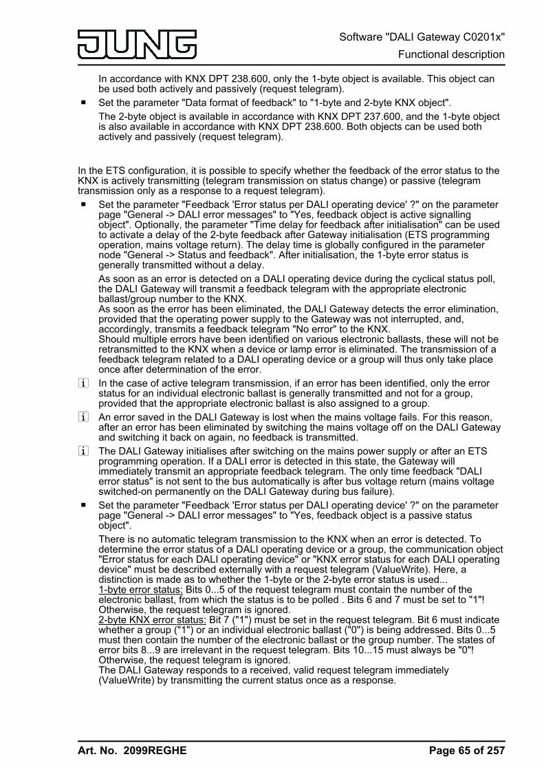
Art. No. 2099REGHE
In accordance with KNX DPT 238.600, only the 1-byte object is available. This object canbe used both actively and passively (request telegram).
o Set the parameter "Data format of feedback" to "1-byte and 2-byte KNX object".The 2-byte object is available in accordance with KNX DPT 237.600, and the 1-byte objectis also available in accordance with KNX DPT 238.600. Both objects can be used bothactively and passively (request telegram).
In the ETS configuration, it is possible to specify whether the feedback of the error status to theKNX is actively transmitting (telegram transmission on status change) or passive (telegramtransmission only as a response to a request telegram).o Set the parameter "Feedback 'Error status per DALI operating device' ?" on the parameter
page "General -> DALI error messages" to "Yes, feedback object is active signallingobject". Optionally, the parameter "Time delay for feedback after initialisation" can be usedto activate a delay of the 2-byte feedback after Gateway initialisation (ETS programmingoperation, mains voltage return). The delay time is globally configured in the parameternode "General -> Status and feedback". After initialisation, the 1-byte error status isgenerally transmitted without a delay.As soon as an error is detected on a DALI operating device during the cyclical status poll,the DALI Gateway will transmit a feedback telegram with the appropriate electronicballast/group number to the KNX.As soon as the error has been eliminated, the DALI Gateway detects the error elimination,provided that the operating power supply to the Gateway was not interrupted, and,accordingly, transmits a feedback telegram "No error" to the KNX.Should multiple errors have been identified on various electronic ballasts, these will not beretransmitted to the KNX when a device or lamp error is eliminated. The transmission of afeedback telegram related to a DALI operating device or a group will thus only take placeonce after determination of the error.
i In the case of active telegram transmission, if an error has been identified, only the errorstatus for an individual electronic ballast is generally transmitted and not for a group,provided that the appropriate electronic ballast is also assigned to a group.
i An error saved in the DALI Gateway is lost when the mains voltage fails. For this reason,after an error has been eliminated by switching the mains voltage off on the DALI Gatewayand switching it back on again, no feedback is transmitted.
i The DALI Gateway initialises after switching on the mains power supply or after an ETSprogramming operation. If a DALI error is detected in this state, the Gateway willimmediately transmit an appropriate feedback telegram. The only time feedback "DALIerror status" is not sent to the bus automatically is after bus voltage return (mains voltageswitched-on permanently on the DALI Gateway during bus failure).
o Set the parameter "Feedback 'Error status per DALI operating device' ?" on the parameterpage "General -> DALI error messages" to "Yes, feedback object is a passive statusobject".There is no automatic telegram transmission to the KNX when an error is detected. Todetermine the error status of a DALI operating device or a group, the communication object"Error status for each DALI operating device" or "KNX error status for each DALI operatingdevice" must be described externally with a request telegram (ValueWrite). Here, adistinction is made as to whether the 1-byte or the 2-byte error status is used...1-byte error status: Bits 0...5 of the request telegram must contain the number of theelectronic ballast, from which the status is to be polled . Bits 6 and 7 must be set to "1"!Otherwise, the request telegram is ignored.2-byte KNX error status: Bit 7 ("1") must be set in the request telegram. Bit 6 must indicatewhether a group ("1") or an individual electronic ballast ("0") is being addressed. Bits 0...5must then contain the number of the electronic ballast or the group number. The states oferror bits 8...9 are irrelevant in the request telegram. Bits 10...15 must always be "0"!Otherwise, the request telegram is ignored.The DALI Gateway responds to a received, valid request telegram immediately(ValueWrite) by transmitting the current status once as a response.
Page 65 of 257
Software "DALI Gateway C0201x"Functional description
Art. No. 2099REGHE
o Set the parameter "Feedback 'Error status per DALI operating device' ?" on the parameterpage "General -> DALI error messages" to "no".The feedback of the error status per DALI operating device is deactivated. Nocommunication object is available for this function.
i Request telegrams to electronic ballast or group numbers, which are not configured in theDALI system and are thus not available, are always answered with deleted error bits.Request telegrams to group numbers greater than 15 (DALI group number greater than 16)are never answered.
i A read telegram (ValueRead) to the communication object "Error status per DALI operatingdevice" or "KNX error status per DALI operating device" is answered, if the Read flag is set,by the DALI Gateway transmitting the most recently updated object value(ValueResponse). This means that DALI operating devices cannot be polled clearly.
Feedback for mains voltage supply on the DALI GatewayThe DALI Gateway can monitor its supply voltage at the mains voltage connection. If there is afailure, the Gateway is able to transmit a message telegram to the KNX before stoppingoperation, provided that the bus voltage is uninterrupted. Optionally, the switch-on of the mainsvoltage supply can also be fed back.If the mains voltage supplies of the Gateway and the connected DALI operating devices areconnected to the same circuit, the operating state of the entire DALI system which is notsupplied with emergency current can be monitored on the KNX through the evaluation of themains voltage feedback.The DALI Gateway uses the 1-bit communication object "Voltage failure in the DALI system" tofeed back a voltage failure or return. The telegram polarity of this object is fixed: Mains voltageavailable = 0, Mains voltage failure = 1.
Setting feedback for mains voltage supplyIn the ETS configuration, it is possible to specify whether only a failure of the mains voltagesupply of the DALI Gateway is fed back to the KNX or whether mains voltage return is also fedback. Telegram transmission is always actively transmitting. As soon as there is a change ofstate in the mains voltage, a feedback telegram is transmitted once. The parameter "Feedback,DALI Gateway supply voltage failure/return ?" in the "General -> DALI error messages"parameter node defines the behaviour of mains voltage monitoring.o Set the parameter to "Yes (only on voltage failure)".
If a mains voltage failure is detected on the DALI Gateway, the Gateway will immediatelytransmit a feedback telegram. It stops operation just a few seconds later.
o Set the parameter to "Yes (on voltage failure and return)".If a mains voltage failure is detected on the DALI Gateway, the Gateway will immediatelytransmit a feedback telegram. It stops operation just a few seconds later. The DALIGateway initialises when the mains power supply is switched on. Then it transmits onefeedback telegram and signals that the mains voltage is switched on.
o Set the parameter to "no".The feedback of the state of the mains voltage supply is deactivated. The communicationobject is hidden.
i The feedback of a mains voltage failure can only be transmitted when the bus voltage isconnected and switched on at the time of the failure. If, at the time of mains return, no busvoltage is connected or switched on, no feedback for mains voltage return will betransmitted either. The feedback is saved, however, which means that it is transmitted laterwhen the bus voltage is switched on.
Page 66 of 257
Software "DALI Gateway C0201x"Functional description
Art. No. 2099REGHE
i The feedback telegram can be transmitted to the bus automatically after bus voltage returnor after programming with the ETS if there is mains voltage on the DALI Gateway.
Feedback for DALI short-circuitThe DALI Gateway detects short-circuits on the DALI cable, as may occur in the case of aninstallation error. As soon as a short-circuit is identified on the DALI cable when the mainspower supply is switched on, the DALI Gateway transmits feedback to the KNX when thefeedback function for DALI short-circuits is enabled.The DALI Gateway uses the 1-bit communication object "Short-circuit in the DALI system" tofeed back a DALI short-circuit. The telegram polarity of this object is fixed: No short-circuit = 0,Short-circuit = 1.
Setting feedback for DALI short-circuitIn the ETS configuration, it is possible to specify whether DALI short-circuit feedback is to betransmitted to the KNX. When enabled, telegram transmission is always actively transmitting. Assoon as a short-circuit has been detected and eliminated, the Gateway will transmit onefeedback telegram without a delay. The parameter "Feedback DALI short-circuit ?" in the"General -> DALI error messages" parameter node defines the behaviour of mains voltagemonitoring.o Set the parameter to "yes".
The DALI short-circuit feedback is activated and the communication object enabled.o Set the parameter to "no".
The DALI short-circuit feedback is deactivated. The communication object is hidden.i The connected DALI operating devices also react to a short-circuit in the DALI cable. The
devices set themselves to the specified "System Failure Level". By default, this brightnessvalue is defined by the "Behaviour in case of bus voltage failure" parameter of a group or asingle device. Optionally, this value can - irrespective of the behaviour in case of busvoltage return - be set to a separate brightness value for emergency operation . (seepage 155).
i Since the brightness of the connected DALI operating devices might possibly change ifthere is a short-circuit, the DALI Gateway also transmits feedback to the bus for theswitching status and brightness value if these feedback functions are enabled.
i The feedback of a DALI short-circuit can only be transmitted when the bus voltage isconnected and switched on at the time of the short-circuit. If no bus voltage is connected orswitched on at the time of the short-circuit, no feedback for mains voltage return will betransmitted either. Feedback is saved, however, which means that it is transmitted laterwhen the bus voltage is switched on.
i The DALI Gateway initialises after switching on the mains power supply or after an ETSprogramming operation. If a short-circuit on the DALI cable is detected in this state, theGateway will immediately transmit an appropriate feedback telegram. After bus voltagereturn (mains voltage switched-on permanently on the DALI Gateway during bus failure),the feedback is not sent to the bus automatically.
Page 67 of 257
Software "DALI Gateway C0201x"Functional description
Art. No. 2099REGHE
4.2.4.2.3 Status and feedbacks
Delay after bus/mains voltage returnTo reduce telegram traffic on the bus line after the bus voltage (bus reset) or the mains voltagesupply is switched on, after connection of the device to the bus line or after programming withthe ETS, it is possible to delay all actively transmitted feedback telegrams of the Gateway. Todo this, a delay time can be specified for multiple functions (parameter "Time delay forfeedbacks after bus return for groups and devices" in the parameter node "General -> Statusand feedback"). Only after the configured time elapses are feedback telegrams for initialisationtransmitted to the bus.It is possible to configure separately which of the feedback telegrams are actually delayed foreach feedback function.i The delay has no effect on the behaviour of the individual groups or single devices and not
on other functions of the device either. Only the feedback telegrams are delayed. Groupsand single devices can also be activated during the delay after bus voltage return.
i A setting of "0" for the delay after bus voltage return deactivates the delaying functionaltogether. In this case, all feedback telegrams, if actively transmitted, will be transmitted tothe bus without any delay.
i The messages "Error status in DALI system", "Error status per DALI operating device" (only1 byte), "Short-circuit in the DALI system" or "Voltage failure in the DALI system" arealways transmitted without a time delay.
Delaying feedbackOnly feedbacks that are enabled and set as actively transmitting can be configured with regardto the transmitting behaviour after bus voltage return.o Set the parameter "Time delay for feedback telegram after bus voltage return" to "yes". The
parameter is on the parameter page of the corresponding switching status or brightnessvalue feedback of a group or a single device.In this case, after bus voltage return the feedback telegram is first transmitted to the busafter the end of the delay time. Alternatively (setting "No"), a feedback telegram istransmitted to the bus without time delay immediately after bus voltage return .
Collective feedbackAfter central commands or after bus/mains voltage return, a KNX line is generally heavily loadedby data traffic as many bus devices are transmitting the state of their communication objects bymeans of feedback telegrams. This effect occurs particularly when using visualisations.Collective feedback of the Gateway can be used to keep the telegram load low duringinitialisation.The collective feedback summarises the switching states of the DALI groups and single devicesin bit-orientated form (figure 28). Up to 6 separate 4-byte communication objects according toKNX DPT 27.001 are available for this, depending on the set addressing type. Each of theseobjects can visualise the switching state of up to 16 groups or devices.
Page 68 of 257
Software "DALI Gateway C0201x"Functional description

Art. No. 2099REGHE
ma
sk g
rou
p 1
ma
sk g
rou
p 2
ma
sk g
rou
p 3
ma
sk g
rou
p 4
ma
sk g
rou
p 5
ma
sk g
rou
p 6
ma
sk g
rou
p 7
ma
sk g
rou
p 8
ma
sk g
rou
p 9
ma
sk g
rou
p 1
0
ma
sk g
rou
p 1
1
ma
sk g
rou
p 1
2
ma
sk g
rou
p 1
3
ma
sk g
rou
p 1
4
ma
sk g
rou
p 1
5
ma
sk g
rou
p 1
6
gro
up
1
gro
up
2
gro
up
3
gro
up
4
gro
up
5
gro
up
6
gro
up
7
gro
up
8
gro
up
9
gro
up
10
gro
up
11
gro
up
12
gro
up
13
gro
up
14
gro
up
15
gro
up
16
byte 1byte 2byte 3byte 4
M M S S
012345678910111213141516171819202122232425262728293031
Figure 28: Structure of the objects of the collective feedback, using the example of the objectfor Groups 1-16
It is possible to show up to 16 groups or single devices and thus up to 16 different switchingstates logically in a 4-byte object. Each group or each single device has one bit representing theswitching state ("S" bit) and another one defining the masking ("M" bit). The "S" bits correspondto the logical non-inverted switching states of the groups or devices and are either "1" (on) or "0"(off). The M bits are "1" when the corresponding group or the appropriate single device hasbeen created in the project design of the Gateway. Similarly, M bits are "0" when groups ordevices are not available. In this case, the corresponding "S" bits are continuously "0", as thereis no switching status.After a device reset (ETS programming operation, bus or mains voltage return), the Gatewayalways transmits all the collective feedback according to the configured addressing type,provided that the objects are configured as actively transmitting. If only individual switchingstates change in Gateway operation, only the affected collective feedback objects are updated.
The following example object value formats result...Groups 1 to 4 available: "00 0F 00 0x", x = switching states-> Group 1 and 2 ON: "00 0F 00 03" / Group 1 and 3 ON: "00 0F 00 05"
Groups 1 to 6 available: "00 3F 00 xx", x = switching states-> Group 1 and 2 ON: "00 3F 00 03" / Group 1 and 5 ON: "00 3F 00 11"
Groups 1 to 4 and 10 to 12 available: "0E 0F 0x 0x", x = switching states-> Group 1 and 4 ON: "0E 0F 00 09" / Group 1 and 10 ON: "0E 0F 02 01"
Use of the collective feedback would be possible in appropriate visualisation applications - forexample in public buildings such as schools or hospitals - where the switching states of theactuators are displayed centrally and no separate switching status is displayed at the controlsections. In such applications the collective feedback can replace the 1 bit individual feedbacksand thereby significantly reduce the bus load.
Activate collective feedbackCollective feedback is a global device function and can be enabled in the parameter node"General -> Status and feedback".o Set the parameter "Collective feedback switching status ?" to "yes".
Collective feedback is enabled. The collective feedback objects become visible in the ETS.Depending on the configured addressing type, up to 6 objects are displayed for groups and/ or single devices.
Page 69 of 257
Software "DALI Gateway C0201x"Functional description
Art. No. 2099REGHE
o Set the parameter to "no".Collective feedback is deactivated. No collective feedback objects are available.
Setting the update of collective feedbackIn the ETS plug-in, you can specify when the Gateway should update the feedback values forthe collective feedback, in the case of an actively transmitting communication object. The objectvalue updated by the Gateway is then signalled actively to the bus.The parameter "Updating of the object value for collective feedback" is created in the parameternode "General -> Status and Feedback".Collective feedback must be enabled and the feedback type set to "Active message object".o Set the parameter to "After each update of the inputs".
The Gateway updates the feedback values in the collective feedback once a new telegramis received on the input objects "Switching" or "Central switching" for groups or singledevices. With actively transmitting feedback objects, a new telegram is also then activelytransmitted to the bus each time. The telegram value of the feedback does not necessarilyhave to change in the process. Hence, corresponding collective feedbacks are alsogenerated, e.g. for cyclical telegrams to the "Switching" objects.
o Set the parameter to "Only if the feedback value changes".The Gateway only updates the feedback values in the collective feedback objects when thetelegram values of the inputs also change. If telegram values of the feedback do notchange (e.g. in the case of cyclical telegrams to the "Switching" objects with the sametelegram value), the feedback then remains unchanged. Consequently, in the case ofactively transmitting feedback objects, no telegram with the same content will betransmitted repeatedly either.
Collective feedback typeCollective feedback can take place in the form of active message objects or passive statusobjects. In the case of active message objects, the feedback is transmitted to the bus wheneverthe status contained therein changes. In the function as a passive status object, there is noautomatic telegram transmission. In this case, the object values must be read out. The ETSautomatically sets the communication flags of the objects required for proper functioning.Collective feedback must be enabled.o Set the parameter "Type of collective feedback" in the parameter node "General -> Status
and Feedback" to "Active signalling object".The Gateway transmits the collective feedback automatically when the object value isupdated. After a device reset (ETS programming operation, bus or mains voltage return),all the collective feedback is transmitted according to the configured addressing type. Ifonly individual switching states change in Gateway operation, only the object values of theaffected collective feedback objects are transmitted to the bus as well.
o Set the parameter to "Passive status object".Collective feedback will only be transmitted in response if the appropriate object is read outfrom the bus. No automatic telegram transmission of the collective feedback takes placeafter bus or mains voltage return or after programming with the ETS.
Setting collective feedback after bus/mains voltage return or after programming with theETSIf used as an active message object, the states of the collective feedback are transmitted to thebus after bus or mains voltage return or after programming with the ETS. In these cases, the
Page 70 of 257
Software "DALI Gateway C0201x"Functional description
Art. No. 2099REGHE
feedback telegram can be time-delayed with the delay being preset globally for all groups andsingle devices together (see page 68).Collective feedback must be enabled and the feedback type set to "Active message object".o Set the parameter "Time delay for feedback telegram after bus voltage return" to "Yes".
The collective feedback objects are transmitted with a delay after bus or mains voltagereturn or after programming with the ETS. No feedback telegram is transmitted during arunning delay, even if a switching state changes during this delay.
o Set the parameter "Time delay for feedback telegram after bus voltage return" to "no".The collective feedback is transmitted immediately after bus or mains voltage return or afterprogramming with the ETS.
Setting cyclic transmission of the collective feedbackThe objects of the collective feedback can also transmit their value cyclically in addition totransmission when updating.Collective feedback must be enabled and the feedback type set to "Active message object".o Set the parameter "Cyclical transmission of feedback telegram?" to "yes".
Cyclical transmission is activated.o Set the parameter "Cyclic transmission of the collective feedback ?" to "no".
Cyclical transmission is deactivated which means that collective feedback is onlytransmitted to the bus if one of the switching states changes.
i The cycle time for all cyclic feedback telegrams is defined centrally on the same parameterpage.
i During an active delay after bus voltage return no collective feedback telegram will betransmitted even if a switching state changes.
Page 71 of 257
Software "DALI Gateway C0201x"Functional description

Art. No. 2099REGHE
4.2.4.2.4 Global switching status / Standby switch-offThe DALI Gateway offers a function for global feedback of the switching status of all plannedDALI groups and devices. This feedback can also be used for standby switch-off of the DALIsystem, and thus to save energy.The global switching status feedback is a general device function and can be enabled asnecessary in the ETS plug-in in the parameter node "General -> Standby switch-off of DALIdevices". If the function is enabled, the 1-bit object "Standby switch off DALI/Global switchingstatus" becomes visible. The object value is "ON" if at least one DALI group or one DALI singledevice is switched on (brightness value > 0). The object value is "OFF" if all the DALI groups orDALI single devices are switched off (brightness value = 0). Here, it is not important whatswitched a group or individual on or off. A KNX command to objects in the groups or devices,recall of a scene or the start of an effect affect the updating of the global switching statusfeedback.i When the global switching status is evaluated, the logical switching status of a DALI group
or a single device is evaluated. It is irrelevant whether all or individual planned groups ordevices were assigned electronic ballasts during DALI commissioning, or whether assignedelectronic ballasts can be contacted.
The object value "OFF" of the feedback can optionally be sent to the bus after a delay, using theparameter "Delay until activation of the standby switch-off / transmit the feedback ?". If thedelay time is used, the feedback telegram can be used for standby switch-off of the DALIsystem. For this, for example, an output of a KNX switching actuator used as an NO contactshould be connected to the feedback object of the DALI Gateway. The output of the switchingactuator switches the mains voltage supply of all the DALI operating devices (figure 29).If the global switching status in this application is "OFF", the (delayed) telegram to the actuatorwill disconnect all the DALI operating devices (not the DALI Gateway) from the network, savingelectrical energy. The mains voltage is switched on automatically with the feedback telegram"ON", as soon as the Gateway is to switch on at least one operating device by DALI command.The time between the transmission of this feedback (switching on the mains voltage) and thetransmission of the DALI command can be delayed optionally using the parameter "Delay untilrestart of the DALI devices?" . This gives the DALI operating devices sufficient time after thereturn of the mains voltage to initialise themselves in order to be able to react properly to thecommands of the Gateway.i When centrally-supplied DALI emergency lights are controlled, the global switching status
may not be used for standby switch-off! Therefore, it is not possible to set the parameters"Delay until activation of the standby switch-off / transmit the feedback ?" and "Delay untilrestart of the DALI devices ?" to "yes" if the integration of emergency lights is intended.When emergency operation is used, the global switching status feedback can only betransmitted without delay for general purposes of visualisation. The transmission of DALIcommands after a mains voltage return can also only take place without a delay.
i If, during the course of a delay, additional telegrams are received via KNX until the restartof the DALI devices, then only the most recently received telegram is forwarded to the DALIsystem after the delay time has elapsed.
i When using the delay until the restart of the DALI devices, ensure that the parameter"Behaviour after bus voltage return" (corresponds to the DALI power-on level) of a group ora single device is configured as "Switch off". This means that the affected devices do notswitch-on directly when the mains voltage returns but only after they have received anappropriate DALI command from the Gateway via the DALI cable.
i During a standby switch-off, the DALI Gateway does not evaluate any DALI error status ofthe programmed operating devices.
i Observe the current carrying capacity of the KNX switching actuator integrated into thestandby switch-off! If necessary, use additional installation contactors. We do notrecommend using multiple actuator channels, as it is usually not possible to implementsimultaneous switching of all the channels.
Page 72 of 257
Software "DALI Gateway C0201x"Functional description

Art. No. 2099REGHE
A1 A2 A3 A4
OFF
ON
OFF
ON
OFF
ON
OFF
ON
A1 A2 A3 A4
ALL O FF
L
L
N
da
da
Figure 29: Example of a connection diagram for standby switch-offby a KNX switching actuator
When the standby switch-off is used (active time delays), the feedback of the global switchingstatus will always take place as an active message telegram whenever the feedback valuechanges. If no time delay has been configured (global switching status for general visualisationpurposes), the feedback object - according the parameter "Type of feedback" - can either beused as an active signalling object or, alternatively, as a passive status object. As an activemessage object, the feedback information is also directly transmitted to the bus whenever thereis an update. As a passive status object, there is no telegram transmission after an update. Inthis case, the object value must be read out. The ETS automatically sets the objectcommunication flags required for proper functioning.If used as an active message object, the feedback status is transmitted to the bus afterbus/mains voltage return or after programming with the ETS, if switch-on or switch-off takesplace after a device reset. If feedback is not used for standby switch-off, the telegram can betransmitted after a delay after bus/mains voltage return, whereby the delay time is set jointly andglobally for all the feedback of the device. If a time delay is required, the parameter "Time delayfor feedback after bus voltage return ?" must be set to "yes". Otherwise ("no" setting),transmission of the active message telegram takes place immediately after a device reset andthus generally when the standby switch-off is used.Feedback in its function as an active signalling object can also be transmitted cyclically as anoption in addition to transmission when the object value changes, although this is only possibleif the delay times, and thus the standby switch-off, are not used. The parameter "Cyclicaltransmission of feedback telegram ?" then specifies if cyclical transmission is enabled or not. Ifenabled, the parameter "Time for cyclical transmission" on the same parameter page will definethe cycle time.i After a device reset (mains voltage failure and return on Gateway, ETS programming
operation), the groups and devices set themselves to the specified behaviour afterinitialisation (parameter "Behaviour after bus voltage return" or KNX telegram). If an activeswitch-off or switch-on occurs on a brightness value, the Gateway will also transmit globalstatus feedback according to the current state (possibly after a delay).
Page 73 of 257
Software "DALI Gateway C0201x"Functional description
Art. No. 2099REGHE
4.2.4.2.5 Manual operationThe DALI Gateway offers manual operation for all the available DALI groups and single devices.The button field with 4 function keys and 3 status LEDs on the front panel of the device can beused for setting the following modes of operation...- Bus control: operation from touch sensors or other bus devices- Temporary manual control: manual control locally with keypad, automatic return to bus
control,- Permanent manual control: local manual control with keypad.
The operation of the function keys, the control of the outputs and the status display aredescribed in detail in chapter "Operation". (see page 14-15). Configuration, status feedback,disabling via a bus telegram and interaction with other functions of the DALI Gateway whenmanual operation is activated and deactivated will be described in greater detail in the followingsections.Manual operation is possible only when the mains voltage supply to the Gateway is switchedon. In the delivery state of the DALI Gateway, manual operation is fully enabled. In thisunprogrammed state, all connected DALI operating devices can be controlled using thebroadcast function so that fast function checking of the connected electronic ballasts (e.g. onthe construction site) is possible.After initial commissioning of the Gateway via the ETS, manual operation can be enabled ordisabled separately for various states of operation. Manual control can, for instance, bedisabled during bus operation (bus voltage applied). Another option consists in the completedisabling of the manual control only in case of bus voltage failure. Therefore manual control canbe disabled completely, if the bus disable and bus failure disable are active.i The colour temperature of a DALI group or single device cannot be changed by manual
operation.
Enabling the manual control modeManual control for the different states of operation is enabled by means of the parameters"Manual control in case of bus voltage failure" and "Manual control during bus operation".o Set the parameter "Manual control in case of bus voltage failure" to "enabled".
Manual control is then basically enabled when the bus voltage is off. This settingcorresponds to the setting of the actuator as delivered.
o Set the parameter "Manual control in case of bus voltage failure" to "disabled".Manual control is completely disabled when the bus voltage is off. Since bus operation isalso not possible in this state, the DALI groups of the Gateway can no longer be controlled.
o Set the parameter "Manual control during bus operation" to "enabled".Manual control is then basically enabled when the bus voltage is on. The DALI groups andsingle devices of the Gateway can be controlled via the bus or by manual operation. Thissetting corresponds to the setting of the actuator as delivered.
o Set the parameter "Manual control during bus operation" to "disabled".Manual control is completely disabled when the bus voltage is on. In this configuration, theDALI groups and the single devices of the Gateway can only be operated via the bus.
i Manual control is possible only while the actuator is supplied with power from the mains.Manual operation ends in case of bus voltage failure, bus voltage return or mains voltagefailure.
Page 74 of 257
Software "DALI Gateway C0201x"Functional description
Art. No. 2099REGHE
i Further parameters and communication objects of the manual control are visible only in theconfiguration "Manual control during bus operation = enabled". For this reason, thedisabling function, the status message and bus control disabling can only be configured inthe above parameter setting.
Presetting the behaviour at the beginning and at the end of manual controlThe manual control distinguishes the temporary and permanent manual control. The behaviouris different depending on these modes of operation, especially at the end of manual control. Itshould be noted that bus operation, - i.e. control of the DALI groups and single devices by directoperation (switching / dimming / brightness value / scenes / central) or by the disabling or forcedposition functions - is always disabled during activated manual operation. This means that themanual control mode has the highest priority.Behaviour at the beginning of manual control:The behaviour at the beginning of manual control does not differ for temporary and permanentmanual control. During activation of the manual operation, the brightness statuses of the DALIgroups and single devices remain unchanged. Flashing feature during disabling function: Theflashing of a disabling function is interrupted at the beginning of the manual operation. Thebrightness remains at the most recently set flash state ("ON" or "OFF). The switching status isindicated as "ON". Active forced position functions or disabling functions can be overridden bymanual control. These functions are reactivated after deactivation of the manual mode unlessthey have been cancelled in the meantime.Behaviour at the end of manual control:The behaviour at the end of manual control is different for temporary and permanent manualcontrol. Temporary manual operation mode is shut off automatically when the last group or - ifsingle devices are configured - the last single device has been addressed and when the selectkey c is pressed once again. During deactivation of the temporary manual operation mode, theGateway returns to 'normal' bus operation and does not change the brightness states selectedby manual control. However, if a forced position or disabling function was activated via the busbefore or during manual operation of emergency operation, the Gateway executes thesefunctions of a higher priority again for the groups and single devices concerned.The permanent manual control mode is shut off, when the select key c is pressed for morethan 5 seconds. Depending on the configuration of the Gateway in the ETS, the groups will beset to the state last adjusted in manual operation or to the state internally tracked (directoperation, forced position, disabling) when the permanent manual operation is switched off. Theparameter "Behaviour at the end of permanent manual control during bus operation" defines thecorresponding reaction.o Set the parameter "Behaviour at the end of permanent manual control during bus
operation" to "no change".All telegrams received during an active permanent manual control mode for directoperation (switching, dimming, brightness value, central, scenes) will be rejected. After theend of the permanent manual control mode, the current brightness state of all the groupsand single devices remains unchanged. If, however, a forced position or disabling functionwas activated via the bus before or during manual operation of emergency operation, theGateway executes these functions of a higher priority again for the groups concerned.
o Set the parameter "Behaviour at the end of permanent manual control during busoperation" to "track outputs".During active permanent manual control all incoming telegrams are tracked internally. Atthe end of manual operation, the groups and single devices are set to the last trackedbrightness states. If a forced position or disabling function was activated via the bus beforeor during manual operation of emergency operation, the Gateway executes these functionsof a higher priority again for the groups and single devices concerned.
i The behaviour at the end of the permanent manual control when the bus voltage is off (onlymanual control) is permanently set to "no change".
i The control operations triggered in the manual control mode will be transmitted viafeedback objects to the bus, if enabled and actively transmitting.
Page 75 of 257
Software "DALI Gateway C0201x"Functional description
Art. No. 2099REGHE
i On failure/return of bus voltage or after programming with the ETS, an activated manualoperation mode will always be terminated. In this case, the parameterised or predefinedbehaviour at the end of manual control will not be executed. Instead, the Gateway executesthe configured behaviour on bus/mains voltage return or after ETS programming.
Presetting a manual control disableThe manual control mode can be separately disabled via the bus, even if it is already active. Ifthe disabling function is enabled, then as soon as a disabling telegram is received via thedisabling object, the Gateway immediately terminates an activated manual operation and locksthe function keys on the front panel of the device. The telegram polarity of the disabling object isparameterisable.The manual control mode during bus operation must be enabled.o Set the parameter "Disabling function manual control ?" on parameter page "Manual
control" to "yes".The disabling function of the manual control mode is enabled and the disabling object isvisible.
o Select the desired telegram polarity in the "Polarity of the manual operation disablingobject" parameter.
i In the polarity "1 = enabled / 0 = disabled", the disabling function is immediately active onreturn of bus/mains voltage or after an ETS programming operation (object value = "0"). Toactivate the manual control in this case, an enable telegram "1" must first be sent to thedisabling object.
i In case of bus voltage failure, disabling via the disabling object is always inactive(depending on parameterization, the manual control is then either enabled or completelydisabled). After return of bus voltage, a disabled state that was active beforehand is alwaysinactive when the polarity of the disabling object is non-inverted.
i In the event of failure of the supply voltage (mains voltage failure), disabling is deactivatedvia the disabling object.
i When an active manual control is terminated by a disable, the actuator will also transmit a"Manual control inactive" status telegram to the bus, if the status messaging function isenabled.
i The "Automatic device replacement" function is not influenced by the disabling function ofthe manual operation.
Presetting the status message function for the manual control modeThe DALI Gateway can transmit a status message to the bus via a separate object when themanual operation is activated or deactivated. The status telegram can only be transmitted whenthe bus voltage is switched on. The polarity of the status telegram can be parameterised.The manual control mode during bus operation must be enabled.o Set the parameter "Status manual control ?" on parameter page "Manual control" to "yes".
The status messaging function of manual control is enabled and the status object is visible.o Specify in the parameter "Status object function and polarity" whether the status telegram is
generally a "1" telegram whenever the manual control mode is activated or only in thosecases where the permanent manual mode is activated.
i The status object is always "0" when the manual control mode is deactivated.i The status is only transmitted actively to the bus ("0") after return of bus voltage when an
activated manual control is ended by the bus return during the bus voltage failure. Thestatus telegram is in this case transmitted without delay.
Page 76 of 257
Software "DALI Gateway C0201x"Functional description

Art. No. 2099REGHE
i When active manual control is terminated by a disable, the actuator will also transmit a"Manual control inactive" status telegram to the bus.
Setting disabling of the bus controlIndividual DALI groups and single devices can be disabled locally so that the disabled DALIoperating devices can no longer be controlled via the KNX. Such disabling of the bus operationis initiated by local operation in permanent manual operation and is indicated by flashing of thegroup or single device number in the 7-segment display. The disabled groups and singledevices can then only be activated in permanent manual operation.The manual control mode during bus operation must be enabled.o Set the parameter "Bus control of individual groups or single devices can be disabled ?" on
parameter page "Manual control" to "yes".The function for disabling the bus control is enabled and can be activated locally.Alternatively, this parameter can be set to "no" to prevent disabling of the bus control frombeing activated in permanent manual operation.
i The disabling initiated locally has the highest priority. Thus, all other functions of theGateway that can be activated via the bus (e.g. emergency operation, forced position ordisabling function) are overridden. Depending on the configuration of the Gateway in theETS, the groups and single devices will be set to the state last adjusted in manualoperation or to the state internally tracked (direct operation, emergency operation, forcedposition, disabling) when permanent manual operation is disabled and subsequentlyswitched off.
i Any disabling of the bus control activated locally is not reset in case of bus voltage failureor return. A failure of the supply voltage (mains voltage failure) or an ETS programmingoperation always deactivates disabling of the bus control.
DALI device replacementAfter starting the automatic device replacement, the DALI Gateway is able to check thecompleteness of the previously operated DALI operating devices. If, for example, a defectiveDALI electronic ballast was removed by an installation engineer and replaced by a new one, theDALI Gateway is able to program the new electronic ballast with the programming data of thefailed electronic ballast. This makes it possible to replace a failed DALI operating device by asimple operation on the device and without any configuration work in the ETS.i When using the automatic device replacement, only operating devices of the same DALI
type can be interchanged! If operating devices of another type are to be replaced, acomplete DALI commissioning must be carried out using the ETS plug-in.
Activation of the automatic device replacement and the steps necessary to perform thereplacement operation are described in detail in the "Operation" chapter of this documentation(see page 15). The section below documents the ETS configuration of this function.
Setting enabling for DALI device replacementIn the ETS configuration, it is possible to specify whether or not an automatic devicereplacement can be executed through local control on the DALI Gateway.o Set the parameter "Enable DALI device replacement through manual operation ?" on the
parameter page "General" to "yes".Automatic DALI device replacement can be initiated and executed through local control onthe DALI Gateway.
o Set the parameter "Enable DALI device replacement through manual operation ?" to "no".
Page 77 of 257
Software "DALI Gateway C0201x"Functional description
Art. No. 2099REGHE
Automatic DALI device replacement is not possible. The operating function is disabledlocally.
i During automatic device replacement, all the other functions of the DALI Gateway arestopped. During device replacement, the Gateway tracks all the received bus states andevaluates the most recently tracked values (switching, dimming, brightness value, scenes,effects, central function, emergency operation, forced position, disabling function) normallyat the end of automatic device replacement. Active emergency operation or an activeforced position or disabling function is interrupted by device replacement and reactivated atthe end of the replacement operation if the functions have not been deactivated in themeantime. The behaviour as at the beginning of the forced position or disabling function isnot executed again.
i Automatic device replacement can also be executed when manual operation is disabled.
Page 78 of 257
Software "DALI Gateway C0201x"Functional description

Art. No. 2099REGHE
4.2.4.2.6 Central function
Central functionThe Gateway offers the possibility of linking selected individual or all groups and single deviceswith a 1-bit central communication object. The behaviour in case of activation via the centralfunction is comparable to a central group address linked with all "Switching" objects. The groupsand single devices assigned to the central function are activated in accordance with the centralobject value received. The polarity of the central telegram can be configured as inverted.The behaviour of the groups and devices is identical to the normal control via the "Switch"objects (same priority – last switching command is executed ). Thus, all downstream functions,such as timing/supplementary functions, are also taken into account.
Enabling the central functiono Enable the central function on parameter page "General" by setting the "Central function ?"
to "Yes".If a function is active, the "Central function for groups and devices" communication object isvisible.
Assigning groups and single devices to the central functionEach DALI group and each planned single device can be assigned to the central functionindependently. The central function must have been enabled on parameter page "General".Otherwise, no assignment is possible.o Set the Parameter "Assignment to central function ?" in the parameter node "Addressing ->
Groups ... - [x] Group name - Switching" or "Addressing -> Single devices ... - [x] Devicename – Switching" to "yes".The group or the single device is assigned to the central function. The assigned DALIoperating devices can be switched on or off centrally.
i The switching state set by the central function is tracked in the feedback objects and alsotransmitted to the bus, if these are actively transmitting. The switching state set by a centralfunction is not tracked in the "switching" objects.
i After a bus/mains voltage return or after programming with the ETS, the central function isalways inactive (object value "0").
Page 79 of 257
Software "DALI Gateway C0201x"Functional description
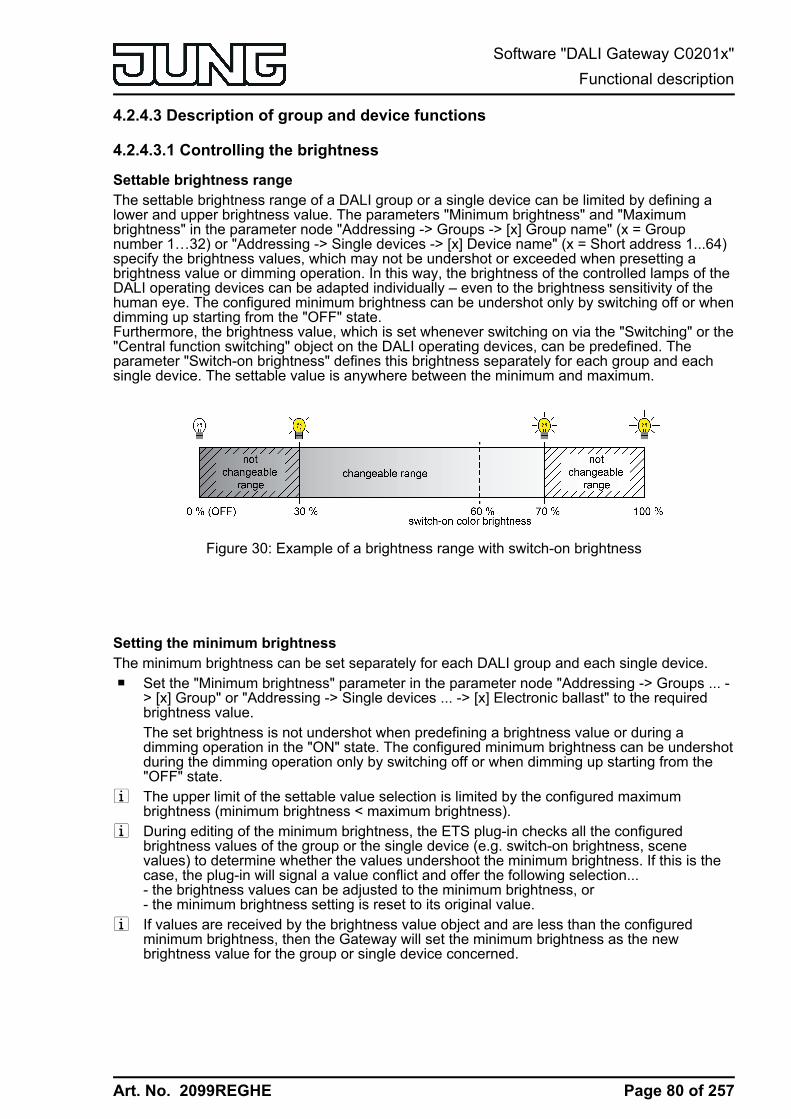
Art. No. 2099REGHE
4.2.4.3 Description of group and device functions
4.2.4.3.1 Controlling the brightness
Settable brightness rangeThe settable brightness range of a DALI group or a single device can be limited by defining alower and upper brightness value. The parameters "Minimum brightness" and "Maximumbrightness" in the parameter node "Addressing -> Groups -> [x] Group name" (x = Groupnumber 1…32) or "Addressing -> Single devices -> [x] Device name" (x = Short address 1...64)specify the brightness values, which may not be undershot or exceeded when presetting abrightness value or dimming operation. In this way, the brightness of the controlled lamps of theDALI operating devices can be adapted individually – even to the brightness sensitivity of thehuman eye. The configured minimum brightness can be undershot only by switching off or whendimming up starting from the "OFF" state.Furthermore, the brightness value, which is set whenever switching on via the "Switching" or the"Central function switching" object on the DALI operating devices, can be predefined. Theparameter "Switch-on brightness" defines this brightness separately for each group and eachsingle device. The settable value is anywhere between the minimum and maximum.
Figure 30: Example of a brightness range with switch-on brightness
Setting the minimum brightnessThe minimum brightness can be set separately for each DALI group and each single device.o Set the "Minimum brightness" parameter in the parameter node "Addressing -> Groups ... -
> [x] Group" or "Addressing -> Single devices ... -> [x] Electronic ballast" to the requiredbrightness value.The set brightness is not undershot when predefining a brightness value or during adimming operation in the "ON" state. The configured minimum brightness can be undershotduring the dimming operation only by switching off or when dimming up starting from the"OFF" state.
i The upper limit of the settable value selection is limited by the configured maximumbrightness (minimum brightness < maximum brightness).
i During editing of the minimum brightness, the ETS plug-in checks all the configuredbrightness values of the group or the single device (e.g. switch-on brightness, scenevalues) to determine whether the values undershoot the minimum brightness. If this is thecase, the plug-in will signal a value conflict and offer the following selection...- the brightness values can be adjusted to the minimum brightness, or- the minimum brightness setting is reset to its original value.
i If values are received by the brightness value object and are less than the configuredminimum brightness, then the Gateway will set the minimum brightness as the newbrightness value for the group or single device concerned.
Page 80 of 257
Software "DALI Gateway C0201x"Functional description
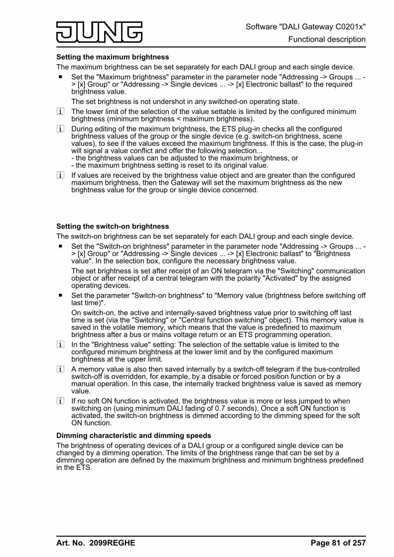
Art. No. 2099REGHE
Setting the maximum brightnessThe maximum brightness can be set separately for each DALI group and each single device.o Set the "Maximum brightness" parameter in the parameter node "Addressing -> Groups ... -
> [x] Group" or "Addressing -> Single devices ... -> [x] Electronic ballast" to the requiredbrightness value.The set brightness is not undershot in any switched-on operating state.
i The lower limit of the selection of the value settable is limited by the configured minimumbrightness (minimum brightness < maximum brightness).
i During editing of the maximum brightness, the ETS plug-in checks all the configuredbrightness values of the group or the single device (e.g. switch-on brightness, scenevalues), to see if the values exceed the maximum brightness. If this is the case, the plug-inwill signal a value conflict and offer the following selection...- the brightness values can be adjusted to the maximum brightness, or- the maximum brightness setting is reset to its original value.
i If values are received by the brightness value object and are greater than the configuredmaximum brightness, then the Gateway will set the maximum brightness as the newbrightness value for the group or single device concerned.
Setting the switch-on brightnessThe switch-on brightness can be set separately for each DALI group and each single device.o Set the "Switch-on brightness" parameter in the parameter node "Addressing -> Groups ... -
> [x] Group" or "Addressing -> Single devices ... -> [x] Electronic ballast" to "Brightnessvalue". In the selection box, configure the necessary brightness value.The set brightness is set after receipt of an ON telegram via the "Switching" communicationobject or after receipt of a central telegram with the polarity "Activated" by the assignedoperating devices.
o Set the parameter "Switch-on brightness" to "Memory value (brightness before switching offlast time)".On switch-on, the active and internally-saved brightness value prior to switching off lasttime is set (via the "Switching" or "Central function switching" object). This memory value issaved in the volatile memory, which means that the value is predefined to maximumbrightness after a bus or mains voltage return or an ETS programming operation.
i In the "Brightness value" setting: The selection of the settable value is limited to theconfigured minimum brightness at the lower limit and by the configured maximumbrightness at the upper limit.
i A memory value is also then saved internally by a switch-off telegram if the bus-controlledswitch-off is overridden, for example, by a disable or forced position function or by amanual operation. In this case, the internally tracked brightness value is saved as memoryvalue.
i If no soft ON function is activated, the brightness value is more or less jumped to whenswitching on (using minimum DALI fading of 0.7 seconds). Once a soft ON function isactivated, the switch-on brightness is dimmed according to the dimming speed for the softON function.
Dimming characteristic and dimming speedsThe brightness of operating devices of a DALI group or a configured single device can bechanged by a dimming operation. The limits of the brightness range that can be set by adimming operation are defined by the maximum brightness and minimum brightness predefinedin the ETS.
Page 81 of 257
Software "DALI Gateway C0201x"Functional description
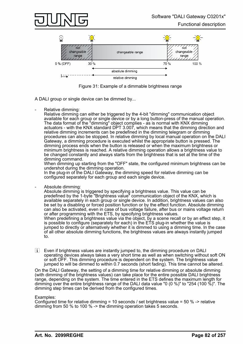
Art. No. 2099REGHE
Figure 31: Example of a dimmable brightness range
A DALI group or single device can be dimmed by...
- Relative dimming:Relative dimming can either be triggered by the 4-bit "dimming" communication objectavailable for each group or single device or by a long button-press of the manual operation.The data format of the "dimming" object complies - as is normal with KNX dimmingactuators - with the KNX standard DPT 3.007, which means that the dimming direction andrelative dimming increments can be predefined in the dimming telegram or dimmingprocedures can also be stopped. In relative dimming by local manual operation on the DALIGateway, a dimming procedure is executed whilst the appropriate button is pressed. Thedimming process ends when the button is released or when the maximum brightness orminimum brightness is reached. A relative dimming operation allows a brightness value tobe changed constantly and always starts from the brightness that is set at the time of thedimming command.When dimming up starting from the "OFF" state, the configured minimum brightness can beundershot during the dimming operation.In the plug-in of the DALI Gateway, the dimming speed for relative dimming can beconfigured separately for each group and each single device.
- Absolute dimming:Absolute dimming is triggered by specifying a brightness value. This value can bepredefined by the 1-byte "Brightness value" communication object of the KNX, which isavailable separately in each group or single device. In addition, brightness values can alsobe set by a disabling or forced position function or by the effect function. Absolute dimmingcan also be activated, even in case of bus voltage failure, after bus or mains voltage returnor after programming with the ETS, by specifying brightness values.When predefining a brightness value via the object, by a scene recall or by an effect step, itis possible to configure (separately for each) in the ETS plug-in whether the value isjumped to directly or alternatively whether it is dimmed to using a dimming time. In the caseof all other absolute dimming functions, the brightness values are always instantly jumpedto.
i Even if brightness values are instantly jumped to, the dimming procedure on DALIoperating devices always takes a very short time as well as when switching without soft ONor soft OFF. This dimming procedure is dependent on the system. The brightness valuejumped to will be dimmed to within 0.7 seconds (short fading). This time cannot be altered.
On the DALI Gateway, the setting of a dimming time for relative dimming or absolute dimming(with dimming of the brightness values) can take place for the entire possible DALI brightnessrange, depending on the system. The time entered in the ETS defines the maximum length fordimming over the entire brightness range of the DALI data value "0 (0 %)" to "254 (100 %)". Thedimming step times can be derived from the configured times.
Examples:Configured time for relative dimming = 10 seconds / set brightness value = 50 % -> relativedimming from 50 % to 100 % -> the dimming operation takes 5 seconds.
Page 82 of 257
Software "DALI Gateway C0201x"Functional description

Art. No. 2099REGHE
Configured time for absolute dimming = 20 seconds / set brightness value = 25 % -> absolutedimming from 25 % to 100 % -> the dimming operation takes 15 seconds. i When the dimming times are configured, the dimming time is always defined for the entire
brightness range (0...100 %). A minimum or maximum brightness configured in the ETSdoes not limit the dimming times, but only specifies the dimmable range.
Setting dimming time for relative dimmingIn the plug-in of the DALI Gateway, the dimming time for relative dimming can be set separatelyfor each group and each single device.o Set the parameter "Time for relative dimming (0...100 %)" in the parameter node
"Addressing -> Groups ... - [x] Group -> Dimming" or "Addressing -> Single devices ... - [x]Electronic ballast -> Dimming" to the required dimming time.
Setting dimming behaviour for absolute dimmingIn the plug-in of the DALI Gateway, the dimming behaviour for absolute dimming can be setseparately for each group and each single device using the "Brightness value" object.o Set the parameter "Dimming behaviour on receipt of a brightness value" in the parameter
node "Addressing -> Groups ... - [x] Group -> Dimming" or "Addressing -> Single devices ...- [x] Electronic ballast -> Dimming" to "Dim to".Once a new brightness value is received, it is set by means of the calculated dimmingincrement time for absolute dimming.
o Set the parameter "dimming behaviour after receipt of a brightness value" to "jump to".As soon as a new brightness value is received it will be instantly jumped to.
i Brightness values can also be set by a disabling or forced position function. Absolutedimming can also be activated, even in case of bus voltage failure, after bus or mainsvoltage return or after programming with the ETS, by specifying brightness values. In thecase of these absolute dimming functions, the brightness values are always instantlyjumped to. During a scene or effect recall, the dimming behaviour can be configuredseparately.
Setting dimming time for absolute dimmingIn the plug-in of the DALI Gateway, the dimming time for absolute dimming can be setseparately for each group and each single device using the "Brightness value" object.The dimming behaviour must be configured as "Dim to".o Set the parameter "Time for absolute dimming (0...100 %)" in the parameter node
"Addressing -> Groups ... - [x] Group -> Dimming" or "Addressing -> Single devices ... - [x]Electronic ballast -> Dimming" to the required dimming time.
Dimming characteristicThe DALI Gateway converts KNX brightness values to DALI brightness values according toDPT 5.001 and brightness values that were configured in the ETS. On the DALI page, thebrightness commands are transmitted in an 8-bit data value from the Gateway to the operatingdevices. This data value according to IEC 62386-102 is referred to as "Arc Power Level (APL)"in the DALI specification. The ideally dimmable brightness range on the DALI page is
Page 83 of 257
Software "DALI Gateway C0201x"Functional description
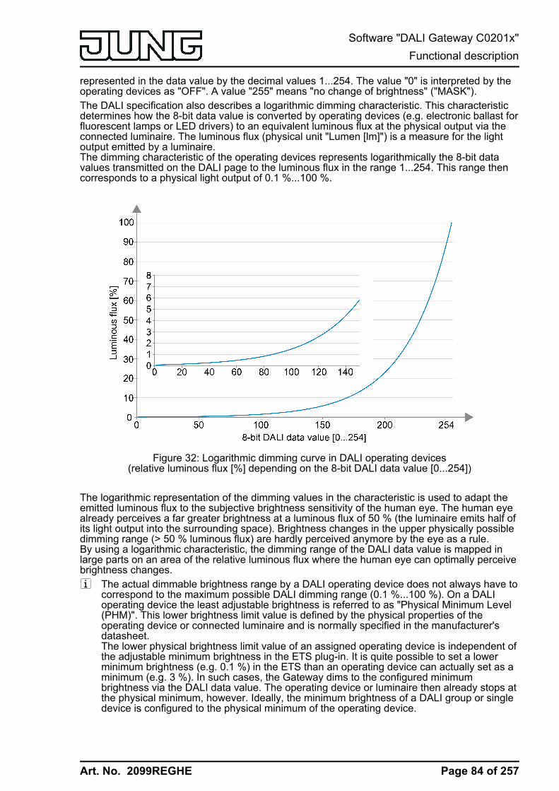
Art. No. 2099REGHE
represented in the data value by the decimal values 1...254. The value "0" is interpreted by theoperating devices as "OFF". A value "255" means "no change of brightness" ("MASK").The DALI specification also describes a logarithmic dimming characteristic. This characteristicdetermines how the 8-bit data value is converted by operating devices (e.g. electronic ballast forfluorescent lamps or LED drivers) to an equivalent luminous flux at the physical output via theconnected luminaire. The luminous flux (physical unit "Lumen [lm]") is a measure for the lightoutput emitted by a luminaire.The dimming characteristic of the operating devices represents logarithmically the 8-bit datavalues transmitted on the DALI page to the luminous flux in the range 1...254. This range thencorresponds to a physical light output of 0.1 %...100 %.
Figure 32: Logarithmic dimming curve in DALI operating devices(relative luminous flux [%] depending on the 8-bit DALI data value [0...254])
The logarithmic representation of the dimming values in the characteristic is used to adapt theemitted luminous flux to the subjective brightness sensitivity of the human eye. The human eyealready perceives a far greater brightness at a luminous flux of 50 % (the luminaire emits half ofits light output into the surrounding space). Brightness changes in the upper physically possibledimming range (> 50 % luminous flux) are hardly perceived anymore by the eye as a rule.By using a logarithmic characteristic, the dimming range of the DALI data value is mapped inlarge parts on an area of the relative luminous flux where the human eye can optimally perceivebrightness changes.i The actual dimmable brightness range by a DALI operating device does not always have to
correspond to the maximum possible DALI dimming range (0.1 %...100 %). On a DALIoperating device the least adjustable brightness is referred to as "Physical Minimum Level(PHM)". This lower brightness limit value is defined by the physical properties of theoperating device or connected luminaire and is normally specified in the manufacturer'sdatasheet.The lower physical brightness limit value of an assigned operating device is independent ofthe adjustable minimum brightness in the ETS plug-in. It is quite possible to set a lowerminimum brightness (e.g. 0.1 %) in the ETS than an operating device can actually set as aminimum (e.g. 3 %). In such cases, the Gateway dims to the configured minimumbrightness via the DALI data value. The operating device or luminaire then already stops atthe physical minimum, however. Ideally, the minimum brightness of a DALI group or singledevice is configured to the physical minimum of the operating device.
Page 84 of 257
Software "DALI Gateway C0201x"Functional description

Art. No. 2099REGHE
i A logarithmic dimming characteristic is standard in DALI operating devices and cannormally be found in the delivery state. However, there are some operating devices, inwhich the characteristic curve can be adjusted - often by manufacturer-specific softwaretools. As a rule, it is possible to switch between a linear characteristic and a logarithmiccharacteristic.Such operating devices must always be set to a logarithmic characteristic in conjunctionwith the KNX DALI Gateway. Otherwise, the mechanism of the configurable characteristicsof the DALI Gateway is incorrect!
When dimming, the logarithmic characteristic curve provided for DALI is not ideal for everycontrol task. For this reason, the KNX DALI Gateway offers the possibility of influencing theDALI dimming characteristic without having to intervene in the operating devices. For thispurpose, for each DALI group and single device in the ETS plug-in in the parameter node"Addressing -> Groups ... - [x] Group -> Dimming" or "Addressing -> Single devices ... - [x]Electronic ballast -> Dimming" the parameter "DALI dimming characteristic" is available.
- Linear DALI dimming characteristic:
In this setting, the Gateway linearises the DALI dimming characteristic by converting allbrightness values, which are received from the KNX and configured in the ETS,appropriately into DALI data values. Thus, the KNX brightness values form linearly on theluminous flux emitted by the DALI luminaire. The Gateway itself does not dim linearly in thissetting. A linear dimming sequence of the relative luminous flux first results at the physicaloutput of an operating device through the combination of the non-linear conversion of theGateway and the logarithmic characteristic of the operating devices.Feedbacks of the brightness value to the KNX are also adjusted through conversion. Onaccount of the internal calculation process, there may be slight deviations between thespecified and fed back brightness value (e.g. specification = 50 % -> Feedback = 49 %).
Example of brightness change:KNX brightness: 50 % -> DALI data value (APL): 229 -> Luminous flux: approx. 50 % ->The human eye already perceives an intensive brightness.KNX brightness: 75 % -> DALI data value (APL): 243 -> luminous flux: approx. 75 % -> Thehuman eye hardly perceives the brightness difference between the previous dimmingsetting anymore. The dimming operation appears unsteady.
Page 85 of 257
Software "DALI Gateway C0201x"Functional description

Art. No. 2099REGHE
Figure 33: Linear DALI dimming characteristic(relative luminous flux [%] depending on the 8-bit KNX data value [0...255])
KNX brightnessvalue
KNX brightness value[%]
DALI data value(APL)
Luminous flux[%]
0 0 0 0
1 0.4 27 0.2
10 4 136 4
50 20 194 19
80 32 212 32
100 40 220 40
125 50 228 49
150 60 235 60
175 70 240 68
200 80 245 78
225 90 249 87
255 100 254 100
Transmission of data values with a linear DALI dimming characteristic
Page 86 of 257
Software "DALI Gateway C0201x"Functional description

Art. No. 2099REGHE
i Advantages of a linear DALI dimming characteristic:Adjustment to existing KNX actuators possible. KNX dimming actuators or 1-10-V controlunits normally form brightness values linearly in a physical output signal by the "Scaling"(DPT 5.001 / 0...255 -> 0.4 %...100 %) defined according to the KNX specification. If aDALI system with such KNX actuators is combined in an installation, it is normallynecessary to set a linear dimming characteristic in the DALI Gateway in order to adapt thedimming behaviour to the other actuators. Otherwise, the luminaires will dim to a differentbrightness with identical KNX data values.A linear dimming characteristic also has a positive effect on a multichannel RGB colourcontrol, especially during dynamic colour changes (e.g. control of 3 different DALI channelsfor RGB colour mixing). By converting the KNX data values to a linear luminous flux foreach primary colour, colours can be mixed reliably in a wide spectrum by the luminaire.In the case of operating devices that have a high physical minimum brightness (> 3 %) andthus a limited luminous flux range, a linear characteristic allows the possible KNXbrightness range(0.4 %...100 %) to be utilised usefully in the lower dimming range by the increased DALIdata values.
i Disadvantages of a linear DALI dimming characteristic:Dimming operations are not adjusted to the brightness perception of the human eye. Thismeans that the dimming behaviour for mere brightness control is perceived as uneven dueto the logarithmic human perception.High number of levels in the lower dimming range.
- Logarithmic DALI dimming characteristic:
With this setting, the Gateway forwards KNX brightness values to the DALI page virtuallyunprocessed. Merely a smoothing of the data values in the lower dimming range takesplace. A logarithmic dimming sequence of the relative luminous flux results at the physicaloutput of an operating device through the combination of forwarding the value of theGateway and the logarithmic characteristic of the operating devices.Feedbacks of the effective DALI brightness value to the KNX is also possible in this case.Owing to the finely adjustable level in the lower dimming range of a logarithmic DALIcharacteristic, KNX brightness values of up to approx. 10 % are reported as a brightnessvalue 0.4 %. Predefined KNX brightness values up to approx. 23 % are displayed in thefeedback as brightness value 11 % and KNX brightness values up to approx. 33 % aredisplayed as brightness value 24 %. The feedback occurs constantly from approx. 34 %KNX brightness.
Example of brightness change:KNX brightness: 50 % -> DALI data value (APL): 128 -> Luminous flux: approx. 3 % -> Thehuman eye subjectively perceives about half of the luminaire brightness.KNX brightness: 75 % -> DALI data value (APL): 191 -> Luminous flux: approx. 18 % ->The human eye clearly perceives a brightness difference between the previous dimmingsetting. The dimming operation is constantly effective.
Page 87 of 257
Software "DALI Gateway C0201x"Functional description

Art. No. 2099REGHE
Figure 34: Logarithmic DALI dimming characteristic(relative luminous flux [%] depending on the 8-bit KNX data value [0...255])
KNX brightnessvalue
KNX brightness value[%]
DALI data value(APL)
Luminous flux[%]
0 0 0 0
1 0.4 1 0.1
10 4 1 0.1
50 20 27 0.2
80 32 60 0.5
100 40 100 1.5
125 50 125 3
150 60 150 5.8
175 70 175 12
200 80 200 23
225 90 225 45
255 100 254 100
Transmission of data values with a logarithmic DALI dimming characteristic
i Advantages of a logarithmic DALI dimming characteristic:Ideal for pure brightness controls. Adjustment to the brightness perception of the humaneye. As a result, brightness changes are perceived evenly in the entire dimming range.Fine number of levels in the lower dimming range.
Page 88 of 257
Software "DALI Gateway C0201x"Functional description
Art. No. 2099REGHE
i Disadvantages of a logarithmic DALI dimming characteristic:Difficult adjustment up to no adjustment at all on other KNX actuators that only dim linearly.Poor sliding progression when mixing colours via separate DALI channels.In the case of operating devices that have a high physical minimum brightness (> 3 %) andthus a limited luminous flux range, the lower KNX dimming range (0.4 %...50 %) cannot beutilised.
Page 89 of 257
Software "DALI Gateway C0201x"Functional description

Art. No. 2099REGHE
4.2.4.3.2 Controlling the colour temperature
Settable colour temperature rangeWhen activating DALI operating devices that support the device type"Tunable White" (DT8 - TW), the colour temperature of the connected luminaire can bechanged. The settable colour temperature range of a DALI group or single device can be limitedby defining a lower and upper colour temperature value. The parameters "Minimum colourtemperature" and "Maximum colour temperature" in the parameter node "Addressing -> Groups-> [x] Group name -> Tunable white function" (x = Group number 1…32) or "Addressing ->Single devices -> [x] Device name -> Tunable white function" (x = Short address 1...64) specifythe colour temperature values, which may not be undershot or exceeded when the Gateway isin a switched-on operating state. In this way, the colour temperature of the controlled luminairesof the DALI operating devices can be limited individually and adapted to the respectiveapplication.Furthermore, the colour temperature value, which is set whenever switching on via the"Switching" or the "Central function switching" object on the DALI operating devices, can bepredefined. The parameter "Colour temperature after switching on" defines this colourtemperature value separately for each group and each single device. The settable value isanywhere between the minimum and maximum colour temperature.
Figure 35: Example of a configured colour temperature range with switch-on colour temperature
i DALI lights that can change the colour temperature are generally fitted with two differentluminaires for warm white and cold white light. The luminous flux of both luminaires can bevaried independently and thus the colour temperature can be changed in the specifiedrange by different activation via the upstream DALI operating device(e.g. DALI DT8 LED driver). In the lower colour temperature range, only the warm whiteluminaire is usually switched on. In the upper colour temperature range, only the cold whiteluminaire is switched on. A DALI operating device according to device type 8 essentiallychanges the proportional luminous flux of the luminaire while maintaining the total luminousflux provided, which is specified via the brightness of the DALI group or single device.During a dimming operation of the colour temperature, it can happen that the operatingdevices switch the luminaire on or off if required. This can lead to switching operations inthe transition ranges, which cause the dimming operations to briefly appear unsteady.
Setting minimum colour temperatureThe minimum colour temperature can be set separately for each DALI group and each singledevice.o Set the parameter "Minimum colour temperature" in the parameter node "Addressing ->
Groups -> [x] Group name -> Tunable white function" or "Addressing -> Single devices ->[x] Device name -> Tunable white function" to the required colour temperature.The set colour temperature is not undershot in any operating state.
i The upper limit of the selection of the value settable here is limited by the configuredmaximum colour temperature (minimum colour temperature < maximum colourtemperature).
Page 90 of 257
Software "DALI Gateway C0201x"Functional description

Art. No. 2099REGHE
i During editing of the minimum colour temperature, the ETS plug-in checks all configuredcolour temperature values of the group or the single device (e.g. switch-on colourtemperature, scene values) to determine whether the values undershoot the minimumcolour temperature. If this is the case, the plug-in will signal a value conflict and offer thefollowing selection...- the colour temperature values can be adjusted to the minimum colour temperature, or- the minimum colour temperature setting is reset to its original value.
i If values are received by the "Absolute colour temperature" object and are less than theconfigured minimum colour temperature, then the Gateway will set the minimum colourtemperature as the new colour temperature value for the group or single device concerned.In this case, the 1-bit "Invalid colour temperature" feedback can be generated as an option.
Setting the maximum colour temperatureThe maximum colour temperature can be set separately for each DALI group and each singledevice.o Set the parameter "Maximum colour temperature" in the parameter node "Addressing ->
Groups -> [x] Group name -> Tunable white function" or "Addressing -> Single devices ->[x] Device name -> Tunable white function" to the required colour temperature value.The set brightness is not undershot in any switched-on operating state.
i The lower limit of the selection of the value settable here is limited by the configuredminimum colour temperature (minimum colour temperature < maximum colourtemperature).
i During editing of the maximum colour temperature, the ETS plug-in checks all theconfigured colour temperature values of the group or the single device (e.g. switch-oncolour temperature, scene values) to determine whether the values exceed the maximumcolour temperature. If this is the case, the plug-in will signal a value conflict and offer thefollowing selection...- the colour temperature values can be adjusted to the maximum colour temperature, or- the maximum colour temperature setting is reset to its original value.
i If values are received by the "Absolute colour temperature" object and are greater than theconfigured maximum colour temperature, then the Gateway will set the maximum colourtemperature as the new colour temperature value for the group or single device concerned.In this case, the 1-bit "Invalid colour temperature" feedback can be generated as an option.
Setting the switch-on colour temperatureThe switch-on colour temperature can be set separately for each DALI group and each singledevice.o Set the parameter "Colour temperature after switching on" in the parameter node
"Addressing -> Groups -> [x] Group name -> Tunable white function" or "Addressing ->Single devices -> [x] Device name -> Tunable white function" to "Set colour temperaturevalue". In the selection box, configure the necessary colour temperature value.The set colour temperature is set after receipt of an ON telegram via the "Switching"communication object or after receipt of a central telegram with the polarity "activated".
o Set the parameter "Colour temperature after switching on" to "Memory value (colourtemperature before switching off last time)".On switching on, the active and internally saved colour temperature value prior to switchingoff last time is set (via the "Switching" or "Central function switching" object). This memoryvalue is saved in the volatile memory, which means that after a device reset (mains voltagereturn or an ETS programming operation), the value is predefined to maximum colourtemperature.
o Set the parameter "Colour temperature after switching on" to "tracked colour temperaturevalue".
Page 91 of 257
Software "DALI Gateway C0201x"Functional description

Art. No. 2099REGHE
On switching on, the internally tracked colour temperature most recently specified and inthe "OFF" state is preset. The tracked colour temperature value is not influenced by anETS programming operation or by a bus voltage failure ("no change"). When the bus/mainsvoltage returns, the colour temperature active most recently before the bus/mains voltagefailure is restored. Hence, this colour temperature is taken into account as a colourtemperature value to be tracked when switching on.
i In the "Set colour temperature value" setting: The lower limit of the selection of the valuethat can be set here is limited by the configured minimum colour temperature and the upperlimit by the configured maximum colour temperature.
i A memory value is also then saved internally by a switch-off telegram if the bus-controlledswitch-off is overridden, for example, by a disable or forced position function or by amanual operation. In this case, the internally tracked colour temperature value is saved asmemory value.
i The colour temperature to be set by switching on is either dimmed in the configureddimming time or is jumped to directly depending on the configured dimming behaviour(absolute dimming). The dimming characteristic for colour temperature changes is alwayslinear.
i A switched-off DALI group or single device can also be switched on by the receipt of anabsolute colour temperature value or by relative dimming (configurable functions) ifnecessary. In this case, the switch-on colour temperature is not evaluated. The Gatewaythen activates on switching on the colour temperature, which was set directly by theabsolute colour temperature value or by the relative dimming operation.
Dimming characteristic and dimming speedsWhen activating DALI operating devices that support the device type "Tunable White" (DT8 -TW), the colour temperature can be changed by a relative or absolute dimming operation. Thelimits of the colour temperature range adjustable by a dimming operation is defined by theminimum and maximum colour temperature predefined in the ETS.
Figure 36: Example of a dimmable colour temperature range
A DALI group or single device can be dimmed by...
Page 92 of 257
Software "DALI Gateway C0201x"Functional description

Art. No. 2099REGHE
- Relative dimming:Relative dimming of the colour temperature can be triggered by the 4-bit "Relative colourtemperature" communication object available for each group or single device. The dataformat of the "dimming" object - as well as with relative dimming of the brightness -complies with the KNX standard DPT 3.007, which means that the dimming direction andrelative dimming increments can be predefined in the dimming telegram or dimmingprocedures can also be stopped. A relative dimming operation allows a colour temperaturevalue to be changed constantly and always starts from the colour temperature that is set atthe time of the dimming command.In the plug-in of the DALI Gateway, the dimming speed for relative dimming of the colourtemperature can be configured separately for each group and each single device andindependent of the dimming speed for a brightness change.A relative dimming telegram for controlling the colour temperature can also switch on agroup or single device in the "OFF" state. In some applications, it may be necessary,however, for a switched off group or switched off device to still remain off until a relativedimming telegram of the colour temperature is received. This is interesting when using lightscenes, for instance: Several DALI groups are set to a defined colour temperature via alight scene. Other groups are switched off by the scene. Only the colour temperature ofchannels not switched off by the scene recall should be changed by dimming upafterwards. Here, it is necessary for groups or single devices not to respond to a relativedimming operation of the colour temperature and thus not to switch on. The parameter"Behaviour when OFF by relative dimming of the colour temperature" defines whether ornot a DALI group or single device in the "OFF" state switches on via a relative dimmingtelegram of the colour temperature or remains switched off and only tracks the dimmingoperation internally.
- Absolute dimming:Absolute dimming is triggered by specifying a colour temperature value. This value can bepredefined by the 2-byte "Absolute colour temperature (K)" communication objectaccording to KNX DPT 7.600 of the KNX, which is available separately in each group orsingle device. In addition, colour temperature values can also be set by the scene functionor by the effect function.When predefining a colour temperature value via the object, by a scene recall or by aneffect step, it is possible to configure (separately for each) in the ETS plug-in whether thevalue is jumped to directly or alternatively whether it is dimmed to using a dimming time(Fading Time).Just as with relative dimming, an absolute dimming telegram for controlling the colourtemperature can also switch on a group or single device in the "OFF" state. Here too, itmay be necessary in some applications for a switched off group or switched off device tostill remain off if a new colour temperature value is specified absolutely. The parameter"Behaviour when OFF by absolute dimming of the colour temperature" defines whether ornot a DALI group or single device in the "OFF" state switches on via a new absolute 2-bytedimming telegram of the colour temperature or remains switched off and only tracks thecolour value internally.
On the DALI Gateway, it is possible that the setting of a dimming time for relative dimming orabsolute dimming (with dimming of the colour temperature values) can take place for the DALIGateway in the range minimum colour temperature to maximum colour temperature. Thedimming step times can be derived from the configured times.i The dimming characteristic for colour temperature changes is always linear.i It is possible via the 1-bit "Absolute colour temperature (K)" feedback object to optionally
display whether a colour temperature specified externally via the "Absolute colourtemperature (K)" is valid. This is the case, if the specified colour temperature violates theset limits of the minimum and maximum colour temperature.
i Relative dimming of the colour temperature cannot be triggered by manual operationdirectly on the device.
Page 93 of 257
Software "DALI Gateway C0201x"Functional description
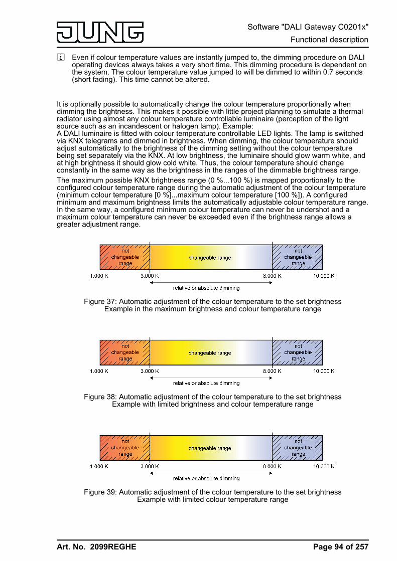
Art. No. 2099REGHE
i Even if colour temperature values are instantly jumped to, the dimming procedure on DALIoperating devices always takes a very short time. This dimming procedure is dependent onthe system. The colour temperature value jumped to will be dimmed to within 0.7 seconds(short fading). This time cannot be altered.
It is optionally possible to automatically change the colour temperature proportionally whendimming the brightness. This makes it possible with little project planning to simulate a thermalradiator using almost any colour temperature controllable luminaire (perception of the lightsource such as an incandescent or halogen lamp). Example:A DALI luminaire is fitted with colour temperature controllable LED lights. The lamp is switchedvia KNX telegrams and dimmed in brightness. When dimming, the colour temperature shouldadjust automatically to the brightness of the dimming setting without the colour temperaturebeing set separately via the KNX. At low brightness, the luminaire should glow warm white, andat high brightness it should glow cold white. Thus, the colour temperature should changeconstantly in the same way as the brightness in the ranges of the dimmable brightness range.The maximum possible KNX brightness range (0 %...100 %) is mapped proportionally to theconfigured colour temperature range during the automatic adjustment of the colour temperature(minimum colour temperature [0 %]...maximum colour temperature [100 %]). A configuredminimum and maximum brightness limits the automatically adjustable colour temperature range.In the same way, a configured minimum colour temperature can never be undershot and amaximum colour temperature can never be exceeded even if the brightness range allows agreater adjustment range.
Figure 37: Automatic adjustment of the colour temperature to the set brightnessExample in the maximum brightness and colour temperature range
Figure 38: Automatic adjustment of the colour temperature to the set brightnessExample with limited brightness and colour temperature range
Figure 39: Automatic adjustment of the colour temperature to the set brightnessExample with limited colour temperature range
Page 94 of 257
Software "DALI Gateway C0201x"Functional description
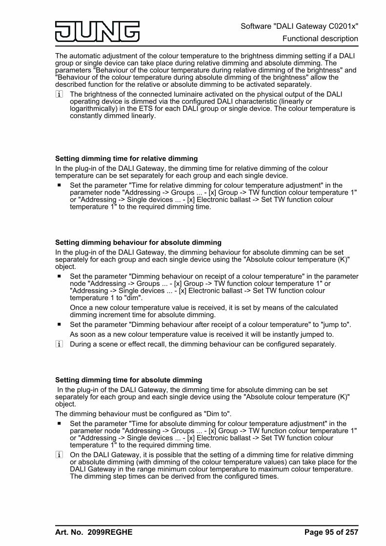
Art. No. 2099REGHE
The automatic adjustment of the colour temperature to the brightness dimming setting if a DALIgroup or single device can take place during relative dimming and absolute dimming. Theparameters "Behaviour of the colour temperature during relative dimming of the brightness" and"Behaviour of the colour temperature during absolute dimming of the brightness" allow thedescribed function for the relative or absolute dimming to be activated separately.i The brightness of the connected luminaire activated on the physical output of the DALI
operating device is dimmed via the configured DALI characteristic (linearly orlogarithmically) in the ETS for each DALI group or single device. The colour temperature isconstantly dimmed linearly.
Setting dimming time for relative dimmingIn the plug-in of the DALI Gateway, the dimming time for relative dimming of the colourtemperature can be set separately for each group and each single device.o Set the parameter "Time for relative dimming for colour temperature adjustment" in the
parameter node "Addressing -> Groups ... - [x] Group -> TW function colour temperature 1"or "Addressing -> Single devices ... - [x] Electronic ballast -> Set TW function colourtemperature 1" to the required dimming time.
Setting dimming behaviour for absolute dimmingIn the plug-in of the DALI Gateway, the dimming behaviour for absolute dimming can be setseparately for each group and each single device using the "Absolute colour temperature (K)"object.o Set the parameter "Dimming behaviour on receipt of a colour temperature" in the parameter
node "Addressing -> Groups ... - [x] Group -> TW function colour temperature 1" or"Addressing -> Single devices ... - [x] Electronic ballast -> Set TW function colourtemperature 1 to "dim".Once a new colour temperature value is received, it is set by means of the calculateddimming increment time for absolute dimming.
o Set the parameter "Dimming behaviour after receipt of a colour temperature" to "jump to".As soon as a new colour temperature value is received it will be instantly jumped to.
i During a scene or effect recall, the dimming behaviour can be configured separately.
Setting dimming time for absolute dimming In the plug-in of the DALI Gateway, the dimming time for absolute dimming can be setseparately for each group and each single device using the "Absolute colour temperature (K)"object.The dimming behaviour must be configured as "Dim to".o Set the parameter "Time for absolute dimming for colour temperature adjustment" in the
parameter node "Addressing -> Groups ... - [x] Group -> TW function colour temperature 1"or "Addressing -> Single devices ... - [x] Electronic ballast -> Set TW function colourtemperature 1" to the required dimming time.
i On the DALI Gateway, it is possible that the setting of a dimming time for relative dimmingor absolute dimming (with dimming of the colour temperature values) can take place for theDALI Gateway in the range minimum colour temperature to maximum colour temperature.The dimming step times can be derived from the configured times.
Page 95 of 257
Software "DALI Gateway C0201x"Functional description

Art. No. 2099REGHE
Setting dimming behaviour in OFF state for relative dimmingA relative dimming telegram for controlling the colour temperature can also switch on a group orsingle device in the "OFF" state. In the plug-in of the DALI Gateway, the behaviour in the "OFF"state when receiving a relative dimming telegram can be set separately for each group andeach single device by the parameter "Behaviour when OFF by relative dimming of the colourtemperature".o Set the parameter to "Colour temp. value change switches ON (standard)".
The DALI group or the single device in the "OFF" state is switched to the switch-onbrightness by a relative dimming telegram of the colour temperature telegram. Thedimming operation for the colour temperature starts at the colour temperature value mostrecently set by the Gateway or which was tracked in the "OFF" state. The relative dimmingtelegram that leads to switching on, specifies the dimming direction and dimmingincrement. The dimming operation stops after reaching the specified colour temperature.
i After an ETS programming operation, the colour temperature value, at which the dimmingoperation is started for relative dimming after the "OFF" state, is permanently set to themean value of the configured colour temperature range: colour temperature start dim =((colour temperature max - colour temperature min) : 2) + colour temperature min.
o Set the parameter to "Colour temp. value change is ignored".The DALI group or the single device in the "OFF" state is not switched on by the relativedimming telegram. The group or single device remains switched off and only tracks thedimming operation internally based on the last valid colour temperature currently set.
Setting dimming behaviour in OFF state for absolute dimming An absolute 2-byte colour temperature telegram can also switch on a group or single device inthe "OFF" state. In the plug-in of the DALI Gateway, the behaviour in the "OFF" state whenreceiving an absolute colour temperature telegram can be set separately for each group andeach single device by the parameter "Behaviour when OFF by absolute dimming of the colourtemperature".o Set the parameter to "Colour temp. value change switches ON (standard)".
The DALI group or the single device in the "OFF" state is switched to switch-on brightnessby an absolute colour temperature telegram. If the dimming behaviour of the absolutecolour temperature is configured to "jump to", the intended colour temperature value ispreset. If the dimming behaviour is configured to "dim to", the dimming operation starts atthe colour temperature value most recently set by the Gateway or which was tracked in the"OFF" state. The dimming operation is executed according to the set dimming time. Thedimming operation stops after reaching the specified colour temperature.
o Set the parameter to "Colour temp. value change is ignored".The DALI group or the single device in the "OFF" state is not switched by the absolutecolour temperature telegram. The group or the single device remains switched off and onlytracks the colour temperature value internally.
Setting the behaviour of the colour temperature during dimming of the brightness It is optionally possible to automatically change the colour temperature proportionally whendimming the brightness. This makes it possible with little project planning to simulate a thermalradiator using almost any colour temperature controllable luminaire (perception of the lightsource such as an incandescent or halogen lamp). In the plug-in of the DALI Gateway, thebehaviour of the colour temperature can be set separately by means of parameters for eachgroup and each single device for this application during dimming of the brightness separately forthe relative or absolute dimming.
Page 96 of 257
Software "DALI Gateway C0201x"Functional description

Art. No. 2099REGHE
o Set the "Behaviour of the colour temperature during relative dimming of the brightness" to"no change of colour temperature".The relative dimming of the brightness via a 4-bit dimming telegram has no effect on thecolour temperature of the group or single device. The colour temperature can only becontrolled separately.
o Set the "Behaviour of the colour temperature during relative dimming of the brightness" to"Colour temperature proportional to brightness".During relative dimming of the brightness via a 4-bit dimming telegram, the colourtemperature of the group or single device is also changed proportionally. The colourtemperature becomes warmer when dimming down. The colour temperature becomescolder when dimming up.The colour temperature can also be controlled separately.
o Set the parameter "Behaviour of the colour temperature during absolute dimming of thebrightness" to "no change of colour temperature".The absolute dimming of the brightness via a 1-byte brightness value has no effect on thecolour temperature of the group or single device. The colour temperature can only becontrolled separately.
o Set the parameter "Behaviour of the colour temperature during absolute dimming of thebrightness" to "Colour temperature proportional to brightness".During absolute dimming of the brightness via a 1-byte brightness value, the colourtemperature of the group or single device is also changed proportionally. The colourtemperature becomes warmer when dimming down. The colour temperature becomescolder when dimming up.The colour temperature can also be controlled separately.
Page 97 of 257
Software "DALI Gateway C0201x"Functional description
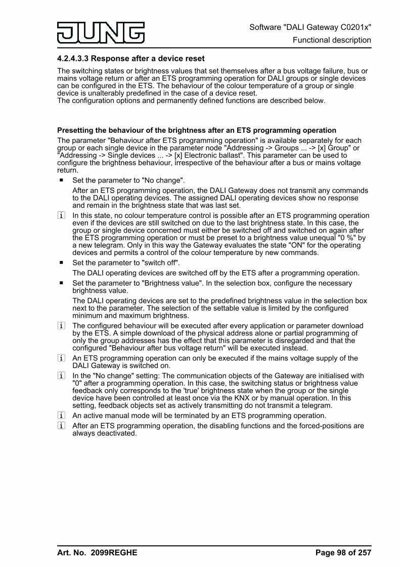
Art. No. 2099REGHE
4.2.4.3.3 Response after a device resetThe switching states or brightness values that set themselves after a bus voltage failure, bus ormains voltage return or after an ETS programming operation for DALI groups or single devicescan be configured in the ETS. The behaviour of the colour temperature of a group or singledevice is unalterably predefined in the case of a device reset.The configuration options and permanently defined functions are described below.
Presetting the behaviour of the brightness after an ETS programming operationThe parameter "Behaviour after ETS programming operation" is available separately for eachgroup or each single device in the parameter node "Addressing -> Groups ... -> [x] Group" or"Addressing -> Single devices ... -> [x] Electronic ballast". This parameter can be used toconfigure the brightness behaviour, irrespective of the behaviour after a bus or mains voltagereturn.o Set the parameter to "No change".
After an ETS programming operation, the DALI Gateway does not transmit any commandsto the DALI operating devices. The assigned DALI operating devices show no responseand remain in the brightness state that was last set.
i In this state, no colour temperature control is possible after an ETS programming operationeven if the devices are still switched on due to the last brightness state. In this case, thegroup or single device concerned must either be switched off and switched on again afterthe ETS programming operation or must be preset to a brightness value unequal "0 %" bya new telegram. Only in this way the Gateway evaluates the state "ON" for the operatingdevices and permits a control of the colour temperature by new commands.
o Set the parameter to "switch off".The DALI operating devices are switched off by the ETS after a programming operation.
o Set the parameter to "Brightness value". In the selection box, configure the necessarybrightness value.The DALI operating devices are set to the predefined brightness value in the selection boxnext to the parameter. The selection of the settable value is limited by the configuredminimum and maximum brightness.
i The configured behaviour will be executed after every application or parameter downloadby the ETS. A simple download of the physical address alone or partial programming ofonly the group addresses has the effect that this parameter is disregarded and that theconfigured "Behaviour after bus voltage return" will be executed instead.
i An ETS programming operation can only be executed if the mains voltage supply of theDALI Gateway is switched on.
i In the "No change" setting: The communication objects of the Gateway are initialised with"0" after a programming operation. In this case, the switching status or brightness valuefeedback only corresponds to the 'true' brightness state when the group or the singledevice have been controlled at least once via the KNX or by manual operation. In thissetting, feedback objects set as actively transmitting do not transmit a telegram.
i An active manual mode will be terminated by an ETS programming operation.i After an ETS programming operation, the disabling functions and the forced-positions are
always deactivated.
Page 98 of 257
Software "DALI Gateway C0201x"Functional description

Art. No. 2099REGHE
i After an ETS programming operation, the DALI Gateway initialises itself and configures theconnected operating devices with relevant data via the DALI cable (e.g. minimumbrightness, maximum brightness, power-on level, system failure level). For this reason, theentire DALI system should ideally be connected and completely ready for operation so thatall operating devices apply configuration changes. After each DALI commissioning withchanges (fully or partially), the application program must be reloaded into the Gatewayusing the ETS. When doing so, it must be ensured that at least the newly added operatingdevices or devices, in which the configuration was changed in the ETS, are ready foroperation after the ETS programming operation during the commissioning.If there is an error on the DALI cable (e.g. short-circuit, cable break) during the initialisationof the operating devices, then the DALI configuration cannot be executed. The error mustthen be eliminated and ETS programming restarted. During the configuration operationafter an ETS programming operation, "- -" is displayed in the 7-segment display on the frontpanel of the device.
i If KNX telegrams for groups or single devices are received during Gateway initialisation,then the device will perform the most recently specified command and not the configuredbehaviour after an ETS programming operation.
Setting the behaviour of the brightness in case of bus voltage failureThe parameter "Behaviour on bus voltage failure" is available separately for each group or eachsingle device in the parameter node "Addressing -> Groups ... -> [x] Group" or "Addressing ->Single devices ... -> [x] Electronic ballast".o Set the parameter to "No change".
In the case of a bus voltage failure, the DALI Gateway does not transmit any commands tothe DALI operating devices. The assigned DALI operating devices show no response andremain in the brightness state that was last set.
o Set the parameter to "switch off".The DALI operating devices are switched off via the DALI cable in the case of a busvoltage failure if the mains voltage supply of the Gateway is still switched on.
o Set the parameter to "Brightness value". In the selection box, configure the necessarybrightness value.The DALI operating devices are set to the predefined brightness value via the DALI cablein the selection box next to the parameter. The selection of the settable value is limited bythe configured minimum and maximum brightness.
i If there is a voltage failure on the DALI cable (e.g. due to short-circuit, cable break, mainsvoltage failure on on DALI Gateway), then the assigned DALI operating devices will alsoshow the configured behaviour when the bus voltage fails. This is guaranteed because theparameter setting in the DALI operating devices is applied as the "System Failure Level" forthe brightness after an ETS programming operation.Exception: Optionally, the system failure level, regardless of the behaviour in case of busvoltage return, can be set on centrally supplied emergency lights to a separate brightnessvalue for emergency operation. In these cases, it is not the configuration for the "Behaviouron bus voltage failure" which is applied as the System Failure Level, but the brightnessdefined for emergency operation.
i In the event of a bus failure or mains voltage failure, the current states of the forcedpositions are also saved so that they can be tracked in the event of bus or mains voltagereturn if necessary (depending on the configuration of the forced positions).
i Active disabling functions or forced position functions are always cancelled by a busvoltage failure and are subsequently inactive in the connection.
Page 99 of 257
Software "DALI Gateway C0201x"Functional description

Art. No. 2099REGHE
Setting the behaviour of the brightness after bus voltage returnThe parameter "Behaviour after bus voltage return" is available separately for each group oreach single device in the parameter node "Addressing -> Groups ... -> [x] Group" or"Addressing -> Single devices ... -> [x] Electronic ballast". The parameter also defines thebehaviour of the DALI Gateway after mains voltage return.o Set the parameter to "No change".
After bus or mains voltage return, the DALI Gateway does not transmit any commands tothe DALI operating devices. The assigned DALI operating devices show no response andremain in the brightness state that was last set (also see the note on "Power-On Level"further below).
i In this state, no colour temperature control is possible after bus or mains voltage returneven if the devices are still switched on due to the last brightness state. In this case, thegroup or single device concerned must either be switched off and switched on again afterbus or mains voltage return or must be preset to a brightness value unequal "0 %" by anew telegram. Only in this way the Gateway evaluates the state "ON" for the operatingdevices and permits a control of the colour temperature by new commands.
o Set the parameter to "switch off".The DALI operating devices are switched off on bus/mains voltage return via the DALIcable.
o Set parameter to "brightness value before bus voltage failure".After bus or mains voltage return, the brightness value set most recently before the bus ormains voltage failure and saved internally on bus/mains voltage failure will be tracked.
o Set the parameter to "Brightness value". In the selection box, configure the necessarybrightness value.The DALI operating devices are set to the predefined brightness value in the selection boxnext to the parameter. The selection of the settable value is limited by the configuredminimum and maximum brightness.
o Set the parameter to "Start staircase function".The staircase function is – irrespective of the 'Switching' object - activated after bus ormains voltage return.
i After mains voltage return, the DALI Gateway initialises the configured operating devicesbriefly. During initialisation, "- -" is displayed in the 7-segment display on the front panel ofthe device.
i The "Start staircase function" setting is only available when the staircase function isenabled for the affected group or the affected single device. If this setting was selected andthe staircase function was deactivated later, the parameter "Behaviour after bus voltagereturn" automatically sets itself to the "No change" setting.
i Setting "Brightness value as before bus/mains voltage failure": An ETS programmingoperation of the application or the parameter resets the internally stored switching state to"OFF".
i In the "No change" setting: The communication objects of the Gateway are initialised with"0" after bus/mains voltage return. In this case, the switching status or brightness valuefeedback only corresponds to the 'true' brightness state when the group or the singledevice have been controlled at least once via the KNX or by manual operation. In thissetting, feedback objects set as actively transmitting do not transmit a telegram.
Page 100 of 257
Software "DALI Gateway C0201x"Functional description

Art. No. 2099REGHE
i If mains voltage only on the connected DALI operating devices (e.g. supply from anexternal mains conductor) is switched on or the Gateway is also switched on again and theresponse is configured to "no change", the operating devices set themselves to thebrightness specified in their "Power-On level". After an ETS programming operation, thisvalue is programmed into the operating devices by the DALI Gateway and corresponds tothe setting of the parameter "Behaviour after bus voltage return". In the settings "Brightnessvalue before bus voltage failure" and "Start staircase function", the command "No change"is programmed into the operating devices as the power-on-level. In the case of all othersettings, the configured commands are applied directly in the operating devices.If the mains voltage of the DALI Gateway is switched on, the device only executes theparameter "Behaviour after bus voltage return" after initialisation. It may occur that the DALIoperating devices react more quickly after bus voltage return and set themselves to thepower-on level before the Gateway can transmit individual commands on the DALI cable.This may result in short brightness jumps.If KNX telegrams for groups or single devices are received during Gateway initialisation,the device will perform the most recently specified command and not the configuredbehaviour after bus voltage return.
i When using standby switch-off and the delay until start-up of the DALI devices, ensure thatthe parameter "Behaviour after bus voltage return" is configured as "Switch off". Thismeans that the affected devices do not switch-on directly when the mains voltage returnsbut only after they have received an appropriate DALI command from the Gateway via theDALI cable.
i In the case of forced position as supplementary function: The communication object of theforced position can be initialised separately after bus voltage return. This has an effect onthe reaction of the group or the single device when the forced position is activated. Theconfigured "Behaviour on bus voltage return" is only executed when no forced position aftera bus voltage return is activated.
i With disabling function as supplementary function: Active disabling functions are alwaysinactive after bus or mains voltage return.
i Manual control is possible only while the actuator is supplied with power from the mains.Manual operation ends in case of bus voltage failure, bus voltage return or mains voltagefailure. Manual operation in broadcast mode (unprogrammed DALI Gateway) cannot beterminated by a bus voltage failure/bus voltage return.
Presetting the behaviour of the colour temperature after an ETS programming operationThe behaviour of the colour temperature after an ETS programming operation is permanentlyset to "no change". After an ETS programming operation, the DALI Gateway does not transmitany colour temperatures to the DALI operating devices. This means that the assigned DALIoperating devices remain in the colour temperature most recently specified.i The Gateway only transmits new colour temperatures in the state "ON" to the operating
devices. Consequently, after an ETS programming operation a new colour temperature isonly then preset in the operating devices via the colour temperature predefined via the KNXafter the group or single device was switched on to a brightness value unequal "0 %" (see"Presetting the behaviour of the brightness after an ETS programming operation").
i The communication objects of the Gateway are initialised with "0" after a programmingoperation. In this case, the feedback of the colour temperature only then corresponds to avalid value when the colour temperature of the group or single device was controlled atleast once via the KNX and the transmission criterion of the feedback was met.Actively transmitting feedback objects of the colour temperature automatically do nottransmit any telegram immediately after an ETS programming operation.
i The predefined behaviour is executed by the ETS after every application or parameterdownload. The simple download of the physical address alone or partial programming ofonly the group addresses has the effect that the setting "no change" is disregarded and thatthe specified "Behaviour of the colour temperature after bus voltage return" will beexecuted instead.
Page 101 of 257
Software "DALI Gateway C0201x"Functional description
Art. No. 2099REGHE
i If KNX telegrams for groups or single devices are received for controlling the colourtemperature after an ETS programming operation during the initialisation of the Gateway(display "- -" in the 7-segment display on the front panel of the device), the device willperform the most recently specified command.
i DALI operating devices normally only store the most recently specified colour temperaturein the volatile memory. This means that the most recently transmitted colour temperatureinformation will be lost due to a failure of the mains voltage on the operating devices. Aftermains voltage return, operating devices normally set themselves to minimum or maximumcolour temperature provided that the brightness of the group or single device waspredefined greater than "0 %" (power-on level).The behaviour on the operating devices with regard to the colour temperature after mainsvoltage return is defined immediately by the operating devices and cannot be influenced orsignalled back by the Gateway. The Gateway can only influence the colour temperatureafter mains voltage return if the mains voltage was also switched off and switched on againon the Gateway (see "Behaviour of the colour temperature after bus voltage return").
Setting the behaviour of the colour temperature in case of bus voltage failureThe behaviour of the colour temperature in case of bus voltage failure, just like the behaviourafter an ETS programming operation, is permanently preset to "no change". In the case of a busvoltage failure, the DALI Gateway does not transmit any colour temperature commands to theDALI operating devices. The assigned DALI operating devices remain at the colour temperaturemost recently set provided that the mains voltage supply of the operating devices is stillguaranteed. After bus voltage failure, it is no longer possible to control the colour temperature.i DALI operating devices that support the device type "Tunable White" (DT8 - TW) are able
to store a specific value during the commissioning, which defines the effective colourchange for the failure of the DALI operating voltage for selectively influencing the colourtemperature control. The Gateway always initialises this DALI parameter in the operatingdevices during the configuration of the "System Failure Level" for the brightness with thecommand "no change" (value "255" / "MASK"), so that a failure of the DALI operatingvoltage (e.g. due to a failure of the mains voltage supply on the DALI Gateway) does notcause a change in the colour temperature value most recently specified.This property must be taken into account, for example, in DALI centrally suppliedemergency lighting systems if the DALI Gateway is not integrated into the emergencypower supply and the operating devices respond autonomously to the mains voltage failure(failure of the DALI voltage).
Setting the behaviour of the colour temperature after bus voltage returnThe behaviour of the colour temperature after bus or mains voltage return is preset permanentlyto "Colour temperature before bus voltage failure". After bus or mains voltage return, the colourtemperature set most recently before the bus/mains voltage failure by relative or absolutedimming and saved internally on bus/mains voltage failure will be tracked.i The Gateway only transmits the tracked colour temperature in the state "ON" to the
operating devices. Consequently, after bus or mains voltage return a tracked or new colourtemperature is only then preset in the operating devices via the colour temperaturepredefined via the KNX after the group or single device was switched on to a brightnessvalue unequal "0 %".
Page 102 of 257
Software "DALI Gateway C0201x"Functional description
Art. No. 2099REGHE
i An ETS programming operation of the application or the parameter resets the internallystored colour temperature (0 K). This means that the operating devices concerned normallyset themselves to minimum or maximum colour temperature as soon as the group or singledevice is switched on after bus or mains voltage return (e.g. by the configured behaviour ofthe brightness after bus voltage return). In this case, the behaviour of the operating deviceswith regard to the colour temperature is defined immediately by the operating devices andcannot be influenced by the Gateway.The colour temperature is only then valid after an ETS programming operation as soon asa colour temperature value is newly specified as a result of relative or absolute dimming.The colour temperature only becomes invalid after an ETS programming operation byrecalling a scene or an effect with a defined colour temperature value.
i The communication objects of the Gateway are initialised with "0" after bus/mains voltagereturn. After bus voltage return, actively transmitting feedback objects transmit a telegramcorresponding to the most recently effective colour temperature in the DALI Gateway, butonly if the DALI group or single device is also switched on after mains voltage return(brightness unequal "0 %"). After a mains voltage return, only telegrams corresponding tothe effective colour temperature in the DALI Gateway are transmitted when the DALI groupor single device is actively on after mains voltage return (brightness unequal "0 %").
Page 103 of 257
Software "DALI Gateway C0201x"Functional description

Art. No. 2099REGHE
4.2.4.3.4 Supplementary function
Supplementary functionSupplementary functions can be enabled for each DALI group and each single device. As asupplementary function, a disabling or alternatively a forced position function can be configured.In this respect, only one of these functions can be enabled for each group or single device.The supplementary functions are enabled and configured in the parameter node "Groups - [x]Group name" (x = Group number 1...32) or "Addressing -> Single device -> [x] Device name" (x= Short address 1...64).
Setting disabling function as supplementary functionDuring an active disabling function, the KNX operation of the groups or single devices isoverridden and locked. Continuous light switching, for example, can also be overridden.o In the parameter node "Addressing -> Groups ... -> [x] Group" or "Addressing -> Single
devices ... -> [x] Electronic ballast", set the parameter "Type of supplementary functions" to"Disabling function".The disabling function is enabled. The communication object "Disabling function" and theparameters of the disabling function become visible.
o Set the parameter "Polarity disabling object" to the desired polarity.o Set the parameter "Behaviour at the beginning of the disabling function" to the required
behaviour.At the beginning of the disabling function, the configured behaviour will be executed andthe bus control of the group or single device locked. In the "No change" setting, theoperating devices of the disabled group or the single device do not show any reaction. Thedevices remain in the most recently set brightness state.In the "Flashing" setting, the affected devices are switched on and off cyclically duringdisabling. The "Flashing time" is generally configured in the parameter node "General".During flashing, the logical switching state is fed back as "Switched on 1" and thebrightness value as "Switch-on brightness". A soft ON/OFF function is not executed duringflashing. In the "Memory value" setting, the active and internally saved brightness valueprior to switching off last time is set (via the "Switching" or "Central function switching"object). This memory value is saved in the volatile memory, which means that after abus/mains voltage return or an ETS programming operation, the value is predefined tomaximum brightness.
o In the parameter node "Addressing -> Groups ... - [x] Group name" or "Addressing ->Single devices ... - [x] Device name", set the parameter "Behaviour at the end of thedisabling function" to the required behaviour.At the end of the disabling function, the configured behaviour will be executed and the buscontrol of the group or the single device enabled again. In the "No change" setting, theoperating devices of the disabled group or the single device do not show any reaction. Thedevices remain in the state most recently set by the disabling function.In "tracked brightness value", the set state received during the disabling function oradjusted before the disabling function can be tracked at the end of the disabling with theappropriate brightness value. Any time functions still in progress will also be taken intoaccount if necessary.In the "flashing" setting, the affected devices are switched on and off cyclically after thedisabling. The flashing time is generally configured in the parameter node "General".During flashing, the logical switching state is fed back as "Switched on 1" and thebrightness value as "Switch-on brightness". A soft ON/OFF function is not executed duringflashing. The flashing status remains active until another bus command is received ormanual operation specifies another brightness value. In the "Memory value" setting, theactive and internally saved brightness value prior to switching off last time is set (via the"Switching" or "Central function switching" object). This memory value is saved in thevolatile memory, which means that after a bus/mains voltage return or an ETSprogramming operation, the value is predefined to maximum brightness.
Page 104 of 257
Software "DALI Gateway C0201x"Functional description
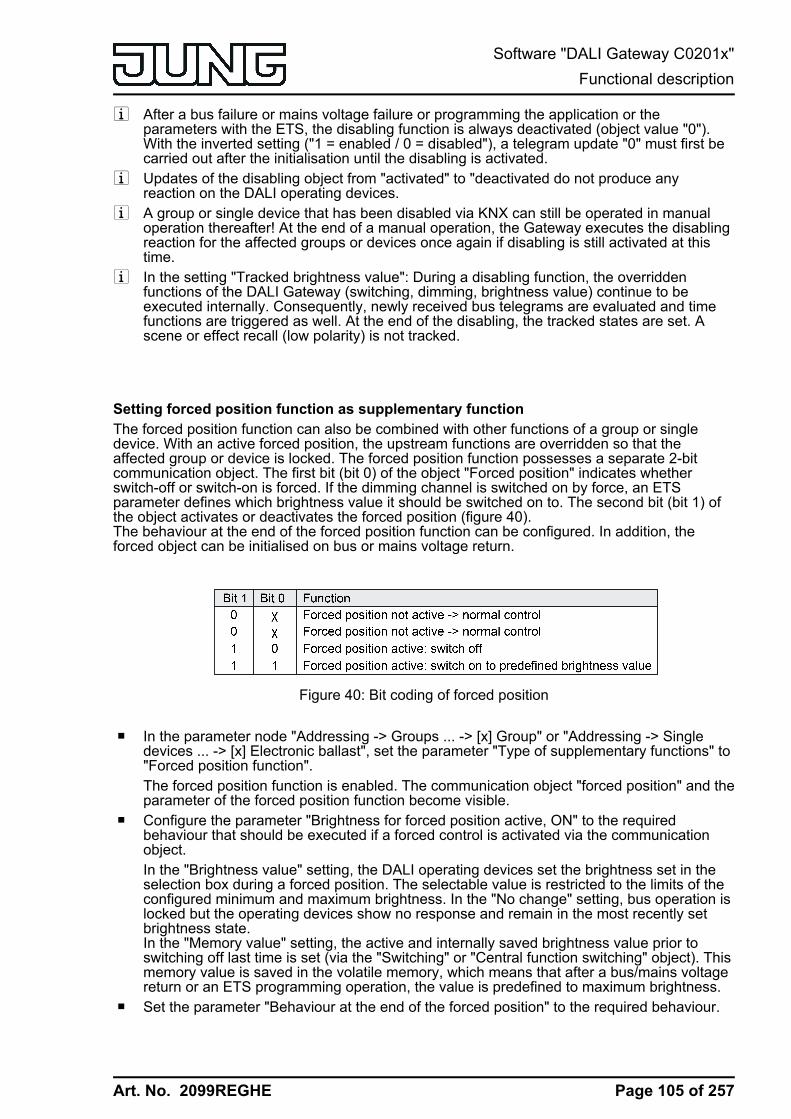
Art. No. 2099REGHE
i After a bus failure or mains voltage failure or programming the application or theparameters with the ETS, the disabling function is always deactivated (object value "0").With the inverted setting ("1 = enabled / 0 = disabled"), a telegram update "0" must first becarried out after the initialisation until the disabling is activated.
i Updates of the disabling object from "activated" to "deactivated do not produce anyreaction on the DALI operating devices.
i A group or single device that has been disabled via KNX can still be operated in manualoperation thereafter! At the end of a manual operation, the Gateway executes the disablingreaction for the affected groups or devices once again if disabling is still activated at thistime.
i In the setting "Tracked brightness value": During a disabling function, the overriddenfunctions of the DALI Gateway (switching, dimming, brightness value) continue to beexecuted internally. Consequently, newly received bus telegrams are evaluated and timefunctions are triggered as well. At the end of the disabling, the tracked states are set. Ascene or effect recall (low polarity) is not tracked.
Setting forced position function as supplementary functionThe forced position function can also be combined with other functions of a group or singledevice. With an active forced position, the upstream functions are overridden so that theaffected group or device is locked. The forced position function possesses a separate 2-bitcommunication object. The first bit (bit 0) of the object "Forced position" indicates whetherswitch-off or switch-on is forced. If the dimming channel is switched on by force, an ETSparameter defines which brightness value it should be switched on to. The second bit (bit 1) ofthe object activates or deactivates the forced position (figure 40).The behaviour at the end of the forced position function can be configured. In addition, theforced object can be initialised on bus or mains voltage return.
Figure 40: Bit coding of forced position
o In the parameter node "Addressing -> Groups ... -> [x] Group" or "Addressing -> Singledevices ... -> [x] Electronic ballast", set the parameter "Type of supplementary functions" to"Forced position function".The forced position function is enabled. The communication object "forced position" and theparameter of the forced position function become visible.
o Configure the parameter "Brightness for forced position active, ON" to the requiredbehaviour that should be executed if a forced control is activated via the communicationobject.In the "Brightness value" setting, the DALI operating devices set the brightness set in theselection box during a forced position. The selectable value is restricted to the limits of theconfigured minimum and maximum brightness. In the "No change" setting, bus operation islocked but the operating devices show no response and remain in the most recently setbrightness state.In the "Memory value" setting, the active and internally saved brightness value prior toswitching off last time is set (via the "Switching" or "Central function switching" object). Thismemory value is saved in the volatile memory, which means that after a bus/mains voltagereturn or an ETS programming operation, the value is predefined to maximum brightness.
o Set the parameter "Behaviour at the end of the forced position" to the required behaviour.
Page 105 of 257
Software "DALI Gateway C0201x"Functional description
Art. No. 2099REGHE
At the end of the forced position, the configured behaviour will be executed. Bus operationis enabled again. In the "No change" setting, the operating devices show no response andremain in the brightness state last selected by the forced position. In "tracked brightnessvalue", the state received during the forced position function or the brightness valueadjusted before the function can be tracked at the end of the forced position. Any timefunctions still in progress will also be taken into account if necessary.
i Updates of the forced position object from "forced position active" to "forced position active"while maintaining the switching status or from "forced position inactive" to "forced positioninactive" show no reaction.
i A group or single device that has been disabled via KNX can still be operated in manualoperation thereafter! At the end of a manual operation, the Gateway executes the forcedreaction for the affected groups or devices once again if the forced position is still activatedat this time.
i In the setting "tracked brightness value" at the end of the forced position: During a forcedposition, the overridden functions of the DALI Gateway (switching, dimming, brightnessvalue) continue to be executed internally. Consequently, newly received bus telegrams areevaluated and time functions are triggered as well. At the forced end, the tracked states areset. A scene or effect recall (low polarity) is not tracked.
i The current state of the object of the forced position function will be stored in case of bus ormains voltage failure.
o Set the parameter "behaviour after bus voltage return" to the required behaviour.After bus or mains voltage return, the configured state is transferred to the "Forcedposition" communication object. When a forced position is activated, the DALI group or thesingle device is immediately activated and interlocked accordingly by forced control afterbus/mains voltage return until a forced control takes place via the bus. In this case, theparameter "Behaviour after bus voltage return" will not be evaluated.In the "State before bus voltage failure" setting, after bus or mains voltage return, the lastexisting and internally forced position state that was stored before the bus or mains voltagefailure will be tracked. An ETS programming operation deletes the stored state (reaction inthat case same as with "no forced position active"). If the tracked state corresponds to "Noforced position active", the force-independent parameter "Behaviour after bus voltagereturn" will be executed on return of bus voltage. If forced position is activated, the DALIoperating devices are switched on to the brightness value predefined by the parameter"Switch-on brightness for forced position, ON".
i After programming the application or parameters with the ETS, the forced position functionis always deactivated (object value "0").
Page 106 of 257
Software "DALI Gateway C0201x"Functional description

Art. No. 2099REGHE
4.2.4.3.5 Feedback functions
Feedback for switching status and brightness valueThe DALI Gateway can track the current switching state and brightness value of a DALI groupor single device via separate feedback objects and can also transmit them to the bus, if the busvoltage is on. The following feedback objects can be enabled independently of each other foreach DALI group and each configured single device ...- Feedback switching status (1-bit),- Feedback brightness value (1-byte).
The Gateway calculates the object value of the feedback objects during each switching ordimming operation. The Gateway tracks the switching state or brightness value and updates thefeedback objects, even when a group or single device is activated by the manual operation orscene function or by using effects.
The switching status feedback object is updated after the following events...- Immediately after switch-on, (if necessary, first after a switch-on delay has elapsed and at
the beginning of a soft ON dimming procedure / also after a staircase function),- after switch-off, (if necessary, first after a run-on-time has elapsed and at the end of a soft
OFF dimming procedure / also after a staircase function),- immediately after switching off by means of the automatic switch-off function,- at the beginning of a dimming procedure when dimming ON (relatively high dimming or
brightness value = 1…100 %),- at the end of a dimming procedure when dimming OFF (brightness value = 0 %),- If the switching state changes in normal operation (therefore not for dimming procedures
that do not change the switching state e.g. from 10 % to 50 % brightness),- At the start or end of a disabling or forced position function (if the switching state changes
as a result),- On scene recall or effect run-through (always when the switching state changes as a
result),- On bus/mains voltage return or at the end of an ETS programming operation (possibly also
delayed / exception: "No change").
The brightness value feedback object is updated after the following events...- at the end of a relative (4-bit) or absolute (1-byte) dimming procedure.- after switch-on, if the switch-on brightness is set (if necessary, first after a switch-on delay
has elapsed and at the end of a soft ON dimming procedure / also after a staircasefunction),
- after switch-off, (if necessary, first after a run-on-time has elapsed and at the end of a softOFF dimming procedure / also after a staircase function),
- immediately after switching off by means of the automatic switch-off function,- if, in normal operation, the brightness value changes (if a brightness value specification
exceeds/undershoots the maximum/minimum brightness as a result of relative or absolutedimming from outside or exceeds the maximum brightness, the Gateway updatesbrightness value feedback according to the maximum brightness or minimum brightness),
- at the start or end of a disabling or forced position function (if the brightness value changesas a result),
- on scene recall or effect run-through (if the brightness value changes as a result),- always on bus/mains voltage return or at the end of an ETS programming operation
(possibly also delayed / exception: "No change").
i In the case of enabling function as supplementary function: A flashing DALI group or singledevice is always signalled back as "switched on" and with switch-on brightness. Switchingstatus feedbacks are also transmitted for disabled groups or devices when the outputs arereadjusted by a manual operation, for example.
Page 107 of 257
Software "DALI Gateway C0201x"Functional description
Art. No. 2099REGHE
Activate switching status feedbackThe switching status feedback can be used as an active message object or as a passive statusobject. As an active message object, the switching status feedback is also directly transmitted tothe bus whenever there is an update. As a passive status object, there is no telegramtransmission after an update. In this case, the object value must be read out. The ETSautomatically sets the object communication flags required for proper functioning.The parameter "Feedback switching status ?" is available separately for each DALI group oreach single device in the parameter node "Addressing -> Groups ... - [x] Group -> Switching" or"Addressing -> Single devices ... - [x] Electronic ballast -> Switching".o Set the parameter to "yes, feedback object is active signalling object".
The "Switching status feedback" object is enabled. The switching status is transmitted oncethe status is updated. An automatic telegram transmission of the feedback takes place afterbus/mains voltage return or after programming with the ETS (exception: "No change").
o Set the parameter to "yes, feedback object is passive status object".The "Switching status feedback" object is enabled. The switching status will be transmittedin response only if the feedback object is read out from by the bus. No automatic telegramtransmission of the feedback takes place after bus or mains voltage return or afterprogramming with the ETS.
Presetting update of the switching status feedbackIn the ETS you can specify when the Gateway should update the feedback value for theswitching status in case of an actively transmitting communication object. The object valueupdated by the Gateway is then signalled actively to the bus.The parameter "Updating the object value for switching status feedback" is created separatelyfor each DALI group or each single device in the parameter node "Addressing -> Groups ... - [x]Group -> Switching" or "Addressing -> Single devices ... - [x] Electronic ballast -> Switching".The switching status feedback must be configured to actively transmitting.o Set the parameter to "After each update of the inputs".
The Gateway updates the feedback value in the object once a new telegram is received onthe input objects "Switching" or "Central switching". With an actively transmitting feedbackobject, a new telegram is also then actively transmitted to the bus each time. The telegramvalue of the feedback does not necessarily have to change in the process. Hence, acorresponding switching status feedback is also generated on the "Switching" object suchas in the case of cyclical telegrams for example.In addition, feedback is transmitted at the beginning or end of a disabling or forced positionfunction, and also during an effect run-through, even if the feedback state does not change.
o Set the parameter to "Only if the feedback value changes".The Gateway only updates the feedback value in the object if the telegram value(e.g. "OFF" to "ON") also changes. If the telegram value of the feedback does not change(e.g. in the case of cyclical telegrams to the "Switching" object with the same telegramvalue), the feedback then remains unchanged. Consequently, with an actively transmittingfeedback object, no telegram with the same content will be transmitted repeatedly either.This setting is recommendable, for instance, if the "Switching" and "Switching feedback"objects are linked to an identical group address. This is often the case when activating bymeans of light scene push-button sensors (recall and storage function).
Setting the switching status feedback on bus or mains voltage return or afterprogramming with the ETSIf used as an active message object, the switching status feedback state is transmitted to thebus after bus or mains voltage return or after programming with the ETS. In these cases, thefeedback telegram can be delayed with the delay being preset globally for all DALI groupstogether (cf. "Delay after bus/mains voltage return").
Page 108 of 257
Software "DALI Gateway C0201x"Functional description

Art. No. 2099REGHE
o Set the parameter "Time delay for feedback after bus voltage return" in the parameter node"Addressing -> Groups ... - [x] Group -> Switching" or "Addressing -> Single devices ... - [x]Electronic ballast –> Switching" to "yes".The switching status feedback is transmitted after a delay after bus or mains voltage returnor after programming with the ETS. No feedback telegram is transmitted during a runningdelay, even if the switching state changes during this delay.
o Set the parameter "Time delay for feedback telegram after bus voltage return" to "no".The switching status feedback is transmitted immediately after bus or mains voltage returnor after programming with the ETS.
i The behaviour of a group or a single device after bus voltage return and after an ETSprogramming operation can be configured in the ETS and set to "No change". In this case,the communication objects of the Gateway are initialised with "0". In this case, theswitching status feedback only corresponds to the 'true' brightness state when the group orthe single device has been controlled at least once via the bus or by manual operation. Inthis setting, feedback objects set as actively transmitting do not transmit a telegram.
Presetting the cyclical transmission function for the switching status feedback telegramThe switching status feedback telegram can also be transmitted cyclically via the activemessage object in addition to the transmission after updating.o Set the parameter "Cyclical transmission of feedback telegram?" in the parameter node
"Addressing -> Groups ... - [x] Group -> Switching" or "Addressing -> Single devices ... - [x]Electronic ballast –> Switching" to "yes".Cyclical transmission is activated.
o Set the parameter "Cyclical transmission of feedback telegram" to "no".Cyclical transmission is deactivated so that the feedback telegram is only transmitted whena switching status is updated.
i The cycle time is defined centrally for all DALI groups and single devices in the parameternode "General -> Status and feedback".
i During an active delay, no feedback telegram will be transmitted even if a switching statechanges.
Activate brightness value feedbackThe brightness value feedback can be used as an active message object or as a passive statusobject. As an active message object, the brightness value feedback information is also directlytransmitted to the bus whenever there is an update. As a passive status object, there is notelegram transmission after an update. In this case, the object value must be read out. The ETSautomatically sets the object communication flags required for proper functioning.The parameter "Feedback brightness value ?" is available separately for each DALI group oreach single device in the parameter node "Addressing -> Groups ... - [x] Group -> Dimming" or"Addressing -> Single devices ... - [x] Electronic ballast -> Dimming".o Set the parameter to "yes, feedback object is active signalling object".
The "brightness value feedback" object is enabled. The brightness value is transmittedonce this is updated. An automatic telegram transmission of the feedback takes place afterbus/mains voltage return or after programming with the ETS (exception: "No change").
o Set the parameter to "yes, feedback object is passive status object".
Page 109 of 257
Software "DALI Gateway C0201x"Functional description
Art. No. 2099REGHE
The "brightness value feedback" object is enabled. The brightness value will be transmittedin response only if the feedback object is read out from by the bus. No automatic telegramtransmission of the feedback takes place after bus or mains voltage return or afterprogramming with the ETS.
Presetting update of the brightness value feedbackIn the ETS, you can specify when the Gateway should update the feedback value for thebrightness value in case of an actively transmitting communication object. The object valueupdated by the Gateway is then signalled actively to the bus.The parameter "Updating the object value for brightness value feedback" is created separatelyfor each DALI group or each single device in the parameter node "Addressing -> Groups ... - [x]Group -> Dimming" or "Addressing -> Single devices ... - [x] Electronic ballast -> Dimming".The brightness value feedback must be configured to "active message object".o Set the parameter to "After each update of the inputs".
The Gateway updates the feedback value in the object once a new telegram is received onthe input object "brightness feedback". With an actively transmitting feedback object, a newtelegram is also then actively transmitted to the bus each time. The telegram value of thefeedback does not necessarily have to change in the process. Hence, a correspondingbrightness value feedback is also generated on the "brightness value feedback" objectsuch as in the case of cyclical telegrams for example.In addition, feedback is transmitted at the beginning or end of a disabling or forced positionfunction, and also during an effect run-through, even if the feedback value does notchange.
o Set the parameter to "Only if the feedback value changes".The Gateway only updates the feedback value in the object if the telegram value(e.g. "0 %" to "100 %") also changes. If the telegram value of the feedback does notchange (e.g. in the case of cyclical telegrams to the "brightness value" object with the sametelegram value), the feedback then remains unchanged. Consequently, with an activelytransmitting feedback object, no telegram with the same content will be transmittedrepeatedly either.This setting is recommendable, for instance, if the "brightness value" and "brightness valuefeedback" objects are linked to an identical group address. This is often the case whenactivating by means of light scene push-button sensors (recall and storage function).
Setting the brightness value feedback on bus or mains voltage return or afterprogramming with the ETSIf used as an active message object, the brightness value feedback state is transmitted to thebus after bus or mains voltage return or after programming with the ETS. In these cases, thefeedback telegram can be delayed with the delay being preset globally for all DALI groupstogether (cf. "Delay after bus/mains voltage return").o Set the parameter "Time delay for feedback after bus voltage return" in the parameter node
"Addressing -> Groups ... - [x] Group -> Dimming" or "Addressing -> Single devices ... - [x]Electronic ballast -> Dimming" to "yes".The brightness value feedback is transmitted after a delay after bus or mains voltage returnor after programming with the ETS. No feedback telegram is transmitted during a runningdelay, even if the brightness value changes during this delay.
o Set the parameter "Time delay for feedback telegram after bus voltage return" to "no".The brightness value feedback is transmitted immediately after bus or mains voltage returnor after programming with the ETS.
Page 110 of 257
Software "DALI Gateway C0201x"Functional description
Art. No. 2099REGHE
i The behaviour of a group or a single device after bus voltage return and after an ETSprogramming operation can be configured in the ETS and set to "No change". In this case,the communication objects of the Gateway are initialised with "0". In this case, thebrightness value feedback only corresponds to the 'true' brightness state when the group orthe single device has been controlled at least once via the bus or by manual operation. Inthis setting, feedback objects set as actively transmitting do not transmit a telegram.
Presetting the cyclical transmission function for the brightness value feedback telegramThe brightness value feedback telegram can also be transmitted cyclically via the activemessage object in addition to the transmission after updating.o Set the parameter "Cyclical transmission of feedback telegram?" in the parameter node
"Addressing -> Groups ... - [x] Group -> Dimming" or "Addressing -> Single devices ... - [x]Electronic ballast -> Dimming" to "yes".Cyclical transmission is activated.
o Set the parameter "Cyclical transmission of feedback telegram" to "no".Cyclical transmission is deactivated so that the feedback telegram is only transmitted to thebus when the brightness value is updated.
i The cycle time is defined centrally for all DALI groups and single devices in the parameternode "General -> Status and feedback".
i During an active delay, no feedback telegram will be transmitted even if a brightness valuechanges.
Feedback of the colour temperatureThe DALI Gateway can track the set colour temperature of a DALI group and single device via aseparate 2-byte feedback object according to DPT 7.600 and can also transmit it to the bus, ifthe bus voltage is on. In addition, the Gateway can display whether an externally specifiedcolour temperature is valid (object value "ON") or invalid (object value "OFF) by means of aseparate 1-bit feedback object. An invalid colour temperature exists if the specified valueviolates the set limits of the minimum and maximum colour temperature.The Gateway determines the object value of the feedback objects each time the colourtemperature is influenced. The Gateway tracks the colour temperature value and updates thefeedback objects even when a group or single device is activated by the scene function or byusing effects.
The feedback object "FB absolute colour temperature (K)" is updated after the followingevents...- after a completed relative or absolute dimming operation of the colour temperature, but
only if the DALI group or single device is also switched on after mains voltage return(brightness unequal "0 %"),
- immediately after switching on a DALI group or single device, but only if the colourtemperature value differs from the last value that was fed back,
- on scene recall or effect run-through (always when the colour temperature changes as aresult),
- after bus voltage return (possibly also delayed), but only if the DALI group or single deviceis also switched on after mains voltage return (brightness unequal "0 %"),
- after mains voltage return (possibly also delayed), but only if the DALI group or singledevice is activated by the Gateway after mains voltage return (brightness unequal "0 %").
i The communication objects of the Gateway are initialised with "0" after an ETSprogramming operation. In this case, the feedback of the colour temperature only thencorresponds to a valid value when the colour temperature of the group or single device wascontrolled at least once via the KNX and the transmission criterion of the feedback wasmet. Actively transmitting feedback objects of the colour temperature automatically do nottransmit any telegram immediately after an ETS programming operation.
Page 111 of 257
Software "DALI Gateway C0201x"Functional description
Art. No. 2099REGHE
i If a colour temperature specification exceeds or undershoots the minimum or maximumcolour temperature as a result of relative or absolute dimming specified externally, theGateway updates a feedback according to the minimum or maximum temperature.
The feedback object "FB invalid colour temperature" is updated after the following events...- when predefining a new absolute colour temperature via the object "Absolute colour
temperature (K)" (depending on the configured transmission behaviour),- always after a device reset (ETS programming operation, bus/mains voltage return /
possibly also delayed), with the status "valid colour temperature".
Activating colour temperature feedbackThe colour temperature feedback must first be enabled in the ETS plug-in before it can be used.The parameter "Feedback of the current colour temperature?" enables the feedback and isavailable separately for each DALI group or each single device in the parameter node"Addressing -> Groups ... - [x] Group -> TW function colour temperature 1" or "Addressing ->Single devices ... - [x] Electronic ballast -> TW function colour temperature 1" created.o Set parameter to "yes".
The feedback of the colour temperature is available. The object "FB absolute colourtemperature (K)" is enabled.
o Set parameter to "no".The feedback of the colour temperature is not available.
Presetting transmission behaviour of the colour temperature feedbackThe colour temperature feedback can be used as an active message object or as a passivestatus object. As an active message object, the colour temperature feedback is also directlytransmitted to the bus whenever there is an update. As a passive status object, there is notelegram transmission after an update. In this case, the object value must be read out. The ETSautomatically sets the object communication flags required for proper functioning.The parameter "Feedback of the current colour temperature?" configures the function of thefeedback.o Set the parameter to "Active signalling object".
The feedback of the absolute colour temperature is transmitted once this it updated.o Set the parameter to "Passive status object".
The feedback of the absolute colour temperature will be transmitted in response only if thefeedback object is read out from the bus. No automatic telegram transmission of thefeedback takes place after bus or mains voltage return.
Setting update of the colour temperature feedbackIn the ETS you can specify when the Gateway should update the feedback value for the currentcolour temperature in case of an actively transmitting communication object. The object valueupdated by the Gateway is then signalled actively to the bus.The parameter "Updating the object value for current colour temperature value feedback" iscreated separately for each DALI group or each single device in the parameter node"Addressing -> Groups ... - [x] Group -> TW function colour temperature 1" or "Addressing ->Single devices ... - [x] Electronic ballast -> TW function colour temperature 1" created.The feedback of the current colour temperature must be configured to "active message object".o Set the parameter to "After each update of the inputs".
Page 112 of 257
Software "DALI Gateway C0201x"Functional description

Art. No. 2099REGHE
The Gateway updates the feedback value in the object once a new telegram is received onthe input object "Absolute colour temperature (K)", but only if the DALI group or singledevice is also switched on. With an actively transmitting feedback object, a new telegram isalso then actively transmitted to the bus each time. The telegram value of the feedbackdoes not necessarily have to change in the process. Hence, a corresponding colourtemperature feedback is also generated on the object "Absolute colour temperature (K)"such as in the case of cyclical telegrams, for example.
o Set the parameter to "Only if the feedback value changes".The Gateway only updates the feedback value in the object if the telegram value alsochanges. This only takes place, however, if the DALI group or single device is alsoswitched on. If the telegram value of the feedback does not change when switched on (e.g.in the case of cyclical telegrams to the "Absolute colour temperature (K)" object with thesame telegram value), the feedback then remains unchanged. Consequently, with anactively transmitting feedback object, no telegram with the same content will be transmittedrepeatedly either.This setting is recommendable, for instance, if the "Absolute colour temperature (K)" and"FB absolute colour temperature (K)" objects are linked to an identical group address. Thisis often the case when activating by means of light scene push-button sensors (recall andstorage function).
Setting the colour temperature feedback on bus or mains voltage returnIf used as an active message object, the colour temperature feedback state is transmitted to thebus after bus or mains voltage return, but only if the DALI group or single device is alsoswitched on (brightness unequal "0 %"). In these cases, the feedback telegram can be delayedwith the delay being preset globally for all DALI groups together (cf. "Delay after bus/mainsvoltage return").The feedback of the current colour temperature must be configured to "active message object".o Set the parameter "Time delay for feedback after bus voltage return" in the parameter node
"Addressing -> Groups ... - [x] Group -> TW function colour temperature 1" or "Addressing -> Single devices ... - [x] Electronic ballast -> Set TW function colour temperature 1" to"yes".The colour temperature feedback is transmitted with a delay after bus or mains voltagereturn. No feedback telegram is transmitted during a running delay, even if the colourtemperature changes during this delay.
o Set the parameter "Time delay for feedback telegram after bus voltage return" to "no".The colour temperature feedback is transmitted immediately after bus or mains voltagereturn.
i After a mains voltage return, only telegrams corresponding to the effective colourtemperature in the DALI Gateway are transmitted when the DALI group or single device isactively on after mains voltage return (brightness unequal "0 %").
i The communication objects of the Gateway are initialised with "0" after an ETSprogramming operation. In this case, the feedback of the colour temperature only thencorresponds to a valid value when the colour temperature of the group or single device wascontrolled at least once via the KNX and the transmission criterion of the feedback wasmet. Actively transmitting feedback objects of the colour temperature automatically do nottransmit any telegram immediately after an ETS programming operation.
Presetting the cyclical transmission of the colour temperature feedbackThe colour temperature feedback telegram can also be transmitted cyclically via the activemessage object in addition to the transmission after updating.The feedback of the current colour temperature must be configured to "active message object".
Page 113 of 257
Software "DALI Gateway C0201x"Functional description

Art. No. 2099REGHE
o Set the parameter "Cyclical transmission of feedback telegram?" in the parameter node"Addressing -> Groups ... - [x] Group -> TW function colour temperature 1" or "Addressing -> Single devices ... - [x] Electronic ballast -> Set TW function colour temperature 1" to"yes".Cyclical transmission is activated.
o Set the parameter "Cyclical transmission of feedback telegram" to "no".Cyclical transmission is deactivated so that the feedback telegram is transmitted to the busonly when updating a colour temperature.
i The cycle time is defined centrally for all DALI groups and single devices in the parameternode "General -> Status and feedback".
i During an active delay, no feedback telegram will be transmitted even if a colourtemperature changes.
Activating "invalid colour temperature" feedbackThe feedback of an invalid colour temperature must first be enabled in the ETS plug-in before itcan be used. The parameter "Feedback of an invalid colour temperature?" enables thefeedback and is available separately for each DALI group or each single device in theparameter node "Addressing -> Groups ... - [x] Group -> TW function colour temperature 2" or"Addressing -> Single devices ... - [x] Electronic ballast -> TW function colour temperature 2"created.o Set parameter to "yes".
The feedback of an invalid colour temperature is available. The object "FB invalid colourtemperature" is enabled.
o Set parameter to "no".The feedback of an invalid colour temperature is not available.
Presetting transmission behaviour of the "invalid colour temperature" feedbackThe feedback of an invalid colour temperature can be used as an active message object or as apassive status object. As an active message object, the feedback is also directly transmitted tothe bus whenever there is an update of the object "FB absolute colour temperature (K)". As apassive status object, there is no telegram transmission after an update. In this case, the objectvalue must be read out. The ETS automatically sets the object communication flags required forproper functioning.The parameter "Feedback of an invalid colour temperature?" configures the function of thefeedback.o Set the parameter to "Active signalling object".
The feedback of an invalid colour temperature is transmitted once this it updated.i After a device reset (ETS programming operation, mains voltage return), the status "valid
colour temperature" is always transmitted if an object is actively transmitting.o Set the parameter to "Passive status object".
The feedback of an invalid colour temperature will be transmitted in response only if thefeedback object is read out from the bus.
Presetting update of the "invalid colour temperature" feedbackIn the ETS you can specify when the Gateway should update the feedback value for an invalidcolour temperature in case of an actively transmitting communication object. The object value
Page 114 of 257
Software "DALI Gateway C0201x"Functional description

Art. No. 2099REGHE
updated by the Gateway is then signalled actively to the bus.The parameter "Updating the object value for invalid colour temperature value feedback" iscreated separately for each DALI group or each single device in the parameter node"Addressing -> Groups ... - [x] Group -> TW function colour temperature 2" or "Addressing ->Single devices ... - [x] Electronic ballast -> TW function colour temperature 2" created.The feedback of an invalid colour temperature must be configured to "active message object".o Set the parameter to "After each update of the inputs".
The Gateway updates the feedback value in the object once a new telegram is received onthe input object "Absolute colour temperature (K)". With an actively transmitting feedbackobject, a new telegram is also then actively transmitted to the bus each time. The telegramvalue of the feedback does not necessarily have to change in the process. Hence, acorresponding "invalid colour temperature" feedback is also generated on the "Absolutecolour temperature (K)" object, such as in the case of cyclical telegrams for example.
o Set the parameter to "Only if the feedback value changes".The Gateway only updates the feedback value in the object if the telegram value alsochanges. If the telegram value of the feedback does not change (e.g. in the case of cyclicaltelegrams to the "Absolute colour temperature (K)" object with the same telegram value),the feedback then remains unchanged. Consequently, with an actively transmittingfeedback object, no telegram with the same content will be transmitted repeatedly either.
Setting the "invalid colour temperature" feedback on bus or mains voltage return or afteran ETS programming operationIf used as an active message object, the switching status feedback of an invalid colourtemperature is transmitted to the bus after bus or mains voltage return or after an ETSprogramming operation. In these cases, the feedback telegram can be delayed with the delaybeing preset globally for all DALI groups together (cf. "Delay after bus/mains voltage return").The feedback of an invalid colour temperature must be configured to "active message object".o Set the parameter "Time delay for feedback after bus voltage return" in the parameter node
"Addressing -> Groups ... - [x] Group -> TW function colour temperature 2" or "Addressing -> Single devices ... - [x] Electronic ballast -> Set TW function colour temperature 2" to"yes".The "invalid colour temperature" feedback is transmitted with a delay after bus or mainsvoltage return or after an ETS programming operation. No feedback telegram is transmittedduring a running delay, even if the colour temperature changes during this delay.
o Set the parameter "Time delay for feedback telegram after bus voltage return" to "no".The "invalid colour temperature" feedback is transmitted immediately after bus or mainsvoltage return or after an ETS programming operation.
i After a device reset (ETS programming operation, mains voltage return), the status "validcolour temperature" is always transmitted if an object is actively transmitting.
Presetting the cyclical transmission of the "invalid colour temperature" feedbackThe feedback telegram of an invalid colour temperature can also be transmitted cyclically viathe active message object in addition to the transmission after updating.The feedback of an invalid colour temperature must be configured to "active message object".o Set the parameter "Cyclical transmission of feedback telegram?" in the parameter node
"Addressing -> Groups ... - [x] Group -> TW function colour temperature 2" or "Addressing -> Single devices ... - [x] Electronic ballast -> Set TW function colour temperature 2" to"yes".Cyclical transmission is activated.
Page 115 of 257
Software "DALI Gateway C0201x"Functional description
Art. No. 2099REGHE
o Set the parameter "Cyclical transmission of feedback telegram" to "no".Cyclical transmission is deactivated so that the feedback telegram is transmitted to the busonly when updating the feedback.
i The cycle time is defined centrally for all DALI groups and single devices in the parameternode "General -> Status and feedback".
Page 116 of 257
Software "DALI Gateway C0201x"Functional description

Art. No. 2099REGHE
4.2.4.3.6 Automatic switch-off
Automatic switch-offThe switch-off function permits automatic switching of a DALI group or a single device after abrightness value was dimmed or jumped to and this new brightness value is below a switch-offbrightness set in the ETS. A delay can be configured optionally until switching off (figure 41).The switch-off function is activated after reaching a constant brightness value, i.e. after acompleted dimming procedure through absolute or relative dimming. A new dimming operation,which ends below switch-off brightness starts, starts any time delay which may be present. Inthe same way, the switch-off function is interrupted if the switch-off brightness is exceed duringa dimming operation.The automatic switch-off function, for example, not only makes it possible to set the lighting tominimum brightness but to switch off by means of relative dimming as well. A further application,for example, is time-controlled "Good night switch-off" of a dimmed children's room lighting.
Figure 41: Dimming and switching behaviour of the automatic switch-off function
i Switching off always takes place without soft OFF function, i.e. jumping.i The switch-off brightness in the dimmable brightness range can be set between the
configured maximum and minimum brightness. Automatic switch-off does not take place if"Switch-off brightness = Minimum brightness" is set, since the switch-off brightness cannotbe undershot. The switch-off function is always active if the switch-off brightness isconfigured to maximum brightness and the maximum brightness is randomly undershot.
i The feedback objects for switching state and brightness value are updated by theautomatic switch-off function after switching off.
The switch-off function can also be combined with other functions of the DALI Gateway. Itshould be noted that the disabling function, the forced position function, the scene function andthe effect function override the switch-off function. The automatic switch-off can only beactivated by a dimming procedure initiated via the 4-bit ("dimming") or 1-byte ("brightnessvalue") communication object. If the switch-off function is overridden, the DALI Gatewayterminates the processing of the delay time and the evaluation of the switch-off brightness.Switching on (switch-on brightness) using the communication object "Switching" does notactivate the switch-off function.
Page 117 of 257
Software "DALI Gateway C0201x"Functional description

Art. No. 2099REGHE
Enabling automatic switch-off functionIn the plug-in of the DALI Gateway, the automatic switch-off function can be set separately foreach group and each single device.o Set the parameter "Automatic switch-off when undershooting a brightness ?" in the
parameter node "Addressing -> Groups ... - [x] Group -> Dimming" or "Addressing -> Singledevices ... - [x] Electronic ballast -> Dimming" to "yes".The automatic switch-off function is enabled. Additional parameters become visible.
Setting the switch-off brightnessThe switch-off brightness must be defined for the switch-off function. The switch-off function isset separately for each DALI device and each single device.The switch-off function must be enabled.o Set the parameter "Switch-off when brightness value less than" in the parameter node
"Addressing -> Groups ... - [x] Group -> Dimming" or "Addressing -> Single devices ... - [x]Electronic ballast -> Dimming" to the required brightness value.Once a dimming procedure causes a value to fall below the parameterised shutoffbrightness and once the brightness has been set to constant, the DALI group or the singledevice switches off or alternatively starts the delay until switching off. The parameterselection is restricted to the limits of the minimum and maximum brightness.
Setting the delay of the switch-off functionA time delay can be activated before the switch-off function switches-off automatically afterundershooting the switch-off brightness at the end of a dimming procedure. The time delay canoptionally be enabled separately for each DALI group and each single device.The switch-off function must be enabled.o Set the parameter "Delay until switching off ?" in the parameter node "Addressing ->
Groups ... - [x] Group -> Dimming" or "Addressing -> Single devices ... - [x] Electronicballast -> Dimming" to "yes". Configure the parameter "Delay until switching off" to therequired time.Once a dimming procedure causes a value to fall below the parameterised shutoffbrightness and once the brightness has been set to constant, the DALI Gateway triggersthe delay time. The DALI Group or the single device concerned switches off for good oncethe delay time has elapsed. The delay time can be re-triggered by further dimmingprocedures.
Page 118 of 257
Software "DALI Gateway C0201x"Functional description
Art. No. 2099REGHE
4.2.4.3.7 Switch-on and switch-off behaviour
Time delaysUp to two time functions can be preset independently of each other for each DALI group andeach single device. The time functions affect the communication objects "Switching" or "Centralfunction switching" only (if the central function is activated for the group or the single device)and delay the object value received depending on the telegram polarity .
Activating switch-on delayThe switch-on delay can be set separately in the plug-in of the DALI Gateway for each groupand each single device.o In the parameter node "Addressing -> Groups ... - [x] Group -> Switch-on/Switch-off
behaviour" or "Addressing -> Single devices ... - [x] Electronic ballast -> Switch-on/Switch-off behaviour", set the parameter "Selection of time delay" to "Switch-on delay" or to"switch-on delay and switch-off delay". Configure the desired switch-on delay.The switch-on delay is enabled. After reception of an ON telegram via the "switching"object, the configurable time is started. Another ON-telegram triggers the time only whenthe parameter "Switch-on delay retriggerable " is set to "yes". An OFF-telegram receivedduring the ON-delay will end the delay and sets the switching status to "OFF".
Activating switch-off delay The switch-off delay can be set separately in the plug-in of the DALI Gateway for each groupand each single device.o In the parameter node "Addressing -> Groups ... - [x] Group -> Switch-on/Switch-off
behaviour" or "Addressing -> Single devices ... - [x] Electronic ballast -> Switch-on/Switch-off behaviour", set the parameter "selection of time delay" to "switch-off delay" or to "switch-on delay and switch-off delay". Configure the desired switch-off delay.The switch-off delay is enabled. After reception of an OFF-telegram via the "switching"object, the configurable time is started. Another OFF-telegram triggers the time only whenthe parameter "switch-off delay retriggerable ?" is set to "yes". An ON-telegram receivedduring the OFF-delay will end the delay and sets the switching status to "ON".
i Feedback: If a time delay has been preset and if the switching state is changed via the"Switching" object, the time delay must have elapsed before feedback telegrams will betransmitted.
i At the end of a disabling function or forced position function, the brightness state receivedduring the function or adjusted before the function can be tracked. Residual times of timefunctions are also tracked if these had not yet fully elapsed at the time of the reactivation orforced control.
i The time delays do not influence the staircase function if this is enabled.i A time delay still in progress will be fully aborted by a reset of the actuator (bus/ mains
voltage failure or ETS programming).
Soft ON/OFF functionThe soft-functions permit a DALI group or a single device to be switched on or off at reducedspeed when a switching command is received via the "Switching" or "Central switching function"communication objects. If the soft ON function is activated, a dimming procedure is executeduntil the switch-on brightness when switching on. This also occurs if the DALI group of thesingle device is already switched on to a brightness value smaller than switch-on brightness.
Page 119 of 257
Software "DALI Gateway C0201x"Functional description
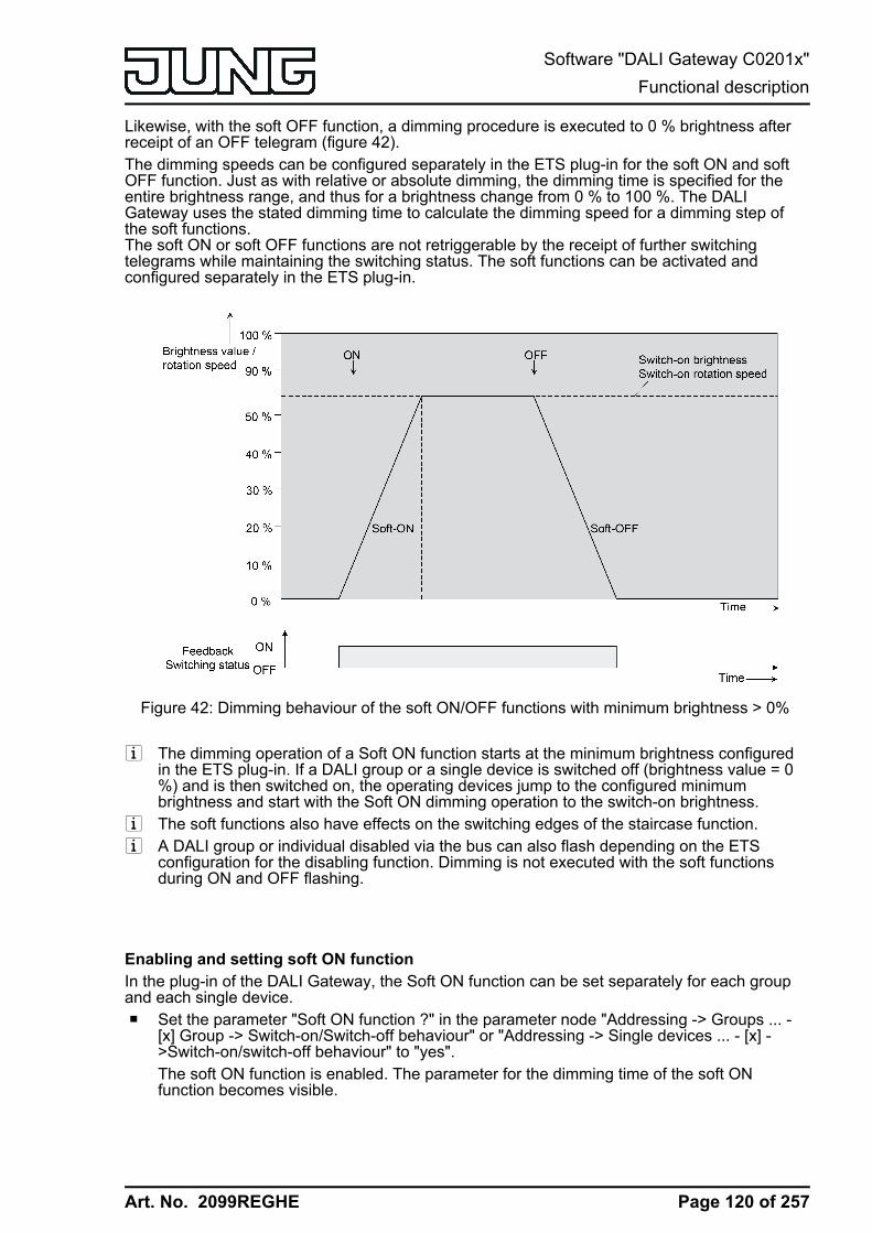
Art. No. 2099REGHE
Likewise, with the soft OFF function, a dimming procedure is executed to 0 % brightness afterreceipt of an OFF telegram (figure 42).The dimming speeds can be configured separately in the ETS plug-in for the soft ON and softOFF function. Just as with relative or absolute dimming, the dimming time is specified for theentire brightness range, and thus for a brightness change from 0 % to 100 %. The DALIGateway uses the stated dimming time to calculate the dimming speed for a dimming step ofthe soft functions.The soft ON or soft OFF functions are not retriggerable by the receipt of further switchingtelegrams while maintaining the switching status. The soft functions can be activated andconfigured separately in the ETS plug-in.
Figure 42: Dimming behaviour of the soft ON/OFF functions with minimum brightness > 0%
i The dimming operation of a Soft ON function starts at the minimum brightness configuredin the ETS plug-in. If a DALI group or a single device is switched off (brightness value = 0%) and is then switched on, the operating devices jump to the configured minimumbrightness and start with the Soft ON dimming operation to the switch-on brightness.
i The soft functions also have effects on the switching edges of the staircase function.i A DALI group or individual disabled via the bus can also flash depending on the ETS
configuration for the disabling function. Dimming is not executed with the soft functionsduring ON and OFF flashing.
Enabling and setting soft ON functionIn the plug-in of the DALI Gateway, the Soft ON function can be set separately for each groupand each single device.o Set the parameter "Soft ON function ?" in the parameter node "Addressing -> Groups ... -
[x] Group -> Switch-on/Switch-off behaviour" or "Addressing -> Single devices ... - [x] ->Switch-on/switch-off behaviour" to "yes".The soft ON function is enabled. The parameter for the dimming time of the soft ONfunction becomes visible.
Page 120 of 257
Software "DALI Gateway C0201x"Functional description
Art. No. 2099REGHE
o Configure the parameter "Time for soft ON (0...100 %)" to the required dimming time.
Enabling and setting soft OFF functionIn the plug-in of the DALI Gateway, the Soft OFF function can be set separately for each groupand each single device.o Set the parameter "Soft OFF function ?" in the parameter node "Addressing -> Groups ... -
[x] Group -> Switch-on/Switch-off behaviour" or "Addressing -> Single devices ... - [x] ->Switch-on/switch-off behaviour" to "yes".The soft OFF function is enabled. The parameter for the dimming time of the soft OFFfunction becomes visible.
o Configure the parameter "Time for soft OFF (0...100 %)" to the required dimming time.
Page 121 of 257
Software "DALI Gateway C0201x"Functional description
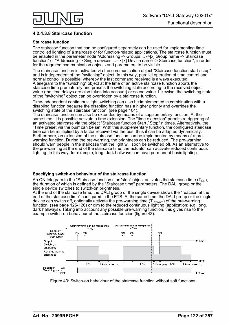
Art. No. 2099REGHE
4.2.4.3.8 Staircase function
Staircase functionThe staircase function that can be configured separately can be used for implementing time-controlled lighting of a staircase or for function-related applications. The staircase function mustbe enabled in the parameter node "Addressing -> Groups ... ->[x] Group name -> Staircasefunction" or "Addressing -> Single devices ... -> [x] Device name -> Staircase function", in orderfor the required communication objects and parameters to be visible.The staircase function is activated via the communication object "Staircase function start / stop"and is independent of the "switching" object. In this way, parallel operation of time control andnormal control is possible, whereby the last command received is always executed:A telegram to the "switching" object at the time of an active staircase function aborts thestaircase time prematurely and presets the switching state according to the received objectvalue (the time delays are also taken into account) or scene value. Likewise, the switching stateof the "switching" object can be overridden by a staircase function.Time-independent continuous light switching can also be implemented in combination with adisabling function because the disabling function has a higher priority and overrides theswitching state of the staircase function (see page 104).The staircase function can also be extended by means of a supplementary function. At thesame time, it is possible activate a time extension. The "time extension" permits retriggering ofan activated staircase via the object "Staircase function Start / Stop" n times. Alternatively, the"Time preset via the bus" can be set. With this supplementary function, the configured staircasetime can be multiplied by a factor received via the bus, thus it can be adapted dynamically.Furthermore, an extension of the staircase function can be implemented by means of a pre-warning function. During the pre-warning, the brightness can be reduced. The pre-warningshould warn people in the staircase that the light will soon be switched off. As an alternative tothe pre-warning at the end of the staircase time, the actuator can activate reduced continuouslighting. In this way, for example, long, dark hallways can have permanent basic lighting.
Specifying switch-on behaviour of the staircase functionAn ON telegram to the "Staircase function start/stop" object activates the staircase time (TON),the duration of which is defined by the "Staircase time" parameters. The DALI group or thesingle device switches to switch-on brightness.At the end of the staircase time, the DALI group or the single device shows the "reaction at theend of the staircase time" configured in the ETS. At the same time, the DALI group or the singledevice can switch off, optionally activate the pre-warning time (TPrewarn) of the pre-warningfunction (see page 125-126) or dim to the reduced continuous lighting (application: e.g. long,dark hallways). Taking into account any possible pre-warning function, this gives rise to theexample switch-on behaviour of the staircase function (figure 43).
Figure 43: Switch-on behaviour of the staircase function without soft functions
Page 122 of 257
Software "DALI Gateway C0201x"Functional description

Art. No. 2099REGHE
In addition, switching on can be influenced by the soft functions of the DALI Gateway. Takinginto account any soft ON and soft OFF function, this gives rise to the switch-on behaviour of thestaircase function shown below (figure 44).
Figure 44: Switch-on behaviour of the staircase function with soft functions (as an example withminimum brightness = 0 %)
o Set the parameter "Staircase function ?" in the parameter node "Addressing -> Groups ... ->[x] Group -> Staircase function" or "Addressing -> Single devices ... -> [x] Electronicballast -> Staircase function" to "yes".The staircase function is enabled. Additional parameters become visible.
o In the "Staircase time" parameter, configure the necessary switch-on time of the staircasefunction.
o Set the parameter "Staircase time retriggerable ?" to "yes".Every ON telegram received during the ON phase of the staircase time retriggers thestaircase time completely.
o The parameter "Staircase time retriggerable ?" is alternatively to "no".ON telegrams received during the ON phase of the staircase time are rejected. Thestaircase time is not retriggered.
i An ON telegram received during the pre-warning time or during the reduced continuouslighting triggers the staircase time independently of the parameter "Staircase timeretriggerable ?" always afterwards.
Specifying switch-off behaviour of the staircase functionIn the case of a staircase function, the reaction to an OFF telegram can also be configured onthe object "Staircase function start/stop". Without receiving an OFF telegram, at the end of thestaircase time, the DALI group or the single device always shows the "Reaction at the end ofthe staircase time" configured in the ETS. At the same time, the DALI group or the single devicecan switch off, optionally activate the pre-warning time (TPrewarn) of the pre-warning function ordim to the reduced continuous lighting (application: e.g. long, dark hallways).If, on the other hand, the DALI Group or the single device receives an OFF telegram via theobject "Staircase function start/stop", the actuator evaluates the parameter "Reaction to anOFF-telegram". In this case, the channel can react immediately to the OFF telegram and endthe staircase time prematurely. Alternatively, the OFF telegram can be ignored.Taking into account any possible pre-warning function, this gives rise to the example switch-offbehaviour of the staircase function (figure 45).
Page 123 of 257
Software "DALI Gateway C0201x"Functional description
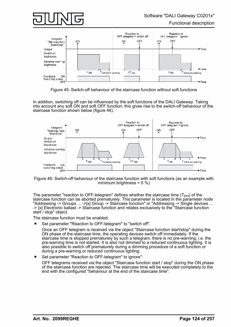
Art. No. 2099REGHE
Figure 45: Switch-off behaviour of the staircase function without soft functions
In addition, switching off can be influenced by the soft functions of the DALI Gateway. Takinginto account any soft ON and soft OFF function, this gives rise to the switch-off behaviour of thestaircase function shown below (figure 46).
Figure 46: Switch-off behaviour of the staircase function with soft functions (as an example withminimum brightness = 0 %)
The parameter "reaction to OFF-telegram" defines whether the staircase time (TEIN) of thestaircase function can be aborted prematurely. This parameter is located in the parameter node"Addressing -> Groups ... ->[x] Group -> Staircase function" or "Addressing -> Single devices ...-> [x] Electronic ballast -> Staircase function and relates exclusively to the "Staircase functionstart / stop" object.The staircase function must be enabled.o Set parameter "Reaction to OFF-telegram" to "switch off".
Once an OFF telegram is received via the object "Staircase function start/stop" during theON phase of the staircase time, the operating devices switch off immediately. If thestaircase time is stopped prematurely by such a telegram, there is no pre-warning, i.e. thepre-warning time is not started. It is also not dimmed to a reduced continuous lighting. It isalso possible to switch off prematurely during a dimming procedure of a soft function orduring a pre-warning or reduced continuous lighting.
o Set parameter "Reaction to OFF-telegram" to ignore".OFF telegrams received via the object "Staircase function start / stop" during the ON phaseof the staircase function are rejected. The staircase time will be executed completely to theend with the configured "behaviour at the end of the staircase time".
Page 124 of 257
Software "DALI Gateway C0201x"Functional description
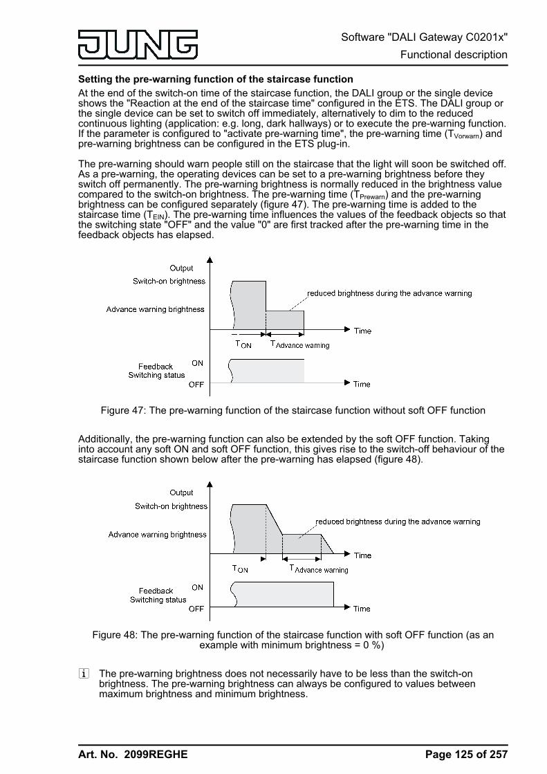
Art. No. 2099REGHE
Setting the pre-warning function of the staircase functionAt the end of the switch-on time of the staircase function, the DALI group or the single deviceshows the "Reaction at the end of the staircase time" configured in the ETS. The DALI group orthe single device can be set to switch off immediately, alternatively to dim to the reducedcontinuous lighting (application: e.g. long, dark hallways) or to execute the pre-warning function.If the parameter is configured to "activate pre-warning time", the pre-warning time (TVorwarn) andpre-warning brightness can be configured in the ETS plug-in.
The pre-warning should warn people still on the staircase that the light will soon be switched off.As a pre-warning, the operating devices can be set to a pre-warning brightness before theyswitch off permanently. The pre-warning brightness is normally reduced in the brightness valuecompared to the switch-on brightness. The pre-warning time (TPrewarn) and the pre-warningbrightness can be configured separately (figure 47). The pre-warning time is added to thestaircase time (TEIN). The pre-warning time influences the values of the feedback objects so thatthe switching state "OFF" and the value "0" are first tracked after the pre-warning time in thefeedback objects has elapsed.
Figure 47: The pre-warning function of the staircase function without soft OFF function
Additionally, the pre-warning function can also be extended by the soft OFF function. Takinginto account any soft ON and soft OFF function, this gives rise to the switch-off behaviour of thestaircase function shown below after the pre-warning has elapsed (figure 48).
Figure 48: The pre-warning function of the staircase function with soft OFF function (as anexample with minimum brightness = 0 %)
i The pre-warning brightness does not necessarily have to be less than the switch-onbrightness. The pre-warning brightness can always be configured to values betweenmaximum brightness and minimum brightness.
Page 125 of 257
Software "DALI Gateway C0201x"Functional description

Art. No. 2099REGHE
The staircase function must be enabled.o In the parameter node "Addressing -> Groups ... ->[x] Group -> Staircase function" or
"Addressing -> Single devices ... -> [x] Electronic ballast -> Staircase function", set theparameter "Reaction at the end of the staircase time" to "Activate pre-warning time".The pre-warning function is enabled. The desired pre-warning time (TVorwarn) can be preset.
o Configure the "pre-warning time".o Set the parameter "Reduced brightness" to the desired brightness value.
During the pre-warning time, the dimming channel is set to the configured brightness value.i An ON telegram to the object "Staircase function start/stop" while a pre-warning function is
still in progress stops the pre-warning time and always starts (independently of theparameter "Staircase time retriggerable ?") the staircase time anew. Even during the pre-warning time, the parameter "reaction to OFF telegram" is evaluated so that a pre-warningin progress can be terminated early by switching off.
i Using the automatic switch-off function: The reduced brightness of the pre-warning doesnot start the switch-off function after reaching or undershooting the switch-off brightness!
Setting continuous lighting of the staircase functionAt the end of the switch-on time of the staircase function, the Gateway shows the "Reaction atthe end of the staircase time" configured in the ETS for the appropriate DALI group or the singledevice. The DALI group or the single device can be set to switch off immediately, alternatively toexecute a pre-warning function, or to dim to the reduced continuous lighting. The reduction ofthe lighting to continuous lighting after the staircase time has elapsed is appropriate, forexample, if a certain degree of artificial light should be switched on permanently in long, darkhallways. Switching to switch-on brightness by activating the staircase function normally takesplace by additional presence detectors or motion detectors when people are present in thehallway.If the parameter "Reaction at the end of the staircase time" is configured to "activate reducedcontinuous lighting", the brightness for the continuous lighting can be configured in the ETS.The continuous brightness is normally reduced in the brightness value compared to the switch-on brightness (figure 49).The continuous lighting remains permanently active after the staircase time has elapsed. Onlywhen an ON telegram is received again via the object "Staircase function start/stop" does theDALI Gateway switch back to the switch-on brightness and start counting the staircase timeagain. The receipt of an OFF telegram via the object "Staircase function start/stop" onlyswitches the continuous lighting off if the parameter "Reaction to OFF-telegram" is configured to"Switch off".i A DALI group or a single device can always be switched on and off via the "Switching"
object, independently of the Staircase function. Consequently, continuous lighting will alsobe overridden if telegrams arrive via the "Switching" object.If permanent continuous lighting is desired, which cannot be influenced by the "Switching"object nor by the object of the staircase function, the disabling function should be used.
Page 126 of 257
Software "DALI Gateway C0201x"Functional description

Art. No. 2099REGHE
Figure 49: The continuous lighting of the staircase function without soft functions
Additionally, the continuous lighting can also be extended by the soft function. Taking intoaccount any soft ON and soft function, this gives rise to modified continuous lighting behaviourof the staircase function (figure 50).
Figure 50: The continuous lighting of the staircase function with soft OFF functions
i The brightness of the continuous lighting does not necessarily have to be less than theswitch-on brightness. The brightness of the continuous lighting can always be configured tovalues between basic/minimum brightness and maximum brightness.
The staircase function must be enabled.o In the parameter node "Addressing -> Groups ... ->[x] Group -> Staircase function" or
"Addressing -> Single devices ... -> [x] Electronic ballast -> Staircase function", set theparameter "Reaction at the end of the staircase time" to "Activate reduced permanentlighting".The continuous lighting is enabled. The "Reduced brightness" can be set to the desiredbrightness value.
Page 127 of 257
Software "DALI Gateway C0201x"Functional description
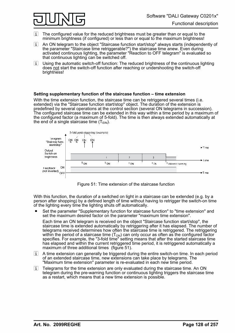
Art. No. 2099REGHE
i The configured value for the reduced brightness must be greater than or equal to theminimum brightness (if configured) or less than or equal to the maximum brightness!
i An ON telegram to the object "Staircase function start/stop" always starts (independently ofthe parameter "Staircase time retriggerable?") the staircase time anew. Even duringactivated continuous lighting, the parameter "Reaction to OFF telegram" is evaluated sothat continuous lighting can be switched off.
i Using the automatic switch-off function: The reduced brightness of the continuous lightingdoes not start the switch-off function after reaching or undershooting the switch-offbrightness!
Setting supplementary function of the staircase function – time extension With the time extension function, the staircase time can be retriggered several times (i.e.extended) via the "Staircase function start/stop" object. The duration of the extension ispredefined by several operations at the control section (several ON telegrams in succession).The configured staircase time can be extended in this way within a time period by a maximum ofthe configured factor (a maximum of 5-fold). The time is then always extended automatically atthe end of a single staircase time (TEIN).
Figure 51: Time extension of the staircase function
With this function, the duration of a switched on light in a staircase can be extended (e.g. by aperson after shopping) by a defined length of time without having to retrigger the switch-on timeof the lighting every time the lighting shuts off automatically.o Set the parameter "Supplementary function for staircase function" to "time extension" and
set the maximum desired factor on the parameter "maximum time extension".Each time an ON telegram is received on the object "Staircase function start/stop", thestaircase time is extended automatically by retriggering after it has elapsed. The number oftelegrams received determines how often the staircase time is retriggered. The retriggeringwithin the period of a staircase time (TON) can only occur as often as the configured factorspecifies. For example, the "3-fold time" setting means that after the started staircase timehas elapsed and within the current retriggered time period, it is retriggered automatically amaximum of three additional times (figure 51).
i A time extension can generally be triggered during the entire switch-on time. In each periodof an extended staircase time, new extensions can take place by telegrams. The"Maximum time extension" parameter is re-evaluated in each new time period.
i Telegrams for the time extension are only evaluated during the staircase time. An ONtelegram during the pre-warning function or continuous lighting triggers the staircase timeas a restart, which means that a new time extension is possible.
Page 128 of 257
Software "DALI Gateway C0201x"Functional description

Art. No. 2099REGHE
i If a time extension was configured as a supplementary function, the parameter "Staircasetime retriggerable ?" is preset to "No" because the retriggering takes place by the timeextension.
Setting supplementary function of the staircase function – time preset via the busWith the time preset via the bus, the configured staircase time can be multiplied by an8-bit factor received via the bus, thus it can be adapted dynamically. With this setting, the factoris derived from the object "staircase time factor". The possible factor value for setting thestaircase time is between 1…255.The entire staircase time arises as a product from factor (object value) and the configuredstaircase time as a basis as follows...Staircase time = (staircase time object value) x (staircase time parameter)Example:Object value "staircase time factor" = 5; parameter "staircase value" = 10s.-> set staircase time = 5 x 10s = 50 sAlternatively, the staircase function parameter can define whether the receipt of a new factoralso starts the staircase time of the staircase function at the same time. In this case, the object"Staircase function start/stop" is not necessary and the received factor value determines thestarting and stopping.o Set "supplementary function for staircase function" to "time preset via the bus" and set the
parameter "staircase function activatable via 'staircase time' object ?" to "No".The staircase time can be adapted dynamically by the "staircase time factor" object. Avalue "0" is interpreted as value "1". The staircase function is started and stoppedexclusively via the "staircase function start / stop" object.
o Set "supplementary function for staircase function" to "time preset via the bus" and set theparameter "staircase function activatable via 'staircase time' object ?" to "Yes".The staircase time can be adapted dynamically by the "staircase time factor" object. Inaddition, the staircase function is started with the new staircase time (the "staircasefunction start / stop" is not necessary) after receiving a new factor. A factor value "0" isinterpreted as an OFF telegram, whereby in this case, the configured reaction to an OFFtelegram is evaluated, too.A larger staircase with several floors is an example as an application for the time preset viathe bus with automatic starting of the staircase time. On each floor there is a push-buttonsensor that transmits a factor value to the staircase function. The higher the floor, thegreater the factor value transmitted so that the lighting stays switched on longer if thepassing through the staircase needs more time. When a person enters a staircase and apushbutton is pressed, the staircase time is now adjusted dynamically to the staircase timeand switches on the lighting at the same time, too.
i Setting "Staircase function activatable via"Staircase time" object ?" = "Yes":A factor > 0 received during a warning time triggers the staircase time independently of theparameter "staircase time retriggerable ?" always afterwards.
i After a reset (bus voltage return or ETS programming) the "staircase time factor" object isalways initialised with "1". The staircase function is not started automatically solely as theresult of this, however.
i The two supplementary functions "time extension" and "time preset via the bus" can onlybe configured alternatively.
Presetting behaviour of the staircase function after bus or mains voltage returnThe staircase function can be started automatically after bus or mains voltage return.The staircase function must be enabled.
Page 129 of 257
Software "DALI Gateway C0201x"Functional description

Art. No. 2099REGHE
o In the parameter node "Addressing -> Groups ... -> [x] Group" or "Addressing -> Singledevices ... -> [x] Electronic ballast", set the parameter "Behaviour after bus voltage return"to "Start staircase function".Immediately after bus or mains voltage return, the staircase time of the staircase function isstarted.
i The configured behaviour will only be executed, if no forced position on bus voltage returnis activated.
Page 130 of 257
Software "DALI Gateway C0201x"Functional description

Art. No. 2099REGHE
4.2.4.3.9 Operating hours counterThe operating hours counter determines the switch-on time of the DALI group or the singledevice. A group or an electronic ballast is actively on for the operating hours counter if thebrightness value is greater than "0", i.e. when the light is lit.The operating hours counter adds up the determined switch-on time accurately to the minute forthe DALI group or the single device in full hours respectively (figure 52). The totalled operatinghours are added in a 2-byte meter and stored permanently in the device. The current counterstatus can be transmitted cyclically to the bus by the "OHC value" communication object orwhen there is a change in an interval value.
Figure 52: Function of the operating hours counter (using the example of an up-counter)
In the as-delivered state, the operating hour values of all DALI groups and single devices of theGateway is "0". If the operating hours counter is not enabled in the configuration of a DALIgroup or a single device, no operating hours will be counted for the DALI group or single deviceconcerned. Once the operating hours counter is enabled, however, the operating hours will bedetermined and added up by the ETS immediately after commissioning the DALI Gateway.If the operating hours counter is subsequently disabled again in the parameters and theGateway is programmed with this disabling function, all operating hours previously counted forthe DALI group or the single device concerned will be deleted. When enabled again, the meterreading of the operating hours counter is always on "0 h".The operating hours values (full hours) stored in the device will not be lost in case of abus/mains voltage failure or by ETS programming. Any summed up operating minutes (full hournot yet reached) will be rejected in this case, however.After bus voltage return or after an ETS download, the Gateway passively updates the "OHCvalue" communication object in each DALI group or single device. The object value can be readout if the read-flag is set. The object value, depending on the configuration for the automatictransmission, is actively transmitted if necessary to the bus once the parameterised transmitdelay has elapsed after bus voltage return (see page 133-134).The operating hours counter detects any operation of the DALI groups or single devices by themanual operation, which means that switching on a channel also activates the counting ofoperating hours. In the same way, manual switch-off interrupts a counting operation.
Activating the operating hours countero Disable the "Operating hours counter" function in the parameter of the same name in the
parameter node "Addressing -> Groups ... -> [x] Group -> Operating hours counter" or"Addressing -> Single devices ... -> [x] Electronic ballast -> Operating hours counter" ("yes"setting).The operating hours counter is activated. The necessary parameters and communicationobjects are visible.
Page 131 of 257
Software "DALI Gateway C0201x"Functional description
Art. No. 2099REGHE
Deactivating the operating hours countero Disable the "Operating hours counter" function in the parameter of the same name in the
parameter node "Addressing -> Groups ... -> [x] Group -> Operating hours counter" or"Addressing -> Single devices ... -> [x] Electronic ballast -> Operating hours counter" ("no"setting).The operating hours counter is deactivated. No communication objects or parameters ofthe "Operating hours counter" function are visible.
i Deactivation of the operating hours counter and subsequent programming with the ETSresets the counter status to "0".
Setting the counter typeThe operating hours counter can optionally be configured as an up-counter or down-counter.Depending on this type of counter, a limit or start value can be set optionally, whereby, forexample, the operating time of a DALI group or a single device can be monitored by restrictingthe counter range.Up-counter:After activating the operating hours counter by enabling in the ETS or by restarting, theoperating hours are counted starting at "0". A maximum of 65,535 hours can be counted, afterthat the counter stops and signals a counter operation via the "OHC elapsed" object.A limiting value can be set optionally in the ETS or can be predefined via the communicationobject "OHC start/limiting value". In this case, the counter operation is signalled to the bus viathe "OHC elapsed" object if the limiting value is reached. The counter continues counting - if it isnot restarted - up to the maximum value 65,535 and then stops. Only a restart initiates a newcounting operation.Down-counter:After enabling the operating hours counter in the ETS, the counter status is on "0" and theGateway signals a counter operation for the DALI group or the single device concerned after theprogramming operation or after bus voltage return via the "OHC elapsed" object. Only after arestart is the down-counter set to the maximum value 65,535 the counting operation started.A starting value can be set optionally in the ETS or can be predefined via the communicationobject "OHC start/limiting value". If a start value is set, the down-counter is initialised with thisvalue instead of the maximum value after a restart. The meter then counts the start valuedownwards by the hour. When the down-counter reaches the value "0", the counter operation issignalled to the bus via the "OHC elapsed" and the counting is stopped. Only a restart initiates anew counting operation.Enable the "Operating hours counter" function in the parameter node "Addressing -> Groups ... -> [x] Group -> Operating hours counter" or "Addressing -> Single devices ... -> [x] Electronicballast -> Operating hours", in order for the required communication objects and parameters tobe visible.o Set the parameter "Counter type" to "Up-counter". Set the parameter "Start/limiting value
specification ?" to "yes, as received via object" or "yes, as parameter" if it is necessary tomonitor the limiting value. Otherwise, reset the parameter to "no". In the "yes, as specifiedin parameter" setting, specify the required limit value (1…65535 hrs).The meter counts the operating hours forwards starting from "0 h". If the monitoring of thelimiting value is activated, the Gateway transmits a "1" telegram via the object"OHC elapsed" as soon as the predefined limiting value is reached. Otherwise, the counteroperation is first transmitted when the maximum value 65,535 is reached.
o Set the parameter "Counter type" to "Down-counter". Set the parameter "Start/limiting valuespecification ?" to "yes, as received via object" or "yes, as parameter" if it is necessary tomonitor the start value. Otherwise, reset the parameter to "no". In the "yes, as specified inparameter" setting, specify the required start value (1…65535 hrs.).The meter counts the operating hours down to "0 h" after a restart. With a start valuepreset, the start value is counted down, otherwise the counting operation starts at themaximum value 65,535. The Gateway transmits a "1" telegram via the object"OHC elapsed" for the dimming channel concerned once the value "0" is reached.
Page 132 of 257
Software "DALI Gateway C0201x"Functional description

Art. No. 2099REGHE
i The value of the communication object "OHC elapsed" is stored permanently. The object isinitialised immediately with the value that was saved before bus voltage return or ETSprogramming. If an operating hours counter is in this case identified as elapsed, i.e. if theobject value is a "1", an additional telegram will be actively transmitted to the bus as soonas the parameterised transmit delay has elapsed after bus voltage return. If the counter hasnot yet elapsed (object value "0"), no telegram is transmitted on return of bus voltage orafter an ETS programming operation.
i With a limiting or start value preset via object: The values received via the object are firstvalidly accepted and permanently saved internally after a restart of the operating hourscounter. The object is initialised immediately with the value that was last saved before busvoltage return or ETS programming. The values received will be lost in the case of a busvoltage failure or by an ETS download if no counter restart was executed before. For thisreason, when specifying a new start or limiting value it is advisable to always execute acounter restart afterwards as well.A standard value of 65,535 is predefined provided that no limiting value or start value hasbeen received yet via the object. The values received and stored via the object are reset tothe standard value if the operating hours counter is deactivated in the parameters of theETS and an ETS programming operation is being performed.
i With a limiting or start value predefined via object: If the start or limiting value is predefinedwith "0", the actuator will ignore a counter restart to avoid an undesired reset(e.g. in site operation -> hours already counted by manual operation).
i If the counter direction of an operating hours counter is reversed by reconfiguration in theETS, a restart of the meter should always be performed after programming the gateway sothat the meter is reinitialised.
Restarting the operating hours counterThe counter status of the operating hours can be reset at any time by the communication object"OHC restart". The polarity of the restart telegram is predefined: "1" = restart / "0" = no reaction.o Describe the communication object "OHC restart" as "1".
In the up-counter the meter is initialised with the value "0" after a restart and in the down-counter initialised with the start value. If no start value was configured or predefined by theobject, the start value is preset to 65,535.During every counter restart, the initialised meter reading is transmitted actively to the bus.After a restart, the signal of a counter operation is also reset. At the same time, a "0"telegram is transmitted to the bus via the object "OHC elapsed". In addition, the limiting orstart value is initialised.
i If a new limiting or start value was predefined via the communication object, a counterrestart should always be performed afterwards, too. Otherwise, the values received will belost in the case of a bus voltage failure or by an ETS download.
i If the communication object "OHC start/limiting value" was described with "0" (eithermanually by the user or after a device reset), there are different behaviours after a restartdepending on the principle of the value specification...Preset as parameter:The counter elapses immediately after a counter restart.Preset via object:A counter restart will be ignored to avoid an undesired reset (e.g. after installation of thedevices with hours already being counted by manual operation). A limiting or start valuegreater than "0" must be predefined in order to perform the restart.
Setting the transmission behaviourThe current value of the operating hours counter is always tracked in the communication object"OHC value". After bus voltage return or after an ETS programming operation, the Gatewaypassively updates the "OHC value" communication object in each DALI group or single device.
Page 133 of 257
Software "DALI Gateway C0201x"Functional description

Art. No. 2099REGHE
The object value can be read out if the read-flag is set.In addition, the transmission behaviour of this communication object can be set.Enable the "Operating hours counter" function in the parameter node "Addressing -> Groups ... -> [x] Group -> Operating hours counter" or "Addressing -> Single devices ... -> [x] Electronicballast -> Operating hours", in order for the required communication objects and parameters tobe visible.o Set the parameter "Automatic transmission of counting value" to "After change by interval
value". Configure the "Counting value interval (1…65535 hrs.)" to the desired value.The meter reading is transmitted to the bus as soon as it changes by the predefinedcounting value interval. After bus voltage return or after ETS programming operation, theobject value is transmitted automatically after "Delay after bus voltage return" has elapsedif the current counter status or a multiple of this corresponds to the counting value interval.A counter status "0" is always transmitted in this case.
o Set the parameter "Automatic transmission of counting value" to "Cyclical".The counter value is transmitted cyclically. The cycle time is defined independent of thechannel on the parameter page "Status and feedback". After bus voltage return or ETSprogramming, the counter status is transmitted to the KNX after the configured cycle timehas elapsed.
Page 134 of 257
Software "DALI Gateway C0201x"Functional description
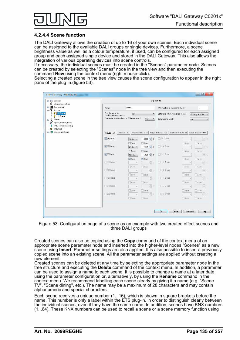
Art. No. 2099REGHE
4.2.4.4 Scene functionThe DALI Gateway allows the creation of up to 16 of your own scenes. Each individual scenecan be assigned to the available DALI groups or single devices. Furthermore, a scenebrightness value as well as a colour temperature, if used, can be configured for each assignedgroup and each assigned single device and stored in the DALI Gateway. This also allows theintegration of various operating devices into scene controls.If necessary, the individual scenes must be created in the "Scenes" parameter node. Scenescan be created by selecting the "Scenes" node in the tree view and then executing thecommand New using the context menu (right mouse-click).Selecting a created scene in the tree view causes the scene configuration to appear in the rightpane of the plug-in.(figure 53).
Figure 53: Configuration page of a scene as an example with two created effect scenes andthree DALI groups
Created scenes can also be copied using the Copy command of the context menu of anappropriate scene parameter node and inserted into the higher-level nodes "Scenes" as a newscene using Insert. Parameter settings are also applied. It is also possible to insert a previouslycopied scene into an existing scene. All the parameter settings are applied without creating anew element.Created scenes can be deleted at any time by selecting the appropriate parameter node in thetree structure and executing the Delete command of the context menu. In addition, a parametercan be used to assign a name to each scene. It is possible to change a name at a later dateusing the parameter configuration or, alternatively, by using the Rename command in thecontext menu. We recommend labelling each scene clearly by giving it a name (e.g. "SceneTV", "Scene dining", etc.). The name may be a maximum of 28 characters and may containalphanumeric and special characters.Each scene receives a unique number (1...16), which is shown in square brackets before thename. This number is only a label within the ETS plug-in, in order to distinguish clearly betweenthe individual scenes, even if they have the same name. In addition, scenes have KNX numbers(1...64). These KNX numbers can be used to recall a scene or a scene memory function using
Page 135 of 257
Software "DALI Gateway C0201x"Functional description
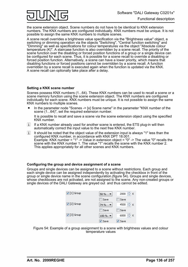
Art. No. 2099REGHE
the scene extension object. Scene numbers do not have to be identical to KNX extensionnumbers. The KNX numbers are configured individually. KNX numbers must be unique. It is notpossible to assign the same KNX numbers to multiple scenes.A scene recall overrides a brightness value specification via the "Brightness value" object, aswitching or dimming operation via the objects "Switching", "Central function switching" and"Dimming" as well as specifications for colour temperatures via the object "Absolute colourtemperature (K)". A staircase function is also overridden by a scene recall. The priority of thescene function over the disabling or forced position functions of a group or a single device canbe configured for each scene. Thus, it is possible for a scene recall to override a disabling orforced position function. Alternatively, a scene can have a lower priority, which means thatdisabling functions or forced positions cannot be overridden by a scene recall. A functionoverridden by a scene recall is executed again when the function is updated via the KNX.A scene recall can optionally take place after a delay.
Setting a KNX scene number Scenes possess KNX numbers (1...64). These KNX numbers can be used to recall a scene or ascene memory function using the scene extension object. The KNX numbers are configuredindividually for each scene. KNX numbers must be unique. It is not possible to assign the sameKNX numbers to multiple scenes.o In the parameter node "Scenes -> [x] Scene name" in the parameter "KNX number of the
scene (1...64)", set the required extension number.It is possible to recall and save a scene via the scene extension object using the specifiedKNX number.
i If a KNX number already used for another scene is entered, the ETS plug-in will thenautomatically correct the input value to the next free KNX number.
i It should be noted that the object value of the extension input is always "1" less than theconfigured KNX number, in accordance with KNX DPT 18.001.Example: KNX number = "1" -> Value in extension object = "0" -> The value "0" recalls thescene with the KNX number 1. The value "1" recalls the scene with the KNX number 2.This applies appropriately for all other scenes and KNX numbers.
Configuring the group and device assignment of a sceneGroups and single devices can be assigned to a scene without restrictions. Each group andeach single device can be assigned independently by activating the checkbox in front of thegroup or single device name in the scene configuration.(figure 54). Groups and single devices,whose checkboxes are not activated, are not assigned to the scene. Any non-created groups orsingle devices of the DALI Gateway are greyed out and thus cannot be edited.
Figure 54: Example of a group assignment to a scene with brightness values and colourtemperature values
Page 136 of 257
Software "DALI Gateway C0201x"Functional description

Art. No. 2099REGHE
For reasons of clarity, all the available groups (1...32) and single devices (1...64) - irrespectiveof the configured addressing type - are split up into various pages in the scene function window,each of which can be displayed separately. 16 groups or single devices are available on anygiven page. Pressing the buttons "Groups...", "Single devices..." in the scene configurationwindow changes between the page views.Scenes can also be used for a master control (broadcast). Only one brightness value andoptionally one colour temperature value can ever be assigned to each scene.o Activate the checkbox of the DALI groups and single devices, which are to be assigned to
the selected scene.The activated groups and single devices are assigned to the scene. The parameters of thescene brightness value and - if the colour temperature control is used - scene colourtemperature value are enabled including the parameter for the memory functions.
i DALI groups or single devices integrated in centrally supplied emergency lighting operationcannot be assigned to any scene! Assignments to scenes are lost if the integration ofgroups or devices takes place later in emergency operation. In these cases, the ETS plug-in warns of losing assignments.
Setting scene brightness values and colour temperature valuesFor each DALI group integrated in a scene, for each integrated single device and for eachscene, it is necessary to specify which brightness value is to be set when a scene is recalled.When using the tunable white function for DALI operating devices, which support the "ColourControl" (DALI Device Type 8) device type, a colour temperature can also optionally be definedfor each assigned group or single device.A group or a single device must be assigned to a scene.o In the parameter node "Scenes -> [x] Scene name", specify the necessary scene
brightness value for each DALI group assigned to the scene and each assigned singledevice.During a scene recall, the appropriate configured brightness value is set on the operatingdevices. In the setting "---" the brightness value of the group or single device remainsunchanged when recalling the scene.
o When using the colour temperature control: In the parameter node "Scenes -> [x] Scenename", specify the necessary scene colour temperature value for each DALI groupassigned to the scene and each assigned single device. In the setting "---" the colourtemperature value of the group or single device remains unchanged when recalling thescene.During a scene recall, the appropriate configured colour temperature is set on the operatingdevices. It should be noted that a colour temperature specified in the scene is only visuallyeffective in the DALI lights if the group or single device is switched on, too.Even if groups or single devices are switched off, colour temperature changes are trackedinternally in the device when recalling a scene. On switching on a group or single deviceafter a scene recall, the colour temperature most recently recalled according to the scene ispreset in the DALI lights.
i The configured brightness values and colour temperature values are adopted in the DALIGateway during programming with the ETS only if the parameter "Overwrite scene valuesduring ETS download ?" is set to "yes".
i The selection of the scene brightness value and scene colour temperature value isrestricted in the ETS plug-in by the configured minimum and maximum values.
i The parameters for the colour temperature are only available if the tunable white lights areintegrated under "General". If the colour temperature control is used globally, the plug-inalways displays parameters for the colour temperature for all groups and single devices inall scenes, too. This is displayed even if no colour temperature control at all is provided inthe groups or single devices (e.g. in the case of DALI device types that do not even allowany colour temperature control). In such cases, the colour temperature specifications in thescenes are ineffective.
Page 137 of 257
Software "DALI Gateway C0201x"Functional description
Art. No. 2099REGHE
i During DALI commissioning, it is possible to assign multiple identical DALI operatingdevices to different groups (multiple assignment: e.g. Electronic ballast 1 is located inGroup A and Group B). If groups (e.g. A & B) have now been assigned to a scene andthese groups contain the same operating devices (e.g. electronic ballast 1), then there willbe a conflict on account of the differing scene brightness values or scene colourtemperature values. In this case, the operating devices assigned multiple times are set tothe value of the group with the highest number.
Presetting the storage behaviour for the scene functionThe current brightness values of all the DALI groups and single devices assigned to as scenecan be saved using the scene extension using when a save telegram is received. In so doing,the brightness values to be saved can be influenced by all the functions of the individual groupsand devices (e.g. switching, dimming, manual operation) before saving. When using the tunablewhite function for DALI operating devices, which support the "Colour Control" (DALI DeviceType 8) device type, the memory function of the colour temperature can also optionally betriggered for each assigned group or single device.A group or a single device must be assigned to a scene.o In the parameter node "Scenes -> [x] Scene name" activate the "Save" checkbox for the
DALI groups and single devices below the brightness value, which are to react to thememory function.The memory function of the brightness is activated for the DALI group or single deviceaffected. The current brightness value is stored internally in the scene via the extensionobject on receipt of a storage telegram.
o In the parameter node "Scenes -> [x] Scene name" activate the "Save" checkbox for theDALI groups and single devices below the colour temperature value, which are to react tothe memory function.The memory function of the colour temperature is activated for the DALI group or singledevice affected. The current colour temperature is stored internally in the scene via theextension object on receipt of a storage telegram.
o In the parameter node "Scenes -> [x] Scene name" deactivate the "Save" checkbox for theDALI groups and single devices below the brightness value, which are not to react to thememory function.The memory function of the brightness is deactivated for the DALI group or single deviceaffected. A storage telegram received via the extension object will be rejected based on thebrightness. During a scene recall, the brightness permanently defined in the scene is thenrecalled.
o In the parameter node "Scenes -> [x] Scene name" deactivate the "Save" checkbox for theDALI groups and single devices below the colour temperature value, which are not to reactto the memory function.The memory function of the colour temperature is deactivated for the DALI group or singledevice affected. A storage telegram received via the extension object will be rejected basedon the colour temperature. During a scene recall, the colour temperature permanentlydefined in the scene is then recalled.
i If the brightness or colour temperature of a scene is configured to "---" (no change), thememory function of the scene values concerned can generally not be executed. Thecheckbox of the memory function is then not selectable in the ETS plug-in.
i During a save operation, scene values are saved to internal non-volatile memory in theDALI Gateway, thus overwriting the value of a group or single device most recentlyprogrammed by the ETS. The configured brightness values and colour temperature valuesin the ETS are adopted again in the DALI Gateway during programming with the ETS onlyif the parameter "Overwrite scene values during ETS download ?" is set to "yes".
Page 138 of 257
Software "DALI Gateway C0201x"Functional description

Art. No. 2099REGHE
i Irrespective of the set priority for the entire scene, no new scene values are ever saved ifdisabling or a forced position is active for individual groups or devices.
Setting the scene priority The priority of the scene function over the disabling or forced position functions of a group or asingle device can be configured for each scene. Thus, it is possible for a scene recall to overridea disabling or forced position function. Alternatively, a scene can have a lower priority, whichmeans that disabling functions or forced positions cannot be overridden by a scene recall.The scene priority can be configured separately for each created scene.o In the parameter node "Scenes -> [x] Scene name", configure the parameter "Priority,
scene to be disabled/forced position" to "low".The scene has a lower priority to the supplementary functions of the assigned groups orthe assigned single devices. It is not possible to call up or save a scene if a supplementaryfunctions is only activated for one group or one single device.
o In the parameter node "Scenes -> [x] Scene name", configure the parameter "Priority,scene to be disabled/forced position" to "high".The scene has a higher priority to the supplementary functions of the assigned groups orthe assigned single devices. Scenes are only ever called-up or saved when a sceneextension unit is received.
i Irrespective of the set priority for the entire scene, no new scene values are ever saved ifdisabling or a forced position is active for individual groups or devices.
i In the "Tracked brightness value" setting at the end of disabling/forced position: At the endof the supplementary functions, a scene recall received during the function will not betracked.
i In the "Priority = High" setting: A scene recall does not statically lock the lower-levelfunctions of a group or a single device. The higher priority solely specifies that the scenebrightness value is set at the moment of the scene recall and the previously specifiedbrightness value is overridden. After scene recall, it is possible that the scene brightnessvalue will be changed by other functions of the Gateway (e.g. on terminating an additionalfunction or by switching or dimming).
i Scenes can also be included in effect steps. In this case, the scene priority is not evaluatedwhen an effect is recalled. The configured priority of the appropriate effect is of moreimportance.
Setting the ETS programming behaviour for the scene functionDuring storage of a scene, the scene values are stored internally to non-volatile memory in thedevice. To prevent the stored values from being replaced during ETS programming of theapplication or of the parameters by the originally programmed scene brightness values or scenecolour temperature values, the DALI Gateway can inhibit overwriting of the scene values. As analternative, the original values can be reloaded into the device during each programming run ofthe ETS.The ETS programming behaviour can be configured separately for each scene.o In the parameter node "Scenes -> [x] Scene name", set the parameter "Overwrite scene
values during ETS download" to "yes".During each ETS programming operation of the application program or of the parameters,the scene values configured in the ETS will be programmed into the Gateway. Scenevalues stored in the device by means of a storage function will be overwritten, if any.
o In the parameter node "Scenes -> [x] Scene name", set the parameter "Overwrite scenevalues during ETS download" to "no".
Page 139 of 257
Software "DALI Gateway C0201x"Functional description

Art. No. 2099REGHE
Scene values stored in the device with a storage function will be maintained. If no scenevalues have been stored, the brightness values and colour temperature values lastprogrammed in the ETS remain valid.
i During first commissioning of the Gateway, this parameter should be set to "yes" so thatthe scenes are initialised with valid scene values.
Presetting the recall delay for the scene functionEach scene recall can optionally also be evaluated after a delay. With this feature, dynamicalscene sequences can, for example, be configured if several actuators or Gateways arecombined with cyclical scene telegrams.The scene recall delay can be configured separately for each created scene.o In the parameter node "Scenes -> [x] Scene name", set the parameter "Delay scene
recall?" to "yes". Configure the delay time.The delay time is activated. The delay only influences the scene recall of the appropriatescene. The delay time is started on arrival of a recall telegram. The corresponding scenewill be recalled and the brightness and colour temperature value set to the respectivescene position value only after this time has elapsed.
o In the parameter node "Scenes -> [x] Scene name", set the parameter "Delay scenerecall?" to "no".The delay time is deactivated. A scene recall is carried out without a delay immediatelyafter the receipt of a scene recall telegram.
i Each scene recall telegram restarts the delay time and retriggers it. If a new scene recalltelegram is received while a delay is active (scene recall not yet executed), the old (and notyet recalled scene) will be rejected and only the scene last received executed.
i The scene recall delay has no influence on the storage of scene values. A scene storagetelegram within a scene recall delay terminates the delay and thus the scene recall.
i In case of bus or mains voltage failure, all time functions will be stopped. Therefore, allscene recalls that are still in the delay stage will be aborted. A scene recall received shortlybefore bus or mains voltage failure will then be lost if the corresponding delay has not yetelapsed. A delayed scene recall will also be completely aborted for the affected groups orsingle devices in the case of a function with a higher priority (e.g. manual operation, forcedposition function, disable function).
i Scenes can also be included in effect steps. In this case, the recall delay set for the sceneis not effective when an effect is recalled. The configured time sequence of the effect is ofmore importance.
Setting the dimming behaviour when recalling a sceneIn the scene configuration, it is possible to define whether the scene brightness values andscene colour temperature values for the assigned groups or single devices jump instantly ordim. A scene recall can therefore be executed independently of the set dimming behaviour.The behaviour during a scene recall can be configured separately for each scene.o In the parameter node "Scenes -> [x] Scene name", set the parameter "Behaviour on scene
recall" to "Jump".The values of the scene concerned are jumped to instantly during a recall.
o In the parameter node "Scenes -> [x] Scene name", set the parameter "Behaviour on scenerecall" to "Dim to...". "Dim to...". At the same time, define the time required to dim to thescene values.
Page 140 of 257
Software "DALI Gateway C0201x"Functional description

Art. No. 2099REGHE
The values of the scene concerned are dimmed to during a recall. The dim fading isactivated The time in the parameter selection defines the duration of the dimmingprocedure required to reach the values. The brightness values and colour temperaturevalues of a group or a single device at which the dimming starts has no significance. Thus,the dimming procedure in case of a scene recall always requires the exact predefined timefor all groups and single devices of the scene.
i Any DALI operating devices included in the scene (through groups or as a single device)react simultaneously, because addressing takes place on the DALI-side using scenecommands (Multicast), which the Gateway programs into the operating device duringinitialisation, according to the scene configuration in the ETS plug-in.
i The configured dimming time for the dim fading of the scene function may deviate from thestandard dimming behaviour of a group or a single device. The DALI Gateway alwaysworks with a standard fading time of 0.7 seconds. This value is automatically programmedinto DALI operating devices during initialisation. Directly after scene recall, the Gatewayreprograms all the assigned DALI operating devices to the dimming time of the scene. Afterrecalling the scene, the Gateway immediately reprograms the fading time back to theoriginal value. This reprogramming takes place separately for each group and single deviceintegrated into the scene in sequence via the DALI cable.
i Scenes can also be included in effect steps. In this case, the dimming behaviour set for thescene is not effective when an effect is recalled. The configured dimming behaviour of aneffect is of more importance.
Page 141 of 257
Software "DALI Gateway C0201x"Functional description
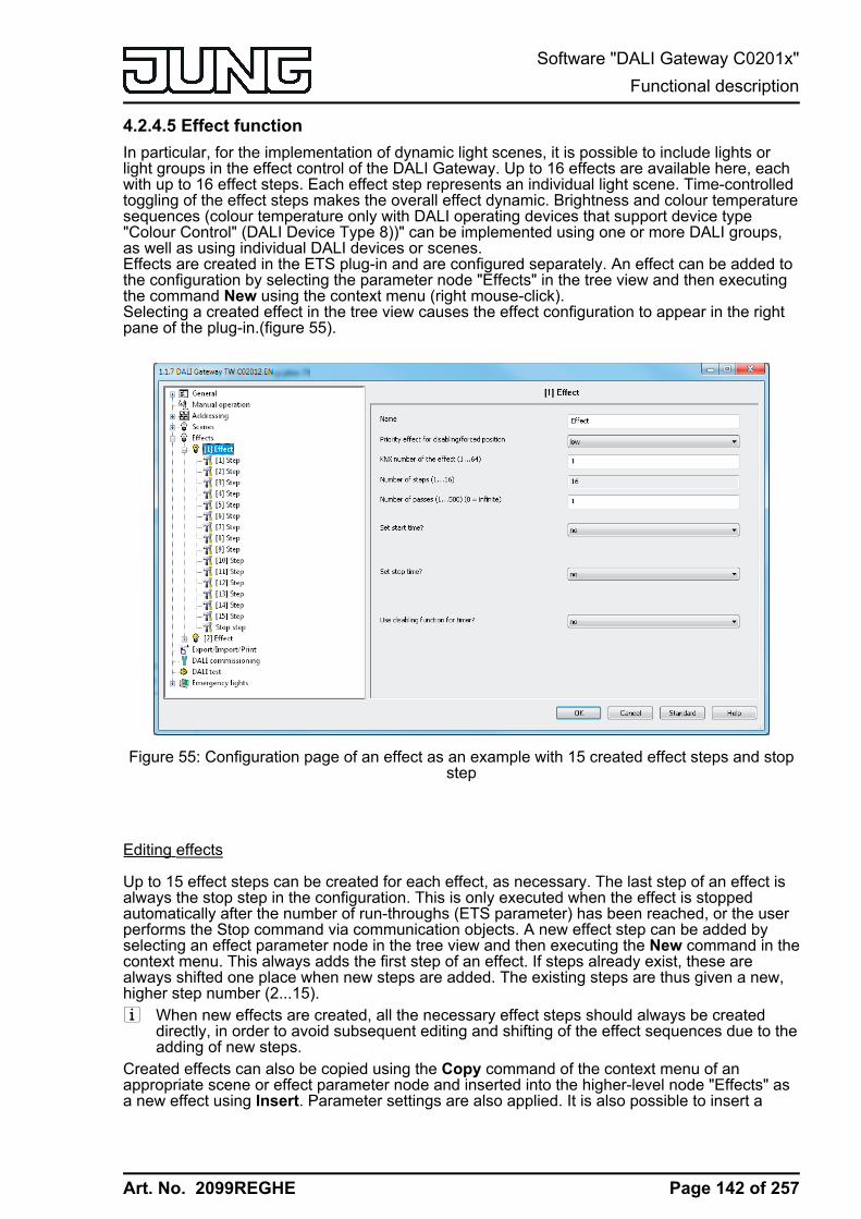
Art. No. 2099REGHE
4.2.4.5 Effect functionIn particular, for the implementation of dynamic light scenes, it is possible to include lights orlight groups in the effect control of the DALI Gateway. Up to 16 effects are available here, eachwith up to 16 effect steps. Each effect step represents an individual light scene. Time-controlledtoggling of the effect steps makes the overall effect dynamic. Brightness and colour temperaturesequences (colour temperature only with DALI operating devices that support device type"Colour Control" (DALI Device Type 8))" can be implemented using one or more DALI groups,as well as using individual DALI devices or scenes.Effects are created in the ETS plug-in and are configured separately. An effect can be added tothe configuration by selecting the parameter node "Effects" in the tree view and then executingthe command New using the context menu (right mouse-click).Selecting a created effect in the tree view causes the effect configuration to appear in the rightpane of the plug-in.(figure 55).
Figure 55: Configuration page of an effect as an example with 15 created effect steps and stopstep
Editing effects
Up to 15 effect steps can be created for each effect, as necessary. The last step of an effect isalways the stop step in the configuration. This is only executed when the effect is stoppedautomatically after the number of run-throughs (ETS parameter) has been reached, or the userperforms the Stop command via communication objects. A new effect step can be added byselecting an effect parameter node in the tree view and then executing the New command in thecontext menu. This always adds the first step of an effect. If steps already exist, these arealways shifted one place when new steps are added. The existing steps are thus given a new,higher step number (2...15). i When new effects are created, all the necessary effect steps should always be created
directly, in order to avoid subsequent editing and shifting of the effect sequences due to theadding of new steps.
Created effects can also be copied using the Copy command of the context menu of anappropriate scene or effect parameter node and inserted into the higher-level node "Effects" asa new effect using Insert. Parameter settings are also applied. It is also possible to insert a
Page 142 of 257
Software "DALI Gateway C0201x"Functional description
Art. No. 2099REGHE
previously copied effect into an existing effect. All the parameter settings are applied withoutcreating a new element.Effect steps can only be copied and inserted into existing steps. This completely transfers theconfiguration of the copied step into another step. This function can be used, for example, totransport existing step configurations into other steps, after new steps have been added,thereby changing the sequence of the light scene.Created effects and effect steps can be deleted at any time by selecting the appropriateparameter node in the tree structure and executing the Delete command of the context menu. Inaddition, a parameter can be used to assign a name to each effect. It is possible to change aname at a later date using the parameter configuration or, alternatively, by using the Renamecommand in the context menu. We recommend labelling each effect clearly by giving it a name(e.g. "Effect window", "Effect entrance area", etc.). The name may be a maximum of 28characters and may contain alphanumeric and special characters.Each effect receives a unique number (1...16), which is shown in square brackets before thename. This number is only a label within the ETS plug-in, in order to distinguish clearly betweenthe individual effects, even if they have the same name. In addition, effects possess KNXnumbers (1...64). These KNX numbers can be used to start and stop the effects using theextension object. Effect numbers do not have to be identical to KNX extension numbers. TheKNX numbers are configured individually.KNX numbers must be unique. It is not possible to assign the same KNX numbers to multipleeffects.In the case of effect steps, the step number (1...15) is displayed in square brackets. This labelsthe step sequence of an effect run-through directly.
Starting and stopping effects (effect run-through)
Effect steps can control DALI groups, single devices and scenes. As soon as it is started, aneffect runs "in the background". Each new effect step overrides the previous effect step or themost recently specified brightness and colour temperature state of an integrated DALI group oran assigned single device. In contrast to the control of groups and devices via the objects"Switching", "Dimming", "Brightness value", "Absolute colour temperature" and "Central functionfor groups and devices", effects always have the same priority. The last presetting determinesthe brightness and colour temperature value.With regard to the time sequences (time between effect steps, dimming behaviour), an effectonly ever works with the parameters of the effect steps. Parameters of the DALI groups,individual devices or the scenes are irrelevant for the effect function. To ensure that timefunctions of the groups and devices (e.g. staircase function, time delays) and the effect functiondo not influence each other, parallel operation of these functions, i.e. the execution of an effectand control using group or device functions, should be avoided if possible.An effect always starts at effect step 1. The steps are processed in sequence, according to theirnumber. Once all the brightness values and colour temperature values of an effect step havebeen set, the effect controller waits for the set "Delay until the next step". Then the next step isrecalled. An effect run-through corresponds to calling up all the steps created in the effect. Thenumber of run-throughs can be specified individually between 1...500 using a parameter. Aneffect stops automatically when the configured number of run-throughs has been reached.Otherwise the effect starts again with the first step after processing of the last effect step.Alternatively, an effect can also be started manually using communication objects and stoppedat any time. A stop command terminates the effect immediately after the processing of thecurrent step and subsequent execution of the stop step, without recalling other effect steps orwaiting for delay times (figure 57). There are separate 1-bit objects (1 = Start effect / 0 = Stopeffect) as well as a shared 1-byte extension object available manual starting and stopping ofeffects.When an effect is stopped, the stop step is always executed. This makes it possible to set adefined lighting state. The stop step is not executed explicitly between multiple effect run-throughs.
Page 143 of 257
Software "DALI Gateway C0201x"Functional description

Art. No. 2099REGHE
start
step 1 step 2
run-through 1 run-through 2
step 3 step 3step 1 step 2 stop
t
Figure 56: Example of an effect sequence with automatic stop(here: 3 effect steps, 2 run-throughs)
start stop
t
step 1 step 2 step 3 step 1 step 2 stop
run-through 1 run-through 2 (shorten)
Figure 57: Example of an effect sequence with manual stop(here: 3 effect steps, run-through 2 is stopped early)
i Retriggering of an effect (multiple starting) shows no reaction. The effect continuesnormally. An effect must first be stopped, in order to restart it in a defined manner at Step 1.
i It is possible to run through multiple effects simultaneously. If the same groups, singledevices or scenes are integrated into effects running simultaneously, then the effectsinfluence each other. In order to achieve a tidy, fault-free effect run-through, always try toavoid running through effects with the same assignments simultaneously.
The priority of the effect function over the disabling or forced position functions of a group or asingle device can be configured separately for each effect. Thus, it is possible for an effect recallto override a disabling or forced position function. An effect can have a lower priority, meaningthat disabling functions or forced positions cannot be overridden by a effect recall.
Setting a KNX effect number Just like scenes, effects possess KNX numbers (1...64). These KNX numbers can be used tostart and also stop individual effects using the extension object of the effect function. The KNXnumbers are configured individually for each effect. KNX numbers must be unique. It is notpossible to assign the same KNX numbers to multiple effects.The structure of the telegram value for the effect extension is orientated to the KNX DPT18.001, which is also used in the scene extension (figure 58).
Page 144 of 257
Software "DALI Gateway C0201x"Functional description
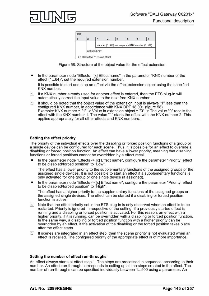
Art. No. 2099REGHE
bits
number (0...63), corresponds KNX number (1...64)
not used (“0“)
7 6 5 4 3 2 1 0
0 = start effect / 1 = stop effect
Figure 58: Structure of the object value for the effect extension
o In the parameter node "Effects - [x] Effect name" in the parameter "KNX number of theeffect (1...64)", set the required extension number.It is possible to start and stop an effect via the effect extension object using the specifiedKNX number.
i If a KNX number already used for another effect is entered, then the ETS plug-in willautomatically correct the input value to the next free KNX number.
i It should be noted that the object value of the extension input is always "1" less than theconfigured KNX number, in accordance with KNX DPT 18.001 (figure 58).Example: KNX number = "1" -> Value in extension object = "0" -> The value "0" recalls theeffect with the KNX number 1. The value "1" starts the effect with the KNX number 2. Thisapplies appropriately for all other effects and KNX numbers.
Setting the effect priority The priority of the individual effects over the disabling or forced position functions of a group ora single device can be configured for each scene. Thus, it is possible for an effect to override adisabling or forced position function. An effect can have a lower priority, meaning that disablingfunctions or forced positions cannot be overridden by a effect recall.o In the parameter node "Effects -> [x] Effect name", configure the parameter "Priority, effect
to be disabled/forced position" to "Low".The effect has a lower priority to the supplementary functions of the assigned groups or theassigned single devices. It is not possible to start an effect if a supplementary functions isonly activated for one group or one single device (if assigned).
o In the parameter node "Effects -> [x] Effect name", configure the parameter "Priority, effectto be disabled/forced position" to "High".The effect has a higher priority to the supplementary functions of the assigned groups orthe assigned single devices. The effect can be started if a disabling or forced positionfunction is active.
i Note that the effect priority set in the ETS plug-in is only observed when an effect is to berestarted. Priority is ignored - irrespective of the setting- if a previously started effect isrunning and a disabling or forced position is activated. For this reason, an effect with ahigher priority, if it is running, can be overridden with a disabling or forced position function.In the same way, a disabling or forced position function with a higher priority can beoverridden by an effect, if the activation of the disabling or the forced position takes placeafter the effect starts.
i If scenes are integrated in an effect step, then the scene priority is not evaluated when aneffect is recalled. The configured priority of the appropriate effect is of more importance.
Setting the number of effect run-throughs An effect always starts at effect step 1. The steps are processed in sequence, according to theirnumber. An effect run-through corresponds to calling up all the steps created in the effect. Thenumber of run-throughs can be specified individually between 1...500 using a parameter. An
Page 145 of 257
Software "DALI Gateway C0201x"Functional description

Art. No. 2099REGHE
effect stops automatically when the configured number of run-throughs has been reached.Otherwise the effect starts again with the first step after processing of the last effect step.o In the parameter node "Effects -> [x] Effect name", set the parameter "Number of run-
throughs" to the desired value (0...500).The effect repeats the set number of times. Then the effect stops automatically. In the "0"setting, the effect repeats cyclically, until a manual Stop command is received via thecommunication objects.
i A manual stop command via the communication objects terminates the effect immediatelyafter the processing of the current step and subsequent execution of the stop step, withoutrecalling other effect steps or waiting for delay times.
Configuring the group and device assignment of an effect stepGroups and single devices can be assigned to an effect step without restrictions. In addition, it ispossible to assign created scenes. Each group, each single device and each scene can beassigned independently by activating the checkbox in front of the group or single device nameor the scene name in the configuration of the effect steps.(figure 59). Groups, single devicesand scenes, whose checkboxes are not activated, are not assigned to the effect step. Any non-created groups, single devices or scenes of the DALI Gateway are greyed out and thus cannotbe edited.
Figure 59: Example of a group assignment to an effect step
For reasons of clarity, all the available groups (1...32) and single devices (1...64) - irrespectiveof the configured addressing type - as well as the scenes (1...16) are split up into various pagesin the window of an effect step, each of which can be displayed separately. 16 groups or singledevices are available on any given page. Scenes also have their own page. Pressing thebuttons "Groups...", "Single devices..." or "Scenes 1-16" in the configuration window of an effectstep changes between the page views.Effects can also be used for master control (broadcast). Only one brightness value and onecolour temperature value is ever assigned to each effect step.o Activate the checkbox of the DALI groups, single devices and scenes, which are to be
assigned to the selected effect step.The activated groups, single devices and scenes are assigned to the effect step. Theparameters of the brightness values and - if the colour temperature control is used - colourtemperature values are enabled.
Page 146 of 257
Software "DALI Gateway C0201x"Functional description
Art. No. 2099REGHE
i Assigned single devices are contacted in turn by the effect controller, because the devicesare addressed individually using their short address. This slows down processing of aneffect step. In addition, this influences the processing time of an effect step, if the dimmingbehaviour allows for dimming times other than the standard (0.7 seconds). The moregroups or single devices are assigned to an effect step, the slower the effect step editingwill be. The "Delay until next step" is only started when the last assignment of an effect stephas been processed.When a scene is recalled, the slowing effect from the addressing type does not noticeablyoccur. For this reason, we recommend integrating devices - if at all possible - into scenesand assigning them to the effect controller.Only groups, single devices or scenes, whose brightness or colour temperature are to bechanged by an effect step, should ever be assigned to that step.
i If several identical DALI operating devices are integrated into an effect step, for example,due to redundant integration via groups and scenes, the brightness and colour temperaturecommands are evaluated and set using a fixed priority. The group brightness/colourtemperature value specified in an effect step has the highest priority and thus prevails overvalues of single devices and scenes. The brightness/colour temperature values of singledevices have medium priority and prevail over scene values. Scene values have the lowestpriority.
i It is possible to run through multiple effects simultaneously. If the same groups, singledevices or scenes are integrated into effects running simultaneously, then the effectsinfluence each other. In order to achieve a tidy, fault-free effect run-through, always try toavoid running through effects with the same assignments simultaneously.
i DALI groups or single devices integrated in centrally supplied emergency lighting operationcannot be used in effects! Assignments to effect steps are lost if the integration of groups ordevices takes place later in emergency operation. In these cases, the ETS plug-in warns oflosing assignments.
Setting brightness values and colour temperatures for effect stepsFor each DALI group integrated in an effect step and for each integrated single device, it isnecessary to specify which brightness value is to be set when the effect step is recalled. Whenusing the tunable white function for DALI operating devices, which support the "Colour Control"(DALI Device Type 8) device type, a colour temperature can also optionally be defined for eachassigned group or single device.A group, a single device or a scene must be assigned to an effect step.o In the parameter node "Effects -> [x] Effect name -> [y] Step" (x = 1...16 / y = 1...15),
specify the necessary brightness value for each assigned DALI group and for eachassigned single device. In the setting "---" the brightness value of the group or single deviceremains unchanged when recalling the effect step.During a recall of the effect step, the appropriate configured brightness value is set on theoperating devices.
o When using the colour temperature control: In the parameter node "effect -> [x] effect name-> [y] step" (x = 1...16 / y = 1...15), specify the necessary scene colour temperature valuefor each DALI group assigned to the scene and for each assigned single device. In thesetting "---" the colour temperature of the group or single device remains unchanged whenrecalling the effect step.During a recall of the effect step, the appropriate configured colour temperature is set onthe operating devices. It should be noted that a specified colour temperature is only visuallyeffective in the DALI lights if the group or single device is switched on, too.Even if groups or single devices are switched off, colour temperature changes are trackedinternally in the device during the effect control. On switching on a group or single devicewhile an effect is running, the colour temperature most recently recalled according to thecurrent effect step is preset in the DALI lights.
i The selection of the brightness values and colour temperature values is restricted in theETS plug-in by the configured minimum and maximum values.
Page 147 of 257
Software "DALI Gateway C0201x"Functional description

Art. No. 2099REGHE
i The parameters for the colour temperature are only available if the tunable white lights areintegrated under "General". If the colour temperature control is used globally, the plug-inalways displays parameters for the colour temperature for all groups and single devices inall effect steps, too. This is displayed even if no colour temperature control at all is providedin the groups or single devices (e.g. in the case of DALI device types that do not even allowany colour temperature control). In such cases, the colour temperature specifications in theeffect steps are ineffective.
i During DALI commissioning, it is possible to assign multiple identical DALI operatingdevices to different groups (multiple assignment: e.g. Electronic ballast 1 is located inGroup A and Group B). If groups (e.g. A & B) have now been assigned to an effect stepand these groups contains the same operating devices (e.g. electronic ballast 1), thenthere will be a conflict on account of the differing effect step brightness values. In this case,the effect controller calls up all the brightness values in order (starting with Group 1). Ifthere is a multiple assignment of electronic ballasts, it may occur that brief brightnesschanges occur (e.g. brightness jumps, flickering, etc.) when an effect step is recalled. Thesame applies to scenes in an effect step, if various scene assignments are configured withidentical groups.
Setting the dimming behaviour when recalling effect stepsIn the configuration of an effect step, it is possible to specify whether the brightness values andcolour temperature values for the assigned groups, single devices or scenes are recalled withan instant jump or are dimmed to. The recall of an effect step can thus be executedindependently of the set dimming behaviour of the groups or single devices.o In the parameter node "Effects -> [x] Effect name -> [y] Step" (x = 1...16 / y = 1...15), set
the parameter "Behaviour on recalling the effect step" to "Jump to".The values of the effect step affected are jumped to during a recall.
o In the parameter node "Effects -> [x] Effect name -> [y] Step" (x = 1...16 / y = 1...15), setthe parameter "Behaviour on recalling the effect step" to "Dim to...". At the same time,define the time required to dim to the values.The values of the effect step affected are dimmed to during a recall. The dim fading isactivated The time in the parameter selection defines the duration of the dimmingprocedure required to reach the values. The brightness values and colour temperaturevalues of a group or a single device at which the dimming starts has no significance. Thus,the dimming procedure in case of an effect recall always requires the exact predefined timefor all groups, single devices and scenes.
i The configured dimming time for the dim fading of the effect function may deviate from thestandard dimming behaviour of a group or a single device. The DALI Gateway alwaysworks with a standard fading time of 0.7 seconds. This value is automatically programmedinto DALI operating devices during initialisation. If the dimming behaviour of an effect stepnow allows for another fading time, the Gateway will reprogram all the assigned DALIoperating devices to the dimming time of the effect step directly after recall. After theconfigured brightness/colour temperature value has been specified, the Gatewayimmediately reprograms the fading time back to the original value. This reprogrammingtakes place separately for each group, each single device and each scene integrated intothe effect step in sequence via the DALI cable. As a result, the processing of an effect stepbecomes longer, the more groups, single devices or scenes are assigned to it. The "Delayuntil next step" is only started when the last assignment of an effect step has beenprocessed.
i If scenes are integrated in an effect step, the dimming behaviour set for the scene is noteffective when an effect is recalled. The configured dimming behaviour of an effect is ofmore importance.
Page 148 of 257
Software "DALI Gateway C0201x"Functional description

Art. No. 2099REGHE
Setting a delay between effect stepsDuring an effect run-through, effect steps are processed in sequence, according to theirnumber. Once all the brightness values and colour temperature values of an effect step havebeen set, the effect controller waits for the set "Delay until the next step". Then the next step isrecalled.o In the parameter node "Effects -> [x] Effect name -> [y] Step" (x = 1...16 / y = 1...15),
configure the parameter "Delay until next step" to the required time.When an effect step is recalled, the effect controller sets all the values according to thepresetting and then waits for the set time. Only then is the next step recalled. In the"00:00.0" setting, the individual steps are recalled without delay after their processing.
i Assigned single devices are contacted in turn by the effect controller, because the devicesare addressed individually using their short address. This slows down processing of aneffect step. In addition, this influences the processing time of an effect step, if the dimmingbehaviour allows for dimming times other than the standard (0.7 seconds). The moregroups or single devices are assigned to an effect step, the slower the effect step editingwill be. The "Delay until next step" is only started when the last assignment of an effect stephas been processed.
Timer for effectsEffects can start and stop automatically depending on the time and weekday if necessary. Thisfunction is implemented by a simple timer. If the timer function is to be used, this must beenabled globally.o In the parameter node "Effects" configure the parameter "Start effects by timer?" to "yes
(start by timer or object)".The timer function is enabled globally. Effects can be assigned to the particular parameterpages of the timer function by configuring start and stop times. In addition to controlling viathe timer, effects can always be started and stopped as well via the communication objects(1-bit or 1-byte extension) or DALI test function.
o Configure the parameter "Start effects by timer?" to "no (start only by object)".The timer function is not available. Effects can be started and stopped exclusively via thecommunication objects (1-bit or 1-byte extension) or via the DALI test function.
i Starting and stopping via the timer is equivalent to controlling via the communicationobjects. An effect started by the timer can be stopped by a KNX command on the objects atany time. Similarly, it is possible to stop an effect started via the objects using the timer.
To ensure that the timer can process the configured start and stop times, the current time andcurrent weekday must be transmitted to the Gateway via the KNX. The data format for providingthis information can be set in the ETS plug-in.The timer function must be enabled globally.o Set the parameter "Data format for time and date of the timer" to "3-byte 'weekday / time'
(DPT 10.001)".The current time and weekday for the timer is provided by a 3-byte object according to KNXDPT 10.001.
o Configure the parameter "Data format for time and date of the timer" to "8-byte 'date /weekday / time' (DPT 19.001)".The current time and weekday for the timer is provided by an 8-byte object according toKNX DPT 19.001. The date contained in the telegram is irrelevant and is rejected by thetimer.
Page 149 of 257
Software "DALI Gateway C0201x"Functional description
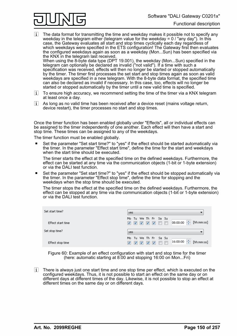
Art. No. 2099REGHE
i The data format for transmitting the time and weekday makes it possible not to specify anyweekday in the telegram either (telegram value for the weekday = 0 / "any day"). In thiscase, the Gateway evaluates all start and stop times cyclically each day regardless ofwhich weekdays were specified in the ETS configuration! The Gateway first then evaluatesthe configured weekdays again as soon as a weekday (Mon...Sun) has been specified viathe KNX in the telegram last received.When using the 8-byte data type (DPT 19.001), the weekday (Mon...Sun) specified in thetelegram can optionally be declared as invalid ("not valid"). If a time with such aspecification was received, effects will then no longer be started or stopped automaticallyby the timer. The timer first processes the set start and stop times again as soon as validweekdays are specified in a new telegram. With the 8-byte data format, the specified timecan also be declared as invalid if necessary. In this case, too, effects will no longer bestarted or stopped automatically by the timer until a new valid time is specified.
i To ensure high accuracy, we recommend setting the time of the timer via a KNX telegramat least once a day.
i As long as no valid time has been received after a device reset (mains voltage return,device restart), the timer processes no start and stop times.
Once the timer function has been enabled globally under "Effects", all or individual effects canbe assigned to the timer independently of one another. Each effect will then have a start andstop time. These times can be assigned to any of the weekdays.The timer function must be enabled globally.o Set the parameter "Set start time?" to "yes" if the effect should be started automatically via
the timer. In the parameter "Effect start time", define the time for the start and weekdayswhen the start time should be executed.The timer starts the effect at the specified time on the defined weekdays. Furthermore, theeffect can be started at any time via the communication objects (1-bit or 1-byte extension)or via the DALI test function.
o Set the parameter "Set start time?" to "yes" if the effect should be stopped automatically viathe timer. In the parameter "Effect stop time", define the time for stopping and theweekdays when the stop time should be executed.The timer stops the effect at the specified time on the defined weekdays. Furthermore, theeffect can be stopped at any time via the communication objects (1-bit or 1-byte extension)or via the DALI test function.
Figure 60: Example of an effect configuration with start and stop time for the timer(here: automatic starting at 8:00 and stopping 16:00 on Mon...Fri)
i There is always just one start time and one stop time per effect, which is executed on theconfigured weekdays. Thus, it is not possible to start an effect on the same day or ondifferent days at different times of the day. Likewise, it is not possible to stop an effect atdifferent times on the same day or on different days.
Page 150 of 257
Software "DALI Gateway C0201x"Functional description
Art. No. 2099REGHE
i If the start and stop time of an effect was configured at the same time of day and the timesare active on the same weekdays, the timer first executes a start and a stop immediatelyafter that. Therefore, it may happen that an effect actually starts and the first effect step isexecuted before the automatic stopping of the effect by the timer occurs. As a result,effects are then not processed completely. For this reason, identical start and stop timesthat are effective on the same weekdays should be avoided.
i The timer always chronologically processes the configured start and stop times of alleffects consecutively to the second (effect 1...16 start time / effect 1...16 stop time). Whensetting the time of day via the KNX, the timer re-evaluates the start and stop times for eacheffect and decides whether the times and thus the starting and stopping of an effect mustbe repeated. The timer only repeats a start or stop time if this is no longer than 60 secondsin the past starting from the newly received time. Attention must be paid to this propertyespecially when setting the timer to a summer/wintertime changeover.Examples:Current time: 1:59:59, configured start time: 2:00:00 -> Even before the internal clock of theGateway switches to 2:00:00, the new time 3:00:00 is already received. -> The timer doesnot execute the start time since it is too far in the past.Current time: 1:59:59, configured start time: 3:00:00 -> The new time 3:00:10 is receivedvia the KNX. -> The timer executes the start time since it is in the timeframe of theretroactive view.
i If a start or stop time has already been processed during a day, this time will not beexecuted a second time on the same day (e.g. by resetting the time). After a change ofday, (i.e. after 00:00:00 / initiated by the time of day itself or by a a change of day in theKNX-time telegram), the timer first evaluates all start and stop times anew if necessary andexecutes start and stop times later in the course of the day according to the configuredtimes and depending on the set weekday.
Disabling functions allow deactivation of the timer if necessary and can thus inhibit an automaticstart or stop command. The configured start and stop times of an effect are not processedduring an active disabling function. It is only possible to start or stop an effect during an activedisabling function by the communication objects or via the DALI test function.Each effect has its own disabling function so that start and stop times of individual effects canbe deactivated individually. Each disabling function has a separate 1-bit disabling object forwhich the telegram polarity can be defined.The disabling functions can be used, for example, if the automatic starting and stopping ofeffects should be suppressed during absence or on holidays.The timer function must be enabled globally.o Set the parameter "Use disabling function for timer?" to "yes". In the parameter "Polarity
disabling object for timer" configure the polarity of the disabling telegram.The 1-bit disabling object is available. The disabling function can be activated anddeactivated via the KNX according to the configured polarity if necessary.
i The disabling functions are always deactivated (object value = "OFF") after a device reset.If the parameter "Polarity disabling object for timer" is configured to "1 = enabled / 0 =disabled", an "OFF" telegram must first be sent to the disabling object after a device resetso that the disabling function is activated.
o Set the parameter "Use disabling function for timer?" to "no".The timer disabling function is not available. Effects can only be started and stopped viathe communication objects or via the DALI test function.
The behaviour of an effect can be defined at the beginning and end of the associated disablingfunction. In this way, a disabling function can stop selectively, or alternatively, just inhibit theexecution of the start and stop times of the timer. When deactivating the disabling functions,effects can be selectively started or stopped. Here too, it is optionally possible to inhibit theautomatic execution of the start and stop times.o Set the parameter "Behaviour at the beginning of the disabling function" to the required
response.
Page 151 of 257
Software "DALI Gateway C0201x"Functional description
Art. No. 2099REGHE
In the "no change" setting, the execution of the start and stop times is inhibited by the timerimmediately at the beginning of the disabling function. This reaction also takes place in the"Stop effect" setting. Additionally, the effect is then also stopped.
o Set the parameter "Behaviour at the end of the disabling function" to the required response.In the "no change" setting, the execution of the start and stop times is enabled again by thetimer at the end of the disabling function. The timer does not repeat any start or stop timesthat were suppressed during an active disabling function. In the "Start effect" setting, theeffect is additionally started. The stopping of the effect at the end of the disabling functioncan be specifically induced by the "Stop effect" setting.
i Starting an effect that has already started or stopping an effect that has already stoppedshows no reaction. An effect must first be stopped, in order to restart it in a defined mannerat Step 1.
Page 152 of 257
Software "DALI Gateway C0201x"Functional description

Art. No. 2099REGHE
4.2.4.6 Emergency lightingThe DALI Gateway can be integrated into DALI emergency lighting systems. It allowsinterference-free operation of operating devices, general lighting systems and emergencylighting operating devices of the same DALI system. The device is able to integrate standardDALI operating devices for lighting control according to IEC 62386-101 (DALI System) and IEC62386-102 (Control Gear) into centrally-supplied emergency lighting systems as an emergencylight.The application principles of a DALI emergency lighting system (emergency light system, scopeof emergency operation, types of emergency lights) are described in more detail in the chapter"Application principles - DALI emergency lighting systems".
i The statutory and standard specifications vary from country to country. In any event,the user / technical planner should check whether the specific specifications shouldbe maintained.
The function "Emergency lighting" is enabled if the parameter "Integration of emergency lights?" in the ETS plug-in of the DALI Gateway in the parameter node "General", is set to "yes" perlimiting value. In this case, the parameter node "Emergency lights", which contains all therelevant parameters for configuring the emergency lighting function, becomes visible.The following chapters describe the configuration of individual functions of emergency lightintegration in the ETS plug-in.
4.2.4.6.1 General configurations
Emergency lights systemNo emergency lights with special DALI operating devices are used in an emergency lightingsystem, supplied by group or central battery systems. Instead, standard devices are usedaccording to the basic DALI standards. These devices, which are primarily intended to controlgeneral DALI lighting systems, usually only possess one mains voltage connection and do notpossess a battery for self-supply, should the mains voltage fail.i This DALI Gateway cannot control any single-battery-operated DALI emergency lights
according to IEC 62386-202.
Emergency lights overall statusThe DALI Gateway is able to evaluate the operating status of all the DALI operating devicesintegrated into the emergency operation in accordance with the transferred error status, and tomake them available collectively to other KNX devices in the form of 1-bit feedback via theobject "Feedback, emergency lights, complete". The status of all the electronic ballastsintegrated into the centrally supplied emergency operation is evaluated. If the Gateway onlydetects a malfunction of only one operating device or of multiple operating devices, it will set theobject value to "1". Otherwise (error-free system), the object value is set to "0". This allows thecentral display of the complete status of a DALI emergency lighting system, e.g. on a KNXvisualisation, meaning that further analyses (e.g. evaluation of the error statuses) can be carriedout. An error is also present when the Gateway can no longer set up communication to anoperating device integrated in emergency operation.The complete status feedback can be used as an active message object or as a passive statusobject. As an active message object, the feedback information is also directly transmitted to thebus whenever there is an update. As a passive status object, there is no telegram transmissionafter an update. In this case, the object value must be read out. The ETS automatically sets theobject communication flags required for proper functioning.
Page 153 of 257
Software "DALI Gateway C0201x"Functional description

Art. No. 2099REGHE
If used as an active message object, the complete status feedback state is transmitted to thebus after bus or mains voltage return or after programming with the ETS, should an error bepresent. In these cases, the feedback telegram can be time-delayed with the delay being presetglobally for all device feedback together. If a time delay is required, the parameter "Time delayfor feedback after bus voltage return" must be set to "yes". Otherwise ("no" setting),transmission of the active message telegram takes place immediately after a device reset and ifthere is an error.Optionally, the complete status feedback, in its function as an active signalling object, can alsobe transmitted cyclically, in addition to transmission on an update. The parameter "Cyclicaltransmission of feedback telegram ?" specifies whether cyclical transmission is enabled or not.If enabled, the parameter "Time for cyclical transmission" on the same parameter page willdefine the cycle time.
Page 154 of 257
Software "DALI Gateway C0201x"Functional description

Art. No. 2099REGHE
4.2.4.6.2 Configurations for centrally-supplied emergency lights
Scope of emergency operation
In centrally-supplied emergency lighting systems, a distinction is made as to which parts of theelectrical building installation are supplied by the emergency power supply. The parameter"Scope of emergency operation" in the parameter node "Emergency lights -> Centrally-supplied" (available if the emergency light system allows for centrally-supplied electronicballasts) defines the scope of the emergency lighting systems...
- "Emergency lights" setting:In this application, either all or just individual DALI operating devices are connected to theemergency power supply. The KNX system and DALI Gateway are not supplied withemergency power, which means that if the mains voltage fails, these subsystems will nolonger function. If there is a fault, there is no DALI voltage because the power supply of theGateway is no longer working.
- "Emergency lights & KNX system" setting:In this application, all or individual DALI operating devices as well as the power supply ofthe KNX system are connected to the emergency power supply. The DALI Gateway is notsupplied with emergency power, which means that it will no longer function if the mainsvoltage fails. If there is a fault, there is no DALI voltage because the power supply of theGateway is no longer working. Since the KNX system continues working withoutinterruption if the mains power fails, mains failure messages that the Gateway can producebefore switch-off (feedback of supply voltage failure) can be evaluated and processed.
- "Emergency lights & KNX system & DALI Gateway" setting:In this application, all or individual DALI operating devices, the power supply of the KNXsystem and the mains voltage connection of the DALI Gateway are connected to theemergency power supply. If there is a fault, DALI voltage will remain since the powersupply of the Gateway continues working. This application offers the greatest flexibility,since the DALI Gateway can continue to control the operating devices. In this application,the DALI operating devices do not switch automatically to the "System Failure Level".Instead, the Gateway controls selected operating devices at a special brightness value foremergency operation. This brightness can be configured in the ETS plug-in within the limitsof minimum and maximum brightness if necessary. Alternatively, it is possible to define nospecial behaviour at the beginning of emergency operation. In this case, the operatingdevices assigned to emergency operation remain at the last set brightness value.
Integration of operating devicesThe Gateway requires the information of which of the DALI operating devices are integrated intocentrally-supplied emergency operation. Furthermore, it is necessary to define the brightnessvalue, optionally also the colour temperature or the behaviour for emergency operation. Eachgroup and device of the single addressing in the project design has special parameters for thispurpose. These parameters are available in the parameter node "Addressing -> Groups... -> [x]Group -> "Emergency lights, centrally-supplied" or "Addressing -> Single devices... -> [x]Electronic ballast -> Emergency lights, centrally-supplied".
Page 155 of 257
Software "DALI Gateway C0201x"Functional description

Art. No. 2099REGHE
Regardless of whether the scope of emergency operation also includes the Gateway (seeparameter "Scope of emergency operation"), the behaviour of all the electronic ballasts of aDALI group or all the single devices in emergency operation can be influenced differently...
- Emergency operation only comprises DALI lights:Due to the switched-off DALI voltage, the operating devices supplied with emergencycurrent set the "System Failure Level" saved in the device at the beginning of emergencyoperation as the brightness value. This brightness value was written by the DALI Gatewayto the DALI operating devices after ETS commissioning. By default, the "System FailureLevel" is defined by the "Behaviour in case of bus voltage failure" parameter of a group orsingle device. Optionally, this value - irrespective of the behaviour in case of bus voltagefailure - can be set to a separate brightness value for emergency operation. For thispurpose, set the parameter "Define separate brightness value for emergency operation ?"to "yes". The parameter "Brightness value in emergency operation" then available definesthe value for the "System Failure Level" regardless of the behaviour in case of bus voltagefailure.When activating operating devices that support the device type "Colour Control" (DALIDevice Type 8), the effective colour temperature in emergency operation does not changein this configuration. The Gateway initialises the DALI operating devices so that the colourtemperature remains unchanged if the DALI voltage fails.
- Emergency operation comprises DALI lights and KNX system:Even in this case, due to the switched-off DALI voltage, the operating devices supplied withemergency current set the "System Failure Level" saved in the device at the beginning ofemergency operation. As in the application "Emergency operation only comprises DALIlights", this brightness value was written by the DALI Gateway to the DALI operatingdevices after ETS commissioning. Optionally, this value - irrespective of the behaviour incase of bus voltage failure - can be set to a separate brightness value for emergencyoperation. For this purpose, set the parameter "Define separate brightness value foremergency operation ?" to "yes". The parameter "Brightness value in emergencyoperation" then available defines the value for the "System Failure Level" regardless of thebehaviour in case of bus voltage failure.When activating operating devices that support the device type "Colour Control" (DALIDevice Type 8), the effective colour temperature in emergency operation does not changeeven in this configuration. The Gateway initialises the DALI operating devices so that thecolour temperature remains unchanged if the DALI voltage fails.
- Emergency operation comprises DALI lights, KNX system and DALI Gateway(recommended application):In this application, the DALI operating devices do not switch automatically to the "SystemFailure Level". Instead, the Gateway controls selected operating devices to the brightnessvalue specified by the parameter "Brightness at the start of emergency operation". Thisparameter is available if the parameter "Define behaviour at the start of emergencyoperation ?" is configured to "yes". Otherwise ("no" setting), the operating devices assignedto emergency operation remain at the last set brightness values.The brightness value specified by the parameter "Brightness at the start of emergencyoperation" is also entered into the DALI operating devices as the System Failure Level. Ifthe mains voltage supply of the DALI Gateway should fail, and consequently the DALIvoltage, the operating devices affected will also set themselves to this brightness value. Ifthe parameter is unavailable (parameter "Define behaviour at the start of emergencyoperation ?" set to "no"), the "System Failure Level" is defined by the "Behaviour in case ofbus voltage failure" parameter of a group or single device.When activating operating devices that support the device type "Colour Control" (DALIDevice Type 8), a colour temperature can also be defined for the emergency operationbesides a brightness value in this configuration. The parameter "Colour temperature at thebeginning of emergency operation" specifies this colour temperature value and is availableas long as the parameter "Define behaviour at the start of emergency operation ?" isconfigured to "yes". Otherwise ("no" setting), the operating devices assigned to emergencyoperation remain at the last set colour temperature value.
Page 156 of 257
Software "DALI Gateway C0201x"Functional description

Art. No. 2099REGHE
i DALI groups or single devices integrated in centrally supplied emergency lighting operationcannot be assigned to any scene and effect! Assignments to scenes and effects are lost ifthe integration of groups or devices takes place later in emergency operation. In thesecases, the ETS plug-in warns of losing assignments.
Monitoring power supply failure If the scope of emergency operation also allows for the integration of the DALI Gateway, theGateway will activate emergency operation. It instigates all the appropriate actions on the KNXand the DALI page. Identification of a mains failure as the cause of emergency operation cantake place in different ways. Either the Gateway automatically identifies whether mains voltageis present (internal failure messages) or not using the diagnosis of the DALI operating devices.This is possible through contacting and reading out all commissioned DALI devices. If a numberof these devices specified by the programmer do not respond, the Gateway will assume that themains voltage has failed.In addition, or alternatively, a KNX telegram can inform the Gateway that emergency operationis to be activated (external failure message). This is useful, for example, when a KNX binaryinput is monitoring the mains voltage and transmits a message telegram if there is a mainsfailure.The parameter "Monitoring for the failure of the general power supply ?" in the parameter node"Emergency lights -> Centrally-supplied -> Emergency lights & KNX system & DALI Gateway"defines whether the detection of a mains voltage failure will take place using an internal DALIfailure message or, alternatively, using an external KNX failure message. Both options can becombined and linked logically (AND, OR), which means that a higher guarantee of detection orredundancy can be implemented during failure detection.
- Internal DALI failure message:With the internal DALI failure message, all the planned and commissioned DALI operatingdevices are polled cyclically (same interval in seconds as for determining the error status).Should one of the devices no longer respond to the Gateway, the operating deviceconcerned will be saved internally as "failed". As a result, the DALI Gateway will assumethat the mains voltage supply of the DALI operating device has failed. In the ETS plug-in,the parameter "Maximum number of failed devices" (1...64) can be used to define howmany devices must be identified as "failed" for the Gateway to activate emergencyoperation. If the number of failed devices reaches or exceeds the configured limit value,then failure of the general mains power supply is assumed. If the limit value was notreached, the Gateway will remain in normal operation.
i The standard setting of the parameter "Maximum number of failed devices" is "64", whichmeans that all the DALI operating devices must fail before emergency operation isactivated. This number is not usually reached in practical applications since emergencylighting systems always have some electronic ballasts integrated into the centralemergency power supply. Consequently, these operating devices do not fail in the event ofa mains voltage failure and can therefore not be identified by the Gateway as "failed",which means that the maximum limit value of 64 operating devices can never be reached.If the internal DALI failure message is being used, the parameter "Maximum number offailed devices" must always then be set to the required number of devices and thusadjusted to the number of DALI subscribers in the DALI system which are not supplied withemergency current.
- External KNX failure message:In the case of the external KNX failure message, a different KNX bus device (e.g. binaryinput) can inform the DALI Gateway via the 1-bit object ("Failure, external supply") that thegeneral mains voltage supply has failed. With this, the Gateway then activates emergencyoperation. The telegram polarity of the object is fixed: "1" = Mains voltage has failed, "0" =Mains voltage available.
Page 157 of 257
Software "DALI Gateway C0201x"Functional description
Art. No. 2099REGHE
i Updates to the object "Failure, external supply" from "1" to "1" or "0" to "0" do not produceany reaction.
If the internal and external failure messages are interlinked, the Gateway will then use the setlogical link to test whether emergency operation is to be activated or not. In the setting "Failuremessage DALI OR KNX (internal OR external"), the Gateway must either have independentlyidentified that the defined number of DALI devices has failed, or must have been informedexternally about the mains failure. Only one positive failure message is decisive in activatingemergency operation.In the setting "Failure message DALI AND KNX (internal AND external)", both the internal andexternal evaluation must be positive in order for the emergency operation to be activated If onlyone failure message is active, emergency operation will not be activated. In addition, activeemergency operation will be terminated as soon as a failure message becomes inactive again.i After a device reset (mains voltage failure and return on the Gateway, ETS programming
operation), emergency operation is always deactivated.
Message: Failure, general supplyA 1-bit failure telegram can be transmitted to the KNX as feedback either through the internalfailure message, or alternatively, through the external failure message, provided that theGateway has activated emergency operation. This allows other bus devices evaluating thisfeedback (e.g. other KNX DALI Gateways) to react and also activate emergency operation.Automatic identification of a mains voltage failure is usually not necessary with these devices,which means that only one DALI Gateway in the KNX system needs to be integrated activelyinto mains failure detection.If necessary, the object "Feedback, supply failure" is enabled by the parameter "Message,general supply failure ?" in the parameter node "Emergency lights -> Centrally-supplied ->Emergency lights & KNX system & DALI Gateway". This object causes telegram transmissionas soon as the Gateway activates ("1 telegram / mains voltage failed) or deactivates ("0"telegram / mains voltage available again) emergency operation.i After a device reset (mains voltage failure and return on the Gateway, ETS programming
operation), emergency operation is always deactivated. No telegram transmission takesplace via the object "Feedback, supply failure", not even if emergency operation was activebefore the reset.
i "Feedback, supply failure" is transmitted immediately as soon as the Gateway detects thefailure or return of the mains voltage. It should be noted that the deactivation of emergencyoperation after the return of mains voltage can take place after a delay.Feedback is not generated if emergency operation was activated or deactivated using theobject "Emergency operation, external message".
Reaction to external messageThe DALI Gateway does not need to monitor its own DALI system or external failure messagesitself in order to identify the failure of the general mains voltage supply and thus to activateemergency operation. Optionally, it can be switched to emergency operation by an externalmessage. When using the external message, only one DALI Gateway (Master) in the KNXsystem needs to be integrated actively into mains failure detection. All other Gateways - ifavailable - will then evaluate the external feedback of this Master. Alternatively, a Gateway canbe controlled using the external message from any KNX device.If necessary, the object "Emergency operation, external message" is enabled by the parameter"Allow reaction to external message ?" in the parameter node "Emergency lights -> Centrally-supplied -> Emergency lights & KNX system & DALI Gateway". Using this 1-bit object, adifferent KNX bus device (e.g. another DALI Gateway -> link to the object "Feedback, supplyfailure") can inform the DALI Gateway that emergency operation has been activated. Throughthis, the Gateway then activates emergency operation, without having to identify the failure of
Page 158 of 257
Software "DALI Gateway C0201x"Functional description
Art. No. 2099REGHE
the general mains voltage supply itself. The telegram polarity is fixed: "1" = Mains voltage hasfailed / Activate emergency operation, "0" = Mains voltage available / Deactivate emergencyoperation.i In special cases, it is possible to combine the monitoring for failures in the mains voltage
supply (through an internal and/or external failure message) with the reaction to an externalmessage. This is useful, for example, when the Gateway is to monitor the existence ofmains voltage independently and, in addition, it must be possible to execute the forcedactivation and deactivation of emergency operation - for example for servicing purposes.Emergency operation can be controlled independently using the object "Emergencyoperation, external message" to monitor for failures in the general mains voltage supply.
Behaviour at the end of emergency operationIf the Gateway deactivates emergency operation (due to internal or external failure monitoring ofthe mains voltage or an external message telegram), all the DALI groups or single devicesintegrated in centrally supplied emergency operation are switched to defined brightness colourtemperature states (colour temperature only when using the tunable white function). Thebehaviour at the end of emergency operation is specified globally by the parameter of the samename in the parameter node "Emergency lights -> Centrally supplied -> Emergency lights &KNX system & DALI Gateway" separated for brightness and colour temperature. This meansthat the switching off or the activation of a defined brightness value can be configured.Alternatively, the brightness value active before emergency operation or the brightness valuetracked internally during emergency operation can be set. As a final alternative, it is possible toretain the current state of all operating devices.The colour temperature can be influenced at the end of emergency operation so that either acolour temperature value is specified or the internally tracked colour temperature is set duringemergency operation. As a further option, the effective colour temperature during activeemergency operation can remain unchanged at the end of emergency operation.i In the settings "Brightness value" or "Colour temperature value", values can be configured
in the full value range without restriction. The minimum and maximum values of theindividual DALI groups or single devices are not taken into account here when setting theparameter. If brightness values or colour temperature values that undershoot the individualminimum values or exceed the maximum values are defined for the behaviour at the end ofemergency operation, then the groups or single devices concerned are limited to thecorresponding limit values.
Deactivation of emergency operation and thus the execution of the behaviour at the end ofemergency operation can take place after a delay. A time delay is advisable in order to giveDALI operating devices without an emergency current supply sufficient time after the return ofmains voltage to switch on at the operating brightness and colour temperature. The delay timemeans that DALI emergency lights are only switched off or switched to normal operation whenthe standard lighting is ready for operation.The parameter "Delay time at the end of emergency operation" defines the period of time fromthe identification of the return of mains voltage until the actual deactivation of emergencyoperation. In the "00:00" setting, emergency operation is deactivated without a delay.i If the mains voltage fails again during a delay or an external message telegram forces the
Gateway into emergency operation, emergency operation will remain activated withoutinterruption.
Feedback emergency operationThe DALI Gateway is able to make the state of emergency operation available on the KNX inthe form of 1-bit feedback via the object "Feedback, emergency operation status". This allowsother KNX bus devices to be informed about emergency operation in order to control displaysfor users (e.g. in a visualisation) or to carry out further actions (e.g. remote forwarding via thetelephone or IP data network through suitable KNX components). If emergency operation is
Page 159 of 257
Software "DALI Gateway C0201x"Functional description

Art. No. 2099REGHE
activated, the Gateway sets the object value to "1". Otherwise (emergency operationdeactivated), the object value is set to "0".If the feedback function is to be used, it must be enabled in the parameter node "Emergencylights -> Centrally-supplied -> Emergency lights & KNX system & DALI Gateway -> Feedback,emergency operation" using the parameter "Feedback 'Emergency operation status' ?".The emergency operation feedback can be used as an active message object or as a passivestatus object. As an active message object, the feedback information is also directly transmittedto the bus whenever there is an update. As a passive status object, there is no telegramtransmission after an update. In this case, the object value must be read out. The ETSautomatically sets the object communication flags required for proper functioning.If used as an active message object, the feedback state is transmitted to the bus after bus ormains voltage return or after programming with the ETS, provided that emergency operation isactivated. In these cases, the feedback telegram can be time-delayed with the delay beingpreset globally for all device feedback together (see page 68). If a time delay is required, theparameter "Time delay for feedback after bus voltage return ?" must be set to "yes". Otherwise("no" setting), transmission of the active message telegram takes place immediately after adevice reset and if there is active emergency operation.Optionally, the emergency operation feedback in its function as an active signalling object canalso be transmitted cyclically, in addition to transmission on an update. The parameter "Cyclicaltransmission of feedback telegram ?" specifies whether cyclical transmission is enabled or not.If enabled, the parameter "Time for cyclical transmission" on the same parameter page willdefine the cycle time.i After a device reset (mains voltage failure and return on the Gateway, ETS programming
operation), emergency operation is always deactivated. No telegram transmission takesplace via the active object "Feedback, emergency operation status", not even if emergencyoperation was active before the reset.
Page 160 of 257
Software "DALI Gateway C0201x"Functional description

Art. No. 2099REGHE
4.2.4.7 DALI commissioning
4.2.4.7.1 Starting DALI commissioningIt is easy to configure the devices of the DALI Gateway, including the configuration of the DALIgroups, the single devices, the scenes and effects using the plug-in embedded in the ETS. Inaddition, DALI commissioning via the KNX bus cable can also be performed using the plug-in.No additional tool and no special programming connection is required.DALI commissioning must be performed after device configuration has been completed (allgroups and single devices created / scenes, effects and emergency lights configured / all groupaddresses assigned). In addition, it is necessary that the DALI Gateway has been programmedwith the ETS at least once before DALI commissioning so that the device has a physicaladdress and the application program is loaded .i DALI commissioning is not necessary, and thus not available in the ETS plug-in if the
addressing allows for a master control.
If the necessary requirements have been fulfilled, "DALI commissioning" can be executed onthe parameter page of the same name in the plug-in. After selecting the commissioning pageand successful communication with the DALI Gateway, the commissioning environmentbecomes visible in the right-hand pane of the plug-in (figure 61).
Figure 61: DALI commissioning environment in the ETS plug-in
When the commissioning environment is recalled, the plug-in first tries to communicate with theDALI Gateway via the KNX bus connection of the ETS (figure 62) and checks whether DALIcommissioning is possible. For this reason, the DALI Gateway must be connected to the KNXbus cable and the bus and mains voltage supply must be switched on when DALIcommissioning is recalled. In addition, the ETS must have a functioning communicationsinterface to the bus (e.g. USB or KNXnet/IP).i In this situation, the Gateway does not check the function of the DALI cable.If it is not be possible to setup a connection to the DALI Gateway in this situation, the plug-in willterminate commissioning. The commissioning environment will become visible even though thecommissioning functions are not available. The following section lists the causes for a faultyconnection and the appropriate remedies...
Page 161 of 257
Software "DALI Gateway C0201x"Functional description
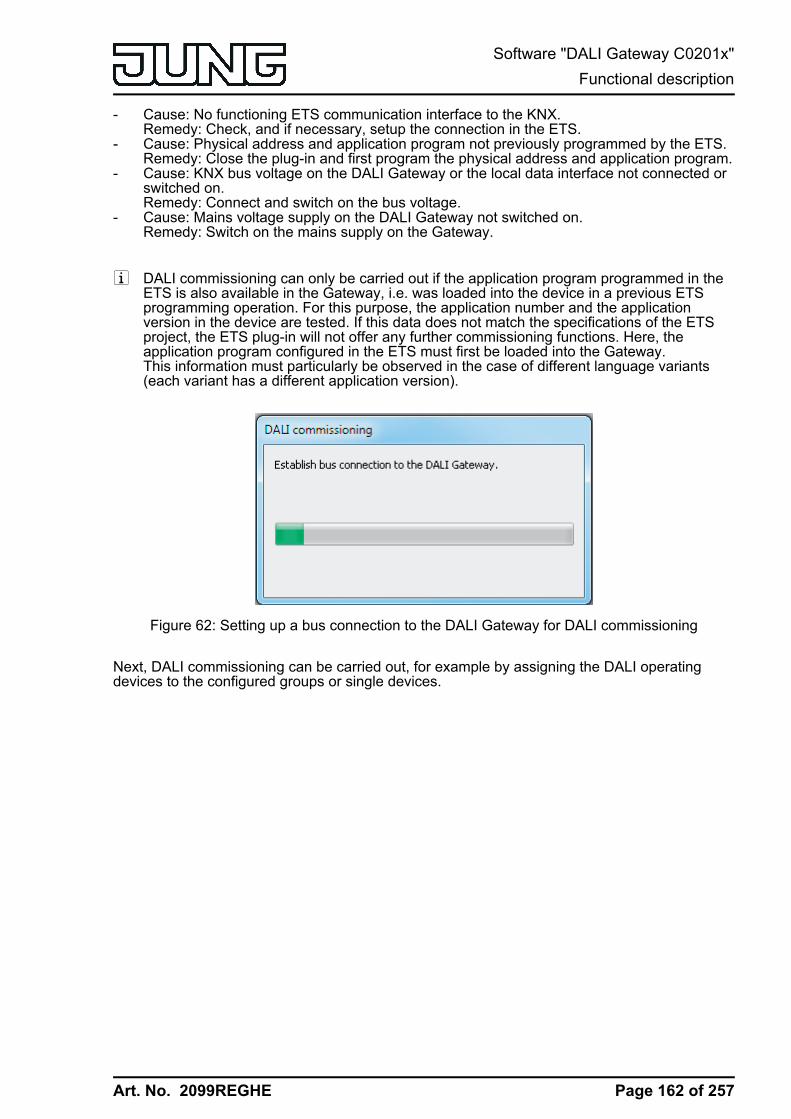
Art. No. 2099REGHE
- Cause: No functioning ETS communication interface to the KNX.Remedy: Check, and if necessary, setup the connection in the ETS.
- Cause: Physical address and application program not previously programmed by the ETS.Remedy: Close the plug-in and first program the physical address and application program.
- Cause: KNX bus voltage on the DALI Gateway or the local data interface not connected orswitched on.Remedy: Connect and switch on the bus voltage.
- Cause: Mains voltage supply on the DALI Gateway not switched on.Remedy: Switch on the mains supply on the Gateway.
i DALI commissioning can only be carried out if the application program programmed in theETS is also available in the Gateway, i.e. was loaded into the device in a previous ETSprogramming operation. For this purpose, the application number and the applicationversion in the device are tested. If this data does not match the specifications of the ETSproject, the ETS plug-in will not offer any further commissioning functions. Here, theapplication program configured in the ETS must first be loaded into the Gateway.This information must particularly be observed in the case of different language variants(each variant has a different application version).
Figure 62: Setting up a bus connection to the DALI Gateway for DALI commissioning
Next, DALI commissioning can be carried out, for example by assigning the DALI operatingdevices to the configured groups or single devices.
Page 162 of 257
Software "DALI Gateway C0201x"Functional description

Art. No. 2099REGHE
4.2.4.7.2 Performing DALI commissioningDuring DALI commissioning, the max. 64 DALI operating devices of a DALI system areassigned to the programmed groups or single devices of the Gateway. Only this assignmentcreates the option of controlling the DALI operating devices individually or jointly via the KNX.The "addressing type" defined in the ETS plug-in specifies whether group and/or single devicecontrol is possible.Any number of DALI operating devices can be assigned to groups 1...16. On the DALI side,addressing takes place using group addresses, which the Gateway configures invisibly for theuser and manages on its own. During DALI commissioning, the operating devices concernedare automatically programmed accordingly. In contrast, only up to two DALI operating devicescan be assigned to groups 17...32. Since there are no DALI group addresses for these groups,DALI addressing takes place using the device short addresses, which means that the operatingdevices are addressed, and thus contacted, individually.Alternatively, DALI operating devices can be addressed as single devices. The addressing ofthese devices takes place individually using the device short addresses.i DALI operating devices can either be integrated only in single device addressing, or
alternatively, in group addressing. It is not possible to control an operating device with bothaddressing types. Operating devices integrated in group control can no longer beaddressed as a single device. The reverse case applies in the same manner.
The commissioning environment of the plug-in is divided up into two panes. The right-handpane lists the operating devices found in the DALI system. The left-hand pane displays thecreated groups. The assignment of the DALI devices to the programmed groups or singledevices also takes place there.(figure 63).
The pane of the programmed DALI devices (A) displays all the groups and single devicesconfigured in the ETS plug-in. In the later course of DALI commissioning, this area plays host tothe assignment to found electronic ballasts of the DALI system. Groups can contain multipleelectronic ballasts, whereby single devices can only ever contain one electronic ballast. Selectwhether the panel displays groups or single devices, thus allowing assignments to theseelements, by pressing the Single devices or Groups buttons in the top area of the pane.Single devices added to groups during DALI commissioning or as part of offline commissioningare also available in the "Single devices" view. This creates the option of detecting all theprogrammed single devices centrally in just one commissioning window.Different columns of the window of the programmed devices show the programmed shortaddresses of the devices (1...64), the device names, optionally the DALI device types (if the useof device types is configured or required) and the assignment status of found electronic ballasts("not assigned", "assigned"). The devices can be assigned individually, either in the projectdesign of the single devices (under "Addressing -> Groups... -> [x] Group -> Single devices ->[x] Electronic ballast" or "Addressing -> Single devices... -> [x] Electronic ballast") oralternatively, using the Rename button in the control panel of the commissioning dialog (E).This allows clear labelling of the operating devices (e.g. "Lamp, entrance area" or "Light strip,window, south").
Page 163 of 257
Software "DALI Gateway C0201x"Functional description
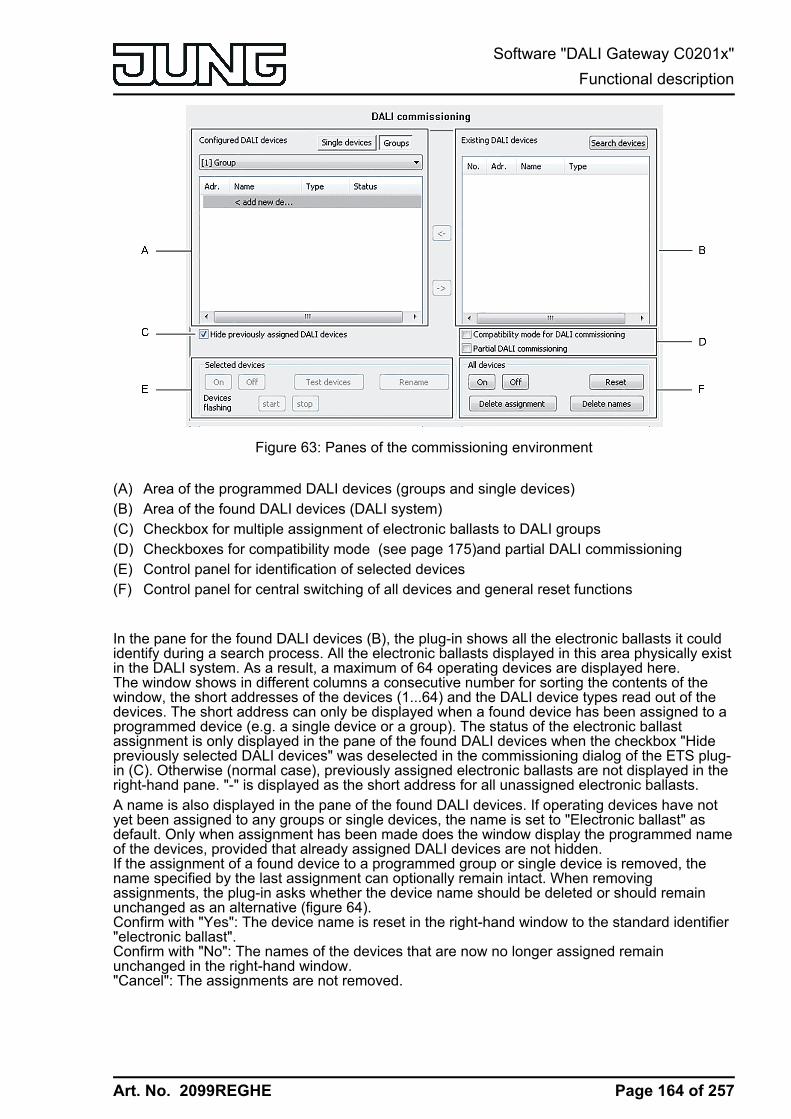
Art. No. 2099REGHE
Figure 63: Panes of the commissioning environment
(A) Area of the programmed DALI devices (groups and single devices)(B) Area of the found DALI devices (DALI system)(C) Checkbox for multiple assignment of electronic ballasts to DALI groups(D) Checkboxes for compatibility mode (see page 175)and partial DALI commissioning(E) Control panel for identification of selected devices(F) Control panel for central switching of all devices and general reset functions
In the pane for the found DALI devices (B), the plug-in shows all the electronic ballasts it couldidentify during a search process. All the electronic ballasts displayed in this area physically existin the DALI system. As a result, a maximum of 64 operating devices are displayed here.The window shows in different columns a consecutive number for sorting the contents of thewindow, the short addresses of the devices (1...64) and the DALI device types read out of thedevices. The short address can only be displayed when a found device has been assigned to aprogrammed device (e.g. a single device or a group). The status of the electronic ballastassignment is only displayed in the pane of the found DALI devices when the checkbox "Hidepreviously selected DALI devices" was deselected in the commissioning dialog of the ETS plug-in (C). Otherwise (normal case), previously assigned electronic ballasts are not displayed in theright-hand pane. "-" is displayed as the short address for all unassigned electronic ballasts.A name is also displayed in the pane of the found DALI devices. If operating devices have notyet been assigned to any groups or single devices, the name is set to "Electronic ballast" asdefault. Only when assignment has been made does the window display the programmed nameof the devices, provided that already assigned DALI devices are not hidden.If the assignment of a found device to a programmed group or single device is removed, thename specified by the last assignment can optionally remain intact. When removingassignments, the plug-in asks whether the device name should be deleted or should remainunchanged as an alternative (figure 64).Confirm with "Yes": The device name is reset in the right-hand window to the standard identifier"electronic ballast".Confirm with "No": The names of the devices that are now no longer assigned remainunchanged in the right-hand window."Cancel": The assignments are not removed.
Page 164 of 257
Software "DALI Gateway C0201x"Functional description
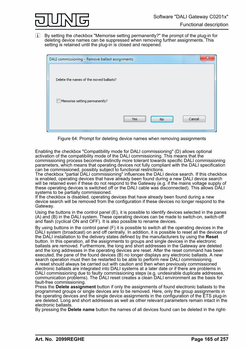
Art. No. 2099REGHE
i By setting the checkbox "Memorise setting permanently?" the prompt of the plug-in fordeleting device names can be suppressed when removing further assignments. Thissetting is retained until the plug-in is closed and reopened.
Figure 64: Prompt for deleting device names when removing assignments
Enabling the checkbox "Compatibility mode for DALI commissioning" (D) allows optionalactivation of the compatibility mode of the DALI commissioning. This means that thecommissioning process becomes distinctly more tolerant towards specific DALI commissioningparameters, which means that operating devices not fully compliant with the DALI specificationcan be commissioned, possibly subject to functional restrictions.The checkbox "partial DALI commissioning" influences the DALI device search. If this checkboxis enabled, operating devices that have already been found during a new DALI device searchwill be retained even if these do not respond to the Gateway (e.g. if the mains voltage supply ofthese operating devices is switched off or the DALI cable was disconnected). This allows DALIsystems to be partially commissioned.If the checkbox is disabled, operating devices that have already been found during a newdevice search will be removed from the configuration if these devices no longer respond to theGateway.Using the buttons in the control panel (E), it is possible to identify devices selected in the panes(A) and (B) in the DALI system. These operating devices can be made to switch-on, switch-offand flash (cyclical ON and OFF). It is also possible to rename devices.By using buttons in the control panel (F) it is possible to switch all the operating devices in theDALI system (broadcast) on and off centrally. In addition, it is possible to reset all the devices ofthe DALI installation to the delivery states defined by the manufacturers by using the Resetbutton. In this operation, all the assignments to groups and single devices in the electronicballasts are removed. Furthermore, the long and short addresses in the Gateway are deletedand the long addresses in the operating devices are reset. After the reset command has beenexecuted, the pane of the found devices (B) no longer displays any electronic ballasts. A newsearch operation must then be restarted to be able to perform new DALI commissioning.A reset should always be carried out with caution and then when previously commissionedelectronic ballasts are integrated into DALI systems at a later date or if there are problems inDALI commissioning due to faulty commissioning steps (e.g. undesirable duplicate addresses,communication problems). The DALI reset creates a clean DALI environment as the basis forfault-free commissioning.Press the Delete assignment button if only the assignments of found electronic ballasts to theprogrammed groups or single devices are to be removed. Here, only the group assignments inthe operating devices and the single device assignments in the configuration of the ETS plug-inare deleted. Long and short addresses as well as other relevant parameters remain intact in theelectronic ballasts.By pressing the Delete name button the names of all devices found can be deleted in the right-
Page 165 of 257
Software "DALI Gateway C0201x"Functional description
Art. No. 2099REGHE
hand window. If all or some of the devices found are connected to programmed devices (left-hand window), then the name of the programmed devices concerned will be reset.i It is not possible to reset individual or specific electronic ballasts.i After a reset of the DALI system or after deletion of assignments, it is always necessary to
reload the application program into the DALI Gateway after commissioning using the ETS.
Searching for DALI operating devicesDuring initial commissioning, the connected DALI operating devices must be searched for andidentified. If the DALI Gateway has already been commissioned at least once, then the searchfor operating devices is only required if new devices were added to the DALI system or if theETS product database was changed and hence the device is completely reconfigured. At theend of DALI commissioning, the commissioning parameters (identified operating devices withlong and short address, names of the operating devices, group/device assignment and devicetype) are written to the ETS database and are thus saved. The saved data is displayed whenthe commissioning environment is started.During initial commissioning, no DALI operating devices are displayed in the right-hand windowarea (B). To continue commissioning, the operating devices connected to the DALI cable mustfirst be searched for. The devices affected must be connected to the DALI cable withoutinterruption and operational in order for the DALI Gateway to be able to find and identify allnecessary DALI operating devices during the device search! In addition, the mains voltagesupply of the DALI Gateway must be switched on.o Click the "Search for devices" button in the commissioning environment.
The DALI Gateway searches for available DALI operating devices. In so doing, theGateway scans the DALI cable in stages and identifies the connected devicessuccessively. Depending on the number of connected electronic ballasts, the searchoperation may take some time. During the search operation, the plug-in displays theprogress of the search.(figure 65).
i During the search operation, the Gateway tells the DALI operating devices to create arandom long address internally. This only takes place for devices which were identified as"newly found" at the beginning of the search operation. In addition, the Gateway alreadyassigns short addresses in the background during the search process, which are thenadapted using group and device assignments in the course of commissioning and can thusbe overwritten.The plug-in uses the long addresses to distinguish between the found operating devicesbeing detected for the first time and those devices which were previously detected duringcommissioning. For this, the plug-in compares the read-in long addresses with the entriessaved in the ETS database. Previously unknown long addresses indicate newly founddevices.Taking this distinction into account, the plug-in displays the newly found electronic ballastsin the search progress. In the case of first DALI commissioning, all the found operatingdevices are indicated as "newly found". In later commissioning operations, only thoseelectronic ballasts are indicated as newly found, which were added to the DALI system.
i According to the DALI specification, all the DALI subscribers must save the long addresspermanently (e.g. even during mains voltage failures). Not all the DALI devices on themarket support this requirement. If such operating devices are installed, compatibility modeshould be activated. (see page 175). During a search operation, the Gateway thenidentifies solely by means of the DALI short address (1...64) contained in the devices. Thismeans that electronic ballasts can be commissioned without accessing long addresses.After completion of the search operation, all the identified operating devices (both old andnew) are listed in the right-hand pane of the commissioning environment.(figure 66).
Page 166 of 257
Software "DALI Gateway C0201x"Functional description

Art. No. 2099REGHE
Figure 65: Example of search progress during a DALI operating device search
Figure 66: Example of a device list after a search operation
i An error on the DALI cable is not detected by the DALI Gateway during a device search. Inthe case of a short-circuit, for example, the Gateway attempts cyclically to set up DALIcommunication. As this is not possible, the plug-in remains permanently in the devicesearch. DALI operating devices are not detected if there is a cable break, for example.
i During the device search, all the connected DALI operating devices switch to minimumbrightness. This makes it possible to determine whether the devices are actuallyfunctioning and react to the device search.
Partial DALI commissioning:The checkbox "partial DALI commissioning" influences the DALI device search. A distinction ismade between the two following cases depending on whether the checkbox is enabled ordisabled:
Page 167 of 257
Software "DALI Gateway C0201x"Functional description

Art. No. 2099REGHE
1. Checkbox enabled: Operating devices that have already been found during a new DALIdevice search will be retained even if these do not respond to the Gateway (e.g. if the mainsvoltage supply of these operating devices is switched off or the DALI cable was disconnected).This allows DALI systems to be partially commissioned (e.g. commissioning of multipleconstruction phases). With this setting, make sure that no more than 64 operating devices areconnected in the overall extension of the DALI system!
2. Checkbox disabled: In this case, operating devices that have previously been found during anew device search will be removed from the configuration if these devices no longer respond tothe Gateway. With this setting, ensure that the entire DALI system is switched on and ready foroperation. Thus, it is not permissible to switch off previously commissioned electronic ballasts orto disconnect them from the DALI cable. During the entire commissioning process, fault-freecommunication must be guaranteed between the DALI Gateway and all DALI operating devices.
i Operating devices that have been found cannot be removed from the configuration whenusing the partial commissioning (checkbox enabled). It is only possible to remove operatingdevices that have already been found by permanently or temporarily switching to thestandard commissioning (checkbox disabled) and by executing a new device search forwhich the previously found devices no longer respond. It should then be ensured that allother operating devices of the DALI system are connected to the DALI cable and areoperational! Otherwise, devices will also be removed from the configuration, which shouldbe retained.
i When using the partial commissioning (checkbox enabled) in conjunction with thecompatibility mode, make sure that operating devices that should be partially searched forby a device search and newly added have not already been programmed with an invalidshort address. This is the case, for example, if operating devices were already previouslycommissioned in another DALI system. Ideally, brand new operating devices partially inconjunction with the compatibility mode should only be commissioned. If this is notpossible, it makes sense to carry out a DALI reset (resetting operating devices concernedto the delivery state). When doing so, make sure that the reset is only carried out if just theoperating devices that should be newly added are connected to the DALI system.Otherwise, the operating devices that were already validly commissioned will be reset.
Assigning groupsAfter operating devices have been searched for and identified, the devices can be assigned tothe programmed groups or single devices. The following sections document the individualactions to be taken to create a group assignment in the DALI commissioning environment.i The assignment of DALI operating devices to groups is only then possible when the
addressing type allows for group control.Assignment always takes place by moving the devices listed in the right-hand section into theleft-hand section. Assignment is carried out by pressing the <- button between the two sections,or alternatively, by "drag and drop" with the mouse. An assignment can be removed again byselecting an assigned operating device and, using the -> button or the mouse, shifting it back tothe list box of available DALI devices. It is possible to assign multiple operating devicessimultaneously, or to remove them from an assignment.Each assigned electronic ballast requires a device in the Gateway project design, so that thedevice name, the short address and, optionally, the DALI device type can be configured. As aresult, there is also a programmable single device for each group assignment of an electronicballast. There are two options for assigning found electronic ballasts to a group...
1. Group assignment by creating a new single device in the groupPressing the <- button automatically creates a new single device in the group. Here, no existing,and as yet unassigned single device of the group may be highlighted. Alternatively, assignmentusing "Drag and Drop" with the mouse is possible by dragging a found electronic ballast in theright-hand pane and dropping it into the left window in the area "<Add new device>" (first listentry). The plug-in automatically assigns the first free short address to the new device. The
Page 168 of 257
Software "DALI Gateway C0201x"Functional description
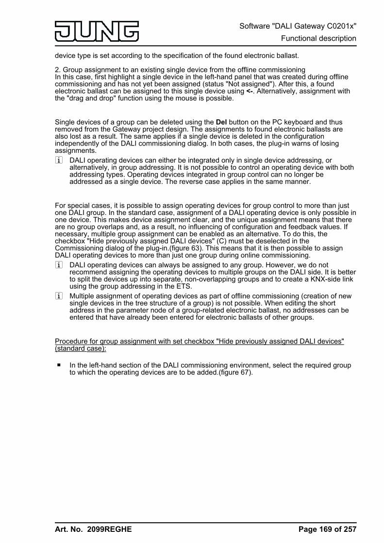
Art. No. 2099REGHE
device type is set according to the specification of the found electronic ballast.
2. Group assignment to an existing single device from the offline commissioningIn this case, first highlight a single device in the left-hand panel that was created during offlinecommissioning and has not yet been assigned (status "Not assigned"). After this, a foundelectronic ballast can be assigned to this single device using <-. Alternatively, assignment withthe "drag and drop" function using the mouse is possible.
Single devices of a group can be deleted using the Del button on the PC keyboard and thusremoved from the Gateway project design. The assignments to found electronic ballasts arealso lost as a result. The same applies if a single device is deleted in the configurationindependently of the DALI commissioning dialog. In both cases, the plug-in warns of losingassignments.i DALI operating devices can either be integrated only in single device addressing, or
alternatively, in group addressing. It is not possible to control an operating device with bothaddressing types. Operating devices integrated in group control can no longer beaddressed as a single device. The reverse case applies in the same manner.
For special cases, it is possible to assign operating devices for group control to more than justone DALI group. In the standard case, assignment of a DALI operating device is only possible inone device. This makes device assignment clear, and the unique assignment means that thereare no group overlaps and, as a result, no influencing of configuration and feedback values. Ifnecessary, multiple group assignment can be enabled as an alternative. To do this, thecheckbox "Hide previously assigned DALI devices" (C) must be deselected in theCommissioning dialog of the plug-in.(figure 63). This means that it is then possible to assignDALI operating devices to more than just one group during online commissioning.i DALI operating devices can always be assigned to any group. However, we do not
recommend assigning the operating devices to multiple groups on the DALI side. It is betterto split the devices up into separate, non-overlapping groups and to create a KNX-side linkusing the group addressing in the ETS.
i Multiple assignment of operating devices as part of offline commissioning (creation of newsingle devices in the tree structure of a group) is not possible. When editing the shortaddress in the parameter node of a group-related electronic ballast, no addresses can beentered that have already been entered for electronic ballasts of other groups.
Procedure for group assignment with set checkbox "Hide previously assigned DALI devices"(standard case):
o In the left-hand section of the DALI commissioning environment, select the required groupto which the operating devices are to be added.(figure 67).
Page 169 of 257
Software "DALI Gateway C0201x"Functional description
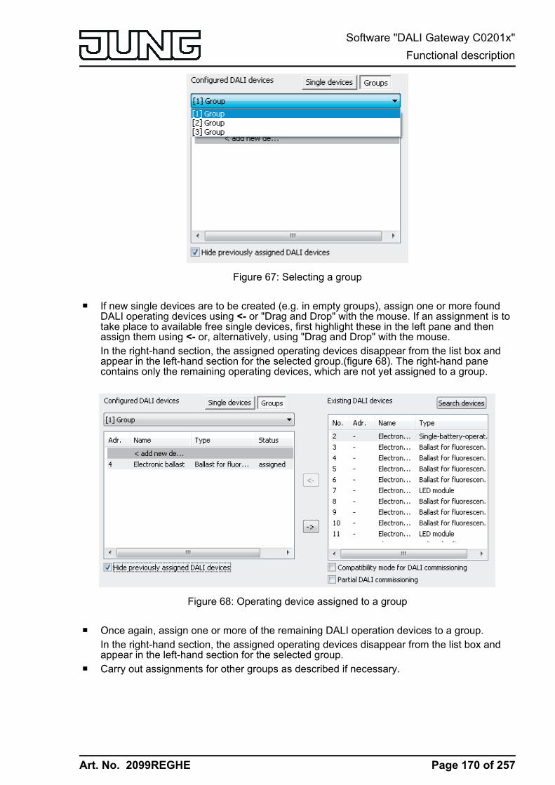
Art. No. 2099REGHE
Figure 67: Selecting a group
o If new single devices are to be created (e.g. in empty groups), assign one or more foundDALI operating devices using <- or "Drag and Drop" with the mouse. If an assignment is totake place to available free single devices, first highlight these in the left pane and thenassign them using <- or, alternatively, using "Drag and Drop" with the mouse.In the right-hand section, the assigned operating devices disappear from the list box andappear in the left-hand section for the selected group.(figure 68). The right-hand panecontains only the remaining operating devices, which are not yet assigned to a group.
Figure 68: Operating device assigned to a group
o Once again, assign one or more of the remaining DALI operation devices to a group.In the right-hand section, the assigned operating devices disappear from the list box andappear in the left-hand section for the selected group.
o Carry out assignments for other groups as described if necessary.
Page 170 of 257
Software "DALI Gateway C0201x"Functional description

Art. No. 2099REGHE
Procedure for group assignment with deactivated checkbox "Hide previously assigned DALIdevices" (special case):
o In the left-hand section of the DALI commissioning environment, select the required groupto which the operating devices are to be added.
o Assign one or more available DALI operation devices to the group, as described above.The assigned operating devices remain visible in the right-hand section and also appear inthe left-hand section for the selected group.(figure 69). In the right-hand area, theseelectronic ballasts receive the short address of the assignment.
Figure 69: Operating device assigned to a groupHere: Electronic ballast with the address 3 is assigned to multiple groups.
o If necessary, select a further group in the left-hand section.o Once again, assign one or more available DALI operation devices to a group.
If a previously-assigned operation device is to be assigned to an additional group, the plug-in signals that the device has already been assigned to a different group and that feedbackof switching states and brightness values may no longer be clear. After confirmation of themessage, the plug-in sets up the multi-group assignment. Operating devices assigned tomultiple groups are indicated by "*".Multiple assignment of an electronic ballast to different groups can only occur if a newdevice is created by the assignment. No new multiple assignment can be set up throughthe assignment to an existing device.
i It is possible to remove the connection of an electronic device, which is assigned multipletimes, in a group. In doing so, the assignments to all the groups of the multiple assignmentare lost! However, the single devices remain in the appropriate groups of the project design(indicated by "*"). Only the assignment to the found electronic ballasts of the DALI systemis removed. Such single devices in the project design can then be linked again to anotherelectronic ballast. This electronic ballast then receives the multiple assignment again.
i Even devices that have the indication for a multiple assignment can be deleted from theleft-hand section of the commissioning window using Delete on the keyboard. In doing so,only the single device is lost in the project design of the appropriate group, but not the otherassignments in other groups, however. This means that it is easy to correct a multipleassignment, if this was created by mistake, for example.
o Carry out assignments for other groups as described if necessary.i Multiple operating devices can be assigned to Groups 1...16. Only up to two DALI
operating devices can be assigned to Groups 17...32.
Page 171 of 257
Software "DALI Gateway C0201x"Functional description
Art. No. 2099REGHE
i DALI operating devices assigned to multiple groups always set themselves to the mostrecent status set using one of the assigned groups. In this case, feedback of the switchingstatus or the brightness value of a group may not always be clear.Example 1: Group 2 is set to 10 % brightness. After this, Group 3 is dimmed to 20 %brightness. The lights of Group 3 assume the most recently recalled brightness value: 20%. The feedback of Group 2 remains at 10 %, although some of the operating devicesbelonging to the group were set to 20 % brightness.Example 2: Group 2 is switched on and sets itself to the brightness value 100 %. Thestatus of Group 3 internally in the DALI Gateway remains at 0 % brightness (OFF). NowGroup 3 is made brighter. The lights of Group 3 adopt the dimming behaviour (becomingbrighter from minimum brightness), although these lights have already been switched on byGroup 2.
i Each group can be configured independently in the plug-in. During an ETS programmingoperation, the individual DALI operating devices are programmed with the configurationdata of the assigned groups. In so doing, all the operating devices assigned to a DALIgroup are commissioned identically.If DALI operating devices are assigned to multiple groups, these devices will then receivethe project design of the group with the highest group number.
i Pressing the Delete assignment button at the bottom edge of the commissioningenvironment allows deletion of all the assignments between the DALI operating devicesand the various groups. Not only are the assignments reset in the plug-in, but there is alsoan adjustment of the commissioning parameters of the DALI Gateway. For this purpose,the plug-in sets up communication to the DALI Gateway via the bus connection of the ETSand deletes all the assignments in the device memory there. The operation may take sometime. The progress is displayed during the Delete operation. If the bus communication isfaulty, the plug-in terminates the operation without deleting the assignments in the projectdesign or in the device. Previously identified DALI operating devices remain intact, butwithout group assignments.
i Pressing the Standard button deletes assignments of DALI operating devices to groups.The parameters of the DALI commissioning ("Hide previously assigned DALI devices","Compatibility mode for DALI commissioning" and "Partial DALI commissioning") are notreset here to the Standard configuration". These parameters always remain at the stateslast set.
Optionally, the assignment of DALI operating devices to programmed devices can besupplemented by testing the DALI device types. If testing is enabled, the plug-in within thecourse of an assignment during online commissioning compares the device types determinedby the operating devices with the specifications by the device type parameters of the offlineconfiguration. Assignment can only take place if there is agreement. This will prevent functionalincompatibilities after commissioning. The testing of the device types is influenced by the "Use'DALI device type' setting ?" parameter in the parameter node "General".
Procedure when moving assigned devices between groupsDevices assigned to groups during the DALI commissioning can be moved directly to othergroups via a simple command if necessary. This is possible by selecting a device assigned to agroup in the view of all single devices and then clicking the right mouse button. This opens acontext menu, in which you can move the selected device to another available group(figure 70).
Page 172 of 257
Software "DALI Gateway C0201x"Functional description
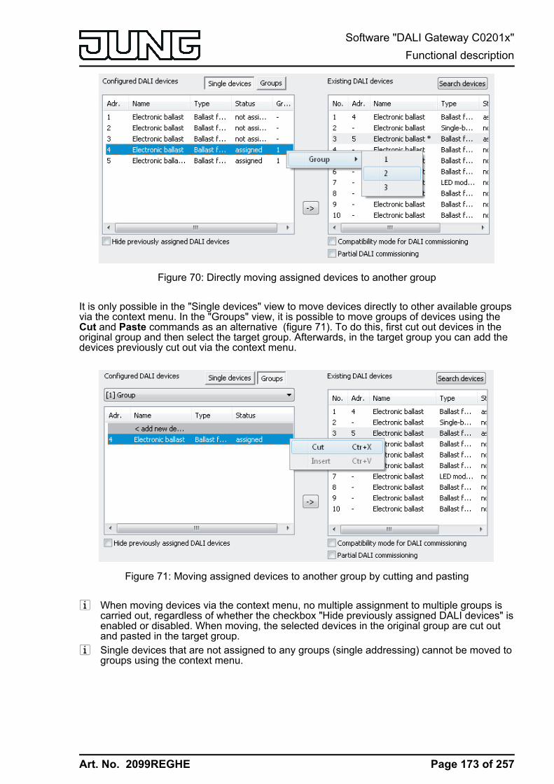
Art. No. 2099REGHE
Figure 70: Directly moving assigned devices to another group
It is only possible in the "Single devices" view to move devices directly to other available groupsvia the context menu. In the "Groups" view, it is possible to move groups of devices using theCut and Paste commands as an alternative (figure 71). To do this, first cut out devices in theoriginal group and then select the target group. Afterwards, in the target group you can add thedevices previously cut out via the context menu.
Figure 71: Moving assigned devices to another group by cutting and pasting
i When moving devices via the context menu, no multiple assignment to multiple groups iscarried out, regardless of whether the checkbox "Hide previously assigned DALI devices" isenabled or disabled. When moving, the selected devices in the original group are cut outand pasted in the target group.
i Single devices that are not assigned to any groups (single addressing) cannot be moved togroups using the context menu.
Page 173 of 257
Software "DALI Gateway C0201x"Functional description
Art. No. 2099REGHE
Assigning single devicesAs an alternative to the assignment of electronic ballasts to groups, it is possible to assign themto the devices of single addressing. The following sections document the individual actions to betaken to create a single device assignment in the DALI commissioning environment.i The assignment of DALI operating devices to single devices is only then possible when the
addressing type allows for device control.Assignment also takes place for single-addressed devices by moving the devices listed in theright-hand section into the left-hand section (view of all single devices). Assignment is carriedout by pressing the <- button between the two sections, or alternatively, by "drag and drop" withthe mouse. An assignment can be removed again by selecting an assigned operating deviceand, using the -> button or the mouse, shifting it back to the list box of available DALI devices.In contrast to the assignment of electronic ballasts to groups, it is not possible to assign multipleoperating devices simultaneously or to remove them from an assignment. Each electronicballast to be assigned requires a created single device in the Gateway project design so that thedevice name, the short address and, optionally, the DALI device type can be configured. Inorder to create an assignment, a created single device not previously assigned (status "Notassigned") must first be highlighted. After this, a found electronic ballast can be assigned to thissingle device using <-. Alternatively, assignment with the "drag and drop" function using themouse is possible.
Single devices can be deleted using the Del button on the PC keyboard and thus removed fromthe Gateway project design. The assignments to found electronic ballasts are also lost as aresult. The same applies if a single device is deleted in the configuration independently of theDALI commissioning dialog. In both cases, the plug-in warns of losing assignments.i DALI operating devices can either be integrated only in single device addressing, or
alternatively, in group addressing. It is not possible to control an operating device with bothaddressing types. Operating devices integrated in group control can no longer beaddressed as a single device. The reverse case applies in the same manner.
o In the left-hand section of the DALI commissioning environment, open the single deviceview and highlight the single device to be added to a found operating device.
o Then assign a found electronic ballast using <- or, alternatively, by "drag and drop" functionusing the mouse.In the right-hand section, the assigned operating devices disappear from the list box. Thestatus of the selected single device in the left-hand subarea switches to"Assigned".(figure 72). The right-hand pane contains only the remaining, not yet assignedoperating devices.
i If the checkbox "Hide previously assigned DALI devices" has been deselected in theCommissioning dialog of the plug-in, assigned electronic ballasts remain visible in the right-hand pane. Electronic ballasts assigned to programmed devices of the single addressing,cannot, however, be assigned to any other single devices (of the single or groupaddressing).
Page 174 of 257
Software "DALI Gateway C0201x"Functional description

Art. No. 2099REGHE
Figure 72: Operating device assigned to a programmed single device
o Reassign one of the remaining DALI operating devices to another programmed singledevice.In the right-hand section, the assigned operating device disappears from the list box. Thestatus of the selected single device in the left-hand subarea switches to "Assigned".
o Carry out assignments for other single devices as described if necessary.
i Pressing the Delete assignment button at the bottom edge of the commissioningenvironment allows deletion of all the assignments between the DALI operating devicesand the various single devices of the project design. The operation may take some time.The progress is displayed during the Delete operation. Long and short addresses as wellas other relevant parameters remain intact in the electronic ballasts.
i Pressing the Standard button deletes assignments of DALI operating devices toprogrammed single devices. Assignments of DALI operating devices are lost in the projectdesign and in the DALI Gateway when the "Standard" button is pressed in thecommissioning environment. The parameters of the DALI commissioning ("Hide previouslyassigned DALI devices", "Compatibility mode for DALI commissioning" and "Partial DALIcommissioning") are not reset here to the Standard configuration". These parametersalways remain at the states last set.
Optionally, the assignment of DALI operating devices to programmed single devices can besupplemented by testing of the DALI device types. If testing is enabled, the plug-in within thecourse of an assignment during online commissioning compares the device types determinedby the operating devices with the specifications by the device type parameters of the offlineconfiguration. Assignment can only take place if there is agreement. This will prevent functionalincompatibilities after commissioning. The testing of the device types is influenced by the "Use'DALI device type' setting ?" parameter in the parameter node "General".
Compatibility modeThe DALI Gateway has a compatibility mode for supporting non-DALI-conformant operatingdevices. This means that the commissioning process can become distinctly more toleranttowards specific DALI commissioning parameters, which means that operating devices not fully
Page 175 of 257
Software "DALI Gateway C0201x"Functional description
Art. No. 2099REGHE
compliant with the DALI specification can be commissioned, possibly subject to functionalrestrictions. Compatibility mode relates solely to DALI commissioning.Compatibility mode is activated when the checkbox "Compatibility mode for DALIcommissioning" (D) is selected in the DALI commissioning window of the ETS plug-in.(figure 63).
When compatibility mode is active, DALI operating devices in the system are no longeridentified using their previously programmed long address. Normally (when compatibility modeis deactivated), the Gateway uses the DALI long address to check if found operating deviceswere previously commissioned in a search operation (known device), or whether this is a newly-found electronic ballast. When the Gateway carries out a search operation for DALI operatingdevices, the long address is automatically assigned randomly and is programmed into theelectronic ballast. The long address is unique, thus allowing individual identification of operatingdevices.According to the DALI specification, all the DALI subscribers must save the long addresspermanently (e.g. even during mains voltage failures). Not all the DALI devices on the marketsupport this requirement, which is why difficulties may occur during the commissioning process.If long addresses are lost, the Gateway will no longer be able to identify clearly whether foundelectronic ballasts are known, i.e. already commissioned in previous commissioning operations,or whether they are newly-installed and are thus newly-found electronic ballasts. In these cases,operating devices are simply identified as "newly-found". As a result, during the remainder of thecommissioning process, the affected electronic ballasts are treated like unprogrammed devices.Amongst other things, all the assignments to groups or single devices are removed.If operating devices are installed in the DALI system, which do not comply with the DALIspecification - as described - and do not save the long address correctly, compatibility modeshould be activated. During a search operation, the Gateway then identifies solely by means ofthe DALI short address (1...64) contained in the devices. This address was either programmedduring a previous commissioning operation by the Gateway, in accordance to the projectdesign, or was assigned automatically during a search operation (new electronic ballast). Thismeans that electronic ballasts can be commissioned without accessing long addresses.i The identification of operating devices becomes problematic if devices are added to the
DALI installation at a later time, which were commissioned previously (e.g. in othersystems) and thus have already been assigned with valid short addresses. Here, it mayoccur that different electronic ballasts have the same short address. This state must beavoided when using compatibility mode, since short addresses may only occur once in aDALI installation. Otherwise, communication errors can be expected.
All the commissioning parameters transferred from the gateway are required for correct, fault-free operation of the DALI system and must correspond to the DALI specification. During onlinecommissioning, it may occur that all or some electronic ballasts do not apply the commissioningparameters transferred from the Gateway partially or completely. In order to detect this, thegateway in normal operation checks (compatibility mode deactivated) each programmedchange by reading it out and compares the return value of the operating devices with thespecifications in the project design (DALI verify). If differences are detected here among shortaddresses or group assignments to be programmed, the plug-in signals an error.DALI operating devices that could only be programmed with errors during the onlinecommissioning can work according to their function after commissioning is complete. TheseDALI operating devices possibly do not comply or only partially comply with DALI, however.If commissioning errors occur repeatedly, the compatibility mode can be activated on anexperimental basis. In compatibility mode the DALI gateway does not read back theprogrammed commissioning parameters during an online commissioning. Operating deviceswhich merely dispense with answering the gateway (DALI verify remains off / but the function isavailable), can be commissioned in this way without any error display and abort of theprogramming connection.If short addresses of the electronic ballasts change due to parameterisation or newassignments, the DALI gateway reprograms the addresses in the existing electronic ballasts. Ifcompatibility mode is deactivated, short addresses are changed by deleting the old one andrecording the new address. In rare cases, operating devices do not respond correctly to the
Page 176 of 257
Software "DALI Gateway C0201x"Functional description
Art. No. 2099REGHE
deletion of a short address. If the compatibility mode is activated, the short addresses istherefore not deleted. In this case, the gateway simply programs the new address over the oldone. Even in such cases, the compatibility mode helps to commission operating devicessmoothly that are not DALI-compliant.
Page 177 of 257
Software "DALI Gateway C0201x"Functional description
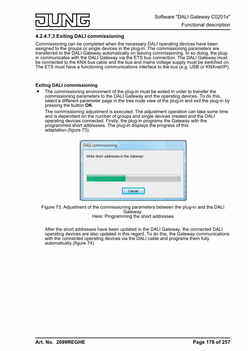
Art. No. 2099REGHE
4.2.4.7.3 Exiting DALI commissioningCommissioning can be completed when the necessary DALI operating devices have beenassigned to the groups or single devices in the plug-in. The commissioning parameters aretransferred to the DALI Gateway automatically on leaving commissioning. In so doing, the plug-in communicates with the DALI Gateway via the ETS bus connection. The DALI Gateway mustbe connected to the KNX bus cable and the bus and mains voltage supply must be switched on.The ETS must have a functioning communications interface to the bus (e.g. USB or KNXnet/IP).
Exiting DALI commissioningo The commissioning environment of the plug-in must be exited in order to transfer the
commissioning parameters to the DALI Gateway and the operating devices. To do this,select a different parameter page in the tree node view of the plug-in and exit the plug-in bypressing the button OK.The commissioning adjustment is executed. The adjustment operation can take some timeand is dependent on the number of groups and single devices created and the DALIoperating devices connected. Firstly, the plug-in programs the Gateway with theprogrammed short addresses. The plug-in displays the progress of thisadaptation.(figure 73).
Figure 73: Adjustment of the commissioning parameters between the plug-in and the DALIGateway.
Here: Programming the short addresses
After the short addresses have been updated in the DALI Gateway, the connected DALIoperating devices are also updated in this regard. To do this, the Gateway communicationswith the connected operating devices via the DALI cable and programs them fullyautomatically.(figure 74).
Page 178 of 257
Software "DALI Gateway C0201x"Functional description
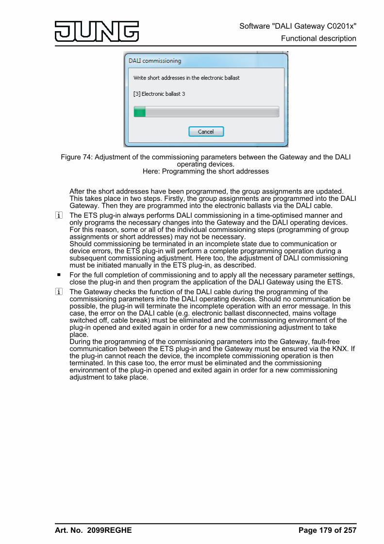
Art. No. 2099REGHE
Figure 74: Adjustment of the commissioning parameters between the Gateway and the DALIoperating devices.
Here: Programming the short addresses
After the short addresses have been programmed, the group assignments are updated.This takes place in two steps. Firstly, the group assignments are programmed into the DALIGateway. Then they are programmed into the electronic ballasts via the DALI cable.
i The ETS plug-in always performs DALI commissioning in a time-optimised manner andonly programs the necessary changes into the Gateway and the DALI operating devices.For this reason, some or all of the individual commissioning steps (programming of groupassignments or short addresses) may not be necessary.Should commissioning be terminated in an incomplete state due to communication ordevice errors, the ETS plug-in will perform a complete programming operation during asubsequent commissioning adjustment. Here too, the adjustment of DALI commissioningmust be initiated manually in the ETS plug-in, as described.
o For the full completion of commissioning and to apply all the necessary parameter settings,close the plug-in and then program the application of the DALI Gateway using the ETS.
i The Gateway checks the function of the DALI cable during the programming of thecommissioning parameters into the DALI operating devices. Should no communication bepossible, the plug-in will terminate the incomplete operation with an error message. In thiscase, the error on the DALI cable (e.g. electronic ballast disconnected, mains voltageswitched off, cable break) must be eliminated and the commissioning environment of theplug-in opened and exited again in order for a new commissioning adjustment to takeplace.During the programming of the commissioning parameters into the Gateway, fault-freecommunication between the ETS plug-in and the Gateway must be ensured via the KNX. Ifthe plug-in cannot reach the device, the incomplete commissioning operation is thenterminated. In this case too, the error must be eliminated and the commissioningenvironment of the plug-in opened and exited again in order for a new commissioningadjustment to take place.
Page 179 of 257
Software "DALI Gateway C0201x"Functional description
Art. No. 2099REGHE
i All the commissioning parameters transferred from the gateway are required for correct,fault-free operation of the DALI system and must correspond to the DALI specification.During online commissioning, it may occur that all or some electronic ballasts do not applythe commissioning parameters transferred from the Gateway partially or completely. Inorder to detect this, the Gateway checks each programmed change by reading it out andcompares the return value of the operating devices with the specifications in the projectdesign (DALI verify).If differences are detected here among group assignments that are to be programmed, thegateway logs the error internally and then continues the commissioning operation with thenext electronic ballast and also completes this one. At the end of the online commissioningadjustment, the plug-in displays a message listing all the electronic ballasts to which groupassignments could not be programmed successfully during commissioning.If the gateway detects differences among short addresses to be programmed, it terminatesthe commissioning immediately with an error message. Short addresses are absolutelyessential for the operation of a DALI system. If commissioning errors occur here, thegateway cannot ensure smooth operation of the DALI installation. Consequently, it is thennecessary to abort the online commissioning.DALI operating devices that could only be programmed with errors during the onlinecommissioning can work according to their function after commissioning is complete.These DALI operating devices possibly do not comply or only partially comply with DALI,however. Please contact the manufacturer of the electronic ballasts concerned to clarifyany functional incompatibilities.If commissioning errors occur repeatedly, the DALI compatibility mode can be activated onan experimental basis (see page 175). In compatibility mode the DALI gateway does notread back the programmed commissioning parameters during an online commissioning.Operating devices which merely dispense with answering the gateway (DALI verify remainsoff / but the function is available), can be commissioned in this way without any errordisplay and abort of the programming connection.
i When the commissioning environment is exited, the commissioning parameters (identifiedoperating devices with long and short address, names of the operating devices,group/device assignment and device type) are written to the ETS database and are thussaved. The saved data is displayed the next time the commissioning environment isstarted.
i If just assignments of programmed devices of the single addressing (i.e. no groupassignments) are removed and no short addresses are changed during a commissioningsession, then no adjustment will be performed between the ETS plug-in, the Gateway andthe operating devices when the commissioning environment is exited. This means that themost-recently programmed short addresses are retained in the electronic ballast (unusedshort addresses). In the case of a new commissioning operation, however, the affectedelectronic ballasts can again be assigned and commissioned normally.
i Pressing the Delete assignment button at the bottom edge of the commissioningenvironment allows deletion of all the assignments between the DALI operating devicesand the various groups and single devices. Not only are the assignments reset in the plug-in, but there is also an adjustment of the commissioning parameters of the DALI Gateway.For this purpose, the plug-in sets up communication to the DALI Gateway via the busconnection of the ETS and deletes all the assignments in the device memory there. Theoperation may take some time. The progress is displayed during the Delete operation. Ifthe bus communication is faulty, the plug-in terminates the operation without deleting theassignments in the project design or in the device. Previously identified DALI operatingdevices remain intact, but without group/device assignments.
Page 180 of 257
Software "DALI Gateway C0201x"Functional description
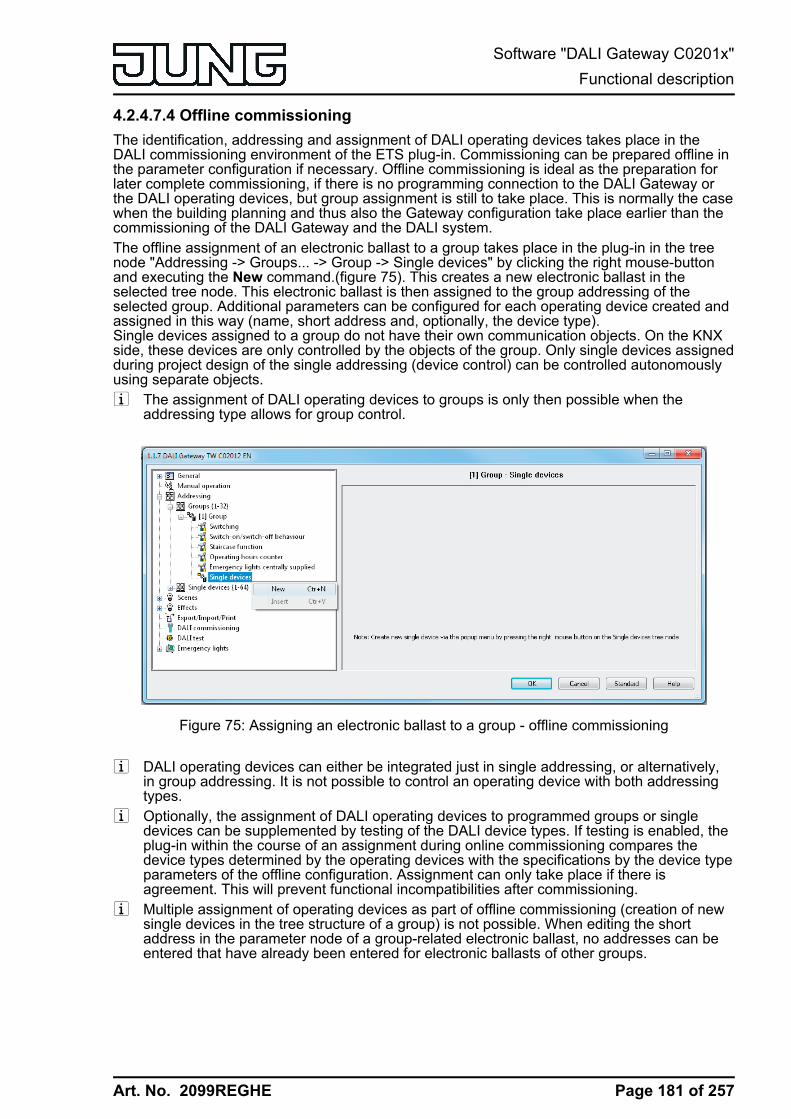
Art. No. 2099REGHE
4.2.4.7.4 Offline commissioningThe identification, addressing and assignment of DALI operating devices takes place in theDALI commissioning environment of the ETS plug-in. Commissioning can be prepared offline inthe parameter configuration if necessary. Offline commissioning is ideal as the preparation forlater complete commissioning, if there is no programming connection to the DALI Gateway orthe DALI operating devices, but group assignment is still to take place. This is normally the casewhen the building planning and thus also the Gateway configuration take place earlier than thecommissioning of the DALI Gateway and the DALI system.The offline assignment of an electronic ballast to a group takes place in the plug-in in the treenode "Addressing -> Groups... -> Group -> Single devices" by clicking the right mouse-buttonand executing the New command.(figure 75). This creates a new electronic ballast in theselected tree node. This electronic ballast is then assigned to the group addressing of theselected group. Additional parameters can be configured for each operating device created andassigned in this way (name, short address and, optionally, the device type).Single devices assigned to a group do not have their own communication objects. On the KNXside, these devices are only controlled by the objects of the group. Only single devices assignedduring project design of the single addressing (device control) can be controlled autonomouslyusing separate objects.i The assignment of DALI operating devices to groups is only then possible when the
addressing type allows for group control.
Figure 75: Assigning an electronic ballast to a group - offline commissioning
i DALI operating devices can either be integrated just in single addressing, or alternatively,in group addressing. It is not possible to control an operating device with both addressingtypes.
i Optionally, the assignment of DALI operating devices to programmed groups or singledevices can be supplemented by testing of the DALI device types. If testing is enabled, theplug-in within the course of an assignment during online commissioning compares thedevice types determined by the operating devices with the specifications by the device typeparameters of the offline configuration. Assignment can only take place if there isagreement. This will prevent functional incompatibilities after commissioning.
i Multiple assignment of operating devices as part of offline commissioning (creation of newsingle devices in the tree structure of a group) is not possible. When editing the shortaddress in the parameter node of a group-related electronic ballast, no addresses can beentered that have already been entered for electronic ballasts of other groups.
Page 181 of 257
Software "DALI Gateway C0201x"Functional description
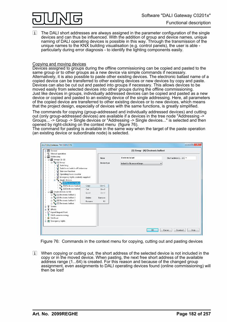
Art. No. 2099REGHE
i The DALI short addresses are always assigned in the parameter configuration of the singledevices and can thus be influenced. With the addition of group and device names, uniquenaming of DALI operating devices is possible in this way. Through the transmission of theunique names to the KNX building visualisation (e.g. control panels), the user is able -particularly during error diagnosis - to identify the lighting components easily.
Copying and moving devicesDevices assigned to groups during the offline commissioning can be copied and pasted to thesame group or to other groups as a new device via simple commands if necessary.Alternatively, it is also possible to paste other existing devices. The electronic ballast name of acopied device can be transferred to other existing devices or new devices by copy and paste.Devices can also be cut out and pasted into groups if necessary. This allows devices to bemoved easily from selected devices into other groups during the offline commissioning.Just like devices in groups, individually addressed devices can be copied and pasted as a newdevice or copied and pasted to an existing device of the single addressing. Here, all parametersof the copied device are transferred to other existing devices or to new devices, which meansthat the project design, especially of devices with the same functions, is greatly simplified.The commands for copying (group-addressed and individually addressed devices) and cuttingout (only group-addressed devices) are available if a devices in the tree node "Addressing ->Groups... -> Group -> Single devices or "Addressing -> Single devices..." is selected and thenopened by right-clicking on the context menu (figure 76).The command for pasting is available in the same way when the target of the paste operation(an existing device or subordinate node) is selected.
Figure 76: Commands in the context menu for copying, cutting out and pasting devices
i When copying or cutting out, the short address of the selected device is not included in thecopy or in the moved device. When pasting, the next free short address of the availableaddress range (1...64) is created. For this reason and because of the changed groupassignment, even assignments to DALI operating devices found (online commissioning) willthen be lost!
Page 182 of 257
Software "DALI Gateway C0201x"Functional description
Art. No. 2099REGHE
i As an alternative to moving a group-addressed device via the context menu (cutting andpasting), devices can also be moved between groups by "drag and drop" with the mouse.In contrast to moving via the commands of the context menu, the short addresses of thedevices are retained when moving with the mouse. Owing to the changed groupassignment, even assignments to DALI operating devices found (online commissioning) willbe lost here, too!
i Devices that are copied or cut out can also be pasted multiple times.i It is not possible to paste devices from the group assignment into an individually addressed
device or into the individually addressed area. It is not possible to paste or move anindividually addressed device into the group area either.
Page 183 of 257
Software "DALI Gateway C0201x"Functional description

Art. No. 2099REGHE
4.2.4.7.5 Troubleshooting
KNX communication errorDuring the online commissioning, the short addresses of the electronic ballasts and groupassignments are programmed into the gateway and DALI operating devices. For this purpose,the plug-in establishes a programming connection to the DALI gateway via the active datainterface of the ETS. In the later course, the gateway establishes a programming connection tothe DALI operating devices.During the programming of the commissioning parameters into the Gateway, fault-freecommunication between the ETS plug-in and the Gateway must be ensured via the KNX.If the plug-in cannot reach the DALI gateway via the KNX programming connections of the ETS,the incomplete commissioning operation is then aborted immediately. The plug-in then displaysan error (figure 77). In this case, the error must be removed and the DALI commissioning mustbe repeated.
Figure 77: KNX communication problem error message
Errors with the KNX communication during DALI commissioning are normally due to redundanttelegram repetitions or wrong telegram sequences. Other bus devices or ETS installations onPC, which are utilized to capacity with regard to the available memory and/or processorresources, are frequently the cause here. In the event of a error, area couplers or line couplersare normally available in the KNX installation.If the described communication errors occur in a KNX system, the configuration of the areacoupler or line coupler should be changed temporarily as a remedy. Switching off the telegramrepetitions in the event of transmission errors in the couplers frequently allows KNXcommunication to take place smoothly between the ETS and gateway.
Recommended Procedure...- Reconfiguration of all area / line couplers affected. Couplers are affected when they are
directly in the lines of the ETS and DALI gateways or in the communication channelbetween them.Switching off the telegram repetitions by the couplers. To do this, set the couplerparameters "Repetitions in case of transmission errors..." of all addressing types to "no".These parameters are normally set to "yes" in the presetting of the couplers.Programming the application program of the couplers.
- Executing the DALI commissioning using the plug-ins of the gateway.- After completion of the DALI commissioning, reset the parameters "Repetitions in case of
transmission errors..." of all addressing types in all couplers affected to the original setting(normally to "yes").Programming the application program of the couplers.
i The telegram repetitions should also then be switched off temporarily when communicationbetween the ETS and DALI gateway does not take place across all lines.
Page 184 of 257
Software "DALI Gateway C0201x"Functional description
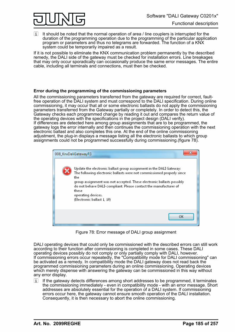
Art. No. 2099REGHE
i It should be noted that the normal operation of area / line couplers is interrupted for theduration of the programming operation due to the programming of the particular applicationprogram or parameters and thus no telegrams are forwarded. The function of a KNXsystem could be temporarily impaired as a result.
If it is not possible to eliminate the KNX communication problem permanently by the describedremedy, the DALI side of the gateway must be checked for installation errors. Line breakagesthat may only occur sporadically can occasionally produce the same error messages. The entirecable, including all terminals and connections, must then be checked.
Error during the programming of the commissioning parametersAll the commissioning parameters transferred from the gateway are required for correct, fault-free operation of the DALI system and must correspond to the DALI specification. During onlinecommissioning, it may occur that all or some electronic ballasts do not apply the commissioningparameters transferred from the Gateway partially or completely. In order to detect this, theGateway checks each programmed change by reading it out and compares the return value ofthe operating devices with the specifications in the project design (DALI verify).If differences are detected here among group assignments that are to be programmed, thegateway logs the error internally and then continues the commissioning operation with the nextelectronic ballast and also completes this one. At the end of the online commissioningadjustment, the plug-in displays a message listing all the electronic ballasts to which groupassignments could not be programmed successfully during commissioning.(figure 78).
Figure 78: Error message of DALI group assignment
DALI operating devices that could only be commissioned with the described errors can still workaccording to their function after commissioning is completed in some cases. These DALIoperating devices possibly do not comply or only partially comply with DALI, however.If commissioning errors occur repeatedly, the "Compatibility mode for DALI commissioning" canbe activated as a remedy. In compatibility mode the DALI gateway does not read back theprogrammed commissioning parameters during an online commissioning. Operating deviceswhich merely dispense with answering the gateway can be commissioned in this way withoutany error display.i If the gateway detects differences among short addresses to be programmed, it terminates
the commissioning immediately - even in compatibility mode - with an error message. Shortaddresses are absolutely essential for the operation of a DALI system. If commissioningerrors occur here, the gateway cannot ensure smooth operation of the DALI installation.Consequently, it is then necessary to abort the online commissioning.
Page 185 of 257
Software "DALI Gateway C0201x"Functional description

Art. No. 2099REGHE
i If the described DALI commissioning faults occur permanently, a DALI reset should beperformed using the plug-in ("Reset" button in the commissioning dialogue). As a result, allDALI operating devices will be reset to the delivery states defined by the manufacturers. Inthis operation, all the assignments to groups and single devices in the electronic ballastsare removed. Furthermore, the long and short addresses in the operating devices aredeleted.
If it is not possible to eliminate the error message permanently by the compatibility mode, theDALI side of the gateway must be checked for installation errors. Line breakages that may onlyoccur sporadically can occasionally produce the same error messages. The entire cable,including all terminals and connections, must then be checked.
Page 186 of 257
Software "DALI Gateway C0201x"Functional description

Art. No. 2099REGHE
4.2.4.8 DALI test
Starting DALI testThe plug-in of the DALI Gateway offers various options for carrying out a comprehensive test ofthe DALI installation. This means that after DALI commissioning, it is possible to controlindividual operating devices in a device-orientated test, to switch them and to read out or specifybrightness values or colour temperature values. The individual device status can also bedisplayed. In the group-orientated test, all the created DALI groups (1...32) can be switchedseparately, changed in the brightness value or in the colour temperature (if supported by theoperating device). In addition, it is possible to check the function of the configured scenes(1...16) and effects (1...16).The DALI test can only be performed if the device, group, effect and scene configuration in theDALI Gateway remains current after DALI commissioning or parameters are changed. For thisreason, it is necessary to program the DALI Gateway with the ETS before a DALI test ifchanges were previously made to the device configuration (see page 13).If the necessary requirements have been fulfilled, the "DALI test" can be executed on theparameter page of the same name in the plug-in. After selecting the test page and successfulcommunication with the DALI Gateway, the commissioning environment becomes visible in theright-hand pane of the plug-in.i In the course of a DALI test, only broadcast commands (switch all devices) can be issued,
provided that addressing allows for central control.
Figure 79: DALI test environment in the ETS plug-in
When the test environment is recalled, the plug-in first tries to communicate with the ETS via thebus connection, and checks whether a DALI test is possible. For this reason, the DALI Gatewaymust be connected to the KNX bus cable and the bus and mains voltage supply must beswitched on when the DALI test is recalled. In addition, the ETS must have a functioningcommunications interface to the bus (e.g. USB or KNXnet/IP).
If it is not possible to set up a connection to the DALI Gateway in this situation, the plug-in thenterminates the test and does not display the test environment. The following section lists thecauses for a faulty connection and the appropriate remedies...- Cause: No functioning ETS communication interface to the KNX.
Remedy: Check, and if necessary, setup the connection in the ETS.
Page 187 of 257
Software "DALI Gateway C0201x"Functional description

Art. No. 2099REGHE
- Cause: Physical address and application program not previously programmed by the ETS.Remedy: Close the plug-in and first program the physical address and application program.
- Cause: KNX bus voltage on the DALI Gateway or the local data interface not connected orswitched on.Remedy: Connect and switch on the bus voltage.
- Cause: Mains voltage supply on the DALI Gateway not switched on.Remedy: Switch on the mains supply on the Gateway.
Device-orientated DALI testAs soon as DALI commissioning has taken place, and operating devices have thus also beidentified and assigned, the correct function of these devices can be tested in the device-orientated DALI test. The device-orientated test environment is used for this.(figure 80).
Figure 80: Device-orientated DALI test environment
The operating device to be tested must first be selected in the "Device" selection box. Thiscontains all the identified and assigned DALI operating devices - indicated by the individualshort address in square brackets and the device name. Only one device can be tested at a time.The selected operating device can then be switched on or off independently. In addition, it ispossible to specify an absolute brightness value or colour temperature value.Pressing the "Set value" button in the "brightness value" area transmits the brightness valueselected in the selection box to the appropriate operating device, which should then set itselfimmediately to this brightness value. The brightness value is independent of a configuration forminimum or maximum brightness. The whole brightness range can thus be set in the device-orientated DALI test. Similarly, the currently set brightness value of the DALI operating devicecan be polled by pressing the "Read out value" button in the "brightness value" area. The read-out value is displayed in the selection box above.As with the brightness test of a DALI operating device, the colour temperature in the selectionbox is transmitted to the corresponding operating device when the "Set value" button is pressedin the "colour temperature" area. The electronic ballast should then adjust itself immediately tothe specified colour temperature, but only if the luminaire is also switched on. The colour
Page 188 of 257
Software "DALI Gateway C0201x"Functional description
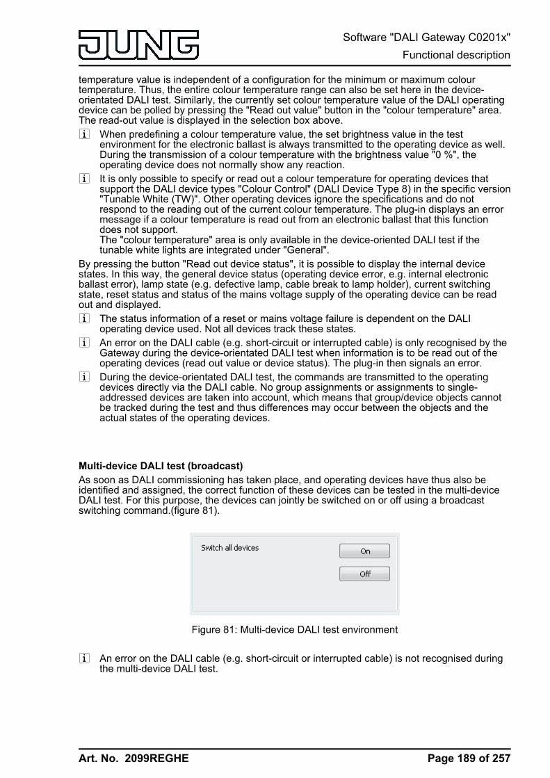
Art. No. 2099REGHE
temperature value is independent of a configuration for the minimum or maximum colourtemperature. Thus, the entire colour temperature range can also be set here in the device-orientated DALI test. Similarly, the currently set colour temperature value of the DALI operatingdevice can be polled by pressing the "Read out value" button in the "colour temperature" area.The read-out value is displayed in the selection box above.i When predefining a colour temperature value, the set brightness value in the test
environment for the electronic ballast is always transmitted to the operating device as well.During the transmission of a colour temperature with the brightness value "0 %", theoperating device does not normally show any reaction.
i It is only possible to specify or read out a colour temperature for operating devices thatsupport the DALI device types "Colour Control" (DALI Device Type 8) in the specific version"Tunable White (TW)". Other operating devices ignore the specifications and do notrespond to the reading out of the current colour temperature. The plug-in displays an errormessage if a colour temperature is read out from an electronic ballast that this functiondoes not support.The "colour temperature" area is only available in the device-oriented DALI test if thetunable white lights are integrated under "General".
By pressing the button "Read out device status", it is possible to display the internal devicestates. In this way, the general device status (operating device error, e.g. internal electronicballast error), lamp state (e.g. defective lamp, cable break to lamp holder), current switchingstate, reset status and status of the mains voltage supply of the operating device can be readout and displayed.i The status information of a reset or mains voltage failure is dependent on the DALI
operating device used. Not all devices track these states.i An error on the DALI cable (e.g. short-circuit or interrupted cable) is only recognised by the
Gateway during the device-orientated DALI test when information is to be read out of theoperating devices (read out value or device status). The plug-in then signals an error.
i During the device-orientated DALI test, the commands are transmitted to the operatingdevices directly via the DALI cable. No group assignments or assignments to single-addressed devices are taken into account, which means that group/device objects cannotbe tracked during the test and thus differences may occur between the objects and theactual states of the operating devices.
Multi-device DALI test (broadcast)As soon as DALI commissioning has taken place, and operating devices have thus also beidentified and assigned, the correct function of these devices can be tested in the multi-deviceDALI test. For this purpose, the devices can jointly be switched on or off using a broadcastswitching command.(figure 81).
Figure 81: Multi-device DALI test environment
i An error on the DALI cable (e.g. short-circuit or interrupted cable) is not recognised duringthe multi-device DALI test.
Page 189 of 257
Software "DALI Gateway C0201x"Functional description

Art. No. 2099REGHE
i During the multi-device DALI test, the commands are forwarded to the operating devicesdirectly using the DALI cable. No group assignments or assignments to single-addresseddevices are taken into account, which means that group/device objects cannot be trackedduring the test and thus differences may occur between the objects and the actual states ofthe operating devices.
Testing groupsThe group-orientated DALI test can be carried out as soon as groups have been created andconfigured in the device configuration and DALI commissioning has been carried out with thegroup assignment of the operating devices. To do this, press the button "Test DALI groups" inthe DALI test environment. The group-orientated test environment then opens.(figure 82).
Figure 82: Group-orientated DALI test environment (as an example with three created groups)
For reasons of clarity, the possible groups (1...32) are spread over two pages, which can beshown separately. Pressing the buttons "Groups 1-16" and "Groups 17-32" at the top edge ofthe window changes between the page views. Only those groups which have been created inthe device configuration can be set and thus tested. Any non-created groups are greyed out.In the group-orientated DALI test, each group can independently be switched on or off, ordimmed absolutely or relatively. Pressing the buttons "On" or "Off" causes immediate switchingof the operating devices assigned to the appropriate group.Alternatively, an absolute brightness value can be specified, which can be transmitted to theoperating devices of the group by pressing the button "Set" next to it. The brightness value isdependent on the group configuration for minimum or maximum brightness. Thus, it may occurthat only a limited brightness range can be set in the group-orientated DALI test.Similarly, the currently set brightness value of the group can be polled by pressing the "Read"button. The read-out value is displayed in the selection box alongside. Due to rounding, the
Page 190 of 257
Software "DALI Gateway C0201x"Functional description
Art. No. 2099REGHE
displayed value may deviate slightly from that most recently specified.In addition, the operating devices of the group can be dimmed relatively. Pressing the "Start"button initiates a relative dimming operation of the group. The dimming operation takes placewithin the brightness range specified for the group using the configured dimming speed, startingwith the currently set brightness value. A relative dimming operation can be stopped by pressingthe "Stop" button. Reactivation of a dimming operation using the "Start" button causes dimmingto take place in the reverse direction. Relative dimming to 0 % brightness (OFF) is not possible.As with the brightness test of a DALI group, a colour temperature can also be tested group-oriented. When the "set" button is pressed, the colour temperature in the selection box next to itis transmitted. The group should then adjust itself immediately to the specified colourtemperature, but only if the group is also switched on. Just like the brightness, the colourtemperature value is dependent on the configuration for the minimum or maximum colourtemperature of the relevant group. Thus, it might only be possible even here to set a limitedcolour temperature range in the group-orientated DALI test. Optionally, the currently set colourtemperature value of the DALI group can be polled by pressing the "Read" button. The read-outvalue is displayed in the selection box of the colour temperature.i A colour temperature value set in the group-oriented test environment is only ever
transmitted to the DALI group if the group is switched on (brightness > 0 %). When settinga colour temperature in the "OFF" state (brightness value = 0 %), the operating devices donot show any reaction unless the group should switch on in the "OFF" state whenpredefining a colour temperature (configurable function of the group).
i The specification or reading out of a colour temperature only shows a reaction if operatingdevices are integrated into the group that support the DALI device types "Colour Control"(DALI Device Type 8) in the specific version "Tunable White (TW)". Other operatingdevices ignore the specifications and do not respond to the reading out of the currentcolour temperature. The "colour temperature" range is only available in the group-orientedDALI test if the tunable white lights are integrated under "General".
i An error on the DALI cable (e.g. short-circuit or interrupted cable) is not recognised duringthe group-orientated DALI test.
i In the group-oriented DALI test, operating devices of the group respond to the switchingand brightness and colour temperature value specifications as stipulated in theconfiguration. All the actions are implemented internally using the appropriate KNX objectsof the groups and individual devices. Thus, the internal object values can be read out, forexample, when the brightness values are read out and the switching object describedinternally when a group is switched on. Here, feedback is also generated and theappropriate DALI group parameters included. If no operating device was assigned to thegroups during DALI commissioning, there will be no visible reaction in the DALI system.
i DALI operating devices assigned to multiple groups always set themselves to the mostrecent status set using one of the assigned groups. In this case, feedback of the switchingstatus, brightness value or colour temperature of a group cannot always be clear.Example 1: Group 2 is set to 10 % brightness. After this, Group 3 is dimmed to 20 %brightness. The lights of Group 3 assume the most recently recalled brightness value: 20%. The feedback of Group 2 remains at 10 %, although some of the operating devicesbelonging to the group were set to 20 % brightness.Example 2: Group 2 is switched on and sets itself to the brightness value 100 %. Thestatus of Group 3 internally in the DALI Gateway remains at 0 % brightness (OFF). NowGroup 3 is made brighter. The lights of Group 3 adopt the dimming behaviour (becomingbrighter from minimum brightness), although these lights have already been switched on byGroup 2.
Testing scenesThe scene-orientated DALI test can be carried out once scenes have been created andconfigured in the device configuration and DALI commissioning has been carried out with thegroup/device assignment of the operating devices. To do this, press the button "Test DALIscenes" in the DALI test environment. The scene-orientated test environment thenopens.(figure 83). Not only the groups and single devices integrated into the scenes can be
Page 191 of 257
Software "DALI Gateway C0201x"Functional description

Art. No. 2099REGHE
tested in the scene test. Of more importance is the fact that a scene definition is also possiblethrough reading out and saving scene values.
Figure 83: Scene-orientated DALI test environment (as an example with Scene 1 with threecreated groups)
The scene to be tested must first be selected. To do this, select one of the scenes created in thedevice configuration in the "Scene" selection box. After selecting the scene, the assignedgroups and single devices can be edited. For reasons of clarity, the possible groups (1...32) andsingle devices (1...64) are spread over multiple pages, which can be shown separately.Pressing the buttons "Groups..." or "Single devices..." at the top edge of the window changesbetween the page views. Only the groups and single devices can be edited (and thus tested),which are assigned to the scene. Any non-assigned groups or single devices are greyed out.When starting the scene-orientated DALI test, the predefined brightness values and colourtemperature values (only when using the colour temperature control) in the scene configuration(parameter page "Scenes") are visible in the appropriate selection boxes. Pressing the button"Recall" scene causes a scene recall with the values predefined in the scene configuration. Theset brightness values and colour temperature values in the group/device selection boxes of thetest environment are not important.The values specified in the test environment are only applied and saved to the sceneconfiguration of the plug-in and the DALI Gateway when the button "Save scene" is pressed.The original values predefined in the scene configuration are overwritten.Before new brightness values and colour temperature values are saved for a scene, it ispossible to read out the values currently set in the groups and single devices. The read-outvalues are displayed in the selection boxes and can be edited and finally saved in the scene.
Page 192 of 257
Software "DALI Gateway C0201x"Functional description

Art. No. 2099REGHE
i The test functions for the colour temperature are only available if integration of the tunablewhite lights is provided under "General". If the colour temperature control is used globally,the plug-in always displays test functions for the colour temperature for all groups andsingle devices in all scenes, too. This is displayed even if no colour temperature control atall is provided in the groups or single devices (e.g. in the case of DALI device types that donot even allow any colour temperature control). In such cases, the colour temperaturespecifications in the scenes are ineffective.
i An error on the DALI cable (e.g. short-circuit or interrupted cable) is not recognised duringthe scene-orientated DALI test.
i In the scene-orientated DALI test, all the actions are implemented internally using theappropriate KNX objects of the groups and individual devices. Thus, the internal objectvalues can be read out when the brightness values are read out, for example. On scenerecall, feedback to the KNX is also transmitted. If no operating device was assigned to theprogrammed groups and single devices during DALI commissioning, then there will be novisible reaction in the DALI system.
i If a DALI operating device is assigned to multiple groups and these groups were assignedto a scene, then the brightness values and colour temperature values of the group with thehighest group number are recalled or saved for the multiple-assigned devices. In this case,feedback of the switching status, brightness value or colour temperature of a group cannotalways be clear.
Testing effectsThe DALI test for effects can be carried out as soon as effects have been created andconfigured in the device configuration and DALI commissioning has been carried out with thegroup/device assignment of the operating devices. To do this, press the button "Test DALIeffects" in the DALI test environment. The effect test environment then opens.(figure 84).
Figure 84: DALI test environment for effects
Even when testing effects, the effect to be tested must first be chosen. To do this, select one ofthe effects created in the device configuration in the "Effect" selection box. After effect selection,the selected effect can be started or stopped by pressing the appropriate buttons in the testdialog. An effect started using the test dialog runs according to its configuration. The steps arerecalled in sequence starting with step 1. The number of effect run-throughs, the dimmingbehaviour when an effect step is recalled and the delay until the next step are all maintained.The stop step is recalled when an effect is stopped using the DALI test.The "Single step" button can be pressed to test individual effect steps. Here, the Gatewayswitches exactly one step forward from the current stop of an effect. We recommend only usingthe single step function for stopped effects. This allows free switching of entire effect run-throughs.When the single step function is used, a stopped effect starts with the first step of the effect. Thesubsequent effect steps are then recalled continuously according to their number. The stop step(last step of an effect) can also be recalled using the single step function.
Page 193 of 257
Software "DALI Gateway C0201x"Functional description

Art. No. 2099REGHE
The test dialog provides status information on the current step and the current run-through of aneffect. In addition, the total number of all steps and run-throughs is displayed. In the display box"Step (current/total)", the left-hand number signals the number of the effect step currently set.The right-hand number provides information on the maximum number of steps available in theeffect (including the stop step). When an effect step is recalled using the single step function,"..." is displayed on the panel screen. This display goes out if the controller has set all therequired brightness values or colour temperature values of the manually recalled effect on theDALI operating devices. The delay until the next effect step specified in the configuration isirrelevant.In the display box "Run-through (current/total)", the left-hand number shows the number of thecurrent effect run-through. The right-hand number signals the maximum number of all effect run-throughs according to the configuration (the number "0" means that the run-through is set asinfinite).i It should be noted that the status information in the display boxes during automatic control
are only updated cyclically approx. every 3 seconds. With rapid effect run-throughs, it mayoccur that individual steps or even entire run-throughs are skipped in the display.
The run-through of a running effect can optionally be accelerated in the DALI test. An"Accelerate run-through" button and an input box whose setting specifies the acceleration factor(1x to 10x) are provided for this purpose. With this function it is also possible to test slow effectrun-throughs without having to wait for the real-time effect step transitions.When the button "Accelerate run-through" is pressed, the run-through is accelerated by thespecified factor, i.e. the "Delay until next step" programmed into the Gateway for each step. Thespecification applies to the whole effect, i.e. for all the set delay times of all the effect steps.i It should be noted that the acceleration factor only influences the configured delay times
which are executed after successfully addressing all the groups, single devices or scenesintegrated into the effect step. The time needed by the individual effect controller to executethe addressing operation itself is not influenced by the acceleration. The more singledevices that are integrated into an effect step, the longer the addressing operation and thetime not influenced by the acceleration will be.
i Only small acceleration factors should be used for short delay times up to the next effectsteps (< 10 s) or longer dimming times, if at all. Otherwise, the effect run-through will begreatly distorted.
i An error on the DALI cable (e.g. short-circuit or interrupted cable) is not recognised duringthe effect test.
Page 194 of 257
Software "DALI Gateway C0201x"Functional description

Art. No. 2099REGHE
4.2.4.9 Delivery stateIn the Delivery state of the DALI Gateway, the device is passive, i.e. no telegrams aretransmitted to the bus. Joint operation of the connected DALI operating devices by broadcastmanual operation on the device, if the mains voltage is on. In the manual control mode, nofeedback telegrams are sent to the bus. Other functions of the Gateway are deactivated.The device can be programmed and put into operation via the ETS (if the bus and mainsvoltage supply are connected and switched on). The physical address is preset to 15.15.255
Furthermore, the device has been configured at the factory with the following characteristics...- Manual operation: broadcast- Dimming speed, manual operation (0 %...100 %): 3.5 seconds- Minimum brightness 0.1 %- Maximum brightness 100 %- Response to bus voltage failure: No reaction.- Response to bus voltage return: No reaction.- Response after return of the mains voltage supply on the DALI Gateway: No reaction from
the DALI Gateway. (On the return of mains voltage, the DALI operating devices usuallyinitialise themselves to the most recently programmed "Power-On Level".)
i The delivery state (broadcast manual operation) can be restored at any time by unloadingthe application program using the ETS.
i In the delivery state, no colour temperature control is possible.
Page 195 of 257
Software "DALI Gateway C0201x"Functional description

Art. No. 2099REGHE
4.2.5 Parameters
4.2.5.1 General parameters
Description Values Commenth GeneralEnable DALI devicereplacement throughmanual operation ?
no
yes
After starting the automatic devicereplacement, the DALI Gateway is ableto check the completeness of the DALIoperating devices integrated into thesystem through a manual operation onthe device. The DALI Gateway detectsindividual replaced electronic ballastsand can program these devices with theappropriate programming data. Only ifthis parameter is set to "yes" is itpossible to initiate automatic devicereplacement through a manual operationlocally on the device (press the buttonsc and ALL OFF simultaneously for atleast 10 seconds). If set to "no", amanual operation for devicereplacement will produce no reaction.
Blinking rate 1 sec2 sec5 sec10 sec
Groups or single devices can also beconfigured as "flashing" at the beginningor at the end of a disabling function, ifused. In this case, the appropriateoperating devices change their switchingstate cyclically. The parameter "Flashingrate" generally defines the switch-ontime and switch-off time of a flashingmessage for all groups and devices.
Example:Flashing rate = 1 s1 sec. on -> 1 sec. off -> 1 sec. on -> 1sec off ...
Central function ? no
yes
The "yes" setting enables the centralfunction and thus the "Central function"object. An assignment of DALI groups orsingle devices to the central function isonly possible if the function is enabled.
Central object polarity 0 = deactivated /1 = activated
1 = deactivated /0 = activated
This parameter defines the polarity ofthe central object. This parameter isvisible only if the central function isenabled.
Use setting "DALIdevice type" ?
no
yes
Optionally, the assignment of DALIoperating devices to programmedgroups or single devices can besupplemented by testing of the DALI
Page 196 of 257
Software "DALI Gateway C0201x"Parameters

Art. No. 2099REGHE
device types. If testing is enabled, theplug-in compares, during assignment aspart of commissioning, the device typesdetermined by the operating deviceswith the specifications by the devicetype parameters. Assignment can onlytake place if there is agreement. Thiswill prevent functional incompatibilitiesafter commissioning.The function for testing the DALI devicetypes is enabled by this parameter whenit is set to "yes".
Integrate emergencylights ?
no
yes
The DALI Gateway can be integratedinto DALI emergency lighting systems. Itallows interference-free operation ofoperating devices, general lightingsystems and emergency lightingoperating devices of the same DALIsystem. The "Emergency lighting"function is enabled if this parameter isset to "yes". In this case, the parameternode "Emergency lights", which containsall the relevant parameters forconfiguring the emergency lightingfunction, becomes visible.
Integration of tunablewhite luminaires (TW /DALI device type 8)?
no
yes
The DALI Gateway supports the controlof DALI operating devices of the devicetype "Colour Control" (DALI Device Type8) in the specific version"Tunable White (TW)". This makes itpossible to control the colourtemperature of a lamp by means ofsuitable DALI operating devices andluminaires.The use of the colour temperaturecontrol can be centrally enabled here.
Use device type for TWluminaires?
yes If the colour temperature control is used,the ETS plug-in of the Gateway checksthe DALI device type indicated by theinstalled operating device (electronicballast found) as part of the deviceassignment during DALI commissioning.Testing of the DALI device type is thenessential and subsequently cannot beswitched off in the ETS plug-in. For thisreason, this parameter cannot be edited.The parameter is only then visible if TWluminaires are integrated and theparameter "Use 'DALI device type'setting ?" is configured to "no".
h General -> DALI communication
Page 197 of 257
Software "DALI Gateway C0201x"Parameters
Art. No. 2099REGHE
Activate DALI telegramratelimit ?
no
yes
The DALI telegram rate limit canoptionally be activated ("yes" setting).Firstly, it is then possible to extend theperiod of time between DALI telegrams.Secondly, the initialisation behaviour ofthe Gateway can be influenced. Byusing the DALI telegram rate limit, it ispossible to adapt the communicationbehaviour of the Gateway to problematicor non-DALI-conformant operatingdevices to a great extent.
Minimum time delaybetween two DALItelegrams(1...5 x 9.15 ms)
1.01.52.02.53.03.54.04.55.0
In accordance with the valid DALIstandard, pauses of at least 9.15 msmust be maintained between thetransmissions of individual DALItelegrams to the operating devices.Optionally, to reduce the telegram loadfor the DALI operating devices, and thusreduce the likelihood of errors on thepart of some electronic ballasts, it ispossible to increase the pause timebetween telegrams of the DALI Gatewayto the operation device by a multiple ofthe minimum pause time. This producesa telegram rate limit, which can adjustedindividually using this parameter in therange 1...5 in steps of 0.5.Extending the pause time between thetelegrams gives the operating devicesmore time to react to the commands ofthe DALI Gateway. However, this alsodelays the reaction time of the overallDALI system when controlled by KNXtelegrams and also during DALIcommissioning or a DALI test. As aresult, large time factors should beavoided in the delay time parameter,unless explicitly required.This parameter is only visible if the DALItelegram rate limit is enabled.
Delay time after mainsvoltagereturn to DALI(0...30 s)
00...10...30 [ss] After the mains voltage supply isswitched on, depending on the theirtype, DALI operating devices usuallyrequire different lengths of time toinitialise themselves and thus to react tocommands of the DALI Gateway. Toensure that, after mains voltage return,no commands of the Gateway to theoperating devices are lost, because theyare still initialising, it is possible toactivate a delay as an option here.The delay time after mains voltagereturn delays the start of the applicationof the DALI Gateway after the mainsvoltage supply is switched on, but alsoafter an ETS programming operation,and thus the execution of the configured
Page 198 of 257
Software "DALI Gateway C0201x"Parameters

Art. No. 2099REGHE
behaviour after bus voltage return. NoDALI telegrams are transmitted by theGateway in this state. "- -" is displayedon the 7-segment display on the frontpanel of the device, in order to signalthat the device is not yet ready foroperation. KNX communication is alsopossible during the delay time. Thisallows control of groups and singledevices as well as of scenes and effectsand the specification of commands.However, these are only executed oncethe delay time on the DALI page haselapsed. Only the last command relativeto a group, a single device, a scene oran effect is ever executed!This parameter is only visible if the DALItelegram rate limit is enabled.
h General -> DALI error messagesFeedback "Error statusin DALI system" ?
no
yes
The DALI Gateway allows the feedbackof the error status of DALI operatingdevices. If individual evaluation anddisplay of the error status of individualelectronic ballasts or DALI groups is notrequired or is to be supplemented with afeedback function, independent of theelectronic ballast, it is possible to usethe general feedback of the "Error statusin the DALI system". This feedback hasa separate 1-bit communication object,which allows the signalling of a generalerror in the DALI installation. The DALIGateway sets the object value to "1 -ON" as soon as it detects an error in apreviously commissioned DALIoperating device. Here, it is irrelevantwhich error was identified by theGateway (lamp error, electronic ballasterror). The Gateway only resets theobject value to "0 - OFF" when all thepreviously identified errors wereeliminated.
Type of feedback active signalling object
passive status object
The feedback of the general error statuscan be used as an active messageobject or as a passive status object. Asan active message object, the feedbackinformation is transmitted to the buswhenever the status changes. In thefunction as a passive status object,there is no automatic telegramtransmission. In this case, the objectvalue must be read out. The ETSautomatically sets the objectcommunication flags required for properfunctioning.This parameter is only visible if "Errorstatus in DALI system" feedback is
Page 199 of 257
Software "DALI Gateway C0201x"Parameters
Art. No. 2099REGHE
enabled.
Telegramrepetition on new errorin DALI system ?
no
yes
Optionally, the general error status canbe transmitted repeatedly, if, after apreviously identified DALI error, furthererrors are detected on the same or otheroperating devices. The parameter"Telegram repetition on new error inDALI system ?" specifies the behaviourof the general error status feedback fornew errors.In the "yes" setting, the general errorstatus is transmitted as "1 - ON" foreach new error. In the "no" setting, thegeneral error status is transmittedrepeatedly for new errors. Telegramsare only transmitted again via the object"Error status in the DALI system", whenno more errors are present.This parameter is only visible if "Errorstatus in DALI system" feedback isenabled.
Feedback "Error statusper DALI operatingdevice"?
no
yes, feedback object isactive signalling object
yes, feedback object ispassive status object
The DALI Gateway allows the feedbackof the individual error status of DALIoperating devices in up to two differentdata formats. To use this feedbackfunction, this parameter must beconfigured to the "Yes..." setting.assigned automatically. Here, it ispossible to define whether the feedbackis an active transmitter or is passive(error status must be polled).
Data format of thefeedback
only 2-byte KNX object
only 1-byte object
1 Byte object and 2 byteKNX object
This parameter determines whether onlya 1-byte object (according to KNX DPT238.600), a 2-byte object (according toKNX DPT 237.600) or a combination ofboth objects is used.This parameter is only visible if thefeedback function is enabled.
Time delay for feedbacktelegram afterinitialisation ?
no
yes
Optionally, this parameter can be usedto activate a delay of the 2-bytefeedback after Gateway initialisation(ETS programming operation, mainsvoltage return). The delay time isglobally configured in the parameternode "General -> Status and feedback".After initialisation, the 1-byte error statusis generally transmitted immediately.This parameter is only visible in case ofan enabled feedback function andactively transmitting feedback.
Page 200 of 257
Software "DALI Gateway C0201x"Parameters

Art. No. 2099REGHE
Feedback DALI-Gateway supplyvoltage failure / return ?
no
yes (only on voltage failure)
yes (on voltage failure areturn)
The DALI Gateway can monitor itssupply voltage (mains voltageconnection) and, if there is a failure,transmit a message telegram to the busbefore shutting down operation.The "yes" setting activates the messagefunction and disconnects the appropriateobject. In addition, there is thespecification of whether the message isonly to be transmitted when the supplyvoltage fails or if it should additionally betransmitted when the supply voltagereturns.
Feedback DALI short-circuit ?
no
yes
The DALI Gateway can transmit amessage telegram to the bus when itdetects a short-circuit on the DALI cable.The "yes" setting activates the messagefunction and disconnects the appropriateobject. Alternatively, the "no" settingdeactivates the short-circuit message.When enabled, telegram transmission isalways actively transmitting. As soon asa short-circuit has been detected andeliminated, the Gateway will transmitone feedback telegram without a delay.
h General -> Status and feedbacksTime for cyclicaltransmission of thefeedbacks for groupsand devices
00:00:10...00:00:20...23:59:59[hh:mm:ss]
Here, the cycle time for cyclicaltransmission of the feedback functions isdefined globally for all DALI groups andsingle devices.
Time delay forfeedbacks after bus voltreturn for groups anddevices
00:00...00:05...59:59[mm:ss]
This parameter provides a globaldefinition for all DALI groups and singledevices of the delay time for automatictransmission of the feedback functionsafter a device reset.A setting of "0" deactivates the timedelay altogether. In this case, allfeedback telegrams, if activelytransmitted, will be transmitted to thebus without any delay.
Collective feedbackswitching status ?
no
yes
After central commands or afterbus/mains voltage return, a KNX line isgenerally heavily loaded by data trafficas many bus devices are transmittingthe state of their communication objectsby means of feedback telegrams. Thiseffect occurs particularly when usingvisualisations. Collective feedback of theGateway can be used to keep thetelegram load low during initialisation.The collective feedback summarises the
Page 201 of 257
Software "DALI Gateway C0201x"Parameters
Art. No. 2099REGHE
switching states of the DALI groups andsingle devices in bit-orientated form. Upto 6 separate 4-byte communicationobjects are available for this, dependingon the set addressing type. Each ofthese objects can visualise the switchingstate of up to 16 groups or devices.In the "yes" setting, this parameterenables collective feedback.
Collective feedbacktype
active signalling object
passive status object
Collective feedback can take place inthe form of active message objects orpassive status objects. In the case ofactive message objects, the feedback istransmitted to the bus whenever thestatus contained therein changes. In thefunction as a passive status object,there is no automatic telegramtransmission. In this case, the objectvalues must be read out. The ETSautomatically sets the communicationflags of the objects required for properfunctioning.This parameter is only visible ifcollective feedback is enabled.
Time delay for feedbacktelegram after busvoltagereturn ?
no
yes
If used as an active message object, thestates of the collective feedback aretransmitted to the bus after bus or mainsvoltage return or after programming withthe ETS. In these cases, the feedbacktelegram can be time-delayed with thedelay being preset globally for all groupsand single devices together.This parameter is only visible in case ofan actively transmitting feedback object.
Cyclical transmission ofthe feedback ?
no
yes
The objects of the collective feedbackcan also transmit their value cyclically inaddition to transmission when updating.On "yes", cyclical transmission isperformed. The cycle time is configuredin the same parameter node. In the "no"setting, cyclical transmission isdeactivated which means that collectivefeedback is only transmitted to the bus ifone of the switching states changes.This parameter is only visible in case ofan actively transmitting feedback object.
Updating of the objectvalue for collectivefeedback
Here, you can specify when theGateway should update the feedbackvalues for the collective feedback incase of an actively transmittingcommunication object. The object valueupdated by the Gateway is then
Page 202 of 257
Software "DALI Gateway C0201x"Parameters
Art. No. 2099REGHE
signalled actively to the bus.This parameter is only visible in case ofan actively transmitting feedback object.
after each update of theinputs
The Gateway updates the feedbackvalues in the collective feedback once anew telegram is received on the inputobjects "Switching" or "Centralswitching" for groups or single devices.With actively transmitting feedbackobjects, a new telegram is also thenactively transmitted to the bus eachtime. The telegram value of thefeedback does not necessarily have tochange in the process. Hence,corresponding collective feedbacks arealso generated, e.g. for cyclicaltelegrams to the "Switching" objects.
only if the feedback valuechanges
The Gateway only updates the feedbackvalues in the collective feedback objectswhen the telegram values of the inputsalso change. If telegram values of thefeedback do not change (e.g. in thecase of cyclical telegrams to the"Switching" objects with the sametelegram value), the feedback thenremains unchanged. Consequently, inthe case of actively transmittingfeedback objects, no telegram with thesame content will be transmittedrepeatedly either.
h General -> Standby switch-off of DALI devices"Standby switch offDALI / Use "Globalswitching status"feedback ?
no
yes
The DALI Gateway offers a function forglobal feedback of the switching statusof all planned DALI groups and devices.This feedback can also be used forstandby switch-off of the DALI system,and thus to save energy.In the "yes" setting, this parameterenables feedback of the global switchingstatus.
Type of feedback active signalling object
passive status object
When the standby switch-off is used(active time delays), the feedback of theglobal switching status will always takeplace as an active message telegramwhenever the feedback value changes.If no time delay has been configured(global switching status for generalvisualisation purposes), the feedbackobject - according to this parameter -can either be used as an activesignalling object or, alternatively, as apassive status object. As an activemessage object, the feedbackinformation is also directly transmitted tothe bus whenever there is an update. As
Page 203 of 257
Software "DALI Gateway C0201x"Parameters

Art. No. 2099REGHE
a passive status object, there is notelegram transmission after an update.In this case, the object value must beread out. The ETS automatically setsthe object communication flags requiredfor proper functioning.This parameter is only visible if feedbackof the global switching status is enabled.
Time delay for feedbacktelegram after busvoltagereturn ?
no
yes
If used as an active message object, thefeedback status is transmitted to the busafter bus/mains voltage return or afterprogramming with the ETS, if switch-onor switch-off takes place after a devicereset. If feedback is not used for standbyswitch-off, the telegram can betransmitted after a delay after bus/mainsvoltage return, whereby the delay time isset jointly and globally for all thefeedback of the device. If a time delay isrequired, this parameter must be set to"yes". Otherwise ("no" setting),transmission of the active messagetelegram takes place immediately after adevice reset and thus generally whenthe standby switch-off is used.This parameter is only visible if feedbackof the global switching status is enabledand only when there is an activesignalling object.
Cyclical transmission ofthe feedback ?
no
yes
Feedback in its function as an activesignalling object can also be transmittedcyclically as an option in addition totransmission when the object valuechanges, although this is only possible ifthe delay times, and thus the standbyswitch-off, are not used. The parameter"Cyclical transmission of feedbacktelegram ?" then specifies if cyclicaltransmission is enabled or not. Ifenabled, the parameter "Time forcyclical transmission" on the sameparameter page will define the cycletime.This parameter is only visible if feedbackof the global switching status is enabledand only when there is an activesignalling object.
Updating of the objectvalue
only if the feedback valuechanges
The update of the feedback of the globalswitching status will always take placewhenever the feedback value changes.This means that the update behaviourcannot be configured here.This parameter is only visible if feedbackof the global switching status is enabledand only when there is an active
Page 204 of 257
Software "DALI Gateway C0201x"Parameters

Art. No. 2099REGHE
signalling object.
Delay until activation ofthe standby switch-off /sending the feedback ?
no
yes
Using this parameter, the object value "0- OFF" of the feedback can optionally betransmitted to the bus after a delay. Ifthe delay time is used, the feedbacktelegram can be used for standbyswitch-off of the DALI system. For this,for example, an output of a KNXswitching actuator used as an NOcontact should be connected to thefeedback object of the DALI Gateway.The output of the switching actuatorswitches the mains voltage supply of allthe DALI operating devices. If the globalswitching status in this application is "0",the (delayed) telegram to the actuatorwill disconnect all the DALI operatingdevices (not the DALI Gateway) fromthe network, saving electrical energy.This parameter is only visible if feedbackof the global switching status is enabled.
Delay time 00:00...00:05...59:59[mm:ss]
The delay time for the transmission ofan object value "0 - OFF" after a statechange of the feedback is defined here.This parameter is only visible when untilactivation of the standby switch-off /sending the feedback is enabled.
Delay until restart of theDALI devices ?
no
yes
When using feedback for standbyswitch-off, the mains voltage is switchedon automatically with the feedbacktelegram "1 - ON", as soon as theGateway is to switch on at least oneoperating device by DALI command.The time between the transmission ofthis feedback (switching on the mainsvoltage) and the transmission of theDALI command can be delayedoptionally using this parameter. Thisgives the DALI operating devicessufficient time after the return of themains voltage to initialise themselves inorder to be able to react properly to thecommands of the Gateway.This parameter is only visible if feedbackof the global switching status is enabled.
Delay time 00...10...59[ss]
The delay time for the transmission ofthe DALI command after transmission ofthe feedback telegram "1 - ON" isdefined here.This parameter is only visible when thedelay until the restart of the DALIdevices is enabled.
Page 205 of 257
Software "DALI Gateway C0201x"Parameters

Art. No. 2099REGHE Page 206 of 257
Software "DALI Gateway C0201x"Parameters
Art. No. 2099REGHE
4.2.5.2 Parameters for manual operation
Description Values Commenth Manual operationManual control in caseof bus voltage failure
disabled
enabled
This parameter can be used forprogramming whether manual control isto be possible or deactivated in case ofbus voltage failure.
Manual control duringbus operation
disabled
enabled
This parameter can be used forprogramming whether manual control isto be possible or deactivated during busoperation (bus voltage on).
Disabling functionmanual operation ?
no
yes
Manual control can be disabled via thebus, even if it is already active. For thispurpose, the disabling object can beenabled here.
Polarity of disablingobject, manualoperation
0 = enabled / 1 = disabled
1 = enabled / 0 = disabled
This parameter sets the polarity of thedisabling object. In the setting "1 =disabled / 0 = enabled", the disablingfunction is immediately active on returnof bus/mains voltage or after an ETSprogramming operation (object value ="0").The parameter is only visible if thedisabling function for manual operationis enabled.
Send status manualcontrol ?
no
yes
The current state of manual control canbe transmitted to the bus via a separatestatus object, if bus voltage is available(setting: "yes").
Status object functionand polarity
This parameter defines the informationcontained in the status object. Theobject is always "0", when the manualcontrol mode is deactivated. Theparameter is visible only if the manualcontrol status transmission is enabled.
0 = inactive;1 = manual control active
The object is "1" when the manualcontrol mode is active (temporary orpermanent).
0 = inactive; 1 = permanentmanual control active
The object is only "1" when thepermanent manual control is active.
Behaviour at the end ofpermanent manual
The behaviour of the Gateway at theend of permanent manual controldepends on this parameter.
Page 207 of 257
Software "DALI Gateway C0201x"Parameters
Art. No. 2099REGHE
control during busoperation
no change All telegrams received during an activepermanent manual control mode fordirect operation (switching, dimming,brightness value, central, scenes) will berejected. After the end of the permanentmanual control mode, the currentbrightness state of all the groups andsingle devices remains unchanged. If,however, a forced position or disablingfunction was activated via the busbefore or during manual operation ofemergency operation, the Gatewayexecutes these functions of a higherpriority again for the groups concerned.
Output tracking During active permanent manual controlall incoming telegrams are trackedinternally. At the end of manualoperation, the groups and single devicesare set to the last tracked brightnessstates. If a forced position or disablingfunction was activated via the busbefore or during manual operation ofemergency operation, the Gatewayexecutes these functions of a higherpriority again for the groups and singledevices concerned.
Bus control of individualgroups or single devicescan be disabled
no
yes
Individual DALI groups and singledevices can be disabled locally so thatthe disabled DALI operating devices canno longer be controlled via the KNX.Such disabling of the bus operation isinitiated by local operation in permanentmanual operation and is indicated byflashing of the group or single devicenumber in the 7-segment display. Thedisabled groups and single devices canthen only be activated in permanentmanual operation.Disabling via manual operation is onlypermitted if this parameter is set to"Yes".
Page 208 of 257
Software "DALI Gateway C0201x"Parameters

Art. No. 2099REGHE
4.2.5.3 Parameters for groups and single devices
Description Values Commenth AddressingAddressing A DALI system can address a maximum
of 64 operating devices, although theGateway itself does not count as anoperating device. Up to 6 differentaddressing types allow group-orientatedand individually-address control of DALIlights via KNX telegrams. Depending onthe configuration, up to 32 independentDALI groups are available for groupaddressing. For alternative control,these can be supplemented with 64individually-addressable DALI devicechannels, as necessary.
Central control. With master control, all the connectedDALI components are controlled by abroadcast command. This means thatthere is no need to commission DALI,meaning that lighting systems with fewfunctions can be started up quickly andeasily (simplified configuration withoutDALI commissioning). With centraladdressing, some functions are notavailable (no emergency lights can becontacted, no error status read out, nocollective feedback).
Group control 1...16 During DALI commissioning or offlineconfiguration, the max. 64 DALIoperating devices are assigned to anydifferent groups of the Gateway. For thisany number of DALI operating devicescan be assigned to each group (1...16).On the DALI side, addressing takesplace using group addresses, which theGateway configures invisibly for the userand manages on its own. During DALIcommissioning, the operating devicesconcerned are automaticallyprogrammed accordingly. Through theuse of group addresses (multicast), thereaction time of the DALI subscribers inthis type of addressing is short -particularly in large-scale systems.
Group control 1...32 In this addressing type too, during DALIcommissioning or offline configuration,the max. 64 DALI operating devices areassigned to different groups of theGateway. For this, any number of DALIoperating devices can be assigned togroups 1...16. On the DALI side,addressing takes place using groupaddresses, meaning that the reactiontime of the DALI subscribers in groups1...16 is short. In contrast, only up to twoDALI operating devices can be assignedto groups 17...32. Since there are no
Page 209 of 257
Software "DALI Gateway C0201x"Parameters

Art. No. 2099REGHE
DALI group addresses for these groups,DALI addressing takes place using thedevice short addresses, which meansthat the operating devices areaddressed, and thus contacted,individually. In particular, in largesystems with multiple subscribersaddressed by short address, thereaction time is slower than with groupaddressing, as addressing takes placeindividually and in sequence.
Group control 1...16 andgroup control 1...64
In this addressing type, the operatingdevices in groups 1...16 are controlledusing DALI group addresses, asdescribed above for group control. Inaddition, other DALI operating devicescan be addressed individually as singledevices. The addressing of thesedevices takes place individually usingthe device short addresses.
Group control 1...32 andgroup control 1...64
This addressing type behaves in exactlythe same way as the "Group control1...16 and device control 1...64"addressing, with the difference thatgroups 17...32 are also available. Heretoo, groups 17...32 can only be assignedto up to two DALI operating devices. Inthis case too, as there are no DALIgroup addresses, DALI addressingtakes place using the device shortaddresses, meaning that the operatingdevices are addressed, and thuscontacted, individually.
Device control 1...64 This addressing type only allows controlof up to 64 single devices. DALI groupaddressing is not possible. As with theother addressing types with devicecontrol, the addressing of the devicestakes place individually using the deviceshort addresses. It is advisable to usethis addressing type if all operatingdevices are to be controlled individually,for example, and group control istherefore not appropriate.
h Addressing -> Groups... -> [x] Grouph Addressing -> Single devices... -> [x] Electronic ballastName 0...28 characters
Group / Electronic ballastHere, the group or the single device canbe assigned a unique name (e.g."Office, window side 1"). The name isused for better orientation in the plug-in.It is not programmed into the device.
Short address 1...64 The device short addresses areassigned here in the parameterconfiguration of the single devices andcan thus be influenced. Short addressesmust be unique. This means that
Page 210 of 257
Software "DALI Gateway C0201x"Parameters

Art. No. 2099REGHE
addresses may not appear multipletimes in a DALI system. The ETS plug-inof the DALI Gateway checks the editingof short addresses and checks that theyare unique.
This parameter is only available forplanned single devices. The presettingis dependent on the selected electronicballast.
Device type Ballast for fluorescentlamps
Ballast for discharge lamps
Ballast for LV halogenlamps
Ballast for Incandescentlamps
LED module
only switchable ballast
Control gear for colourcontrol (Tunable White)
Multitype
Optionally, the assignment of DALIoperating devices to programmedgroups or single devices can besupplemented by testing of the DALIdevice types. If testing is enabled ("Usesetting 'DALI device type' ?" parameterunder "General"), the plug-in compares,during assignment as part ofcommissioning, the device typesdetermined by the operating deviceswith the specifications by the devicetype parameters. Assignment can onlytake place if there is agreement. Thiswill prevent functional incompatibilitiesafter commissioning.For integration of tunable white lights: Ifcolour temperature controllable lightsoperated with single batteries are used,the ETS plug-in of the Gateway checksthe DALI device type indicated by theinstalled operating device (electronicballast found) as part of the deviceassignment during DALI commissioning.Testing of the DALI device type is thenessential and therefore cannot beswitched off in the ETS plug-in forintegration of tunable white luminaires.This avoids incorrect assignments.The device type of the operating deviceis set here. In the settings "Control gearfor colour control (Tunable White)" and"Multitype" the parameter nodes for theTW function are visible if the use oftunable white lights is provided for under"General".
This parameter is only available forplanned single devices.
Minimum brightness 0.1 %0.2 %0.5 %1 %3 %5 %10 %15 %20 %
The minimum brightness is set here.The configured value is not undershot inany state of operation of the Gateway.i The upper limit of the selection of
the value settable here is limited bythe configured maximum brightness(minimum brightness < maximumbrightness).
Page 211 of 257
Software "DALI Gateway C0201x"Parameters

Art. No. 2099REGHE
25 %30 %35 %40 %45 %50 %55 %60 %65 %70 %
i During editing of the minimumbrightness, the ETS plug-in checksall the configured brightness valuesof the group or the single device(e.g. switch-on brightness, scenevalues) to determine whether thevalues undershoot the minimumbrightness. If this is the case, theplug-in will signal a value conflictand offer adjustments.
Maximum brightness 30 %35 %40 %45 %50 %55 %60 %65 %70 %75 %80 %85 %90 %95 %100 %
The maximum brightness is set here.The configured value is not exceeded inany state of operation of the Gateway.i The lower limit of the selection of
the value settable here is limited bythe configured minimum brightness(minimum brightness < maximumbrightness).
i During editing of the maximumbrightness, the ETS plug-in checksall the configured brightness valuesof the group or the single device(e.g. switch-on brightness, scenevalues), to see if the values exceedthe maximum brightness. If this isthe case, the plug-in will signal avalue conflict and offer adjustments.
Switch-on brightness This parameter specifies the brightnessvalue, to which the group or the singledevice is set to whenever switching onvia the "Switching" or "Central functionswitching" object.
Brightness value On switching on, the predefinedbrightness value in the selection boxnext to the parameter is set to. Theselection of the settable value is limitedby the configured minimum andmaximum brightness.
Memory value (brightn. bef.switch. off last time)
On switch-on, the active and internally-saved brightness value prior to switchingoff last time is set (via the "Switching" or"Central function switching" object). Thismemory value is saved in the volatilememory, which means that after abus/mains voltage return or an ETSprogramming operation, the value ispredefined to maximum brightness.
Behaviour after ETSprogramming
The Gateway permits setting of thedefined brightness value after ETSprogramming.
switch off
Page 212 of 257
Software "DALI Gateway C0201x"Parameters
Art. No. 2099REGHE
The group or the single device isswitched off.
Brightness value The group or the single device is set tothe predefined brightness value in theselection box next to the parameter. Theselection of the settable value is limitedby the configured minimum andmaximum brightness.
no change After an ETS programming operation,the DALI operating devices of the groupor the single device show no responseand remain in the currently setbrightness state.
Behaviour in case ofbus voltage failure
The Gateway permits setting thebrightness value separately for eachdimming channel in case of bus voltagefailure.
switch off The group or the single device isswitched off.
Brightness value The group or the single device is set tothe predefined brightness value in theselection box next to the parameter. Theselection of the settable value is limitedby the configured minimum andmaximum brightness.
no change If there is a bus voltage failure, the DALIoperating devices of the group or thesingle device show no response andremain in the currently set brightnessstate.
Behaviour after busvoltagereturn
The Gateway permits setting of thebrightness value after bus or mainsvoltage return separately for each DALIgroup.
switch off The group or the single device isswitched off.
Brightness value The group or the single device is set tothe predefined brightness value in theselection box next to the parameter. Theselection of the settable value is limitedby the configured minimum andmaximum brightness.
Brightness value beforebus voltage failure
After bus or mains voltage return, thebrightness value set most recentlybefore the bus or mains voltage failureand saved internally on bus/mainsvoltage failure will be tracked.
no change After bus/mains voltage return, the DALIoperating devices of the group or the
Page 213 of 257
Software "DALI Gateway C0201x"Parameters
Art. No. 2099REGHE
single device show no response andremain in the currently set brightnessvalue or are switched off.
Start staircase function The staircase function is – irrespectiveof the 'Switching' object - activated afterbus/mains voltage return. This setting isonly available when the staircasefunction is enabled.
Supplementary functiontype
No supplementaryfunction
Disabling function
Forced position function
The supplementary function can bedefined and enabled here. The disablingfunction is only configurable as analternative to the forced positionfunction.
Polarity of the disablingobject
0 = enabled / 1 = disabled
1 = enabled / 0 = disabled
This parameter defines the polarity ofthe disabling object. It is visible only ifthe disabling function is enabled.
Behaviour at thebeginning of thedisabling function
The behaviour of the DALI group orsingle device at the start of disabling canbe configured. This parameter is visibleonly if the disabling function is enabled.
switch off At the start of disabling, the group or thesingle device is switched off and locked.
Brightness value At the start of disabling, the group or thesingle device is set to the predefinedbrightness value in the selection boxnext to the parameter. The selection ofthe settable value is limited by theconfigured minimum and maximumbrightness.
no change At the start of disabling, the DALIoperating devices of the group or thesingle device show no response andremain in the currently set brightnessstate or are switched off. Bus operationis then locked.
Memory value (brightn. bef.switch. off last time)
At the start of the disabling function, theactive and internally-saved brightnessvalue prior to switching off last time isset (via the "Switching" object). Thismemory value is saved in the volatilememory, which means that after abus/mains voltage return or an ETSprogramming operation, the value ispredefined to maximum brightness. Busoperation is then locked.
flashing The DALI operating devices of the groupor the single device flash on and offduring disabling. Bus operation is lockedduring this time. The flashing time isgenerally configured in the parameter
Page 214 of 257
Software "DALI Gateway C0201x"Parameters
Art. No. 2099REGHE
node "General". During the flashing, thelogical switching state is "on 1" and theswitch-on brightness is signalled backas brightness. A soft ON/OFF function isignored during flashing.
Behaviour at the end ofthe disabling function
The behaviour of the DALI group orsingle device at the end of disabling canbe configured. This parameter is visibleonly if the disabling function is enabled.
switch off At the end of the disabling function, thegroup or the single device is switched offand enabled again.
Brightness value At the end of disabling, the group or thesingle device is set to the predefinedbrightness value in the selection boxnext to the parameter. The selection ofthe settable value is limited by theconfigured minimum and maximumbrightness.
no change At the end of disabling, the DALIoperating devices of the group or thesingle device show no response andremain in the currently set brightnessstate or are switched off. Bus operationis enabled again.
Memory value (brightn. bef.switch. off last time)
At the end of disabling, the active andinternally-saved brightness value prior toswitching off last time is set (via the"Switching" or "Central functionswitching" object). This memory value issaved in the volatile memory, meaningthat after a bus voltage return or an ETSprogramming operation, the value ispredefined to maximum brightness. Busoperation is enabled again.
flashing The DALI operating devices of the groupor the single device are always enabledagain for the bus control at the end ofthe disabling and flash on and off. Theflashing time is generally configured inthe parameter node "General". Duringthe flashing, the logical switching state is"on 1" and the switch-on brightness issignalled back as brightness. A softON/OFF function is ignored duringflashing. The flashing status remainsactive until another bus command isreceived and or manual operationspecifies another status.
tracked brightness value At the end of the disabling, the statereceived during the disabling function oradjusted before the disabling functioncan be tracked with the appropriatebrightness value. Any elapsed timefunctions will also be taken into accountif necessary.
Page 215 of 257
Software "DALI Gateway C0201x"Parameters
Art. No. 2099REGHE
Behaviour after busvoltagereturn
The forced position communicationobject can be initialised after bus voltagereturn. The brightness status of the DALIgroup or the single device can beinfluenced when the forced positionfunction is activated.This parameter is only visible when theforced position function is enabled.
no forced position active No forced position is activated after busvoltage return.
Forced position active,switch on
The forced position is activated. TheDALI operating devices of the group orthe single device are switched on to thebrightness value predefined by theparameter "Switch on brightness forforced position ON".
Forced position active,switch off
The forced position is activated. TheDALI operating devices of the group orthe single device are forced to switchoff.
State before bus voltagefailure
The state of the forced position is set insuch a way as it was stored non-volatileat the time of the bus failure. Afterprogramming the application orparameters with the ETS, the value isset internally to "not active". If thefunction is activated, the DALI operatingdevices of the group or the single deviceare switched on to the brightness valuepredefined by the parameter "switch onbrightness for forced position ON".
Brightness for forcedposition active, ON
If the forced position is activated andforced-position state is "ON", you candefine here how the DALI operatingdevices of the group should behave.This parameter is only visible when theforced position function is enabled.
Brightness value The group or the single device is set tothe predefined brightness value in theselection box next to the parameter. Theselection of the settable value is limitedby the configured minimum andmaximum brightness.
no change The DALI operating devices of the groupor the single device show no responseand remain in the currently setbrightness state.
Memory value (brightn. bef.switch. off last time)
The active and internally-savedbrightness value prior to switching offlast time is set (via the "Switching" or"Central function switching" object). Thismemory value is saved in the volatilememory, which means that after a
Page 216 of 257
Software "DALI Gateway C0201x"Parameters

Art. No. 2099REGHE
bus/mains voltage return or an ETSprogramming operation, the value ispredefined to maximum brightness.
Behaviour at the end ofthe forced positionfunction
The behaviour of the DALI group orsingle device at the end of the forcedposition can be configured here.This parameter is only visible when theforced position function is enabled.
no change At the end of the forced position, theDALI operating devices of the group orthe single device show no response andremain in the currently set brightnessstate or are switched off. Bus operationis enabled again.
tracked brightness value At the end of a forced position, the statereceived during the forced positionfunction or adjusted before the functioncan be tracked with the appropriatebrightness value. Any time functions stillin progress will also be taken intoaccount if necessary. Bus operation isenabled again.
h Addressing -> Groups... -> [x] Group -> Switchingh Addressing -> Single devices... -> [x] Electronic ballast -> SwitchingFeedback switchingstatus ?
The current switching state of the DALIgroup or the single device can bereported back separately to the bus.
no No feedback object available for thegroup or the single device. feedbackdeactivated
yes, feedback object isactive signalling object
Feedback and the object are activated.The state is not transmitted inverted.The object transmits actively (telegramtransmission after change / update orpossibly cyclically).
yes, feedback object ispassive status object
Feedback and the object are activated.The state is not transmitted inverted.The object is passive (telegramtransmission only as a response to'Read' request).
Time delay for feedbacktelegram after busvoltagereturn ?
no
yes
The feedback telegram can betransmitted to the bus with a delay afterbus voltage return or after programmingwith the ETS. Setting "yes" activates thedelay time of the feedback in case ofbus voltage return. The delay time isgenerally configured in the parameternode "General -> Status and feedback".This parameter is only visible in case ofan actively transmitting feedback object.
Page 217 of 257
Software "DALI Gateway C0201x"Parameters
Art. No. 2099REGHE
Cyclical transmission ofthe feedback ?
no
yes
The switching status feedback telegramcan also be transmitted cyclically via theactive message object in addition to thetransmission after updating. On "yes",cyclical transmission is performed. Thecycle time is generally configured in theparameter node "General -> Status andfeedback". On "no", cyclicaltransmission is deactivated so that thefeedback telegram is only transmittedwhen the switching status is changed orupdated.This parameter is only visible in case ofan actively transmitting feedback object.
Updating the objectvalue for switchingstatus feedback
Here, you can specify when theGateway should update the feedbackvalue for the switching status in case ofan actively transmitting communicationobject. The object value updated by theGateway is then signalled actively to thebus.This parameter is only visible in case ofan actively transmitting feedback object.
after each update of theinputs
The Gateway updates the feedbackvalue in the object once a new telegramis received on the input objects"Switching" or "Central switching". Withan actively transmitting feedback object,a new telegram is also then activelytransmitted to the bus each time. Thetelegram value of the feedback does notnecessarily have to change in theprocess. Hence, a correspondingswitching status feedback is alsogenerated on the "Switching" objectsuch as in the case of cyclical telegramsfor example. In addition, feedback istransmitted at the beginning or end of adisabling or forced position function, andalso during an effect run-through, even ifthe feedback state does not change.
only if the feedback valuechanges
The Gateway only updates the feedbackvalue in the object if the telegram value(e.g. "OFF" to "ON") also changes. If thetelegram value of the feedback does notchange (e.g. in the case of cyclicaltelegrams to the "Switching" object withthe same telegram value), the feedbackthen remains unchanged. Consequently,with an actively transmitting feedbackobject, no telegram with the samecontent will be transmitted repeatedlyeither. This setting is recommendable,for instance, if the "Switching" and"Switching feedback" objects are linkedto an identical group address. This is
Page 218 of 257
Software "DALI Gateway C0201x"Parameters

Art. No. 2099REGHE
often the case when activating bymeans of light scene push-buttonsensors (recall and storage function).
Assignment to centralfunction ?
no
yes
This parameter determines theassignment of the DALI group or thesingle device to the central function.This parameter is visible only if thecentral function is enabled.
h Addressing -> Groups... -> [x] Group -> Dimmingh Addressing -> Single devices... -> [x] Electronic ballast -> DimmingTime for relativedimming (0-100%)
00:00:01...00:00:05...05:59:59[hh:mm:ss]
This parameter sets the relativedimming step time (4-bit dimming). Thetime entered here defines the maximumlength for dimming over the entirebrightness range of 0 % to 100 %brightness.
Dimming behaviour onreceipt of a brightnessvalue
dimming to
jumping to
A parameter is used here to definewhether a brightness value received viathe bus is instantly jumped to (absolutedimming), or whether the brightness isdimmed to.
Time for absolutedimming (0-100%)
00:00:01...00:00:05...23:59:59[hh:mm:ss]
This parameter sets the absolutedimming step time (1-bit dimming). Thetime entered here defines the maximumlength for dimming over the entirebrightness range of 0 % to 100 %brightness.This parameter is only visible in thesetting "Dimming behaviour on receipt ofa brightness value" = "dimming to".
Automatic switch-off if abrightness is undershot?
no
yes
The switch-off function permitsautomatic switching of a DALI group or asingle device after a brightness valuewas dimmed or jumped to and this newbrightness value is below a switch-offbrightness set in the ETS. Theautomatic switch-off function can beactivated here.
Switch-off if brightnessvalue smaller
0.1 %...5 %...100 % This parameter defines the brightness orspeed, which if reached or undershot,will cause the group or the single deviceto be switched off at the end of adimming procedure, or if necessary,after a delay time has elapsed. Theselection of the settable value is limitedby the configured minimum and
Page 219 of 257
Software "DALI Gateway C0201x"Parameters

Art. No. 2099REGHE
maximum brightness. The standardsetting adapts itself accordingly. If theswitch-off brightness was undershotbecause of a disabling or forced positionfunction or a pre-warning of thestaircase function, the switch-off functionis not executed! This parameter is only visible if theswitch-off function is activated.
Delay until switch-off ? no
yes
The time delay of the switch-off functioncan be activated here. If the switch-offbrightness is reached or undershot atthe end of a dimming procedure, theDALI group or the single device isswitched off after the delay time haselapsed. This parameter is only visible if theswitch-off function is activated.
Delay time untilswitching off
00:01...00:30... 59:59[mm:ss]
This parameter sets the delay time ofthe switch-off function. If the switch-offbrightness is reached or undershot atthe end of a dimming procedure, theDALI group or the single device isswitched off after the time set here haselapsed.This parameter is visible only if theswitch-off function is activated andvisible when the delay time is enabled.
Feedback brightnessvalue?
The current brightness value of the DALIgroup or the single device can bereported separately back to the bus.
no No feedback object available for thegroup or the single device. feedbackdeactivated
yes, feedback object isactive signalling object
Feedback and the object are activated.The object transmits actively (telegramtransmission after change / update orpossibly cyclically).
yes, feedback object ispassive status object
Feedback and the object are activated.The object is passive (telegramtransmission only as a response to'Read' request).
Time delay for feedbacktelegram after busvoltagereturn ?
no
yes
The feedback telegram can betransmitted to the bus with a delay afterbus voltage return or after programmingwith the ETS. Setting "yes" activates thedelay time of the feedback in case ofbus voltage return. The delay time isgenerally configured in the parameternode "General -> Status and feedback".
Page 220 of 257
Software "DALI Gateway C0201x"Parameters

Art. No. 2099REGHE
This parameter is only visible in case ofan actively transmitting feedback object.
Cyclical transmission ofthe feedback ?
no
yes
The brightness value feedback telegramcan also be transmitted cyclically via theactive message object in addition to thetransmission after updating. On "yes",cyclical transmission is performed. Thecycle time is generally configured in theparameter node "General -> Status andfeedback". On "no", cyclicaltransmission is deactivated so that thefeedback telegram is only transmittedwhen the brightness value is changed orupdated.This parameter is only visible in case ofan actively transmitting feedback object.
Updating the objectvalue for brightnessvalue feedback
Here, you can specify when theGateway should update the feedbackvalue for the brightness value in case ofan actively transmitting communicationobject. The object value updated by theGateway is then signalled actively to thebus.This parameter is only visible in case ofan actively transmitting feedback object.
after each update of theinputs
The Gateway updates the feedbackvalue in the object once a new telegramis received on the input object"brightness feedback". With an activelytransmitting feedback object, a newtelegram is also then activelytransmitted to the bus each time. Thetelegram value of the feedback does notnecessarily have to change in theprocess. Hence, a correspondingbrightness value feedback is alsogenerated on the "brightness valuefeedback" object such as in the case ofcyclical telegrams for example. Inaddition, feedback is transmitted at thebeginning or end of a disabling or forcedposition function, and also during aneffect run-through, even if the feedbackstate does not change.
only if the feedback valuechanges
The Gateway only updates the feedbackvalue in the object if the telegram value(e.g. "0 %" to "100 %") also changes. Ifthe telegram value of the feedback doesnot change (e.g. in the case of cyclicaltelegrams to the "brightness value"object with the same telegram value),the feedback then remains unchanged.Consequently, with an activelytransmitting feedback object, notelegram with the same content will betransmitted repeatedly either. This
Page 221 of 257
Software "DALI Gateway C0201x"Parameters

Art. No. 2099REGHE
setting is recommendable, for instance,if the "brightness value" and "brightnessvalue feedback" objects are linked to anidentical group address. This is often thecase when activating by means of lightscene push-button sensors (recall andstorage function).
DALI characteristiccurve
When dimming, the logarithmiccharacteristic curve provided for DALIand stored in the operating devices isnot ideal for every control task. For thisreason, the KNX DALI Gateway offersthe possibility of influencing the DALIdimming characteristic without having tointervene in the operating devices.
linear In this setting, the Gateway linearisesthe DALI dimming characteristic byconverting all brightness values, whichare received from the KNX andconfigured in the ETS, appropriately intoDALI data values. Thus, the KNXbrightness values form linearly on theluminous flux emitted by the DALIluminaire. The Gateway itself does notdim linearly in this setting. A lineardimming sequence of the relativeluminous flux first results at the physicaloutput of an operating device throughthe combination of the non-linearconversion of the Gateway and thelogarithmic characteristic of theoperating devices. Feedbacks of thebrightness value to the KNX are alsoadjusted through conversion.
logarithmic With this setting, the Gateway forwardsKNX brightness values to the DALI pagevirtually unprocessed. Merely asmoothing of the data values in thelower dimming range takes place. Alogarithmic dimming sequence of therelative luminous flux results at thephysical output of an operating devicethrough the combination of forwardingthe value of the Gateway and thelogarithmic characteristic of theoperating devices. Feedbacks of theeffective DALI brightness value to theKNX is also possible in this case.
h Addressing -> Groups... -> [x] Group -> Switch-on/switch-off behaviourh Addressing -> Single devices... -> [x] Electronic ballast -> Switch-on/switch-off behaviourSelection of time delay none
Switch-on delay
The communication objects "Switching"and "Central function switching" can beevaluated after a time delay. By thissetting the desired function of the time
Page 222 of 257
Software "DALI Gateway C0201x"Parameters
Art. No. 2099REGHE
Switch-off delay
ON delay and OFF delay
delay is selected and the additionalparameters of the delay enabled.
Switch-ondelay time
00:00:01...00:00:30...23:59:59 [hh:mm:ss]
This parameter is used for setting theduration of the switch-on delay. Thisparameter is only visible if switch-ondelay or switch-on and switch-off delayare activated.
Switch-on delayretriggerable ?
no
yes
A switch-on delay still in progress canbe retriggered (setting "yes") by another"1" telegram. Alternatively, theretriggering time can be suppressed(setting "no").This parameter is only visible if switch-on delay or switch-on and switch-offdelay are activated.
Switch-offdelay time
00:00:01...00:00:30...23:59:59 [hh:mm:ss]
This parameter is used for setting theduration of the switch-off delay. Thisparameter is only visible if switch-ondelay or switch-on and switch-off delayare activated.
Switch-off delayretriggerable ?
no
yes
A switch-off delay still in progress canbe retriggered (setting "yes") by another"0" telegram. Alternatively, theretriggering time can be suppressed(setting "no").This parameter is only visible if switch-on delay or switch-on and switch-offdelay are activated.
Soft ON function ? no
yes
The soft ON function permits slowerswitch-on. If this function (setting "yes")is activated, a dimming procedure to theswitch-on brightness is started afterreceiving a switch-on telegram via the"Switching" or "Central functionswitching" object.
Time for soft ON(0...100 %)
00:00:01...00:00:05...23:59:59 [hh:mm:ss]
This parameter sets the dimmingincrement time for the Soft ON function.The time entered here defines themaximum length for Soft ON dimmingover the entire brightness range of 0 %to 100 % brightness. The Soft ON timecannot be retriggered.This parameter is visible only if the SoftON function is enabled.
Page 223 of 257
Software "DALI Gateway C0201x"Parameters
Art. No. 2099REGHE
Soft OFF function ? no
yes
The soft OFF function permits slowerswitch-off. If this function (setting "yes")is activated, a dimming procedure isstarted at minimum brightness and thenswitched off after receiving a switch-offtelegram via the "Switching" or "Centralfunction switching" object.
Time for Soft OFF(0...100 %)
00:00:01...00:00:05...23:59:59 [hh:mm:ss]
This parameter sets the dimmingincrement time for the Soft OFFfunction. The time entered here definesthe maximum length for Soft OFFdimming over the entire brightnessrange of 100 % to 0 % brightness. TheSoft OFF time cannot be retriggered.This parameter is visible only if the SoftOFF function is enabled.
h Addressing -> Groups... -> [x] Group -> Staircase functionh Addressing -> Single devices... -> [x] Electronic ballast -> Staircase functionStaircase function ? no
yes
The staircase function and, as a result,the appropriate communication objectsand parameters can be enabled here.
Staircase time 00:00:01...00:02:00...23:59:59[hh:mm:ss]
This parameter is used for programmingthe duration of the switch-on time for ascene recall. This parameter is onlyvisible if the staircase function isenabled.
Staircase timeretriggerable ?
no
yes
An active switch-on time can beretriggered (setting "yes"). Alternatively,the retriggering time can be suppressed(setting "no").This parameter is only visible if thestaircase function is enabled.
Reaction to OFF-telegram
An active switch-on time can be abortedprematurely by switching off thestaircase function. This parameter isonly visible if the staircase function isenabled.
ignore OFF telegrams received via the object"Staircase function start / stop" duringthe ON phase of the staircase functionare rejected. The staircase time will beexecuted completely to the end with theconfigured "behaviour at the end of thestaircase time".
switch off Once an OFF telegram is received viathe object "Staircase function start/stop"during the ON phase of the staircase
Page 224 of 257
Software "DALI Gateway C0201x"Parameters
Art. No. 2099REGHE
time, the operating devices switch offimmediately. If the staircase time isstopped prematurely by such atelegram, there is no pre-warning, i.e.the pre-warning time is not started. It isalso not dimmed to a reducedcontinuous lighting. It is also possible toswitch off prematurely during a dimmingprocedure of a soft function or during apre-warning or reduced continuouslighting.
Reaction at the end ofthe staircase time
switch off
Activate pre-warning time
Activate reducedcontinuous lighting
At the end of the switch-on time of thestaircase function, the DALI group or thesingle device shows the behaviourconfigured here. The DALI group or thesingle device can be set to switch offimmediately, alternatively to dim to thereduced continuous lighting (application:e.g. long, dark hallways) or to executethe pre-warning function.
Reduced brightness 0.1 %...10 %...100 % This parameter defines the reducedbrightness that is set for pre-warning orcontinuous lighting. The selection of thesettable value is limited by theconfigured minimum and maximumbrightness. The standard setting adaptsitself accordingly.This parameter is only visible if thestaircase function is enabled and thepre-warning time or continuous lightingis activated.
Pre-warning time 00:00:01...00:00:30...23:59:59[hh:mm:ss]
This parameter is used for setting theduration of the pre-warning time. Thepre-warning time is added to the switch-on time. The reduced brightness is setduring the time configured here.This parameter is only visible if thestaircase function is enabled and theactivated pre-warning time is activated.
Supplementary functionfor staircase function
The staircase function can be extendedby the two supplementary functions"Time extension" and "Timespecifications via bus", which should beused alternatively. This parameterenables the desired supplementaryfunction and thereby activates thenecessary parameters or objects.This parameter is only visible if thestaircase function is enabled.
No supplementaryfunction
No supplementary function is enabled.
Page 225 of 257
Software "DALI Gateway C0201x"Parameters

Art. No. 2099REGHE
Time preset via the bus The time preset via the bus is activated.With this supplementary function, theconfigured switch-on time can bemultiplied by a factor received via thebus, thus it can be adapted dynamically.
time extension The time extension is activated. Thisfunction permits retriggering anactivated staircase lighting time spann-times via the object "Staircase functionstart/stop.
Staircase function canbe activated via"Staircase time factor"object ?
no
yes
A time preset via the bus can specifyhere whether the receipt of a new timefactor also starts the switch-on time(setting "yes"). At the same time, theobject "Staircase function start/stop" ishidden.If the setting is "no", the switch-on timecan be activated exclusively via theobject "Staircase function start/stop".This parameter is visible only if thesupplementary function "Time preset viathe bus" is set.
Maximum timeextension
1-fold time2-fold time3-fold time4-fold time5-fold time
With the time extension function, thestaircase time can be retriggeredseveral times (i.e. extended) via the"Staircase function start/stop" object.The duration of the extension ispredefined by several operations at thecontrol section (several ON telegrams insuccession). The configured staircasetime can be extended in this way withina time period by a maximum of theconfigured factor here. The time is thenalways extended automatically at theend of a single staircase time.The retriggering within the period of astaircase time can only occur as oftenas the configured factor specifies.This parameter is visible only if thesupplementary function "time extension"is set.i A time extension can generally be
triggered during the entire switch-ontime. In each period of an extendedstaircase time, new extensions cantake place by telegrams. The"Maximum time extension"parameter is re-evaluated in eachnew time period.
h Addressing -> Groups... -> [x] Group -> Operating hours counterh Addressing -> Single devices... -> [x] Electronic ballast -> Operating hours counter
Page 226 of 257
Software "DALI Gateway C0201x"Parameters
Art. No. 2099REGHE
Operating hours counter?
no
yes
The operating hours counter can bedisabled or enabled here. When thefunction is enabled, the correspondingparameters will be displayed under "[x]Device name - Operating hours counter"and the necessary object enabled.i If the operating hours counter is
disabled, any operating hours thatmay have been counted previouslywill be deleted and any limiting orstart values predefined for theaffected DALI group and theaffected single device via the objectwill be reset.
Type of counter Up-counter
Down-counter
The operating hours counter can beconfigured as an up-counter or down-counter. The setting here influences thevisibility of the other parameters andobjects of the operating hours counter.
Start/Limiting valuepresetting ?
no
yes, as received via object
yes, as specified inparameter
This parameter defines whether the startor limiting value can be set via aseparate parameter or adaptedindividually by a communication objectfrom the bus.The "No" setting deactivates the limitingvalue.i If the up-counter is used, a limiting
value can optionally be predefined. i If the down-counter is used, a start
value can optionally be predefined.
Start/limiting value(0...65535 hrs.)
0...65535 The limiting value of the up-counter orthe start value of the down-counter is sethere.
Once the limiting value is reached, a "1"telegram is transmitted via the object"OHC elapsed". The up-counter itselfcontinues until the maximum counterstatus (65535) is reached and thenstops.
After the initialisation, the down-counterstarts counting down the predefinedvalue by the hour until the value "0". Ifthis end value is reached, a "1" telegramis transmitted via the object "OHCelapsed".This parameter is only visible if theparameter "Start / limiting valuespecification ?" is set to "Yes like theparameter".
Page 227 of 257
Software "DALI Gateway C0201x"Parameters
Art. No. 2099REGHE
Automatic transmittingof the counter value
The current counter status of theoperating hours counter can betransmitted actively to the bus via the"OHC value" communication object.
cyclical The meter reading is transmittedcyclically to the bus and when there is achange. The cycle time is parameterisedunder "Times" generally for all dimmingchannels.
after change by intervalvalue
The meter reading is transmitted to thebus only when there is a change.
Counting value interval(1…65535 h)
1...65535 The interval of the counter value is sethere for automatic transmission. Thecurrent meter reading is transmitted tothe bus after the time value configuredhere.This parameter is only visible if theparameter "Automatic transmission ofthe number value" is set to "Change oninterval value".
h Addressing -> Groups... -> [x] Group -> Emergency lights, centrally-suppliedh Addressing -> Single devices... -> [x] Electronic ballast -> Emergency lights centrally-suppliedDefine separatebrightness value foremergency operation ?
no
yes
It is necessary to define the brightnessvalue or the behaviour for emergencyoperation. Irrespective of whether thescope of emergency operation alsoincludes the Gateway (see parameter"Scope of emergency operation"), thebehaviour of all the electronic ballasts ofa DALI group or all the single devices inemergency operation can be influenceddifferently.If the scope of emergency operationonly allows for the integration of theemergency lights - optionally alsoincluding the KNX system (Gateway notintegrated), due to the switched-off DALIvoltage, the operating devices suppliedwith emergency current set the "SystemFailure Level" saved in the device at thebeginning of emergency operation asthe brightness value. This brightnessvalue was written by the DALI Gatewayto the DALI operating devices after ETScommissioning. By default, the "SystemFailure Level" is defined by the"Behaviour in case of bus voltagefailure" parameter of a group or singledevice. Optionally, this value -irrespective of the behaviour in case ofbus voltage failure - can be set to aseparate brightness value foremergency operation. To do this, setthis parameter to "yes". The parameter
Page 228 of 257
Software "DALI Gateway C0201x"Parameters

Art. No. 2099REGHE
"Brightness value in emergencyoperation" then available defines thevalue for the "System Failure Level"regardless of the behaviour in case ofbus voltage failure.This parameter is only visible if thescope of emergency operation does notallows for the integration of the DALIGateway.
Brightness value inemergency lightoperation
0.1 %...10 %...100 % This parameter defines the brightnessvalue that the operating devices setwhen the DALI voltage fails (SystemFailure Level). The selection of thesettable value is limited by theconfigured minimum and maximumbrightness.This parameter is only visible on if aseparate brightness value is to bedefined for emergency operation.
Integrate intoemergency lightoperation.
no
yes
If the scope of emergency operationalso allows for the integration of theGateway, the Gateway requires theinformation of which of the DALIoperating devices are integrated intocentrally-supplied emergency operation.Furthermore, it is necessary to definethe brightness value or the behaviour foremergency operation. Here, it ispossible to define whether the singledevice is integrated in the centrally-supply emergency operation.This parameter is only visible if thescope of emergency operation alsoallows for the integration of the DALIGateway.
Define behaviour at thestart of emergencyoperation ?
no
yes
Here, it is possible to define whichreaction the single device shows at thebeginning of emergency operation. Inthe "yes" setting, the parameters"Brightness at the beginning ofemergency operation" and "Colourtemp. at the beg. of emerg.oper.(1000...10000 K)" (the latter,however, only if the integration oftunable white lights is provided for under"General") are visible, which thenimmediately specify the values to be setfor the emergency operation. In the "no"setting, the electronic ballast remains onthe brightness and colour temperaturevalue last set in normal operation.This parameter is only visible if thescope of emergency operation alsoallows for the integration of the DALIGateway, the single device is integrated
Page 229 of 257
Software "DALI Gateway C0201x"Parameters
Art. No. 2099REGHE
in emergency light operation.
Brightness at thebeginning of emergencyoperation
0.1 %...10 %...100 % The Gateway controls the electronicballast to the brightness value specifiedby this parameter. The brightness valuespecified here is also entered into theDALI operating devices as the SystemFailure Level. If the mains voltagesupply of the DALI Gateway should fail,and consequently the DALI voltage, theoperating devices affected will also setthemselves to this brightness value. Ifthe parameter is unavailable (parameter"Define behaviour at the start ofemergency operation ?" set to "no"), the"System Failure Level" is defined by the"Behaviour in case of bus voltagefailure" parameter of a group or singledevice.This parameter is only visible if thescope of emergency operation alsoallows for the integration of the DALIGateway, the single device is integratedin emergency light operation andbehaviour at the start of emergencyoperation is to be defined.
Colour temperature atthe beginning ofemergency operation(1000...10000 K)
1000...5300...10000 When activating operating devices thatsupport the device type "Colour Control"(DALI Device Type 8), a colourtemperature can also be defined for theemergency operation - if the emergencyoperation also provides for theintegration of the Gateway - besides abrightness value in this configuration.This parameter defines the colourtemperature value for the emergencyoperation and is available if theparameter "Define behaviour at the startof emergency operation ?" is configuredto "yes". Otherwise ("no" setting), theoperating devices assigned toemergency operation remain at the lastset colour temperature value.This parameter is only available if theintegration of tunable white lights isprovided for and at least one device(individually addressed and group-controlled) is configured to the devicetype "Control gear for colour control(Tunable White)" or "Multitype".
h Addressing -> Groups... -> [x] Group -> Tunable White functionh Addressing -> Single devices... -> [x] Electronic ballast -> Tunable white function
1000...2000...10000 The minimum colour temperature of aDALI group and single device can be set
Page 230 of 257
Software "DALI Gateway C0201x"Parameters

Art. No. 2099REGHE
Minimum colourtemperature(1000...10000 K)
here. The configured colour temperatureis not undershot in any operating state.i During editing of the minimum
colour temperature, the ETS plug-inchecks all configured colourtemperature values of the group orthe single device (e.g. switch-oncolour temperature, scene values)to determine whether the valuesundershoot the minimum colourtemperature. If this is the case, theplug-in will signal a value conflictand offer a selection.
Maximum colourtemperature(1000...10000 K)
1000...6000...10000 The maximum colour temperature of aDALI group and single device can be sethere. The configured colour temperatureis not exceeded in any operating state.i During editing of the maximum
colour temperature, the ETS plug-inchecks all the configured colourtemperature values of the group orthe single device (e.g. switch-oncolour temperature, scene values)to determine whether the valuesexceed the maximum colourtemperature. If this is the case, theplug-in will signal a value conflictand offer a selection.
Colour temperatureafter switching on
Here, the colour temperature value,which is set whenever switching onoccurs via the "Switching" or the"Central function switching" object onthe DALI operating devices, can bepredefined. This parameter defines theswitch-on colour temperature valueseparately for each group and eachsingle device. The settable value isanywhere between the minimum andmaximum colour temperature.
Memory val. (colour bef.switch. off last time)
On switching on, the active andinternally saved colour temperaturevalue prior to switching off last time isset (via the "Switching" or "Centralfunction switching" object). This memoryvalue is saved in the volatile memory,which means that after a device reset(mains voltage return or an ETSprogramming operation), the value ispredefined to maximum colourtemperature.
tracked colour temperaturevalue
On switching on, the internally trackedcolour temperature most recentlyspecified and in the "OFF" state is
Page 231 of 257
Software "DALI Gateway C0201x"Parameters

Art. No. 2099REGHE
preset. The tracked colour temperaturevalue is not influenced by an ETSprogramming operation or by a busvoltage failure ("no change"). When thebus/mains voltage returns, the colourtemperature active most recently beforethe bus/mains voltage failure is restored.Hence, this colour temperature is takeninto account as a colour temperaturevalue to be tracked when switching on.
Set colour temperaturevalue
The colour temperature in the selectionbox next to the specified parameter isset after receipt of an ON telegram viathe "Switching" communication object orafter receipt of a central telegram withthe polarity "activated".
Presetting thebehaviour of the colourtemperature after anETS programmingoperation
no change The behaviour of the colour temperatureafter an ETS programming operation ispermanently set to "no change". After anETS programming operation, the DALIGateway does not transmit any colourtemperatures to the DALI operatingdevices. This means that the assignedDALI operating devices remain in thecolour temperature most recentlyspecified.
Setting the behaviour ofthe colour temperaturein case of bus voltagefailure
no change The behaviour of the colour temperaturein case of bus voltage failure, just likethe behaviour after an ETSprogramming operation, is permanentlypreset to "no change". In the case of abus voltage failure, the DALI Gatewaydoes not transmit any colourtemperature commands to the DALIoperating devices. The assigned DALIoperating devices remain at the colourtemperature most recently set providedthat the mains voltage supply of theoperating devices is still guaranteed.After bus voltage failure, it is no longerpossible to control the colourtemperature.
Behaviour of the colourtemperature after busvoltagereturn
Colour temperaturebefore bus voltage failure
The behaviour of the colour temperatureafter bus or mains voltage return ispreset permanently to "Colourtemperature before bus voltage failure".After bus or mains voltage return, thecolour temperature set most recentlybefore the bus or mains voltage failureby relative or absolute dimming andsaved internally on bus/mains voltagefailure will be tracked.
Page 232 of 257
Software "DALI Gateway C0201x"Parameters

Art. No. 2099REGHE
h Addressing -> Groups... -> [x] Group -> TW function colour temperature 1h Addressing -> Single devices... -> [x] Electronic ballast -> TW function colour temperature 1Time for relativedimming of colourtemperatureadjustment
00:00:01...00:00:05...05:59:59[hh:mm:ss]
Relative dimming of the colourtemperature can be triggered by the4-bit "Relative colour temperature"communication object available for eachgroup or single device. The data formatof the "dimming" object - as well as withrelative dimming of the brightness -complies with the KNX standard DPT3.007, which means that the dimmingdirection and relative dimmingincrements can be predefined in thedimming telegram or dimmingprocedures can also be stopped. Arelative dimming operation allows acolour temperature value to be changedconstantly and always starts from thecolour temperature that is set at the timeof the dimming command.In the plug-in of the DALI Gateway, thedimming speed for relative dimming ofthe colour temperature can beconfigured here for a group and singledevice and independent of the dimmingspeed for a brightness change.
Behaviour of the colourtemperature by relativedimming when OFF
A relative dimming telegram forcontrolling the colour temperature canalso switch on a group or single devicein the "OFF" state. In the plug-in of theDALI Gateway, the behaviour in the"OFF" state when receiving a relativedimming telegram can be set separatelyfor each group and each single deviceby this parameter.
Colour temp. value changeis ignored
The DALI group or the single device inthe "OFF" state is not switched on bythe relative dimming telegram. Thegroup or single device remains switchedoff and only tracks the dimmingoperation internally based on the lastvalid colour temperature currently set.
Colour temp. valuechange switches ON(standard)
The DALI group or the single device inthe "OFF" state is switched to theswitch-on brightness by a relativedimming telegram of the colourtemperature telegram. The dimmingoperation for the colour temperaturestarts at the colour temperature valuemost recently set by the Gateway orwhich was tracked in the "OFF" state.The relative dimming telegram thatleads to switching on, specifies thedimming direction and dimming
Page 233 of 257
Software "DALI Gateway C0201x"Parameters
Art. No. 2099REGHE
increment. The dimming operation stopsafter reaching the specified colourtemperature.
Dimming behaviourafter receipt of a colourtemperature
This parameter defines the dimmingbehaviour for absolute dimming usingthe "Absolute colour temperature (K)"object for a group or single device.
Dimming behaviourafter receipt of a colourtemperature
jumping to As soon as a new colour temperaturevalue is received it will be instantlyjumped to.
Dimming behaviourafter receipt of a colourtemperature
dimming to Once a new colour temperature value isreceived, it is set by means of thecalculated dimming increment time forabsolute dimming.
Time for absolutedimming of colourtemperatureadjustment
00:00:01...00:00:05...05:59:59[hh:mm:ss]
Absolute dimming is triggered byspecifying a colour temperature value.This value can be predefined by the2-byte "Absolute colour temperature (K)"communication object according to KNXDPT 7.600 of the KNX, which isavailable separately in each group orsingle device. In addition, colourtemperature values can also be set bythe scene function or by the effectfunction.In the plug-in of the DALI Gateway, thedimming speed for absolute dimming ofthe colour temperature can beconfigured here for a group and singledevice and independent of the dimmingspeed for a brightness change.i When predefining a colour
temperature value via the object, bya scene recall or by an effect step,it is possible to configure(separately for each) in the ETSplug-in whether the value is jumpedto directly or alternatively whether itis dimmed to using a dimming time(fading time).
Behaviour of the colourtemperature by absolutedimming when OFF
Just as with relative dimming, anabsolute dimming telegram forcontrolling the colour temperature canalso switch on a group or single devicein the "OFF" state. Here too, it may benecessary in some applications for aswitched off group or switched off deviceto still remain off if a new colourtemperature value is specifiedabsolutely. In the plug-in of the DALI
Page 234 of 257
Software "DALI Gateway C0201x"Parameters
Art. No. 2099REGHE
Gateway, the behaviour in the "OFF"state when receiving an absolutedimming telegram can be set separatelyfor each group and each single deviceby this parameter.
Colour temp. value changeis ignored
The DALI group or the single device inthe "OFF" state is not switched by theabsolute colour temperature telegram.The group or the single device remainsswitched off and only tracks the colourtemperature value internally.
Colour temp. valuechange switches ON(standard)
The DALI group or the single device inthe "OFF" state is switched to switch-onbrightness by an absolute colourtemperature telegram. If the dimmingbehaviour of the absolute colourtemperature is configured to "jump to",the intended colour temperature value ispreset. If the dimming behaviour isconfigured to "dim to", the dimmingoperation starts at the colourtemperature value most recently set bythe Gateway or which was tracked in the"OFF" state. The dimming operation isexecuted according to the set dimmingtime. The dimming operation stops afterreaching the specified colourtemperature.
Feedback of the currentcolour temperature?
The DALI Gateway can track the setcolour temperature of a DALI group andsingle device via a separate 2-bytefeedback object according to DPT 7.600and can also transmit it to the bus, if thebus voltage is on.
no The feedback of the colour temperatureis not available.
yes The feedback of the colour temperatureis available. The object "FB absolutecolour temperature (K)" is enabled.
Transmission behaviourof the current colourtemperature feedback
The colour temperature feedback can beused as an active message object or asa passive status object.
active signalling object The feedback of the absolute colourtemperature is transmitted once this itupdated.
passive status object The feedback of the absolute colourtemperature will be transmitted inresponse only if the feedback object isread out from the bus. No automatictelegram transmission of the feedbacktakes place after bus or mains voltagereturn.
Page 235 of 257
Software "DALI Gateway C0201x"Parameters
Art. No. 2099REGHE
Time delay for feedbacktelegram after busvoltagereturn ?
no
yes
If used as an active message object, thecolour temperature feedback state istransmitted to the bus after bus or mainsvoltage return, but only if the DALI groupor single device is also switched on(brightness unequal "0 %"). In thesecases, the feedback can be time-delayed.Setting "yes" activates the delay time ofthe feedback in case of bus voltagereturn. The delay time is generallyconfigured in the parameter node"General -> Status and feedback".This parameter is only visible in case ofan actively transmitting feedback object.
Cyclical transmission ofthe feedback ?
no
yes
The colour temperature feedbacktelegram can also be transmittedcyclically via the active message objectin addition to the transmission afterupdating. On "yes", cyclical transmissionis performed. The cycle time is generallyconfigured in the parameter node"General -> Status and feedback". If"no", the cyclical transmission isdeactivated so that the feedbacktelegram is transmitted to the bus onlywhen updating the colour temperature.This parameter is only visible in case ofan actively transmitting feedback object.
Updating of the objectvalue for feedback ofcurrent colourtemperature
Here, you can specify when theGateway should update the feedbackvalue for the current colour temperaturein case of an actively transmittingcommunication object. The object valueupdated by the Gateway is thensignalled actively to the bus.This parameter is only visible in case ofan actively transmitting feedback object.
after each update of theinputs
The Gateway updates the feedbackvalue in the object once a new telegramis received on the input object "Absolutecolour temperature (K)", but only if theDALI group or single device is alsoswitched on. With an activelytransmitting feedback object, a newtelegram is also then activelytransmitted to the bus each time. Thetelegram value of the feedback does notnecessarily have to change in theprocess. Hence, a corresponding colourtemperature feedback is also generatedon the object "Absolute colourtemperature (K)" such as in the case ofcyclical telegrams, for example.
Page 236 of 257
Software "DALI Gateway C0201x"Parameters
Art. No. 2099REGHE
only if the feedback valuechanges
The Gateway only updates the feedbackvalue in the object if the telegram valuealso changes. This only takes place,however, if the DALI group or singledevice is also switched on. If thetelegram value of the feedback does notchange when switched on (e.g. in thecase of cyclical telegrams to the"Absolute colour temperature (K)" objectwith the same telegram value), thefeedback then remains unchanged.Consequently, with an activelytransmitting feedback object, notelegram with the same content will betransmitted repeatedly either. Thissetting is recommendable, for instance,if the "Absolute colour temperature (K)"and "FB absolute colour temperature(K)" objects are linked to an identicalgroup address. This is often the casewhen activating by means of light scenepush-button sensors (recall and storagefunction).
h Addressing -> Groups... -> [x] Group -> TW function colour temperature 2h Addressing -> Single devices... -> [x] Electronic ballast -> TW function colour temperature 2Behaviour of the colourtemperature duringrelative dimming of thebrightness
It is optionally possible to automaticallychange the colour temperatureproportionally when dimming thebrightness. This makes it possible withlittle project planning to simulate athermal radiator using almost any colourtemperature controllable luminaire(perception of the light source such asan incandescent or halogen lamp).The behaviour of the colour temperatureduring relative dimming of the brightnesscan be configured by this parameter fora group or for a single device.
no change of colourtemperature
The relative dimming of the brightnessvia a 4-bit dimming telegram has noeffect on the colour temperature of thegroup or single device. The colourtemperature can only be controlledseparately.
Colour temperatureproportional to brightness
During relative dimming of thebrightness via a 4-bit dimming telegram,the colour temperature of the group orsingle device is also changedproportionally. The colour temperaturebecomes warmer when dimming down.The colour temperature becomes colderwhen dimming up. The colourtemperature can also be controlledseparately.
Page 237 of 257
Software "DALI Gateway C0201x"Parameters
Art. No. 2099REGHE
Behaviour of the colourtemperature duringabsolute dimming of thebrightness
It is optionally possible to automaticallychange the colour temperatureproportionally when dimming thebrightness. This makes it possible withlittle project planning to simulate athermal radiator using almost any colourtemperature controllable luminaire(perception of the light source such asan incandescent or halogen lamp).The behaviour of the colour temperatureduring relative dimming of the brightnesscan be configured by this parameter fora group or for a single device.
no change of colourtemperature
The absolute dimming of the brightnessvia a 1-byte brightness value has noeffect on the colour temperature of thegroup or single device. The colourtemperature can only be controlledseparately.
Colour temperatureproportional to brightness
During absolute dimming of thebrightness via a 1-byte brightness value,the colour temperature of the group orsingle device is also changedproportionally. The colour temperaturebecomes warmer when dimming down.The colour temperature becomes colderwhen dimming up. The colourtemperature can also be controlledseparately.
Feedback of an invalidcolour temperature?
The Gateway can display whether anexternally specified colour temperatureis valid (object value "ON") or invalid(object value "OFF) by means of aseparate 1-bit feedback object. Aninvalid colour temperature exists if thespecified value violates the set limits ofthe minimum and maximum colourtemperature.
no The feedback of an invalid colourtemperature is not available.
yes The feedback of an invalid colourtemperature is available. The object "FBinvalid colour temperature" is enabled.
Transmission behaviourof the feedback of aninvalid colourtemperature
The colour temperature feedback can beused as an active message object or asa passive status object.
active signalling object The feedback of an invalid colourtemperature is transmitted once this itupdated.
passive status object The feedback of an invalid colourtemperature will be transmitted inresponse only if the feedback object is
Page 238 of 257
Software "DALI Gateway C0201x"Parameters

Art. No. 2099REGHE
read out from the bus.
Time delay for feedbacktelegram after busvoltagereturn ?
no
yes
If used as an active message object, theswitching status feedback of an invalidcolour temperature is transmitted to thebus after bus or mains voltage return. Inthese cases, the feedback can be time-delayed.Setting "yes" activates the delay time ofthe feedback in case of bus voltagereturn. The delay time is generallyconfigured in the parameter node"General -> Status and feedback".This parameter is only visible in case ofan actively transmitting feedback object.
Cyclical transmission ofthe feedback ?
no
yes
The feedback telegram of an invalidcolour temperature can also betransmitted cyclically via the activemessage object in addition to thetransmission after updating. On "yes",cyclical transmission is performed. Thecycle time is generally configured in theparameter node "General -> Status andfeedback". If "no", the cyclicaltransmission is deactivated so that thefeedback telegram is transmitted to thebus only when updating the feedback.This parameter is only visible in case ofan actively transmitting feedback object.
Updating of the objectvalue for feedback ofinvalid current colourtemperature
Here, you can specify when theGateway should update the feedbackvalue for an invalid colour temperaturein case of an actively transmittingcommunication object. The object valueupdated by the Gateway is thensignalled actively to the bus.This parameter is only visible in case ofan actively transmitting feedback object.
after each update of theinputs
The Gateway updates the feedbackvalue in the object once a new telegramis received on the input object "Absolutecolour temperature (K)". With an activelytransmitting feedback object, a newtelegram is also then activelytransmitted to the bus each time. Thetelegram value of the feedback does notnecessarily have to change in theprocess. Hence, a corresponding"invalid colour temperature" feedback isalso generated on the "Absolute colourtemperature (K)" object, such as in thecase of cyclical telegrams for example.
only if the feedback valuechanges
The Gateway only updates the feedbackvalue in the object if the telegram value
Page 239 of 257
Software "DALI Gateway C0201x"Parameters

Art. No. 2099REGHE
also changes. If the telegram value ofthe feedback does not change (e.g. inthe case of cyclical telegrams to the"Absolute colour temperature (K)" objectwith the same telegram value), thefeedback then remains unchanged.Consequently, with an activelytransmitting feedback object, notelegram with the same content will betransmitted repeatedly either.
Page 240 of 257
Software "DALI Gateway C0201x"Parameters
Art. No. 2099REGHE
4.2.5.4 Parameters for scenes and effects
Description Values Commenth Scenes -> [x] Scene (x = 1…16)Name 0...28 characters
SceneHere, the scene can be assigned aunique name (e.g. "Presentation","Large meeting"). The name plannedhere is displayed in the node of thescene in the left-hand plug-in window.The name is used for better orientationin the plug-in. It is not programmed intothe device.
KNX number of thescene(1...64)
1...64 Scenes possess KNX numbers (1...64).These KNX numbers can be used torecall a scene or a scene memoryfunction using the scene extensionobject. The KNX numbers areconfigured individually for each scenehere. KNX numbers must be unique. It isnot possible to assign the same KNXnumbers to multiple scenes.The standard setting is dependent onthe selected scene.
Priority: Scene todisabling / forcedposition
As the scene function is activated fordifferent groups and devices and canhave a simultaneous impact on multiplegroups or single devices, priority mustbe given to the disabling or forcedposition functions.
low The scene has a lower priority to thesupplementary functions of the assignedgroups or the assigned single devices. Itis not possible to call up or save thescene if a supplementary functions isonly activated for one group or onesingle device.
high The scene has a higher priority to thesupplementary functions of the assignedgroups or the assigned single devices.Scenes are only ever called-up or savedwhen a scene extension unit is received.
Overwrite scene valuesduring ETS download?
no
yes
During storage of a scene, the scenevalues are stored internally to non-volatile memory in the device. Toprevent the stored values from beingreplaced during ETS programming ofthe application or of the parameters bythe originally programmed scenebrightness values, the DALI Gatewaycan inhibit overwriting of the scenevalues (setting: "no"). As an alternative,the original values can be reloaded into
Page 241 of 257
Software "DALI Gateway C0201x"Parameters

Art. No. 2099REGHE
the device during each ETSprogramming operation (setting: "yes").
Behaviour whenrecalling a scene
jumping to
dimming to 0.7 s
dimming to 1.0 s
dimming to 1.4 s
dimming to 2.0 s
dimming to 2.8 s
dimming to 4.0 s
dimming to 5.7 s
dimming to 8.0 s
dimming to 11.3 s
dimming to 16.0 s
dimming to 22.5 s
dimming to 32.0 s
dimming to 45.3 s
dimming to 64.0 s
dimming to 90.5 s
In the scene configuration, it is possibleto define whether the scene values forthe assigned groups or single devicesjump instantly or dim. A scene recall cantherefore be executed independently ofthe set dimming behaviour.On dimming, the fading time can also bespecified (DALI-specific). This timeguarantees that all the DALI groups anddevices reach the specified brightnessvalues and colour temperature values atthe same time when a scene is recalled.Example: In the setting "Dim to 2.0 s", adimming operation to set a scenebrightness takes exactly 2 seconds,irrespective of the brightness or colourtemperature, before the dimmingoperation takes place.
Delay scenerecall?
no
yes
A scene is recalled via the sceneextension object. If needed, the scenerecall on the Gateway can be made witha delay after reception of a recalltelegram (setting: "yes"). The recall isalternatively made immediately onreception of the telegram (setting: "no").A recall delay has no influence on thestorage of scene values.
Delay time [hh:mm:ss] 00:00:01...00:00:05...05:59:59[hh:mm:ss]
The time delay during a scene recall isdefined here. This parameter is onlyvisible, if the parameter "Delay scenerecall ?" is configured to "yes".
h EffectsStart effects by timer? Effects can start and stop automatically
depending on the time and weekday ifnecessary. This function is implementedby a simple timer. If the timer function is
Page 242 of 257
Software "DALI Gateway C0201x"Parameters
Art. No. 2099REGHE
to be used, this must be enabledglobally.
no (start only by object) The timer function is not available.Effects can be started and stoppedexclusively via the communicationobjects (1-bit or 1-byte extension) or viathe DALI test function.
yes (start by timer orobject)
The timer function is enabled globally.Effects can be assigned to the particularparameter pages of the timer function byconfiguring start and stop times. Inaddition to controlling via the timer,effects can always be started andstopped as well via the communicationobjects (1-bit or 1-byte extension) orDALI test function.
Data format for time anddate of the timer
To ensure that the timer can process theconfigured start and stop times, thecurrent time and current weekday mustbe transmitted to the Gateway via theKNX. The data format for providing thisinformation can be set here.
3-byte 'weekday / time'(DPT 10.001)
The current time and weekday for thetimer is provided by a 3-byte objectaccording to KNX DPT 10.001.
8-byte 'date / weekday /time'(DPT 19.001)
The current time and weekday for thetimer is provided by an 8-byte objectaccording to KNX DPT 19.001. The datecontained in the telegram is irrelevantand is rejected by the timer.i To ensure high accuracy, we
recommend setting the time of thetimer via a KNX telegram at leastonce a day.
h Effects -> [x] EffectName 0...28 characters
EffectHere, the effect can be assigned aunique name (e.g. "Effect window","Effect entrance"). The name plannedhere is displayed in the node of theeffect in the left-hand plug-in window.The name is used for better orientationin the plug-in. It is not programmed intothe device.
Priority: Effect todisabling / forcedposition
As the effect function is activated fordifferent groups and devices and canhave a simultaneous impact on multiplegroups or single devices, priority mustbe given to the disabling or forcedposition functions.
low
Page 243 of 257
Software "DALI Gateway C0201x"Parameters
Art. No. 2099REGHE
The effect has a lower priority to thesupplementary functions of the assignedgroups or the assigned single devices. Itis not possible to recall or save an effectif a supplementary function is onlyactivated for one group or one singledevice.
high The effect has a higher priority to thesupplementary functions of the assignedgroups or the assigned single devices.The effect can be started if a disablingor forced position function is active.
KNX number of theeffect(1...64)
1...64 Just like scenes, effects possess KNXnumbers (1...64). These KNX numberscan be used to start and also stopindividual effects using the extensionobject of the effect function. The KNXnumbers are configured individually foreach effect. KNX numbers must beunique. It is not possible to assign thesame KNX numbers to multiple effects.The standard setting is dependent onthe selected effect.
Number of steps(1...16)
1...16 In particular, for the implementation ofdynamic light scenes, it is possible toinclude lights or light groups in the effectcontrol of the DALI Gateway. Up to 16effects are available here, each with upto 16 effect steps. Each effect steprepresents an individual light scene.Time-controlled toggling of the effectsteps makes the overall effect dynamic.Brightness sequences can beimplemented using one or more DALIgroups, or also using individual DALIdevices or scenes.Up to 15 effect steps can be created foreach effect, as necessary. The last stepof an effect is always the stop step in theconfiguration. This is only executedwhen the effect is stopped automaticallyafter the number of run-throughs (ETSparameter) has been reached, or theuser performs the Stop command viacommunication objects. A new effectstep can be added by selecting an effectparameter node in the tree view andthen executing the New command in thecontext menu.This parameter shows the number ofeffect steps in the effect. It cannot beedited.
0...1...500 An effect always starts at effect step 1.The steps are processed in sequence,
Page 244 of 257
Software "DALI Gateway C0201x"Parameters

Art. No. 2099REGHE
Number of run-throughs(1...500)(0 = infinite)
according to their number. An effect run-through corresponds to calling up all thesteps created in the effect. The numberof run-throughs can be specifiedindividually here between 1...500. Aneffect stops automatically when theconfigured number of run-throughs hasbeen reached. Otherwise the effectstarts again with the first step afterprocessing of the last effect step.
Set start time? noyes
Once the timer function has beenenabled globally under "Effects", all orindividual effects can be assigned to thetimer independently of one another.Each effect will then have a start andstop time.This parameter enables the start timeand thus allows the time-controlledstarting of an effect.
Effect start time Mon, Tue, Wed, Thu, Fri,Sat, SunTime 00:00:00[hh:mm:ss]
This parameter defines the start timeand determines on which weekdays thestart time should be evaluated.This parameter is only visible with "Setstart time ? = yes".
Set stop time? noyes
Once the timer function has beenenabled globally under "Effects", all orindividual effects can be assigned to thetimer independently of one another.Each effect will then have a start andstop time.This parameter enables the stop timeand thus allows the time-controlledstopping of an effect.
Effect stop time Mon, Tue, Wed, Thu, Fri,Sat, SunTime 00:00:00[hh:mm:ss]
This parameter defines the stop timeand determines on which weekdays thestop time should be evaluated.This parameter is only visible with "Setstop time? = yes".
Use disabling functionfor timer?
noyes
Disabling functions allow deactivation ofthe timer if necessary and can thusinhibit an automatic start or stopcommand. The configured start and stoptimes of an effect are not processedduring an active disabling function. It isonly possible to start or stop an effectduring an active disabling function bythe communication objects or via the
Page 245 of 257
Software "DALI Gateway C0201x"Parameters

Art. No. 2099REGHE
DALI test function.This parameter enables the disablingfunction.
Polarity of disablingfunction for timer
0 = enable /1 = disabled
1 = enable /0 = disabled
The polarity of the disabling object isdefined here.This parameter is only available if thedisabling function is enabled.i The disabling functions are always
deactivated (object value = "OFF")after a device reset. If theparameter "Polarity disabling objectfor timer" is configured to "1 =enabled / 0 = disabled", an "OFF"telegram must first be sent to thedisabling object after a device resetso that the disabling function isactivated.
Behaviour at thebeginning of thedisabling function
no change
Stop effect
The behaviour of an effect can bedefined at the beginning of theassociated disabling function. In the "nochange" setting, the execution of thestart and stop times is inhibited by thetimer immediately at the beginning of thedisabling function. This reaction alsotakes place in the "Stop effect" setting.Additionally, the effect is then alsostopped.
Behaviour at the end ofthe disabling function
no change
Start effect
Stop effect
The behaviour of an effect can bedefined at the end of the associateddisabling function. In the "no change"setting, the execution of the start andstop times is enabled again by the timerat the end of the disabling function. Thetimer does not repeat any start or stoptimes that were suppressed during anactive disabling function. In the "Starteffect" setting, the effect is additionallystarted. The stopping of the effect at theend of the disabling function can bespecifically induced by the "Stop effect"setting.
h Effects -> [x] Effect -> [y] StepBehaviour whenrecalling the effect step
jumping to
dimming to 0.7 s
dimming to 1.0 s
In the configuration of an effect step, it ispossible to specify whether thebrightness values and colourtemperature values for the assignedgroups, single devices are recalledeither with an instant jump or are
Page 246 of 257
Software "DALI Gateway C0201x"Parameters

Art. No. 2099REGHE
dimming to 1.4 s
dimming to 2.0 s
dimming to 2.8 s
dimming to 4.0 s
dimming to 5.7 s
dimming to 8.0 s
dimming to 11.3 s
dimming to 16.0 s
dimming to 22.5 s
dimming to 32.0 s
dimming to 45.3 s
dimming to 64.0 s
dimming to 90.5 s
dimmed to. The recall of an effect stepcan thus be executed independently ofthe set dimming behaviour of the groupsor single devices.On dimming, the fading time can also bespecified (DALI-specific). This timeguarantees that, when an effect step isrecalled, all the DALI groups anddevices reach the specified values at thesame time. Example: In the setting "Dimto 0.7 s", a dimming operation to set abrightness takes exactly 0.7 seconds,irrespective of the brightness before thedimming operation takes place.
Delay until next step[hh:mm:ss.100ms]
00:00:00. 0...00:00:00:10. 0...23:59:59. 9[hh:mm:ss.100ms]
During an effect run-through, effectsteps are processed in sequence,according to their number. Once all thebrightness values and colourtemperature values of an effect stephave been set, the effect controller waitsfor the set "Delay until the next step".Then the next step is recalled.In the "00:00:00.0" setting, the individualsteps are recalled without delay aftertheir processing. The "Delay until nextstep" is only started when the lastassignment of an effect step has beenprocessed.This parameter is not available for astop step.
Page 247 of 257
Software "DALI Gateway C0201x"Parameters
Art. No. 2099REGHE
4.2.5.5 Parameters for emergency lights
Description Values Commenth Emergency lightsEmergency lightssystem
centrally supplied No emergency lights with special DALIoperating devices are used in anemergency lighting system, supplied bygroup or central battery systems.Instead, standard devices are usedaccording to the basic DALI standards.These devices, which are primarilyintended to control general DALI lightingsystems, usually only possess onemains voltage connection and do notpossess a battery for self-supply, shouldthe mains voltage fail.The DALI Gateway supports the controlof centrally supplied DALI emergencylights. This parameter cannot bechanged.
Feedback "Emergencylights overall status" ?
no
yes
The DALI Gateway is able to evaluatethe operating status of all the DALIoperating devices integrated into theemergency operation in accordance withthe transferred error status, and to makethem available collectively to other KNXdevices in the form of 1-bit feedback viathe object "Feedback, emergency lights,complete". The status of all theelectronic ballasts integrated intocentrally-supplied and single-battery-operated emergency operation isevaluated - provided that these systemsare intended in the configuration. If theGateway only detects a malfunction ofonly one operating device or of multipleoperating devices, it will set the objectvalue to "1". Otherwise (error-freesystem), the object value is set to "0".In the "yes" setting, this parameterenables the complete status feedback.
Type of feedback active signalling object
passive status object
The complete status feedback can beused as an active message object or asa passive status object. As an activemessage object, the feedbackinformation is also directly transmitted tothe bus whenever there is an update. Asa passive status object, there is notelegram transmission after an update.In this case, the object value must beread out. The ETS automatically setsthe object communication flags requiredfor proper functioning.This parameter is only visible if completestatus feedback is enabled.
Page 248 of 257
Software "DALI Gateway C0201x"Parameters
Art. No. 2099REGHE
Time delay for feedbacktelegram after busvoltagereturn ?
no
yes
If used as an active message object, thecomplete status feedback state istransmitted to the bus after bus or mainsvoltage return or after programming withthe ETS, should an error be present. Inthese cases, the feedback telegram canbe time-delayed with the delay beingpreset globally for all device feedbacktogether. If a time delay is required, thisparameter must be set to "yes".Otherwise ("no" setting), transmission ofthe active message telegram takesplace immediately after a device resetand if there is an error.This parameter is only visible if completestatus feedback is enabled and themessage object is actively transmitting.
Cyclical transmission ofthe feedback ?
no
yes
Optionally, the complete statusfeedback, in its function as an activesignalling object, can also be transmittedcyclically, in addition to transmission onan update. This parameter specifieswhether cyclical transmission is enabledor not. If enabled, the parameter "Timefor cyclical transmission" on the sameparameter page will define the cycletime.This parameter is only visible if completestatus feedback is enabled and themessage object is actively transmitting.
Time for cyclicaltransmission
00:00...15:00...59:59[mm:ss]
This parameter defines the time for thecyclical transmission of the completestatus feedback. It is only visible ifoverall feedback is enabled and themessage object is actively transmitting.
h Emergency lights -> Centrally-suppliedScope of emergencyoperation
In centrally-supplied emergency lightingsystems, a distinction is made as towhich parts of the electrical buildinginstallation are supplied by theemergency power supply. Theparameter defines the version of theemergency lighting system.
Emergency lights In this application, either all or justindividual DALI operating devices areconnected to the emergency powersupply. The KNX system and DALIGateway are not supplied withemergency power, which means that ifthe mains voltage fails, thesesubsystems will no longer function. Ifthere is a fault, there is no DALI voltage
Page 249 of 257
Software "DALI Gateway C0201x"Parameters
Art. No. 2099REGHE
because the power supply of theGateway is no longer working.
Emergency lights & KNXsystem
In this application, all or individual DALIoperating devices as well as the powersupply of the KNX system areconnected to the emergency powersupply. The DALI Gateway is notsupplied with emergency power, whichmeans that it will no longer function ifthe mains voltage fails. If there is a fault,there is no DALI voltage because thepower supply of the Gateway is nolonger working. Since the KNX systemcontinues working without interruption ifthe mains power fails, mains failuremessages that the Gateway canproduce before switch-off (feedback ofsupply voltage failure) can be evaluatedand processed.
Emergency lights & KNXsystem & DALI Gateway
In this application, all or individual DALIoperating devices, the power supply ofthe KNX system and the mains voltageconnection of the DALI Gateway areconnected to the emergency powersupply. If there is a fault, DALI voltagewill remain since the power supply of theGateway continues working. Thisapplication offers the greatest flexibility,since the DALI Gateway can continue tocontrol the operating devices. In thisapplication, the DALI operating devicesdo not switch automatically to the"System Failure Level". Instead, theGateway controls selected operatingdevices at a special brightness value foremergency operation. This brightnesscan be configured in the ETS plug-inwithin the limits of minimum andmaximum brightness if necessary.Alternatively, it is possible to define nospecial behaviour at the beginning ofemergency operation. In this case, theoperating devices assigned toemergency operation remain at the lastset brightness value.
h Emergency lights -> Centrally-supplied -> Emergency lights & KNX system & DALI GatewayMonitoring for the failureof the general powersupply ?
Failure message DALI(internal)
Failure message KNX(external)
Failure message DALI ORKNX (internal OR external)
Failure message DALI ANDKNX (intern AND extern)
If the scope of emergency operationalso allows for the integration of theDALI Gateway, the Gateway will activateemergency operation. It instigates all theappropriate actions on the KNX and theDALI page. Identification of a mainsfailure as the cause of emergencyoperation can take place in differentways. Either the Gateway automaticallyidentifies whether mains voltage ispresent (internal failure messages) ornot using the diagnosis of the DALI
Page 250 of 257
Software "DALI Gateway C0201x"Parameters

Art. No. 2099REGHE
operating devices. This is possiblethrough contacting and reading out allcommissioned DALI devices. If anumber of these devices specified bythe programmer do not respond, theGateway will assume that the mainsvoltage has failed.In addition, or alternatively, a KNXtelegram can inform the Gateway thatemergency operation is to be activated(external failure message). This isuseful, for example, when a KNX binaryinput is monitoring the mains voltageand transmits a message telegram ifthere is a mains failure.This parameter defines whether thedetection of a mains voltage failure willtake place using an internal DALI failuremessage or, alternatively, using anexternal KNX failure message. Bothoptions can be combined and linkedlogically (AND, OR), which means that ahigher guarantee of detection orredundancy can be implemented duringfailure detection.
Minimum number offailed devices
1...64 With the internal DALI failure message,all the planned and commissioned DALIoperating devices are polled cyclically(same interval in seconds as fordetermining the error status). Shouldone of the devices no longer respond tothe Gateway, the operating deviceconcerned will be saved internally as"failed". As a result, the DALI Gatewaywill assume that the mains voltagesupply of the DALI operating device hasfailed.This parameter can be used to definehow many devices must be identified as"failed" for the Gateway to activateemergency operation. If the number offailed devices reaches or exceeds theconfigured limit value, then failure of thegeneral mains power supply isassumed. If the limit value was notreached, the Gateway will remain innormal operation.This parameter is only visible if aninternal DALI failure message isintended.
Message: Failure,general supply
no
yes
A 1-bit failure telegram can betransmitted to the KNX as feedbackeither through the internal failuremessage, or alternatively, through theexternal failure message, provided thatthe Gateway has activated emergencyoperation. This allows other bus devices
Page 251 of 257
Software "DALI Gateway C0201x"Parameters

Art. No. 2099REGHE
evaluating this feedback (e.g. other KNXDALI Gateways) to react and alsoactivate emergency operation.Automatic identification of a mainsvoltage failure is usually not necessarywith these devices, which means thatonly one DALI Gateway in the KNXsystem needs to be integrated activelyinto mains failure detection.
Reaction to externalmessage" enable"Emergency operation"?
no
yes
The DALI Gateway does not need tomonitor its own DALI system or externalfailure messages itself in order toidentify the failure of the general mainsvoltage supply and thus to activateemergency operation. Optionally, it canbe switched to emergency operation byan external message. When using theexternal message, only one DALIGateway (Master) in the KNX systemneeds to be integrated actively intomains failure detection. All otherGateways - if available - will thenevaluate the external feedback of thisMaster. Alternatively, a Gateway can becontrolled using the external messagefrom any KNX device.
Behaviour of thebrightness at the end ofemergency operation
OFF
Brightness value
no change
Brightness beforeemergency operation
tracked brightness value
If the Gateway deactivates emergencyoperation (due to internal or externalfailure monitoring of the mains voltageor an external message telegram), allthe DALI groups or single devicesintegrated in the centrally-suppliedemergency operation are switched todefined brightness states. Thisparameter defines the behaviour at theend of emergency operation. Thismeans that the switching off or theactivation of a defined brightness valuecan be configured. Alternatively, thebrightness value active beforeemergency operation or the brightnessvalue tracked internally duringemergency operation can be set. As afinal alternative, it is possible to retainthe current state of all operating devices.
Behaviour of the colourtemperature at the endof emergency operation
no change
tracked colour temperaturevalue
Colour temperature value
The colour temperature can beinfluenced at the end of emergencyoperation so that either a colourtemperature value is specified or theinternally tracked colour temperature isset during emergency operation. As afurther option, the effective colourtemperature during active emergencyoperation can remain unchanged at theend of emergency operation.
Page 252 of 257
Software "DALI Gateway C0201x"Parameters
Art. No. 2099REGHE
This parameter is only available if theintegration of tunable white lights isprovided for and at least one device(individually addressed and group-controlled) is configured to the devicetype "Control gear for colour control(Tunable White)" or "Multitype".
Delay time at the end ofemergency operation[mm:ss]
00:00...01:00...59:59[mm:ss]
Deactivation of emergency operationand thus the execution of the behaviourat the end of emergency operation cantake place after a delay. A time delay isadvisable in order to give DALIoperating devices without an emergencycurrent supply sufficient time after thereturn of mains voltage to switch on atthe operating brightness. The delay timemeans that DALI emergency lights areonly switched off or switched to normaloperation when the standard lighting isready for operation.The parameter "Delay time at the end ofemergency operation" defines the periodof time from the identification of thereturn of mains voltage until the actualdeactivation of emergency operation. Inthe "00:00" setting, emergencyoperation is deactivated without a delay.
h Emergency lights -> Centrally-supplied -> Emergency lights & KNX system & DALI Gateway-> Feedback, emergency operationFeedback "Emergencyoperation status" ?
no
yes
The DALI Gateway is able to make thestate of emergency operation availableon the KNX in the form of 1-bit feedbackvia the object "Feedback, emergencyoperation status". This allows other KNXbus devices to be informed aboutemergency operation in order to controldisplays for users (e.g. in a visualisation)or to carry out further actions (e.g.remote forwarding via the telephone orIP data network through suitable KNXcomponents). If emergency operation isactivated, the Gateway sets the objectvalue to "1". Otherwise (emergencyoperation deactivated), the object valueis set to "0".In the "yes" setting, this parameterenables the feedback "Emergencyoperation status".
Type of feedback active signalling object
passive status object
The "Emergency operation status"feedback can be used as an activemessage object or as a passive statusobject. As an active message object, thefeedback information is also directlytransmitted to the bus whenever there is
Page 253 of 257
Software "DALI Gateway C0201x"Parameters
Art. No. 2099REGHE
an update. As a passive status object,there is no telegram transmission afteran update. In this case, the object valuemust be read out. The ETSautomatically sets the objectcommunication flags required for properfunctioning.This parameter is only visible if thefeedback "Emergency operation status"is enabled.
Time delay for feedbacktelegram after busvoltagereturn ?
no
yes
If used as an active message object, thestatus feedback state is transmitted tothe bus after bus or mains voltage returnor after programming with the ETS,provided that emergency operation isactivated. In these cases, the feedbacktelegram can be time-delayed with thedelay being preset globally for all devicefeedback together. If a time delay isrequired, this parameter must be set to"yes". Otherwise ("no" setting),transmission of the active messagetelegram takes place immediately after adevice reset and if there is an error.This parameter is only visible if thefeedback "Emergency operation status"is enabled and the message object isactively transmitting.
Cyclical transmission ofthe feedback ?
no
yes
Optionally, the "Emergency operationstatus" feedback in its function as anactive signalling object can also betransmitted cyclically, in addition totransmission on an update. Thisparameter specifies whether cyclicaltransmission is enabled or not. Ifenabled, the parameter "Time forcyclical transmission" on the sameparameter page will define the cycletime.This parameter is only visible if thefeedback "Emergency operation status"is enabled and the message object isactively transmitting.
Time for cyclicaltransmission
00:00...15:00...59:59[mm:ss]
This parameter defines the time for thecyclical transmission of the "Emergencyoperation status" feedback. It is onlyvisible if feedback is enabled and themessage object is actively transmitting.
Page 254 of 257
Software "DALI Gateway C0201x"Parameters

5 Appendix5.1 Index
Icons"partial DALI commissioning"........ 167-168
AActivating switch-off delay.................... 119Addressing types.................................... 40Automatic switch-off..............................117
Bbrightness range.....................................80broadcast manual operation................... 15bus voltage failure............................99,102bus voltage return..........................100,102
CCentral function.......................................79Collective feedback.................................68commissioning adjustment................... 178Compatibility mode............................... 175continuous lighting................................126Controls and indicators...........................14
DDALI device replacement........................77DALI device type.....................................47DALI emergency lighting systems.......... 48DALI groups............................................53DALI short-circuit.................................... 67DALI system........................................... 39DALI test............................................... 188Delay time...............................................60Delivery state........................................ 195Dimming characteristic...................... 81,83dimming speeds.................................81,92
Eeffect run-throughs................................145effect steps............................................. 54effects..................................................... 54emergency lighting systems................... 48Emergency lights overall status............153Emergency lights system......................153error status..............................................62ETS programming operation........... 98,101ETS search paths................................... 21export......................................................55
Art. No. 2099REGHE
Ggroup assignment................................. 168
IImport......................................................55
KKNX numbers......................................... 55
Mmains voltage return............................... 60manual operation....................................74maximum brightness...............................81maximum colour temperature.................91minimum brightness................................80minimum colour temperature..................90
OOffline commissioning...........................181operating hours counter........................131
PPerforming a DALI devicereplacement
........ 19
Power-On Level....................................100Print function...........................................58Priorities..................................................15
SSafe-state mode..................................... 25scene brightness values andcolour temperature values
...... 137
Scenes....................................................54Setting a KNX effect number................ 144Setting a KNX scene number............... 136Setting disabling function......................104Setting forced position function............ 105Setting the effect priority.......................145Setting the pre-warning function...........125Setting the scene priority...................... 139single device assignment..................... 174single devices......................................... 53Soft ON/OFF.........................................119Staircase function................................. 122Supplementary function........................104switch-off brightness.............................118switch-on brightness...............................81
Page 255 of 257
Appendix

Art. No. 2099REGHE Page 256 of 257
switch-on colour temperature................. 91switch-on delay.....................................119System Failure Level......................... 48,99
Ttelegram rate limit................................... 60temperature range.................................. 90thermal radiator.......................................94time .....................................................149Time delay.............................................. 60Time delays.......................................... 119Timer.....................................................149
Wweekday................................................149
Appendix

Art. No. 2099REGHE
ALBRECHT JUNG GMBH & CO. KGVolmestraße 158579 SchalksmühleGERMANY
Telefon: +49 2355 806-0Telefax: +49 2355 [email protected]
Page 257 of 257
Appendix