Embed Size (px)
Citation preview
Inspiron 23
Service Manual
Computer Model: Inspiron 2350Regulatory Model: W07CRegulatory Type: W07C002
Notes, Cautions, and WarningsNOTE: A NOTE indicates important information that helps you make better use of your computer.
CAUTION: A CAUTION indicates either potential damage to hardware or loss of data and tells you how to avoid the problem.
WARNING: A WARNING indicates a potential for property damage, personal injury, or death.
Copyright © 2014 Dell Inc. All rights reserved. This product is protected by U.S. and international copyright and intellectual property laws. Dell™ and the Dell logo are trademarks of Dell Inc. in the United States and/or other jurisdictions. All other marks and names mentioned herein may be trademarks of their respective companies.
2014 - 10
Rev. A00
Contents
Before Working Inside Your Computer.................................10Before You Begin ............................................................................................ 10
Safety Instructions............................................................................................ 11
Recommended Tools...................................................................................... 12
After Working Inside Your Computer.................................... 13
Technical Overview...................................................................14Inside View of Your Computer........................................................................ 14
Computer-base Components................................................................... 15
Display Panel With Stand Assembly...........................................................16
System Board Components ............................................................................17
Removing the Memory Module(s).......................................... 18Procedure.........................................................................................................18
Replacing the Memory Module(s)...........................................21Procedure.........................................................................................................21
Removing the Base Cover........................................................23Procedure.........................................................................................................23
Replacing the Base Cover........................................................ 25Procedure.........................................................................................................25
Removing the Computer Base................................................26Prerequisites.....................................................................................................26
Procedure........................................................................................................ 26
Replacing the Computer Base................................................ 28Procedure........................................................................................................ 28
Post-requisites.................................................................................................28
Removing the Hard Drive.........................................................29Prerequisites.....................................................................................................29
Procedure........................................................................................................ 29
Replacing the Hard Drive.........................................................32Procedure.........................................................................................................32
Post-requisites................................................................................................. 32
Removing the Wireless Card................................................... 33Prerequisites.....................................................................................................33
Procedure.........................................................................................................33
Replacing the Wireless Card....................................................35Procedure.........................................................................................................35
Post-requisites................................................................................................. 35
Removing the mSATA Card..................................................... 36Prerequisites.....................................................................................................36
Procedure........................................................................................................ 36
Replacing the mSATA Card......................................................38Procedure........................................................................................................ 38
Post-requisites.................................................................................................39
Removing the Speakers........................................................... 40Prerequisites.................................................................................................... 40
Procedure ....................................................................................................... 40
Replacing the Speakers............................................................42Procedure ....................................................................................................... 42
Post-requisites.................................................................................................42
Removing the USB Board.........................................................43Prerequisites.....................................................................................................43
Procedure........................................................................................................ 43
Replacing the USB Board.........................................................45Procedure........................................................................................................ 45
Post-requisites.................................................................................................45
Removing the Coin-Cell Battery............................................ 46Prerequisites.................................................................................................... 46
Procedure........................................................................................................ 46
Replacing the Coin-Cell Battery............................................ 48Procedure........................................................................................................ 48
Post-requisites.................................................................................................48
Removing the Fan..................................................................... 49Prerequisites.................................................................................................... 49
Procedure........................................................................................................ 50
Replacing the Fan......................................................................52Procedure.........................................................................................................52
Post-requisites................................................................................................. 52
Removing the Heat Sink...........................................................53Prerequisites.....................................................................................................53
Procedure........................................................................................................ 54
Replacing the Heat Sink........................................................... 56Procedure........................................................................................................ 56
Post-requisites.................................................................................................56
Removing the Processor.......................................................... 57Prerequisites.....................................................................................................57
Procedure.........................................................................................................57
Replacing the Processor.......................................................... 58Procedure........................................................................................................ 58
Post-requisites.................................................................................................59
Removing the System Board...................................................60Prerequisites.................................................................................................... 60
Procedure........................................................................................................ 60
Replacing the System Board................................................... 62Procedure........................................................................................................ 62
Post-requisites.................................................................................................62
Removing the Back Cover....................................................... 63Prerequisites.....................................................................................................63
Procedure........................................................................................................ 63
Replacing the Back Cover....................................................... 64Procedure........................................................................................................ 64
Post-requisites.................................................................................................64
Removing the Camera..............................................................65Prerequisites.....................................................................................................65
Procedure........................................................................................................ 65
Replacing the Camera.............................................................. 67Procedure.........................................................................................................67
Post-requisites................................................................................................. 67
Removing the Microphone......................................................68Prerequisites.................................................................................................... 68
Procedure........................................................................................................ 68
Replacing the Microphone...................................................... 70Procedure........................................................................................................ 70
Post-requisites................................................................................................. 70
Removing the Converter Board.............................................. 71Prerequisites..................................................................................................... 71
Procedure......................................................................................................... 71
Replacing the Converter Board.............................................. 73Procedure.........................................................................................................73
Post-requisites................................................................................................. 73
Removing the Power-Button Module................................... 74Prerequisites.....................................................................................................74
Procedure.........................................................................................................74
Replacing the Power-Button Module....................................76Procedure.........................................................................................................76
Post-requisites................................................................................................. 76
Removing the Stand Assembly................................................77Prerequisites..................................................................................................... 77
Procedure.........................................................................................................77
Replacing the Stand Assembly................................................82Procedure........................................................................................................ 82
Post-requisites.................................................................................................82
Removing the Display Panel....................................................84Prerequisites.................................................................................................... 84
Procedure........................................................................................................ 84
Replacing the Display Panel....................................................88Procedure........................................................................................................ 88
Post-requisites.................................................................................................88
Removing the Control-Buttons Board..................................89Prerequisites.................................................................................................... 89
Procedure........................................................................................................ 89
Replacing the Control-Buttons Board.................................. 91Procedure.........................................................................................................91
Post-requisites................................................................................................. 91
System Setup Options.............................................................. 92Overview ......................................................................................................... 97
Entering System Setup ................................................................................... 98
Clearing Forgotten Passwords............................................... 99
Clearing CMOS Settings.........................................................100
Display-Settings Controls......................................................101
Flashing the BIOS.................................................................... 104

Getting Help and Contacting Dell........................................105Self-Help Resources......................................................................................105
Contacting Dell..............................................................................................105
Before Working Inside Your Computer
CAUTION: To avoid damaging the components and cards, handle them by their edges and avoid touching pins and contacts.
NOTE: The images in this document may differ from your computer depending on the configuration you ordered.
Before You Begin
1 Save and close all open files and exit all open applications.
2 Shut down your computer.
– Windows 8.1: On the Start screen, click or tap the power icon → Shut down.
– Windows 7: Click or tap Start → Shut down.
NOTE: If you are using a different operating system, see the documentation of your operating system for shut-down instructions.
3 Disconnect your computer and all attached devices from their electrical outlets.
4 Disconnect all cables such as telephone cables, network cables and so on, from your computer.
5 Disconnect all attached devices and peripherals, such as keyboard, mouse, monitor, and so on, from your computer.
6 Remove any media card and optical disc from your computer, if applicable.
7 After the computer is unplugged, press and hold the power button for 5 seconds to ground the system board.
CAUTION: Place the computer on a flat, soft and clean surface to avoid scratching the display.
8 Place the computer face down.
10
Safety Instructions
Use the following safety guidelines to protect your computer from potential damage and ensure your personal safety.
WARNING: Before working inside your computer, read the safety information that shipped with your computer. For more safety best practices, see the Regulatory Compliance home page at dell.com/regulatory_compliance.
WARNING: Disconnect all power sources before opening the computer cover or panels. After you finish working inside the computer, replace all covers, panels, and screws before connecting to the power source.
CAUTION: To avoid damaging the computer, make sure that the work surface is flat and clean.
CAUTION: To avoid damaging the components and cards, handle them by their edges and avoid touching pins and contacts.
CAUTION: Only a certified service technician is authorized to remove the computer cover and access any of the components inside the computer. See the safety instructions for complete information about safety precautions, working inside your computer, and protecting against electrostatic discharge.
CAUTION: Before touching anything inside your computer, ground yourself by touching an unpainted metal surface, such as the metal at the back of the computer. While you work, periodically touch an unpainted metal surface to dissipate static electricity, which could harm internal components.
CAUTION: When you disconnect a cable, pull on its connector or on its pull-tab, not on the cable itself. Some cables have connectors with locking tabs or thumb-screws that you must disengage before disconnecting the cable. When disconnecting cables, keep them evenly aligned to avoid bending any connector pins. When connecting cables, make sure that the ports and connectors are correctly oriented and aligned.
CAUTION: To disconnect a network cable, first unplug the cable from your computer and then unplug the cable from the network device.
11
CAUTION: Press and eject any installed card from the media-card reader.
Recommended Tools
The procedures in this document may require the following tools:
• Philips screwdriver
• Flat-head screwdriver
• Plastic scribe
12
After Working Inside Your Computer
CAUTION: Leaving stray or loose screws inside your computer may severely damage your computer.
1 Replace all screws and make sure that no stray screws remain inside your computer.
2 Connect any external devices, peripherals, and cables you removed before working on your computer.
3 Replace any media cards, discs, and any other part(s) that you removed before working on your computer.
4 Connect your computer and all attached devices to their electrical outlets.
5 Turn on your computer.
13
Technical OverviewWARNING: Before working inside your computer, read the safety information that shipped with your computer and follow the steps in Before Working Inside Your Computer. After working inside your computer, follow the instructions in After Working Inside Your Computer. For more safety best practices, see the Regulatory Compliance home page at dell.com/regulatory_compliance.
Inside View of Your Computer
This chapter lists out the components on the computer base and display panel.
14
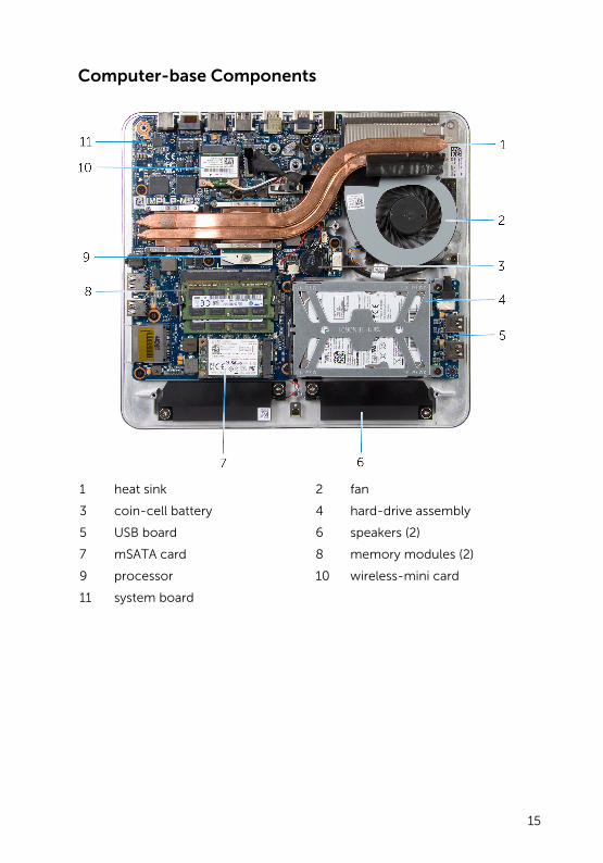
Computer-base Components
1 heat sink 2 fan
3 coin-cell battery 4 hard-drive assembly
5 USB board 6 speakers (2)
7 mSATA card 8 memory modules (2)
9 processor 10 wireless-mini card
11 system board
15
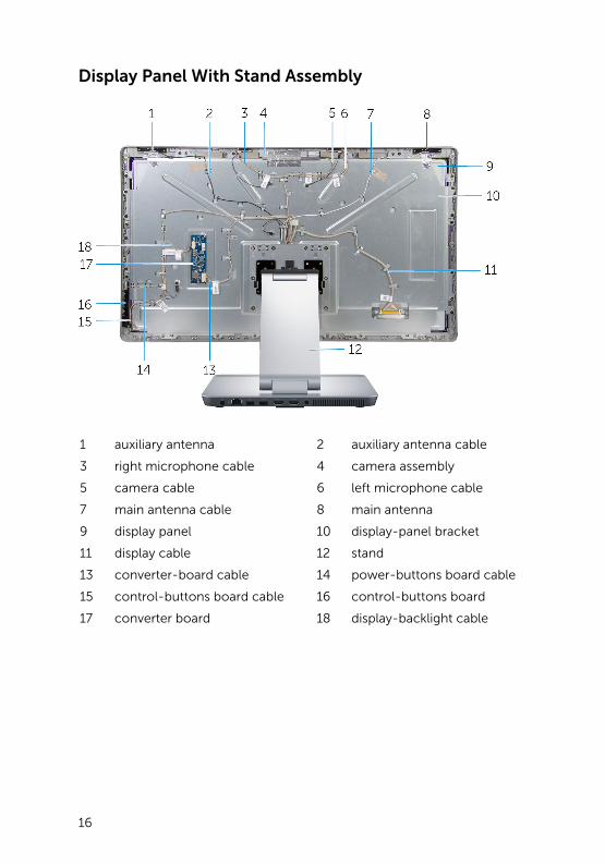
Display Panel With Stand Assembly
1 auxiliary antenna 2 auxiliary antenna cable
3 right microphone cable 4 camera assembly
5 camera cable 6 left microphone cable
7 main antenna cable 8 main antenna
9 display panel 10 display-panel bracket
11 display cable 12 stand
13 converter-board cable 14 power-buttons board cable
15 control-buttons board cable 16 control-buttons board
17 converter board 18 display-backlight cable
16
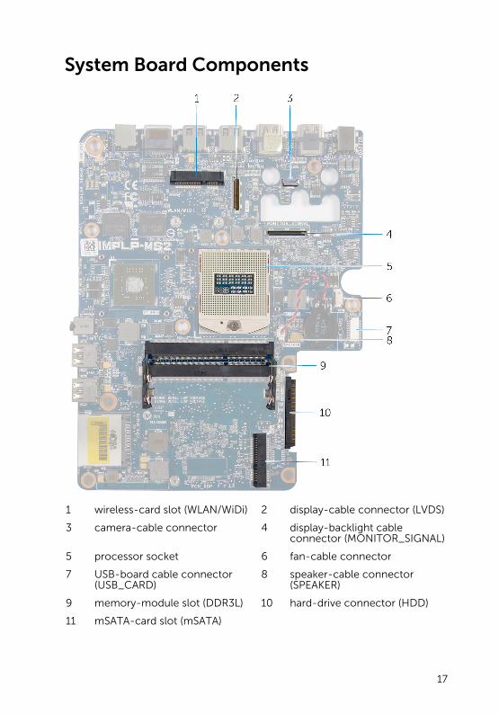
System Board Components
1 wireless-card slot (WLAN/WiDi) 2 display-cable connector (LVDS)
3 camera-cable connector 4 display-backlight cable connector (MONITOR_SIGNAL)
5 processor socket 6 fan-cable connector
7 USB-board cable connector (USB_CARD)
8 speaker-cable connector (SPEAKER)
9 memory-module slot (DDR3L) 10 hard-drive connector (HDD)
11 mSATA-card slot (mSATA)
17
Removing the Memory Module(s)
WARNING: Before working inside your computer, read the safety information that shipped with your computer and follow the steps in Before Working Inside Your Computer. After working inside your computer, follow the instructions in After Working Inside Your Computer. For more safety best practices, see the Regulatory Compliance home page at dell.com/regulatory_compliance.
Procedure
1 Loosen the captive screw that secures the memory-module cover to the base cover.
18
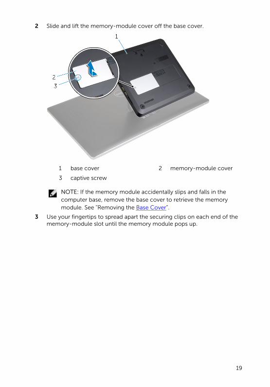
2 Slide and lift the memory-module cover off the base cover.
1 base cover 2 memory-module cover
3 captive screw
NOTE: If the memory module accidentally slips and falls in the computer base, remove the base cover to retrieve the memory module. See "Removing the Base Cover”.
3 Use your fingertips to spread apart the securing clips on each end of the memory-module slot until the memory module pops up.
19
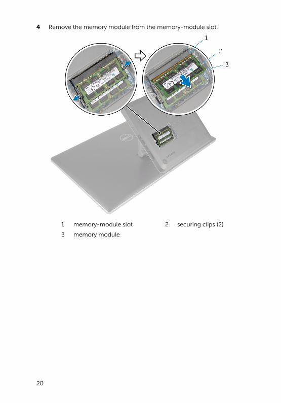
4 Remove the memory module from the memory-module slot.
1 memory-module slot 2 securing clips (2)
3 memory module
20
Replacing the Memory Module(s)
WARNING: Before working inside your computer, read the safety information that shipped with your computer and follow the steps in Before Working Inside Your Computer. After working inside your computer, follow the instructions in After Working Inside Your Computer. For more safety best practices, see the Regulatory Compliance home page at dell.com/regulatory_compliance.
Procedure
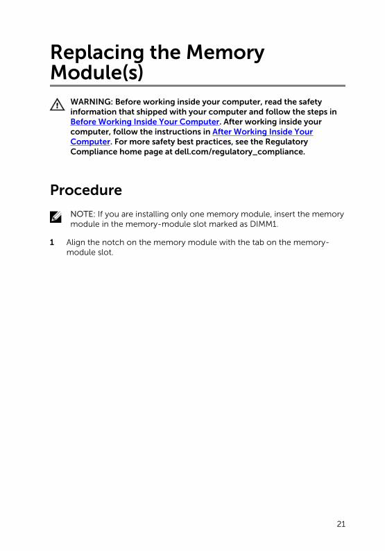
NOTE: If you are installing only one memory module, insert the memory module in the memory-module slot marked as DIMM1.
1 Align the notch on the memory module with the tab on the memory-module slot.
21
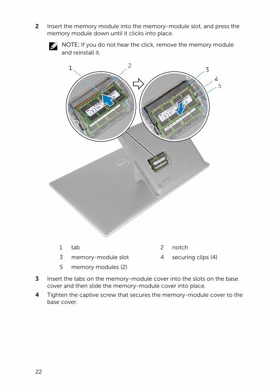
2 Insert the memory module into the memory-module slot, and press the memory module down until it clicks into place.
NOTE: If you do not hear the click, remove the memory module and reinstall it.
1 tab 2 notch
3 memory-module slot 4 securing clips (4)
5 memory modules (2)
3 Insert the tabs on the memory-module cover into the slots on the base cover and then slide the memory-module cover into place.
4 Tighten the captive screw that secures the memory-module cover to the base cover.
22
Removing the Base CoverWARNING: Before working inside your computer, read the safety information that shipped with your computer and follow the steps in Before Working Inside Your Computer. After working inside your computer, follow the instructions in After Working Inside Your Computer. For more safety best practices, see the Regulatory Compliance home page at dell.com/regulatory_compliance.
Procedure
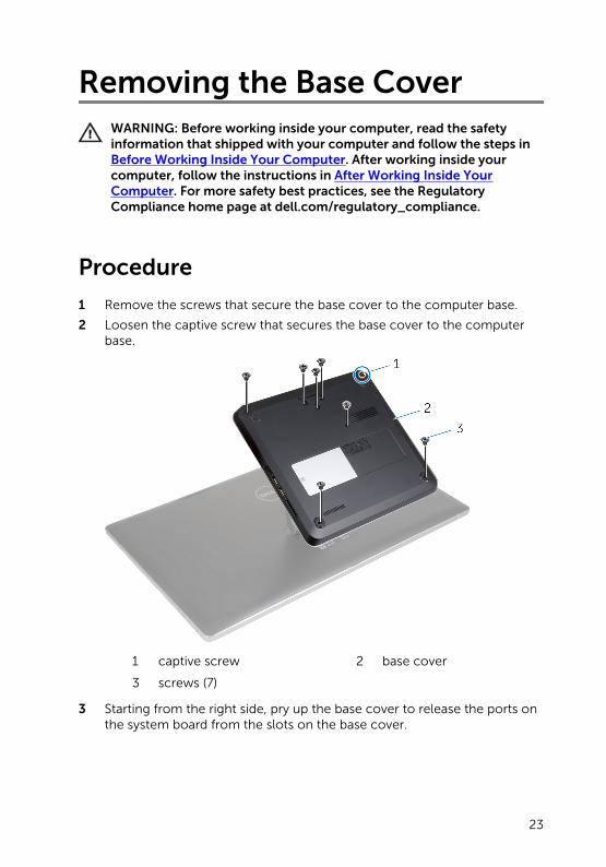
1 Remove the screws that secure the base cover to the computer base.
2 Loosen the captive screw that secures the base cover to the computer base.
1 captive screw 2 base cover
3 screws (7)
3 Starting from the right side, pry up the base cover to release the ports on the system board from the slots on the base cover.
23
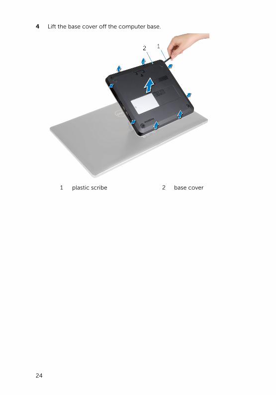
4 Lift the base cover off the computer base.
1 plastic scribe 2 base cover
24
Replacing the Base CoverWARNING: Before working inside your computer, read the safety information that shipped with your computer and follow the steps in Before Working Inside Your Computer. After working inside your computer, follow the instructions in After Working Inside Your Computer. For more safety best practices, see the Regulatory Compliance home page at dell.com/regulatory_compliance.
Procedure
1 Slide the slots on the base cover into the ports on the system board and snap the base cover into place.
2 Replace the screws that secure the base cover to the computer base.
3 Tighten the captive screw that secures the base cover to the computer base.
25
Removing the Computer BaseWARNING: Before working inside your computer, read the safety information that shipped with your computer and follow the steps in Before Working Inside Your Computer. After working inside your computer, follow the instructions in After Working Inside Your Computer. For more safety best practices, see the Regulatory Compliance home page at dell.com/regulatory_compliance.
Prerequisites
Remove the base cover.
Procedure
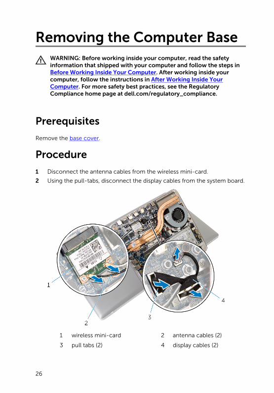
1 Disconnect the antenna cables from the wireless mini-card.
2 Using the pull-tabs, disconnect the display cables from the system board.
1 wireless mini-card 2 antenna cables (2)
3 pull tabs (2) 4 display cables (2)
26
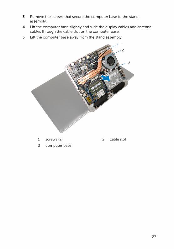
3 Remove the screws that secure the computer base to the stand assembly.
4 Lift the computer base slightly and slide the display cables and antenna cables through the cable slot on the computer base.
5 Lift the computer base away from the stand assembly.
1 screws (2) 2 cable slot
3 computer base
27
Replacing the Computer BaseWARNING: Before working inside your computer, read the safety information that shipped with your computer and follow the steps in Before Working Inside Your Computer. After working inside your computer, follow the instructions in After Working Inside Your Computer. For more safety best practices, see the Regulatory Compliance home page at dell.com/regulatory_compliance.
Procedure
1 Slide the display cables and antenna cables through the cable slot on the computer base.
2 Place the computer base on the stand assembly and align the screw holes on the computer base with the screw holes on the stand assembly.
3 Replace the screws that secure the computer base to the stand assembly.
4 Connect the display cables to the system board.
5 Connect the antenna cables to the wireless mini-card.
Post-requisites
Replace the base cover.
28
Removing the Hard DriveWARNING: Before working inside your computer, read the safety information that shipped with your computer and follow the steps in Before Working Inside Your Computer. After working inside your computer, follow the instructions in After Working Inside Your Computer. For more safety best practices, see the Regulatory Compliance home page at dell.com/regulatory_compliance.
CAUTION: Hard drives are fragile. Exercise care when handling the hard drive.
CAUTION: To avoid data loss, do not remove the hard drive while the computer is in sleep or on state.
Prerequisites
1 Remove the base cover.
2 Remove the computer base.
Procedure
1 Disconnect the speaker cable from the system board.
2 Note the speaker-cable routing and remove the cable from the routing guides on the hard-drive assembly.
3 Remove the screws that secure the hard-drive assembly to the computer base.
29
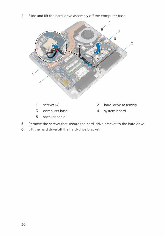
4 Slide and lift the hard-drive assembly off the computer base.
1 screws (4) 2 hard-drive assembly
3 computer base 4 system board
5 speaker cable
5 Remove the screws that secure the hard-drive bracket to the hard drive.
6 Lift the hard drive off the hard-drive bracket.
30
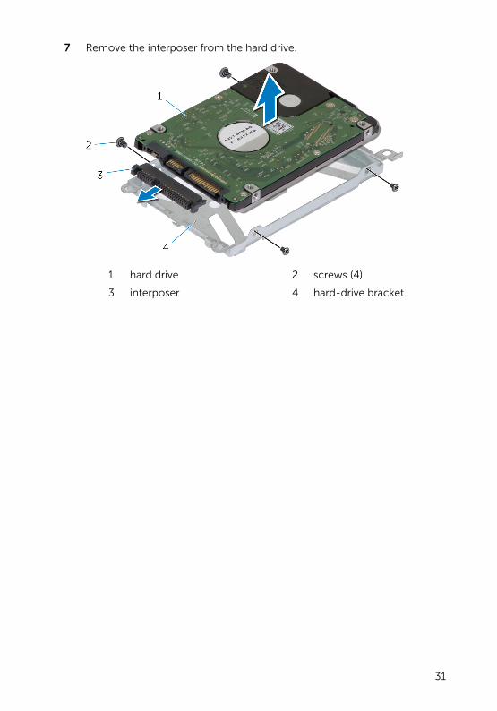
7 Remove the interposer from the hard drive.
1 hard drive 2 screws (4)
3 interposer 4 hard-drive bracket
31
Replacing the Hard DriveWARNING: Before working inside your computer, read the safety information that shipped with your computer and follow the steps in Before Working Inside Your Computer. After working inside your computer, follow the instructions in After Working Inside Your Computer. For more safety best practices, see the Regulatory Compliance home page at dell.com/regulatory_compliance.
CAUTION: Hard drives are fragile. Exercise care when handling the hard drive.
Procedure
1 Connect the interposer to the connector on the hard drive.
2 Place the hard drive in the hard-drive bracket.
3 Align the screw holes on the hard-drive bracket with the screw holes on the hard-drive assembly.
4 Replace the screws that secure the hard-drive bracket to the hard-drive assembly.
5 Place the hard-drive assembly on the computer base and slide the hard-drive assembly into place.
6 Replace the screws that secure the hard-drive assembly to the computer base.
7 Route the speaker cable through the routing guides on the hard-drive assembly.
8 Connect the speaker cable to the system board.
Post-requisites
1 Replace the computer base.
2 Replace the base cover.
32
Removing the Wireless CardWARNING: Before working inside your computer, read the safety information that shipped with your computer and follow the steps in Before Working Inside Your Computer. After working inside your computer, follow the instructions in After Working Inside Your Computer. For more safety best practices, see the Regulatory Compliance home page at dell.com/regulatory_compliance.
Prerequisites
1 Remove the base cover.
2 Remove the computer base.
Procedure
1 Remove the screws that secure the wireless card to the system board.
33
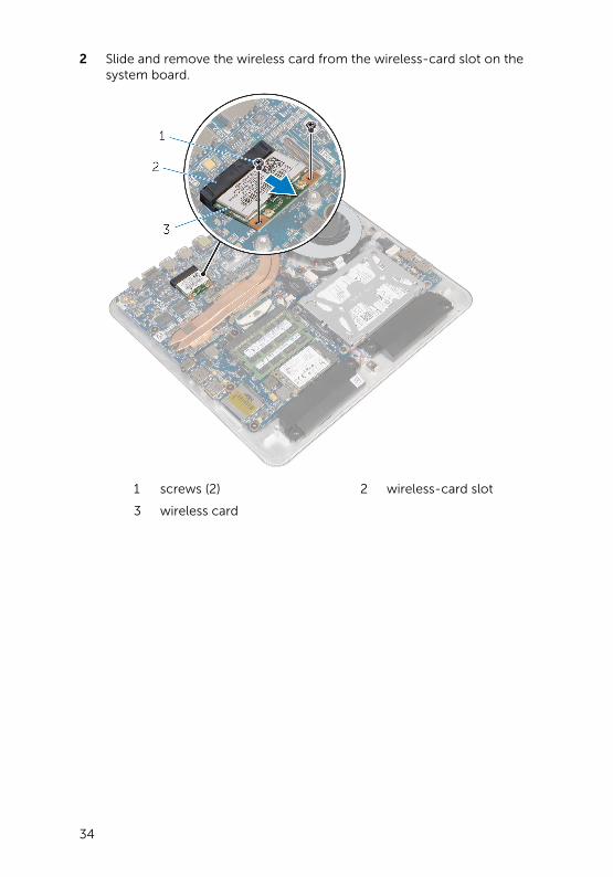
2 Slide and remove the wireless card from the wireless-card slot on the system board.
1 screws (2) 2 wireless-card slot
3 wireless card
34
Replacing the Wireless CardWARNING: Before working inside your computer, read the safety information that shipped with your computer and follow the steps in Before Working Inside Your Computer. After working inside your computer, follow the instructions in After Working Inside Your Computer. For more safety best practices, see the Regulatory Compliance home page at dell.com/regulatory_compliance.
Procedure
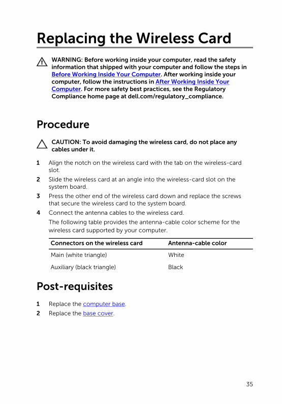
CAUTION: To avoid damaging the wireless card, do not place any cables under it.
1 Align the notch on the wireless card with the tab on the wireless-card slot.
2 Slide the wireless card at an angle into the wireless-card slot on the system board.
3 Press the other end of the wireless card down and replace the screws that secure the wireless card to the system board.
4 Connect the antenna cables to the wireless card.
The following table provides the antenna-cable color scheme for the wireless card supported by your computer.
Connectors on the wireless card Antenna-cable color
Main (white triangle) White
Auxiliary (black triangle) Black
Post-requisites
1 Replace the computer base.
2 Replace the base cover.
35
Removing the mSATA CardWARNING: Before working inside your computer, read the safety information that shipped with your computer and follow the steps in Before Working Inside Your Computer. After working inside your computer, follow the instructions in After Working Inside Your Computer. For more safety best practices, see the Regulatory Compliance home page at dell.com/regulatory_compliance.
Prerequisites
1 Remove the base cover.
2 Remove the computer base.
Procedure
1 Remove the screw that secures the mSATA card to the system board.
36
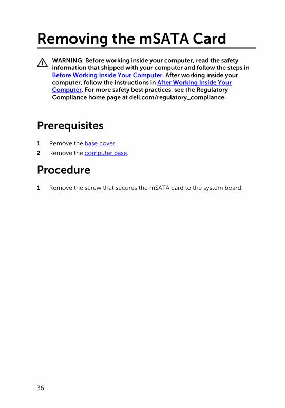
2 Slide and remove the mSATA card from the mSATA-card slot on the system board.
1 mSATA-card slot 2 mSATA card
3 screw 4 system board
37
Replacing the mSATA CardWARNING: Before working inside your computer, read the safety information that shipped with your computer and follow the steps in Before Working Inside Your Computer. After working inside your computer, follow the instructions in After Working Inside Your Computer. For more safety best practices, see the Regulatory Compliance home page at dell.com/regulatory_compliance.
Procedure
1 Align the notch on the mSATA card with the tab on the mSATA-card slot.
2 Slide the mSATA card at an angle into the mSATA-card slot.
38
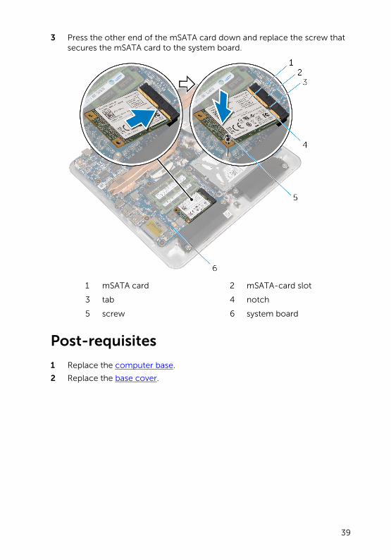
3 Press the other end of the mSATA card down and replace the screw that secures the mSATA card to the system board.
1 mSATA card 2 mSATA-card slot
3 tab 4 notch
5 screw 6 system board
Post-requisites
1 Replace the computer base.
2 Replace the base cover.
39
Removing the SpeakersWARNING: Before working inside your computer, read the safety information that shipped with your computer and follow the steps in Before Working Inside Your Computer. After working inside your computer, follow the instructions in After Working Inside Your Computer. For more safety best practices, see the Regulatory Compliance home page at dell.com/regulatory_compliance.
Prerequisites
1 Remove the base cover.
2 Remove the computer base.
Procedure
1 Disconnect the speaker cable from the system board.
2 Note the speaker cable routing and remove the cable from the routing guides.
3 Remove the screws that secure the speakers to the computer base.
40
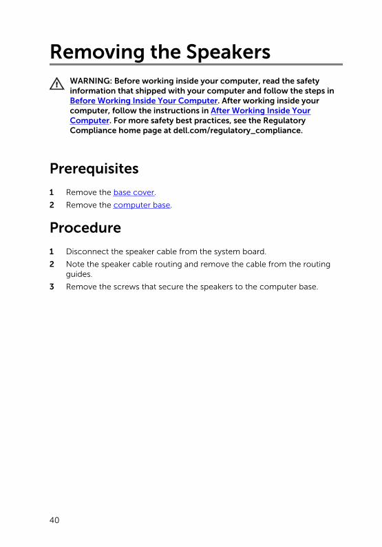
4 Lift the speakers along with the cable off the computer base.
1 speaker cable 2 screws (4)
3 speakers (2) 4 computer base
41
Replacing the SpeakersWARNING: Before working inside your computer, read the safety information that shipped with your computer and follow the steps in Before Working Inside Your Computer. After working inside your computer, follow the instructions in After Working Inside Your Computer. For more safety best practices, see the Regulatory Compliance home page at dell.com/regulatory_compliance.
Procedure
1 Align the screw holes on the speakers with the screw holes on the computer base.
2 Replace the screws that secure the speakers to the computer base.
3 Route the speaker cable through the routing guides.
4 Connect the speaker cable to the system board.
Post-requisites
1 Replace the computer base.
2 Replace the base cover.
42
Removing the USB BoardWARNING: Before working inside your computer, read the safety information that shipped with your computer and follow the steps in Before Working Inside Your Computer. After working inside your computer, follow the instructions in After Working Inside Your Computer. For more safety best practices, see the Regulatory Compliance home page at dell.com/regulatory_compliance.
Prerequisites
1 Remove the base cover.
2 Remove the computer base.
3 Follow the procedure from step 1 to step 4 in “Removing the Hard Drive”.
Procedure
1 Peel off the tape from the USB-board cable.
2 Open the clip of the USB-board cable routing.
3 Using the pull tab, disconnect the USB-board cable from the USB board and remove it from the cable-routing clip.
4 Remove the screw that secures the USB board to the computer base.
43
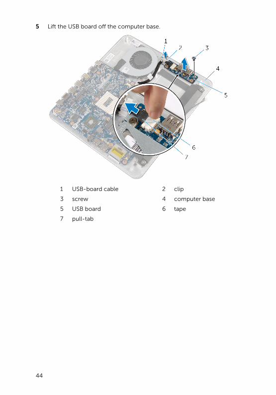
5 Lift the USB board off the computer base.
1 USB-board cable 2 clip
3 screw 4 computer base
5 USB board 6 tape
7 pull-tab
44
Replacing the USB BoardWARNING: Before working inside your computer, read the safety information that shipped with your computer and follow the steps in Before Working Inside Your Computer. After working inside your computer, follow the instructions in After Working Inside Your Computer. For more safety best practices, see the Regulatory Compliance home page at dell.com/regulatory_compliance.
Procedure
1 Align the screw hole on the USB board with the screw hole on the computer base.
2 Replace the screw that secures the USB board to the computer base.
3 Route the USB-board cable through the routing clip on the computer base and close the routing clip.
4 Connect the USB-board cable to the connector on the USB board.
5 Adhere the USB-board cable to the USB board.
Post-requisites
1 Follow the procedure from step 5 to step 8 in “Replacing the Hard Drive”.
2 Replace the computer base.
3 Replace the base cover.
45
Removing the Coin-Cell Battery
WARNING: Before working inside your computer, read the safety information that shipped with your computer and follow the steps in Before Working Inside Your Computer. After working inside your computer, follow the instructions in After Working Inside Your Computer. For more safety best practices, see the Regulatory Compliance home page at dell.com/regulatory_compliance.
CAUTION: Removing the coin-cell battery resets the BIOS settings to default. It is recommended that you note the BIOS settings before removing the coin-cell battery.
Prerequisites
1 Remove the base cover.
2 Remove the computer base.
Procedure
1 Disconnect the coin-cell battery cable from the system board.
2 Peel off the coin-cell battery from the system board.
46
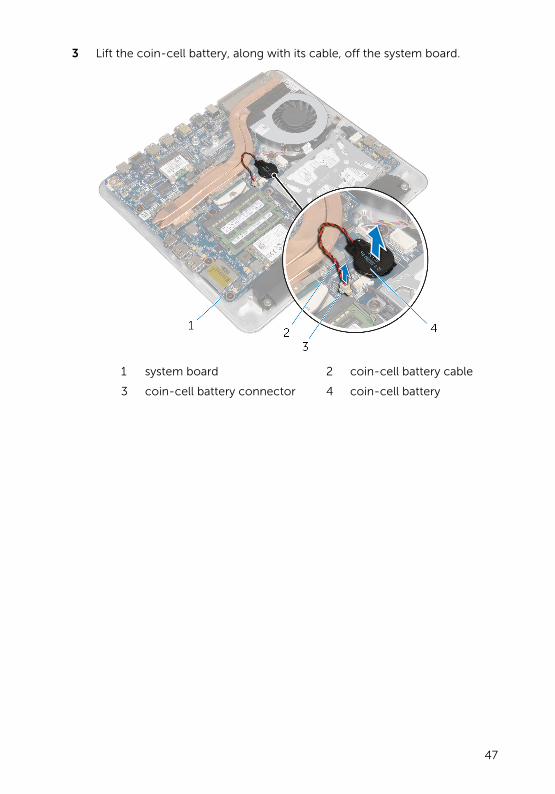
3 Lift the coin-cell battery, along with its cable, off the system board.
1 system board 2 coin-cell battery cable
3 coin-cell battery connector 4 coin-cell battery
47
Replacing the Coin-Cell Battery
WARNING: Before working inside your computer, read the safety information that shipped with your computer and follow the steps in Before Working Inside Your Computer. After working inside your computer, follow the instructions in After Working Inside Your Computer. For more safety best practices, see the Regulatory Compliance home page at dell.com/regulatory_compliance.
Procedure
1 Adhere the coin-cell battery to the system board.
2 Connect the coin-cell battery cable to the system board.
Post-requisites
1 Replace the computer base.
2 Replace the base cover.
48
Removing the FanWARNING: Before working inside your computer, read the safety information that shipped with your computer and follow the steps in Before Working Inside Your Computer. After working inside your computer, follow the instructions in After Working Inside Your Computer. For more safety best practices, see the Regulatory Compliance home page at dell.com/regulatory_compliance.
Prerequisites
1 Remove the base cover.
2 Remove the computer base.
49
Procedure
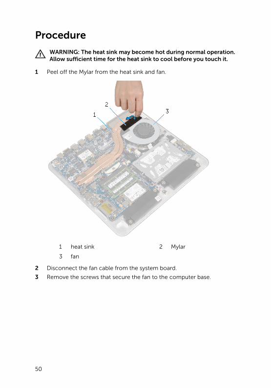
WARNING: The heat sink may become hot during normal operation. Allow sufficient time for the heat sink to cool before you touch it.
1 Peel off the Mylar from the heat sink and fan.
1 heat sink 2 Mylar
3 fan
2 Disconnect the fan cable from the system board.
3 Remove the screws that secure the fan to the computer base.
50
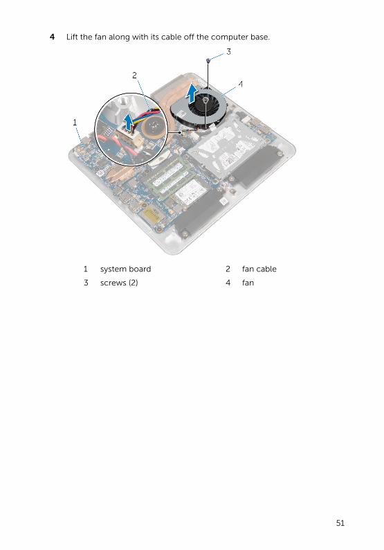
4 Lift the fan along with its cable off the computer base.
1 system board 2 fan cable
3 screws (2) 4 fan
51
Replacing the FanWARNING: Before working inside your computer, read the safety information that shipped with your computer and follow the steps in Before Working Inside Your Computer. After working inside your computer, follow the instructions in After Working Inside Your Computer. For more safety best practices, see the Regulatory Compliance home page at dell.com/regulatory_compliance.
Procedure
1 Align the screw holes on the fan with the screw holes on the computer base.
2 Replace the screws that secure the fan to the computer base.
3 Adhere the Mylar over the heat sink and fan.
4 Connect the fan cable to the system board.
Post-requisites
1 Replace the computer base.
2 Replace the base cover.
52
Removing the Heat SinkWARNING: Before working inside your computer, read the safety information that shipped with your computer and follow the steps in Before Working Inside Your Computer. After working inside your computer, follow the instructions in After Working Inside Your Computer. For more safety best practices, see the Regulatory Compliance home page at dell.com/regulatory_compliance.
WARNING: The heat sink may become hot during normal operation. Allow sufficient time for the heat sink to cool before you touch it.
CAUTION: For maximum cooling of the processor, do not touch the heat transfer areas on the heat sink. The oils in your skin can reduce the heat transfer capability of the thermal grease.
Prerequisites
NOTE: The heat sink may look different on your computer depending on the configuration you ordered.
1 Remove the base cover.
2 Remove the computer base.
53
Procedure
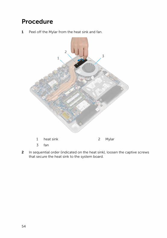
1 Peel off the Mylar from the heat sink and fan.
1 heat sink 2 Mylar
3 fan
2 In sequential order (indicated on the heat sink), loosen the captive screws that secure the heat sink to the system board.
54
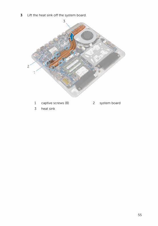
3 Lift the heat sink off the system board.
1 captive screws (8) 2 system board
3 heat sink
55
Replacing the Heat SinkWARNING: Before working inside your computer, read the safety information that shipped with your computer and follow the steps in Before Working Inside Your Computer. After working inside your computer, follow the instructions in After Working Inside Your Computer. For more safety best practices, see the Regulatory Compliance home page at dell.com/regulatory_compliance.
CAUTION: Incorrect alignment of the heat sink can cause damage to the system board and processor.
NOTE: The original thermal grease can be reused if the original system board and heat sink are reinstalled together. If either the system board or the heat sink is replaced, use the thermal pad provided in the kit to make sure that thermal conductivity is achieved.
Procedure
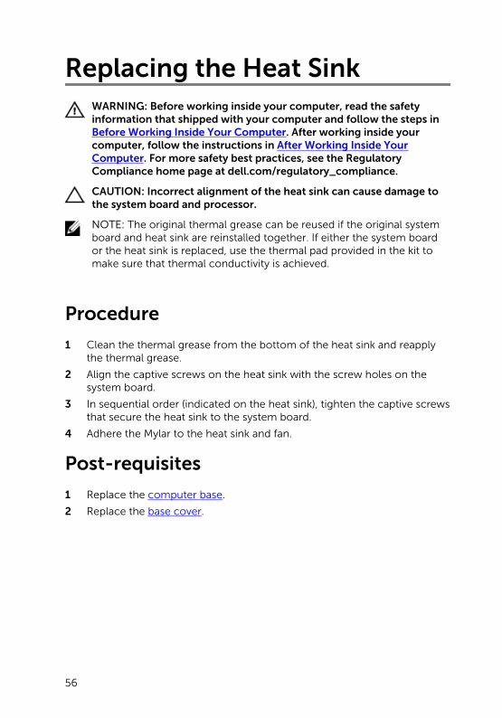
1 Clean the thermal grease from the bottom of the heat sink and reapply the thermal grease.
2 Align the captive screws on the heat sink with the screw holes on the system board.
3 In sequential order (indicated on the heat sink), tighten the captive screws that secure the heat sink to the system board.
4 Adhere the Mylar to the heat sink and fan.
Post-requisites
1 Replace the computer base.
2 Replace the base cover.
56
Removing the ProcessorWARNING: Before working inside your computer, read the safety information that shipped with your computer and follow the steps in Before Working Inside Your Computer. After working inside your computer, follow the instructions in After Working Inside Your Computer. For more safety best practices, see the Regulatory Compliance home page at dell.com/regulatory_compliance.
Prerequisites
1 Remove the base cover
2 Remove the computer base.
3 Remove the heat sink.
Procedure
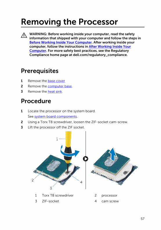
1 Locate the processor on the system board.
See system board components.
2 Using a Torx T8 screwdriver, loosen the ZIF-socket cam-screw.
3 Lift the processor off the ZIF socket.
1 Torx T8 screwdriver 2 processor
3 ZIF-socket 4 cam screw
57
Replacing the ProcessorWARNING: Before working inside your computer, read the safety information that shipped with your computer and follow the steps in Before Working Inside Your Computer. After working inside your computer, follow the instructions in After Working Inside Your Computer. For more safety best practices, see the Regulatory Compliance home page at dell.com/regulatory_compliance.
CAUTION: If either the processor or the heat sink is replaced, use the thermal grease provided in the kit to make sure that thermal conductivity is achieved.
Procedure
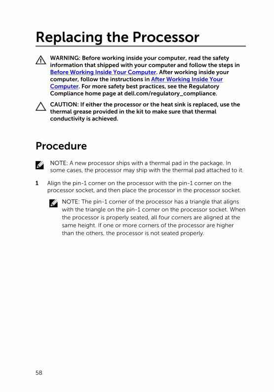
NOTE: A new processor ships with a thermal pad in the package. In some cases, the processor may ship with the thermal pad attached to it.
1 Align the pin-1 corner on the processor with the pin-1 corner on the processor socket, and then place the processor in the processor socket.
NOTE: The pin-1 corner of the processor has a triangle that aligns with the triangle on the pin-1 corner on the processor socket. When the processor is properly seated, all four corners are aligned at the same height. If one or more corners of the processor are higher than the others, the processor is not seated properly.
58
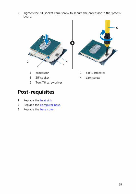
2 Tighten the ZIF socket cam-screw to secure the processor to the system board.
1 processor 2 pin-1 indicator
3 ZIF socket 4 cam screw
5 Torx T8 screwdriver
Post-requisites
1 Replace the heat sink.
2 Replace the computer base.
3 Replace the base cover.
59
Removing the System BoardWARNING: Before working inside your computer, read the safety information that shipped with your computer and follow the steps in Before Working Inside Your Computer. After working inside your computer, follow the instructions in After Working Inside Your Computer. For more safety best practices, see the Regulatory Compliance home page at dell.com/regulatory_compliance.
NOTE: Your computer’s Service Tag is stored in the system board. You must enter the Service Tag in the BIOS setup program after you replace the system board.
NOTE: Replacing the system board removes any changes you have made to the BIOS using the BIOS setup program. You must make the desired changes again after you replace the system board.
NOTE: Before disconnecting the cables from the system board, note the location of the connectors so that you can reconnect them correctly after you replace the system board.
Prerequisites
1 Remove the base cover.
2 Remove the computer base.
3 Remove the memory module(s).
4 Follow the procedure from step 1 to step 4 in “Removing the Hard Drive”.
5 Remove the mSATA card.
6 Remove the wireless card.
7 Remove the coin-cell battery.
8 Remove the heat sink.
9 Remove the processor.
Procedure
1 Disconnect the fan cable from the system board.
2 Peel off the tape from the USB-board cable.
3 Using the pull tab, disconnect the USB-board cable from the system board.
60
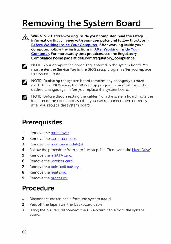
4 Remove the screws that secure the system board to the computer base.
5 Lift the system board out of the computer base.
1 USB-board cable 2 tape
3 fan cable 4 screws (7)
5 system board
61
Replacing the System BoardWARNING: Before working inside your computer, read the safety information that shipped with your computer and follow the steps in Before Working Inside Your Computer. After working inside your computer, follow the instructions in After Working Inside Your Computer. For more safety best practices, see the Regulatory Compliance home page at dell.com/regulatory_compliance.
NOTE: Your computer’s Service Tag is stored in the system board. You must enter the Service Tag in the BIOS setup program after you replace the system board.
NOTE: Replacing the system board removes any changes you have made to the BIOS using the BIOS setup program. You must make the desired changes again after you replace the system board.
Procedure
1 Align the screw holes on the system board with the screw holes on the computer base.
2 Replace the screws that secure the system board to the computer base.
3 Connect the USB-board cable to the system board.
4 Adhere the USB-board cable to the USB board.
5 Connect the fan cable to the system board.
Post-requisites
1 Replace the processor.
2 Replace the heat sink.
3 Replace the coin-cell battery.
4 Replace the wireless card.
5 Replace the mSATA card.
6 Follow the procedure from step 5 to step 8 in “Replacing the Hard Drive”.
7 Replace the memory module(s).
8 Replace the computer base.
9 Replace the base cover.
62
Removing the Back CoverWARNING: Before working inside your computer, read the safety information that shipped with your computer and follow the steps in Before Working Inside Your Computer. After working inside your computer, follow the instructions in After Working Inside Your Computer. For more safety best practices, see the Regulatory Compliance home page at dell.com/regulatory_compliance.
Prerequisites
1 Remove the base cover.
2 Remove the computer base.
Procedure
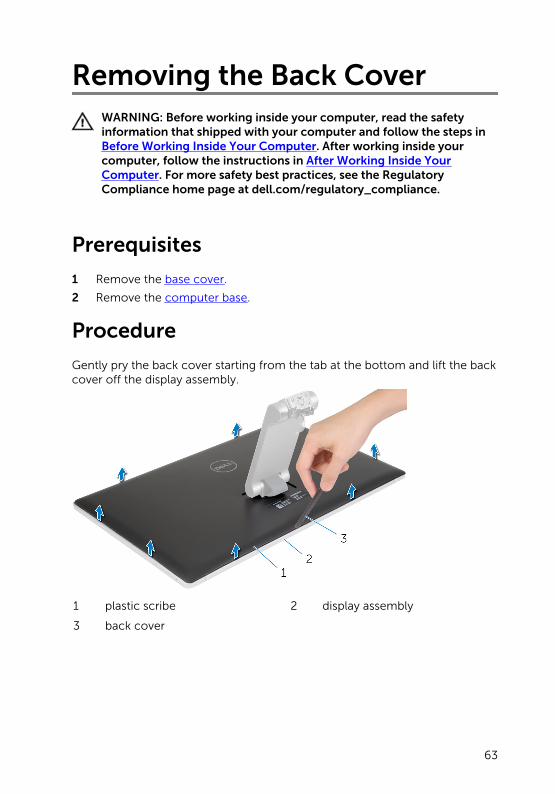
Gently pry the back cover starting from the tab at the bottom and lift the back cover off the display assembly.
1 plastic scribe 2 display assembly
3 back cover
63
Replacing the Back CoverWARNING: Before working inside your computer, read the safety information that shipped with your computer and follow the steps in Before Working Inside Your Computer. After working inside your computer, follow the instructions in After Working Inside Your Computer. For more safety best practices, see the Regulatory Compliance home page at dell.com/regulatory_compliance.
Procedure
Align the tabs on the back cover with the tabs on the display bezel and snap the back cover into place.
Post-requisites
1 Replace the computer base.
2 Replace the base cover.
64
Removing the CameraWARNING: Before working inside your computer, read the safety information that shipped with your computer and follow the steps in Before Working Inside Your Computer. After working inside your computer, follow the instructions in After Working Inside Your Computer. For more safety best practices, see the Regulatory Compliance home page at dell.com/regulatory_compliance.
Prerequisites
1 Remove the base cover.
2 Remove the computer base.
3 Remove the back cover.
Procedure
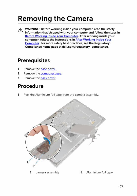
1 Peel the Aluminium foil tape from the camera assembly.
1 camera assembly 2 Aluminium foil tape
65
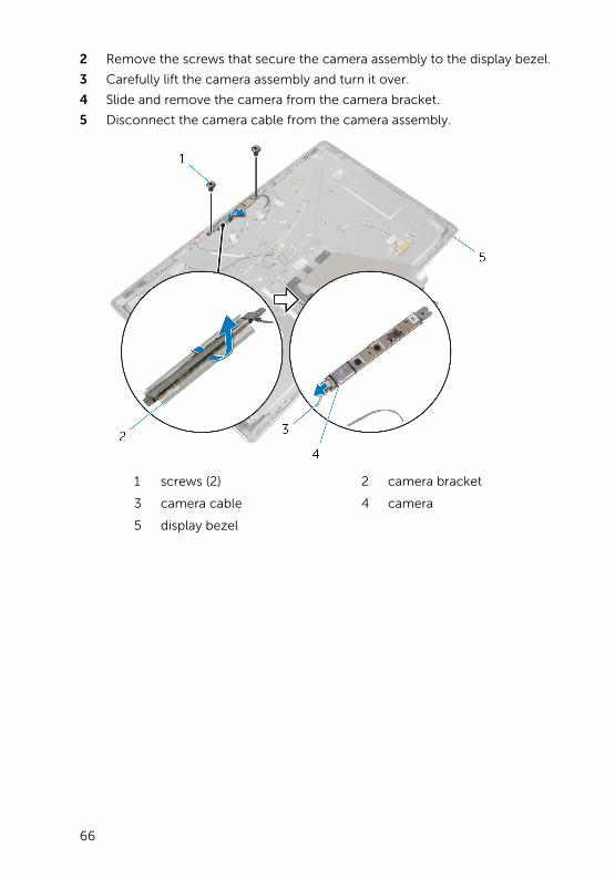
2 Remove the screws that secure the camera assembly to the display bezel.
3 Carefully lift the camera assembly and turn it over.
4 Slide and remove the camera from the camera bracket.
5 Disconnect the camera cable from the camera assembly.
1 screws (2) 2 camera bracket
3 camera cable 4 camera
5 display bezel
66
Replacing the CameraWARNING: Before working inside your computer, read the safety information that shipped with your computer and follow the steps in Before Working Inside Your Computer. After working inside your computer, follow the instructions in After Working Inside Your Computer. For more safety best practices, see the Regulatory Compliance home page at dell.com/regulatory_compliance.
Procedure
1 Slide the camera into the camera bracket.
2 Connect the camera cable to the camera.
3 Align the screw holes on the camera assembly with the screw holes on the display bezel.
4 Replace the screws that secure the camera assembly to the display bezel.
5 Adhere the Aluminium foil tape that secures the camera assembly to the display bezel.
Post-requisites
1 Replace the back cover.
2 Replace the computer base.
3 Replace the base cover.
67
Removing the MicrophoneWARNING: Before working inside your computer, read the safety information that shipped with your computer and follow the steps in Before Working Inside Your Computer. After working inside your computer, follow the instructions in After Working Inside Your Computer. For more safety best practices, see the Regulatory Compliance home page at dell.com/regulatory_compliance.
Prerequisites
1 Remove the base cover.
2 Remove the computer base.
3 Remove the back cover.
Procedure
1 Carefully pry and lift the microphones out of their slots on the display bezel.
68
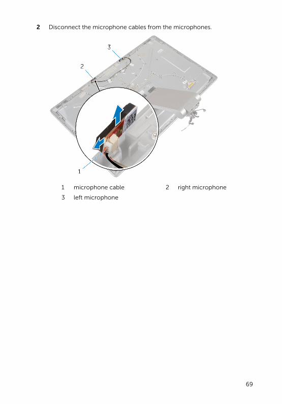
2 Disconnect the microphone cables from the microphones.
1 microphone cable 2 right microphone
3 left microphone
69
Replacing the MicrophoneWARNING: Before working inside your computer, read the safety information that shipped with your computer and follow the steps in Before Working Inside Your Computer. After working inside your computer, follow the instructions in After Working Inside Your Computer. For more safety best practices, see the Regulatory Compliance home page at dell.com/regulatory_compliance.
Procedure
1 Connect the microphone cable to the microphones.
2 Align the microphones with the slots on the display bezel and slide the microphones into the slots on the display bezel.
Post-requisites
1 Replace the back cover.
2 Replace the computer base.
3 Replace the base cover.
70
Removing the Converter Board
WARNING: Before working inside your computer, read the safety information that shipped with your computer and follow the steps in Before Working Inside Your Computer. After working inside your computer, follow the instructions in After Working Inside Your Computer. For more safety best practices, see the Regulatory Compliance home page at dell.com/regulatory_compliance.
Prerequisites
1 Remove the base cover.
2 Remove the computer base.
3 Remove the back cover.
Procedure
1 Disconnect the converter-board cable from the converter board.
2 Disconnect the display-backlight cable from the converter board.
3 Remove the screws that secure the converter board to the display bracket.
71
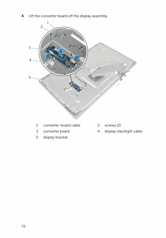
4 Lift the converter board off the display assembly.
1 converter-board cable 2 screws (2)
3 converter board 4 display-backlight cable
5 display bracket
72
Replacing the Converter BoardWARNING: Before working inside your computer, read the safety information that shipped with your computer and follow the steps in Before Working Inside Your Computer. After working inside your computer, follow the instructions in After Working Inside Your Computer. For more safety best practices, see the Regulatory Compliance home page at dell.com/regulatory_compliance.
Procedure
1 Align the screw holes on the converter board with the screw holes on the display bracket.
2 Replace the screws that secure the converter board to the display bracket.
3 Connect the converter-board cable to the converter board.
4 Connect the display-backlight cable to the converter board.
Post-requisites
1 Replace the back cover.
2 Replace the computer base.
3 Replace the base cover.
73
Removing the Power-Button Module
WARNING: Before working inside your computer, read the safety information that shipped with your computer and follow the steps in Before Working Inside Your Computer. After working inside your computer, follow the instructions in After Working Inside Your Computer. For more safety best practices, see the Regulatory Compliance home page at dell.com/regulatory_compliance.
Prerequisites
1 Remove the base cover.
2 Remove the computer base.
3 Remove the back cover.
Procedure
NOTE: Note the routing of the cable as you remove it so that you can reroute it correctly after you replace the power-button module.
1 Note the power-button cable routing and remove it from the routing guides.
2 Remove the screw that secures the power-button cable to the display bracket.
3 Disconnect the power-button cable from the control-buttons board cable.
4 Peel off the Mylar that covers the power button.
74
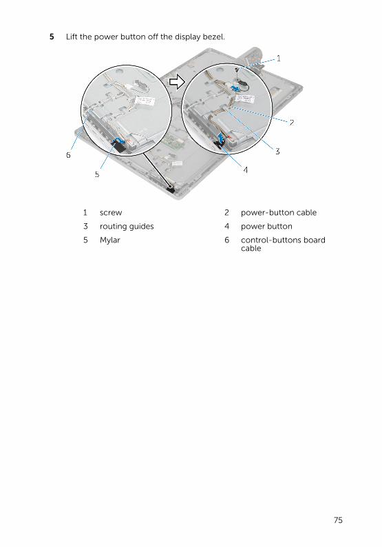
5 Lift the power button off the display bezel.
1 screw 2 power-button cable
3 routing guides 4 power button
5 Mylar 6 control-buttons board cable
75
Replacing the Power-Button Module
WARNING: Before working inside your computer, read the safety information that shipped with your computer and follow the steps in Before Working Inside Your Computer. After working inside your computer, follow the instructions in After Working Inside Your Computer. For more safety best practices, see the Regulatory Compliance home page at dell.com/regulatory_compliance.
Procedure
1 Place the power button in the display bezel and make sure that the power button fits in the slot on the display bezel.
2 Adhere the Mylar over the power button.
3 Route the power-button module cable through its routing guide.
4 Connect the power-button cable to the control-buttons board cable.
5 Replace the screw that secures the power-button cable to the display bracket.
Post-requisites
1 Replace the back cover.
2 Replace the computer base.
3 Replace the base cover.
76
Removing the Stand AssemblyWARNING: Before working inside your computer, read the safety information that shipped with your computer and follow the steps in Before Working Inside Your Computer. After working inside your computer, follow the instructions in After Working Inside Your Computer. For more safety best practices, see the Regulatory Compliance home page at dell.com/regulatory_compliance.
Prerequisites
1 Remove the base cover.
2 Remove the computer base.
3 Remove the back cover.
4 Remove the camera.
5 Remove the microphones.
Procedure
1 Disconnect the converter-board cable from the converter board.
2 Disconnect the display-backlight cable from the converter board.
3 Gently release the antennas from the alignment posts on the display bezel.
77
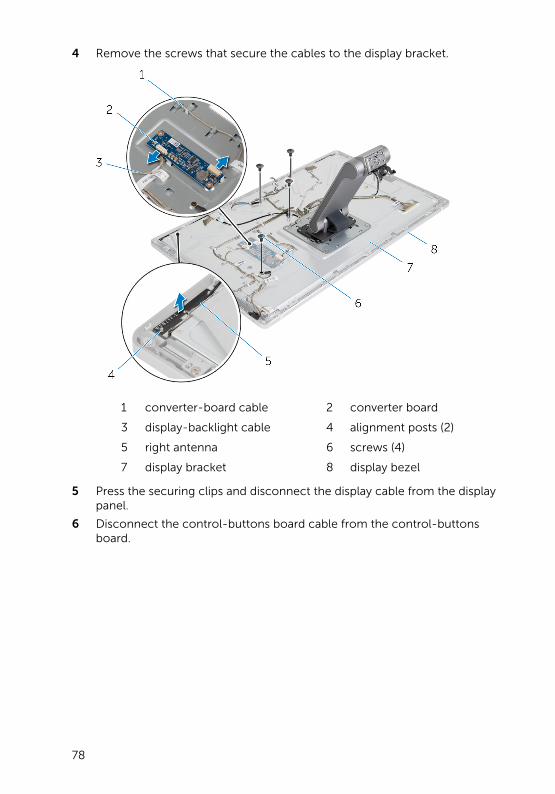
4 Remove the screws that secure the cables to the display bracket.
1 converter-board cable 2 converter board
3 display-backlight cable 4 alignment posts (2)
5 right antenna 6 screws (4)
7 display bracket 8 display bezel
5 Press the securing clips and disconnect the display cable from the display panel.
6 Disconnect the control-buttons board cable from the control-buttons board.
78
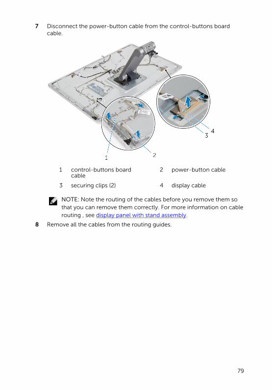
7 Disconnect the power-button cable from the control-buttons board cable.
1 control-buttons board cable
2 power-button cable
3 securing clips (2) 4 display cable
NOTE: Note the routing of the cables before you remove them so that you can remove them correctly. For more information on cable routing , see display panel with stand assembly.
8 Remove all the cables from the routing guides.
79
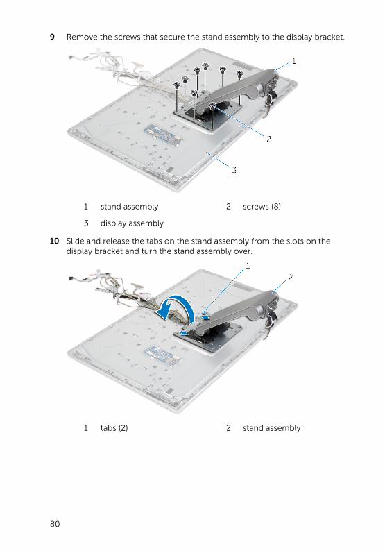
9 Remove the screws that secure the stand assembly to the display bracket.
1 stand assembly 2 screws (8)
3 display assembly
10 Slide and release the tabs on the stand assembly from the slots on the display bracket and turn the stand assembly over.
1 tabs (2) 2 stand assembly
80
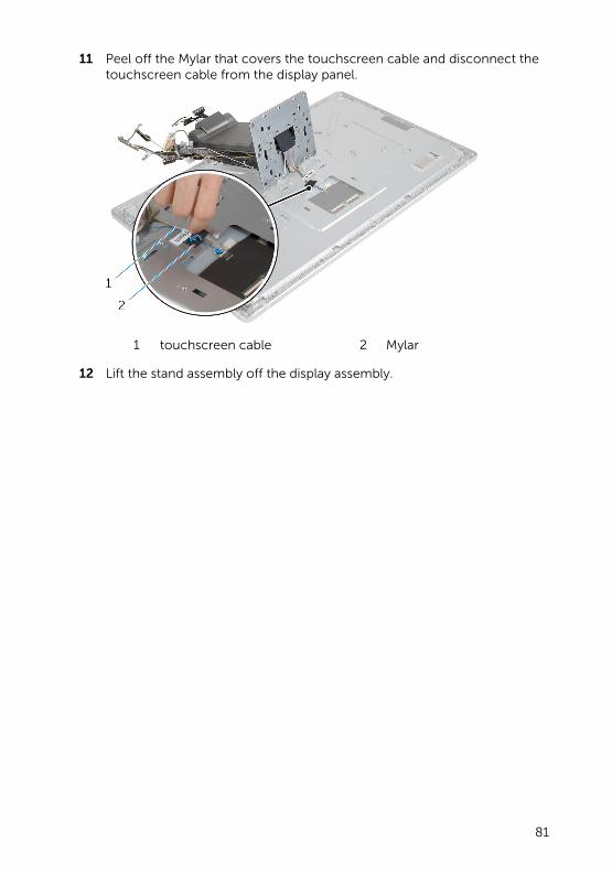
11 Peel off the Mylar that covers the touchscreen cable and disconnect the touchscreen cable from the display panel.
1 touchscreen cable 2 Mylar
12 Lift the stand assembly off the display assembly.
81
Replacing the Stand AssemblyWARNING: Before working inside your computer, read the safety information that shipped with your computer and follow the steps in Before Working Inside Your Computer. After working inside your computer, follow the instructions in After Working Inside Your Computer. For more safety best practices, see the Regulatory Compliance home page at dell.com/regulatory_compliance.
Procedure
1 Place the stand assembly on the display assembly.
2 Connect the touchscreen cable to the display panel and adhere the Mylar over the touchscreen cable.
3 Slide the tabs on the stand assembly into the slots on the display bracket.
4 Align the screw holes on the stand assembly with the screw holes on the display bracket.
5 Replace the screws that secure the stand assembly to the display bracket.
6 Route all the cables through their routing guides.
For more information, see display panel with stand assembly.
7 Replace the screws that secure the cables to the display bracket.
8 Connect the power-button cable to the control-buttons board cable.
9 Connect the control-buttons board cable to the control-buttons board.
10 Slide the display cable into the display-cable connector slot and connect the display cable to the display assembly.
11 Align the antenna modules with the alignment posts and adhere them to the display bezel.
12 Connect the converter-board cable and the display-backlight cable to the converter board.
Post-requisites
1 Replace the microphones.
2 Replace the camera.
3 Replace the back cover.
4 Replace the computer base.
82

5 Replace the base cover.
83
Removing the Display PanelWARNING: Before working inside your computer, read the safety information that shipped with your computer and follow the steps in Before Working Inside Your Computer. After working inside your computer, follow the instructions in After Working Inside Your Computer. For more safety best practices, see the Regulatory Compliance home page at dell.com/regulatory_compliance.
Prerequisites
1 Remove the base cover.
2 Remove the computer base.
3 Remove the back cover.
4 Remove the camera.
5 Remove the microphones.
6 Remove the stand assembly.
7 Remove the power button module.
Procedure
1 Remove the screws that secure the display-panel bracket to the display bezel.
84
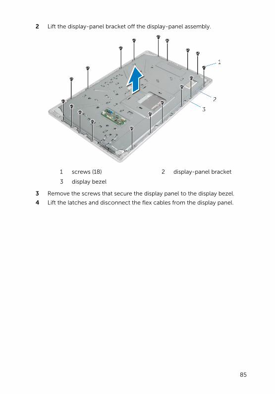
2 Lift the display-panel bracket off the display-panel assembly.
1 screws (18) 2 display-panel bracket
3 display bezel
3 Remove the screws that secure the display panel to the display bezel.
4 Lift the latches and disconnect the flex cables from the display panel.
85
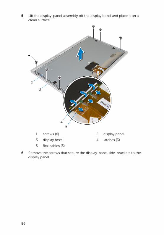
5 Lift the display-panel assembly off the display bezel and place it on a clean surface.
1 screws (6) 2 display panel
3 display bezel 4 latches (3)
5 flex cables (3)
6 Remove the screws that secure the display-panel side-brackets to the display panel.
86
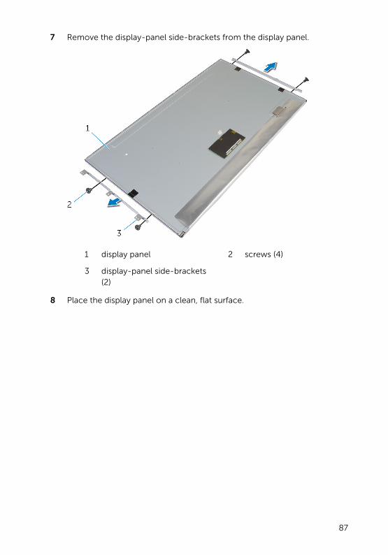
7 Remove the display-panel side-brackets from the display panel.
1 display panel 2 screws (4)
3 display-panel side-brackets (2)
8 Place the display panel on a clean, flat surface.
87
Replacing the Display PanelWARNING: Before working inside your computer, read the safety information that shipped with your computer and follow the steps in Before Working Inside Your Computer. After working inside your computer, follow the instructions in After Working Inside Your Computer. For more safety best practices, see the Regulatory Compliance home page at dell.com/regulatory_compliance.
Procedure
1 Place the display panel on a flat and clean surface.
2 Align the screw holes on the display-panel side-brackets with the screw holes on the display panel.
3 Replace the screws that secure display-panel side-brackets to the display panel.
4 Align the screw holes on the display-panel side-brackets with the screw holes on the display bezel and place the display panel to the display bezel.
NOTE: Make sure that no cables are under the display panel.
5 Slide the flex cables into the connectors on the display panel and press down on the connector latches to secure the cables.
6 Replace the screws that secure the display panel to the display bezel.
7 Replace the screws that secure the display-panel bracket to the display bezel.
Post-requisites
1 Replace the power-button module.
2 Replace the stand assembly.
3 Replace the microphones.
4 Replace the camera.
5 Replace the back cover.
6 Replace the computer base.
7 Replace the base cover.
88
Removing the Control-Buttons Board
WARNING: Before working inside your computer, read the safety information that shipped with your computer and follow the steps in Before Working Inside Your Computer. After working inside your computer, follow the instructions in After Working Inside Your Computer. For more safety best practices, see the Regulatory Compliance home page at dell.com/regulatory_compliance.
Prerequisites
1 Remove the base cover.
2 Remove the computer base.
3 Remove the back cover.
4 Remove the stand assembly.
5 Remove the camera.
6 Remove the microphones.
7 Remove the power-button module.
8 Remove the display panel.
Procedure
1 Pry the control-buttons bracket to release the control-buttons board from the tabs.
89
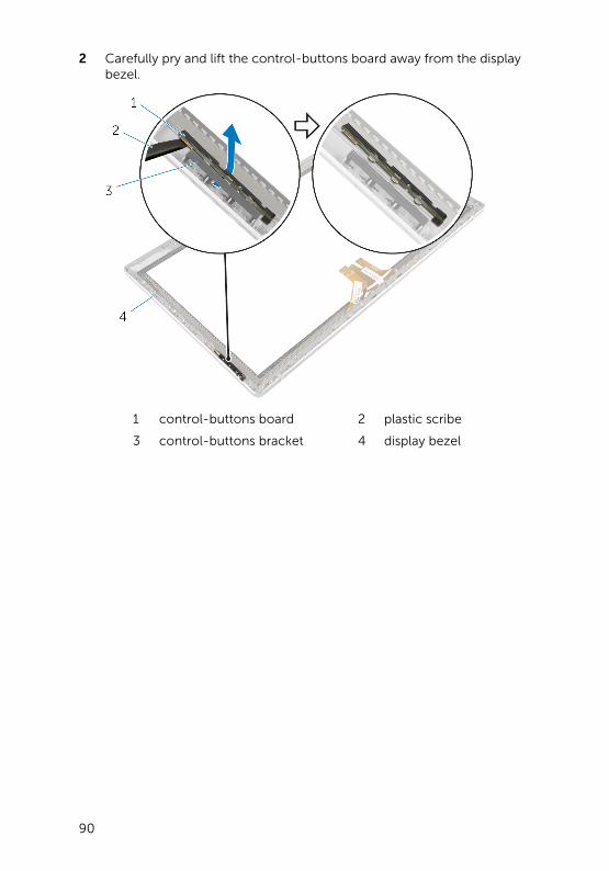
2 Carefully pry and lift the control-buttons board away from the display bezel.
1 control-buttons board 2 plastic scribe
3 control-buttons bracket 4 display bezel
90
Replacing the Control-Buttons Board
WARNING: Before working inside your computer, read the safety information that shipped with your computer and follow the steps in Before Working Inside Your Computer. After working inside your computer, follow the instructions in After Working Inside Your Computer. For more safety best practices, see the Regulatory Compliance home page at dell.com/regulatory_compliance.
Procedure
Place the control-buttons board into the control-buttons board bracket in such a way that the control-buttons board fits in the slot on the display bezel.
Post-requisites
1 Replace the display panel.
2 Replace the power-button module.
3 Replace the microphones.
4 Replace the camera.
5 Replace the stand assembly.
6 Replace the back cover.
7 Replace the computer base.
8 Replace the base cover.
91
System Setup OptionsNOTE: Depending on your computer and its installed devices, the items listed in this section may or may not appear.
NOTE: For information on changing the BIOS settings using System Setup options see Me and My Dell at dell.com/support.
Main — System Information
BIOS Revision Displays the BIOS revision number.
BIOS Build Date Displays the BIOS build date in mm/dd/yyyy format.
System Name Displays the computer model.
System Time Displays the current time in hh:mm:ss format.
System Date Displays the current date in mm/dd/yyyy format.
Service Tag Displays the Service Tag of the computer.
Service Tag Input Allows you to enter the Service Tag of the computer if the Service Tag field is empty.
Asset Tag Displays the asset tag of the computer when the asset tag is present.
Main — Processor Information
Processor Type Displays the processor type.
Processor ID Displays the processor ID.
Processor Core Count
Processor Core Count
Processor L1 Cache
Processor L1 Cache
Processor L2 Cache
Processor L2 Cache
Processor L3 Cache
Processor L3 Cache
92
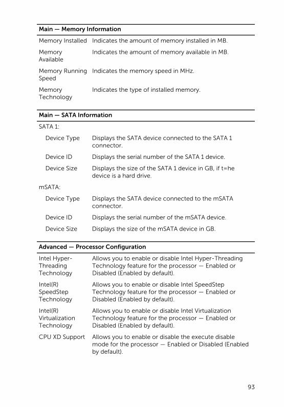
Main — Memory Information
Memory Installed Indicates the amount of memory installed in MB.
Memory Available
Indicates the amount of memory available in MB.
Memory Running Speed
Indicates the memory speed in MHz.
Memory Technology
Indicates the type of installed memory.
Main — SATA Information
SATA 1:
Device Type Displays the SATA device connected to the SATA 1 connector.
Device ID Displays the serial number of the SATA 1 device.
Device Size Displays the size of the SATA 1 device in GB, if t=he device is a hard drive.
mSATA:
Device Type Displays the SATA device connected to the mSATA connector.
Device ID Displays the serial number of the mSATA device.
Device Size Displays the size of the mSATA device in GB.
Advanced — Processor Configuration
Intel Hyper-Threading Technology
Allows you to enable or disable Intel Hyper-Threading Technology feature for the processor — Enabled or Disabled (Enabled by default).
Intel(R) SpeedStep Technology
Allows you to enable or disable Intel SpeedStep Technology feature for the processor — Enabled or Disabled (Enabled by default).
Intel(R) Virtualization Technology
Allows you to enable or disable Intel Virtualization Technology feature for the processor — Enabled or Disabled (Enabled by default).
CPU XD Support Allows you to enable or disable the execute disable mode for the processor — Enabled or Disabled (Enabled by default).
93
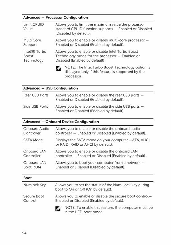
Advanced — Processor Configuration
Limit CPUID Value
Allows you to limit the maximum value the processor standard CPUID function supports — Enabled or Disabled (Disabled by default).
Multi Core Support
Allows you to enable or disable multi-core processor — Enabled or Disabled (Enabled by default).
Intel(R) Turbo Boost Technology
Allows you to enable or disable Intel Turbo Boost Technology mode for the processor — Enabled or Disabled (Enabled by default)
NOTE: The Intel Turbo Boost Technology option is displayed only if this feature is supported by the processor.
Advanced — USB Configuration
Rear USB Ports Allows you to enable or disable the rear USB ports — Enabled or Disabled (Enabled by default).
Side USB Ports Allows you to enable or disable the side USB ports — Enabled or Disabled (Enabled by default).
Advanced — Onboard Device Configuration
Onboard Audio Controller
Allows you to enable or disable the onboard audio controller — Enabled or Disabled (Enabled by default).
SATA Mode Displays the SATA mode on your computer —ATA, AHCI or RAID (RAID or AHCI by default).
Onboard LAN Controller
Allows you to enable or disable the onboard LAN controller — Enabled or Disabled (Enabled by default).
Onboard LAN Boot ROM
Allows you to boot your computer from a network — Enabled or Disabled (Disabled by default).
Boot
Numlock Key Allows you to set the status of the Num Lock key during boot to On or Off (On by default).
Secure Boot Control
Allows you to enable or disable the secure boot control—Enabled or Disabled (Enabled by default).
NOTE: To enable this feature, the computer must be in the UEFI boot mode.
94
Boot
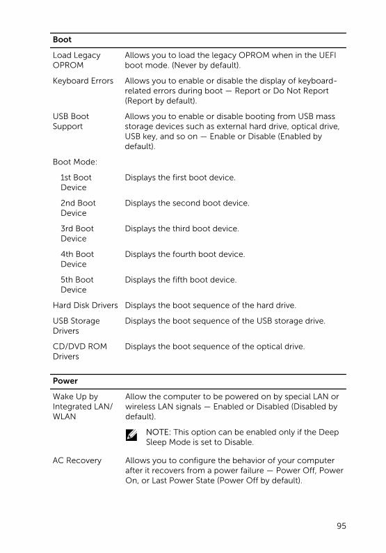
Load Legacy OPROM
Allows you to load the legacy OPROM when in the UEFI boot mode. (Never by default).
Keyboard Errors Allows you to enable or disable the display of keyboard-related errors during boot — Report or Do Not Report (Report by default).
USB Boot Support
Allows you to enable or disable booting from USB mass storage devices such as external hard drive, optical drive, USB key, and so on — Enable or Disable (Enabled by default).
Boot Mode:
1st Boot Device
Displays the first boot device.
2nd Boot Device
Displays the second boot device.
3rd Boot Device
Displays the third boot device.
4th Boot Device
Displays the fourth boot device.
5th Boot Device
Displays the fifth boot device.
Hard Disk Drivers Displays the boot sequence of the hard drive.
USB Storage Drivers
Displays the boot sequence of the USB storage drive.
CD/DVD ROM Drivers
Displays the boot sequence of the optical drive.
Power
Wake Up by Integrated LAN/WLAN
Allow the computer to be powered on by special LAN or wireless LAN signals — Enabled or Disabled (Disabled by default).
NOTE: This option can be enabled only if the Deep Sleep Mode is set to Disable.
AC Recovery Allows you to configure the behavior of your computer after it recovers from a power failure — Power Off, Power On, or Last Power State (Power Off by default).
95
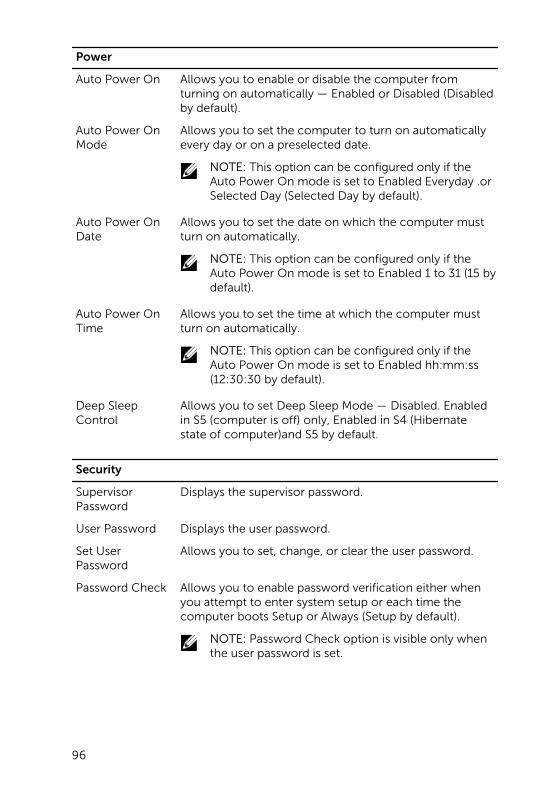
Power
Auto Power On Allows you to enable or disable the computer from turning on automatically — Enabled or Disabled (Disabled by default).
Auto Power On Mode
Allows you to set the computer to turn on automatically every day or on a preselected date.
NOTE: This option can be configured only if the Auto Power On mode is set to Enabled Everyday .or Selected Day (Selected Day by default).
Auto Power On Date
Allows you to set the date on which the computer must turn on automatically.
NOTE: This option can be configured only if the Auto Power On mode is set to Enabled 1 to 31 (15 by default).
Auto Power On Time
Allows you to set the time at which the computer must turn on automatically.
NOTE: This option can be configured only if the Auto Power On mode is set to Enabled hh:mm:ss (12:30:30 by default).
Deep Sleep Control
Allows you to set Deep Sleep Mode — Disabled. Enabled in S5 (computer is off) only, Enabled in S4 (Hibernate state of computer)and S5 by default.
Security
Supervisor Password
Displays the supervisor password.
User Password Displays the user password.
Set User Password
Allows you to set, change, or clear the user password.
Password Check Allows you to enable password verification either when you attempt to enter system setup or each time the computer boots Setup or Always (Setup by default).
NOTE: Password Check option is visible only when the user password is set.
96
Security
Set Supervisor Password
Allows you to set, change, or delete the supervisor password. The supervisor password controls access to the system setup utility.
NOTE: Deleting the supervisor password deletes the user password. Set the supervisor password before setting the user password.
User Access Level
Allows you to restrict or provide access to the system setup utility — No Access, View Only, Limited, or Full Access (Full Access by default).
• No Access: Restricts users from editing system setup options
• View Only: Allows users to only view system setup options
• Limited: Allows users to edit limited system setup options
• Full Access: Allows users to edit all system setup options except the supervisor password
Exit
Save Changes and Reset
Allows you to exit system setup and save your changes.
Discard Changes and Reset
Allows you to exit system setup and load previous values for all system setup options.
Load Defaults Allows you to load default values for all system setup options.
Overview
CAUTION: Unless you are an expert computer user, do not change the settings in the system setup program. Certain changes can make your computer work incorrectly.
NOTE: Before you change system setup, it is recommended that you write down the system setup screen information for future reference.
Use system setup to:
• Get information about the hardware installed in your computer, such as the amount of RAM, the size of the hard drive, and so on.
97
• Change the system configuration information.
• Set or change a user-selectable option, such as the user password, type of hard drive installed, enabling or disabling base devices, and so on.
Entering System Setup
1 Turn on (or restart) your computer.
2 During POST, when the DELL logo is displayed, watch for the F2 prompt to appear and then press F2 immediately.
NOTE: The F2 prompt indicates that the keyboard has initialized. This prompt can appear very quickly, so you must watch for it, and then press F2. If you press F2 before the F2 prompt, this keystroke
is lost. If you wait too long and the operating system logo appears, continue to wait until you see the operating system’s desktop. Then, turn off your computer and try again.
98
Clearing Forgotten PasswordsWARNING: Before working inside your computer, read the safety information that shipped with your computer and follow the steps in Before Working Inside Your Computer. After working inside your computer, follow the instructions in After Working Inside Your Computer. For more safety best practices, see the Regulatory Compliance home page at dell.com/regulatory_compliance.
1 Remove the base cover.
2 Follow the procedure from step 2 to step 3 in “Removing the System Board”.
3 Replace the base cover.
4 Turn on the computer to clear all BIOS passwords.
5 Remove the base cover.
6 Follow the procedure from step 3 to step 4 in “Replacing the System Board”.
7 Replace the base cover.
99
Clearing CMOS SettingsWARNING: Before working inside your computer, read the safety information that shipped with your computer and follow the steps in Before Working Inside Your Computer. After working inside your computer, follow the instructions in After Working Inside Your Computer. For more safety best practices, see the Regulatory Compliance home page at dell.com/regulatory_compliance.
1 Remove the base cover.
2 Follow the procedure given in step 1 in “Removing the Coin-Cell Battery”.
3 Wait for approximately five seconds to clear the CMOS settings.
4 Follow the procedure given in step 2 in “Replacing the Coin-Cell Battery”.
5 Replace the base cover.
100
Display-Settings ControlsUse the display settings controls to:
• adjust volume
• adjust screen brightness
• select video source
• turn off the display
The functions of the controls vary when:
• your computer is not connected to any video input or video output devices
• your computer is connected to an external video input device such as an another computer, gaming console, camera, Blu-ray player, and so on
• your computer is connected to an external video output device such as a TV, monitor, projector, and so on
101
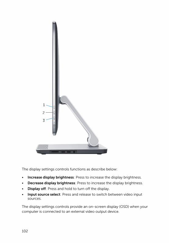
The display settings controls functions as describe below:
• Increase display brightness: Press to increase the display brightness.
• Decrease display brightness: Press to increase the display brightness.
• Display off: Press and hold to turn off the display.
• Input source select: Press and release to switch between video input sources.
The display settings controls provide an on-screen display (OSD) when your computer is connected to an external video output device.
102
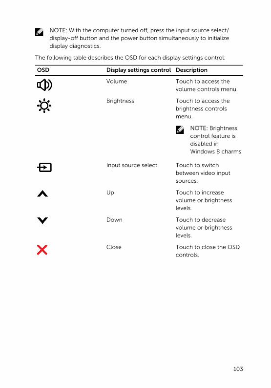
NOTE: With the computer turned off, press the input source select/display-off button and the power button simultaneously to initialize display diagnostics.
The following table describes the OSD for each display settings control:
OSD Display settings control Description
Volume Touch to access the volume controls menu.
Brightness Touch to access the brightness controls menu.
NOTE: Brightness control feature is disabled in Windows 8 charms.
Input source select Touch to switch between video input sources.
Up Touch to increase volume or brightness levels.
Down Touch to decrease volume or brightness levels.
Close Touch to close the OSD controls.
103
Flashing the BIOSYou may need to flash (update) the BIOS when an update is available or when you replace the system board. To flash the BIOS:
1 Turn on the computer.
2 Go to dell.com/support.
3 If you have your computer's Service Tag, type your computer's Service Tag and click Submit.
If you do not have your computer's Service Tag, click Detect My Product to allow automatic detection of the Service Tag.
NOTE: If the Service Tag cannot be detected automatically, select your product under the product categories.
4 Click Get Drivers and Downloads.
5 Click View All Drivers.
6 In the Operating System drop-down, select the operating system installed on your computer.
7 Click BIOS.
8 Click Download File to download the latest version of the BIOS for your computer.
9 On the next page, select Single-file download and click Continue.
10 Save the file and once the download is complete, navigate to the folder where you saved the BIOS update file.
11 Double-click the BIOS update file icon and follow the instructions on the screen.
104
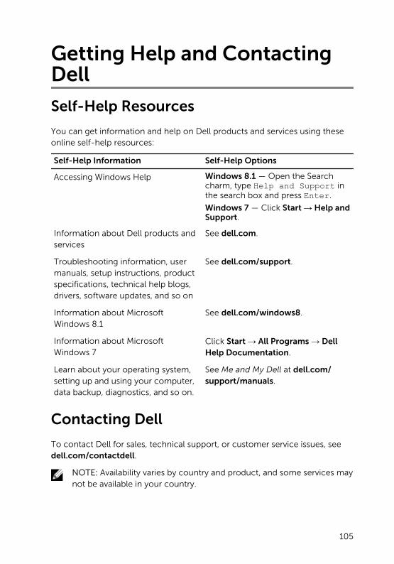
Getting Help and Contacting Dell
Self-Help Resources
You can get information and help on Dell products and services using these online self-help resources:
Self-Help Information Self-Help Options
Accessing Windows Help Windows 8.1 — Open the Search charm, type Help and Support in the search box and press Enter.
Windows 7 — Click Start → Help and Support.
Information about Dell products and services
See dell.com.
Troubleshooting information, user manuals, setup instructions, product specifications, technical help blogs, drivers, software updates, and so on
See dell.com/support.
Information about Microsoft Windows 8.1
See dell.com/windows8.
Information about Microsoft Windows 7
Click Start → All Programs → Dell Help Documentation.
Learn about your operating system, setting up and using your computer, data backup, diagnostics, and so on.
See Me and My Dell at dell.com/support/manuals.
Contacting Dell
To contact Dell for sales, technical support, or customer service issues, see dell.com/contactdell.
NOTE: Availability varies by country and product, and some services may not be available in your country.
105

NOTE: If you do not have an active internet connection, you can find contact information on your purchase invoice, packing slip, bill, or Dell product catalog.
106