Embed Size (px)
Citation preview


Inspector Pocket Guide
The following information is intended to provide construction and code enforcement professionals with basic checkpoints to ensure that the required fire resistance ratings are maintained when through penetrations and linear joints breach walls and floors.
This inspection guideline is not intended to be all encompassing or to be used as a design guide. It is for information and educational purposes only.
The Source of Firestop ExpertiseSM

3
Firestopping Inspection Manual
International FireStop Council - www.firestop.org - 877.241.3769
Sections:
Building Code Requirements .................... 4
Plan Review Process .................................... 5
Engineering Judgments ............................. 6
Inspection Process ....................................... 7
Field Inspection Process ............................. 8
Guidelines forPenetration Systems ................................... 10
Guidelines forJoint Systems ............................................... 12
Guidelines forCurtain Walls ................................................ 14
Duct Enclosures ........................................... 18
Plan Review andInspection Process ...................................... 20
Testing Laboratories .................................. 21
Tableof
Contents
Fifth Edition

Lorem Ipsum
4 International FireStop Council - www.firestop.org - 877.241.3769
Firestopping Inspection Manual
Scope
Construction codes have very clear require-ments on passive fire protection. These require-ments are included in Chapter 7 Fire and Smoke Protection Features of the International Code Council (ICC) International Building Code© (IBC©).
Whenever required by the IBC©, the fire resistance ratings of floors, walls, floor/ceiling, roof/ceiling assemblies or fire-resistance-rated duct enclosures must be restored when an open-ing is made to accommodate penetrations for mechanical, electrical, plumbing, communication systems and ventilation ducts. joints between floors, walls, floors and walls, etc, must also have the same fire resistance ratings as the adjacent construction.
NFPA 101 (Life Safety Code), NFPA 70 (National Electric Code), the International Mechanical Code© (IMC©) and the International Plumbing Code© (IPC©) also include provisions related to the protection of penetrations. The codes have explicit requirements for inspection of firestop systems before they are concealed.
The IBC 2012 107.2.2 requires that evidence be submitted to the building official showing that the materials and methods of construction used to protect penetrations, joints and ventilation ducts in fire resistance rated building elements shall not reduce the required fire resistance rating. The International Fire Code© has require-ments for periodic inspection of firestop systems throughout the life of the building.
Building Code Requirements
Lorem Ipsum
5International FireStop Council - www.firestop.org - 877.241.3769
Firestopping Inspection ManualScope
The authority having jurisdiction (AHJ) must review and approve firestop system details and rated ducted enclosures. Hence, firestop systems details and materials must be included on the plans and specifications. Manufacturer’s cut sheets are often accepted if they are generated by an approved testing agency. If details, products and specifications are not sufficient to provide clear directions to the general contractor and firestop installer, the submittals should be noted as incomplete and returned to the designer to be resubmitted with the required information. If the plans and specifications are clear and complete, most field problems with firestop systems can be avoided.
Plans Examination / Review

Lorem Ipsum
6 International FireStop Council - www.firestop.org - 877.241.3769
Firestopping Inspection Manual
Scope
Engineering Judgments
It is not unusual to find, in construction projects, unique conditions which have not been tested and listed, that require special consideration. The protection of these conditions will necessitate Engineering Judgments (EJ’s) since they have not been tested and do not comply with a published design listing.
The International Firestop Council has published “Recommended IFC Guidelines for Evaluating Firestop Systems in Engineering Judgments” to assist designers, plan reviewers and inspectors in addressing nonconforming construction details. The plan submittals should always indicate which details are based on EJ’s. The submitted EJ’s need to be approved by the building official, and made available to the field inspector when approved.
The IFC guidelines for the evaluation of EJ’s can be obtained from the IFC website: www.firestop.org

Lorem Ipsum
7International FireStop Council - www.firestop.org - 877.241.3769
Firestopping Inspection ManualScope
The time allocated for inspections can be drastically reduced if the proper paperwork is provided on the approved plans. Planning and communication between the building designer, structural engineer and the installer prior to construction will save time, costs and resources in assuring the application of the proper systems.
Verification of system testing and listings with a nationally recognized laboratory, prior to installation in the field, is key to a smooth inspection process. Use of applicable ASTM practices will provide guidelines for inspection of installed systems.
Inspection Process

Lorem Ipsum
8 International FireStop Council - www.firestop.org - 877.241.3769
Firestopping Inspection Manual
The ability of penetration firestop systems, fire resistive joint systems and ventilation systems to perform their intended function of fire containment is directly related to the quality of their installations. Thorough inspection is an integral component of any passive fire protection quality control program. It is not realistic to visually inspect each penetration and the entire length of every joint and ventilation duct. How many inspections are enough? This is a judgment call by the inspector; however, the ASTM inspection standards may be used as a guideline.
Field Inspection Process
Scope
Major elements of quality firestop inspections are:
• Firestop systems must not be concealed from view before being inspected and approved (IBC 110.3.6).
• Walk through visual inspections should be made during the rough and final inspections.
• When necessary or required, destructive evaluation will be made on various types of firestop systems.
• Appropriate tools for firestop inspections should include a flashlight, measuring device and cutting tool.
• Proper material depths, annular space, at-tachments, spacing and product type are critical to the effectiveness of the system.

Lorem Ipsum
9International FireStop Council - www.firestop.org - 877.241.3769
Firestopping Inspection ManualScope
• Construction documents detailing the fire-stop locations and systems must be kept on site to assist in the conduct of the inspection.
• Insure to a reasonable degree that empty containers, wrappings or boxes of the speci-fied materials are in sufficient quantity to have been installed correctly.
• Insure to a reasonable degree that the actual products, containers, wrappings or boxes are labeled with the approved testing agency marks and are as specified in the submitted details.
• Measure the depth and width of materials as indicated in the details (sometimes density measurements are also required for products such as thermal insulation).
• Insure to a reasonable degree that joints have been installed in such manner that the required movement can be achieved.
• Compare the installed firestop system with the approved submitted details.
• Insure a reasonable degree of workmanship, which would indicate compliance with the specified design.

10
Step One:
Firestopping Inspection Manual
International FireStop Council - www.firestop.org - 877.241.3769
Guidelines
Step Two:
Step Three:
Verify the documents and submitted drawings reference tested and listed applicable through and membrane penetration assemblies containing sealants, devices and/or other materials tested to ASTM E814 or UL 1479 by accredited testing agencies. These systems should be published and readily available via the internet or other means.
Verify that the Through-Penetration System being used has been tested to the hourly rating necessary (ie. 1 hr., 2 hr., etc,) based on the type of assembly being penetrated.
As an overview of these steps, verify that the parameters indicated in the system are the same as those installed in the field: Is the through penetration system rated for the type and nature of assembly (thickness of concrete, stud width, etc.)?
ForPenetrationFirestop Systems

11
Firestopping Inspection Manual
International FireStop Council - www.firestop.org - 877.241.3769
A. Is the rating of the through penetration system equal or greater than the assembly penetrated?
B. Do the supplied products have labels from a recognized quality assurance agency?
C. Does the field installation follow the listing?
a. For the size of opening prior to firestopping?
b. For pipe conditions: Nature and quantity of penetrant(s), (material, size, diameter, insulation type & thickness, etc.)? For cable conditions: Allowable cable sizes, jacketing, spacing and bundle size or percent fill of opening (as listed)?
c. Annular space requirements, (minimum, maximum, nominal, etc.)?
d. Specified forming, packing or backing material, (when required)?
e. Specified sealant, coating, device or firestopping product indicated, (type, amount, depth, location, etc.)?
f. Specified accessory items, (anchors, fasteners, securing devices, plates, etc.)?
Overview:
Guidelines

12
Step One:
Firestopping Inspection Manual
International FireStop Council - www.firestop.org - 877.241.3769
Guidelines
Step Two:
Verify the rating of the joint system is equal to the rating of the assemblies it is connecting. The code requires that the rating of a joint system shall not be less than the fire resistive ratings of the adjacent assemblies.
Step Three:
Verify the documents and submitted drawings reference systems that have been tested for the required amount of movement. A system listing a nominal 1 inch joint width with 25% compression or extension, actually allows for a movement of 1/4” of compression and 1/4” of extension.
Verify the documents and submitted drawings have been reviewed by the Project Design Professional and/or the structural engineer and that they meet the allowable movement requirements.
Verify the documents and submitted drawings reference tested and listed fire resistive joint systems tested to ASTM E1966 or UL 2079 by accredited testing laboratories or certified third party testing agencies. These systems should be published or readily available via the internet or other means.
For Fire Resistive Joint Systems:Including MechanicalFire Barrier Systems
Step Four:

13
Firestopping Inspection Manual
International FireStop Council - www.firestop.org - 877.241.3769
A. Is the joint system tested and listed?
B. Is the joint system tested for the amount of movement required?
C. Is the joint system tested for the class and type of movement required?
D. Is the fire rating of the joint equal to (or greater than) the assemblies it is adjacent to?
E. Observe the nominal installed width of the joint at the framing inspection.
F. If a mechanical system is used, are the specified tracks installed with a third party testing agency label attached?
G. Do the supplied products have labels from recognized quality assurance agency?
H. Does the field installation follow the listing?
a. Specified forming, packing or backing material?
b. Specified type of sealant, coating or device?
c. Specified amount, depth, location of sealant, coating or device?
d. Specified accessory items – cover plates, bond breaker tape, and specified deflection track?
Overview:
Guidelines
As an overview of these steps, verify the parameters indicated in the system are the same as those installed in the field: (Download checklist form at the IFC web site www.firestop.org).

14
Step One:
Firestopping Inspection Manual
International FireStop Council - www.firestop.org - 877.241.3769
Guidelines
Step Two:
Step Three:
Verify that the firestop material to be used is classified and listed for use in Perimeter Fire Barrier Systems. All other materials should not be used.
Verify the rating of the system is greater than or equal to the rating of the floor. The continuity requirements within the building codes state that the rating of a floor assembly must extend to and be tight against an exterior wall.
Verify documents and submitted drawings reference legitimate listed Perimeter Fire Barrier Systems. Documents referencing only fire resistive joint systems such as FF, FW or HW should not be accepted for curtain wall applications.
ForPerimeter Fire BarrierSystems (Curtain Walls)

15
Firestopping Inspection Manual
International FireStop Council - www.firestop.org - 877.241.3769
Guidelines
Verify insulation type and brand used is listed within the tested system. Mineral wool is the typical insulation of choice. If mineral wool is used it must be installed to the correct compression and according to the correct orientation.
Verify documents reference systems that have been tested with windows or vision glass if the building has glazing close to the safing area. Some systems were tested with glazing close to the safing area while other systems were for structures with limited glazing such as storage and warehouse facilities.
Verify a stiff steel reinforcement member, if required, has been placed behind exposed curtain wall panel insulation. Typical stiffening members can be steel hat channels, “L” or “T” angles.
Step Six:
Step Four:
Step Five:

16
Firestopping Inspection Manual
International FireStop Council - www.firestop.org - 877.241.3769
Step Eight:
Verify coating or sealant has been applied to the proper depth. A common inspection practice is to be on site just prior to the addition of the sealant to verify the correct application thickness is being followed and to verify correct orientation of mineral wool. The inspector may request samples from the installing contractor after which the installing contractor shall make the necessary repairs to the destructively sampled area. A scale or caliper is sufficient for measuring the sealant depth.
Step Nine:
Verify safing clips or “Z” clips have been used if the system requires it.
Verify that exposed mullions, if required by the system, are covered with the proper insulating barrier securely fastened with mechanical fasteners per the system design.
Step Ten:
Step Seven:
If required by the tested system, verify insulation panels are securely fastened with mechanical fasteners per the listed system.
Guidelines

Lorem Ipsum
17International FireStop Council - www.firestop.org - 877.241.3769
Firestopping Inspection Manual
As an overview of the above steps, verify the parameters indicated in the system are the same as those installed in the field: (Download checklist form from the IFC web site at www.firestop.org).
Overview:
Guidelines
A. Is the perimeter fire barrier system tested for the type and nature of assembly, (minimum thickness of concrete, transom spacing, etc.)?
B. Is the rating of the perimeter fire barrier system equal or greater than the floor assembly?
C. Do the supplied products have labels from a recognized quality assurance agency?
D. Does the field installation follow the listing?
a. Width of gap between floor edge and curtain wall at time of installation.
b. Design detail includes vision glass if applicable.
c. Specified curtain wall spandrel insulation, (type, thickness, density, etc.).
d. Specified spandrel panel perimeter angles, (gauge thickness, dimensions, fastener spacing).
e. Specified framing and/or mullion covering, (type, thickness, density, etc).
f. Support clips for safing insulation, if specified.
g. Specified forming or safing insulation, (type, % compression, depth, etc).
h. Specified sealant, coating, device or firestopping product, (type, depth, location).

18
Step One:
Firestopping Inspection Manual
International FireStop Council - www.firestop.org - 877.241.3769
Guidelines
Step Three:
Step Two:
Verify the fire resistance rating of the duct enclosure system and corresponding firestop system are equal or greater than the required fire resistance ratings for the building construction assembly penetrated.
For grease ducts, the IMC requires the fire resistance rating of the duct enclosure system be at least equivalent to the surrounding building
Verify the duct enclosure system is tested to the appropriate Standard for the specific type of duct system. Grease duct enclosure systems are tested and listed per ASTM E2336, which includes a full scale ASTM E 119 engulfment test. HVAC duct enclosure systems are tested and listed per ISO 6944, Type A is for closed duct systems and Type B is for duct systems that contain openings.
Verify the documents and submitted drawings reference legitimate fire resistive duct enclosure systems tested by accredited testing laboratories or certified third party testing agencies. These systems and insulation components should be listed, labeled, published and readily available via the internet or other means.
ForFire-Resistance-RatedDuct Enclosure Systems

19
Firestopping Inspection Manual
International FireStop Council - www.firestop.org - 877.241.3769
Guidelines
Verify the field installation is consistent with the parameters of the listing and therefore compliant.
A. Duct System Type – kitchen grease exhaust, hazardous material exhaust, ventilation, supply/ return, etc.
B. Duct Construction – dimensions, material, gauge, reinforcement, connections, vertical or horizontal orientation.
C. Enclosure System – labeled components, number of layers, fire rating, required clearance to combustibles, thickness and density of material, material joints (overlap of material, taping of cut edges or seams), etc.
D. Enclosure System Attachment – mechanical method of attachment to duct (typically steel banding and/or capacitor discharge insulation pins), components, spacing, gauge, etc.
E. Duct Supports – hanger system components, frequency of location, clearance to enclosure system, protection requirements.
F. Access Door – field fabricated or prefabricated door construction and protection with enclosure system material must match design listing.
G. Firestop System – refer to design listing for fire rated assembly construction, annular space, packing material type and depth, and firestop material type and depth.
Step Four:
construction assembly penetrated. The F and T ratings for the corresponding duct firestop system must also be at least equivalent to the duct enclosure system and the surrounding assembly. For HVAC ducts, the stability, integrity and fire resistance rating of the duct enclosure system must be at least equivalent to the rating of the construction assembly penetrated.
20
Firestopping Inspection Manual
International FireStop Council - www.firestop.org - 877.241.3769
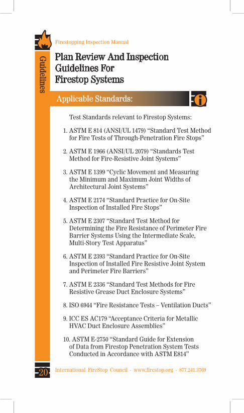
Test Standards relevant to Firestop Systems:
1. ASTM E 814 (ANSI/UL 1479) “Standard Test Method for Fire Tests of Through-Penetration Fire Stops”
2. ASTM E 1966 (ANSI/UL 2079) “Standards Test Method for Fire-Resistive Joint Systems”
3. ASTM E 1399 “Cyclic Movement and Measuring the Minimum and Maximum Joint Widths of Architectural Joint Systems”
4. ASTM E 2174 “Standard Practice for On-Site Inspection of Installed Fire Stops”
5. ASTM E 2307 “Standard Test Method for Determining the Fire Resistance of Perimeter Fire Barrier Systems Using the Intermediate Scale, Multi-Story Test Apparatus”
6. ASTM E 2393 “Standard Practice for On-Site Inspection of Installed Fire Resistive Joint System and Perimeter Fire Barriers”
7. ASTM E 2336 “Standard Test Methods for Fire Resistive Grease Duct Enclosure Systems”
8. ISO 6944 “Fire Resistance Tests – Ventilation Ducts”
9. ICC ES AC179 “Acceptance Criteria for Metallic HVAC Duct Enclosure Assemblies”
10. ASTM E-2750 “Standard Guide for Extension of Data from Firestop Penetration System Tests Conducted in Accordance with ASTM E814”
Plan Review And InspectionGuidelines For Firestop Systems
Applicable Standards:
Guidelines

21
Firestopping Inspection Manual
International FireStop Council - www.firestop.org - 877.241.3769
There are several independent testing laboratories, also referred to as third party testing agencies, which conduct the fire testing of firestop, perimeter fire barrier and duct enclosure systems. The fire test results are usually included as design listings in the fire resistance directories published by the testing laboratory. These Directories are an important source of information during the plan review process and inspection process. The following are some of the recognized independent laboratories conducting tests of firestop systems:
1. Underwriters Laboratories Inc. Northbrook, IL (847) 272-8800 www.ul.com
2. Southwest Research Institute San Antonio, TX (210) 522-2311 www.fire.swri.org
3. Factory Mutual Norwood, MA (781) 762-4300 www.fmglobal.com
4. Intertek Testing Services San Antonio, TX (210) 625-8100 www.intertek.com
Directories
Third Party Testing Agencies:
IndependentTesting
Laboratories
4.

22
Firestopping Inspection Manual
International FireStop Council - www.firestop.org - 877.241.3769
Penetrations:
Firestopping Guidelines
Firestop Systems Identification Guide
PenetrantConcrete Floor Concrete WallUL ITS UL ITS
Blank Openings CAJ 0###FS500-699FG
CAJ 0### WJ 0###
FS500-699WG
Metallic CAJ 1###FS500-699FA
CAJ 1### WJ 1###
FS100-299WA
Nonmetallic CAJ 2###FS500-699FB
CAJ 2### WJ 2###
FS100-299WB
Cables CAJ 3###FS500-699FD
CAJ 3### WJ 3###
FS100-299WD
Cable Trays CAJ 4###FS500-699FD
CAJ 4### WJ 4###
FS100-299WD
Insulated Metal CAJ 5###FS500-699FC
CAJ 5### WJ 5###
FS100-299WC
Bus Duct CAJ 6###FS500-699FE
CAJ 6### WJ 6###
FS100-299WE
Metal Ducts w/o Dampers
CAJ 7### TBDCAJ 7### WJ 7###
TBD
Mixed Multiple CAJ 8### TBDCAJ 8### WJ 8###
TBD
PenetrantGypsum Wall
Wood OrSteel Framed Floor
UL ITS UL ITS
Blank Openings WL 0###FS100-299WG
FC 0### FE 0###
FS100-299FG
Metallic WL 1###FS100-299WA
FC 1### FE 1###
FS100-299FA
Nonmetallic WL 2###FS100-299WB
FC 2### FE 2###
FS100-299FB
Cables WL 3###FS100-299WD
FC 3### FE 3###
FS100-299FD
Cable Trays WL 4###FS100-299WD
FC 4### FE 4###
FS100-299FD
Insulated Metal WL 5###FS100-299WC
FC 5### FE 5###
FS100-299FC
Bus Duct WL 6###FS100-299WE
FC 6### FE 6###
FS100-299FE
Metal Ducts w/o Dampers
WL 7### TBDFC 7### FE 7###
TBD
Mixed Multiple WL 8### TBDFC 8### FE 8###
TBD
Lorem Ipsum
23International FireStop Council - www.firestop.org - 877.241.3769
Firestopping Inspection ManualFirestopping G
uidelines
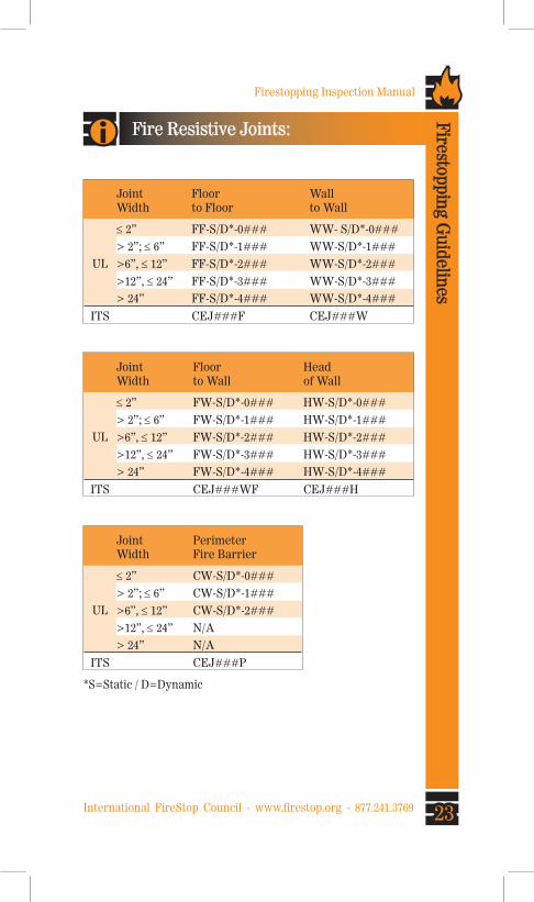
Fire Resistive Joints:
JointWidth
Floor to Floor
Wallto Wall
UL
≤ 2” FF-S/D*-0### WW- S/D*-0###
> 2”; ≤ 6” FF-S/D*-1### WW-S/D*-1###
>6”, ≤ 12” FF-S/D*-2### WW-S/D*-2###
>12”, ≤ 24” FF-S/D*-3### WW-S/D*-3###
> 24” FF-S/D*-4### WW-S/D*-4###
ITS CEJ###F CEJ###W
JointWidth
Floorto Wall
Headof Wall
UL
≤ 2” FW-S/D*-0### HW-S/D*-0###
> 2”; ≤ 6” FW-S/D*-1### HW-S/D*-1###
>6”, ≤ 12” FW-S/D*-2### HW-S/D*-2###
>12”, ≤ 24” FW-S/D*-3### HW-S/D*-3###
> 24” FW-S/D*-4### HW-S/D*-4###
ITS CEJ###WF CEJ###H
JointWidth
PerimeterFire Barrier
UL
≤ 2” CW-S/D*-0###
> 2”; ≤ 6” CW-S/D*-1###
>6”, ≤ 12” CW-S/D*-2###
>12”, ≤ 24” N/A
> 24” N/A
ITS CEJ###P
*S=Static / D=Dynamic

Lorem Ipsum
24 International FireStop Council - www.firestop.org - 877.241.3769
Firestopping Inspection Manual
Firestopping Guidelines
Building & Safety Codes:
International Building Code (IBC) 2012 Edition107.2.2 Submittal Fire Shop Drawings
110.3.6 Fire & Smoke penetrations
202 Definations Fire-Resistant Joint Through-Penetration Firestop System
705.5 Exterior Wall Fire-Resistance rating
705.9 Exterior Wall Joints
706.5 Fire Walls Horizontal continuity
706.6 Fire Walls Vertical continuity
706.9 Fire Wall Penetrations (see Section 714)
706.10 Fire Wall Joints (see Section 715)
707.5 Fire Barrier continuity
707.7 Fire Barrier Penetrations (see Section 714)
707.8 Fire Barrier Joints (see Section 715)
708.7 Fire Partitions Penetrations (see Section 714)
708.9 Fire Partitions Joints (see Section 715)
709.3 Smoke Barrier 1 Hour Fire-resistance rated
709.4 Smoke Barrier continuity
709.7 Smoke Barrier Penetrations (see Section 714)
709.8 Smoke Barrier Joints (see Section 715)
710.6 Smoke Partition Penetrations “approved material”
710.7 Smoke Partition Joints “approved material”
711.4 Horizontal Assemblies continuity
711.5 Horizontal AssembliesPenetrations (Section 714)
711.6 Horizontal Assemblies Joints (Section 715)
712.1.4 Vertical AssembliesPenetrations (Section 714)
712.1.11 Vertical Assemblies Joints (Section 715)
714 Penetrations
714.3.1.2 ASTM E-814 or UL1479
714.3.2 Membrane Penetrations
714.4.1.1.2 Through-Penetrations E-814 or UL1479
714.4.1.1.2 requires F&T In Floors
714.3.1.2 Wall Penetrations required F rating
715 Fire-Resistant Joint System
715.1.1 Curtain Wall Assembly (accordance with Section 715.4)
715.3 Test Criteria ASTM E-1966 or UL2079
715.4 Exterior Curtain Wall / Floor intersection
715.6 in Smoke Barriers air leakage <5 (UL 2079)

Lorem Ipsum
25International FireStop Council - www.firestop.org - 877.241.3769
Firestopping Inspection ManualFirestopping G
uidelines
International Building Code (IBC) 2009 Edition702 Definitions
712.2 Installation Details
712.3.1.2 Through Penetration Firestop
712.3.2 Membrane Penetrations
712.3.3 Ducts
712.3.4 Dissimilar material
712.4.1.1.2 Through Penetration Firestop
712.4.1.2 Membrane penetrations
712.4.1.3 Ducts
712.4.1.4 Dissimilar material
712.5 Smoke Barriers
714.1 Joints
714.2 Installation (Joints)
714.3 Fire Test (Joints)
714.4 Curtain Wall
714.5 Spandrel Wall
714.6 Joints (Smoke)
NFPA 101, “Life Safety Code”; 2009 Edition8.3.5 Penetrations
8.3.5.1 Firestop Systems and Devices Required
8.3.5.1.3 Penetrations
8.3.5.1.4 Penetrations
8.3.5.2 Sleeves
8.3.5.3 Insulation and Coverings
8.3.5.5.1 Dissimilar Material
8.3.5.6.1 Membrane penetrations
8.3.5.6.2 Membrane penetrations
8.3.5.6.3 Outlet boxes
8.3.6 and 8.3.6.1 Joints
8.3.6.2 Joints and smoke
8.3.6.3 Joints and smoke
8.3.6.4 Representative joints
8.3.6.5 Joints and Test Standards
8.3.6.6 Joint and Test Standards
8.3.6.7 Curtain Walls and Perimeter Joints
8.3.6.7.2 Curtain Wall
8.4.4 and 8.4.4.1 Penetrations in smoke partitions
8.4.5 and 8.4.5.1 Joints and smoke partitions
A.8.3.5.1 Inspections – penetrations


Lorem Ipsum
28 International FireStop Council - www.firestop.org - 877.241.3769
Firestopping Inspection Manual
Firestopping Guidelines
About the International Code Council
The International Code Council is a member-fo-cused association dedicated to helping the build-ing safety community and construction industry provide safe, sustainable and affordable construc-tion through the development of codes and stan-dards used in the design, build and compliance process. Most U.S. communities and many global markets choose the International Codes. ICC Evaluation Service (ICC-ES), a subsidiary of the International Code Council, has been the industry leader in performing technical evaluations for code compliance fostering safe and sustainable design and construction.
Headquarters: 500 New Jersey Avenue, NW, 6th Floor,
Washington, DC 20001-2070
District Offices: Birmingham, AL; Chicago. IL; Los Angeles, CA
1-888-422-7233www.iccsafe.org

Lorem Ipsum
29International FireStop Council - www.firestop.org - 877.241.3769
Firestopping Inspection ManualFirestopping G
uidelines
Notes:

Lorem Ipsum
30 International FireStop Council - www.firestop.org - 877.241.3769
Firestopping Inspection Manual
Firestopping Guidelines
Notes:

Lorem Ipsum
31International FireStop Council - www.firestop.org - 877.241.3769
Firestopping Inspection ManualFirestopping G
uidelines
Notes: