Embed Size (px)
Citation preview
Installation, Operation, and Troubleshooting Manual for
Inside DIRECT-PLUMBED® Containment Tanks
Models
2478SQ-NA-DP 1100Lb/150Gal Containment Tank3072-NA-DP 1500Lb/200Gal Containment Tank4280-NA-DP 2650Lb/353Gal Containment Tank
About this manualRead this manual for the following information about inside Direct-Plumbed containment tanks:• installation• operation• troubleshooting
Store this manual in a safe place for future reference.
About Frontline International, Inc. • Through a dedication to the development, manufacture, and delivery of quality cooking oil management systems, Frontline
International, Inc. remains a leading global source for equipment solutions that safely and efficiently dispense, contain, monitor, extract, transport, or filter cooking oil for immediate on-premise recycling and use.
• A stakeholder focused organization, our sustainability relies on initiatives that benefit associates, customers and community – from responsible manufacturing techniques to conservation of resources and performance metrics.
• With our valued network of service and installation experts our branded and custom products enhance productivity, improve operations and save costs for professionals within foodservice, hospitality, and other markets around the world, every day.
© 2012 Frontline International, Inc.
Specifications subject to change without notice.
Direct-Plumbed is a registered trademark of Frontline International, Inc.
Table of contents Before you begin .................................................................................... 1Read me first .......................................................................................... 1Installation tools and materials ............................................................. 1Installation ............................................................................................. 2Unit placement ...................................................................................... 2Outlet pipe installation .......................................................................... 2Install fittings on top of storage tank .................................................... 2Lowering the collection port ................................................................. 4Plumb into ceiling .................................................................................. 5Electrical connection .............................................................................. 6Standard electrical connection .............................................................. 6Remote electrical connection ................................................................ 6Connect wires to the tank ...................................................................... 6Plumbing fryers to containment tank ................................................... 7Guidelines for plumbing fryers .............................................................. 7Plumbing specifications ........................................................................ 8Installation of the manifold assembly................................................... 8Connecting the tank to the Direct-Plumbed system .......................... 10Direct-Plumbed operation................................................................... 10Maintenance ........................................................................................ 11Tank cleaning ...................................................................................... 11Heater replacement ............................................................................. 11Wire diagram for control panel .......................................................... 13Warranty ..............................................................................................BC
1Inside Direct-Plumbed® Containment Tanks | Frontline International Inc.
Installation tools and materialsRead this section to see a list of installation:• tools needed• materials included in tank installation kit
Before you beginRead this section for:• important Read me first information you should know before you begin installation• list of installation tools and materials you need• list of installation materials in the tank installation kit
Read me firstRead and understand the following before beginning installation:• To use the Direct-Plumbed system, the fryer must have built in filtration that already has or can be upgraded with a rear waster oil disposal kit.• If a fryer does not have a built in filtration, the Direct-Plumbed system can be used by implementing a Frontline Waste Oil Pump Station.• The installer must read and completely understanding these directions before beginning the system installation.• Failure to understand and follow these directions may result in injuries to the installer, bystanders, and/or the equipment.• Use caution to avoid wiring, pipes, etc. in walls when drilling holes.• Read, understand, and follow the manufacturer’s directions for all tools and equipment being used to ensure safety.• Use only the proper equipment for the task being performed.• Ensure that all construction debris and dust is removed when installation is complete.
Installation tools and materialsRead this section to see a list of installation:• tools needed• materials included in tank installation kit
The installation tool list includes: • Electric Drill• 3/8” or 1/2” Pilot Bit• 2-1/2” to 3” Hole Saw• Hammer Drill• 3/8” or 1/2” Masonry Pilot Bit• 2-1/2” to 3” Masonry Core Bit• 18” and 24” Pipe Wrench• Hacksaw• 9/16” Socket/Ratchet and Wrench• Flat Blade Screwdriver or 5/16” Nut Driver• Caulking Gun• 50’ & 100’ Extension Cord• 24” Level• Permanent Marker• 4’ or 6’ Ladder• Paper Towels or Rags The installation materials list includes: • Pipe thread sealant• Silicone caulking
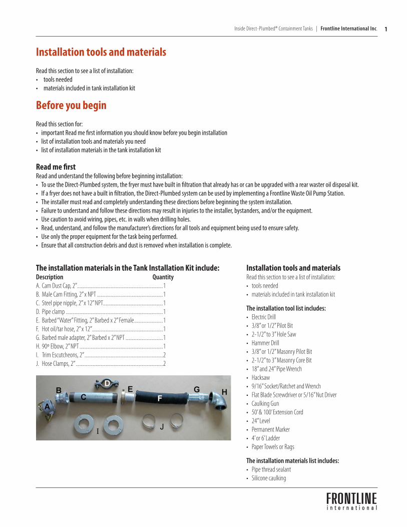
The installation materials in the Tank Installation Kit include: Description QuantityA. Cam Dust Cap, 2” .....................................................................1B. Male Cam Fitting, 2” x NPT .....................................................1C. Steel pipe nipple, 2” x 12” NPT................................................1 D. Pipe clamp ..............................................................................1E. Barbed “Water” Fitting, 2” Barbed x 2” Female .......................1F. Hot oil/tar hose, 2” x 12” .........................................................1G. Barbed male adapter, 2” Barbed x 2” NPT ..............................1H. 90º Elbow, 2” NPT ...................................................................1I. Trim Escutcheons, 2” ...............................................................2J. Hose Clamps, 2” ......................................................................2
2 Frontline International Inc. | Inside Direct-Plumbed® Containment Tanks
!
InstallationRead this section for information about:• unit placement• outlet pipe installation either on top of a storage tank, by lowering the collection port, or plumbing into ceiling• electrical connection that is either standard or remote• plumbing fryers to the containment tank• plumbing specifications• installation of manifold assembly• connecting the containment talk to the Direct-Plumbed system
Unit placementRead this section for important information about unit placement. Follow these directions concerning unit placement:• The installer should confirm with the restaurant manager/owner the location for the storage tank.• Keep a 31” wide by 31” deep area that is required for the installation of the storage tank.• Exterior wall consideration - be sure the unit can be placed against an exterior wall. If not, extra piping is required to complete the
outlet installation.• Consider the relationship of the storage tank to the fryer.• Outside obstruction consideration - note any obstructions on the outside of the wall that will obstruct installation of the outlet pipe.• Wall obstruction consideration - note any obstructions inside the wall that will prevent installation of the outlet pipe.
Outlet pipe installationRead this section for information about how to install the outlet pipe either to:• install fittings on top of the storage tank• lower the collection port• plumb into the ceiling
Note: Always peel the white laser film from all stainless steel.
Note: Use thread sealant on all pipe fittings.
Install fittings on top of storage tank
Follow these steps to install fittings on top of the storage tank.
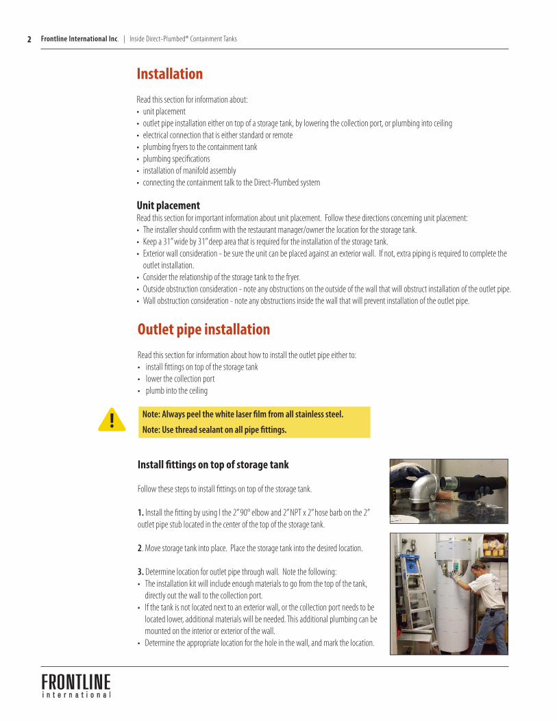
1. Install the fitting by using l the 2” 90° elbow and 2” NPT x 2” hose barb on the 2” outlet pipe stub located in the center of the top of the storage tank.
2. Move storage tank into place. Place the storage tank into the desired location.
3. Determine location for outlet pipe through wall. Note the following:• The installation kit will include enough materials to go from the top of the tank,
directly out the wall to the collection port.• If the tank is not located next to an exterior wall, or the collection port needs to be
located lower, additional materials will be needed. This additional plumbing can be mounted on the interior or exterior of the wall.
• Determine the appropriate location for the hole in the wall, and mark the location.
3Inside Direct-Plumbed® Containment Tanks | Frontline International Inc.
4. Move the storage tank out of the way, removing the storage tank from its location to allow clear access to the area.
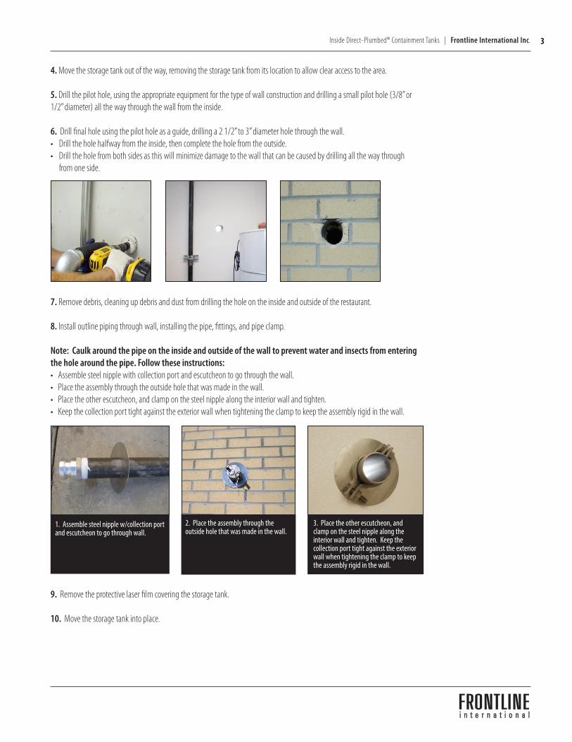
5. Drill the pilot hole, using the appropriate equipment for the type of wall construction and drilling a small pilot hole (3/8” or 1/2” diameter) all the way through the wall from the inside.
6. Drill final hole using the pilot hole as a guide, drilling a 2 1/2” to 3” diameter hole through the wall.• Drill the hole halfway from the inside, then complete the hole from the outside.• Drill the hole from both sides as this will minimize damage to the wall that can be caused by drilling all the way through
from one side.
7. Remove debris, cleaning up debris and dust from drilling the hole on the inside and outside of the restaurant.
8. Install outline piping through wall, installing the pipe, fittings, and pipe clamp.
Note: Caulk around the pipe on the inside and outside of the wall to prevent water and insects from entering the hole around the pipe. Follow these instructions:• Assemble steel nipple with collection port and escutcheon to go through the wall.• Place the assembly through the outside hole that was made in the wall.• Place the other escutcheon, and clamp on the steel nipple along the interior wall and tighten.• Keep the collection port tight against the exterior wall when tightening the clamp to keep the assembly rigid in the wall.
1. Assemble steel nipple w/collection port and escutcheon to go through wall.
2. Place the assembly through the outside hole that was made in the wall.
3. Place the other escutcheon, and clamp on the steel nipple along the interior wall and tighten. Keep the collection port tight against the exterior wall when tightening the clamp to keep the assembly rigid in the wall.
9. Remove the protective laser film covering the storage tank.
10. Move the storage tank into place.
4 Frontline International Inc. | Inside Direct-Plumbed® Containment Tanks
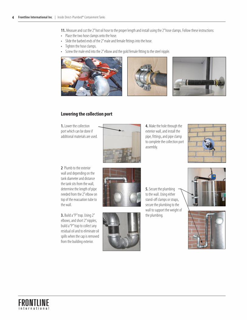
11. Measure and cut the 2” hot oil hose to the proper length and install using the 2” hose clamps. Follow these instructions:• Place the two hose clamps onto the hose.• Slide the barbed ends of the 2” male and female fittings into the hose.• Tighten the hose clamps.• Screw the male end into the 2” elbow and the gold female fitting to the steel nipple.
Lowering the collection port
1. Lower the collection port which can be done if additional materials are used.
2 Plumb to the exterior wall and depending on the tank diameter and distance the tank sits from the wall, determine the length of pipe needed from the 2” elbow on top of the evacuation tube to the wall.
3. Build a “P” trap. Using 2” elbows, and short 2” nipples, build a “P” trap to collect any residual oil and to eliminate oil spills when the cap is removed from the building exterior.
4. Make the hole through the exterior wall, and install the pipe, fittings, and pipe clamp to complete the collection port assembly.
5. Secure the plumbing to the wall. Using either stand-off clamps or straps, secure the plumbing to the wall to support the weight of the plumbing.
5Inside Direct-Plumbed® Containment Tanks | Frontline International Inc.
Plumb into ceiling
Follow these steps to plumb into the ceiling.
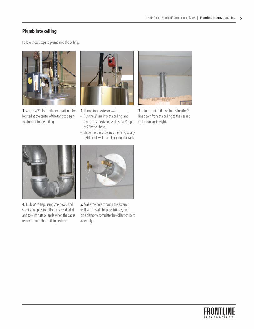
1. Attach a 2” pipe to the evacuation tube located at the center of the tank to begin to plumb into the ceiling.
2. Plumb to an exterior wall.• Run the 2” line into the ceiling, and
plumb to an exterior wall using 2” pipe or 2” hot oil hose.
• Slope this back towards the tank, so any residual oil will drain back into the tank.
3. Plumb out of the ceiling. Bring the 2” line down from the ceiling to the desired collection port height.
4. Build a “P” trap, using 2” elbows, and short 2” nipples to collect any residual oil and to eliminate oil spills when the cap is removed from the building exterior.
5. Make the hole through the exterior wall, and install the pipe, fittings, and pipe clamp to complete the collection port assembly.
6 Frontline International Inc. | Inside Direct-Plumbed® Containment Tanks
!
Electrical connectionRead this section for information about how to complete electrical connections as one of the following:• standard connection• remote connection
Standard electrical connectionComplete these steps to make a standard electrical connection:1. If the control panel is mounted to the tank, plug the storage tank into a 120v 15amp outlet.2. Be sure that the green power light comes on and remains lit. No other lights should be lit at this time.
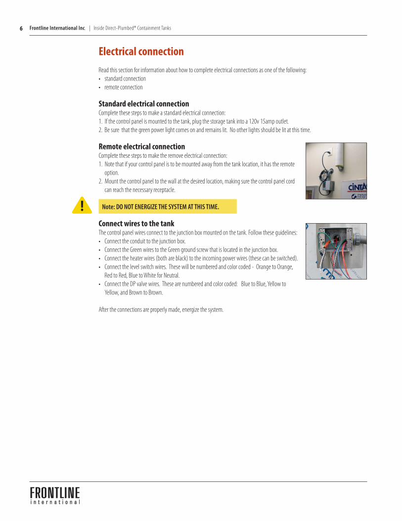
Remote electrical connectionComplete these steps to make the remove electrical connection:1. Note that if your control panel is to be mounted away from the tank location, it has the remote
option.2. Mount the control panel to the wall at the desired location, making sure the control panel cord
can reach the necessary receptacle.
Note: DO NOT ENERGIZE THE SYSTEM AT THIS TIME.
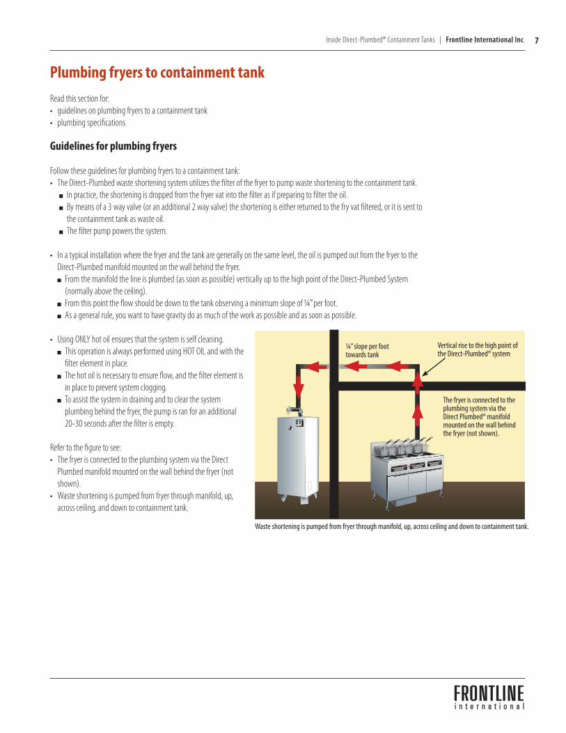
Connect wires to the tankThe control panel wires connect to the junction box mounted on the tank. Follow these guidelines: • Connect the conduit to the junction box.• Connect the Green wires to the Green ground screw that is located in the junction box.• Connect the heater wires (both are black) to the incoming power wires (these can be switched). • Connect the level switch wires. These will be numbered and color coded - Orange to Orange,
Red to Red, Blue to White for Neutral.• Connect the DP valve wires. These are numbered and color coded: Blue to Blue, Yellow to
Yellow, and Brown to Brown.
After the connections are properly made, energize the system.
7Inside Direct-Plumbed® Containment Tanks | Frontline International Inc.
Waste shortening is pumped from fryer through manifold, up, across ceiling and down to containment tank.
Plumbing fryers to containment tankRead this section for:• guidelines on plumbing fryers to a containment tank• plumbing specifications
Guidelines for plumbing fryers
Follow these guidelines for plumbing fryers to a containment tank:• The Direct-Plumbed waste shortening system utilizes the filter of the fryer to pump waste shortening to the containment tank.
In practice, the shortening is dropped from the fryer vat into the filter as if preparing to filter the oil. By means of a 3 way valve (or an additional 2 way valve) the shortening is either returned to the fry vat filtered, or it is sent to
the containment tank as waste oil. The filter pump powers the system.
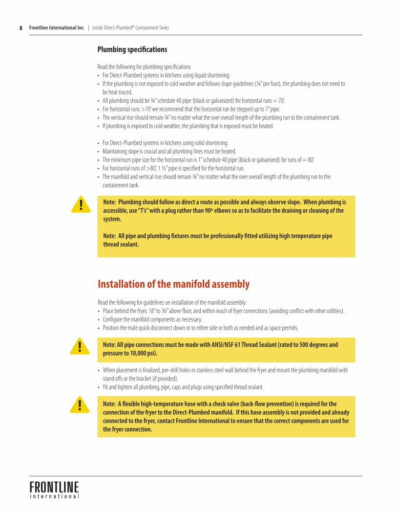
• In a typical installation where the fryer and the tank are generally on the same level, the oil is pumped out from the fryer to the Direct-Plumbed manifold mounted on the wall behind the fryer.
From the manifold the line is plumbed (as soon as possible) vertically up to the high point of the Direct-Plumbed System (normally above the ceiling).
From this point the flow should be down to the tank observing a minimum slope of ¼” per foot. As a general rule, you want to have gravity do as much of the work as possible and as soon as possible.
• Using ONLY hot oil ensures that the system is self cleaning. This operation is always performed using HOT OIL and with the
filter element in place. The hot oil is necessary to ensure flow, and the filter element is
in place to prevent system clogging. To assist the system in draining and to clear the system
plumbing behind the fryer, the pump is ran for an additional 20-30 seconds after the filter is empty.
Refer to the figure to see:• The fryer is connected to the plumbing system via the Direct
Plumbed manifold mounted on the wall behind the fryer (not shown).
• Waste shortening is pumped from fryer through manifold, up, across ceiling, and down to containment tank.
¼” slope per foot towards tank
Vertical rise to the high point of the Direct-Plumbed® system
The fryer is connected to the plumbing system via the Direct Plumbed® manifold mounted on the wall behind the fryer (not shown).
8 Frontline International Inc. | Inside Direct-Plumbed® Containment Tanks
!
Plumbing specifications
Read the following for plumbing specifications• For Direct-Plumbed systems in kitchens using liquid shortening:• If the plumbing is not exposed to cold weather and follows slope guidelines (¼” per foot), the plumbing does not need to
be heat traced. • All plumbing should be ¾” schedule 40 pipe (black or galvanized) for horizontal runs = 70’. • For horizontal runs >70’ we recommend that the horizontal run be stepped up to 1” pipe. • The vertical rise should remain ¾” no matter what the over overall length of the plumbing run to the containment tank. • If plumbing is exposed to cold weather, the plumbing that is exposed must be heated.
• For Direct-Plumbed systems in kitchens using solid shortening:• Maintaining slope is crucial and all plumbing lines must be heated. • The minimum pipe size for the horizontal run is 1” schedule 40 pipe (black or galvanized) for runs of = 80’. • For horizontal runs of >80’, 1 ½” pipe is specified for the horizontal run. • The manifold and vertical rise should remain ¾” no matter what the over overall length of the plumbing run to the
containment tank.
Note: Plumbing should follow as direct a route as possible and always observe slope. When plumbing is accessible, use “T’s” with a plug rather than 90º elbows so as to facilitate the draining or cleaning of the system.
Note: All pipe and plumbing fixtures must be professionally fitted utilizing high temperature pipe thread sealant.
Installation of the manifold assemblyRead the following for guidelines on installation of the manifold assembly:• Place behind the fryer, 18” to 36” above floor, and within reach of fryer connections (avoiding conflict with other utilities).• Configure the manifold components as necessary. • Position the male quick disconnect down or to either side or both as needed and as space permits.
Note: All pipe connections must be made with ANSI/NSF 61 Thread Sealant (rated to 500 degrees and pressure to 10,000 psi).
• When placement is finalized, pre-drill holes in stainless steel wall behind the fryer and mount the plumbing manifold with stand offs or the bracket (if provided).
• Fit and tighten all plumbing, pipe, caps and plugs using specified thread sealant.
Note: A flexible high-temperature hose with a check valve (back-flow prevention) is required for the connection of the fryer to the Direct-Plumbed manifold. If this hose assembly is not provided and already connected to the fryer, contact Frontline International to ensure that the correct components are used for the fryer connection.
!
!
9Inside Direct-Plumbed® Containment Tanks | Frontline International Inc.
!
!
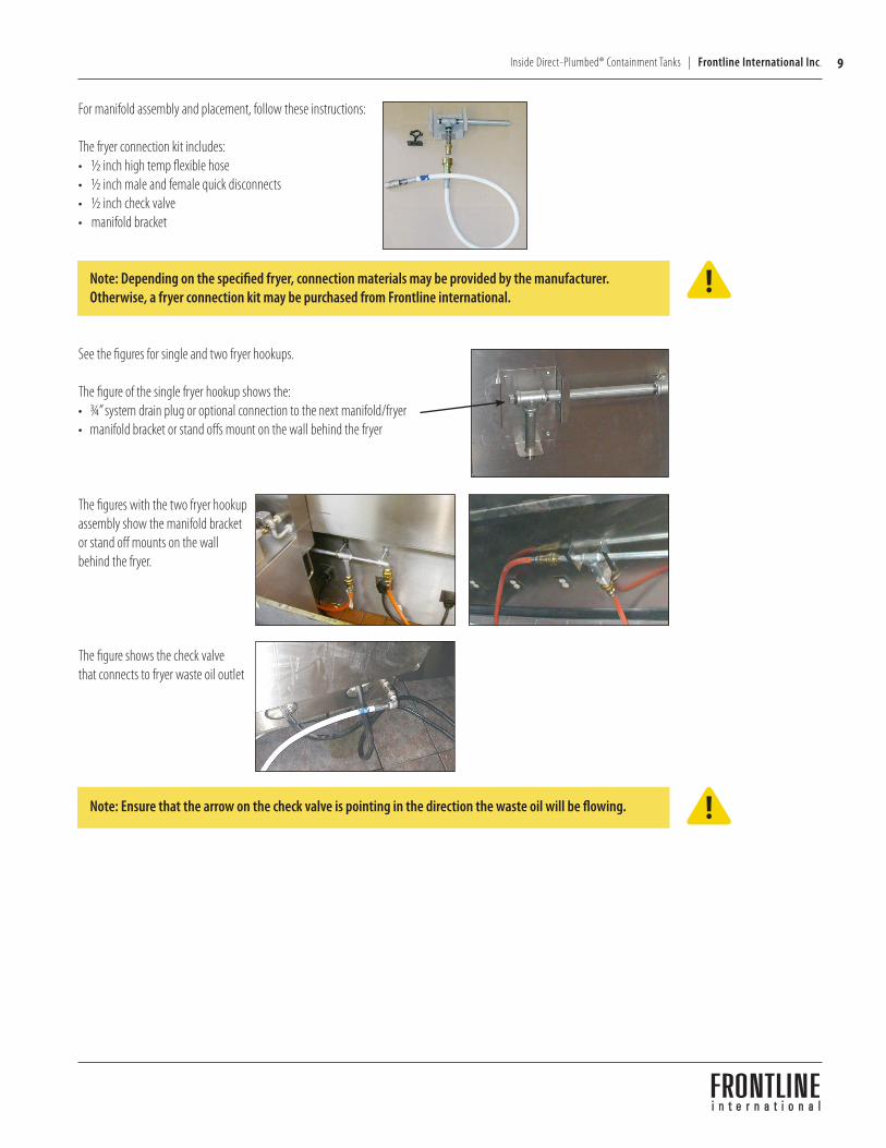
For manifold assembly and placement, follow these instructions:
The fryer connection kit includes:• ½ inch high temp flexible hose• ½ inch male and female quick disconnects• ½ inch check valve• manifold bracket
Note: Depending on the specified fryer, connection materials may be provided by the manufacturer. Otherwise, a fryer connection kit may be purchased from Frontline international.
See the figures for single and two fryer hookups.
The figure of the single fryer hookup shows the: • ¾” system drain plug or optional connection to the next manifold/fryer • manifold bracket or stand offs mount on the wall behind the fryer
The figures with the two fryer hookup assembly show the manifold bracket or stand off mounts on the wall behind the fryer.
The figure shows the check valve that connects to fryer waste oil outlet
Note: Ensure that the arrow on the check valve is pointing in the direction the waste oil will be flowing.
10 Frontline International Inc. | Inside Direct-Plumbed® Containment Tanks
!
!
!
!
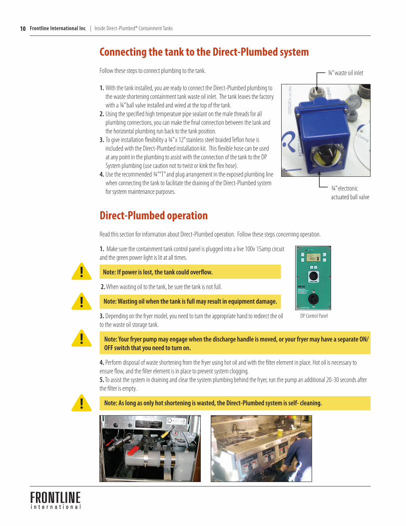
¾” waste oil inlet
Connecting the tank to the Direct-Plumbed systemFollow these steps to connect plumbing to the tank.
1. With the tank installed, you are ready to connect the Direct-Plumbed plumbing to the waste shortening containment tank waste oil inlet. The tank leaves the factory with a ¾” ball valve installed and wired at the top of the tank.
2. Using the specified high temperature pipe sealant on the male threads for all plumbing connections, you can make the final connection between the tank and the horizontal plumbing run back to the tank position.
3. To give installation flexibility a ¾” x 12” stainless steel braided Teflon hose is included with the Direct-Plumbed installation kit. This flexible hose can be used at any point in the plumbing to assist with the connection of the tank to the DP System plumbing (use caution not to twist or kink the flex hose).
4. Use the recommended ¾” “T” and plug arrangement in the exposed plumbing line when connecting the tank to facilitate the draining of the Direct-Plumbed system for system maintenance purposes. ¾” electronic
actuated ball valve
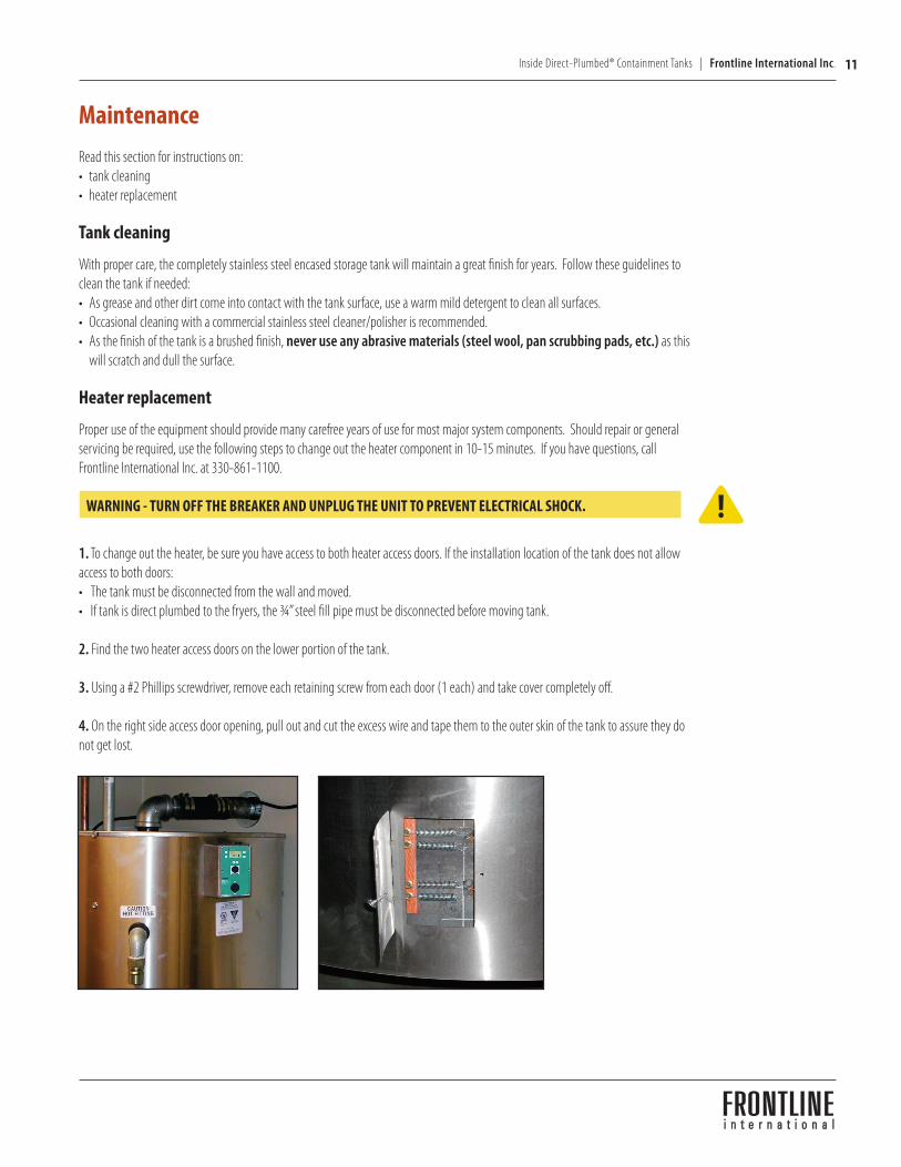
Direct-Plumbed operationRead this section for information about Direct-Plumbed operation. Follow these steps concerning operation.
1. Make sure the containment tank control panel is plugged into a live 100v 15amp circuit and the green power light is lit at all times.
Note: If power is lost, the tank could overflow.
2. When wasting oil to the tank, be sure the tank is not full.
Note: Wasting oil when the tank is full may result in equipment damage.
3. Depending on the fryer model, you need to turn the appropriate hand to redirect the oil to the waste oil storage tank.
Note: Your fryer pump may engage when the discharge handle is moved, or your fryer may have a separate ON/OFF switch that you need to turn on.
4. Perform disposal of waste shortening from the fryer using hot oil and with the filter element in place. Hot oil is necessary to ensure flow, and the filter element is in place to prevent system clogging.5. To assist the system in draining and clear the system plumbing behind the fryer, run the pump an additional 20-30 seconds after the filter is empty.
Note: As long as only hot shortening is wasted, the Direct-Plumbed system is self- cleaning.
DP Control Panel
11Inside Direct-Plumbed® Containment Tanks | Frontline International Inc.
Maintenance Read this section for instructions on:• tank cleaning• heater replacement
Tank cleaning
With proper care, the completely stainless steel encased storage tank will maintain a great finish for years. Follow these guidelines to clean the tank if needed:• As grease and other dirt come into contact with the tank surface, use a warm mild detergent to clean all surfaces.• Occasional cleaning with a commercial stainless steel cleaner/polisher is recommended.• As the finish of the tank is a brushed finish, never use any abrasive materials (steel wool, pan scrubbing pads, etc.) as this
will scratch and dull the surface.
Heater replacement Proper use of the equipment should provide many carefree years of use for most major system components. Should repair or general servicing be required, use the following steps to change out the heater component in 10-15 minutes. If you have questions, call Frontline International Inc. at 330-861-1100.
WARNING - TURN OFF THE BREAKER AND UNPLUG THE UNIT TO PREVENT ELECTRICAL SHOCK.
1. To change out the heater, be sure you have access to both heater access doors. If the installation location of the tank does not allow access to both doors:• The tank must be disconnected from the wall and moved.• If tank is direct plumbed to the fryers, the ¾” steel fill pipe must be disconnected before moving tank.
2. Find the two heater access doors on the lower portion of the tank. 3. Using a #2 Phillips screwdriver, remove each retaining screw from each door (1 each) and take cover completely off. 4. On the right side access door opening, pull out and cut the excess wire and tape them to the outer skin of the tank to assure they do not get lost.
!
12 Frontline International Inc. | Inside Direct-Plumbed® Containment Tanks
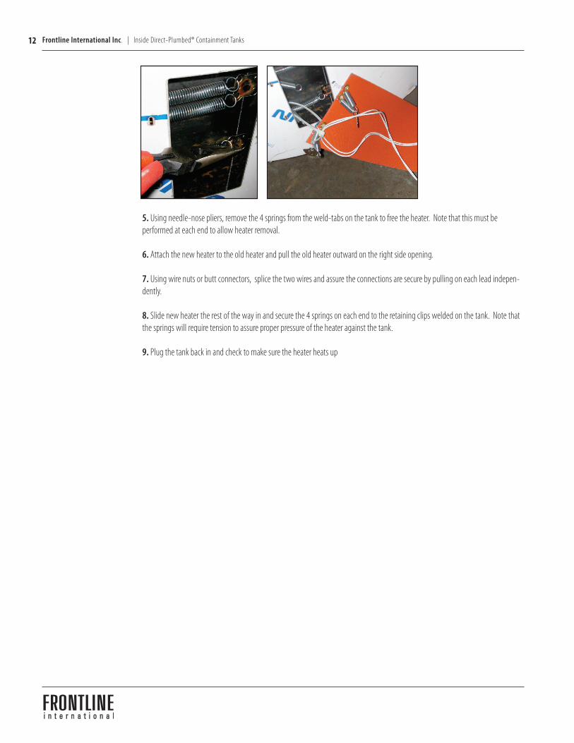
5. Using needle-nose pliers, remove the 4 springs from the weld-tabs on the tank to free the heater. Note that this must be performed at each end to allow heater removal. 6. Attach the new heater to the old heater and pull the old heater outward on the right side opening. 7. Using wire nuts or butt connectors, splice the two wires and assure the connections are secure by pulling on each lead indepen-dently. 8. Slide new heater the rest of the way in and secure the 4 springs on each end to the retaining clips welded on the tank. Note that the springs will require tension to assure proper pressure of the heater against the tank. 9. Plug the tank back in and check to make sure the heater heats up
13Inside Direct-Plumbed® Containment Tanks | Frontline International Inc.
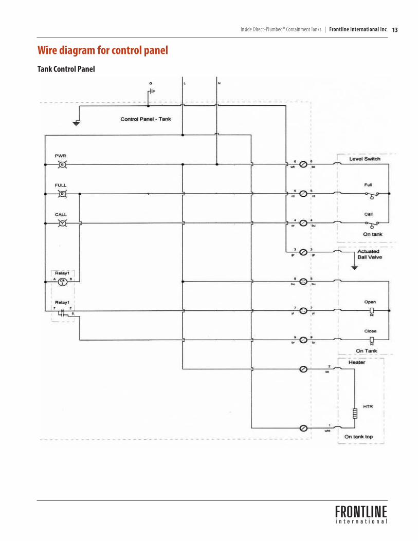
Wire diagram for control panel Tank Control Panel
Frontline International Inc.
Frontline International Inc. ● 95 16th Street SW ● Barberton, OH 44203 ● Phone: 330-861-1100 ● Fax: 330-861-1105
Tank Control Panel Model 70020012
Wire Diagram
14 Frontline International Inc. | Inside Direct-Plumbed® Containment Tanks
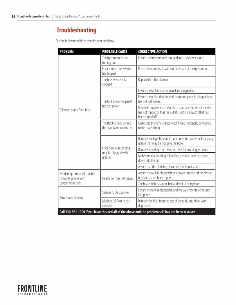
PROBLEM PROBABLE CAUSE CORRECTIVE ACTION
Oil won’t pump from filter
The fryer motor is not turning on.
Ensure the fryer motor is plugged into the power source.
Fryer motor reset switch has tripped.
Press the motor reset switch on the back of the fryer motor.
The filter element is clogged.
Replace the filter element.
The tank or control panel has lost power.
Ensure the tank or control panel are plugged in.
Ensure the outlet that the tank or control panel is plugged into has not lost power.
If there is no power to the outlet, make sure the circuit breaker has not tripped or that the outlet is not on a switch that has been turned off.
The flexible hose behind the fryer is not connected.
Make sure the female disconnect fitting is properly connected to the male fitting.
Fryer hose or plumbing may be plugged with grease.
Remove the fryer hose and run it under hot water to liquefy any grease that may be clogging the hose.
Remove any plugs from tees to check for any clogged lines.
Make sure that nothing is blocking the inlet tube that goes down into the oil.
Assure that the oil being discarded is in liquid state.
Rendering company is unable to empty grease from containment tank.
Heater belt has lost power.Assure the tank is plugged into a power outlet, and the circuit breaker has not been tripped.
The heater belt has gone bad and will need replaced.
Tank is overflowing.System has lost power. Ensure the tank is plugged in and the wall receptacle has not
lost power.
Mechanical float needs cleaned.
Remove the float from the top of the tank, and clean with degreaser.
Call 330-861-1100 if you have checked all of the above and the problem still has not been resolved.
TroubleshootingSee the following table to troubleshoot problems
15Inside Direct-Plumbed® Containment Tanks | Frontline International Inc.
WarrantyLimited Warranty for Frontline International, Inc. Appliances
Subject to the following conditions, Frontline International Inc. makes the following limited warranties to the original purchaser only for Frontline International appliances and replacement parts:
NEW EQUIPMENT: Any non-user part of a new appliance, except lamps, which proves to be defective in material or workmanship within one (1) year from date of original shipment, will be repaired or replaced without charge F.O.B. factory, Cuyahoga Falls, Ohio, or F.O.B. authorized distributor. Non-user parts on systems specifically include heater, level switch, and the control panel. Motors, pumps, and customer abuse will not be covered by this warranty.
REPLACEMENT PARTS: Any appliance part, except lamps, which proves to be defective in material or workmanship within ninety (90) days from the date of original installation, will be repaired or replaced without charge F.O.B. factory, Barberton, Ohio or F.O.B. authorized distributor.
This warranty for new equipment parts covers the repair or replacement of the defective part, and any labor charges for the removal and installation of any non-user part specified above. Replacement parts do not have any labor coverage.
Any claim must be represented to either Frontline International or the distributor from whom the appliance was purchased. No allowance will be granted for repairs made by anyone else without Frontline International’s written consent. If damage occurs during shipping, notify the sender at once so that a claim can be filed.
THE ABOVE LIMITED WARRANTY SETS FORTH THE SOLE REMEDY AGAINST FRONTLINE INTERNATIONAL FOR ANY BREACH OF WARRANTY OR OTHER TERM. BUYER AGREES THAT NO OTHER REMEDY (INCLUDING CLAIMS FOR ANY INCIDENTAL OR CONSEQUENTIAL DAMAGES) SHALL BE AVAILABLE.
The above warranty does not apply (a) to damage resulting from accident, alteration, misuse, or abuse; (b) to cold oil in storage tank due to main power being removed or unplugged from a system; (c) if the equipments serial number is removed or defaced; or (d) for lamps.
THE ABOVE LIMITED WARRANTY IS EXPRESSLY IN LIEU OF ALL OTHER WARRANTIES, EXPRESSED OR IMPLIED, INCLUDING MERCHANTABILITY AND FITNESS, AND ALL OTHER WARRANTIES ARE EXCLUDED. FRONTLINE INTERNATIONAL NEITHER ASSUMES NOR AUTHORIZES ANY PERSON TO ASSUME FOR IT ANY OTHER OBLIGATION OR LIABILITY.

16 Frontline International Inc. | Inside Direct-Plumbed® Containment Tanks