Embed Size (px)
Citation preview
Customer Service CenterDecatur, Illinois
800.423.1323www.muellercompany.com
Reliable ConnectionsTM
Improved,Centurion Series, ModernImproved,and 107®
Fire Hydrants Inserting Extension Sections
MUELLER®
i n s E R t i o n i n s t R U c t i o n s M a n U a L
table of ContentS PaGe Centurion Series Fire Hydrant – Adding an Extension 2-3
Improved Fire Hydrant – Inserting Extension Section (All Models Prior to 1962) 4-5
Improved Fire Hydrant – Inserting Extension Section (Sealed Oil Reservoir 1962 Style) 6-7
Improved Fire Hydrant – Inserting Extension Section with Steel Stem Coupling (Sealed Oil Reservoir 1962 Style) 8-9
Modern Improved Fire Hydrant – Inserting Extension Section 10-11 107® Fire Hydrant – Inserting Extension Section 12-13
Inserting Extension Sections – Notes 14-15
WARNING: before working on, or disassembling the Hydrant (including removing any bolts(s) holding the Hydrant together), shut off gate valve to isolate Hydrant from main water source. loosen (do not remove) one nozzle cap two turns and check for water under pressure inside Hydrant - bleed off any pressure, then remove nozzle cap completely. Open Hydrant main valve completely. A continuous flow of water, no matter how slight, indicates Hydrant is not properly isolated from the main water supply, and that problem must be corrected before any Hydrant disassembly can proceed. Disassembly of Hydrant with pressurized water acting against the main valve could result in unexpected ejection of Hydrant parts, debris or high-pressure water stream, which could cause serious bodily injury.
!
MUELLER® Centurion® Series Fire HydrantAdding an Extension
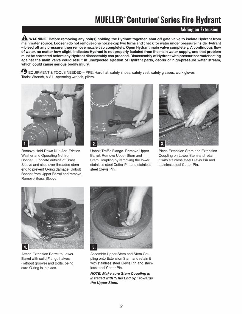
4.Attach Extension Barrel to Lower Barrel with solid Flange halves (without groove) and Bolts, being sure O-ring is in place.
WARNING: Before removing any bolt(s) holding the Hydrant together, shut off gate valve to isolate Hydrant from main water source. Loosen (do not remove) one nozzle cap two turns and check for water under pressure inside Hydrant – bleed off any pressure, then remove nozzle cap completely. Open Hydrant main valve completely. A continuous flow of water, no matter how slight, indicates Hydrant is not properly isolated from the main water supply, and that problem must be corrected before any Hydrant disassembly can proceed. Disassembly of Hydrant with pressurized water acting against the main valve could result in unexpected ejection of Hydrant parts, debris or high-pressure water stream, which could cause serious bodily injury.
2.Unbolt Traffic Flange. Remove Upper Barrel. Remove Upper Stem and Stem Coupling by removing the lower stainless steel Cotter Pin and stainless steel Clevis Pin.
Place Extension Stem and Extension Coupling on Lower Stem and retain it with stainless steel Clevis Pin and stainless steel Cotter Pin.
5.Assemble Upper Stem and Stem Cou-pling onto Extension Stem and retain it with stainless steel Clevis Pin and stain-less steel Cotter Pin. NOTE: Make sure Stem Coupling is installed with “This End Up” towards the Upper Stem.
1.Remove Hold-Down Nut, Anti-Friction Washer and Operating Nut from Bonnet. Lubricate outside of Brass Sleeve and slide over threaded stem end to prevent O-ring damage. Unbolt Bonnet from Upper Barrel and remove. Remove Brass Sleeve.
3.
!
2
EqUIPMENt & tOOLS NEEDED – PPE: Hard hat, safety shoes, safety vest, safety glasses, work gloves. tools: Wrench, A-311 operating wrench, pliers.
MUELLER® Centurion® Series Fire HydrantAdding an Extension
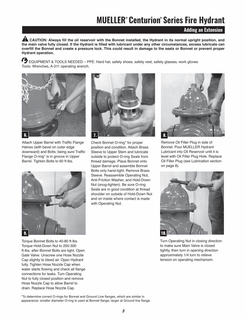
CAUTION: Always fill the oil reservoir with the Bonnet installed, the Hydrant in its normal upright position, and the main valve fully closed. If the Hydrant is filled with lubricant under any other circumstances, excess lubricate can overfill the Bonnet and create a pressure lock. This could result in damage to the seals or Bonnet or prevent proper Hydrant operation.
6.Attach Upper Barrel with Traffic Flange Halves (with bevel on outer edge downward) and Bolts; being sure Traffic Flange O-ring* is in groove in Upper Barrel. tighten Bolts to 60 ft-lbs.
8.
9.
Remove Oil Filler Plug in side of Bonnet. Pour MUELLER Hydrant Lubricant into Oil Reservoir until it is level with Oil Filler Plug Hole. Replace Oil Filler Plug (see Lubrication section on page 8).
torque Bonnet Bolts to 40-80 ft-lbs. torque Hold-Down Nut to 200-300 ft-lbs. after Bonnet Bolts are tight. Open Gate Valve. Unscrew one Hose Nozzle Cap slightly to bleed air. Open Hydrant fully. tighten Hose Nozzle Cap when water starts flowing and check all flange connections for leaks. turn Operating Nut to fully closed position and remove Hose Nozzle Cap to allow Barrel to drain. Replace Hose Nozzle Cap.
10.
7.
turn Operating Nut in closing direction to make sure Main Valve is closed tightly, then turn in opening direction approximately 1/4 turn to relieve tension on operating mechanism.
Check Bonnet O-ring* for proper position and condition. Attach Brass Sleeve to Upper Stem and lubricate outside to protect O-ring Seals from thread damage. Place Bonnet onto Upper Barrel and assemble Bonnet Bolts only hand-tight. Remove Brass Sleeve. Reassemble Operating Nut, Anti-Friction Washer, and Hold-Down Nut (snug-tighten). Be sure O-ring Seals are in good condition at thread shoulder on outside of Hold-Down Nut and on inside where contact is made with Operating Nut.
*To determine correct O-rings for Bonnet and Ground Line flanges, which are similar in appearance: smaller diameter O-ring is used at Bonnet flange; larger at Ground line flange.
!
3
EqUIPMENt & tOOLS NEEDED – PPE: Hard hat, safety shoes, safety vest, safety glasses, work gloves. tools: Wrenches, A-311 operating wrench.
MUELLER® Improved Fire HydrantInserting Extension Section (All Models Prior to 1962)
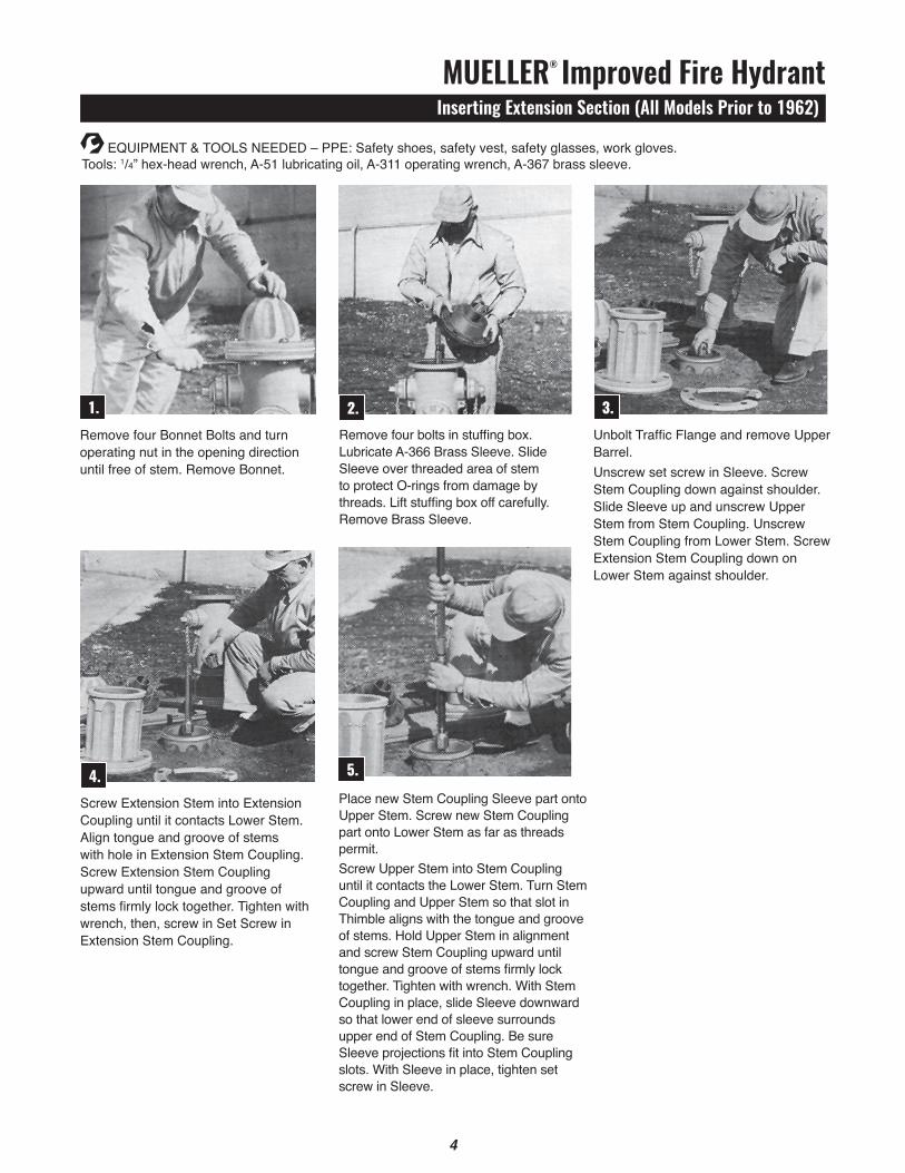
Remove four Bonnet Bolts and turnoperating nut in the opening directionuntil free of stem. Remove Bonnet.
Place new Stem Coupling Sleeve part onto Upper Stem. Screw new Stem Coupling part onto Lower Stem as far as threads permit. Screw Upper Stem into Stem Coupling until it contacts the Lower Stem. turn Stem Coupling and Upper Stem so that slot in thimble aligns with the tongue and groove of stems. Hold Upper Stem in alignment and screw Stem Coupling upward until tongue and groove of stems firmly lock together. tighten with wrench. With Stem Coupling in place, slide Sleeve downward so that lower end of sleeve surrounds upper end of Stem Coupling. Be sure Sleeve projections fit into Stem Coupling slots. With Sleeve in place, tighten set screw in Sleeve.
Remove four bolts in stuffing box. Lubricate A-366 Brass Sleeve. Slide Sleeve over threaded area of stem to protect O-rings from damage by threads. Lift stuffing box off carefully. Remove Brass Sleeve.
Unbolt Traffic Flange and remove Upper Barrel. Unscrew set screw in Sleeve. Screw Stem Coupling down against shoulder. Slide Sleeve up and unscrew Upper Stem from Stem Coupling. Unscrew Stem Coupling from Lower Stem. Screw Extension Stem Coupling down on Lower Stem against shoulder.
4
EqUIPMENt & tOOLS NEEDED – PPE: Safety shoes, safety vest, safety glasses, work gloves. tools: 1/4” hex-head wrench, A-51 lubricating oil, A-311 operating wrench, A-367 brass sleeve.
5
4.Screw Extension Stem into ExtensionCoupling until it contacts Lower Stem. Align tongue and groove of stems with hole in Extension Stem Coupling. Screw Extension Stem Coupling upward until tongue and groove of stems firmly lock together. Tighten with wrench, then, screw in Set Screw in Extension Stem Coupling.
2.1.
5.
3.
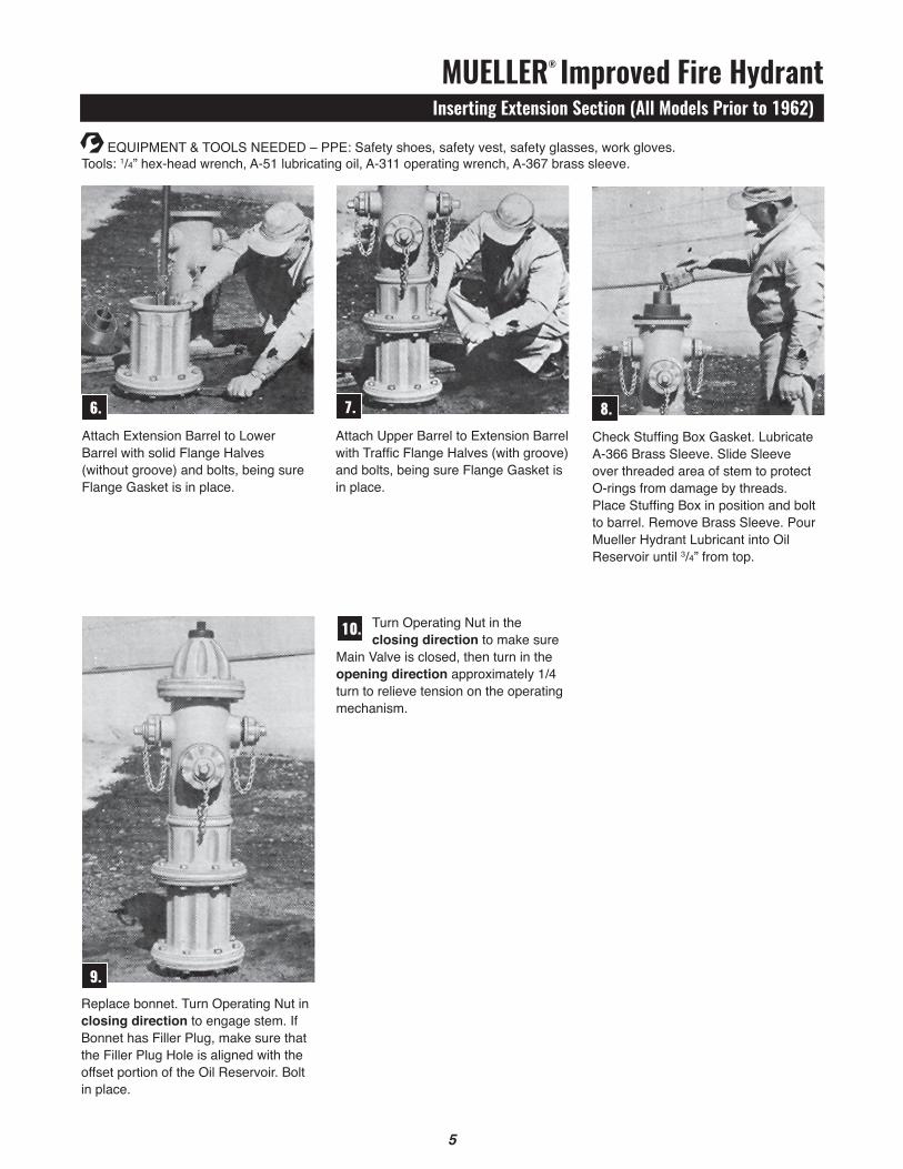
Attach Extension Barrel to Lower Barrel with solid Flange Halves (without groove) and bolts, being sure Flange Gasket is in place.
Attach Upper Barrel to Extension Barrel with Traffic Flange Halves (with groove) and bolts, being sure Flange Gasket is in place.
EqUIPMENt & tOOLS NEEDED – PPE: Safety shoes, safety vest, safety glasses, work gloves. tools: 1/4” hex-head wrench, A-51 lubricating oil, A-311 operating wrench, A-367 brass sleeve.
MUELLER® Improved Fire HydrantInserting Extension Section (All Models Prior to 1962)
5
6. 7.
Check Stuffing Box Gasket. Lubricate A-366 Brass Sleeve. Slide Sleeve over threaded area of stem to protect O-rings from damage by threads. Place Stuffing Box in position and bolt to barrel. Remove Brass Sleeve. Pour Mueller Hydrant Lubricant into Oil Reservoir until 3/4” from top.
Replace bonnet. turn Operating Nut in closing direction to engage stem. If Bonnet has Filler Plug, make sure that the Filler Plug Hole is aligned with the offset portion of the Oil Reservoir. Bolt in place.
8.
9.
turn Operating Nut in the closing direction to make sure
Main Valve is closed, then turn in the opening direction approximately 1/4 turn to relieve tension on the operating mechanism.
10.

MUELLER® Improved Fire HydrantInserting Extension Section (Sealed Oil Reservoir 1962 Style)
1. 3.Remove Weather Cap, Hold Down Nut and Operating Nut from Bonnet. Lubricate A-366 Brass Sleeve and slide over threaded stem end to prevent O-ring damage. Unbolt Bonnet from Upper Barrel and remove. Remove Brass Sleeve.
Screw Extension Stem into ExtensionCoupling until it contacts Lower Stem. Align tongue and groove of stems with hole in Extension Stem Coupling. Screw Extension Stem Coupling upward until tongue and groove of stems firmly lock together. Tighten with wrench, then screw in set screw in Extension Stem Coupling.
4.Place new Stem Coupling Sleeve part onto Upper Stem. Screw new Stem Coupling part onto Lower Stem as far as threads permit. Screw Upper Stem into Stem Coupling until it contacts the Lower Stem. turn Stem Coupling and Upper Stem so that slot in thimble aligns with the tongue and groove of stems. Hold Upper Stem in alignment and screw Stem Coupling upward until tongue and groove of stems firmly lock together. Tighten with wrench. With Stem Coupling in place, slide Sleeve downward so lower end of sleeve surrounds upper end of Stem Coupling. Be sure Sleeve projections fit into Stem Coupling slots. With Sleeve in place, tighten set screw in Sleeve.
Attach Extension Barrel to Lower Barrelwith solid Flange Halves (without groove) and bolts, being sure Flange Gasket is in place.
2.Unbolt Traffic Flange and remove Upper Barrel. Unscrew set screw in Sleeve. Screw Stem Coupling down against shoulder. Slide Sleeve up and unscrew Upper Stem from Stem Coupling. Unscrew Stem Coupling from Lower Stem. Screw Extension Stem Coupling down on Lower Stem against shoulder.
5.Attach Upper Barrel to Extension Barrel with Traffic Flange Halves (with groove) and bolts, being sure Flange Gasket is in place.
6
EqUIPMENt & tOOLS NEEDED – PPE: Hard hat, safety shoes, safety vest, safety glasses, work gloves. tools: Wrench, A-316 nozzle wrench, brass hammer.
6.

MUELLER® Improved Fire HydrantInserting Extension Section (Sealed Oil Reservoir 1962 Style)
EqUIPMENt & tOOLS NEEDED – PPE: Hard hat, safety shoes, safety vest, safety glasses, work gloves. tools: Wrench, A-367 brass sleeve, A-359 seat wrench, A-311 operating wrench.
Replace Hold Down Nut* being sure O-ring seals are in good condition at thread shoulder on outside of Hold Down Nut and on inside where contact is made with Operating Nut. Replace Weather Cap. tighten Bonnet Bolts. Check gasket tightness by opening one hose cap slightly before opening Hydrant to bleed air. Open Hydrant until barrel fills with water, tighten Hose Cap, open Hydrant fully. Check gaskets, and then turn Operating Nut to fully closed position.
*tighten hold down nut to 200-300 ft-lbs of torque. If torque wrench is not available, use a 3 lb hammer to strike the end of the A-311 wrench firmly two times to assure the nut is properly tightened.
Check Bonnet Gasket. Attach the A-24099 Brass Sleeve, if it had been removed, to Upper Stem and lubricate outside to protect O-ring seals from thread damage. Place Bonnet onto Upper Barrel and assemble Bonnet Bolts only hand tight. Remove Brass Sleeve. Reassemble Operating Nut and remove Oil Plug in side of Bonnet. Pour Mueller Hydrant Lubricant into Oil Reservoir until it is filled to the level of the Oil Plug. Replace Oil Plug.
turn Operating Nut in the closing direction to make sure
Main Valve is closed, then turn in the opening direction approximately 1/4 turn to relieve tension on the operating mechanism.
7
9.
7. 8.
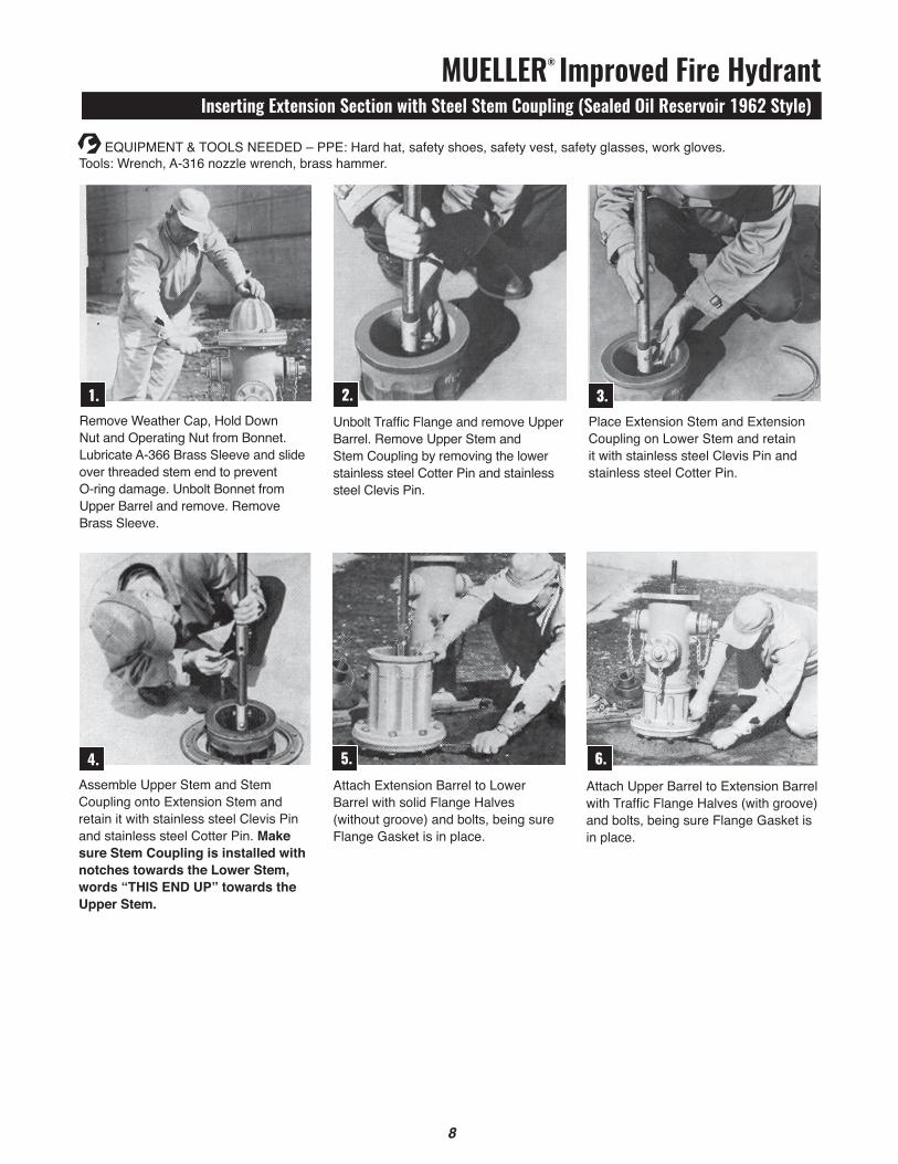
MUELLER® Improved Fire HydrantInserting Extension Section with Steel Stem Coupling (Sealed Oil Reservoir 1962 Style)
8
1. 3.Remove Weather Cap, Hold Down Nut and Operating Nut from Bonnet. Lubricate A-366 Brass Sleeve and slide over threaded stem end to prevent O-ring damage. Unbolt Bonnet from Upper Barrel and remove. Remove Brass Sleeve.
Place Extension Stem and ExtensionCoupling on Lower Stem and retain it with stainless steel Clevis Pin and stainless steel Cotter Pin.
4.Assemble Upper Stem and Stem Coupling onto Extension Stem and retain it with stainless steel Clevis Pin and stainless steel Cotter Pin. Make sure Stem Coupling is installed with notches towards the Lower Stem, words “tHIS END up” towards the upper Stem.
Attach Extension Barrel to Lower Barrel with solid Flange Halves (without groove) and bolts, being sure Flange Gasket is in place.
2.Unbolt Traffic Flange and remove UpperBarrel. Remove Upper Stem andStem Coupling by removing the lowerstainless steel Cotter Pin and stainless steel Clevis Pin.
5.Attach Upper Barrel to Extension Barrelwith Traffic Flange Halves (with groove) and bolts, being sure Flange Gasket is in place.
EqUIPMENt & tOOLS NEEDED – PPE: Hard hat, safety shoes, safety vest, safety glasses, work gloves. tools: Wrench, A-316 nozzle wrench, brass hammer.
6.

MUELLER® Improved Fire HydrantInserting Extension Section with Steel Stem Coupling (Sealed Oil Reservoir 1962 Style)
98
EqUIPMENt & tOOLS NEEDED – PPE: Hard hat, safety shoes, safety vest, safety glasses, work gloves. tools: Wrench, A-366 brass sleeve, A-359 seat wrench, A-311 operating wrench.
Replace Hold Down Nut* being sure O-ring seals are in good condition at thread shoulder on outside of Hold Down Nut and on inside where contact is made with Operating Nut. Replace Weather Cap. tighten Bonnet Bolts. Check gasket tightness by opening one hose cap slightly before opening Hydrant to bleed air. Open Hydrant until barrel fills with water, tighten Hose Cap, open Hydrant fully. Check gaskets, and then turn Operating Nut to full closed position.
*tighten hold down nut to 200-300 ft-lbs of torque. If torque wrench is not available, use a 3 lb hammer to strike the end of the A-311 wrench firmly two times to assure the nut is properly tightened.
Check Bonnet Gasket. Attach the A-366Brass Sleeve, if it had been removed, to Upper Stem and lubricate outside to protect O-ring seals from thread damage. Place Bonnet onto Upper Barrel and assemble Bonnet Bolts only hand tight. Remove Brass Sleeve. Reassemble Operating Nut and remove Oil Plug in side of Bonnet. Pour Mueller Hydrant Lubricant into Oil Reservoir until it is filled to the level of the Oil Plug. Replace Oil Plug.
turn Operating Nut in the closing direction to make sure
Main Valve is closed, then turn in the opening direction approximately 1/4 turn to relieve tension on the operating mechanism.
9.
7. 8.
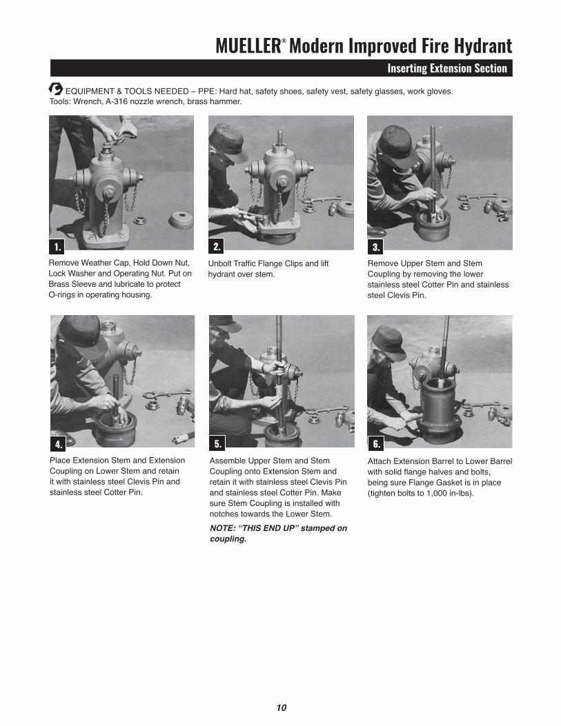
MUELLER® Modern Improved Fire HydrantInserting Extension Section
10
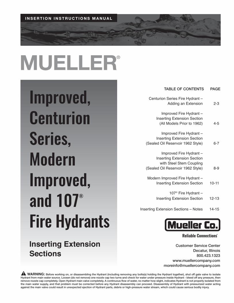
1. 3.Remove Weather Cap, Hold Down Nut, Lock Washer and Operating Nut. Put on Brass Sleeve and lubricate to protect O-rings in operating housing.
Remove Upper Stem and StemCoupling by removing the lower stainless steel Cotter Pin and stainless steel Clevis Pin.
4.Place Extension Stem and Extension Coupling on Lower Stem and retain it with stainless steel Clevis Pin and stainless steel Cotter Pin.
Assemble Upper Stem and Stem Coupling onto Extension Stem and retain it with stainless steel Clevis Pin and stainless steel Cotter Pin. Make sure Stem Coupling is installed with notches towards the Lower Stem. NOTE: “This ENd Up” stamped on coupling.
2.Unbolt Traffic Flange Clips and lift hydrant over stem.
5.Attach Extension Barrel to Lower Barrelwith solid flange halves and bolts, being sure Flange Gasket is in place (tighten bolts to 1,000 in-lbs).
EqUIPMENt & tOOLS NEEDED – PPE: Hard hat, safety shoes, safety vest, safety glasses, work gloves. tools: Wrench, A-316 nozzle wrench, brass hammer.
6.

MUELLER® Modern Improved Fire HydrantInserting Extension Section
11
7. 9.With lubricated Brass Sleeve on threads of Upper Stem and Upper Barrel Seal in position, lift Upper Barrel over Upper Stem and onto extension section Attach Traffic Flange Clips and Traffic Flange Clip Bolts loosely, face nozzles in desired position and tighten Traffic Flange Clip Bolts uniformly to 1,000 in-lbs.
tighten Hold Down Nut to 100 ft-lbs and bend Lock Washer Ears over Hold Down Nut flats in two places and over Operating Housing in two places.
10.Remove Oil Filler Plug and add Mueller® Hydrant Lubricant until level with Filler Plug hole. Replace Oil Filler Plug and replace Weather Cap.
8.With extension section and Hydrantsecurely bolted in place, remove BrassSleeve, replace Operating Nut, Lock Washer, and Hold Down Nut.
EqUIPMENt & tOOLS NEEDED – PPE: Hard hat, safety shoes, safety vest, safety glasses, work gloves. tools: Wrench, A-316 nozzle wrench, brass hammer.
Open Hydrant fully and loosen one Hose Nozzle Cap, to bleed
air. When barrel is filled with water, tighten Nozzle Cap and check gaskets. turn Operating Nut to fully closed position, loosen one nozzle cap to allow barrel to drain.
11. turn Operating Nut in the closing direction to make sure
Main Valve is closed, then turn in the opening direction approximately 1/4 turn to relieve tension on the operating mechanism.
12.
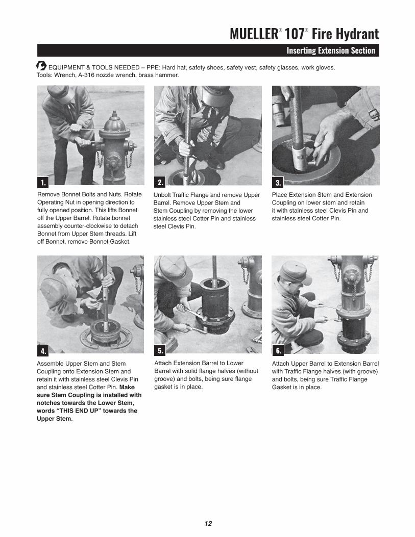
MUELLER® 107® Fire HydrantInserting Extension Section
12
1. 3.Remove Bonnet Bolts and Nuts. Rotate Operating Nut in opening direction to fully opened position. this lifts Bonnet off the Upper Barrel. Rotate bonnet assembly counter-clockwise to detach Bonnet from Upper Stem threads. Lift off Bonnet, remove Bonnet Gasket.
Place Extension Stem and ExtensionCoupling on lower stem and retain it with stainless steel Clevis Pin and stainless steel Cotter Pin.
4.Assemble Upper Stem and Stem Coupling onto Extension Stem and retain it with stainless steel Clevis Pin and stainless steel Cotter Pin. Make sure Stem Coupling is installed with notches towards the Lower Stem, words “tHIS END up” towards the upper Stem.
Attach Extension Barrel to Lower Barrel with solid flange halves (without groove) and bolts, being sure flange gasket is in place.
2.Unbolt Traffic Flange and remove UpperBarrel. Remove Upper Stem andStem Coupling by removing the lowerstainless steel Cotter Pin and stainless steel Clevis Pin.
5.Attach Upper Barrel to Extension Barrelwith Traffic Flange halves (with groove) and bolts, being sure Traffic Flange Gasket is in place.
EqUIPMENt & tOOLS NEEDED – PPE: Hard hat, safety shoes, safety vest, safety glasses, work gloves. tools: Wrench, A-316 nozzle wrench, brass hammer.
6.
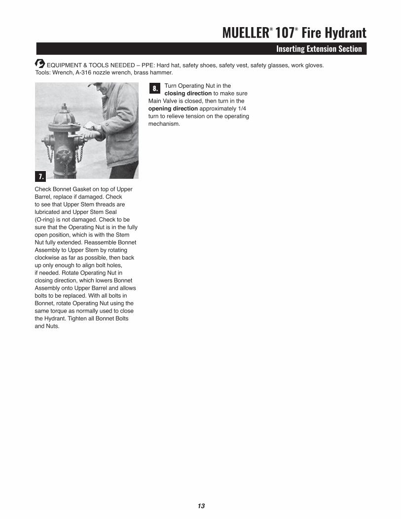
MUELLER® 107® Fire HydrantInserting Extension Section
13
7.Check Bonnet Gasket on top of Upper Barrel, replace if damaged. Check to see that Upper Stem threads are lubricated and Upper Stem Seal (O-ring) is not damaged. Check to be sure that the Operating Nut is in the fully open position, which is with the Stem Nut fully extended. Reassemble Bonnet Assembly to Upper Stem by rotating clockwise as far as possible, then back up only enough to align bolt holes, if needed. Rotate Operating Nut in closing direction, which lowers Bonnet Assembly onto Upper Barrel and allows bolts to be replaced. With all bolts in Bonnet, rotate Operating Nut using the same torque as normally used to close the Hydrant. tighten all Bonnet Bolts and Nuts.
EqUIPMENt & tOOLS NEEDED – PPE: Hard hat, safety shoes, safety vest, safety glasses, work gloves. tools: Wrench, A-316 nozzle wrench, brass hammer.
turn Operating Nut in the closing direction to make sure
Main Valve is closed, then turn in the opening direction approximately 1/4 turn to relieve tension on the operating mechanism.
8.

Inserting Extension SectionsNotes
14

Inserting Extension SectionNotes
15

Water (U.S.)[email protected]
Form 10923 - Rev 09/17
Copyright © 2016 Mueller Co., LLC. All Rights Reserved.The trademarks, logos and service marks displayed in this document herein are the property of Mueller Co., LLC, its affiliates or other third parties. Products marked with a section symbol ( § ) are subject to patents or patent applications. For details, visit www.mwppat.com. these products are intended for use in potable water applications. Please contact your Mueller Sales or Customer Service Representative concerning any other application(s).
Reliable ConnectionsTM
Water (Canada)[email protected]
International1.423.490.9555www.mueller-international.cominternational@muellercompany.com