Embed Size (px)
Citation preview

INSTALLATION AND USER MANUAL EN
INSERT
FRESIA 70 AIR 9 S1PART 2 - OPERATION AND CLEANING
Instructions in English

II
TABLE OF CONTENTS
TABLE OF CONTENTS .................................................................................................. II14-FIRST IGNITION .....................................................................................................315-CONTROL PANEL ....................................................................................................516-MENU ITEMS AND OPERATION ................................................................................617-SAFETY DEVICES ..................................................................................................1418-ALARMS ..............................................................................................................1519-RECOMMENDATIONS FOR SAFE USE .......................................................................2020-CLEANING ...........................................................................................................2121-FAULTS/CAUSES/SOLUTIONS .................................................................................3022-CIRCUIT BOARD ...................................................................................................33

1
3
14-FIRST IGNITION
Technical Dept. - All rights reserved - Reproduction prohibited
WARNINGS BEFORE IGNITIONGENERAL WARNINGSRemove any objects that may burn from the brazier (manual, various adhesive labels or any polystyrene).Check that the brazier is positioned correctly and rests properly on the base.
The first ignition may not be successful as the feed screw is empty and does not always manage to load the brazier with the required amount of pellets in time to light the flame.
CANCEL THE FAILED IGNITION ALARM BY PRESSING AND HOLDING THE ON/OFF KEY FOR A FEW SECONDS. REMOVE THE PELLETS LEFT IN THE BRAZIER AND REPEAT THE IGNITION.
SETTINGS TO BE CARRIED OUT BEFORE THE INITIAL START-UP/SHUTDOWNIgnitionAfter connecting the power cable to the back of the product, turn the switch at the back to position(I). To turn the stove on or off, press button 1 on the control panel.The display on the panel will be ON with a flashing flame. When the flame stops blinking, the stove has reached the operating condition to “supply power”.The default factory set room temperature is 20°C. To change this setting, follow the instructions in the adjustments menu. Do the same to set the heating water temperature and the speed of the ventilation fan (if required). To activate an external thermostat, if present, see the dedicated paragraph.
SWITCHING THE EQUIPMENT OFFTo switch the equipment off, press the key 1 on the panel.The equipment will start the shutdown process which involves consuming the residual pellets in the brazier, the latter being cleaned and the residual heat in the structure being disposed of.During the disposal phase of the residual heat, the fans operate at about 80% of their output and the speed cannot be varied. This is determined by the need for all the accumulated heat to be evacuated safely and quickly. The shutdown stage can last 15 - 30 minutes depending on the heat stored in the structure, determined by the duration and the operating speed of the product throughout the day.When the internal temperature drops below the set thresholds, the hot air and exhaust fume extraction fans will automatically switch off.

4
14-FIRST IGNITION
POWER SUPPLYWhen ignition is complete, the panel will display ON with a constant flame at level 3 . The following flame modulation for higher or lower power is then controlled autonomously based on reaching the set temperature.(also see “OPERATING MODE” - “Set Flame”)
If the flame fails to ignite, despite a regular flow of pellets, check that the brazier is seated correctly: it must rest snugly against the interlocking slot and be clean of any ash incrustations. If no anomaly is found during this inspection, there may be a problem with the product components or installation may not be correct.
REMOVE THE PELLETS FROM THE BRAZIER AND CONTACT AN AUTHORISED TECHNICIAN.Please ensure the brazier is clear of ALL pellets and ash build up following any failed ignitions. Failure to clear out the brazier prior to resetting may result in further failed ignitions or explosive ignition under certain conditions.
It is good practice to ensure effective ventilation in the room during the initial ignition, as the product will emit some smoke and smell of paint.
Do not stand close to the product and ventilate the room as mentioned. The smell of paint will disappear after about an hour of operation, however, it is not harmful in any case.The product will be subject to expansion and contraction during the ignition and cooling stages, therefore slight creaking noises may be heard.This is absolutely normal as the structure is made of laminated steel and must not be considered a defect.
DO NOT EXPECT HEATING EFFICIENCY IMMEDIATELY!!! THE PRODUCT NEEDS SOME RUNNING-IN TIME.
It is extremely important to make sure the product does not reach high temperatures straight away, but to increase the temperature gradually using low power at first.This will prevent damage to the welds and to the steel structure.
Do not touch the product during the first lighting, as it is during this stage that the paint sets. If you touch the paint, you may expose the steel surface.
If required, touch up the paint with the spray can of the specific colour.
7 2 3 4
61 5
5
15-CONTROL PANEL
Technical Dept. - All rights reserved - Reproduction prohibited
KEY
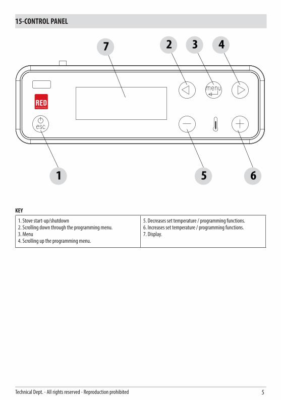
1. Stove start-up/shutdown2. Scrolling down through the programming menu.3. Menu4. Scrolling up the programming menu.
5. Decreases set temperature / programming functions.6. Increases set temperature / programming functions.7. Display.
6
16-MENU ITEMS AND OPERATION
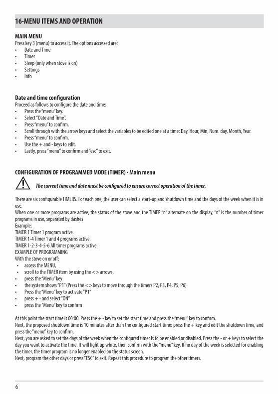
MAIN MENUPress key 3 (menu) to access it. The options accessed are:• Date and Time• Timer• Sleep (only when stove is on)• Settings• Info
Date and time configurationProceed as follows to configure the date and time:• Press the “menu” key.• Select “Date and Time”.• Press “menu” to confirm.• Scroll through with the arrow keys and select the variables to be edited one at a time: Day, Hour, Min, Num. day, Month, Year.• Press “menu” to confirm.• Use the + and - keys to edit.• Lastly, press “menu” to confirm and “esc” to exit.
CONFIGURATION OF PROGRAMMED MODE (TIMER) - Main menu
The current time and date must be configured to ensure correct operation of the timer.
There are six configurable TIMERS. For each one, the user can select a start-up and shutdown time and the days of the week when it is in use.When one or more programs are active, the status of the stove and the TIMER “n” alternate on the display, “n” is the number of timer programs in use, separated by dashes Example: TIMER 1 Timer 1 program active.TIMER 1-4 Timer 1 and 4 programs active.TIMER 1-2-3-4-5-6 All timer programs active.EXAMPLE OF PROGRAMMINGWith the stove on or off:• access the MENU, • scroll to the TIMER item by using the <> arrows,• press the “Menu” key• the system shows “P1” (Press the <> keys to move through the timers P2, P3, P4, P5, P6)• Press the “Menu” key to activate “P1”• press + - and select “ON”• press the “Menu” key to confirm
At this point the start time is 00:00. Press the + - key to set the start time and press the “menu” key to confirm.Next, the proposed shutdown time is 10 minutes after than the configured start time: press the + key and edit the shutdown time, and press the “menu” key to confirm.Next, you are asked to set the days of the week when the configured timer is to be enabled or disabled. Press the - or + keys to select the day you want to activate the time. It will light up white, then confirm with the “menu” key. If no day of the week is selected for enabling the timer, the timer program is no longer enabled on the status screen.Next, program the other days or press “ESC” to exit. Repeat this procedure to program the other timers.

7
16-MENU ITEMS AND OPERATION
Technical Dept. - All rights reserved - Reproduction prohibited
EXAMPLES OF PROGRAMMING:
P1 P2
on off day on off day
08:00 12:00 mon 11:00 14:00 mon
Stove on between 08:00 and 14:00
P1 P2
on off day on off day
08:00 11:00 mon 11:00 14:00 mon
Stove on between 08:00 and 14:00
P1 P2
on off day on off day
17:00 24:00 mon 00:00 06:00 tue
Stove on between 17:00 on Monday to 06:00 on Tuesday
NOTES ON USE OF THE TIMER• The timer start always occurs with the last temperature and ventilation settings (or with the default settings at 20°C and V3 if they
have never been altered).• The start-up time goes from 00:00 to 23:50• If the shutdown time has not yet been saved, the program proposes a start-up time at +10 minutes.• If a timer program turns off the stove at 24:00 on one day and another program starts it up at 00:00 on the next day: the stove
remains on.• A program proposes a start-up and/or shutdown time that overlap the times of another program: if the stove is already on, the start
has no effect while OFF turns off the stove.• When the stove is on and the timer is active, pressing the OFF key turns off the stove. The stove then restarts automatically at the
next time of the timer.• When the stove is off and the timer is active, pressing the ON key turns on the stove. The stove then stops automatically at the next
time of the timer.
SLEEP FUNCTION (main menu)Sleep may only be activated when the stove is on and allows you to quickly set a time for the product to turn off. To set the Sleep function, proceed as follows:• Enter the MENU • Scroll to the SLEEP item with the <> arrows• Press Menu• Set the desired shutdown time by using the + and - keys.The panel shows a shutdown time of 10 minutes after the current time, which can be adjusted with key 6 up to the following day (i.e. the shutdown can be delayed up to a maximum of 23 hours and 50 minutes).If the SLEEP function is active with the TIMER active, the former has priority, therefore the stove will not turn off at the time set in the timer program but at the time set by the sleep function, even if it comes after the time set by the timer.

P5 P1
8
16-MENU ITEMS AND OPERATION
OPERATING MODEADJUSTMENT MENU“Adjustments” menu settings determine the operating mode of the stove.To access the menu, proceed as follows:• Press the + - keys• Scroll by using the <> arrows and select “Set Amb. T” or “Set Ventilation T” or “Set Flame”• Press “menu” to enter the option selected.• Change by using the + - keys.• Press “menu” to confirm and “esc” to exit.
Set Amb T - this function is used to set the temperature to be reached in the room in which the stove is installed, from a minimum of 5°C to a maximum of 35°C. When this condition is met, the stove setting is equivalent to the minimum consumption values (the flame and hot air fan speed at minimum), and then returns to the set values when the room temperature drops below the set threshold.N.B: The point to the right of the room temperature on the control panel display indicates the half degrees (e.g. 23.°C is equivalent to 23.5°C).
Set Vent - this function allows you to select the desired speed of the room fan from 1 to 5.
Set Flame - this function allows you to set the power of the flame from a minimum of 1 to a maximum of 5. The power levels correspond to a different value of fuel consumption, setting 5 heats the room in less time and setting 1 can keep the room temperature stable for a longer period of time. The set flame is automatically set to a minimum when the set temperature value is reached.
DISPLAY WITH STOVE ONif the bars are all full, the stove is on flame power 5if only one bar is full, the stove is on flame power 1if the bars are flashing, automatic cleaning is in progress
9
16-MENU ITEMS AND OPERATION
Technical Dept. - All rights reserved - Reproduction prohibited
SETTINGS MENUThe SETTINGS menu enables to configure the stove operating modes:a. Language.b. Cleaning (only displayed when stove is off).c. Feed screw loading (shown only when stove is off).d. Tones.e. External thermostat (activation).f. Auto Eco (activation).g. Eco Turn-off T (default 10 minutes).h. Pellet recipe.i. Smoke rpm % var.j. Component test (only displayed when the stove is off).k. “Chimney sweeper” function (can only be enabled when stove is on, to check emissions in field).l. Technical menu.
a - LanguageProceed as follows to select the language:• Press the “menu” key.• Use the arrow keys to scroll through and select “Settings”• Press “menu” to confirm.• Use the arrow keys to scroll through and select “language”.• Press “menu” to confirm.• Use the + - keys to select the required language (IT/EN/DE/FR/ES/NL/PL/DK/SLO)• Press “menu” to confirm and “esc” to exit.
b - CleaningProceed as follows to select “Cleaning” (only with stove off):• Press the “menu” key.• Use the arrow keys to scroll through and select “Settings”• Press “menu” to confirm.• Use the arrow keys to scroll through and select ‘’Cleaning’’• Press “menu” to confirm.• Use the + - keys to select “On”.• Press “esc” to exit.
c - Feed screw loadingTo select ‘’Feed screw loading’’ (only with stove off), proceed as follows:• Press the “menu” key.• Use the arrow keys to scroll through and select “Settings”• Press “menu” to confirm.• Scroll with the arrows and select “Feed screw loading”.• Press “menu” to confirm.• With the + key “Enable” feed screw loading.• Press “esc” to exit.
10
16-MENU ITEMS AND OPERATION
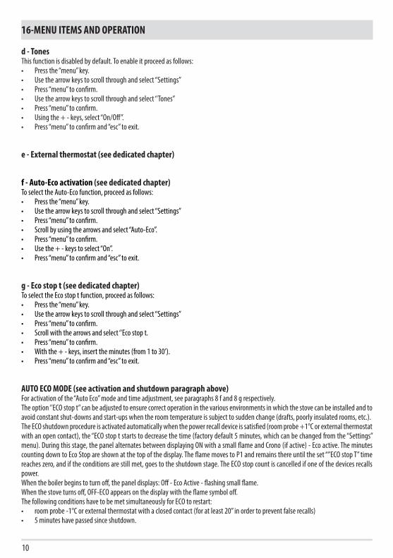
d - TonesThis function is disabled by default. To enable it proceed as follows:• Press the “menu” key.• Use the arrow keys to scroll through and select “Settings”• Press “menu” to confirm.• Use the arrow keys to scroll through and select ‘’Tones’’• Press “menu” to confirm.• Using the + - keys, select “On/Off”.• Press “menu” to confirm and “esc” to exit.
e - External thermostat (see dedicated chapter)
f - Auto-Eco activation (see dedicated chapter)To select the Auto-Eco function, proceed as follows:• Press the “menu” key.• Use the arrow keys to scroll through and select “Settings”• Press “menu” to confirm.• Scroll by using the arrows and select “Auto-Eco”.• Press “menu” to confirm.• Use the + - keys to select “On”.• Press “menu” to confirm and “esc” to exit.
g - Eco stop t (see dedicated chapter)To select the Eco stop t function, proceed as follows:• Press the “menu” key.• Use the arrow keys to scroll through and select “Settings”• Press “menu” to confirm.• Scroll with the arrows and select ‘’Eco stop t.• Press “menu” to confirm.• With the + - keys, insert the minutes (from 1 to 30’).• Press “menu” to confirm and “esc” to exit.
AUTO ECO MODE (see activation and shutdown paragraph above)For activation of the “Auto Eco” mode and time adjustment, see paragraphs 8 f and 8 g respectively.The option ‘’ECO stop t” can be adjusted to ensure correct operation in the various environments in which the stove can be installed and to avoid constant shut-downs and start-ups when the room temperature is subject to sudden change (drafts, poorly insulated rooms, etc.).The ECO shutdown procedure is activated automatically when the power recall device is satisfied (room probe +1°C or external thermostat with an open contact), the “ECO stop t starts to decrease the time (factory default 5 minutes, which can be changed from the “Settings” menu). During this stage, the panel alternates between displaying ON with a small flame and Crono (if active) - Eco active. The minutes counting down to Eco Stop are shown at the top of the display. The flame moves to P1 and remains there until the set “”ECO stop T” time reaches zero, and if the conditions are still met, goes to the shutdown stage. The ECO stop count is cancelled if one of the devices recalls power.When the boiler begins to turn off, the panel displays: Off - Eco Active - flashing small flame.When the stove turns off, OFF-ECO appears on the display with the flame symbol off.The following conditions have to be met simultaneously for ECO to restart:• room probe -1°C or external thermostat with a closed contact (for at least 20” in order to prevent false recalls)• 5 minutes have passed since shutdown.
11
16-MENU ITEMS AND OPERATION
Technical Dept. - All rights reserved - Reproduction prohibited
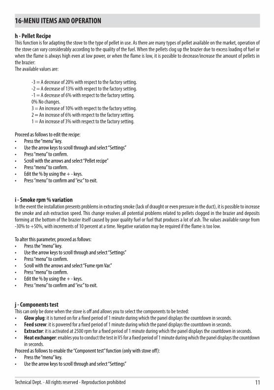
h - Pellet RecipeThis function is for adapting the stove to the type of pellet in use. As there are many types of pellet available on the market, operation of the stove can vary considerably according to the quality of the fuel. When the pellets clog up the brazier due to excess loading of fuel or when the flame is always high even at low power, or when the flame is low, it is possible to decrease/increase the amount of pellets in the brazier:The available values are:
-3 = A decrease of 20% with respect to the factory setting.-2 = A decrease of 13% with respect to the factory setting.-1 = A decrease of 6% with respect to the factory setting.0% No changes.3 = An increase of 10% with respect to the factory setting.2 = An increase of 6% with respect to the factory setting.1 = An increase of 3% with respect to the factory setting.
Proceed as follows to edit the recipe:• Press the “menu” key.• Use the arrow keys to scroll through and select “Settings”• Press “menu” to confirm.• Scroll with the arrows and select “Pellet recipe’’• Press “menu” to confirm.• Edit the % by using the + - keys.• Press ‘’menu’’ to confirm and ‘’esc’’ to exit.
i - Smoke rpm % variationIn the event the installation presents problems in extracting smoke (lack of draught or even pressure in the duct), it is possible to increase the smoke and ash extraction speed. This change resolves all potential problems related to pellets clogged in the brazier and deposits forming at the bottom of the brazier itself caused by poor quality fuel or fuel that produces a lot of ash. The values available range from -30% to +50%, with increments of 10 percent at a time. Negative variation may be required if the flame is too low.
To alter this parameter, proceed as follows:• Press the “menu” key.• Use the arrow keys to scroll through and select “Settings”• Press “menu” to confirm.• Scroll with the arrows and select “Fume rpm Var.”• Press “menu” to confirm.• Edit the % by using the + - keys.• Press ‘’menu’’ to confirm and ‘’esc’’ to exit.
j - Components testThis can only be done when the stove is off and allows you to select the components to be tested:• Glow plug: it is turned on for a fixed period of 1 minute during which the panel displays the countdown in seconds.• Feed screw: it is powered for a fixed period of 1 minute during which the panel displays the countdown in seconds.• Extractor: it is activated at 2500 rpm for a fixed period of 1 minute during which the panel displays the countdown in seconds.• Heat exchanger: enables you to conduct the test in V5 for a fixed period of 1 minute during which the panel displays the countdown
in seconds.Proceed as follows to enable the “Component test” function (only with stove off):• Press the “menu” key.• Use the arrow keys to scroll through and select “Settings”

12
16-MENU ITEMS AND OPERATION
• Press “menu” to confirm.• Use the arrow keys to scroll through and select ‘’Component test’’• Press “menu” to confirm.• Use the + - keys to select the test to be carried out.• Press ‘’menu’’ to confirm and ‘’esc’’ to exit.
k - Chimney sweeper function (for maintenance operators only) - This function can only be activated when the stove is on and power is supplied, and it forces heating operation at parameters P5, with the ventilator (if present) in V5. Any corrections to the loading/smoke ventilation percentage must be read. This state lasts 20 minutes, the countdown is displayed on the panel. The technician can stop this stage at any moment by quickly pressing the on/off key.Proceed as follows to enable the “Chimney sweeper”:• Press the “menu” key.• Use the arrow keys to scroll through and select “Settings”• Press “menu” to confirm.• Use the arrow keys to scroll through and select ‘’Chimney sweeper function’’• Press “menu” to confirm.• Use the + - keys to select “On” (Off by default)• Press ‘’menu’’ to confirm and ‘’esc’’ to exit.
l - Technical menuTo access the technical menu you must contact the support centre as it requires a password.Proceed as follows to access the “technical menu”:• Press the “menu” key.• Use the arrow keys to scroll through and select “Settings”• Press “menu” to confirm.• Use the arrow keys to scroll through and select ‘’Technical menu’’• Press “menu” to confirm.• With the + - keys, select “Product Type”, “Service”, “Counter memories”, “Parameters”.• Press ‘’menu’’ to confirm and ‘’esc’’ to exit.
INFO MENU• Product type• Firmware version• Software info• Total hours• No. of start-ups• Extractor rpm • Smoke T.• Heat exchanger voltage• Feed screw loading• Flame•
AMB. H2O +TC- DISPLAY
SERIAL
SIC DEP. FUMI SCA COC. N ACC. F N PE
TERM.OPT.
+5V GND ENC
ENCODER FUMI
13
16-MENU ITEMS AND OPERATION
Technical Dept. - All rights reserved - Reproduction prohibited
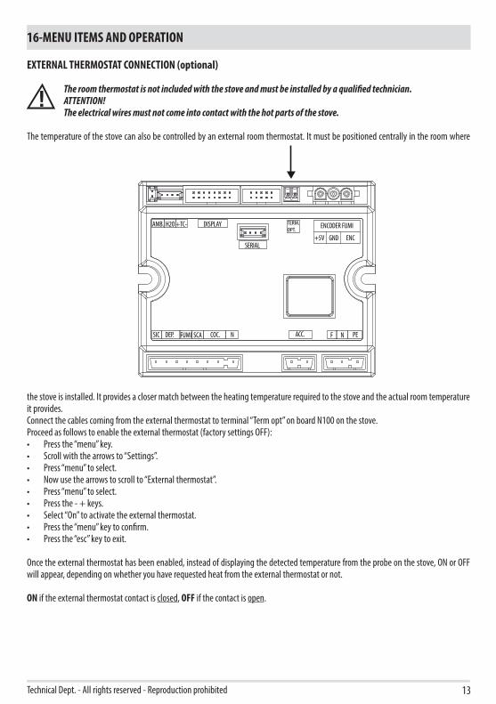
EXTERNAL THERMOSTAT CONNECTION (optional)
The room thermostat is not included with the stove and must be installed by a qualified technician.ATTENTION!The electrical wires must not come into contact with the hot parts of the stove.
The temperature of the stove can also be controlled by an external room thermostat. It must be positioned centrally in the room where
the stove is installed. It provides a closer match between the heating temperature required to the stove and the actual room temperature it provides. Connect the cables coming from the external thermostat to terminal “Term opt” on board N100 on the stove.Proceed as follows to enable the external thermostat (factory settings OFF):• Press the “menu” key.• Scroll with the arrows to “Settings”.• Press “menu” to select.• Now use the arrows to scroll to “External thermostat”.• Press “menu” to select.• Press the - + keys.• Select “On” to activate the external thermostat.• Press the “menu” key to confirm.• Press the “esc” key to exit.
Once the external thermostat has been enabled, instead of displaying the detected temperature from the probe on the stove, ON or OFF will appear, depending on whether you have requested heat from the external thermostat or not.
ON if the external thermostat contact is closed, OFF if the contact is open.

14
17-SAFETY DEVICES
SAFETY DEVICESThe product is fitted with the following safety devices
PRESSURE SWITCHMonitors pressure in the smoke duct. It is designed to shut down the pellet feed screw in the event of an obstructed flue or significant back-pressure (from wind).
SMOKE TEMPERATURE PROBEDetects the temperature of the smoke, thereby enabling start-up or stopping the product when the temperature drops below the preset value.
CONTACT THERMOSTAT IN THE FUEL TANKIf the temperature exceeds the preset safety level, it immediately shuts down the stove.
ELECTRICAL SAFETYThe stove is protected against violent changes in current by a general fuse located in the control panel at the back of the stove. Other fuses that protect the circuit boards are located on the latter.
SMOKE FANIf the fan stops, the circuit board immediately shuts off the supply of pellets and an alarm message is displayed.
GEAR MOTORIf the gear motor stops, the stove will continue to run until the flame goes out due to lack of fuel and until a minimum level of cooling is reached.
TEMPORARY POWER OUTAGEWhen a power outage lasts less than 10’’ the stove returns to its previous operating state. If it is longer, it executes a cooling/re-ignition cycle.
FAILED START-UPIf during ignition no flame develops, the stove will go into alarm condition.
TAMPERING WITH THE SAFETY DEVICES IS PROHIBITEDIf the product is NOT used as described in this instruction manual, the manufacturer declines all liability for any damage caused to persons and property. The manufacturer furthermore denies any liability for damage to persons and property arising from the failure to observe all the rules contained in the manual and specifically:• All the necessary measures and/or precautions must be adopted when performing maintenance, cleaning and
repairs.• Do not tamper with the safety devices.• Do not remove the safety devices.• Connect the product to an efficient smoke expulsion system.• First, check that the environment where it is to be installed is properly ventilated.
Only after having removed the cause that triggered the safety system is it possible to start the product again and therefore restore automatic operation of the probe. This manual will help you understand which anomaly has occurred, and explain how to operate according to the alarm message displayed on the appliance.

15
18-ALARMS
Technical Dept. - All rights reserved - Reproduction prohibited
ALARM SIGNALLINGWhen an operating condition other than the one expected for regular stove operation occur, an alarm is triggered.The reason for the alarm is shown on the control panel. The sound signal is not enabled for alarms A01-A02 in order not to disturb the user when there is an absence of pellets in the hopper during the night.
Panel signalling Type of problem Solution
A01
The flame does not light Check the level of pellets in the hopper. Check that the brazier is correctly positioned in its seat and has no encrustations or unburnt material.Make sure the glow plug warms up.Thoroughly empty and clean the brazier before restarting.
A02 The fire goes out abnormally. Check the level of pellets in the hopper.
A03Thermostat alarm
The temperature of the pellet hopper exceeds the required safety threshold.
Wait until the end of the cooling stage, stop the alarm and re-ignite the stove setting the supply of fuel to minimum (SETTINGS menu - Pellet recipe). If the alarm persists, contact the support centre.Check whether the room fan is working correctly.
A04 Smoke overtemperature. Reduce the load of pellets (SETTINGS menu - Pellet recipe). Check cleaning of the brazier.
A05Safety devices alarm
Smoke pressure switch triggered Check for chimney obstructions / door open
Fuel loading hatch Close the hatch.Lower the fuel level in the hopper.
Open stove door Close the door
A08 Anomalous operation of smoke fan. Delete the alarm and turn the stove on again. If the alarm persists, contact the support centre.
A09 Smoke sensor fault. Delete the alarm and turn the stove on again. If the alarm persists, contact the support centre.
ServiceRoutine maintenance warning (does not seize) When this blinking message appears upon start-up,
it means that the operating hours preset before maintenance have expired. Call the support centre.
ALARM RESETTo reset the alarm, press and hold key 1 (ESC) for a few seconds. The stove checks whether the cause of the alarm is ongoing.In the first case, the alarm continues to be displayed, in the second case it turns OFF.If the alarm persists, contact a support centre.

16
18-ALARMS
NORMAL SHUTDOWN (on the panel: OFF with flashing flame)When the shutdown key is pressed, or when there is an alarm signal, the stove enters the thermal extinguishing stage which involves automatic execution of the following stages:• Pellet loading stop• The room fan maintains the set speed until reaching the shutdown temperature• The smoke extractor fan is activated at maximum speed and remains on for a fixed period of 10 minutes, at the end of which if the
smoke T has dropped below the shutdown threshold, the fan stops, otherwise it will continue to operate at minimum speed until the temperature drops below the threshold and then turn off.
• If the stove has been shut down regularly but, due to thermal inertia, the smoke temperature exceeds the threshold again, the shutdown stage will be repeated at minimum speed until the temperature drops.
BLACKOUT WITH STOVE ONIn the event of a blackout, the stove does the following:
• Blackout less than 10”: resumes operation;• After a power outage of more than 10’’ which occurred when the stove was on, or during ignition, when the stove is powered again
it returns to its previous operating condition as follows:1. Cools the boiler by activating the smoke extractor at minimum speed for 10’ then proceeds to the next step;2. Restores the stove to the operating condition prior to the blackout.
During stage 1, the panel shows ON BLACK OUT.During stage 2, the panel shows Ignition.If during stage 1 the stove receives manual user commands from the control panel, it stops the blackout reset sequence and begins the start-up or shutdown as requested by the user.
BLACKOUT OF MORE THAN 10’’ DURING STOVE SHUTDOWNIf the stove experiences a loss of power GREATER THAN 10” while it is shutting down, when power is restored to the stove, it will automatically turn on in shutdown mode, even if the smoke temperature has fallen below 45°C in the meantime. This last stage can be skipped by pressing key 1 (esc) (skips to start-up) and pressing it again (recognises that the stove is off).
BLACKOUT OF MORE THAN 10’’ WITH THE STOVE OFF FOR ECOSTOPOnce power has been restored, a 5-minute timer is set as though the stove were in shutdown mode. Should there be a request for heat in these 5 minutes, the stove will not start.
SAFETY DEVICES ALARM A05The safety devices alarm includes operation of the smoke pressure switch, of the fuel loading hatch and of the open stove door.The alarm will be triggered after 30 seconds, after which the stove will stop working (e.g. after 30 seconds with the pellet loadinghatch open, alarm A05 will be triggered).
17
18-ALARMS
Technical Dept. - All rights reserved - Reproduction prohibited
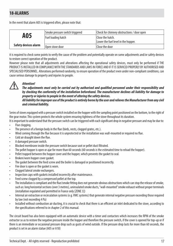
In the event that alarm A05 is triggered often, please note that:
A05Safety devices alarm
Smoke pressure switch triggered Check for chimney obstructions / door openFuel loading hatch Close the hatch.
Lower the fuel level in the hopper.Open stove door Close the door
it is required to check some points to verify the cause of the problem and potentially operate on some adjustments and/or safety devices to restore correct operation of the product.However please note that all adjustments and alterations affecting the operational safety devices, must only be performed if THE PRODUCT IS INSTALLED IN COMPLIANCE WITH THE STANDARDS AND LAWS IN FORCE AND IF IT IS SERVICED PROPERLY BY AUTHORISED AND SPECIALISED PERSONNEL. Alterations performed randomly, to ensure operation of the product even under non-compliant conditions, can cause serious damage to property and injuries to people.
Attention!The adjustments must only be carried out by authorised and qualified personnel under their responsibility and by checking the conformity of the installation beforehand. The manufacturer declines all liability for damage to property or injuries to people in the event of altering the safety devices.All liability for improper use of the product is entirely borne by the user and relieves the Manufacturer from any civil and criminal liability.
Series of stoves equipped with a pressure switch installed on the hopper with the sampling point positioned on the bottom, to the right of the gear motor. This system protects the whole system ensuring tightness of the stove throughout its duration.It is important to understand that the pressure switch can be triggered with each significant drop in negative pressure and may be due to:• Flue clogging.• The presence of a foreign body in the flue (birds, nests, clogged grates, etc.).• Wind coming through the flue because it is unprotected or the installation was wall-mounted or required no flue.• Cold air draught down the flue.• A damaged pressure switch.• Blocked membrane inside the pressure switch because soot or pellet dust filtrated.• The pellet hopper is open or ajar for more than 60 seconds (60 seconds is the estimated time to reload the hopper).• Pellet trapped between the hopper cover and the hopper, which prevents the gasket to seal.• Broken/worn hopper cover gasket.• The gasket between the feed screw and the boiler is damaged or positioned incorrectly.• Fire door is open or the gasket is worn.• Clogged lateral smoke exchangers.• Inspection caps with gaskets installed incorrectly after maintenance.• Feed screw clogged by a compressed pellet at the top.• The installation is compliant and the flue/smoke fitting does not generate obvious obstructions which can stop the release of smoke,
such as: long horizontal sections (over 3 metres), uninsulated smoke ducts, “wall-mounted” smoke exhaust without proper terminals (installation regulated and permitted in France only [ZONE 3])
• Internal air extraction or recirculation systems (e.g. VMC systems) that generate internal negative pressure exceeding those required by law (not exceeding 4 Pa)
• Installed without combustion air ducting, it is crucial to check that there is an efficient air inlet dedicated to the stove, according to the specifications referred to in chapter 2 of this manual.
The circuit board has also been equipped with an automatic device with a timer and contactors which increases the RPM of the smoke extractor so as to restore the negative pressure inside the hopper and therefore the pressure switch, if the cover is opened for top-up or if there is an immediate or occasional pressure drop such as gusts of wind outside. If the pressure drop lasts for more than 60 seconds, the product is set in an alarm statue (A05 or A18)
18
18-ALARMS
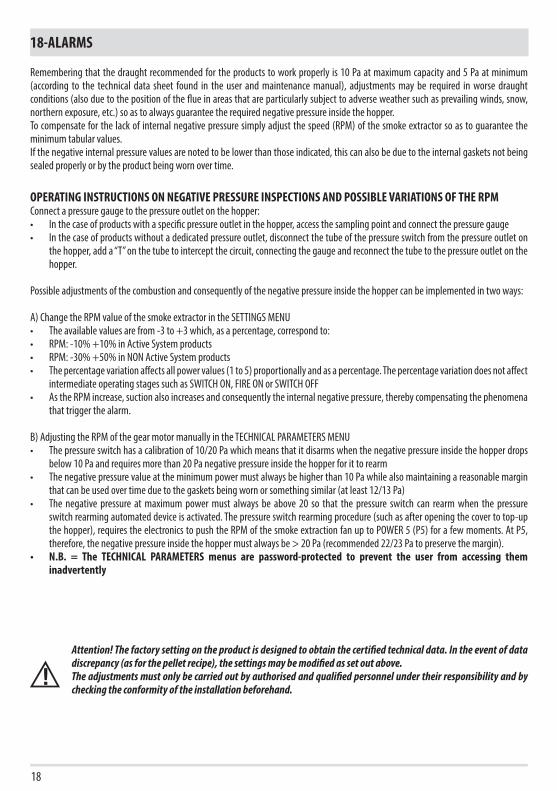
Remembering that the draught recommended for the products to work properly is 10 Pa at maximum capacity and 5 Pa at minimum (according to the technical data sheet found in the user and maintenance manual), adjustments may be required in worse draught conditions (also due to the position of the flue in areas that are particularly subject to adverse weather such as prevailing winds, snow, northern exposure, etc.) so as to always guarantee the required negative pressure inside the hopper.To compensate for the lack of internal negative pressure simply adjust the speed (RPM) of the smoke extractor so as to guarantee the minimum tabular values.If the negative internal pressure values are noted to be lower than those indicated, this can also be due to the internal gaskets not being sealed properly or by the product being worn over time.
OPERATING INSTRUCTIONS ON NEGATIVE PRESSURE INSPECTIONS AND POSSIBLE VARIATIONS OF THE RPMConnect a pressure gauge to the pressure outlet on the hopper:• In the case of products with a specific pressure outlet in the hopper, access the sampling point and connect the pressure gauge• In the case of products without a dedicated pressure outlet, disconnect the tube of the pressure switch from the pressure outlet on
the hopper, add a “T” on the tube to intercept the circuit, connecting the gauge and reconnect the tube to the pressure outlet on the hopper.
Possible adjustments of the combustion and consequently of the negative pressure inside the hopper can be implemented in two ways:
A) Change the RPM value of the smoke extractor in the SETTINGS MENU• The available values are from -3 to +3 which, as a percentage, correspond to: • RPM: -10% +10% in Active System products• RPM: -30% +50% in NON Active System products• The percentage variation affects all power values (1 to 5) proportionally and as a percentage. The percentage variation does not affect
intermediate operating stages such as SWITCH ON, FIRE ON or SWITCH OFF• As the RPM increase, suction also increases and consequently the internal negative pressure, thereby compensating the phenomena
that trigger the alarm.
B) Adjusting the RPM of the gear motor manually in the TECHNICAL PARAMETERS MENU• The pressure switch has a calibration of 10/20 Pa which means that it disarms when the negative pressure inside the hopper drops
below 10 Pa and requires more than 20 Pa negative pressure inside the hopper for it to rearm• The negative pressure value at the minimum power must always be higher than 10 Pa while also maintaining a reasonable margin
that can be used over time due to the gaskets being worn or something similar (at least 12/13 Pa)• The negative pressure at maximum power must always be above 20 so that the pressure switch can rearm when the pressure
switch rearming automated device is activated. The pressure switch rearming procedure (such as after opening the cover to top-up the hopper), requires the electronics to push the RPM of the smoke extraction fan up to POWER 5 (P5) for a few moments. At P5, therefore, the negative pressure inside the hopper must always be > 20 Pa (recommended 22/23 Pa to preserve the margin).
• N.B. = The TECHNICAL PARAMETERS menus are password-protected to prevent the user from accessing them inadvertently
Attention! The factory setting on the product is designed to obtain the certified technical data. In the event of data discrepancy (as for the pellet recipe), the settings may be modified as set out above. The adjustments must only be carried out by authorised and qualified personnel under their responsibility and by checking the conformity of the installation beforehand.

19
18-ALARMS
Technical Dept. - All rights reserved - Reproduction prohibited
NEGATIVE PRESSURE INSIDE THE HOPPER WITH FACTORY-SET PARAMETERS AND A DRAUGHT OF 5 Pa (MINIMUM RECOMMENDED)
POWER P1 P2 P3 P4 P5 VALUES
6 kW13.7/14.2 Pa 15.1/15.6 Pa 17.1/17.5 Pa 19.1/19.5 Pa 22.0/22.2 Pa Draught
95°C 110°C 125°C 141°C 165°C Smoke temperature
8 kW13.8/14.3 Pa 15.6/16.1 Pa 17.8/18.0 Pa 21.7/22.2 Pa 26.1/26.6 Pa Draught
104°C 119°C 145°C 148°C 184°C Smoke temperature
10 kW15.9/16.3 Pa 20.4/20.9 Pa 25.8/26.3 Pa 31.8/32.3 Pa 36.5/37.0 Pa Draught
108°C °C 150°C °C 230°C Smoke temperature
12 kW16.5/17.3 Pa 20.4/20.9 Pa 25.8/26.3 Pa 31.8/32.3 Pa 36.5/37.1 Pa Draught
118°C 127°C 155°C 172°C 195°C Smoke temperature
14 kW17.6/18.0 Pa 19.8/20.4 Pa 23.1/23.7 Pa 28.9/29.6 Pa 37.8/38.2 Pa Draught
118°C 131°C 161°C 187°C 210°C Smoke temperature
PLEASE NOTE The indicated negative pressure readings may differ by ±1Pa based on flue gas temperature. Likewise, flue gas temperature may differ by ±10°C based on fuel quality or appliance cleanliness.
Changing the smoke fan revolutionsIn the event the installation presents problems in extracting smoke (lack of draft or even pressure in the duct), it is possible to increase the smoke and ash extraction speed. This change resolves all potential problems related to pellets clogged in the brazier and deposits forming at the bottom of the brazier itself caused by poor quality fuel or fuel that produces a lot of ash. The values available range from -30% to +50%, with increments of 10 percent at a time. Negative variation may be required if the flame is too low.
To alter this parameter, proceed as follows:• Press the “menu” key.• Use the arrow keys to scroll through and select “Settings”• Press “menu” to confirm.• Scroll with the arrows and select “Fume rpm Var.”• Press “menu” to confirm.• Edit the % by using the + - keys.• Press ‘’menu’’ to confirm and ‘’esc’’ to exit.

20
19-RECOMMENDATIONS FOR SAFE USE
ONLY CORRECT INSTALLATION AND APPROPRIATE MAINTENANCE AND CLEANING OF THE APPLIANCE CAN GUARANTEE CORRECT OPERATION AND SAFE USE OF THE PRODUCT.
We would like to inform you that we are aware of cases of malfunctioning of domestic pellet-fuelled heating products, mainly due to incorrect installation and use, as well as inadequate maintenance.We would like to assure you that all of our products are extremely safe and certified according to European standards of reference. The ignition system has been tested with the utmost attention to enhance ignition efficiency and to prevent any type of problem, even in the worst operating conditions. In any case, like for any other pellet-fuelled product, our appliances must be installed correctly and undergo regular periodical cleaning and maintenance to guarantee safe operation. Our studies show us that malfunctioning is mainly due to the combination of part or all of the following factors:• Brazier holes obstructed or brazier deformed, due to lack of maintenance and conditions which can cause delayed ignitions,
generating an anomalous production of unburnt gases. • Insufficient combustion air due to a reduced or clogged air inlet duct. • Use of smoke ducts nonconforming to regulatory installation requirements, failing to guarantee an adequate draught. • Partially clogged chimney, due to lack of maintenance, reducing the draught and making ignition difficult. • End chimney pot not conforming to the indications of the instruction manual, and therefore not suitable to prevent potential inverse
draught. • This factor is crucial when the product is installed in especially windy areas, such as coastal regions.
The combination of one or more of these factors may generate severe malfunctioning conditions.To keep this from occurring, it is crucial to guarantee that the product is installed in compliance with standards in force.Furthermore it is of the utmost importance to comply with the following simple rules:• Every time the brazier is removed for cleaning, it must always be put back properly in the work position before using the product,
completely removing any residual dirt left on the support base.• Pellets must never be loaded in the brazier manually, either before ignition or during operation.• The buildup of unburnt pellets following a failed ignition must be removed before repeating ignition. Also check that they are fed
correctly and that the combustion air inlet/smoke outlet are regular.• If ignition fails repeatedly, immediately suspend use of the product and contact a qualified technician to check its operation.
Compliance with these indications is absolutely sufficient to ensure proper operation and to avoid any type of problems with the product.If the aforementioned precautions are not taken, and during ignition the brazier is overloaded with pellets thus generating anomalous smoke in the combustion chamber, carefully follow the indications below:• Do not disconnect electrical power to the product for any reason whatsoever: this would stop the smoke extractor, releasing smoke
into the environment.• Take the precaution of opening the windows to ventilate the installation room from any smoke in the environment (the chimney
might not work properly).• Do not open the fire door: this would compromise regular operation of the smoke extraction system to the chimney.• Simply switch the stove off by operating on the on-off button on the control panel (not the rear power supply socket button!) and
move away until smoke has been completely extracted.• Before attempting re-ignition, clean the brazier and its air passage holes completely of all deposits and unburned pellets. Put
the brazier back in place, removing any residue from its support base. If ignition fails repeatedly, immediately suspend use of the product and contact a qualified technician to check its operation and the chimney.
b21
20-CLEANING
Technical Dept. - All rights reserved - Reproduction prohibited
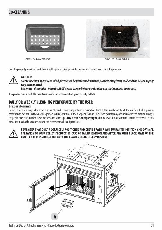
Only by properly servicing and cleaning the product is it possible to ensure its safety and correct operation.
CAUTION!All the cleaning operations of all parts must be performed with the product completely cold and the power supply plug disconnected.Disconnect the product from the 230V power supply before performing any maintenance operation.
The product requires little maintenance if used with certified good quality pellets.
DAILY OR WEEKLY CLEANING PERFORMED BY THE USERBrazier cleaningBefore ignition, always clean the brazier “b” and remove any ash or incrustation from it that might obstruct the air flow holes, paying attention to hot ash. In the case of ignition failure, or if fuel in the hopper runs out, unburned pellets may accumulate in the brazier. Always empty the residue in the brazier before each start-up. Only if ash is completely cold may a vacuum cleaner be used to remove it. In this case, use a suitable vacuum cleaner to remove small sized particles.
REMEMBER THAT ONLY A CORRECTLY POSITIONED AND CLEAN BRAZIER CAN GUARANTEE IGNITION AND OPTIMAL OPERATION OF YOUR PELLET PRODUCT. IN CASE OF FAILED IGNITION AND AFTER ANY OTHER LOCK STATE OF THE PRODUCT, IT IS ESSENTIAL TO EMPTY THE BRAZIER BEFORE EVERY RESTART.
EXAMPLE OF A CLEAN BRAZIER EXAMPLE OF A DIRTY BRAZIER

P
22
20-CLEANING
For the brazier to be cleaned properly, fully remove it from its housing and thoroughly clean all the holes and the grate on the bottom. If high quality pellets are used, you will normally only need to use a brush to restore the optimal operating conditions of the component.Cleaning the ash collection compartmentTo clean the ash collection compartment, extract the ash pan “P”. Remove any residual ash before reinserting the pan. Your experience and the quality of the pellets used will determine how often the ash pan must be cleaned.However, it is recommended not to exceed 2 or 3 days.
Attention! Once cleaning is completed, remember to place back the ash pan “P”, insert the brazier “b” and close the firebox door.
F
F
F - F
q
R
x
q
23
20-CLEANING
Technical Dept. - All rights reserved - Reproduction prohibited
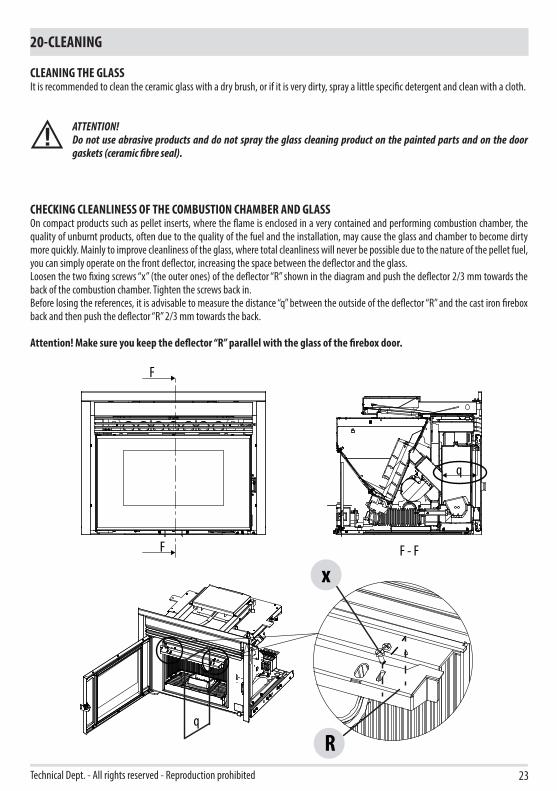
CLEANING THE GLASSIt is recommended to clean the ceramic glass with a dry brush, or if it is very dirty, spray a little specific detergent and clean with a cloth.
ATTENTION!Do not use abrasive products and do not spray the glass cleaning product on the painted parts and on the door gaskets (ceramic fibre seal).
CHECKING CLEANLINESS OF THE COMBUSTION CHAMBER AND GLASSOn compact products such as pellet inserts, where the flame is enclosed in a very contained and performing combustion chamber, the quality of unburnt products, often due to the quality of the fuel and the installation, may cause the glass and chamber to become dirty more quickly. Mainly to improve cleanliness of the glass, where total cleanliness will never be possible due to the nature of the pellet fuel, you can simply operate on the front deflector, increasing the space between the deflector and the glass.Loosen the two fixing screws “x” (the outer ones) of the deflector “R” shown in the diagram and push the deflector 2/3 mm towards the back of the combustion chamber. Tighten the screws back in. Before losing the references, it is advisable to measure the distance “q” between the outside of the deflector “R” and the cast iron firebox back and then push the deflector “R” 2/3 mm towards the back.
Attention! Make sure you keep the deflector “R” parallel with the glass of the firebox door.
x
H
F G L
24
20-CLEANING
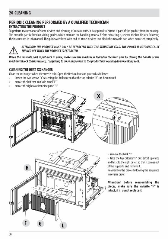
PERIODIC CLEANING PERFORMED BY A QUALIFIED TECHNICIANEXTRACTING THE PRODUCTTo perform maintenance of some devices and cleaning of certain parts, it is required to extract a part of the product from its housing. The movable part is fitted on sliding guides, which promote the handling process. Before extracting it, release the handle lock following the instructions in this manual. The guides are fitted with end-of-travel devices that block the movable part when extracted completely.
ATTENTION: THE PRODUCT MUST ONLY BE EXTRACTED WITH THE STRUCTURE COLD. THE POWER IS AUTOMATICALLY TURNED OFF WHEN THE PRODUCT IS EXTRACTED.
When the movable part is put back in place, make sure the machine is locked to the fixed part by closing the handle or the mechanical lock (Basic version). Forgetting to do so may result in the product not working due to leaking soot.
CLEANING THE HEAT EXCHANGERClean the exchanger when the stove is cold. Open the firebox door and proceed as follows:• loosen the two screws “x” fastening the deflector so that the top calorite “H” can be removed• extract the left cast iron side panel “F”• extract the right cast iron side panel “L”
• remove the back “G”• take the top calorite “H” out. Lift it upwards and tilt it to the right or left so that it comes out of the supports and remove it.Reassemble the pieces following the sequence in reverse order.
Attention! Before reassembling the pieces, make sure the calorite “H” is intact, if in doubt replace it.

1
2
z
O
P
z
O
P
Lkr
25
20-CLEANING
Technical Dept. - All rights reserved - Reproduction prohibited
Use a flexible brush to scrape the walls of the firebox (arrow 1 in the figure) so as to make the ash fall into the ash pan.Use a vacuum cleaner nozzle to vacuum up any remaining ash and dust in the ash pan and brazier zone.Repeatedly pass it between the exchangers pipes (arrow 2 in the figure) to remove the fuel deposits and residues.
With the product extracted, remove the screws “z”, the plate “P” and the gasket “O” at the bottom and on the side and use a vacuum cleaner to remove any remaining ash residues. Before putting the plate “P” back in place, change the gasket “O”.
It is also advisable to vacuum near to the coupling “r” and “k” and remove and clean the smoke fan “L”.
26
20-CLEANING
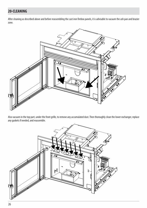
After cleaning as described above and before reassembling the cast iron firebox panels, it is advisable to vacuum the ash pan and brazier zone.
Also vacuum in the top part, under the front grille, to remove any accumulated dust. Then thoroughly clean the lower exchanger, replace any gaskets if needed, and reassemble.
13
2
4
27
20-CLEANING
Technical Dept. - All rights reserved - Reproduction prohibited
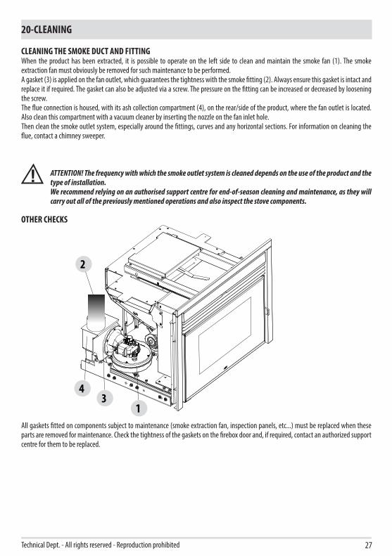
CLEANING THE SMOKE DUCT AND FITTINGWhen the product has been extracted, it is possible to operate on the left side to clean and maintain the smoke fan (1). The smoke extraction fan must obviously be removed for such maintenance to be performed.A gasket (3) is applied on the fan outlet, which guarantees the tightness with the smoke fitting (2). Always ensure this gasket is intact and replace it if required. The gasket can also be adjusted via a screw. The pressure on the fitting can be increased or decreased by loosening the screw.The flue connection is housed, with its ash collection compartment (4), on the rear/side of the product, where the fan outlet is located. Also clean this compartment with a vacuum cleaner by inserting the nozzle on the fan inlet hole.Then clean the smoke outlet system, especially around the fittings, curves and any horizontal sections. For information on cleaning the flue, contact a chimney sweeper.
ATTENTION! The frequency with which the smoke outlet system is cleaned depends on the use of the product and the type of installation.We recommend relying on an authorised support centre for end-of-season cleaning and maintenance, as they will carry out all of the previously mentioned operations and also inspect the stove components.
OTHER CHECKS
All gaskets fitted on components subject to maintenance (smoke extraction fan, inspection panels, etc...) must be replaced when these parts are removed for maintenance. Check the tightness of the gaskets on the firebox door and, if required, contact an authorized support centre for them to be replaced.
X
28
20-CLEANING
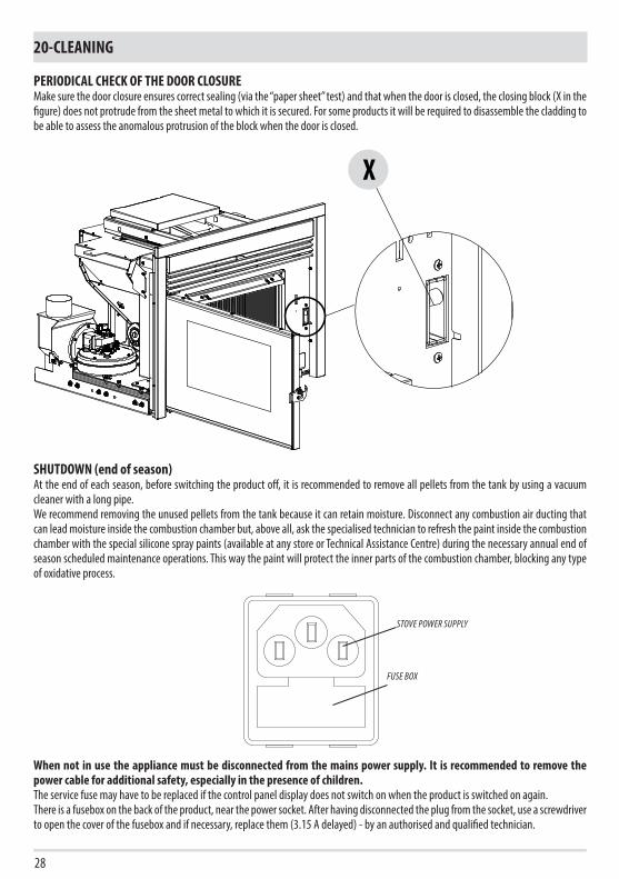
PERIODICAL CHECK OF THE DOOR CLOSUREMake sure the door closure ensures correct sealing (via the “paper sheet” test) and that when the door is closed, the closing block (X in the figure) does not protrude from the sheet metal to which it is secured. For some products it will be required to disassemble the cladding to be able to assess the anomalous protrusion of the block when the door is closed.
SHUTDOWN (end of season)At the end of each season, before switching the product off, it is recommended to remove all pellets from the tank by using a vacuum cleaner with a long pipe.We recommend removing the unused pellets from the tank because it can retain moisture. Disconnect any combustion air ducting that can lead moisture inside the combustion chamber but, above all, ask the specialised technician to refresh the paint inside the combustion chamber with the special silicone spray paints (available at any store or Technical Assistance Centre) during the necessary annual end of season scheduled maintenance operations. This way the paint will protect the inner parts of the combustion chamber, blocking any type of oxidative process.
When not in use the appliance must be disconnected from the mains power supply. It is recommended to remove the power cable for additional safety, especially in the presence of children.The service fuse may have to be replaced if the control panel display does not switch on when the product is switched on again.There is a fusebox on the back of the product, near the power socket. After having disconnected the plug from the socket, use a screwdriver to open the cover of the fusebox and if necessary, replace them (3.15 A delayed) - by an authorised and qualified technician.
STOVE POWER SUPPLY
FUSE BOX

29
20-CLEANING
Technical Dept. - All rights reserved - Reproduction prohibited
CHECKING THE INTERNAL COMPONENTS
ATTENTION!The internal electromechanical components must only be checked by qualified personnel whose technical expertise includes combustion and electricity.
We recommend for this yearly maintenance to be carried out (with a scheduled service contract). This operation consists of a visual and functional inspection of the internal components. A summary of the checks and/or maintenance operations that are essential for the correct operation of the product is provided below.
PARTS/INTERVAL 1 DAY 2-3 DAYS 1 YEAR
UNDE
R TH
E US
ER'S
RESP
ONSIB
ILITY
Brazier ·Ash pan ·Glass ·
BY TH
E QUA
LIFIED
TECH
NICIA
N
Heat exchanger ·Smoke duct ·Gaskets ·Door closure operation ·
REPLACING GASKETS AFTER 1 SEASON OF OPERATION
• SMOKE CAP GASKET
• DOOR SEAL GASKET D.10
• DOOR SEAL GASKET D.5
• SMOKE FAN GASKET
AND FOR THE SLIDE VERSION
• SMOKE BOX SILICONE GASKET

30
21-FAULTS/CAUSES/SOLUTIONS
ATTENTION: All repairs must only be carried out by a specialised technician, with the product switched off and the electrical plug disconnected.
ANOMALY POTENTIAL CAUSES SOLUTIONS
The pellets are not fed into the combustion chamber.
The pellet hopper is empty Fill the hopper with pellets.
Sawdust has blocked the feed screw Empty the hopper and remove the sawdust from the feed screw by hand.
Faulty gear motor Replace the gear motor.
Faulty circuit board Replace the electronic board.
The fire goes out or the boiler stops automatically.
The pellet hopper is empty Fill the hopper with pellets.
The pellets are not fed See the previous anomaly.
The pellet temperature safety probe has been triggered
Let the product cool down, restore the thermostat until the lockout is removed and switch the product back on. If the problem persists, contact Technical Support.
The door is not closed properly or the gaskets are worn
Close the door and replace the gaskets with original ones.
Unsuitable pellets Change the type of pellets with those recommended by the manufacturer.
Low pellet supply Check the flow of fuel following the instructions in the manual.
The combustion chamber is dirty Clean the combustion chamber, following the instructions in the manual.
Clogged outlet Clean the smoke duct.
Faulty smoke extraction motor Check the motor and replace it, if required.
Pressure switch faulty or defective. Replace the pressure switch.
The product works for a few minutes and then switches off.
Ignition stage not completed Repeat the ignition stage.
Temporary power outage Wait for the automatic restart.
Clogged smoke duct Clean the smoke duct.
Faulty or malfunctioning temperature probes Check and replace the probes.
Faulty glow plug Check the glow plug and replace it, if required.

31
21-FAULTS/CAUSES/SOLUTIONS
Technical Dept. - All rights reserved - Reproduction prohibited
ANOMALY POTENTIAL CAUSES SOLUTIONS
Pellets accumulate in the brazier, the glass of the door gets dirty and the flame is weak.
Insufficient combustion air. Clean the brazier and check that all the holes are clear. Perform a general cleaning of the combustion chamber and the smoke duct. Check that the air inlet is not obstructed.
Damp or unsuitable pellets. Change the type of pellets.
Faulty smoke extraction motor. Check the motor and replace it, if required.
The smoke extractor motor does not work.
No electrical supply to the stove. Check the mains voltage and the protection fuse.
The motor is faulty. Check the motor and capacitor and replace them, if necessary.
Faulty motherboard. Replace the circuit board.
The control panel is broken. Replace the control panel.
The convection air fan never stops. Faulty or malfunctioning temperature control probe.
Check the probe and replace it, if required.
In the automatic position, the stove always runs at full power.
Thermostat set to minimum. Reset the temperature of the thermostat.
The room thermostat is in maximum position.
Reset the temperature of the thermostat.
Malfunctioning temperature probe. Check the probe and replace it if required.
Faulty or malfunctioning control panel. Check the panel and replace it, if required.
The product does not start. No power supply. Check that the plug is inserted and the main switch is in the “I” position.
Pellet sensor has seized up. Check the recipe parameters.
Faulty fuse. Replace the fuse.
Pressure switch faulty (lockout indicated). Insufficient pressure of water in stove.
Clogged the smoke outlet or smoke duct. Clean the smoke outlet and/or the smoke duct.
Noisy air fan even though it is set to minimum
High set flame causes ventilation increase Lower set flame from Adjustments menu

32
21-FAULTS/CAUSES/SOLUTIONS
ANOMALY POTENTIAL CAUSES SOLUTIONS
No increase in temperature with stove in operation.
Incorrect combustion adjustment. Check recipe.
Set flame 1 setting (level too low) Increase power from the settings menu.
Poor pellet quality. Use pellets from the manufacturer.
AMB. H2O +TC- DISPLAY
SERIAL
SIC DEP. FUMI SCA COC. N ACC. F N PE
TERM.OPT.
+5V GND ENC
ENCODER FUMI
41 3 52
6789
101112
33
22-CIRCUIT BOARD
Technical Dept. - All rights reserved - Reproduction prohibited
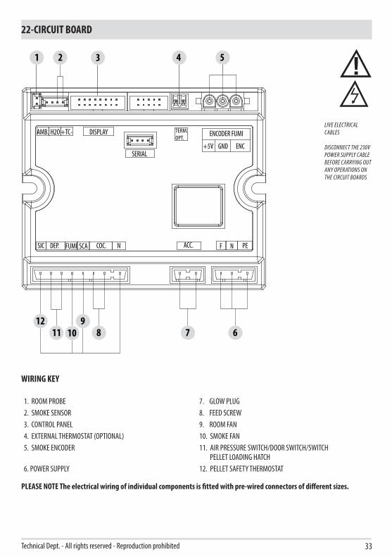
WIRING KEY
1. ROOM PROBE 7. GLOW PLUG2. SMOKE SENSOR 8. FEED SCREW3. CONTROL PANEL 9. ROOM FAN4. EXTERNAL THERMOSTAT (OPTIONAL) 10. SMOKE FAN5. SMOKE ENCODER 11. AIR PRESSURE SWITCH/DOOR SWITCH/SWITCH
PELLET LOADING HATCH6. POWER SUPPLY 12. PELLET SAFETY THERMOSTAT
PLEASE NOTE The electrical wiring of individual components is fitted with pre-wired connectors of different sizes.
LIVE ELECTRICAL CABLES
DISCONNECT THE 230V POWER SUPPLY CABLE BEFORE CARRYING OUT ANY OPERATIONS ON THE CIRCUIT BOARDS


04/09/2018REV.08901845900
Via La Croce n°833074 Vigonovo di Fontanafredda (PN) – ITALY
Telephone: +39 0434/997200Internet : www.red365.it
e-mail : [email protected]


![Bridge FinalReport s1 - Columbia University › ~sedwards › classes › 2009 › w4115... · header[1-6] para bold line button open close insert comment 3.3 Types Bridge is a single](https://img.pdfslide.us/doc/110x75/5f1e8ffe9bfafe0b415672d4/bridge-finalreport-s1-columbia-a-sedwards-a-classes-a-2009-a-w4115.jpg)


![Facilitator: [Insert name] Date: [Insert] Venue: [Insert] Wellcome !](https://img.pdfslide.us/doc/110x75/56649dd05503460f94ac59be/facilitator-insert-name-date-insert-venue-insert-wellcome-.jpg)