Embed Size (px)
Citation preview

1
"InSafeJIP"
IMPROVED GUIDELINES FOR THE PREDICTION OF GEOTECHNICAL PERFORMANCE OF SPUDCAN FOUNDATIONS
DURING INSTALLATION AND REMOVAL OF JACK-UP UNITS
Joint Industry-funded Project
RPS Energy, Goldsworth House, Denton Way, Goldsworth Park, Woking, Surrey, GU21 3LG, UK
T +44 (0)1483746500 F +44 (0) 1483746505
E [email protected] W www.rpsgroup.com
Authors: Osborne, J.J., Teh, K.L. , Houlsby, G.T., Cassidy, M.J., Bienen, B. and Leung, C.F.
Ref: EOG0574-Rev1c
E-mail: [email protected] Date: 28th March 2011

InSafeJIP Guideline
2
DISCLAIMER This Guideline is the final deliverable of the InSafeJIP Project which has been sponsored by the companies listed below. Technical, project and administrative management of the Project was provided by RPS Energy. Use of the contents of this Guideline shall be solely at the user’s own discretion and risk and no other party shall be liable for any damage resulting from any inaccuracy, incorrectness, unsoundness and/or unreliability in its use. The Guideline is provided without any representation or warranty of any kind, either express or implied, including but not limited to being of satisfactory quality or fitness for a particular purpose. The opinions expressed in the Guideline are not necessarily supported by each participant, author, project team member or subcontractor.
In no event shall RPS, the Project Sponsors or the Project Subcontractors or any individuals named in the Guideline be liable for any damages whatsoever and howsoever caused, including (without limitation) liability in negligence and liability for any special, indirect, consequential or incidental damages or damages for loss of profits, revenue or use of data arising out of or in connection with the use of the Guideline or the results and/or recommendations contained therein. The InSafeJIP Project Sponsors, RPS Energy and its subcontractors who performed the Project make no commitment to provide any technical consultancy or other such services in support of the Guideline. This Guideline was prepared with technical, project and administrative management by RPS Energy Ltd and its Subcontractors listed below. Funding was provided by the Project sponsors also listed below:
Project Sponsors Company Name Company Representatives American Bureau of Shipping Dr. J. F. Wu Dr. X. Y. Zhang Braemar Falconer Mr. P. Handidjaja Capt. J. B. Fawcett ConocoPhillips Mr. J. B. Ferguson Mr. G. L. Holloway Mr. B. Borland Mr. K. Lynch DONG Energy Dr. M. A. Liingaard ENSCO International Mr. D. C. Martin Mr. R. R. Roper EXXONMobil Development Company Mr. P. C. Wong Dr. A. M. E. Audibert Fugro Singapore Pte Ltd Mr. J. M. Paisley Ms. N. Chan Mr. D. Menzies GEO-Danish Geotechnical Institute Dr. L. Kellezi GL Noble Denton Mr. M. J. R. Hoyle Dr. D. Edwards Dr. K. Hau

InSafeJIP Guideline
3
Global Maritime Mr. B. Hodges
Mr. G. Hogg Dr. A. Morandi HSE UK Mr. R. Martland Mr. W. Jones Keppel Offshore & Marine Technology Centre Pte Ltd. Dr. K. S. Foo Dr. M. Quah Dr. O. Purwana Dr. H. Krisdani Mærsk Drilling Mr. G. Kudsk Mr. H. Stadsgaard Matthews Daniel Mr. S. D. Devoy Mrs. C. Rainer-Lopez Noble Drilling (Land Support) Ltd Mr. B. Robaard Mr. J. Mogensen Mr. P. Driessens Premier Oil and Gas Services Ltd Mr. C. Ellis Mr. T. J. J. Hanson Premium Drilling / COSL Mr. S. Nowak Shell UK Limited Mr. R. Hunt Dr. R. F. Overy Transocean (Global Santa Fe) Mr. M. Lawson Mr. J. Brekke Mr. D. Kennedy Project Management RPS Energy Mr. J. J. Osborne Mrs. S. Hartley Mrs. C. Bishop Project Subcontractors National University of Singapore Prof. C. F. Leung Project Analyst Dr. K. L. Teh Department of Engineering Science, University of Oxford Prof. G. T. Houlsby Dr. C. M. Martin The University of Western Australia Prof. M. Cassidy Prof. M. F. Randolph Dr. B. Bienen Dr. M. S. Hossain
Date Reference Description Revision
22 April 10 EOG0574-Rev0 First issued for comments 0
27 July 10 EOG0574-Rev1 Final InSafeJIP document. 1
15 Nov 10 EOG0574-Rev1a Final InSafeJIP document (errata) 1a
18 Nov 10 EOG0574-Rev1b Final InSafeJIP document (errata) 1b
28 Mar 11 EOG0574-Rev1c Final InSafeJIP document 1c
© Copyright 2011 RPS Energy Ltd on behalf of the InSafeJIP

InSafeJIP Guideline
4
Contents
List of figures........................................................................................................................... 6 List of tables............................................................................................................................ 7 1. Introduction ..................................................................................................................... 8
1.1 InSafeJIP objectives................................................................................................ 8 1.2 InSafeJIP summary statement ................................................................................ 8 1.3 Guideline purpose ................................................................................................... 8 1.4 Guideline structure .................................................................................................. 9
2. Geotechnical site investigation requirements for spudcan foundation assessment...... 10 2.1 Background and aims............................................................................................ 10 2.2 Geotechnical site investigation planning ............................................................... 11 2.3 Geotechnical work scope ...................................................................................... 12 2.4 Sampling and field testing ..................................................................................... 18 2.5 Soil laboratory testing............................................................................................ 19
3. Geotechnical data interpretation and soil engineering parameter selection ................. 21 3.1 Background and aims............................................................................................ 21 3.2 Identification of soil type and layers ...................................................................... 21
3.3 Clay: Undrained shear strength, us , and other parameters ................................. 22
3.3.1 Interpretation of us based on in-situ testing results....................................... 22
3.3.2 Interpretation of us based on high quality laboratory testing results ............. 25
3.3.3 Interpretation of us based on simple laboratory testing results ..................... 26
3.3.4 Determination of remoulded shear strength or sensitivity ............................. 27 3.3.5 Determination of other soil parameters ......................................................... 28
3.4 Sand: Selection of friction angle............................................................................ 28 3.4.1 Based on in-situ testing results...................................................................... 29 3.4.2 Based on high quality laboratory testing results ............................................ 31 3.4.3 Effects of compressibility and progressive mobilisation ................................ 32
3.5 Soil strength parameters for soils of intermediate drainage properties ................. 32 3.6 Derivation of soil strength profile ........................................................................... 35
3.6.1 Determining the strength profile with depth ................................................... 35 3.6.2 Determining confidence bands on the soil strength profile............................ 37
4. Prediction of spudcan penetration................................................................................. 38 4.1 Background and aims............................................................................................ 38 4.2 Basis of spudcan penetration prediction methods................................................. 39

InSafeJIP Guideline
5
4.3 Spudcan penetration in clay.................................................................................. 41 4.4 Spudcan penetration in sand................................................................................. 43 4.5 Spudcan penetration in layered materials ............................................................. 46
4.5.1 Strength averaging methods ......................................................................... 47 4.5.2 Mechanism based methods .......................................................................... 49
4.6 Time-dependent effects......................................................................................... 53 4.6.1 Scour ............................................................................................................. 53 4.6.2 Partial drainage ............................................................................................. 53 4.6.3 Other rate effects........................................................................................... 54
4.7 Alternative approaches.......................................................................................... 54 4.7.1 Direct correlation with penetrometer tests ..................................................... 54 4.7.2 Hossain and Randolph approach .................................................................. 55
4.8 Variability of parameters and accuracy of calculations ......................................... 55 4.8.1 Accuracy of calculations................................................................................ 55 4.8.2 Observed spudcan penetration performance ................................................ 57
5. Ground preparation ....................................................................................................... 61 5.1 Background and aims............................................................................................ 61 5.2 Scour protection .................................................................................................... 61 5.3 Perforation drilling ................................................................................................. 62 5.4 Other ground preparation methods ....................................................................... 63
6. Jack-up installation, operational considerations and spudcan extraction ..................... 65 6.1 Background and aims............................................................................................ 65 6.2 Installation procedures .......................................................................................... 65
6.2.1 Remedial action following rapid spudcan penetration ................................... 73 6.3 Operational considerations.................................................................................... 73 6.4 Spudcan extraction................................................................................................ 74
6.4.1 breakoutQ for spudcan extraction in clay ........................................................ 74
6.4.2 Aided extraction methods for jack-up removal .............................................. 75 List of notations..................................................................................................................... 80 List of abbreviations .............................................................................................................. 85 References............................................................................................................................ 86 Appendices ........................................................................................................................... 91

InSafeJIP Guideline
6
List of figures Figure 3.1 Variation of 'φ with 'p given by Eqns. 3.4.3 and 3.4.4
Figure 3.2 Normalised cone resistance versus normalised velocity for various soil stiffness ratios
Figure 4.1 Definition of penetration depths z and h
Figure 4.2 Definition of equivalent cone
Figure 4.3 Backflow in sand
Figure 4.4 Strength averaging procedure
Figure 4.5 Nomenclature for spudcan penetration in sand over clay
Figure 4.6 Nomenclature of spudcan penetration in sand over clay when layerhh ≥ Figure 4.7 Nomenclature of spudcan penetration in strong clay over soft clay
Figure 4.8 Nomenclature of spudcan penetration in soft clay over hard stratum clay
Figure 4.9 Cumulative distribution of ratio of observed to predicted resistance
Figure 6.1 Aided extraction methods
Figure A2.4.2.1 Terminology for piezocone
Figure A3.2.1.1 New piezocone soil classification charts in various plotting formats
Figure A3.6.1.1 CoV of each shear strength testing method
Figure A4.5.2.1 cN values for spudcan bearing capacity calculation when layerhh ≥
Figure A4.5.4.1 Values of cN ' Figure A4.7.1.1 Normalized cone resistance versus non-dimensional velocity for various
pG ′ ratios
Figure A5.3.1.1 Schematic of components of resistance acted on perforation system
Figure A5.3.1.2 Comparison of theoretical and experimental percentage reduction in peakVQ ,
Figure A6.4.1.1 Mechanism of an embedded spudcan during extraction
Figure A6.4.1.2 Back-calculated breakoutN
Figure A6.4.1.3 Variation in topf and basef with operational period

InSafeJIP Guideline
7
List of tables Table 2.1 Properties required for jack-up foundation site specific assessment
Table 2.2 Geotechnical work scope for open locations for simple geological conditions
Table 2.3 Geotechnical work scope for open locations for complex and very complex geological conditions
Table 2.4 Geotechnical work scope for work-over locations for simple to very complex geological settings
Table 2.5 Reliability of tests in measuring strength parameters of clays
Table 3.1 Ratios of average UU strengths to other simple laboratory and cone penetration test data (derived from InSafeJIP database)
Table 3.2 Ratios of strengths derived from a cone ( 5.13=ktN ) to other simple laboratory test data (derived from InSafeJIP database)
Table 3.3 Values of crushingQ and cvφ derived from triaxial compression tests
Table 3.4 Ratio of frictional strengths from cone and laboratory tests
Table 3.5 V values for different penetrometers in different soil types
Table 4.1 Measured/predicted load ratios for spudcans in clay
Table 4.2 Categories of observed response and suggested actions
Table 4.3 Summary of spudcan penetration behaviour in strongly layered systems
Table 6.1 Recommended preloading strategies for spudcan installation in single-layered soil
Table 6.2 Recommended preloading strategies for spudcan installation in strongly layered soils
Table 6.3 Aided extraction methods for jack-up removal
Table A2.5.2.1 Test frequency for onshore and offshore laboratory testing
Table A3.6.1.1 Summary of CoV of tools derived from InSafeJIP database

InSafeJIP Guideline
8
1. Introduction
1.1 InSafeJIP objectives The recent safety record of jack-up installation and removal operations suggests that procedural improvements are necessary and as a result this study, entitled the “InSafeJIP”, was launched with the following objectives :
A. Review the available spudcan penetration prediction, extraction and ground preparation methods. Collect, process, catalogue and analyse jack-up foundation performance case study data sets. Where possible calibrate the predictive and ground preparation methods with the case records. Assess and determine the best methods for improving the reliable prediction of jack-up installation and removal.
B. Codify the above in a way that is readily accessible to analysts, and produce an up-to-date set of geotechnical site assessment and operational guidelines.
C. Identify gaps in knowledge and experience and recommend future R&D work to close the knowledge gaps.
In summary the principal objective of this Project has been to investigate and develop improved jack-up geotechnical procedures for site assessment, ground treatment and foundation performance prediction and incorporate these within a Guideline document (this document).
This Guideline is written as a stand-alone document, with relevant references to the project outcomes in the Appendices. However, further details of the InSafeJIP project review, analysis, investigations and outcomes are reported in the InSafeJIP 1st Year Report (InSafeJIP, 2009).
1.2 InSafeJIP summary statement The InSafeJIP initiative was conceived by RPS Energy and announced on the 6th December 2006 in Singapore, with a Project Launch Status Meeting being held on 30th May 2007 in Houston. From its inception the Project has been actively supported and promoted by Keppel FELS.
A database with 146 case study data sets of various degrees of quality supplied by the project participants was established with the geographical distribution of the data sets spanning from Australasia to America, Europe, Africa and the Middle East. The data sets were processed, examined and, if suitable, utilised for various calibration purposes with an ultimate aim to derive recommendations for improving the reliable prediction of jack-up installation and removal.
The recommendations provided in the Guideline should only be used for guidance and do not imply any legislative requirements, responsibilities or guarantee of applicability. The Guideline should be interpreted by a competent geotechnical engineer with reference to other literature when applicable.
1.3 Guideline purpose The purpose of this Guideline is to provide improved methods for the following jack-up foundation related procedures :
Site characterisation, investigation and generation of a geotechnical ground model

InSafeJIP Guideline
9
Generation of engineering design parameters for jack-up foundation assessment
Spudcan penetration prediction
Ground preparation methods
Spudcan extraction prediction
Issues such as spudcan footprint, pipeline and pile interaction are outside the scope of the Guideline as these topics are the subject of research projects currently under investigation by others.
1.4 Guideline structure The Guideline is formed of six sections as follows :
Section 1: Introduction
Section 2: Geotechnical site investigation requirements for spudcan penetration assessment
Section 3: Geotechnical data interpretation and soil engineering parameter selection
Section 4: Prediction of spudcan penetration
Section 5: Ground preparation
Section 6: Jack-up installation, operational considerations and spudcan extraction
Lists of notations, abbreviations and references, and appendices follow these Sections.

InSafeJIP Guideline
10
2. Geotechnical site investigation requirements for spudcan foundation assessment
2.1 Background and aims A clear understanding of the seabed and sub-seabed conditions is critical for the site specific assessment of jack-up operability during installation, elevated operations and leg extraction. The jack-up foundation site assessment procedure usually comprises :
• Acquisition of regional and local geological and geotechnical data (to include local jack-up foundation performance if available)
• Geological desk study - development of the ground model • Geophysical site survey – refinement of the ground model • Geotechnical site investigation (SI) – further refinement of the ground model • Generation of geotechnical design profiles with engineering parameters • Performance of jack-up foundation site-specific assessment using the design
profiles.
The geological desk study should provide :
• an overview of the geological conditions • an expected ground model • recognition of potential geohazards • natural and / or manmade seabed structures / obstructions • information regarding previous geological processes and human activities • adequate information to assist in the planning of the offshore geophysical survey
and geotechnical site investigations.
Guidance on Desk Studies for jack-up operations is given in :
HSE (UK) information sheet jack-up (self-elevating) installations: review and location approval using desk-top risk assessments in lieu of undertaking site soils borings, Offshore Information Sheet No 3/2008.
A geophysical site survey should provide a detailed representation of the ground conditions allowing for the refinement of the initial ground model and will identify any specific geohazards which may be present. Geohazards which may adversely affect jack-up foundation integrity are described further in Appendix A2.1.1.
The geophysical site survey should be conducted in accordance with the appropriate legislative requirements and specifications, for example :
Oil & Gas UK (formerly Offshore Operators Association Limited, Surveying & Positioning Committee), “Guidelines for conduct of mobile drilling rig site surveys”. Volume 1 Issue 1.2 and Volume 2 Issue 1.
Such guidelines may not specify suitable equipment, operating and processing procedures and it is often necessary to solicit specialist advice in this regard in order to optimise the survey effectiveness.
The Geophysical Site Survey report should describe the interpreted ground model, include an explanation of the geological setting, depositional environment and history together with descriptions of any potential geohazards which could influence jack-up operations.
The results of the geophysical site survey should be used in the planning of the geotechnical SI. The actual scope of work developed will depend upon the vertical and lateral variability of the soil as well as the presence of any geohazards.

InSafeJIP Guideline
11
Intrusive geotechnical SIs are conducted in order to ground-truth the geophysical data and to obtain the required geotechnical index and strength measurements. The geotechnical SI allows confirmation or further refinement of the interpreted ground model. Adequate data are required to facilitate detailed engineering characterisation of each soil unit and to provide understanding of the spatial variation of these parameters.
With this information the soil design profiles, with associated engineering strength parameters, are developed for use in the jack-up foundation site specific predictive bearing capacity analyses.
The ground model and design profile development should be a progressive process incorporating iterative data interpretation where applicable.
This section focuses on the necessity to conduct a geotechnical SI, the planning process, work scope, and data acquisition which involves soil sampling, in-situ and laboratory soil testing. Geotechnical SI data interpretation and determination of engineering parameters are discussed in Section 3, which in Section 4 is followed with guidance on how to conduct the spudcan bearing capacity and leg penetration assessment.
2.2 Geotechnical site investigation planning Ideally, the geotechnical SI should be conducted well in advance of the jack-up deployment to the field in order to allow time for adequate data interpretation and site specific assessment. During the planning of a geotechnical SI, the following factors should be considered :
Information required for jack-up foundation site specific assessment - The quantity of in-situ tests, soil sampling, soil index, strength and advanced laboratory test data required for analytical purposes will depend on the ground conditions. For example, for a continuous layer of homogeneous soil limited data acquisition will be necessary (though sufficient to confirm homogeneity), however for highly variable and complex ground conditions where advanced foundation performance modelling is to be conducted a considerably greater amount of information will be required. The SI workscope should be planned according to the expected circumstances with the provision for amendment should the actual ground conditions differ from that expected during the investigation.
The variation in ground conditions could be due to the geological processes and /or human intervention. Ideally the possibility of ground variation should have been identified during the geophysical site survey.
Table 2.1 lists the basic soil properties required for jack-up foundation assessment purposes for homogeneous clay and sand. For silty material, the properties defined for clay may be applicable but with consideration of partial drainage characteristics (refer to Section 3.5). For a highly variable and complex ground where advanced foundation performance modelling is to be conducted a considerably greater amount of soil properties will be required.
Table 2.1: Properties required for jack-up foundation site specific assessment
Soil type Strength properties1 Index properties and additional parameters1
Clay us , tS w , PL , LL , clayγ ′ , vc ,OCR , carbonate content
Sand φ′ ( cvφ , crushingQ ) PSD, DI , sandγ′ , OCR , carbonate content
NOTE: 1 All properties and parameters are defined in Notations and Abbreviations.

InSafeJIP Guideline
12
Industry requirements – It is recommended that :
• If appropriate, the jack-up site survey and geotechnical SI should be conducted in consultation with the field development teams in order to optimise data acquistion appropriately for all field development options.
• Where site specific borehole data are required for jack-up operability site assessment the borehole or piezocone penetration target depth is the greater of either 30 m or 1.5 x spudcan diameter beneath the calculated spudcan tip penetration depth at the maximum preload, with all soil units being sufficently investigated. If necessary, the target depth may be extended deeper to account for future jack-up installation operations where a different rig subjected to a higher preload level may be employed.
• The requirement for and specification of the geotechnical SI work scope should be the responsibility of a suitably qualified and experienced offshore geotechnical engineer.
• The geotechnical report should include borehole logs and soil laboratory test procedures and results. If piezocone or other in-situ penetrometer tests are performed, the test records should be documented together with descriptions of test procedures, tool calibration certificates, field offsets and processing information as applicable. All reports should contain water depth data and geographic coordinates of the location with the measurement datum clearly stated.
• Additional advanced soil laboratory testing may be required if complex soil-structure load-displacement analyses are required.
The offshore work scope should be flexible so that if the ground conditions are not as expected during the initial part of the investigation then it can be appropriately amended.
2.3 Geotechnical work scope Tables 2.2-2.4 list various site conditions and provide recommendations for offshore geotechnical SI works which may be required to conduct a jack-up foundation site assessment for both “open” and “work-over” locations. “Open locations” refer to sites where no jack-up has previously operated, whereas “work-over” locations are sites at which jack-ups have previously been installed.
At work-over locations the ground is likely to have been disturbed and craters, or “footprints”, left at the seabed at previously installed spudcan locations. These operations are likely to have modified the soil properties and such ground modification should be considered during the assessment of future jack-up installation operations. Spudcan-footprint interaction (SFI) issues are not addressed in this Guideline.
Tables 2.2-2.4 provide guidance on the number and positioning of geotechnical boreholes (purely sampling, or combined or “composite” sampling and down-hole testing), and continuous piezocone penetration tests required under certain circumstances. Refer to Section 2.4 for further comment on soil sampling and cone penetration test data acquisition. Soil laboratory testing requirements and specifications are discussed in Section 2.5.
These recommendations should only be used for guidance and do not imply any legislative requirements, responsibilities or guarantee of applicability.

InSafeJIP Guideline
13
Table 2.2: Geotechnical work scope for open locations for simple geological conditions Programme
type Geological
setting Site Conditions Minimum Suggested Site Investigation Work Scope*
Example SI data acquisition locations
Type 1 simple
(1S) Simple
Regional, local geology and near surface conditions reasonably well understood. Site conditions suitable for jack-up rig (JU) operations. High quality geophysical data available and sub-bottom profiling data tied-back to a geotechnical borehole(s) and / or local JU installation locations. Mature JU operating province where foundation issues are NOT expected and with laterally continuous ground conditions. Desk top study corroborates geophysical data. Adverse foundation performance risk extremely remote and any potential risk is expected to be manageable.
Acquisition of site specific geotechnical data may NOT be required.* N/A
Type 2 simple
(2S) Simple
As 1S above but with soft sediments over a hard layer of known geology, where the spudcans are expected to penetrate the soft soils and be founded on the hard interface beneath. The formation present below the soft/hard interface is known to be competent and able to safely support spudcans, the ground conditions are known to be laterally continuous and the interface between soft to harder sediments does not undulate adversely.
Seabed piezocone tests or gravity cores may be used to confirm the absence of potentially adverse layering within the soft upper sediments and to tag the hard layer. If data proves the soil conditions are NOT as expected then deeper piezocone tests and / or soil boring(s) may be required to investigate and confirm the soil conditions and identify any variability. If potentially adverse conditions for JU foundations are present, consider increasing the geotechnical site investigation scope of work.*
or Combinations of both across the area, note that this is an example layout only
LEGEND: Gravity Piston Corer Shallow Seabed piezocone test Composite Borehole (downhole piezocone tests and sampling) Continuous Sampling Borehole Continuous piezocone test NOTES: 1. If appropriate the jack-up geotechnical SI should be conducted in consultation with the field development teams in order to optimise data acquisition. 2. Target depth (TD) = the greater of either 30 m or 1.5 x spudcan diameters beneath the calculated spudcan tip penetration depth at the maximum preload. 3. At minimum the ground model must be generated to TD, with adequate data acquired for reliable definition of the model. 4. * The requirement for and specification of the geotechnical site investigation work scope should always be discussed and agreed with a suitably qualified and experienced offshore geotechnical engineer(s).

InSafeJIP Guideline
14
Table 2.2: Geotechnical work scope for open locations for simple geological conditions (Cont.) Programme
type Geological
setting Site Conditions Minimum Suggested Site Investigation Work Scope*
Example SI data acquisition locations
Type 3 simple
(3S) Simple
Regional, local geology and near surface conditions reasonably well understood and suitable for JU operations. High quality geophysical data available and sub-bottom profiling data tied back to a geotechnical borehole(s) and / or local JU installation locations. Soils are expected to be laterally continuous. Desk top study corroborates geophysical data. Knowledge of regionally successful JU performance and local geotechnical borehole data are available. Very low risk of adverse foundation performance.
Continuous sampling borehole or continuous seabed piezocone test from 0 to TD placed in the centre of the JU footprint or at one spudcan location. A composite borehole may be acceptable if the ground conditions are simple, well defined, and proved to be as expected. Data gaps to be kept to a minimum (target gaps at < 0.2m). If data gaps > 0.2m, or there are concerns regarding the suitability of the ground for jack-up operations then consider additional adjacent borehole(s) with downhole piezocone tests (as opposed to seabed piezocone tests if unable to reach TD), or sampling intervals conducted over data gaps of the previously conducted borehole. If concerns remain regarding the suitability of ground conditions for the JU operations then perform additional geotechnical site investigation.*
Type 4 simple
(4S) Simple
Regional and local geology reasonably well understood and near surface conditions expected to be continuous and suitable for JU operations. High quality geophysical survey data available without sub-bottom profiler data tie lines to existing geotechnical borehole data. Desk top study correlates with geophysical data. No local geotechnical data or knowledge of successful JU performance regionally. Low risk of adverse foundation performance.
One continuous sample borehole 0-TD and adjacent piezocone test from 0 to TD within the JU footprint, or combination of composite and / or continuous sampling and piezocone test boreholes at spudcan centres so that sufficient data are available to define the ground model. If data illustrates soil conditions suitable for JU operations and the geophysics confirms stratigraphic continuity then no further geotechnical investigation may be required. If variations occur then may need to consider additional geotechnical data acquisition.*
Table 2.3: Geotechnical work scope for open locations for complex and very complex geological conditions

InSafeJIP Guideline
15
Programme type
Geological setting Site Conditions Scope of Investigation Example SI data
acquisition locations
Type 5 complex
(5C) Complex
Regional and local geology reasonably understood without specific details of near-surface ground conditions. Desk top study and geophysical survey data ambiguous and suggest that near-surface ground conditions are likely to be variable. No knowledge of successful JU performance locally available and potential for adverse foundation performance is recognised.
One continuous piezocone test and one adjacent continuous sampling borehole at one spudcan location and piezocone tests from 0 to TD at each of the other two spudcan locations, or continuous piezocone tests at one spudcan location with continuous sampling boreholes at the others from 0 to TD.*
Type 6 very
complex
(6VC)
Very Complex
Regional and local geological data available without specific details of near-surface ground conditions. The desk top study and geophysical survey data suggests near-surface ground conditions are variable across the site. The potential for JU foundation performance risk is identified perhaps with knowledge of adverse JU foundation performance locally.
Continuous piezocone tests and adjacent sampling boreholes at all spudcan locations from 0 to TD. Or as above with centrally located continuous sampling and / or piezocone test borehole to TD.*
NOTE: *Refer to the bottom of Table 2.2 for Legend description and footnotes

InSafeJIP Guideline
16
Table 2.4: Geotechnical work scope for work-over locations for simple to very complex geological settings Programme
type Geological
setting Site Conditions Scope of Investigation Example SI data acquisition locations
Type 7 simple,
work-over
(7S-WO)
Simple
First JU operation at the location, no existing spudcan footprints to consider. High quality geophysical survey available with recent seabed clearance survey. Appropriate geotechnical and geophysical data acquired for fixed platform and JU installation purposes confirms suitable conditions for JU installation. Local JU operations without foundation hazards.
No additional geotechnical data acquired for JU installation.*
N/A
Type 8 simple,
work-over
(8S-WO)
Simple
Repeat visit with identical JU footprint and spudcan size. Identical spudcan positions - footprint interaction issues unlikely. No previous foundation issues and previous jack-up operations not able to adversely alter the ground conditions with identical jack-up emplacement.
No new geotechnical data required.*
N/A
Type 9 simple,
work-over
(9S-WO)
Simple
Repeat visit with identical JU. New spudcan positions with possible spudcan-foot print issues. Known ground conditions. No previous foundation issues.
Survey of existing footprints advisable with seabed clearance survey. Consideration of spudcan-footprint interaction mitigation. Additional geotechnical data may be required.*
Type 10 simple,
work-over
(10S-WO)
Simple
First visit of JU to this platform where units have previously operated at the location. Known ground conditions. No previous foundation issues. (Consideration of the effects of the spudcan bearing pressures on fixed structure foundations may be necessary).
Spudcan-footprint interaction issues need to be considered. Consideration of spudcan-footprint interaction mitigation. Survey of existing footprints advisable with seabed clearance survey. Consideration of spudcan-footprint interaction mitigation. Additional geotechnical data may be required. *
NOTE: *Refer to the bottom of Table 2.2 for Legend description and Footnote

InSafeJIP Guideline
17
Table 2.4: Geotechnical work scope for Work-Over Locations for Simple to Very Complex Geological Settings (Cont.) Programme
type Geological
setting Site Conditions Scope of Investigation Example SI data acquisition locations
Type 11 complex, work-over
(1C-WO)
Complex
First visit of a JU to a platform where units have not previously operated (previous wells drilled by floating facility) with the knowledge of local jack-up foundation performance. Or installation of a unit with spudcan bearing pressures greater than those units previously operated at the location. Check adequacy of existing geotechnical data – additional site investigation may be required.
Where there are existing spudcan footprints and where the JU to be installed will not locate its spudcans within these footprints then spudcan-footprint interaction issues will have to be considered. Survey of existing footprints advisable with seabed clearance survey. Consideration of spudcan-footprint interaction mitigation. Additional geotechnical data may be required.* The previous JU operations may have modified the ground conditions where the intended spudcan installation position is to be placed and this may require investigation.*
Type 12 very
complex, work-over (1VC-WO)
Very Complex
First visit of a JU to this platform where units have previously operated but installed at different sides of the jacket. Or JU to be installed where JU’s have previously operated with the new unit having greater spudcan bearing pressures than those of the units previously operated.
Regional and local geology reasonably well understood without specific details of near surface ground conditions. The desk top study and geophysical survey data suggests near-surface ground conditions are variable across the site there is knowledge of adverse JU foundation performance locally. High potential for foundation performance risk identified.
Spudcan-footprint interaction issues need to be considered as well as the potential degradation of lateral capacity of jacket piles. Continuous piezocone tests from 0 to TD at each spudcan location with one continuous sampling borehole centrally located or at a spudcan location adjacent to a piezocone test, or suitable combination of continuous sampling and piezocone tests to determine the ground model.*
* or similar combinations of continuous sampling and piezocone tests to TD, increased or decreased work scope depending upon local geological variation

InSafeJIP Guideline
18
2.4 Sampling and field testing Sampling and in-situ testing tools can be deployed through a drillstring supported by a drilling derrick mounted on a floating vessel, and these are referred to as “downhole operations”. For marine operations the drilling system should be heave compensated to minimise sample disturbance resulting from vessel movement.
Alternatively in-situ testing and sampling operations can be conducted using remotely operated systems deployed at the mudline, in the “seabed mode” which do not require heave compensation. These systems may provide improved depth control however due to their limited thrust may not be able to advance the borehole to the required depth, whereupon vessel mounted downhole operations would be required.
Soil sampling provides material for visual inspection and laboratory testing for the determination of the soil unit geological provenance, characteristics and geotechnical engineering design parameters. Additionally such parameters can be evaluated from in-situ field testing. Continuous in-situ testing profiling may also be used to more accurately determine layer boundaries and material variation.
As the quality of SI determines to a large part the quality of the spudcan penetration prediction, sampling and field testing should be planned accordingly, using a dedicated offshore geotechnical vessel. Jack-up SI may also be conducted from the jack-up itself where there is reasonable knowledge of the ground conditions and local jack-up operating experience with the available site specific geotechnical data being inadequate for site assessment and approvability purposes. The jack-up SI operation requires a weather window, approved standby location (should the weather deteriorate) and there is no guarantee that following the SI the site would be approved. Where, as a result of the sampling and testing conducted from the unit, the ground conditions may unexpectedly prove problematic low technology percussive sampling systems which, as well as push sampling methods are typically employed during this operation, may not allow for high quality sample acquisition so that advanced laboratory testing will not be possible, and in any case the time required for the tests to be conducted would be prohibitive. It is therefore recommended that relying only on simple laboratory data should be considered only where it is certain that this low quality data will be adequate for the intended purpose, otherwise the procedure is generally to be discouraged.
During soil sampling the material disturbance should be minimised as the greater the soil disturbance the less representative the laboratory test results will be of the in-situ condition. Further discussion on sample disturbance is provided in Appendix A2.4.1.
Jack-up spudcan penetration performance can be significantly influenced by minor variations in the soil properties and the acquisition of continuous vertical soil profiles is recommended. When continuous profiling is not possible, the aim should be to record a minimum gap between data points. The target data gaps should not exceed 0.2 m, although it is noted that for some geotechnical systems this may be unachievable, in which case the maximum allowable gap may have to be increased to 0.5 m. Due consideration should be given to the consequence of data gaps in terms of their location and size and how this may influence interpretation of the ground model and the necessity to acquire additional data.
Cone penetration tests provide measurements of tip penetration resistance, sleeve friction and pore pressure and are conducted either continuously in the seabed mode or in up to 4.5 m strokes in the downhole mode. Unlike soil sampling and testing data the continuous cone penetration test plots allow for the identification of stratigraphic boundaries and soil strength trends and the data are usually compared with the laboratory strength test data. The cone penetration tests can be further extended to incorporate dissipation tests to estimate the consolidation coefficient of soils. Refer to Appendix A2.4.2 for piezocone test procedures, and Section 3.3.1.1 for data processing and interpretation.

InSafeJIP Guideline
19
Full-flow penetrometers such as the cylindrical T-bar and spherical ball penetrometer offer some advantages over the conventional cone in accurate strength interpretation and measurement of remoulded strength (and hence soil sensitivity) in soft soils, particularly in terms of data interpretation and the measurement of remoulded soil strength, (and hence soil sensitivity). They are not, however, commonly employed in geotechnical SI for jack-up assessment and the understanding of the penetration behaviours of these penetrometers is restricted to clayey soil conditions. This is further discussed in Appendix A2.4.3.
In-situ vane tests provide only discrete measurements of the intact and remoulded undrained shear strength of clays, and thereby the soil sensitivity. The vane testing procedure is important and the strength measured may be sensitive to drainage effects, material heterogeneity and in-situ stress anisotropy. Refer to Appendix A2.4.4 for the test procedures. Note that the in-situ vane tests may not be suitable for soil conditions which are heterogeneous due to the test nature of providing only discrete measurement. In comparison the various penetrometer systems are more versatile than the vane testing systems and as such their use is to be encouraged.
2.5 Soil laboratory testing The soil samples are extruded from the sample tubes on the SI vessel, (in the same direction which they were taken to minimise disturbance by stress reversal), where they are cautiously separated from drill cuttings and any heavily disturbed material. The samples are described, photographed and catalogued in accordance with recommended industry practice. Selected undisturbed samples are stored in sealed containers, which are usually wax-filled, to preserve the moisture content and limit further disturbance.
A range of different soil tests are available from simple offshore laboratory index tests to advanced stress path tests conducted in specialist onshore soil testing laboratories. Typically offshore tests include moisture content and density determination, carbonate content, particle size distribution together with simple strength tests such as pocket penetrometer, torvane, laboratory vane, fallcone, unconsolidated undrained triaxial tests. Index tests are conducted to assist with the soil type classification and also to provide preliminary parameters for initial jack-up foundation assessment.
Whilst these undrained soil strength tests are comparatively quick and relatively easily conducted in the offshore laboratory they measure shear strength by different failure mechanisms, may provide significant strength data scatter and may not provide an accurate indication of sample quality. Some offshore soil laboratory tests, such as the fall cone and the motor vane, can be used to provide an indication of the soil sensitivity. Further comments regarding simple strength tests are presented in Appendix A2.5.1.
Advanced onshore soil laboratory testing is encouraged as these strength tests (CAUC, CAUE, DSS) provide data for calibration of the in-situ penetrometer factors (refer to Section 3.3.1.1). Oedometer tests provide information about the stiffness and drainage behaviour of the soil. Simple offshore laboratory strength tests may provide adequate information for relatively simple soil conditions which lend themselves to modelling by simple bearing capacity formulations. However, for more complex soil conditions simple soil test results with the application of simple models becomes less reliable and advanced soil testing is advised.
The onshore laboratory test schedule will depend on the overall SI objectives, the ground conditions, number and quality of undisturbed soil samples. The onshore laboratory testing programme should be developed by a competent geotechnical engineer who is familiar with the project requirements and overall objectives. The relative reliability of clay undrained strength tests is presented in Table 2.5.

InSafeJIP Guideline
20
Table 2.5: Reliability of tests in measuring strength parameters of clays
Intact us (kPa) *
Test type Soil profiling*
< 20 kPa
21 - 40 kPa
41 - 80 kPa
> 80 kPa
Remoulded
us *
Piezocone 1 2 2 2 2 4-5
T-bar & Ball penetrometers
1 (with pore pressure
measurement) 1-2 1-2 1-2 1-2 1-2
In-situ Vane1 - 1-2 1-2 1-2 1-2 3
UU2 - 4-5 4-5 3-5 3-5 2-3
Motor Vane2 - 3-5 3-5 3-5 4-5 2-3
Torvane2 - 3-5 3-5 3-5 4-5 -
Pocket penetrometers2 - 4-5 4-5 4-5 4-5 -
CIU/CAU/DSS2 - 2 1-2 1-2 1-2 2
NOTE: * Rating - 1. High reliability; 2. High to moderate reliability; 3. Moderate reliability; 4. Moderate to low reliability; 5. Low reliability. 1 Based on assumption that the tests are conducted according to standard procedures. 2 The test result reliability is dependent on the sample quality (or degree of sample disturbance) and soil homogeneity.
It is seldom possible to acquire undisturbed samples of cohesionless soils. Hence the sand density and interpreted strength is preferably determined by in-situ testing (cone penetration tests) rather than by laboratory testing. Where laboratory testing is conducted the samples should be reconstituted to their in-situ density and the tests initiated with the samples consolidated to their in-situ stress. This is achievable in consolidated drained triaxial or direct shear tests which are recommended for this purpose.
The following standards contain appropriate soil laboratory testing procedures :
• British Standard (1377), • ASTM (American Society for Testing and Materials; various designation codes
relevant), • Eurocode 7, • In-house, company specific standards.
It is recommended that all the soil tests conducted for a specific project are conducted in accordance with a single standard to maintain consistency.
The requirement of testing frequency is primarily governed by the ground conditions, the project objectives, sampling recovery and type of tests planned, and this should be assessed on a site by site basis with further guidance presented in Appendix A2.5.2.

InSafeJIP Guideline
21
3. Geotechnical data interpretation and soil engineering parameter selection
3.1 Background and aims All available geophysical and geotechnical data should be integrated and interpreted holistically so that the ground model can be updated and design profiles, with appropriate soil engineering parameters, generated to allow for a site-specific assessment of jack-up operability during installation, operations and leg extraction.
There is no single “true” soil strength, since the strength mobilised will be affected by the stress path and hence method of testing. Variability of sample quality or a deviation from the specified test procedure may also affect the resulting strength reported. The applicability of the soil strength values derived from each of the test methods used must be assessed, taking account of the quality (and reliability) of the test. Strength test data interpretation must be conducted in the context of the strength applicable for shearing around a spudcan and the bearing capacity formulation being applied, with due consideration given to differences in scale of the spudcan and the testing device. The following sub-sections of Sections 3 and 4 provide relevant detail in this respect.
This section provides guidance primarily on the derivation of strength parameters for clay, sand and (silty) soils with intermediate drainage properties. Interpretation of other properties of interest (e.g. soil sensitivity, consolidation properties), which may be implicitly incorporated by the experienced analyst to account for effects such as shearing rate, sensitivity and partially drained response, is also discussed.
The ultimate aim is for an accurate estimate of spudcan penetration and extraction with the least amount of empiricism. To achieve this, the jack-up industry needs not only to embrace best practice for soil sampling and testing, but also to improve the derivation of shear strength profiles, taking due account of the degree of uncertainty likely to be encountered, and to improve the identification of soil layer boundaries.
3.2 Identification of soil type and layers In order to determine the soil stratification, the desk study, geophysical site survey report and geotechnical testing results should be viewed in a holistic and integrated manner (for planning of site investigation see Section 2). As part of this process variation of the subsoil conditions across the planned jack-up spudcan locations should be assessed.
Cone penetration test data can be used in combination with soil classification charts to provide a reliable soil profile. The soil classification charts of Robertson (1990), based on normalised cone resistance, )'/( 0vnetqQ σ= , and pore pressure coefficient, ( )netq quB /Δ= ,
or Q and normalised sleeve friction, rF , are suitable for the classification of sands and clays;
in which netq is the net cone resistance (see Equation 3.3.1), 0'vσ the effective overburden pressure, and uΔ the excess pore pressure.
Schneider et al. (2008) provide a chart which allows for improved classification of transitional soils by considering the drainage behaviour of soil during standard cone penetration tests (refer to Appendix A3.2.1). However, soil classification charts are empirical correlations which should be verified against the site geotechnical data (i.e. borehole logs and laboratory test data). For offshore conditions, pore pressure data (i.e. qB or 0'/ vu σΔ ) are generally considered more reliable than friction sleeve data for soil classification.
Continuous penetrometer profiling is recommended in order to provide a full profile for site characterisation. Where intermittent piezocone penetrometer and soil sampling (with shear

InSafeJIP Guideline
22
strength testing) is used in an alternating manner, data gaps are introduced and precise identification of layer boundaries may not be possible.
Furthermore, where intermittent penetrometer profiling is used (as opposed to a continuous deep push device) portions of test data may be of reduced quality and reliability due to soil disturbance from the drilling and soil sampling operations. Discrepancies in the penetrometer resistance profiles between two sequential penetrometer test strokes may be difficult to resolve, and this may introduce uncertainty in the soil layer interpretation. If intermittent profiling is unavoidable, the interval between strokes should be kept as small as is practicable and drilling disturbance should be minimised.
It is also recommended that penetrometer tests :
• be conducted adjacent to continuous sampling borehole(s) with a separation in the order of 5 m to avoid interference; and
• include pore pressure measurements, as the additional information aids the identification of soil type and layering.
These recommendations should be followed unless the site ground model has been confidently defined using available data which may include previously acquired geotechnical data. This information should suggest that the ground conditions are laterally continuous, and that foundation issues are not expected (refer to Tables 2.2 to 2.4).
The following sections consider strength measurement in :
• clay, where undrained conditions are assumed for both testing and spudcan penetration;
• sand, where drained conditions are assumed for both testing and spudcan penetration; and
• “silts”, covering soils of intermediate drainage properties where field and laboratory testing (and possibly spudcan penetration) may occur under conditions of partial consolidation.
3.3 Clay: Undrained shear strength, us , and other parameters The guidelines in this section aim to provide advice on interpretation of undrained shear strength results presented from a number of commonly conducted strength tests. The reliability of the interpreted strength parameters relies heavily on the quality of test and sample conditions.
Other less commonly derived soil parameters, in the context of jack-up assessment, could be beneficial to the prediction of spudcan penetration. Discussion of these parameters is included.
3.3.1 Interpretation of us based on in-situ testing results
The most common offshore in-situ testing methods include penetration tests by various penetrometers and field vane tests. The benefits of performing in-situ testing over laboratory testing are emphasised in Section 2.4.
The derivation of us based on different in-situ testing methods is described below.
3.3.1.1 Derivation of us from field penetrometers
There is an increasing trend in the offshore industry to use penetrometer testing. Tests using a deep push seabed system provide continuous soil strength profiles measured with minimum disturbance (recommended, provided a sufficient penetration depth can be

InSafeJIP Guideline
23
achieved)1. Tests using a downhole system provide profiles with data gaps (which should be kept to a minimum), between strokes and the drilling operation causes a degree of soil disturbance which is typically observed in the start of each cone stroke. A continuous penetrometer profile is of particular importance at sites where :
• lateral or vertical soil layer definition is critical for the interpretation of the ground model; and
• fluctuations or uncertainty in the interpreted soil strength profile over a small depth that may cause significant variations in the spudcan load vs. penetration profile.
• the use of down-hole site investigation methods can potentially lead to the dissolution of dissolved gas and / or hydrates within the soil matrix (Kortekaas and Puechen 2008).
For standard cone diameters (35.7 mm or greater) operating at the standard penetration rate of 20 mm/s, the tests usually capture the clay strength under undrained conditions, and this also applies to similar scale T-bar and spherical (ball) penetrometers. The effect of the soil drainage condition on soil strength measurement is critical for intermediate soils, as discussed in Section 3.5, so an important check in interpreting penetrometer data is to ensure that undrained conditions apply. This is achieved by considering the normalised penetrometer velocity, vcvdV /= , ensuring that it exceeds about 30, in which v is the
penetration rate, d the diameter of the penetrometer and vc the coefficient of consolidation
under vertical conditions. The vc can be obtained from oedometer testing (as discussed in Section 3.3.5.1).
Values of us derived from the net cone resistance through a cone factor, ktN , are given as :
kt
0vt
kt
netu N
qNqs σ−
== … (3.3.1)
where
cq is the measured cone resistance, tq the cq corrected for pore pressure effects, and 0vσ the total in-situ vertical stress.
The ktN factor is not unique, but is influenced by stress and strength anisotropy, rigidity index, strain softening, and rate effects, with commonly reported values ranging between 9 and 20. These empirical values were derived on a site by site basis and often reflect variability in the measures of shear strength on which the calibration is based. The variability may be systematic, between different types of laboratory (or field vane) test, or may reflect differing degrees of sample disturbance.
While it has been practice to adopt a range for ktN to account for ground uncertainty and heterogeneity, and provide an upper and lower bound interpretation, a more precise evaluation of ktN will provide a best estimate and thus benefit the assessment of spudcan penetration in relatively homogeneous clay sediments. 1 Consideration should be given to the depth in which the continuous push systems will be able to operate. Tests using a continuous push CPT system provide a more refined profile with minimum disturbance and typically without data gaps provided that sufficient penetration can be achieved to meet the depth objections of the SI program.

InSafeJIP Guideline
24
Close limits on ktN should be obtained by calibrating the cone test results against the average of strengths measured in anisotropically consolidated undrained triaxial compression (CAUC), direct simple shear (DSS) and anisotropically consolidated undrained triaxial extension (CAUE), or from DSS only in the absence of triaxial testing. These tests are regarded as high quality tests (see Section 3.3.2). Such calibration may be conducted at a regional level, rather than on a site-by-site basis, where conditions are known to be generally consistent throughout the region.
On sites where advanced soil test results are unavailable the precise value of ktN will
remain uncertain. However, in such circumstances an ktN = 13.5 ±15% (Low et al. 2010), in
which 15% represents one standard deviation from the mean ktN , can be used to correlate the cone test results to average (CAUC, DSS and CAUE) shear strength in soft clays (less than 30 m depth or around < 50 kPa). Note that this value was derived for soft clay from a global database of high-quality laboratory test results (Low et al. 2010). In stronger (or deeper, older) sediments which may have a higher rigidity index (and where high quality evidence to that effect is available), a higher ktN is likely to be more appropriate.
Regional ktN values of 15 to 20 for the North Sea, 15 to 20 for the Gulf of Mexico, and ranges of 12 to 18 or even as high as 15 to 25 for other parts of the world (and dependent on regional geology) have been quoted as commonly used in industry. Note that these values, as provided by InSafeJIP Particpants, are calibrated against undrained shear strength from UU tests. If one considers the ratio of the undrained shear strength measured by UU to those high quality tests (with the values suggested by statistical results obtained from the InSafeJIP database listed in Table 3.1), the ktN value of 13.5 is consistent with the above-mentioned values commonly used.
From T-bar or ball penetrometers test results, the us values are derived as :
barT
netu N
qs
−
= … (3.3.2)
and
ball
netu N
qs = … (3.3.3)
Appropriate penetrometer factors for interpreting a T-bar or ball penetrometer in soft clay are proposed as barTN − = 12.0 and ballN = 12.0 respectively (Low et al. 2010). These were derived against the average (CAUC, DSS and CAUE) shear strength and represent the mean of the global database, though values between 10 and 14 were found for the T-bar. This reflects differences at a regional level (particularly strain rate dependency in some soils). Appropriate factors derived at a regional level, where conditions are known to be generally consistent throughout the region, could also be used.
The advancing penetrometer test anticipates the effect of a weaker or stronger layer below before the penetrometer tip enters the layer, and also needs significant penetration (5 to 10 diameters) into a new layer before it reaches a steady state resistance. Strictly, the penetrometer factors described above are applicable only when a steady penetration state is achieved, although this will occur over a relatively small distance for typical sizes of penetrometer.

InSafeJIP Guideline
25
By contrast, the cone friction sleeve will measure the average friction of the material as it passes through it. This measurement may therefore be helpful in defining layer boundaries. However, the low reliability of friction sleeve data (Section 3.2) should be borne in mind.
3.3.1.2 Derivation of us from vane shear
Field vane tests provide discrete measurement of clay strength properties, with intact su derived as:
⎟⎠⎞
⎜⎝⎛ +
=
622
max
dhd
Tsu
π … (3.3.4)
where maxT is the maximum torsional moment, d the vane blade diameter, and h the blade height.
Vane shear tests also provide measurement of remoulded shear strength (by substituting
maxT in Eqn. 3.3.4 by a remoulded torsional moment, remT ) and hence the sensitivity of the soils. For offshore vane tests the tool should be rotated sufficiently to obtain fully remoulded conditions (where the undrained shear strength does not reduce significantly further under continued rotation) to allow for the determination of soil strength sensitivity. Further guidance on remoulded undrained shear strength is provided in Section 3.3.4.
The results of vane tests are very sensitive to testing procedures, particularly the wait period before rotation as well as the rotation rate, and hence are heavily operator dependent. The recommended testing procedure for vane shear tests is included in Appendix A2.4.4.
3.3.2 Interpretation of us based on high quality laboratory testing results
Improved reliability of the site assessment can be achieved through use of high quality laboratory strength data. Appropriate tests include CAUC, CAUE and DSS tests, with the soil specimens reconsolidated to an effective stress level replicating the in-situ conditions prior to shearing. Emphasis may be placed on simple shear tests, since these take the least amount of sample per test, and also represent an average shear strength relevant for general three-dimensional strain paths.
The samples on which these tests are performed should be of high quality with the degree of sample disturbance, and other inclusions or fabric that might adversely affect the test, examined beforehand using radiographic techniques. Further comments on the variability of soil sample are given in Appendix A3.3.1.
The combination of continuous penetrometer and high quality laboratory data provides a basis for deriving the cone ktN factor. Laboratory data and soil characteristics should be scrutinised carefully in order to assess potential problems arising from, for example, sample disturbance due to stress relief, gassy sediments, suspect penetrometer data, or silty material where partial consolidation may have increased the penetration resistance compared with undrained conditions (see Section 3.5). If a significant quantity of high quality laboratory tests have been conducted in geologically consistent conditions then these data should be considered for the assignment of ktN cone factors.
The data acquired during advanced soil testing also provides a framework within which problematic soil conditions may be explored in more detail to allow secondary characteristics,

InSafeJIP Guideline
26
such as rate dependency of shear strength, consolidation parameters and sensitivity, to be quantified in order to improve design predictions.
3.3.3 Interpretation of us based on simple laboratory testing results
The unconsolidated undrained triaxial test (UU), miniature vane (MinV), motor vane (MV), torvane (TV), pocket penetrometer (PP) are quick and simple laboratory tests, typically conducted immediately after the samples are extruded in the offshore laboratory. However, the test results tend to show significant variability both within a given type of test and between different tests, and are operator dependent. Tests of this type may be sufficient where reasonable knowledge of the ground conditions and knowledge of successful jack-up operations in the locality are available (see recommendations in Section 2.5); the data may also be used to extend or interpolate between results from high quality laboratory tests. As samples are not reconsolidated prior to testing, the reliability of these tests suffers from unquantifiable sample quality. Further comments on the application and reliability of the simple laboratory tests are provided in Section 2.5.
When compared to the average of all the tools considered (UU, MinV, MV, TV, PP and cone based on ktN of 13.5), the following trends were derived statistically from 14 sites distributed worldwide and in the InSafeJIP database, (Note that no data points were removed from the supplied database when the statistics were derived) :
• the UU and PP provide lower estimates of shear strength;
• the TV is marginally below the average;
• the MinV is marginally above the average;
• the MV provides upper estimate of shear strength.
These trends may be used for preliminary data evaluation. However, it should be borne in mind that these trends were obtained from a specific data set. Further guidance is presented in Table 3.1 in which the ratios of strengths of UU to other simple laboratory tests (and the cone test, derived using ktN = 13.5), tooluUUu ss __ / are provided for different ranges of us . As the shear strength band of most interest for spudcan installation is from 35 to 80 kPa, the final column presented in Table 3.1 is most relevant in practice.
If the simple test data deviate from the above trends, or from other trends developed based on reliable sources, the data and soil characteristics should be scrutinised carefully in order to assess potential problems arising from sample disturbance or difficult soil types, such as high silt content, where the given laboratory test may not be suitable for characterising the material strength.
Also provided in Table 3.2 is simple guidance of the ratios of strength derived from the cone penetrometer to the strength from simple laboratory tests, tooluconeu ss __ / . These values were
derived from the cases in the InSafeJIP database assuming ktN = 13.5, the value proposed by Low et al. (2010) to calibrate the cone test results in soft clays to the average strength derived through CAUC, DSS and CAUE.

InSafeJIP Guideline
27
Table 3.1: Ratios of average UU strengths to other simple laboratory and cone penetration test data (derived from InSafeJIP database)
Bands of mean undrained shear strength (kPa)
0-50 50-100 100-150 150-200 Average of all strengths 35-80*
UUuUUu ss __ / 1.00 1.00 1.00 1.00 1.00 1.00
MinVuUUu ss __ /
0.79 0.84 0.76 0.77 0.79 0.73
MVuUUu ss __ / 0.65 0.71 0.75 No data 0.72 0.67
TVuUUu ss __ / 1.18 0.96 0.80 0.92 1.00 0.90
PPuUUu ss __ / 1.19 0.99 0.86 0.91 1.00 1.12
coneuUUu ss __ /
1.10 0.63 0.64 0.61 0.72 0.72
NOTE: * Critical strength envelope for spudcan penetration analysis.
Table 3.2: Ratios of strengths derived from a cone ( ktN = 13.5) to other simple laboratory test data (derived from InSafeJIP database)
Bands of mean undrained shear strength (kPa)
0-50 50-100 100-150 150-200
Average of all
strengths 35-80*
UUuconeu ss __ / 0.91 1.60 1.57 1.65 1.38 1.39
MinVuconeu ss __ / 0.72 1.34 1.19 1.27 1.09 1.02
MVuconeu ss __ / 0.60 1.13 1.18 No data 0.99 0.92
TVuconeu ss __ / 1.07 1.54 1.26 1.52 1.39 1.25
PPuconeu ss __ / 1.09 1.58 1.35 1.50 1.38 1.55
coneuconeu ss __ / 1.00 1.00 1.00 1.00 1.00 1.00
NOTE: * Critical strength envelope for spudcan penetration analysis.
3.3.4 Determination of remoulded shear strength or sensitivity
The knowledge of remoulded shear strength, remus , , and hence sensitivity, tS , is necessary for consideration of strain softening effects, particularly for highly sensitive clays. Strain softening reduces the average operational strength (and hence net resistance) during spudcan penetration, thus increasing the penetration. Partial remoulding of the soil will also affect the magnitude of strength recovery or enhancement with time and this is relevant for

InSafeJIP Guideline
28
spudcan breakout force assessment (see Section 6.4) and bearing capacity evaluation for jack-up revisits.
The remoulded shear strength as measured by different tests, such as in-situ full-flow penetrometer tests, vane tests in field or laboratory, UU tests and fall cone tests on remoulded soil, often differ. Rate effects are a major contributing factor for this, spanning from perhaps 2 x 10⁻⁴ s-1 for a UU test to 2.5 x 101 s-1 for a fall cone test (refer to Appendix A3.3.2). By comparison, typical spudcan installation ratios of Dv / are in the range 10-5 to 10-3 s-1.
In-situ cyclic full-flow penetrometer tests (using T-bar or Ball), with 10 cycles of penetration and extraction, will generally show a well-defined remoulded penetration resistance. The ratio by which the penetration resistance decreases between initial and post-cyclic penetration resistance will be less than the true sensitivity at the elemental test level, largely due to the partial remoulding that occurs during initial penetration. Such tests do, however, provide an appropriate measure of remus , that is directly applicable to spudcan performance.
Other considerations for the determination of remus , are provided in Appendix A3.3.2.
3.3.5 Determination of other soil parameters
3.3.5.1 Coefficient of consolidation Oedometer tests provide soil consolidation characteristics, particularly the vertical consolidation coefficient, vc , required to assess drainage properties during a spudcan penetration (refer to Section 3.5), and an estimate of the in-situ stress conditions for advanced soil testing. Additionally consolidation characteristics are useful for spudcan extraction analysis for which the change in soil strength over time has to be estimated.
Dissipation tests conducted using in-situ penetrometers (with pore pressure measurement) estimate the soil consolidation coefficient, hc , under conditions where drainage is primarily horizontal. These tests are normally performed at the end of individual cone strokes within the soil layer of interest, with the pore pressure changes being measured until at least 50% of consolidation is achieved. Typical values of hc are 3 to 5 times the value of vc obtained from an oedometer test at the same void ratio.
3.3.5.2 Cyclic shear strength Where the sediments may be susceptible to significant strength loss during cyclic loading under environmental or seismic loading conditions, cyclic shearing tests should be undertaken in the laboratory in addition to monotonic tests. In the zone of most interest (the depth range of expected spudcan penetration) sufficient cyclic tests should be undertaken to establish a “cyclic fatigue” curve, showing how the normalised shear stress 0'/ vστ to cause a given magnitude of strain varies with the number of cycles. This information may then be used to assess an appropriate cyclic shear strength for use in quantifying the jack-up performance during installation and under ultimate cyclic loading conditions.
3.4 Sand: Selection of friction angle The friction angle of sand, 'φ , can be determined by :
• correlation with the cone tip resistance, cq , measured from a piezocone penetration test;

InSafeJIP Guideline
29
• high quality laboratory tests such as isotropically consolidated drained (CID) triaxial compression tests, direct shear (DS) tests (also known as “shear box” tests), or direct simple shear (DSS) tests.
It is important, however, to take account of the effective stress level at failure beneath the spudcan in evaluating a suitable value of 'φ .
3.4.1 Based on in-situ testing results A typical correlation for the peak friction angle from the cone resistance is (Kulhawy and Mayne, 1990)
( ) ⎥⎥⎦
⎤
⎢⎢⎣
⎡
σ+=φ 5.0
0'log116.17'
refv
refcpk p
pq … (3.4.1)
where refp is the atmospheric pressure (100 kPa)
For clean sands, this correlation will generally yield peak friction angles exceeding 30 º, but in silty sands where the normalised cone resistance is lower, friction angles between 20 º and 30 º may result. Such low values reflect high compressibility of the soil and / or variability of ground as discussed in Appendix A3.3.1, rather than a “true” friction angle as might be measured in a direct shear test. As discussed in Sections 3.4.3 and 4.4, the suggested approach in these cases is to use the “true” friction angles, as measured in appropriate laboratory tests, adjusting the calculated bearing capacity to account for the effect of soil compressibility and / or ground variability.
To better account for the stress level effect on 'φ , the design 'φ value may be estimated
from the relative density, DI and the critical state friction angle, cvφ , using an appropriate strength-dilatancy relationship that takes account of the mean effective stress, 'p , during bearing failure.
Since the value of critical state friction angle, cvφ , lies within a small range, at least for silica
sand, it is possible to estimate the in-situ DI directly from the cone resistance, cq (strictly
netq , but the correction for pore pressure and overburden stress is essentially negligible for
sands). Some of the commonly used empirical expressions for estimating DI from cq can be found in Lunne et al. (1997). The following expression, which is derived from the one proposed by Jamiolkowski et al. (2003), and has been applied widely to sandy sites in the North Sea :
( )3
0021 3
21'lnln a
pK
apq
aIref
v
ref
cD −
+−=
σ … (3.4.2)
in which 338.01 =a , 155.02 =a and 087.13 =a . The cq and 0'vσ are in units of kPa and
refp is taken as 100 kPa, and 0K is the coefficient of earth pressure at-rest, normally taken
as 0.5 and 1.0 in order to generate upper and lower bounds of DI , respectively.

InSafeJIP Guideline
30
For a given DI , the design value of 'φ can be determined using the general strength-dilatancy framework established by Bolton (1986) which makes allowance for different sand types and loading conditions. It is expressed as :
RDcv mI+φ=φ' … (3.4.3)
( )[ ] 1'ln −−= pQII crushingDRD 40 ≤≤ RDI … (3.4.4)
where m is the constant, taken as 3 for failure under triaxial or general loading conditions and 5 under plane-strain conditions, RDI the relative dilatancy, crushingQ the particle crushing strength on a natural log scale.
The value of cvφ may be obtained from direct shear tests on disturbed sand, from the “steady
state” friction angle in the later stages of the test. Some of the reported values for cvφ and
crushingQ are given in Table 3.3.
Table 3.3: Values of crushingQ and cvφ derived from triaxial compression tests (modified from Randolph et al. 2004)
Sand Mineralogy crushingQ cvφ (°) Reference
Ticino Siliceous (containing comparable amounts of quartz and feldspar grains)
10.8 33.5
Toyoura Quartz 9.8 32
Hokksund Siliceous 9.2 34
Jamiolkowski et al. (2003)
Mol Quartz 10 31.6 Yoon (1991)
Ottawa Quart (with varying fine content from 0 to 20%)
9.8 – 10.9 30 – 33.5 Salgado et al. (2000)
Antwerpian Quartz & Glauconite 7.8 to 8.5 31.5 Yoon (1991)
Kenya Calcareous 8.5 40.2
Quiou Calcareous 7.5 41.7
Jamiolkowski et al. (2003)
Two examples are given in Figure 3.1 to illustrate the effect of 'p on 'φ , as given in Eqn. 3.4.4. A variation in 'p from 250 to 1000 kPa would, for example, lead to a reduction of the corresponding 'φ of up to 4 ° for samples with identical DI .

InSafeJIP Guideline
31
A consensus on the assessment of 'p has not been reached, although different empirical formulae have been proposed such as those by De Beer (1967), Fleming et al. (1992), Perkins and Madson (2000) and White et al. (2008). These assessments involve iterations as 'p is linked to the calculated bearing capacity, which in turn depends on the value of 'φ . As an approximation, the recommendation is to treat 'p as the maximum preload pressure.
30323436384042444648
100 1000 10000
φ′(°
)
p' (kPa)
ID = 0.2, 0.4, 0.6, 0.8, 1.0
φcv = 32 °Qcrushing = 10m= 3
(a)
38
40
42
44
46
48
100 1000 10000
φ′(°
)
p' (kPa)
ID = 0.2, 0.4, 0.6, 0.8, 1.0
φcv = 40 °Qcrushing = 8m= 3
(b)
Figure 3.1: Variation of 'φ with 'p given by Eqns. 3.4.3 and 3.4.4
3.4.2 Based on high quality laboratory testing results The most common onshore laboratory tests for determining effective strength parameters in sand are CID and DS tests. DSS tests may be considered if advanced strength parameters are required.

InSafeJIP Guideline
32
Sample disturbance is inevitable when sampling cohesionless material from the seabed. The samples are reconstituted to their approximate in-situ state, with the relative density generally estimated from the cone resistance. Appropriate effective stresses are then applied before the shearing stage. During shearing, it is important to ensure that the shearing rate applied is slow enough to prevent the development of excess pore pressure.
Further discussion on CID and DS testing is presented in Appendix A3.4.1.
The 'φ obtained from laboratory tests represent a frictional strength mobilised under the prescribed loading condition i.e. triaxial or plane strain condition. The former condition is simulated in CID tests and the latter in DS tests. Theoretically, under a given stress level, it is expected that the 'φ from DS tests, DS'φ , will be greater than the 'φ from CID tests, CID'φ .
According to the InSafeJIP database (see Table 3.4), while the theoretical trend is revealed, only a small variation is found between CID'φ and DS'φ [Note: cone'φ in Table 3.4 is 'φ determined from cone test results]. The test results could be affected by the low sample quality due to disturbance which occurred during sampling and testing.
Table 3.4: Ratio of frictional strengths derived from cone and laboratory tests
testcone 'tan/'tan φφ Test Data points
Mean Standard Deviation
CID 12 1.01 0.13
DS 10 0.98 0.08
NOTE: cone'φ is determined using Equations 3.4.2 – 3.4.4 with m taken as 3 (i.e. triaxial condition) and it serves as a reference value in the analysis.
During the selection of the design value of 'φ consideration should be given to the various loading paths within the soil mass during spudcan penetration. A further concern is the progressive strength mobilisation process which is discussed further in Section 4.4.
3.4.3 Effects of compressibility and progressive mobilisation The above procedures provide an estimate of the peak angle of friction, including the effect of the average stress level in the soil. It is important to note, however, that as a spudcan continuously penetrates the soil, the peak strength is not mobilised simultaneously throughout the deforming soil. As a result, calculations of spudcan resistance based solely on peak strength of a rigid-plastic soil result in overestimates of resistance. SNAME (2008) addresses this issue by employing reduced friction angles. We recommend an alternative approach in which a mobilisation factor is applied to the calculated resistance, see Section 4.4.
3.5 Soil strength parameters for soils of intermediate drainage properties
Intermediate, or silty, sediments are the most challenging to characterise for their partial drainage behaviour which affects the prediction of spudcan penetration resistance. The degree to which partial consolidation occurs during in-situ penetrometer testing and, to a lesser extent, spudcan penetration, is a critical issue.

InSafeJIP Guideline
33
Guidance on the degree of partial consolidation during spudcan penetration and typical penetrometer testing is given in Table 3.5, in terms of the normalised velocity,
vcvDV /= or vcvd / … (3.5.1)
where v is the penetration rate, D the diameter of the spudcan, d the diameter of the penetrometer, and vc the soil coefficient of consolidation.
Penetration occurs in a fully undrained mode for V greater than about 30, while penetration becomes fully drained for V less than about 0.03.
Although a range of penetration rates and hence degrees of soil consolidation will occur during the spudcan installation process, typical penetration rates may be estimated to lie between 1 and 10 mm/s (0.4 to 4 m/hour). For this range, the spudcan is likely to penetrate under undrained conditions except in relatively permeable silty sand and sand (see final column of Table 3.5). This suggests that undrained bearing capacity theory can be applied to predict spudcan penetration in intermediate soils, except for soils with a vc > 10000 m2/yr. The main difficulty lies in the determination of the appropriate undrained shear strength from in-situ penetrometer testing under partially drained conditions.
Table 3.5: V values for different penetrometers in different soil types
vcvDV /= or vcvd /
Soil type vc (m2/yr) Cone*
d = 35.7 mm or 43.7 mm
T-bar*
ed ^ = 113 mm
Ball*
d = 60 mm, or 78 mm
Spudcan†
10 m < D < 20 m
Clay 0.1 - 100 > 30 > 30 > 30 > 30
100 - 750 > 30 > 30 > 30 > 30
750 - 800 28 - 37 > 30 > 30 > 30
800 - 1000 22 - 35 > 30 > 30 > 30
1000 - 1200 18 - 28 > 30 > 30 > 30
1200 - 5000 4 - 23 14 - 60 7 - 41 > 30
5000 - 10000 2 - 6 7 - 14 3 - 10 > 30
Silty clay to silty sand
10000 - 30000 0.7 - 3 2.3 - 7 1.2 - 5 10.5 - 630
Sand > 30000 < 0.9 < 2.3 < 1.6 10.5 - 210 NOTE:
* Calculated based on v = 20 mm/s; † Calculated based on v = 1 to10 mm/s; ^ Equivalent diameter

InSafeJIP Guideline
34
To derive undrained shear strength parameters from penetrometer test results, the measured penetration resistance must first be corrected for the effects of partial consolidation. Figure 3.2 may be used for this purpose, where the tabulated values are based on an analytical study considering the effects of partial drainage and soil stiffness on cone resistance. The Figure relates the ratio of the measured corrected cone tip resistance, netq , that is affected
by partial drainage, and the undrained corrected cone tip resistance, undrainednetq , with the
normalised velocity V of the penetrometer test. Therefore, with V and netq known,
Figure 3.2 allows undrainednetq , to be derived. Further details of this type of methodology are provided in Erbrich (2005).
A similar correction is also critical for direct spudcan-cone correlation assessment (Section 4.7.1). For sediments with vc values in the range 1000 m2/yr to 106 m2/yr, much greater degree of consolidation will occur during the penetrometer test than occurs during spudcan penetration. As such, the spudcan resistance will be a much lower proportion of the cone (or T-bar) resistance than for clay sediments.
Some consideration also needs to be given to the effect of much higher strain rates in a penetrometer test ( dv / ~ 0.5 s-1) than in spudcan penetration ( Dv / ~ 10-5 to 10-3 s-1). In clay soils, the effects of the high strain rates are compensated for by softening of the clay as it is partly remoulded during a penetrometer test. As such, and through the process of developing correlations, the bearing factors, ktN , barTN − etc, lead to an equivalent low strain rate shear strength. In silty material the situation is more complex, partly because of limited experience, but also the strain rate dependency is generally lower (Erbrich 2005).
An alternative, pragmatic, approach to estimating an equivalent undrained shear strength in silty soils, circumventing the relationships in Figure 3.2, is to adopt increased values of ktN for silts (and still higher values for sands). It is clear though that such an approach will be of limited accuracy.

InSafeJIP Guideline
35
0
1
2
3
4
5
0.001 0.01 0.1 1 10 100 1000 1000Non-dimensional Velocity V
Series-8 (Φ=23, G/Po'=142.2)Series-7 (Φ=23, G/Po'=106.7)Series-6 (Φ=23, G/Po'=71.1)Series-1 (Φ=23, G/Po'=35.6)Series-5 (Φ=23, G/Po'=17.8)Randolph & Hope (2004)
qcnet
qref
140 23° 3.2 0.85 1.1 105 23° 2.65 0.85 1.1 70 23° 2.05 0.85 1.1 35 23° 1.1 0.8 1.1 17.5 23° 0.6 0.8 1.1 Randolph & Hope (2004)
Hyperbolic fitting constants G/p' φ' b c m
V = vd/cv
q net
/qne
t,und
rain
ed
mundrainednet
net
cVb
++=
11
.
Figure 3.2: Normalised cone resistance versus normalised velocity for various soil stiffness ratios (modified after Yi et al. 2009)
3.6 Derivation of soil strength profile Derivation of a shear strength profile from geotechnical site investigation data is highly subjective and relies heavily on experience so that derived strength profiles may often be over simplified and inappropriate for the prediction of jack-up foundation penetration performance.
Statistical analysis can provide a rational means for deriving shear strength profiles required for predictive jack-up bearing capacity analyses, with the soil layer depths and any lateral or vertical variability within the soil layers identified and incorporated within the analysis.
While it is common practice to characterise a layer of uncemented sand using a single drained strength parameter i.e. friction angle, the clay layer(s) are usually characterised by a profile of strengths, often changing linearly with depth. The application of statistical methods for deriving the latter profile is discussed in Section 3.6.1.
The knowledge of confidence bands of the derived soil strength profile can be useful when introducing reliability analysis to spudcan penetration assessment (refer to Section 3.6.2). Placing confidence levels on spudcan penetration resistance profiles provide an allowance, with certain acceptance criteria, for possible deviation between the field measurement and prediction. One of the major uncertainties is from the soil strength profile and this topic is discussed further in Section 4.8.
3.6.1 Determining the strength profile with depth Statistical methods can be used to objectively derive a mean undrained shear strength profile as a function of depth in a horizon of homogeneous soil. The following sub-sections provide the relevant statistical formulations as well as discussion on aspects such as the evaluation of data variation and the possibility of incorporating other considerations (such as test quality) into statistical analysis.

InSafeJIP Guideline
36
3.6.1.1 Statistical formulations Assuming a linear variation with depth, the profile can be described by :
zss uu ρ+= 0 ... (3.6.1)
with 0us being the strength intercept at the layer surface and ρ the shear strength gradient with depth from the seabed z .
For a set of n data points in a homogeneous layer, the parameters 0us and ρ can be evaluated as
( )( )
( )∑ −
∑ −−=ρ
=
=n
ii
n
iuiui
zz
sszz
1
2
1,
... (3.6.2)
zss uu ρ−=0 ... (3.6.3)
where the mean values of depth, z , and undrained shear strength, us , are calculated as :
∑==
n
iiz
nz
1
1 ... (3.6.4)
∑==
n
iiuu s
ns
1,
1 ... (3.6.5)
These formulations simply fit a straight line through n data points with all the raw data points are assumed to be correlated and each data point in the layer is assumed to be of equal importance. Other considerations such as test reliability and data quality may be incorporated in the derivation process and this is discussed in the following section.
3.6.1.2 Incorporation of other considerations Detailed knowledge of the local soil characteristics can be incorporated into the soil strength derivation process if the data can be presented in a quantitative form such as by test reliability (see example Table 2.5) or relative strength variance measurement by different tools (see example Table 3.1). This can then be incorporated into the statistical method used to determine the strength profile and can, for example, be achieved with the use of weighting factors to modify discrete data values. However, manipulation of raw data in this fashion has to be justifiable and conducted with caution.
3.6.1.3 Evaluation of data variation Further information provided by the discrete set of strength points includes an estimate of the variation of the undrained shear strength measurements. This is commonly expressed in terms of standard deviation ( σ ) and coefficient of variation (CoV ). The σ and CoV respectively provide an absolute and normalized measure of the variability. They are determined as :

InSafeJIP Guideline
37
( )( )∑ ρ+−−
=σ=
n
iiuiu zss
n 1
20,2
1 ... (3.6.6)
usCoV σ
= ... (3.6.7)
These can be used in establishing confidence bands (or bounds) to the mean undrained shear strength profile, as detailed in Section 3.6.2. This information also provides an indication of the relative performance of strength measurement tools. The coefficient of variation ( CoV ) of undrained shear strength measured by different testing methods and derived from the InSafe database are provided in Appendix A3.6.1.
3.6.2 Determining confidence bands on the soil strength profile The approach of adopting a conservative estimate of the shear strength profile, as is common practice in other assessments of bearing capacity, is not appropriate for the jack-up installation calculation, where an accurate estimate of the actual penetration is required. However, the use of confidence bands on soil strength profiles, making reasonable allowance for uncertainties in soil strength measurement, is beneficial for assessment purposes.
Confidence bands placed on the strength profile should reflect the consequence of the final bearing capacity analysis. For instance, in situations of soft clay where final penetration depth is critical (so the jack-up does not run out of leg length), lower than best estimate profiles of strength are essential. However, worst case scenarios for cases with punch-through potential may be upper strengths in one layer and lower strengths in the next. It is indeed possible that a number of different profiles may require analysis, each reflecting bounds on the problem (and consequence) at hand.
Uncertainty in parameters other than strength may also be required. For example, the depth of a layer interface may be a critical factor for punch-through calculations. If there is uncertainty in its depth (or in the thickness of a layer), this should be accounted for in the final bearing capacity analysis. Uncertainties may arise due to spatial variability or uncertainty in interpretation of the test data (see Sections 4.8 and 6.2).
For relatively homogeneous soil layers confidence bands can be determined in a meaningful way by a proportion of the standard deviation of the measurements above and below the mean profile, where the chosen proportion should reflect the uncertainty and severity of consequences. Calculating at ±1 standard deviation from the mean undrained shear strength is often recommended within industry practice (see Lacasse et al., 2007).
Other sources of uncertainty in the bearing capacity prediction are discussed in Section 4.

InSafeJIP Guideline
38
4. Prediction of spudcan penetration
4.1 Background and aims Before a jack-up is installed at any site, a prediction of the spudcans penetration into the seabed as a function of the imposed loads should be made. Provision should then be made to monitor the actual load-penetration response on site, and this response should be compared with the predictions (see Section 4.8).
To make the predictions the following information is required :
• The geometry of the spudcans,
• A ground model and design soil profile (see Section 3),
• The expected light-ship load and maximum preload on each spudcan.
At most sites the predicted soil resistance will increase with the depth of penetration, although not necessarily monotonically. As a minimum, predictions of penetration at light-ship (still water) load, 0,VF , and at full preload, 100,VF , should be made. Recommended best practice is that a complete load penetration curve should be predicted, normally extending to at least to a depth 1z , which is the maximum of :
• the predicted penetration at 1.5 times the maximum preload value,
• 0.5 times the spudcan diameter below the predicted penetration at the preload value.
The geotechnical data should be such that soil properties are determined (see Section 3) to a depth 2z , normally at least one spudcan diameter below 1z . Exceptions to the above guidelines may be justified where there is sufficient knowledge of the geological conditions to give confidence that no hazards are overlooked, or if rock or very hard soil layers of adequate thickness are encountered, the bearing capacity of which ensure foundation integrity.
The above requirements mean that an approximate estimate of expected spudcan penetration needs to be made before the on-site geotechnical site investigation, based on the understanding of the site from the desk study. The flexibility should be retained to adjust the scope of the site investigation as data become available.
These recommendations are not concerned with the determination of the appropriate level of preload, which is determined by other factors, they are solely concerned with the accurate prediction of the load-penetration response. The purposes of this load-penetration prediction are :
1. To establish whether the rig may be able operate at the site (e.g. whether the leg length available is sufficient).
2. To identify any potentially hazardous conditions (e.g. the possibility of punch-through), so that plans can be made to mitigate risks.
3. To provide a benchmark against which the actual load-penetration performance can be compared (see Section 4.8). If the performance is in accord with the predictions, then the comparison provides reassurance (although not a guarantee) that the ground conditions have been properly understood. Deviations from the predictions may indicate an inadequate understanding of ground conditions. In this latter case the consequences depend critically on the nature of the deviations, and whether there are possible implications of hazards.

InSafeJIP Guideline
39
4.2 Basis of spudcan penetration prediction methods Load-penetration predictions for spudcans are based on the application, at each depth of penetration, of a bearing capacity calculation. Such calculations are well established in soil mechanics, where they are more commonly applied to the calculation of the capacity of foundations constructed either on the soil surface or, more commonly, in a shallow excavation. Note, however, that in foundation design large safety factors are often employed, so that the accuracy of bearing capacity calculations is not normally critical to a design. In predicting spudcan penetration the accuracy of the bearing capacity calculation is a very important issue.
In bearing capacity theory the foundation capacity is calculated as the plan area of the foundation multiplied by an appropriate bearing pressure, which is a function of the strength of the soil, the self-weight of the soil and the depth of the base of the foundation below the soil surface. Countless variants of bearing capacity theory exist that take account (with various degrees of rigour) of foundation geometry, special soil conditions and other factors. This document provides guidance on methods appropriate for spudcans.
Geometry The penetration of a spudcan into the seabed is conventionally defined as the distance of the tip (lowest point on the spudcan) beneath the mudline, z in Figure 4.1. In bearing capacity analysis it is often more convenient to use the lowest depth of the maximum plan area,
myzh −= in Figure 4.1, instead. Careful distinction between the two variables z and h is essential.
Most spudcans are polygonal in plan. For the purposes of bearing capacity calculations each plan section should be converted to an equivalent circle of diameter D enclosing the same area as the polygon. The overall spudcan geometry can then be idealised as a series of conical and / or cylindrical sections, as indicated in Figure 4.1.
Soil properties The geotechnical model for the site should define the design properties of the soil horizons at each spudcan location, each extending between defined depths below mudline. Bearing capacity calculations then require that each soil horizon is idealised as one or the other of:
• Fine-grained material which can be treated as “undrained” during spudcan penetration, and which can be characterised by an “undrained shear strength”. We use the term
Figure 4.1: Definition of penetration depths z and h

InSafeJIP Guideline
40
“clay” to describe these materials, although they may not be clays in terms of strict geological classification.
• Coarse grained material which can be treated as “drained” during spudcan penetration, and which can be characterised by a frictional strength. We use the term “sand” to describe these materials, although again this idealisation may be appropriate for a wider class of materials.
For clays the following design properties are required (see also Table 2.1) :
• the buoyant unit weight γ ′ .
• the peak undrained strength, us , expressed as the equivalent value that would be obtained from the UU test2. The strength of a horizon may be expressed either as a constant value or as a linear variation of strength with depth in the form zss umu ρ+= . The case that strength decreases with depth ( ρ negative) requires special treatment.
• additional supplementary information such as the Plasticity Index (PI), water content and sensitivity of the clay may be useful in some cases. These variables can be useful for instance in establishing the consistency of data, but are not directly used in the following text.
For sands the following design properties are required (see also Table 2.1) :
• the buoyant unit weight γ ′ .
• the peak angle of friction, φ′ , expressed as the equivalent value that would be obtained from a drained triaxial test at an appropriate stress level (see Section 3.4). The angle of friction is usually treated as constant within any one soil horizon.
For sands the Relative Density DI may be defined instead of the angle of friction φ′ . In that case the equivalent angle of friction should be estimated using the correlation procedures set out by Bolton (1986, 1987), or more specific correlations appropriate for particular soils or regions, see Section 3.4.
Backflow An important difference, by comparison with more conventional foundations, is that a spudcan is continuously pushed into the seabed, displacing soil as it goes, resulting in differences in the displacement mechanisms in the soil. An important feature is that after a certain penetration depth, the soil flows back into the hole above the spudcan, and the determination of this depth is addressed in Section 4.3, Stage 2.
Spudcan roughness For some of the recommended methods of estimating bearing capacity factors, these factors depend on the value of the spudcan roughness factor α , which is defined as the ratio of the maximum shear strength that can be mobilised on the spudcan surface to the shear strength of the adjacent soil. By definition, 10 ≤α≤ . In the absence of evidence that supports any other value we recommend simply using 5.0=α . (SNAME (2008) recommends 0.4 in clay, and White et al. (2008) suggest 0.6 in sand). 2 It is important to note that there is no implication that the UU represents the “best” method of measurement for the undrained strength, or indeed that the behaviour of a clay can be represented by a single undrained strength. In Section 3 for instance we recommend using ktN values based on high quality laboratory data for undrained strength rather than the UU test. The recommendation to use the equivalent UU strength value simply reflects the fact that, for the remainder of this Section, it is essential to use a strength value that is unambiguously defined. The choice of the UU rather than any other test reflects most common current practice.

InSafeJIP Guideline
41
Layered Soils At most sites the soil will not be in the form of a single homogeneous layer, but will consist of a number of layers. Methods of dealing with layered systems are discussed in Section 4.5, but as a preliminary to these methods we first address single-layer clay sites (Section 4.3) or sand sites (Section 4.4).
Alternative methods Alternative approaches for load-penetration calculations, which do not require a detailed bearing capacity calculation, are addressed in Section 4.7.
4.3 Spudcan penetration in clay This section deals with calculation of the load-penetration curve for a deposit that can be treated as a single layer of clay, with a strength that may increase linearly with depth.
Stage 1: determination of geometry
The calculation of bearing capacity needs to take into account the changing geometry as the spudcan penetrates the soil, as well as the changes in soil strength.
If myz < (see Figure 4.1) then the spudcan is “partially penetrated” as the full plan area is not yet in contact with the soil. The plan area should be calculated from the intersection of the mudline with the spudcan profile, see Figure 4.2. An “equivalent cone angle” should be calculated, such that the base of the cone is the current plan area, and the cone encloses the same volume as the embedded part of the spudcan :
( ) ( )2tan24
2tan243
1 32
βπ
=β×π
×= effeffeffc
DDDV
... (4.3.1)
Figure 4.2: Definition of equivalent cone

InSafeJIP Guideline
42
Stage 2: determine critical depth of penetration for backflow
The depth of penetration h at which the penetration mechanism changes from (principally) flow to the surface to (principally) flow around the spudcan is called the critical cavity depth ch . We recommend that the value of ch is determined by iterative solution of the dimensionless equation suggested by Hossain et al. (2005, 2006) :
⎟⎟⎠
⎞⎜⎜⎝
⎛γ′
−⎟⎟⎠
⎞⎜⎜⎝
⎛γ′
=D
sD
sDh uhuhc
41
55.0
... (4.3.2)
where cumuh hss ρ+= is the local strength value at the critical depth. Other methods for estimating the critical depth may be used if they can be justified.
Stage 3: appropriate formula
If myz ≤ then there is partial penetration, no backfill can occur and the following bearing capacity expression should be used :
ceffcuv VANsQ γ′+= 0 ... (4.3.3)
where :
4
2eff
effD
Aπ
=
and cN is inclusive of the shape factor for a circular foundation.
If myz ≥ and chh ≤ then the following bearing capacity expression should be used :
( )AhVANsQ Ccuv +γ′+= 0 ... (4.3.4)
where CV is the volume of the “conical” spudcan below the level h of the shoulder, i.e.
Cc VV = when myz = .
If myz ≥ and chh > then the following bearing capacity expression should be used :
( )cCcuv AhVANsQ +γ′+= 0 ... (4.3.5)
The above calculations make the approximations that, until the critical depth, there is no backflow at all, and after the critical depth there is full incremental backflow around the spudcan. This is clearly an idealisation, as in reality a more gradual transition will occur.

InSafeJIP Guideline
43
Stage 4: determination of bearing capacity factor
We recommend that the bearing capacity factors published by Houlsby and Martin (2003) should be used as they involve direct calculations of appropriate factors for conical shaped footings. Houlsby and Martin present the bearing capacity factor cN (in tabular form and in the form of an approximate curve-fit) as a function of the following variables :
• the cone angle β ,
• the dimensionless embedment depth Dh (presented in Houlsby and Martin as Rh 2 ),
• the roughness factor α (for which we recommend a value of 0.5, see above),
• the dimensionless measure of the rate of increase of strength with depth umsDρ
(presented in Houlsby and Martin as umsRρ2 ).
Alternative published values of bearing capacity factors may be used if they can be justified, but it is important to note that the conclusions drawn about the overall accuracy of the calculation, see Section 4.8, are derived from the use of the Houlsby and Martin factors : the use of other factors would result in different conclusions.
4.4 Spudcan penetration in sand This section deals with calculation of the load-penetration curve for a deposit than can be treated as a single layer of sand.
Stage 1: determination of geometry
This proceeds exactly as for penetration in clay (Section 4.3, Stage 1), except that, as the bearing capacity in sand tends to be much larger, and the penetrations therefore much smaller, the partial penetration calculation is of more importance.
Stage 2: backflow
Normally soil backflow starts immediately after the widest cross-section of the spudcan is below the ground surface, and any unsupported sand above the level of the spudcan flows freely into the hole above the spudcan. The backfill sand would usually be assumed to rest at the “angle of repose”, which may be taken as approximately the critical state friction angle
cvφ , see Figure 4.3. However, predicted penetrations in sand will often be sufficiently small that only partial penetration occurs and backflow is not relevant.
Stage 3: appropriate formula
If myz ≤ then there is partial penetration, no backfill can occur and the following bearing
capacity expression should be used :
ceffeffv VANDQ γ′+γ′= γ21
... (4.4.1)
where
4
2eff
effD
Aπ
=
If myz ≥ then the following bearing capacity expression should be used :

InSafeJIP Guideline
44
( )soilChqsqqhv VVAhNDNQ −γ′+⎟⎠⎞
⎜⎝⎛ ζζγ′+ζγ′= γγ2
1 ... (4.4.2)
where CV is the volume of the “conical” spudcan below the level h of the shoulder and soilV
is the volume of the backfill soil that rests in the spudcan, see Figure 4.3. The γζ h , sqζ and
hqζ factors are discussed below.
Stage 4: determination of bearing capacity factors
The bearing capacity in sand depends on two factors, each of which is a function of the angle of friction, which should be determined according to the procedures in Section 3.4. Note that the procedures recommended here differ significantly from those recommended in SNAME (2008). It is recognised that in sands significant displacements are required to mobilise the theoretically available bearing capacity. If a calculation is based on realistic values of the peak angle of friction then, for a penetration process such as that of an approximately conical spudcan, the soil resistance will be significantly overestimated, as at any stage of penetration the deformations in the soil will be insufficient to have mobilised the full strength of the sand throughout the relevant region. In the SNAME guidelines this problem is dealt with by artificially reducing the angle of friction used in the bearing capacity calculation. This procedure involves the use of unrealistically low angles of friction that bear little resemblance to those measured by any test. Here we therefore prefer a more direct approach : we first calculate the soil resistance using a realistic value of the friction angle, and then apply a reduction factor (see Stage 5 below) to the calculated resistance. It is arguable that, for consistency, a similar procedure should be used in clays, but experience shows that for clays a calculation that does not employ any such factors provides sufficient accuracy that the added complication is not justified.
The bearing capacity factors required for sand are :
• γN , which is relevant to all cases,
• qN , which is only relevant once full penetration of the spudcan is achieved ( 0>h ).
Figure 4.3: Backflow in sand

InSafeJIP Guideline
45
For γN , we recommend that the values given by Cassidy and Houlsby (2002) should be used. These are calculated directly for conical shaped footings, and are presented in terms of the following variables :
• the cone angle β ,
• the roughness factor α (for which we recommend a value of 0.5, see above),
• the peak angle of friction φ′ .
The Cassidy and Houlsby values are only presented for surface footings ( 0=h ). For 0>h we recommend (at least as an interim measure) that the value 0.1=ζ γh should be used as recommended by Vesic (1975), i.e. no adjustment should be made to this term to account for depth of embedment.
For qN there are no published factors calculated directly for conical shaped footings and until such are developed we recommend the use of those described by Vesic (1975), in
which the theoretical value of ⎟⎠⎞
⎜⎝⎛ φ′
+π
= φ′π
24tan2taneNq for a plane strain surface footing is
used with the application of an empirical shape factor φ′+=ζ tan1sq to convert this to a value appropriate for axial symmetry and a depth factor
( ) ⎟⎠⎞
⎜⎝⎛φ′−φ′+=ζ −
Dh
hq12 tansin1tan21 to allow for an increase in the contribution of this factor
with depth. (Vesic also includes the simpler formula ( )Dh
hq2sin1tan21 φ′−φ′+=ζ which is
appropriate for small depths). Note that this procedure means that no account is taken of the influence of cone angle or roughness on the qN factor.
Stage 5: mobilisation factor
In sand an extra stage in the calculation is necessary, see discussion above on selection of friction angle for the bearing capacity factor calculation at Stage 4. In principle this stage should also be adopted in clay, but experience suggests that it has a sufficiently small influence on clay calculations that the additional complication is not justified.
In order to apply the mobilisation factor, Equations 4.4.1 and 4.4.2 become modified to :
ceffmobeffv VAFNDQ γ′+γ′= γ21
...(4.4.1a)
( )soilChqsqmobqhmobv VVAFhNFDNQ −γ′+⎟⎠⎞
⎜⎝⎛ ζζγ′+ζγ′= γγ2
1 ...(4.4.2a)
Based on back analysis of 10 case records in the InSafeJIP database, of which 8 are from the North Sea region, and the others from the Gulf of Mexico and offshore Australia, we recommend that a value of the reduction factor mobF of 0.25 to 0.5. It would be expected
that lower values of mobF would be applicable to more compressible materials (e.g. carbonate sands) and higher values for stiffer materials, but little quantitative evidence exists. If alternative values of the reduction factor are better established they should be used.

InSafeJIP Guideline
46
Note that the above procedures are intended solely for the estimation of the load-penetration response of the spudcan during preloading. Calculation procedures are set out in the SNAME guidelines for determining fixity of spudcans under combined horizontal and moment loading, and these require selection of appropriate bearing capacity factors. The SNAME and forthcoming ISO procedures are not consistent with the above procedure, and the different modelling methods should not be mixed.
4.5 Spudcan penetration in layered materials Two important cases arise where the soil can effectively be considered as a single layer :
(a) there is a sufficiently thick surface layer of strong material that the spudcan is confined entirely to that layer, and its penetration is unaffected by lower layers (if the layer thickness is less than one spudcan diameter, the properties of the underlying soils are likely to affect the penetration. We are unable to establish with precision the minimum thickness necessary to eliminate the possibility of influence of underlying layers),
(b) deep layers of geologically continuous soft clays occur (usually with strength increasing approximately linearly with depth), as often encountered in the Gulf of Mexico.
These cases account only for a minority of the geological conditions likely to be encountered, and the majority of sites will involve a system of layers of materials of different types and strengths.
There are essentially two ways of dealing with layered systems, and their relative advantages and disadvantages are summarised as follows :
• Averaging methods : these methods recognise that the resistance at any depth depends not just on the specific soil properties at that depth, but on some weighted average over a range of depths. They involve applying averaging procedures either to the soil properties or to the finally calculated bearing capacity. Here we recommend the former procedure. These methods have the principal advantage that they are relatively versatile, and can be applied to almost any layering system, even if it includes many different layers. They have the disadvantage that, because they do not make use of the specific mechanisms that occur in certain cases, they may be intrinsically less accurate than mechanism-based approaches.
• Mechanism-based methods : for certain relatively simple layering systems, at present confined to simple two-layer systems, it is possible to exploit knowledge of the mechanisms of soil deformation during penetration to develop more accurate procedures for load-penetration estimates. The advantages and disadvantages are complementary to those of the averaging methods : they are much less versatile, but are more accurate if a soil profile corresponds to one of the cases that has been addressed below.
We recommend that for any layered system, an effort is first made to simplify the system sufficiently so that it can be treated by one of the mechanism-based approaches (see Section 4.5.2). If this is not possible then the averaging procedure should be used. Because of the huge range of possibilities that might be encountered, it is not possible to be prescriptive, and engineering judgement has to be exercised about which method is appropriate. Where there is some doubt, then both methods should be applied and compared. In general, where there are very sharp contrasts in soil properties in the vicinity of critical depths for the spudcan penetration, the mechanism-based methods are preferred, even if some significant simplification of the profile is required. Where the profile consists of large numbers of layers, especially if the contrast in strength is not too great (say less that 2.0 between layers) then the averaging techniques are likely to be satisfactory.

InSafeJIP Guideline
47
4.5.1 Strength averaging methods We first describe strength averaging techniques entirely in the context of multiple layers of clay soils, and treat interbedded clays and sands later.
4.5.1.1 Clay layers It is widely recognised that averaging methods must take into account the properties of the soils both above and below the foundation level. The key question is the depths of soil above and below the foundation that should be included in the averaging process. Some understanding of the appropriate depths can be gained from consideration of the mechanisms of deformation around the foundation. However, these mechanisms vary with differing soil properties, so that averaging depths themselves need to change according to the soil profile. In order to avoid such complication, however, we recommend a simple procedure using fixed averaging depths that only depend on the geometry of the spudcan. This is a compromise, and if specific information is available about alternative averaging depths then that may be used.
Whenever layering is present there is a level of subjectivity in the interpretation of the soil profile, and the averaging technique has been calibrated to remove influence of this subjectivity as far as possible. Calculations have been carried out for a single layer of soil with the strength increasing linearly with depth, and an equivalent “staircase” profile reproducing approximately the same strength variation by a series of layers each of constant strength. The averaging depths have been chosen so that the two calculations give approximately the same result.
It is recommended that an averaging process is applied as illustrated in Figure 4.4. At a depth of penetration h the strength is averaged from the elevation hhz 25.0−= (point A on Figure 4.4(b)) to Dyhz c 25.025.0 ++= (point B on Figure 4.4(b)), where cy is the height of
the equivalent cone representing the spudcan. The distance cy25.0 is the distance of the centre of gravity of the cone below the spudcan elevation hz = (point G on Figure 4.4(a), assuming the spudcan shape below the widest cross-section is approximated by the equivalent cone).
Over the averaging depth, sufficient equally spaced sampling points (say 20 or more) should be used in a calculation to obtain proper representation of each soil layer. At each point the soil strength in clay will be represented by an equation zss umu ρ+= . The values of ρ at each point (e.g. at X in Figure 4.4(b)) are simply averaged over the N sampling points :
∑ρ=ρ=
N
iiN 1
1 ... (4.5.1)
The us values are first projected back to the level of the spudcan hss umu ρ+=0 (point Y in
Figure 4.4(b)), and then the values of 0us averaged :
∑==
N
iiuu s
Ns
100
1 ... (4.5.2)

InSafeJIP Guideline
48
Finally the equivalent mudline value of ums is calculated from hss uum ρ−= 0 . This
procedure ensures that for most layering profiles both ums and ρ are genuinely representative of the layered system.
A simpler alternative would be to carry out a straight line “least squares” fit to the sampling points, and use the resulting linear variation of strength for the subsequent calculation. Whilst this works well for most situations, it can result in unrealistic artefacts for some patterns of layering, and is not recommended.
4.5.1.2 Clay and sand layers At present little evidence exists to calibrate procedures for dealing with interbedded layers of clays and sands. In the absence of alternatives we therefore propose the following as an approach that should at least yield results that capture the essential trends of behaviour.
The method proceeds exactly as in Section 4.5.1.1, except that, if any of the sampling points used for obtaining an averaged strength profile falls within a sand layer the following procedure should be followed :
1. Calculate the spudcan resistance as if the soil consisted of a single layer of sand with the properties of the given layer,
2. Calculate the bearing capacity factor cN that would be determined for the spudcan at this depth of embedment in clay, assuming 0=ρ ,
3. Determine the undrained strength us that would give the same calculated resistance as
in Step 1, when the cN factor from Step 2 is used,
4. Use the value of us from Step 3, together with 0=ρ , in the averaging procedures for strength.
D
0.25h
h
Mudline
0.25D
su
z
1yc G
su0A
B
X
Y
(a) (b)
Ave
ragi
ng d
epth
0.25yc
Figure 4.4: Strength averaging procedure

InSafeJIP Guideline
49
4.5.2 Mechanism based methods Where a soil strength profile can be reasonably simplified as a two-layered system, the following methods can be used, depending on the strength arrangement i.e. soils that are strong-over-soft (Section 4.5.2.1) or soft-over-strong (Section 4.5.2.2). Experience suggests that the accuracy of the predicted load-penetration profile is affected both by the choice of simplified soil strength profile as well as the analysis method used. If a simplified two-layered soil strength profile cannot be confidently established e.g. where multiple thin layers of different materials or strengths are encountered, using the strength averaging technique as described in Section 4.5.1 is considered more appropriate.
4.5.2.1 Two-layered system – strong-over-soft soils Where a strong soil overlies softer material a rapid penetration or punch-through can occur during installation if the load-penetration profile indicates a peak followed by a reduction in bearing resistance, or where there is a constant bearing resistance with depth. The evaluation of such risk is discussed in Section 4.8. Discussions relevant to punch-through hazard also appear in Sections 5.3, 6.2, and Appendix A2.1.1.
(a) Sand over clay General considerations for assessment of spudcan penetration in sand over clay are :
• The sand is treated as drained with strength represented by friction angle, φ′ , or relative density, DI , and critical state friction angle, cvφ ; and the clay treated as undrained with strength ubs .
• The resistance in the two-layered system is bounded by the resistance in the lower clay (as lower bound) and uniform sand (as upper bound) at all times.
• Backflow will occur as for a foundation in sand.
• Formation and subsequent progression of the sand plug trapped below a penetrating spudcan into the underlying clay should be considered.
• The calculation is divided into two parts: when the spudcan is penetrating the upper layer ( layerhh < ) and lower layer ( layerhh ≥ ), in which layerh is the thickness of the upper layer (see Figure 4.5).
su,0 su
z
k
1
Qv
d
HD SAND
(ID, γ′sand)
CLAY (su or su0, k)
h
hlayer
subs
SAND[γ′sand, φ′ or (ID, φcv)]
ρCLAY
[sub or (subs, ρ), γ′clay]
h'layer
sub
QV
φcvφcv
D
Figure 4.5: Nomenclature for spudcan penetration in sand over clay

InSafeJIP Guideline
50
(i) Bearing capacity calculation when layerhh <
The recommended approach depends on the relative strengths of the upper and lower layers.
For loose to medium dense sand ( 65.0<DI or o36<φ′ ), little recent research has been performed. We therefore recommend the punching shear method by Hanna and Meyerhof (1980), largely because it is well-known, and in spite of the fact that it suffers from the limitation of not being able to model the progressive change of failure mechanism or to model the plug progression. Other methods can be used if they are justified.
This approach results in the formula :
( ) ( )soilCsandslayersand
ubscV VVhADKhhAsNQ −+γ′+φ′π−γ′
+= tan2
22 ... (4.5.1)
(subject to the upper bound of the calculated value of VQ in uniform sand), where sK the
punching shear coefficient, CV the spudcan base volume and soilV the volume of backfill sand above spudcan. Other parameters are as defined on Figure 4.5. Refer to Section 4.3 for the determination of bearing capacity factor cN and Section 3.4 for the selection of φ′ . The inclusion of ( )soilCsand VVhA −+γ′ is to account for the soil backflow and spudcan buoyancy.
The original sK values given in Hanna and Meyerhof (1980) are for o40≥φ′ , but we
recommend this approach only for loose to medium dense sand with oo 3525 <φ′< and
5.01.0 <γ′
<D
s
sand
u in which sK can be determined as follows :
6.0
5.2tan ⎟⎟⎠
⎞⎜⎜⎝
⎛γ′
≈φ′D
sK
sand
us ... (4.5.2)
Note that Equation 4.5.2 is an approximate fit to values given by Meyerhof and Hanna (1978). Over the relevant range, the Equation gives sK values of 10 to 100% higher than
those calculated using equation recommended by SNAME (2008) i.e. D
sK
sand
us γ′
≈φ′ 3tan .
Other values can be used if they are justified.
For dense sand over soft clay, back-analysis of centrifuge test results indicates that the above method underestimates peak resistance. Calculation for such soil profiles can be improved by using recently developed methods such as those of Teh et al. (2009) and Lee et al. (2009). These methods provide estimates of bearing capacity when the spudcan is at different depths, taking into consideration the change in shear strength of sand, and accounting for the progressive change of failure mechanism.

InSafeJIP Guideline
51
The “load-spread” method (SNAME 2008) has certain deficiencies but is frequently used to model sand over clay as it allows for both the incorporation of squeezing or general bearing failure of the clay and the plug effect. A load spread within the sand of 1:3 and 1:5 is recommended (SNAME 2008). Details of load-spread calculations and comments are given in Appendix A4.5.1. This empirical method should be cautiously applied as it has no theoretical basis. The method has been used to model the effects of brittle punch-through conditions, where a thin layer of cemented carbonate sand overlies soft to firm carbonate clays, using an increased load spread of up to 1:1, although caution in applying such an empirical approach is advised.
The above methods are for clean sand over clay. Where, for example, cemented carbonate materials over softer soils is concerned, there is little evidence of which procedures are most appropriate. Future research is needed in this area.
(ii) Bearing capacity calculation when layerhh ≥
Beyond the sand-clay interface, the resistance is assessed as a foundation in the clay, and the methods in Section 4.3 may be used, with the upper sand layer contributing to the overburden stress. However, sand from the upper layer may be trapped below the penetrating spudcan (see Figure 4.6). Allowance for the trapped sand plug increases the predicted bearing capacity for layerhh ≥ . The increase is mainly due to the side friction on the sand plug and the depth effect on the bearing capacity factor. One possible calculation method with consideration of the sand plug is given in Appendix A4.5.2.
(b) Strong clay over soft clay General considerations for assessment of resistance in strong clay over soft clay are :
• Undrained analysis is applied to both the upper and lower clay layers.
• The resistance in the two-layered system is bounded by resistance in the lower clay (as lower bound) and upper clay (as upper bound) at all times.
• The possibility of soil backflow in the upper layer may be assessed using the procedures for a single layer (Section 4.3, Stage 2). Soil backflow may occur in the lower layer when
ch determined following procedure in Section 4.3 is greater than layerh . In this case, ch should be determined using the equation suggested by Hossain and Randolph (2009) :
sub
ρ
1
subs
z
CLAY[sub or (subs, ρ),
γ′clay]
hlayer
SAND[γ′sand, φ′ or (ID, φcv)]h
Trapped soil plug
Qv
φcv
Figure 4.6: Nomenclature of spudcan penetration in sand over clay when layerhh ≥

InSafeJIP Guideline
52
5.0
, 14.1
⎥⎥⎥⎥⎥
⎦
⎤
⎢⎢⎢⎢⎢
⎣
⎡
⎟⎟⎠
⎞⎜⎜⎝
⎛ ρ+γ′
≈
ubsbclay
layerutopc
sD
hsh ... (4.5.4)
where the parameters are as defined on Figure 4.7.
• Formation and progression of the clay plug trapped below a penetrating spudcan into the underlying clay should be considered.
We recommend the Hossain and Randolph (2009a, 2010) method for calculating resistance in strong clay over soft clay. The method includes three stages :
Stage 1 – Calculation of initial to peak bearing capacity,
Stage 2 – Calculation of post-peak bearing capacity,
Stage 3 – Calculation of bearing capacity when layerhh > .
The punching shear method (Brown and Meyerhof, 1969) provides a reasonable prediction
of peak bearing capacity for 1≤D
hlayer , but fails to predict the post-peak behaviour. Details of
the method are included in Appendix A4.5.3. Other methods can be used if they are justified.
4.5.2.2 Two-layered system – soft-over-strong soils When a spudcan penetrates a soft-over-strong system, an increase in resistance occurs as the spudcan approaches the strong stratum : this is termed “squeezing”. For a very strong lower stratum, the deformations will be fully confined in the upper layer, with the soft soil mainly squeezed sideways.
The squeezing resistance is bounded by the resistance of the upper layer (as lower bound) and lower layer (as upper bound), and is governed by the strength difference and distance to
the hard layer, hhh layerlayer −=′ (Figure 4.8). When nD
hlayer 1≤
′, the squeezing mechanism
su,0 su
z
k
1
Qv
d
HD SAND
(ID, γ′sand)
CLAY (su or su0, k)
h
hlayer
subs
ρ
h'layer
sub
Strong CLAY[γ′clay,top, sutop]
Soft CLAY[ γ′clay,b, sub or (subs, ρ)]
QV
D
Figure 4.7: Nomenclature of spudcan penetration in strong clay over soft clay

InSafeJIP Guideline
53
occurs; in which n is the “squeezing factor”. For a very strong lower layer, the following can be used :
( )soilCtopclayutoplayer
cV VVhAAshnDNQ −+γ′+⎟
⎟⎠
⎞⎜⎜⎝
⎛−
′+= ,1 ... (4.5.5)
(subject to the lower bound of the calculated value of VQ in the upper layer), where the parameters are as defined on Figure 4.8 or earlier sections. Refer to Section 4.3 for the determination of bearing capacity factor cN . The component ( )soilCtopclay VVhA −+γ′ , accounts for soil backflow and spudcan buoyancy. The squeezing resistance must be limited by the bearing capacity of the lower hard stratum.
The value 3=n was proposed by Meyerhof and Chaplin (1952), but recent analyses suggest 8=n may be more appropriate, so that squeezing only occurs when the spudcan is much
closer to the stronger layer.
A squeezing resistance calculation for a lower layer that cannot be treated as “very strong” compared to the upper layer is described in Appendix A4.5.4.
Note that the averaging methods (see Section 4.5.1) implicitly account, albeit approximately, for squeezing.
4.6 Time-dependent effects
4.6.1 Scour Where sandy soils are present at the mudline current and wave action can cause sediment mobility so that material can be washed away from around and beneath the spudcans, (vessel propeller wash can also cause scour). The removal of soil from around and beneath the spudcan can result in a reduction of bearing capacity during the installation and operating period. Scour is not addressed in detail within this Guideline however due consideration should be given to this process during the jack-up site operability assessment. (See also Section 5.2).
4.6.2 Partial drainage In the above it has been assumed that the soils can be treated as “clays” (perfectly undrained or “sands” (perfectly drained). In practice a wide range of other materials are
Qv
d
HD SAND
(ID, γ′sand)
CLAY (su or su0, k)
h
hlayerh'layer
Strong clay (sub)
Soft clay (γ′clay,top, sutop)
QV
D
Figure 4.8: Nomenclature of spudcan penetration in soft clay over hard stratum clay

InSafeJIP Guideline
54
encountered, including the full range of silty clays through to silty sands in which the degree of drainage may be uncertain.
In general spudcan foundations are sufficiently large, and the drainage paths therefore sufficiently long, that on the typical timescale of preloading the behaviour of all except the coarsest of materials (e.g. clean sands) will be essentially “undrained” (see Table 3.5.1). This raises the key question (to which there is no simple answer) of the determination of the “undrained strength” of a silt or silty sand. It also raises the time–dependent behaviour of these materials as the transient pore pressures, set up during the installation process, begin to dissipate. The processes involved are complex, but in general:
• In loose materials which tend to compress on shearing (e.g. loose sands and silts, carbonate sands) the transient excess pore pressures will be positive. As these pressures dissipate the effective stress levels in the soil increase. This will be accompanied by small amount of compression, but also an increase in the strength of the soil.
• In medium dense to dense materials which tend to dilate on shearing (e.g. medium dense sands and silts) the transient excess pore pressures will mainly be negative. As these pressures dissipate the effective stress levels in the soil decrease. This will be accompanied by a decrease in the strength of the soil, which may result in further settlement of the spudcans.
Thus in either loose or dense materials, partial drainage may result in spudcan settlement subsequent to preloading – in the first instance due to soil compression, in the second instance due to reduction of strength. Such movements would, however, normally be expected to be relatively small.
4.6.3 Other rate effects It is recognised that clays, in particular, show some “viscous” increase in strength : that is the measured undrained strength increases slightly with the rate of shearing of the clay. Thus, during a rapid installation, the strength of the clay would be slightly higher than would be the case for very slowly applied loads. In cases where the rate of increase of resistance with depth is very low (e.g. the middle range of cases in Table 4.2) then this could result in significant spudcan settlement while holding preload, as the strength of the clay may appear to reduce with time.
4.7 Alternative approaches
4.7.1 Direct correlation with penetrometer tests The methods described in the preceding sections rely on the determination of a design soil profile, followed by the application of a bearing capacity calculation. If high quality, almost continuous, penetration testing data are available (typically from piezocone penetration test, but alternatively from a T-bar or ball penetrometer) then an alternative is available. The penetration of a spudcan into the seabed is a continuous penetration of a very large footing. The piezocone penetration test involves the penetration of what is effectively a very small foundation (albeit with the complicating factor of the attached shaft). This immediately suggests the possibility of direct correlation between the two processes. The essential features are as follows for clay soils.
The cN value for a typical deeply penetrated spudcan is approximately 9.0, and the ktN value recommended for cone interpretation is approximately 13.5 (if calibrated against average strength of CAUC, CAUE and DSS) or 18.6 (if converted to equivalent UU strength using average conversion factor of 1.38, see Table 3.2). Combination of the bearing capacity expressions for the spudcan and for the piezocone leads to :

InSafeJIP Guideline
55
( )soilCnetkt
cv VVhAAq
NN
Q −+γ′+= ... (4.7.1)
in which the ktc NN ratio may range between 0.48 and 0.67. The self weight and buoyancy
terms in the spudcan analysis have been included as ( )soilC VVhA −+γ′ .
The above method leads to a quick and simple means of estimating spudcan resistance. Clearly some averaging procedure would be needed to account for any strongly layered systems.
In Appendix A4.7.1, procedures are described that account (at least approximately) for the cases where the soil is sufficiently coarse that partial drainage will occur during the penetrometer test, even though the spudcan penetration will be undrained. This results in modifications (reductions) to the ktc NN ratio.
4.7.2 Hossain and Randolph approach Hossain and Randolph (2009b) describe a method which may be used as an alternative to the procedures described above. The approach has the following key features:
• instead of the bearing capacity factors used above, a set of formulae for the bearing capacity factors are used which have been calibrated against centrifuge tests and finite element analyses.
• the bearing capacity factors incorporate the effect of soil shear strength increase with depth
• the method takes the transition from shallow to deep failure mechanisms (once backflow occurs) into consideration by a change in bearing capacity formulae
• a tentative procedure is put forward to account for softening and for rate effects (where sufficient information is available).
4.8 Variability of parameters and accuracy of calculations
4.8.1 Accuracy of calculations All the above calculations have been presented as if the parameters defining the problem could each be determined with certainty. However, this is not the case as every variable used in the calculations is subject to some margin of error, and indeed the accuracy of the calculations themselves is uncertain. It is possible to approach this problem statistically (see for instance the discussion by Houlsby (2010)) by assigning standard deviations or coefficients of variation to all the parameters. However here a simpler approach is suggested which is calibrated against field records.

InSafeJIP Guideline
56
The InSafeJIP database contained 96 distinct measurements for spudcans in clay (including some cases with quite complex layering profiles) where it was possible to compare the predicted spudcan resistance VQ , using the procedures described above, with the observed load on the spudcan VF . In these cases the undrained strengths had been converted to the
equivalent UU value. For each point the ratio VV QF is calculated, and the values are ranked in ascending order and plotted in Figure 4.9, where the ordinate is the cumulative position in the ranking (allowing for weighting factors on the measurements so that each site is equally weighted, irrespective of the number of measurements at the site).
The (weighted) mean value of the VV QF values is 1.06, indicating that on average the procedures described here underestimate the actual resistance in clay – a “better” estimate would be obtained by multiplying the calculated values by 1.06.
Table 4.1 shows the VV QF values for different percentiles in the distribution. The 50th percentile is at a ratio of 1.07, indicating that the median of the distribution is slightly different from the mean, a consequence of the fact that the distribution is slightly asymmetric about the mean.
The 25th and 75th percentile values are 0.92 and 1.18. This indicates that, if the calculated resistance against depth curve is multiplied by 0.92 and 1.18, these curves would provide bounds within which 50% of measurements would be expected to fall.
Figure 4.9: Cumulative distribution of ratio of observed to predicted resistance

InSafeJIP Guideline
57
Similarly the 5th and 95th percentile values are 0.64 and 1.42. This indicates that, if the calculated resistance against depth curve is multiplied by 0.64 and 1.42, these curves would provide bounds within which 90% of measurements would be expected to fall. These ratios are, however, nearer the “tails” of the distribution, and the exact factors must be regarded as rather less well defined than the 25th and 75th percentiles.
Unfortunately the InSafeJIP database did not contain sufficient measurements for other types of ground conditions (e.g. sand sites, strongly layered sites) to be able to carry out a similar assessment of accuracy leading to statistically significant results.
The principal source of the variability in the calculations is the uncertainty surrounding the value of the undrained strength (see Section 3.3), and this is almost certainly the main reason for the spread between the percentile lines. However, it is important to realise that there are other sources of uncertainty that are not captured simply by multiplying the calculated resistance by various factors. The primary uncertainties in this regard are related to spudcan penetration depth and are typically due to the following :
• borehole (test and sample) depth measurement tolerances,
• tolerances on measurement of the penetration of the spudcan itself,
• spatial variations in the ground, e.g. differences in water depths and depths to layer boundaries between the borehole and spudcan locations.
The above effects can be taken into account by recognising that the boundaries of probable behaviour may be displaced in the depth direction as well as the resistance direction. Such sources of uncertainty can be minimised by meticulous attention to the correct registration of depths both during the site investigation and spudcan installation.
4.8.2 Observed spudcan penetration performance The observed spudcan penetration response should be compared with the predictions particularly at still water and full preload conditions with regard to :
• how well do the observations compare to the predictions?
• are there any potentially hazardous conditions that may arise?
A tentative set of actions is set out in Table 4.2. The proposed action depends on (a) how far the response is from the median line and (b) whether the trend of measurements follows the same trend as the predictions. If only the penetration at preload is measured, no information about the trend will be available, considerably reducing the value of the prediction. Therefore we recommend that the penetration at light-ship load, 0,VF , should always be measured
as well as the penetration at full preload, 100,VF , and ideally, continuous measurements should be taken throughout the installation process.
If the trend of the measurements follows that predicted then it may be assumed that the analytical model may reasonably represent the actual soil failure mechanisms. If the model and actual mechanism correspond then any discrepancy between prediction and measurement is best explained by a systematic offset, such as the soil strengths being
Table 4.1: Measured/predicted load ratios for spudcans in clay
Percentile VV QF ratio 5% 0.64
25% 0.92 50% 1.07 75% 1.18 95% 1.42

InSafeJIP Guideline
58
consistently over-estimated. Depending on the magnitude of the difference, further investigation may or may not be appropriate to explain the discrepancy.
If the observed spudcan load penetration path does not follow that predicted then this would provide an immediate warning and the installation could only continue with extreme caution. Even if the final penetration is within the expected range, if the trend is not predicted correctly then the model may not be capturing the appropriate mechanisms, and the agreement may be no more than coincidental. If the measurements are far from the prediction and the trend is incorrect, then that is a clear indication of shortcomings in the understanding of the ground conditions and further investigation will be necessary.
Only general comments and suggestions for appropriate action can be given as engineering judgement will be required. For instance, in soils where there is clear evidence to support a steady and significant increase of capacity with depth there will be less need for caution compared with a site where there is a potential for punch-through to occur.
In Table 4.3 possible spudcan penetration behaviours for strongly layered soil systems are described which include punch-through, rapid and normal penetration. Note that while both punch-through and rapid penetration events involve rapid settlement, the former infers an out-of-control situation where the hull trim cannot be maintained within allowable tolerance by jacking, and which could lead to severe consequences and lost drilling time, (Osborne and Paisley 2002).
Whether a punch-through or rapid penetration is more likely to occur during spudcan penetration in a strong-over-soft soil system depends on the characteristics of the layered system and jacking capability of the jack-up compared with the spudcan settlement rates. As the latter is rig dependent it is not considered in Table 4.3.
The characteristics of the strongly layered system are evaluated based on the range of applied forces relative to peakVQ , , and gradient of the zQV − profile after peak bearing
capacity, peakVQ , . In situations where punch-through conditions are identified then assessments of the controllability of the potential leg plunge in terms of jack-up structural integrity should be made. The plunge depth, pth , is governed by either the air gap
maintained during preloading or the development of the zQV − profile (as labelled in the first diagram of Table 4.3), whichever is smaller. Therefore where a punch-through is expected the air gap must be minimised.
This document is concerned with the installation and removal of jack-up units, and not with the assurance of safe operations under working conditions. However, the situation where
peakVVV QFQ ,100,min, << deserves a special mention, as in this condition the extent to which the peak capacity in the upper layer exceeds the design load is critical to the assessment of the foundation integrity. In such circumstances it is unlikely that the spudcans will punch-through the stronger layer during preloading, however during the design storm condition there may be a significant reduction in the foundation vertical capacity due to the imposition of lateral and moments loads. If min,0, VV QF < then although punch-through during design storm conditions may be considered unlikely the jack-up operability would have to be considered in detail, as would the condition where : peakVVV QFQ ,0,min, << as expert advice would similarly be required. Further caution would be necessary if, following installation preloading, the spudcans suffer further settlements, or the foundation bearing capacity is reduced as a result of scour, cyclic loading or other such mechanisms.
Where a potential for punch-through is identified, installation should only be attempted according to special procedures developed in order to ensure the safety and integrity of the jack-up and any adjacent facilities. Refer to Section 6.2 for recommended preloading strategies.

InSafeJIP Guideline
59
Table 4.2: Categories of observed response and suggested actions
Comparison of field data with prediction
Percentile Data follow
trend of predictions1
Example Diagnosis Suggested action
Yes
Qv, Fv
z
Good prediction: model closely fits observed behaviour.
None required.
Within 25%-75%
No
Moderate prediction: model may not capture mechanism correctly, in which case fit may be coincidental.
Interrogate assumptions made in model in attempt to identify satisfactory explanation of discrepancy.
Yes
Moderate prediction: model captures essential trend of data, but may contain systematic error.
Attempt to identify reason for systematic error.
Outside 25%-75%, but within 5%-95%
No
z
Qv, Fv
Poor prediction: important features of mechanisms may not be captured.
Need to identify reasons for failure to model important mechanisms and establish improved model.
Yes
Poor prediction: model may capture trend of data, but large systematic error.
Essential to identify source of systematic error to explain discrepancy.
Outside 5%-95%
No
z
Qv, Fv
Prediction fails to capture observed response.
Potentially dangerous as the mechanisms and values assumed in the predictive model are clearly inappropriate. Further action required to understand site conditions.
NOTE: 1 If only one measured point then no assumption about trend of data should be made.

InSafeJIP Guideline
60
Table 4.3 Summary of spudcan penetration behaviour in strongly layered systems
Generic zQv − profile Characteristic of two-layer soil profile
Range of applied load1
Spudcan penetration behaviour
min,
100,
V
V
QF <
Normal
penetration - shallow
peakV
V
V
QFQ
,
100,
min,
<
<
Extreme caution: see discussion
100,
,
0,
V
peakV
V
F
QF
<
<
Possible punch-through
hP-T
z
Qv,peak QvQv,min
• Very strong over soft soils with relatively high Dhlayer
• e.g. dense sand overlying soft clay, very stiff clay crust overlying soft clay
• zQV − profile shows softening post peak
• Assessment of plunge depth is necessary
0,
,
V
peakV
F
Q
<
Normal penetration -
deep
peakV
V
QF
,
100, <
Normal penetration -
shallow
100,
,
0,
V
peakV
V
F
QF
<
<
Possible
rapid penetration
Qvz
Qv,peak
• Strong over firm soils or firm over soft soils with relatively large Dhlayer . Also possible in very strong over soft soils with relatively low Dhlayer
• e.g. loose sand overlying soft clay
• zQV − profile has vertical post peak gradient.
• Assessment of rapid leg run distance is necessary
0,
,
V
peakV
F
Q
<
Normal penetration -
deep
Qv
z
• Loose over firm soils. Also possible in firm soil over soft soil or strong soil over firm soil with relatively low
Dhlayer
• e.g. loose sand overlying firm clay.
• zQV − profile has positive gradient
• Punch-though analysis not required
All Normal penetration
NOTE: 1 0,vF = light-ship load; and 100,vF = maximum preload

InSafeJIP Guideline
61
5. Ground preparation
5.1 Background and aims Some ground conditions may present difficulties for jack-up operations and as such constitute geohazards. The four primary geohazards which may affect jack-up installation and operation are punch-through, scour, spudcan-footprint interaction and extraction difficulties. A detailed discussion of jack-up geohazards is included in Appendix A2.1.1.
Should the presence of potential geohazards be identified during the site assessment then the risks of these features adversely affecting the foundation integrity would have to be managed, and this could be by ground preparation or modification, if repositioning the jack-up is not possible.
This section provides an introduction to scour protection, Section 5.2, and perforation drilling, Section 5.3, which is a method of punch-through risk reduction. Some other ground preparation methods are briefly mentioned in Section 5.4, although the full range of available methods are not discussed in this Guideline.
5.2 Scour protection As this item lies outside the InSafeJIP work scope only an introduction to the subject is included here.
Scour is the removal of seabed soils by currents and waves and can be due to natural processes or caused by structures being placed on the seabed which interrupt the natural flow regime. Seabed mobility, and hence scour, is initiated when the water particle velocity at the seafloor exceeds the critical soil particle entrainment velocity (Clarom 1993). The former increases with increasing current velocity, wave height and period, and decreasing water depth; whereas the latter is a function of soil particle size and water depth.
When jack-up spudcans are installed on free draining sand they rarely penetrate to their maximum bearing diameters. Under minimal spudcan penetration conditions the water flows more aggressively around the water column obstruction (the embedded tip) and this can result in more removal of soil from around and beneath the footings. Removal of such material results in a reduction in bearing capacity and an increase in spudcan settlement, colloquially termed “shakedown”. Scouring has caused additional 0.5 to 1 m of penetration for spudcan installation in some zones in the North Sea and 3 to 4 m in the China Sea (Clarom 1993), and the rate could reach about 0.5 to 1 m/day (Sweeney et al. 1988). The lateral development of scouring could extend to 10 to 20 m around the spudcan (Clarom 1993).
With partial undermining of a spudcan by scour, high concentration of eccentric loads can occur which can affect the structural integrity and foundation stability. The sliding capacity (especially of the windward leg) and spudcan fixity may also be significantly reduced following the removal of seabed soils around a spudcan by scour.
Of particular note is the situation where a punch-through may exist whereby the spudcans may initially be installed within an upper granular layer which overlies a soil of lesser bearing capacity. If scour occurs and reduces the thickness of the upper sand, then spudcan settlement could occur following a reduction in bearing capacity. With increased settlement the margin of bearing capacity against punch-through would decrease, and this could lead to a scour-induced punch-through failure with potentially catastrophic consequence during jack-up operation.
Therefore the potential for scour to occur around a spudcan installed on sand should be considered during the site operability assessment.

InSafeJIP Guideline
62
Where scour is identified as a potential problem then regular seafloor inspections or survey by remotely operated underwater vehicle (ROV) are required, and if remedial and preventative action is required this may be achieved by :
• Placement of sand / gravel bags, or gravel dump around the spudcans, or beneath them prior to installation
• Increase of spudcan penetration depth by jetting and / or cyclic preloading
• Installation of scour protection mattress and / or artificial seaweed
The effects of scour may be reduced by the use of caissons or skirted spudcans. Detailed information regarding scour development and protection is discussed elsewhere, e.g. Rudolph et al. (2009).
5.3 Perforation drilling If an unacceptably high punch-through risk has been identified so that safe jack-up installation cannot be achieved by preloading techniques in accordance with Section 6.2, and it is not possible to avoid this risk by relocation, then ground modification by perforation drilling may be considered as an option to reduce the punch-through risk.
Review of case studies indicates that perforation drilling has been performed to various degrees of success. The ability to reduce the punch-through risk by perforation drilling depends on the percentage reduction in the ratio of the reduced peak to the minimum post-peak bearing resistances, min,, VpeakV QQ . A reduced ratio of unity or less means that the punch-through potential has completely been eliminated, although this may not be either achievable or necessarily required.
If perforation drilling is considered a viable option for safe jack-up foundation installation then the following issues should be addressed:
Soil type - Ground modification by perforation drilling is generally more suited to predominantly clay than sand ground conditions. In (clean) sand ground, it is difficult to ensure that the drilled holes can remain open and that the sand is not mixed with the underlying clay. However, degradation of the bearing capacity of thin cemented sand layers should be possible.
Perforation distribution pattern - The perforation drill hole distribution commonly used is an equilateral triangular grid within the spudcan footprint. A greater reduction in the punch-through resistance ratio may be achievable with an increased density of perforations located within and outside the spudcan periphery.
The as-constructed hole pattern may not be as regular as planned due to drillbit positioning control, hole collapse, hydraulic fracturing and linkage between adjacent perforations due to excess drilling (water or air) pressure etc. The expected reduction in the punch-through resistance ratio should be re-evaluated on completion of the drilling operation.
Optimum perforation spacing - The drill hole “perforations” are typically constructed by open flush rotary drilling methods using a 26-inch bit sometimes coupled with a 36-inch hole opener, which forms a hole of the bit diameter (or hole opener diameter if it is used) or perhaps slightly greater due to drill string flexibility and soil wash-out.
The drill hole spacing (centre-to-centre) determines the efficiency of the perforation drilling scheme. As the drill string is unrestrained at the seabed the drill hole spacing has to be large enough so that the bit does not wander into either the target location of a hole to be drilled or a previously drilled hole. Experience suggests that the efficiency of perforation drilling reduces once the spacing falls below about 2.3 hole diameters. However, increasing the hole separation results in fewer perforations and less total soil removal. If an inadequate

InSafeJIP Guideline
63
number of perforation holes are drilled then the process will not succeed in removing the punch-through risk.
Perforation depth - There is no clear evidence to suggest that advancing the perforating drill holes beyond the stronger upper layer (overlying a weaker layer and hence providing the punch-through mechanism) reduces the punch-through risk. Extending the perforations into the underlying clay layer would reduce the overall bearing capacity profile which includes
peakVQ , and min,VQ but the reduction in the min,, VpeakV QQ ratio is likely to be marginal.
Unless the applied preload is larger than the reduced peakVQ , , the punch-through risk will remain, albeit at a lower load level.
Drilling technique - To date perforation drilling has been achieved using the rotary open hole water flush method. If insufficient flush rates are used then the disturbed soil may not be removed from the hole. On the other hand, if excess drilling pressures are applied then this may lead to hydraulic fracturing and linkage between adjacent perforations. Both scenarios significantly reduce the effectiveness of the operation.
By using reverse circulation (i.e. using an airlift to remove cuttings from the base of the hole up through the centre of the drill string to surface) the effectiveness of the excavation, and hence overall process, may be increased as the material removal efficiency would improve. As this method may not yet have been specifically used for perforation drilling it is not possible to confirm its efficiency, reliability or the system availability on vessels so far used for this operation.
The drilling operation can only be performed under favourable weather conditions so that correct positioning and handling of drill bit can be achieved. The availability of suitable weather conditions is therefore an important consideration.
Theoretical assessment - The reduced peakVQ , after perforation drilling is often estimated
by multiplying the original peakVQ , by the percentage (%) of soil volume removed from the ground bounded by the spudcan footprint. However, this crude estimation may not be applicable as experimental data suggests that factors such as perforation distribution pattern in particular, perforation depth, drilling methods etc. may significantly affect the reduction of
peakVQ , . These issues are discussed in greater detail in Appendix A5.3.1.
If a perforation drilling operation is not performed as planned, e.g. a significant number of holes have collapsed, drilling is halted due to insufficient drilling pressure, occurrence of a mix of hard and underlying soft materials etc, in which the hard layer is weakened but not to the desired level, the actual reduced peakVQ , cannot be expected to be assessed to a high level of accuracy. Therefore jack-up installation following perforation drilling at such a location should be conducted with extreme caution.
5.4 Other ground preparation methods Other potential measures to mitigate punch-through may include :
• construction of gravel berms to form a strong supporting layer in order to increase the foundation bearing capacity,
• leg working with the help of acceptable wave action to weaken the thin strong layer so that the layer is driven through and the legs are safely found below the strong layer,
• using a jack-up with skirted spudcans, which will develop a different vertical bearing capacity profile. Centrifuge tests showing cases of reduced punch-through risk are detailed in Teh et al. (2008) and Gan et al. (2010) in which the amount of the reduction was shown to be primarily governed by the ratio of skirt height to the strong soil layer thickness.

InSafeJIP Guideline
64
Guidance as to the relative success or problems associated with these methods is not provided here as relevant field data were not made available to the InSafeJIP.
Where a spudcan is located in or nearby an adjacent spudcan footprint there may be a tendency for the spudcan to slide towards the centre of the footprint. This displacement may be relative to the other spudcans so that excessive lateral forces and bending moments may be developed. This phenomenon is referred to as spudcan-footprint interaction, or “SFI”. If possible the jack-up should be positioned so that its spudcans are not influenced by the presence of footprints. As the subject of SFI is excluded from the InSafeJIP work scope the subject is not discussed further here.

InSafeJIP Guideline
65
6. Jack-up installation, operational considerations and spudcan extraction
6.1 Background and aims Once a jack-up is selected as a candidate for operations at a location a site specific operability assessment should be conducted. During this assessment any potentially problematic foundation conditions during installation, operation and extraction should be identified. These potentially problematic conditions could possibly be avoided, prevented, or mitigated with the implementation of appropriate procedures.
This section addresses jack-up foundation issues during unit installation, operation and removal.
6.2 Installation procedures All jack-ups have marine operating procedures which are to be followed implicitly unless under extraordinary circumstances whereupon the owners’ authority would be required for procedural amendment.
For the purpose of planning jack-up operations, within the context of the ground conditions, the following information should be available:
• Rig preloading capacity and operating limits - Installation and operating loads, hull inclinations, extraction capacity etc. to remain within specified limits.
• Foundation performance – Geophysical site survey and geotechnical site investigation reports (requirements: see Section 2) should be available with any / all potential foundation risks identified during the site operability assessment (see Section 4) and procedures for managing any potential risk defined for jack-up installation, operation and removal.
• Weather forecasts and metocean data – Jack-up installation and demobilisation operations require periods of suitable weather conditions in order to minimise the effects of environmental loads acting on the structure. Reliable weather forecasts will be required. The site specific meteorological data (contained in the “Spot Location report”) will have been used for the site operability assessment, conducted prior to unit installation.
The installation procedure may be planned in accordance with the Marine Operations Manual (MOM) and should be managed by suitably qualified, trained and experienced personnel who understand the procedures and potential foundation risks with the ability to plan and safely manage any potential risks.
For self-elevating independent three leg jack-ups the unit specific MOM should specify a preloading sequence. This sequence may be by simultaneous or prescribed preloading, or a combination of both, as defined below :
• Simultaneous preloading (also known as “all-round” preloading), in which during preloading the hull is held with minimal draught or airgap and the preload is incrementally increased on all the legs simultaneously.
• Prescriptive preloading (also known as “leg-by-leg” preloading), in which during preloading the hull is kept at, in or close to water level, with each individual leg preloaded by sequential filling and discharge of selected preload ballast tanks. The final preloading phase may be by all-around loading with the foundation load unlikely to exceed the previous maximum load applied during the final individual leg preloading phase. Prescriptive preloading takes longer than all-around preloading and is considered to be safer particularly where punch-through risk(s) have been identified.

InSafeJIP Guideline
66
The number or preloading phases required is usually a function of the spudcan penetration, the allowable maximum airgap during preloading and the tidal range.
In certain situations in order to manage any potential foundation risks identified during the site operability assessment it may be necessary to amend the installation procedures as provided in the jack-up’s MOM.
During the installation preloading process it is important to monitor and record the load-penetration response for each spudcan and identify any difference in the individual leg behaviour and any deviation which may occur from the predicted response. Should any such deviation be apparent then this should be investigated and appropriate action taken (refer to Section 4.8.2).
Foundation conditions which may affect the jack-up installation process include :
• Punch-through – potentially occurs in ground exhibiting post-peak reduction in bearing resistance, in which exceeding the peak bearing resistance would result in excessive and uncontrollable spudcan settlement and loss of hull trim. Refer to Section 6.2.1 for remedial action during punch-through.
• Toppling failure – where the rate of increase in soil strength and bearing capacity is lower than the rate of load increase on the downward leg caused by the structure toppling as the load on this leg increases with a shift of the rig’s centre of gravity. As the unit topples further so the bearing capacity decreases with increasing vertical, lateral and moment loads. This progressive failure continues until either the bearing capacity increases or the foundation loads decrease as the hull enters the water.
• Set-up effect – refers to the strengthening of a localised soil zone beneath the spudcans during a delay in the preloading process due to consolidation and / or thixotropy. The load required to re-instigate penetration may exceed the previously applied and hence may cause sudden rapid penetration or punch-through.
• Continuous leg settlements during preload holding – this can occur in soil with high plasticity due to viscous effects and soil consolidation under load, or in partially drained soils which may lose strength with time while under load.
• Backflow – backflow of soil on top of the spudcan increases the load on the foundation thereby increasing the bearing capacity required to support the footing. In soft clay and sand immediate backflow will be triggered when the widest spudcan diameter is below the mudline. The backflow depth in other soils can be determined from Section 4.3. Where backflow and / or infilling occurs following installation preloading the leeward leg foundation may have inadequate capacity to withstand the design storm load condition.
The purpose of holding the preload for predetermined periods is to ensure that during operation, with the hull jacked to operating airgap, any additional leg settlement, equal or otherwise, will be minimal and manageable.
Recommended preloading strategies for spudcan installation in single soil layer and strongly- layered soils are provided in Tables 6.1 and 6.2, respectively. It should be noted that in all cases, the following recommendations apply :
• At all times the hull inclination and rack phase difference (RPD) should be closely monitored, and remain within the allowable limits.
• The preload should be held until leg settlements have ceased or have decreased to an acceptable rate and no further backflow is expected.
• The preloading procedure should be conducted in accordance with the MOM. Where deviation from the MOM is required express permission should be sought from the owner with such action endorsed by the appropriate authorities, (for example the owner designer, Marine Warranty Surveyor etc.)

InSafeJIP Guideline
67
Table 6.1: Recommended preloading strategies for spudcan installation in single-layered soil
Soil profile Spudcan penetration response Preferred preloading strategy Risks/ undesirable phenomena
Very soft to soft CLAY or very loose SILT with zero or low increase of bearing capacity with depth
Deep penetration (typically Dz final 2≥ )
z
Fv,0 QvFv,100
zfinal > 2D
- Simultaneous preloading with standard air gap. Consider leg-by-leg preloading if installation alongside a platform or in comparatively deep water where toppling control could be potentially problematic.
- If penetration rate is excessive, preload in several phases of incrementally increasing load.
- Susceptible to set-up effects (and hence leg runs / punch-through).
- High, possibly differential leg penetration rates which may lead to toppling and excessive RPD’s. The process is to be carefully managed.
- Continuous leg settlements during preload holding phase. Multiple preloading phases may be required to reach final stable penetration depth.

InSafeJIP Guideline
68
Table 6.1: Recommended preloading strategies for spudcan installation in single-layered soil (cont.)
Soil profile Spudcan penetration response Preferred preloading strategy Risks/ undesirable phenomena
Soft to firm CLAY or very loose to loose SILT with significantly increasing bearing capacity with depth.
Moderate to deep penetration, (typically DzD final 25.0 ≤< )
z
Fv,0 QvFv,100
- Simultaneous preloading with standard air gap.
- Avoid / minimise delays in the preloading process.
- Susceptible to set-up effects (and hence leg runs / punch-through).
- Continuous leg settlements during preload holding stage.
Firm to stiff CLAY/ medium dense to dense SILT
Shallow penetration (typically Dz final 5.0≤ )
z
Fv,0 QvFv,100
- Simultaneous preloading with standard air gap and preload holding time.
- Avoid / minimise delays in the leg penetration process.
- - Susceptible to set-up effects (and hence leg runs / punch-through).
.
- Viscous soil failure at high preload possibly resulting in uneven settlements
- Sudden cave-in of cavity above the spudcan which could increase the footing load and cause further footing settlement.
Table 6.1: Recommended preloading strategies for spudcan installation in single-layered soil (cont.)

InSafeJIP Guideline
69
Soil profile Spudcan penetration response Preferred preloading strategy Risks/ undesirable phenomena
Uniform SAND1 Minimal penetration
z
Fv,0 QvFv,100
- Simultaneous preloading with standard air gap and minimum preload holding time.
- Large impact load when spudcans first in contact with the seabed, especially on dense sands and cemented materials.
- Insufficient sliding resistance especially at the windward leg.
- If risk of scouring exists the consequence of scour should be addresses and scour protection installed if necessary (Refer to Section 5.2).
NOTE: 1 The recommended strategy is strictly for a siliceous sand soil profile. Where carbonate sand is encountered, the foundation capacity may be subjected to cyclic degradation and hence different preloading strategy may be preferred (see Erbrich 2005).
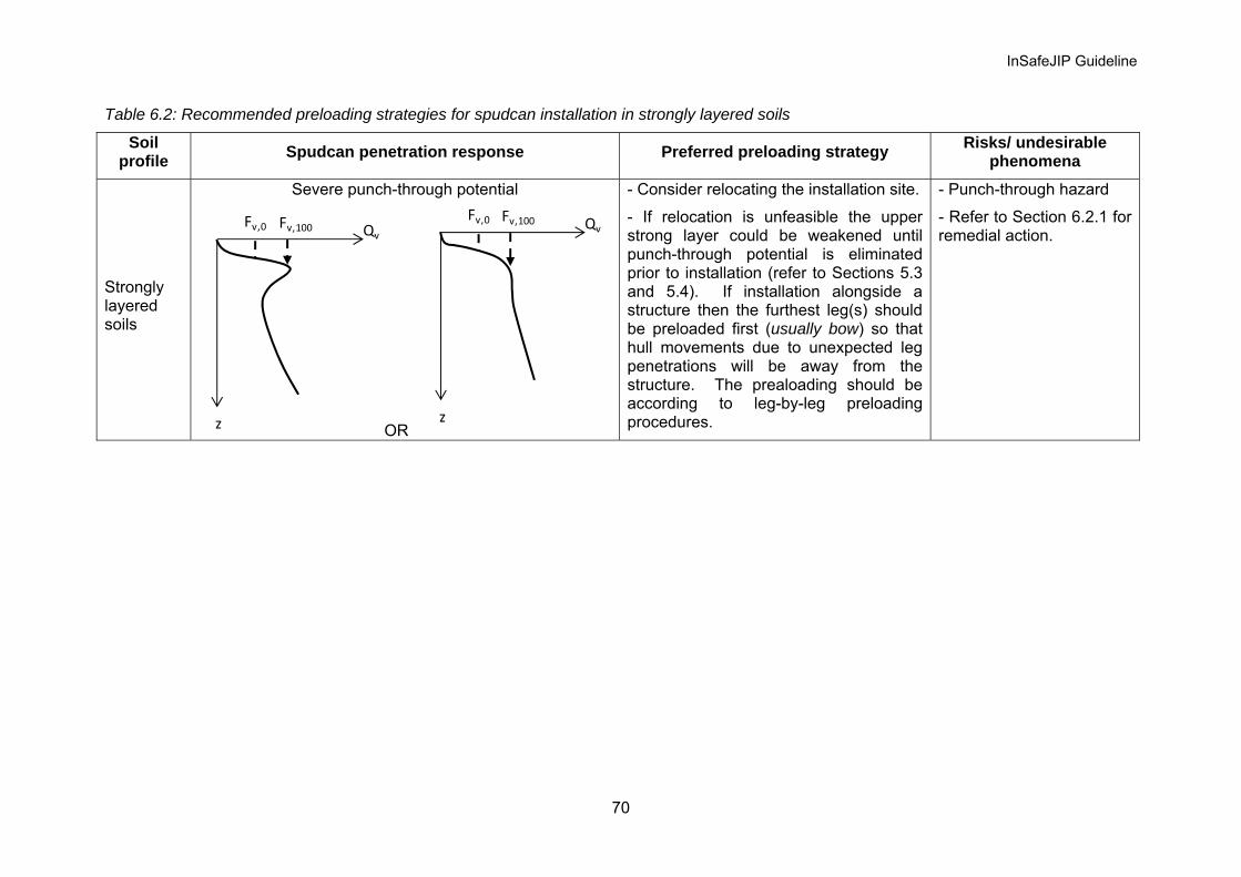
InSafeJIP Guideline
70
Table 6.2: Recommended preloading strategies for spudcan installation in strongly layered soils
Soil profile Spudcan penetration response Preferred preloading strategy Risks/ undesirable
phenomena
Strongly layered soils
Severe punch-through potential
z
Fv,0 QvFv,100
OR
z
Fv,0 QvFv,100
- Consider relocating the installation site.
- If relocation is unfeasible the upper strong layer could be weakened until punch-through potential is eliminated prior to installation (refer to Sections 5.3 and 5.4). If installation alongside a structure then the furthest leg(s) should be preloaded first (usually bow) so that hull movements due to unexpected leg penetrations will be away from the structure. The prealoading should be according to leg-by-leg preloading procedures.
- Punch-through hazard
- Refer to Section 6.2.1 for remedial action.

InSafeJIP Guideline
71
Table 6.2: Recommended preloading strategies for spudcan installation in strongly layered soils (cont.)
Soil profile Spudcan penetration response Preferred preloading strategy Risks/ undesirable
phenomena
Strongly layered soils
Rapid leg penetration / Punch-through potential
z
Fv,0 QvFv,100
OR z
Fv,0 QvFv,100
- An assessment of the controllability of the potential leg plunge during the punch-through in terms of jack-up structural integrity should be considered.
- Sequential preloading with the hull in the water with suitable weather window with minimal wave action is available. Cautious preload application is required as the load approaches the peak bearing resistance. Also be aware of potential set-up effects.
- If installation alongside a structure then the furthest leg(s) should be preloaded first (usually bow) so that hull movements due to unexpected leg penetrations will be away from the structure.
- Ensure that final leg penetrations are such that the spudcans are safely supported in the lower soil layer.
- Rapid leg penetration or punch-through hazard.
- Refer to Section 6.2.1 for remedial action.

InSafeJIP Guideline
72
Table 6.2: Recommended preloading strategies for spudcan installation in strongly layered soils (cont.)
Soil profile Spudcan penetration response Preferred preloading strategy Risks/ undesirable
phenomena
Minimum punch-through potential
z
Fv,0 QvFv,100
OR z
Fv,0 QvFv,100
- Simultaneous preloading with minimum air gap several phases of incrementally increasing load and with longer preload holding time.
- If risk of scouring exists the consequence of scour should be addresses and scour protection installed if necessary (Refer to Section 5.2).
Strongly layered soils No punch-through potential
z
Fv,0 QvFv,100
- Simultaneous preloading with minimum air gap and preload in several phases of incrementally increasing load. Note that the preloading phases may be determined by the combined effects of the rate of load application (which is mainly governed by the water ballast pumping rate), spudcan settlement and tidal conditions
- Avoid/ minimise delay in preloading process
- Susceptible to set-up effect (in clay / silt layers).
- Rapid soil backflow above the spudcan will increase the footing load and could result in rapid footing settlement with effects similar to a punch-through.

InSafeJIP Guideline
73
6.2.1 Remedial action following rapid spudcan penetration Leg runs and punch-throughs usually occur on a single leg at any one time, although occasionally more than one leg may simultaneously suffer such an event. On completion of the punch-through leg settlements the hull may be partially in the water, listing with the legs inclined. The legs will be resisting large bending moments at the hull interaction points, i.e. the guide wear plates and jacking pinions.
Following a punch-through the priority should be to jettison the preload ballast by opening the dump valves. This process is far from instantaneous, however by reducing the hull weight the structural loads will be reduced. During preload dumping a damage survey and assessment should be conducted in order to plan the recovery. Jacking RPD determinations, and wear plate condition evaluations for all legs, i.e. not only the leg which has punched-through, should be conducted at this stage.
If the hull trim significantly exceeds that which is allowable as quoted in the MOM, (i.e. is more than a degree), then jacking should be conducted extremely cautiously in small increments and on no more than one leg at once and only after dumping all preload and anything else that can be dumped. If the hull is in the water then, if possible, it is usually better to jack up on the low side. Simultaneous jacking on both the high and low sides is to be avoided as this may adversely redistribute the leg moments and lead to structural overload and damage. During the recovery jacking the RPD and wear plates should continue to be monitored to avoid overstressing of the leg braces and chords.
Note that the implementation of recovery procedures, following a punch-through, should be carefully planned and executed with expert advice sought where damage may have occurred, or may occur during the recovery process. If inappropriate action is taken during the recovery operation then greater structural damage than caused by the punch-though may result. The recovery plan will depend on the post punch-through situation, the particular jack-up design and possibly other factors.
Where a punch-through has occurred and not all the legs have been forced through the strong layer at the end of the preloading operations then unless the unequal spudcan load – penetration behaviour can be adequately accounted for by the geological model and installation method the safety of the installation will require detailed consideration.
6.3 Operational considerations Following the jack-up installation process, with the hull raised to the required airgap, the legs are locked in position with the brakes applied and / or chocks fitted. During jacked-up operations attention should be given to monitoring the hull level for any foundation settlements which could occur under both ambient and extreme environmental conditions. Due to the magnitude of the settlements individual leg level monitoring is not always practical and often differential leg settlements are identified by the hull inclinometers. Therefore hull inclinations should be maintained within the limits described in the MOM.
For spudcans which are partially embedded or with shallow penetration in granular soils, scour can result in a reduction of the foundation bearing capacity by removal of soil from around and beneath the footings. However, for this to occur the currents, wave action or a combination of both must be severe enough to cause sediment mobility. Minor scour induced settlements are often referred to as “shakedown” and may be accommodated by jacking. However where scour occurs it may be necessary to conduct regular ROV surveys of the foundations, and in extreme circumstances scour prevention, by gravel dumping for example, may be required. Further discussion on this topic is included in Section 5.2.
Foundation settlements under operational conditions may also result from the imposition of cyclic loads generated either environmentally or mechanically.

InSafeJIP Guideline
74
6.4 Spudcan extraction On completion of jack-up operations at a site the hull is lowered into the water and the legs are retracted. The uplift force required to extract the legs from the soil, upliftF , has to exceed
the soil resistance to extraction, or the “breakout force”, breakoutQ , where:
• Uplift force, upliftF - The available force upliftF is governed by the jack-up rack and pinion capacity and hull buoyancy. This value can be established with a high degree of certainty and should be assessed before installation.
• Breakout force, breakoutQ - The spudcan / soil breakout mechanism and therefore the
development of breakoutQ is mainly governed by the spudcan embedment depth, soil type and strength recovery / enhancement of the surrounding soils previously disturbed by the spudcan penetration as a result of re-consolidation.
Leg extraction difficulties can be caused by a range of soil conditions and most commonly occurs where the spudcans are deeply embedded in very soft clays and / or very loose silts. For deeply embedded spudcans in soft clay and / or very loose silts breakoutQ can increase substantially with the length of time the jack-up remains operational at that specific location, mainly due to an increase in the soil strength beneath the spudcan, thereby increasing the reverse end bearing. The use of skirted spudcans in soft clay and loose silt conditions is generally to be avoided as this can result in extremely high resistance to extraction. The assessment of breakoutQ for spudcan extraction in clay is discussed in Section 6.4.1.
The capacity for the jack-up to extract its legs may be assessed prior to installation, where :
Net upliftF > breakoutQ ... (6.4.1)
in which for a given buoyant weight of spudcan, spudW and leg, legW
Net upliftF = Available legspuduplift WWF −− … (6.4.2)
Generic leg extraction procedures are provided in the jack-up’s MOM.
6.4.1 breakoutQ for spudcan extraction in clay
breakoutQ is normally developed after a spudcan has been raised about 0.1 to 0.2 spudcan
diameters from its final penetration, finalh . This depth is termed the “breakout depth”,
breakouth . Depending on breakouth and the cavity depth, ch , the failure plane during a spudcan extraction may extend from the spudcan base to the ground surface (for shallow embedment) or formed locally around the spudcan (for deep embedment). A crude estimation of breakoutQ for different embedment conditions is given in Appendix A6.4.1. Other methods can be used if they can be justified.
When cavitation occurs under high uplift force where the spudcan base is separated from the surrounding soil, maintaining the high uplift force may lead to a brief period of self-

InSafeJIP Guideline
75
accelerating spudcan extraction as during post-peak extraction the resistance continuously decreases but the applied uplift force is (near) constant. The acceleration will decrease as hull buoyancy, and hence uplift, decreases.
Theoretically, spudcan extraction in clayey soils is considered as an undrained process. Partial soil drainage may occur if the spudcan is extracted very slowly, or if there are intermittent pauses during the extraction process. The change in soil drainage can result in soil strengthening as a result of consolidation and thus increasing the resistance to extraction.
Soil with higher strength tends to mobilise a wider failure zone and hence develop a higher
breakoutQ . When the net upliftF is insufficient to facilitate extraction, the pull-out time required may increase logarithmically for unaided extraction method (Lee 1973).
6.4.2 Aided extraction methods for jack-up removal
Where a risk of leg retraction difficulty has been identified i.e. Net upliftF < breakoutQ the standard spudcan extraction procedures may be supplemented with the following :
• Water jetting through spudcan nozzles
• Cyclic loads
• Excavation of the soil present above the spudcan
These methods may reduce breakoutQ by either weakening the soil strength, reducing soil weight or shortening the shear plane, as illustrated in Figure 6.1, and the methods can be applied individually, simultaneously or sequentially.
The success of these methods is variable and much depends on the local ground conditions, the spudcan geometry, system efficiency and experience of the operators. The efficacy of these techniques is discussed further in Table 6.3.

InSafeJIP Guideline
76
Top jetting
Bottom jetting
(a) Water jetting
Soil remoulding
(b) Cyclic loading
Excavation of top soil
(c) Excavation of top soil
Figure 6.1: Aided extraction methods

InSafeJIP Guideline
77
Table 6.3: Aided extraction methods for jack-up removal
Method Specific purpose(s) Recommended practice / Cautions*
Water jetting - Application of pressurised fluid through the spudcan jetting nozzles (upper and / or lower surfaces).
- Base jetting: To reduce the extraction resistance by altering the pore pressure component of the response.
- Top jetting: To loosen the soil present around and on top of the spudcan.
The following comments apply to base jetting.
- The jetting system should be tested prior to contact of the spudcan with the seabed at a location. Clearance of nozzles should be ensured and equal pressure and flow through the nozzles is preferable.
- Early commencement of jetting i.e. when the hull is still at floating draught is recommended.
- Generally jetting at low pressure / high flow rate is recommended. However, high pressure / low flow rate may be applied briefly at the commencement of jetting to ensure the nozzles are unblocked. This is best achieved by a positive displacement pump (e.g. mud pump) where the volume of flow can be monitored and nozzle unblocking can be assured.
- The threshold of hydraulic fracture in the soil provides an upper limit to the jetting pressure that can be applied to assist extraction.
- Jetting has been shown to be beneficial even if negative pore pressures at the spudcan base are not fully eliminated (Bienen et al. 2009).
- The reduction of mobilised negative pore pressure/ generation of positive pore pressure at the spudcan base correlates to the jetting volume. For a given rate of uplift and spudcan area, the achieved jetting volume underneath the spudcan is determined by the jetting flow rate applied. Guidance on the required jetting flow rate for spudcan extraction in normally consolidated clay is provided in Bienen et al. (2009).
- Once breakoutQ is overcome, application of high volume jetting is expected to lead to self-accelerating spudcan extraction.
- Extreme caution is to be exercised when disconnecting pressurised jetting hoses. NOTE: * Compliance of the extraction procedure with the jack-up’s MOM is implicitly assumed.

InSafeJIP Guideline
78
Table 6.3: Aided extraction methods for jack-up removal (cont.)
Method Specific purpose(s) Recommended practice / Cautions*
Cyclic loads – Effect of small amplitude wave loading
- To remould the surrounding soil under cyclic loading conditions
- Could be effective when the leg has shown signs of movement but then suddenly refused such as when engaging a stiffer soil layer impeding its extraction.
- The wave loading should be sufficiently rapid to avoid consolidation and strengthening of the soil around the spudcan.
- A case study, including cautions to this approach, is provided by Erbrich (2005)
Excavation of top soil - Mechanical removal of soil resting on the upper surface of the spudcan.
- To reduce the weight of top soil and shorten the shear plane above the spudcan (Figure 6.1c). However, in all but very deep penetrations or extended periods of jack-up operations this represents a comparatively minor overall contribution to the uplift resistance.
- Access to these materials through the leg well and between the leg members can be difficult.
- The soil excavation method should discharge soil away from the area to avoid subsequent soil slumping and back-filling.
- Soil excavation tool access to the material located above the spudcan is often hindered by the poor access due to the cross braces of the leg truss structure and the vertical inaccessibility due to the hull surrounding the leg. The implementation of top soil excavation is therefore usually challenging and may be of minimal effect.
NOTE: * Compliance of the extraction procedure with the jack-up’s MOM is implicitly assumed.
InSafeJIP Guideline
79
Following leg extraction (with or without aided procedures) the soil within the vicinity of the spudcan and leg when in the ground would have been considerably disturbed and usually a surface expression, in the form of a crater remains. These seabed craters are commonly referred to as “footprints”. The strength of the disturbed soil may vary substantially from the intact strength, however, to determine such soil strength can be complex as the soil may undergo the following phases of shearing and consolidation:
• Shearing during spudcan installation first under full preload then unload to operation load level;
• Consolidation under operational load over the operating period; • Shearing during spudcan extraction (if with aided procedures, the soil will be further
disturbed); • Reconsolidation under self-weight following spudcan removal.
Further, due to the large volume of soil displaced during spudcan installation and extraction, the local soil profile may vary across the disturbed zone in both vertical and lateral directions. In layered soil systems the spudcan installation and removal process can cause the local soil stratigraphy to be modified.
To determine the soil strength profile relevant for subsequent jack-up installation careful consideration should be given to the virgin soil conditions, the effect of the initial jack-up installations on these conditions, the spudcan bearing stresses and respective observed and predicted penetrations. Where there is concern regarding the installation of spudcan over existing footprints additional geotechnical site investigation may be required.

InSafeJIP Guideline
80
List of notations
A = spudcan widest bearing area
effA = effective spudcan bearing area in contact with soil
qB = pore pressure coefficient
CoV = coefficient of variances
D = widest diameter of spudcan/ penetrometer
effD = effective diameter of spudcan in contact with soil
holeD = diameter of the perforation
VF = applied/measured/observed vertical force
0,VF = light-ship load
100,VF = maximum preload
mobF = reduction factor for sand bearing capacity
rF = normalised sleeve friction
upliftF = uplift force
G = shear modulus
DI = relative density
RDI = dilatancy index
rI = rigidity index
sK = punching shear coefficient LL = liquid limit
N = sampling points
ballN = ball factor
breakoutN = breakout factor
cN , γN , qN = bearing capacity factors
cN ' = modified bearing capacity factor
ktN = cone factor
barTN − = T-bar factor
OCR = overconsolidation ratio
InSafeJIP Guideline
81
PL = plastic limit
Q = normalised cone resistance
baseQ = base resistance
breakoutQ = break-out force
crushingQ = crushing strength
bearingendQ − = bearing capacity of the clay column in the underlying clay
shaftQ = shaft resistance of the imaginary stiff clay column
shearQ = shear force mobilised along the failure plane above a spudcan
sideQ = side friction mobilised along the spudcan’s side wall
VQ = vertical bearing capacity
min,VQ = minimum post-peak bearing capacity
peakVQ , = peak bearing capacity
R = spudcan radius
tS = sensitivity
maxT = maximum torsional moment
remT = remoulded torsional moment
V = dimensionless velocity group
CV = volume of spudcan full base
cV = volume of spudcan partially embedded base
soilV = volume of the backfill soil
topV = volume of the spudcan upper can covered by the backflow soil
legW = buoyant weight of leg
soilW = buoyant weight of backflow soil
spudW = buoyant weight of spudcan
a = cone area ratio
a = hyperbolic fitting constant (Appendix A4.7.1 only)
b = hyperbolic fitting constant (Appendix A4.7.1 only)
c = hyperbolic fitting constant (Appendix A4.7.1 only)
'c = apparent cohesion

InSafeJIP Guideline
82
hc = coefficient of consolidation for horizontal drainage
vc = coefficient of consolidation for vertical drainage
d = diameter of penetrometer/ vane blade diameter (only Section 3.3.1.2)
coned = diameter of cone
ed = equivalent diameter of T-bar
basef = factor of strength enhancement due to soil reconsolidation
topf = strength reduction factor to account for soil remoulding
1f = percentage reduction in the periphery of the clay column
2f = percentage reduction in the plan area of the clay column
h = spudcan penetration depth measured from the lowest depth of the maximum plan area / vane blade height (only Section 3.3.1.2)
breakouth = breakout depth
ch = critical cavity depth
columnh = height of soil column remained above a spudcan
crith = depth of peakVQ , , also known as critical depth
finalh = spudcan final penetration during installation
layerh = thickness of upper strong layer
layerh' = effective distance between spudcan base to lower soil layer
neth = net breakout depth (= cbreakout hh − )
plugh = height of sand plug
pth = plunge depth
th = height of spudcan upstand, (upstand height of the widest diameter)
m = constant controlling dilatancy
n = squeezing factor (Section 4.5.2.2)/ number of data point (Section 3.6.1)
1n = number of perforations drilled below the spudcan periphery
2n = number of perforations drilled below the spudcan plan area
rp = pressure (= 1 kPa)
refp = atmospheric pressure i.e. 100 kPa
'p = mean effective stress at failure

InSafeJIP Guideline
83
barTq − = T-bar penetration resistance
cq = measured cone resistance
netq = net penetrometer resistance
drainednetq , = drained net penetrometer resistance
undrainednetq , = undrained net penetrometer resistance
tq = cone resistance corrected for pore pressure effects
us = undrained shear strength of clay
toolus _ = undrained shear strengths measured using the prescribed tool
uas = undrained shear strength averaged over a prescribed distance
ubs = undrained shear strength of the lower clay layer
ubss = surface undrained shear strength of the lower clay layer
uhs = undrained shear strength of clay at depth ch
ums = undrained shear strength at mudline
utops = undrained shear strength of the upper strong clay layer
0us = undrained shear strength at layer surface
baseus , = undrained shear strength of soil beneath a spudcan
plugbaseus , = undrained shear strength corresponding to the level of sand plug base
remus , = remoulded undrained shear strength
sideus , = undrained shear strengths mobilised along th
us = mean undrained shear strength
ums = averaged undrained shear strength at mudline
0us = averaged undrained shear strength at layer surface
2u = pore pressure measured at the cone shoulder
v = spudcan/ penetrometer penetration rate
conev = Cone penetration rate
w = water content
cy = height of the equivalent cone representing the spudcan
my = height of spudcan tip

InSafeJIP Guideline
84
z = distance from sea floor to spudcan tip/ Depth below mudline
finalz = final spudcan tip penetration
z = mean depth
α = spudcan roughness
LPα = load spread angle
β = spudcan cone angle
uΔ = excess pore pressure
γζ h , hqζ = depth factors
sqζ = shape factor
cvφ = critical state angle of friction
φ′ = angle of friction
pkφ′ = peak friction angle
γ ′ = buoyant unit weight of soils
clayγ′ = buoyant unit weight of clay
topclay ,γ′ = buoyant unit weight of top clay
claybγ′ = buoyant unit weight of lower clay
sandγ′ = buoyant unit weight of sand
ρ = undrained shear strength gradient
ρ = averaged undrained shear strength gradient
σ = standard deviation
0vσ = total in-situ vertical stress
n'σ = effective normal stress applied during direct shear test
0'hσ = effective in-situ horizontal stress
0'vσ = effective in-situ vertical stress
τ = Shear stress

InSafeJIP Guideline
85
List of abbreviations
API = American Petroleum Institute
ASTM = American Society for Testing and Materials
BHA = bottom hole assembly
BS = British Standard
C = complex
CAU = anisotropically consolidated undrained triaxial test
CAUC = anisotropically consolidated undrained triaxial compression test
CAUE = anisotropically consolidated undrained triaxial extension test CID = isotropically consolidated drained triaxial test
CIU = isotropically consolidated undrained triaxial test
DS = direct shear (Shear box) test
DSS = direct simple shear
JIP = Joint Industry-funded Project
JU = jack-up rig
MinV = miniature vane
MOM = Marine Operations Manual
MV = motor vane
PP = pocket penetrometer
PSD = particle size distribution
ROV = remotely operated underwater vehicle
RPD = rack phase difference
S = simple
SFI = spudcan-footprint interaction
SI = site investigation
SPI = spudcan-pile interaction
SNAME = Society of Naval Architects and Marine Engineers
TD = target depth/termination depth
TV = torvane
UU = unconsolidated undrained triaxial test
UXO = unexploded ordnance
VC = very complex
WO = work-over

InSafeJIP Guideline
86
References Aas, G., Lacasse, S., Lunne, T. and Høeg, K. (1986). Use of in situ tests for foundation
design on clay. Proc. of the ASCS Specialty Conference In Situ ’86: Use of In situ Tests in Geotechnical Engineering, New York, 1-30.
Barbosa-Cruz, E.R. 2007. Partial consolidation and breakthrough of shallow foundations in soft soil. PhD thesis, The University of Western Australia.
Bienen, B, Gaudin C., Cassidy M.J. (2010). Centrifuge study of the bearing capacity increase of a shallow footing due to preloading. Proc. 7th Int. Conf. on Physical Modelling in Geotechnics (ICPMG), Zurich, Switzerland, Vol. 2, pp. 1019-1024.
Bienen, B., Gaudin, C., Cassidy M.J. (2009). The influence of pull-out load on the efficiency of jetting during spudcan extraction. Applied Ocean Research, Vol. 31, No. 3, 202-211.
Bolton, M.D. (1987). Discussion on The strength and dilatancy of sands. Géotechnique, 37 (2), 219-226.
Bolton, M.D. (1986). The strength and dilatancy of sands. Géotechnique, 36 (1), 65-78.
Borel, D., Puech, A., Dendani, H. and Colliat, J.L. (2005). Deepwater geotechnical site investigation practice in the Gulf of Guinea. Proc. Int. Symp. on Frontiers in Offshore Geotechnics: ISFOG, Perth, London: Taylor and Francis, 921-926.
Brown, J.D. and Meyerhof, G.G. (1969). Experimental study of bearing capacity in layered clays. Proc. 7th Int. Conf. on Soil Mech. and Found. Eng, 2, 45-51.
BS 1377. (1990). British Satandard Methods of Test for Soils and Civil Engineering Purposes. British Standards Institution. London.
Cassidy, M.J. and Houlsby, G.T. (2002). Vertical bearing capacity factors for conical footings on sand. Géotechnique, 52 (9), 687-692.
Cerato, A.B. and Lutenegger, A.J. (2004). Disturbance effects of field vane tests in a varved clay, 2nd Int. Site Characterization Conference, Porto, Portugal, 861-867.
Chandler, R.J. (1988). The in-situ measurement of the undrained shear strength of clays using the field vane. Vane Shear Strength Testing of Soils: Field and Laboratory Studies, ASTM STP 1014, A.F. Richards, Ed., ASTM, Philadelphia, 13-44.
Clarom (1993) Design Guides for Offshore Structures: Stability and Operation of Jackups. Eds.P. Le Tirant, and C. Pérol, Paris: Technip.
Craig, W.H. and Chua, K. (1990). Deep penetration of spudcan foundations on sand and clay. Géotechnique, 40(4), 541-556.
DeGroot, D.J. and Sandven, R. (2004). General report: Laboratory and field comparison, 2nd Int. Site Characterization Conference, Porto, Portugal, Vol. 2, 1775-1789.
De Beer, E. (1967). Bearing capacity and settlement pf shallow foundations on sand. Proc. Symp. On Bearing Capacity and Settlement of Foundations. Dept of Civil Engineering, Duke Univ. Durham, NC, Ed. A. Vesic, 15-43.
Einav, I. and Randolph, M.F. (2006). Effect of strain rate on mobilised strength and thickness of curved shear bands. Géotechnique, 56(7), 501-504.
Erbrich CT. (2005). Australian frontiers – spudcans on the edge. Proc. Int. Symp. on Frontiers in Offshore Geotechnics: ISFOG, Perth, London: Taylor and Francis, 49–74.
Eurocode 7. (2007). Eurocode 7- Geotechnical Design. British Standards Institute. London.

InSafeJIP Guideline
87
Finnie I.M.S. and Randolph M.F. (1994). Punch-through and liquefaction induced failure of shallow foundations on calcareous sediments. Proc. Int. Conf. on Behaviour of Offshore Structures, BOSS '94, Boston, 217-230.
Fleming, W.G.K., Weltman, A.J., Randolph, M. F. and Elson, W.K. (1992). Piling Engineering. Blackie Academic and Professional, Glasgow, 2nd Edit.
Gan C.T., Teh, K. L., Leung, C. F., Chow, Y. K. and Swee, S. (2010). Behaviour of skirted footings in sand overlying clay. Proc. Int. Symp. on Frontiers in Offshore Geotechnics: ISFOG, Perth (in press)
Hanna, A.M. and Meyerhof, G.G. (1980). Design chart for ultimate bearing capacity of foundation on sand overlying soft clay. Can. Geotech. J. 17(2), 300–303.
Hight, D.W. and Leroueil, S. (2003). Characterisation of soils for engineering purposes. Proc. Int. Workshop on Characterisation and Engineering Properties of Natural Soils, Singapore, Vol. 1, Swets & Zeilinger, Lisse, 255-360.
Hossain, M.S. and Randolph, M.F. (2010). Deep-penetrating spudcan foundations on layered clays: numerical analysis. Géotechnique, 60(3), 171-184.
Hossain, M.S. and Randolph, M.F. (2009a). New mechanism-based design approach for spudcan foundations on stiff-over-soft clay. Offshore Technology Conference, OTC19907.
Hossain, M. S. and Randolph, M. F. (2009b). New mechanism-based design approach for spudcan foundations on single layer clay. J. Geotechnical and Geoenvironmental Engineering, ASCE, in press.
Hossain, M.S., M.F. Randolph, Y. Hu and D.J. White. (2006). Cavity stability and bearing capacity of spudcan foundations on clay. Offshore Technology Conference, OTC 17770.
Hossain, M.S., Hu, Y., Randolph, M.F. and White, D.J. (2005). Limiting cavity depth for spudcan foundations penetrating clay. Géotechnique, 55(9), 679-690.
Houlsby, G.T. (2010). A probabilistic approach to the prediction of spudcan penetration of jack-up units. Proc. 2nd Int. Symp. on Frontiers in Offshore Geotechnics: ISFOG, Perth, in press.
Houlsby, G.T and Martin, C.M. (2003). Undrained bearing capacity factors for conical footings on clay. Géotechnique, 53 (5), 513-520.
HSE (UK) (2008). Jack-up (self-elevating) installations: review and location approval using desk-top risk assessments in lieu of undertaking site soils borings. Offshore Information Sheet No 3/2008. http://www.hse.gov.uk/offshore/infosheets/is3-2008.pdf
InSafeJIP (2009). First Year Progress Report, (Final Revision), Unpublished and to remain confidential to the InSafeJIP.
ISSMGE (International Society for Soil Mechanics and Geotechnical Engineering) (1999). ISSMGE Technical Committee TC16 Ground Property Characterisation from In Situ Testing (1999) International Reference Test Procedure (IRTP) for the Cone Penetration Test (CPT) and the Cone Penetration Test with pore pressure (CPTU). Proc., XIIth ECSMGE, Amsterdam. Balkema Pub., 2195–2222.
Jamiolkowski, M.B., Lo Presti, D.C.F. and Manassero, M. (2003) Evaluation of relative density and shear strength of sands from cone penetration test (CPT) and flat dilatometer (DMT), Soil Behaviour and Soft Ground Construction, Eds. J.T. Germain, T.C. Sheahan and R.V. Whitman, ASCE, GSP 119, 201-238.
Kolk, H.J., Hopope, J. and Imms, B.W. (1988). Evaluation of offshore in situ vane test results. Vane Shear Strength Testing of Soils: Field and Laboratory Studies, ASTM STP 1014, 339-353.

InSafeJIP Guideline
88
Kortekaas, S. and Peuchen, J. (2008). Measured swabbing pressures and implications for shallow gas blow-out. Offshore Technology Conference, OTC19280.
Kulhawy, F.H., and Mayne, P.W. (1990). Manual on estimating soil properties for foundation design. Report EL-6800, Electric Power Research Institute, Palo Alta, CA, August, 306.
Lacasse, S., Guttormsen, T., Nadim, F., Rahim, A. and Lunne, T. (2007). Use of statistical methods for selecting design soilparameters. Proc. 6th Int. Offshore Site Investigation and Geotechnics Conference: Confronting new challenges and sharing knowledge, 11-13 September 2007, London, UK, 449-460.
Ladd, C.C. and DeGroot, D.J. (2003). Recommended practice for soft ground site characterization: Arthur Casagrande Lecture. 12th Panamerican Conf. on Soil Mechanics and Geotechnical Engineering, Massachusetts Institute of Technology, USA.
Lee, H.J. (1973). Breakout of partially embedded objects from cohesive seafloor soils. Offshore Technology Conference, OTC1904.
Lee, K. K. (2009). Investigation of potential spudcan punch-through failure on sand overlying clay soils. PhD. Thesis, The University of Western Australia, Perth.
Lee, K. K., Randolph, M.F. and M.J. Cassidy (2009). New simplified conceptual model for spudcan foundations on sand overlying clay soils. Offshore Technology Conference, OTC 20012.
Low, H.E., Lunne, T., Andersen, K.H., Sjursen, M.A., Li, X. and Randolph, M.F. (2010). Estimation of intact and remoulded undrained shear strength from penetration tests in soft clays. Géotechnique, in press.
Lunne, T., Tjelta, T.I., Walta, A. and Barwise, A. (2008). Design and testing out of deepwater seabed sampler. Offshore Technology Conference, OTC 19149.
Lunne, T. and Andersen, K.H. (2007). Soft clay shear strength parameters for deepwater geotechnical design, Proc. 6th Int. Offshore Site Investigation and Geotechnics Conference: Confronting new challenges and sharing knowledge, 11-13 September 2007, London, UK.
Lunne, T., Robertson, P.K., and Powell, J.J.M. (1997). Cone penetration testing in geotechnical practice. London: Blackie Academic and Professional.
Mayne, P.W., Christopher, B.R. and DeJong, J. (2001). Getechnical Site Characterization. Manual on Subsurface Investigation, National Highway Institute, Publication No. FHWA NHI-01-031, Federal Highway Administration, Washington, DC.
Merifield, R.S. and Nquyen, V.Q. (2006). Two- and three-dimensional bearing capacity solutions for footings on two-layered clays. Int. Journal of Geomechanics and Geoengineering, 1(2), 151-162.
Meyerhof, G.G. and Hanna, A.M. (1978). Ultimate bearing capacity of foundations on layered soils under inclined load. Canadian Geotechnical Journal, 15(4), 565-572.
Meyerhof, G.G. and Chaplin, T.K. (1952). The compression and bearing capacity of cohesive layers. British Journal of Applied Physics, 4:20.
NORSOK Standard (2004). “Marine soil investigations” G-001, Rev. 2, October 2004.
Oil and Gas UK (formerly Offshore Operators Association Limited, Surveying & Positioning Committee). (1997). Guidelines for the Conduct of Mobile Drilling Rig Site Surveys, Volume 1 Issue 1.2. and Volume 2 Issue 1.
Osborne, J.J. and Paisley, J.M. (2002). SE Asia jack-up punch-throughs: The way forward? Proc. Int. Offshore Site Investigation and Geotechnics Conference, London, 301-306.

InSafeJIP Guideline
89
Paisley, J.M. and Chan, N. (2006). SE Asia punch-throughs: Technical guidance note on site assessment. 1st Jack-up Asia Conference and Exhibition, Singapore.
Perkins, S.W. and Madson, C. (2000). Bearing capacity of shallow foundations on sand: A relative density approach. Journal of Geotechnical and Geoenvironmental Engineering, 126 (6), 521-530.
Peuchen, J., Adrichem, J. and Hefer, P.A. (2005). Practice notes on push-in penetrometers for offshore geotechnical investigation, Proc. Int. Symp. on Frontiers in Offshore Geotechnics: ISFOG, Perth, London: Taylor and Francis.
Phoon, K.K. and Kulhawy, F.W. (1999). Characterisation of geotechnical variability. Can. Geotech. J., 36, 612-624.
Purwana, O.A., Quah, M., Foo, K.S., Nowak, S. and Handidjaja, P. (2009). Leg extraction/pullout resistance – theoretical and practical perspective. Proc. 12th Int. Conf. The Jack-up Platform – Design, Construction and Operations, 15-16 September 2009, London.
Purwana, O.A., Leung, C.F., Chow, Y.K. and Foo, K.S. (2005). Influence of base suction on extraction of jack-up spudcans. Géotechnique, 55(10), 741-753.
Quiros, G.W., Young, A.G., Pelletier, J.H. and Chan, J. H-C. (1983). Shear strength Interpretation for Gulf of Mexico Clays, Proc. Conf. on Geotechnical Practice in Offshore Engineering, Austin, April, 144-165.
Randolph, M.F. (2004). Characterisation of soft sediments for offshore applications, 2nd Int. Site Characterization Conference, Porto, Portugal, Vol. 1, 209-232.
Randolph, M.F. and Hope, S. (2004). Effect of cone velocity on cone resistance and excess pore pressure. Proceedings of International Symposium on Engineering Practice and Performance of Soft Deposits, Osaka, 147-152
Randolph, M.F., Jamiolkowski, M.B. and Zdravkovi, L. (2004). Load carrying capacity of foundations. Proc. Skempton Memorial Conf., London, Vol. 1, 207-240.
Randolph, M.F., Hefer, P.A., Geise, J.M. and Watson, P.G. (1998). Improved seabed strength profiling using T-bar penetrometer. Proc. Int. Conf. Offshore Site Investigation and Foundation Behaviour - "New Frontiers", Society for Underwater Technology, London, UK, 221-236
Robertson, P.K. (1990). Soil classification using the cone penetration test. Can. Geotech. J., 27(1),151 – 158.
Salgado, R., Bandini, P. and Karim, A. (2000). Shear strength and stiffness of silty sand. Journal of Geotechnical and Geoenvironmental Engineering, ASCE, 126(5), 451- 462.
Schnaid, F., Lehane, B.M. and Fahey, M. (2004). In situ test characterisation of unusual geomaterials, 2nd Int. Site Characterization Conference, Porto, Portugal, Vol. 1, 49-73.
Schneider, J.A., Randolph, M.F., Mayne, P.W. and Ramsey, N.R. (2008). Analysis of factors influencing soil classification using normalized piezocone tip resistance and pore pressure parameters. Journal of Geotechnical and Geoenvironmental Engineering, ASCE, 134(11), 1569-1586.
Schneider, J.A., Lehane, B.M. and Schnaid, F. (2007). Velocity effects on piezocone measurements in normally and overconsolidated clays. Int. Journal of Physical Modelling in Geotechnics, 7(2), 23-34.
SNAME (Society of Naval Architects and Marine Engineers). (2008). Recommended practice for site specific assessment of mobile jack-up units, SNAME Technical and Research Bulletin 5-5A, Rev. 3, New Jersey.

InSafeJIP Guideline
90
Sweeney, M.S., Webb, R.M. and Wilkinson, R.H. (1988). Scour around jackup rig footings. Offshore Technology Conference, OTC 5764.
Teh K. L. (2007). Punch-through of spudcan foundation in sand overlying clay. Ph.D thesis, National University of Singapore, Singapore.
Teh, K. L, Leung, C. F, Chow, Y. K. and P. Handidjaja (2009). Prediction of punch-through for spudcan penetration in sand overlying clay. Offshore Technology Conference, OTC 20060.
Teh, K. L, Leung, C. F., Chow, Y. K. and Cassidy, M.J. (2010). Centrifuge model study of spudcan penetration in sand overlying clay. Géotechnique, in press.
Teh, K. L., Gan, C. T., Hu, E. H. J., Leung, C. F. and Chow, Y. K. (2008). A comparison of penetration behaviour of spudcan and skirted footing in sand overlying clay, Proc. 2nd Jack-Up Asia Conference & Exhibition, Singapore.
Terzaghi, K., Peck, R.B. and Mesri, G. (1996). Soil Mechanics in Engineering Practice, John Wiley & Sons, Inc., New York, 729.
Trevor, F.A. and Mayne, P.W. (2004). Undrained shear strength and OCR of marine clays from piezocone test results, 2nd Int. Site Characterization Conference, Porto, Portugal, Vol. 1, 391-398.
Uzielli, M., Lacasse, S., Nadim, F. and Phoon, K.K. (2006). Soil variability analysis for geotechnical practice. 2nd Int. Workshop on Characterisation and Engineering Properties of Natural Soils. Singapore, The Netherlands: Taylor and Francis.
Vesic, A. S. (1975). Bearing capacity of shallow foundations. In “Foundation Engineering Handbook” (ed. H. F. Winterkorn and H. Y. Fang), 121-147. New York: Van Nostrand.
Watson, P.G and Humpheson, C. (2005). Geotechnical interpretation for the Yolla A platform. Proc. Int. Symp. on Frontiers in Offshore Geotechnics: ISFOG, Perth, London: Taylor and Francis, 343–349.
White, D.J., Teh, K.L., Leung, C.F. and Chow, Y.K. 2008. A comparison of the bearing capacity of flat and conical circular foundations on sand. Géotechnique 58 (10), 781-792.
Yi, J.T., Goh, S.H., Lee, F.H. and Randolph, M.F. (2009). A numerical study of cone penetration rate effects. (paper under review).
Yoon, Y. (1991). Static and Dynamic Behaviour of Crushable and Non-Crushable Sands. Ph.D Thesis, Ghent University.
Zdravković, L., Potts, D.M. & Jackson, C. 2003. Numerical study of the effect of preloading on undrained bearing capacity. International Journal of Geomechanics (ASCE) 3, 1-10.
Zhou, H. and Randolph, M.F. (2009). Resistance of full-flow penetrometers in rate-dependent and strain-softening clay. Géotechnique, 59(2), 79-86.

InSafeJIP Guideline
91
Appendices

InSafeJIP Guideline
92
Appendix A2 Appendix A2.1.1: Geotechnical SI planning – Geohazards The geohazards associated with jack-up rig installations reported by SNAME (2008) are discussed below in no particular order :
(a) Adverse shear strength profiles – these are profiles which can result in rapid and uneven spudcan penetration behaviour, and they normally feature one of the following :
• strongly layered systems
• constant shear strength with depth
• weakly increasing shear strength with depth
• decreasing shear strength with depth
Strongly layered systems can also be formed by a stiff over soft clay sequence, with the stiff material being the result of sub-aerial exposure and desiccation which, for example, is a common feature in the Sunda Shelf, in Southeast Asia.
A thick layer of soft soil with either constant shear strength or weakly increasing strength with depth can also be problematic for jack-ups as leaning instability can follow differential spudcan settlement.
Rapid spudcan penetration can occur if the rate of bearing capacity increase is inadequate to resist the rate of loading increase, imposed by the shift of the toppling structure’s centre of gravity. The vertical bearing capacity of the settling leg may also be degraded as lateral and moment loads are applied as the structure topples.
A sudden increase in footing load caused by the collapse of soil on top of the spudcan could also lead to jack-up instability and result in adverse footing penetration.
Any such resulting rapid leg penetration which occurs such that the hull trim cannot be maintained within its allowable limits by jacking may be described as a “punch-through”. Punch-through failure is possibly the most hazardous of all the geohazards for jack-up foundations, and is responsible for more than half the events accounting for loss of life, injury, structural damage etc.
The potential of foundation failure due to adverse shear strength profiles should be identified during the geotechnical site investigation and considered during the site assessment prior to jack-up installation.
(b) Jack-up footprints - The creation of jack-up footprints on the seabed can present a hazard for future jack-up operations particularly if the foundation geometry of the new jack-up is incompatible with the unit initially installed. Incompatible spudcan-footprint-interaction (SFI) can cause adverse spudcan displacement resulting in an inability to install the jack-up in the required position, leg splay (inwards and outwards), unacceptable rack phase difference (RPD) and at worst structural damage. Geophysical techniques such as sidescan sonar and multibeam echosounder can be used to generate images of existing footprints (provided they have not become fully backfilled and their surface expression obscured) which can then be assessed in order to evaluate the risks associated with subsequent jack-up emplacement.
(c) Spudcan extraction – Extraction of spudcan leg(s) can be problematic due to the following :
- Deep penetration beyond a given specification within the jack-up manual
- Spudcan embedded below a thick crustal material or penetrated deeply into a thick layer of silt or a partially drained stratum
- Extended period of operation time

InSafeJIP Guideline
93
- The use of inappropriate spudcan design in soft soil conditions (for example caisson footings with inadequate jetting systems)
- Footing loaded at close to maximum preload pressure over a substantial period of time in which case the soil underneath the spudcan is strengthened significantly
More discussion on spudcan extraction is given in Section 6 of the Guideline.
(d) Seabed mobility (sand wave migratory field) and scour – These geohazards are broadly confined to comparatively shallow waters with significant currents, and perhaps wave induced water velocities, which create bed shear of adequate strength to mobilise granular soils. The most obvious surface expression of mass soil mobility is a sand wave field. Locating jack-ups on mobile sediments, particularly sand waves, is generally to be either avoided, or designed for by the use of scour prevention methods.
For a surface supported spudcan on granular soil the imposition of such a seabed obstruction will induce locally increased current flow, which can result in localised material mobilisation. Where this results in a net removal of soil scour pits will develop and material removal from around and beneath a spudcan will reduce the soil bearing capacity. Therefore the scour process can affect the foundation stability especially where the surface sand upon which the spudcan may be founded is underlain by a weaker material.
With partial undermining of a spudcan by scour high concentration of eccentric loads can occur which can affect the structural integrity and foundation stability.
The change in seabed condition can be checked by divers or using multibeam echosounders and sidescan sonar, although the worst scour condition is likely to occur at the height of a storm, at which point it is unlikely that it would be possible to survey the excavation, which may be expected to partially infill as the storm abates. (e) Ground instability (mass down-slope movement) - Subsea landslides may constitute a geohazard for jack-ups. The size of subsea landslides can range from small and superficial drape slides to colossal down-slope mass movements. As a consequence an understanding of the seabed morphology and geology for a large area should be acquired when assessing an area for a jack-up installation. Desk studies should provide an idea of the risk presented by land sliding allowing the site investigation to be designed with the presumed risk addressed. Geophysical surveys such as the multibeam echosounder or sidescan sonar can be used to assess the potential for mass sediment failure by flow and / or sliding.
Geotechnical borehole analysis and soil testing, together with piezometer installation can also be used to assess the potential for soil mass instability. Age dating can also be useful in understanding the history of slope instability over an area of development interest.
(f) Seabed obstructions (manmade or natural) - Environmental obstructions include coral, outcrops and protected habitats which are under legislation such as 92/43/EEC on the conservation of natural habitats; and of wild fauna and flora which designates areas into annexes depending on the level of protection and conservation. The implication of locating a jack-up rig at an Annex 1 habitat is serious and should not be overlooked. Grab samplers and underwater cameras can be used to identify seabed obstructions.
Human debris and artefacts are commonly found on the seabed where human activity is greatest and they include: borehole cutting mounds, drilling grout spills, pipelines, cables and wrecks as well as UXO, (and dumped materials such as rubber tyres, concrete blocks, ladders, fenders, umbilicals, cables, fibre optics etc). Human debris is often metallic and identifiable by magnetometer and perhaps sidescan sonar survey if present on the surface.
(g) Sloping strata (seabed or buried) and infilled channels - Sloping strata can cause a sliding hazard for jack-ups as during initial loading the legs could slide downslope which may result in structural damage (unacceptable RPD etc).

InSafeJIP Guideline
94
In the worst case the legs could splay to such a degree that they become jammed in the guides, causing a “bind” situation where the jacking system is unable to move the hull on the legs.
The angle at which sloping strata may become a problem is site specific. However, as a general guidance, a seabed gradient of greater than 2° to 4° would be more commonly regarded as the upper limit before one should consider the potential for leg sliding or eccentric foundation support.
Sub-bottom profilers can be used to determine the dip and strike of the soil layers and this can be interpreted in association with geotechnical data during development of the ground model.
The presence of paleochannels or infilled ice gouges could also be hazardous to the rig installation when one or two legs are installed in the infilled area whereas the remaining leg(s) is in non-infilled ground. The infilled area normally contains unconsolidated (or less consolidated) sediments than the surrounding soils. Channel infill re-worked materials can be extremely variable and lead to large differential leg penetrations. Emplacement of leg(s) within infilled channels and at the steep shoulders should generally be avoided.
(h) Foundation overload – Foundation overload can occur during ultimate storm conditions where the loads and displacements exceed allowable limits.
If the jack-up site specific operability assessment has been suitably conducted then this situation should not theoretically arise.
(i) Other hazards - Other hazards include jacking delays, alteration of foundation soils after the initial visit, insufficient leg length, shallow high pressure venting gas (or loss of well control) that undermines the foundation soils, adverse spudcan-pile, spudcan-pipeline interaction etc. Although these situations may be potentially hazardous to safe jack-up installation, operation and / or removal, they are not discussed further here.

InSafeJIP Guideline
95
Appendix A2.4.1: Geotechnical sampling - Sample disturbance and precautions
Sample disturbance affects the determination of strength parameters. Unless laboratory strength testing is performed on high quality samples it will not be representative of in-situ soil behaviour (Lunne et al. 2008). The main causes of sample disturbance are (Lunne and Andersen 2007) :
1. Soil disturbance due to the drilling process.
2. Disturbance introduced by pushing the sample tube into the soil.
3. Stress relief as the sample is brought up to deck (especially if gas is present in-situ).
4. Handling, storing and transportation of the sample to an onshore laboratory.
5. Laboratory testing equipment and procedures.
Heave compensation of the drilling and sampling equipment (preferably by a “hard-tie” system) is crucial to minimise sample disturbance, ensuring that the drill string is not reciprocated unduly or unintentionally relative to the undisturbed soil. Such motions disturb the soil ahead of the drill bit and limit the ability to acquire high quality samples. Experienced drillers are able to minimise the downhole soil disturbance by the control of bit weight, rotational velocity, flush pressure and flow rate during bit penetration and hole cleaning operations.
Offshore geotechnical drilling spreads typically comprise open flush rotary systems with an over-bored API 5” drill string through which sampling and testing systems are deployed. The tools may be run-in by wireline or umbilical and latch in to the bottom hole assembly (BHA). The drill bit is attached to the base of the BHA, above which are weighted collars with joints of pipe above.
Each specialist geotechnical drilling vessel carries a range of sample tubes for soil sampling, with the most common being the thin walled “Shelby tube” which consists of a thin-walled steel tube whose lower end is chamfered to form a cutting edge. The area ratio is approximately 10% with standard 76.2 mm external and 72.9 mm internal diameters. The maximum tube lengths are typically in the order of 1 m, with the top 100 mm being used for fixing the tube to the drive head. Shelby tubes can provide high quality undisturbed samples in soft to stiff cohesive soils, including sensitive clays, provided that the soil has not been disturbed by the drilling process.
The quality of samples obtained with tube samplers depends on the geometry of the sampler (DeGroot and Sandven 2004, Hight and Leroueil 2003), with influences including sharp cutting shoe, minimal inside friction, an area ratio smaller than 17%, and constant velocity penetration.
Hydraulically driven Shelby piston tube samplers are generally considered to be of the highest quality achievable when using downhole drilling equipment.
Shelby tubes may be unable to retain clean granular soil samples and some operators use modified tubes with core catcher systems which create greater soil disturbance but increase the probability of acquiring soil samples. In harder ground percussive sampling or perhaps rotary (piggy-back) coring systems may be employed. Percussive sampling systems generally provide highly disturbed, low quality samples.
Once the sample tube is recovered to deck it is taken to the soil laboratory, where the sample ends are cleaned and inspected. If the soil at the bottom of the sample tube is identified as a clay, and where granular inclusions are not expected, then a laboratory motor-vane test may be conducted.
If this test is not conducted, or following the test, the soil is extruded from the sample tube by an hydraulic actuator, preferably in the direction in which it was sampled in order to maintain

InSafeJIP Guideline
96
the stress regime present within the sample, as opposed to reversing it and causing additional disturbance. Often it may not be possible to extrude the soil in the preferred direction due to the extruder assembly design.
On extrusion the soil sample is carefully inspected with any soil cuttings removed from the top of the sample and excess drilling fluid, if present, removed. The length of the sample is then measured, photographed and described by a trained soil technician, geologist or geotechnical engineer. At this stage it is important to note whether there are any obvious signs for interstitial gas expansion in the form of sample expansion, or the opening of expansion cavities, or gas blister on the sample external skin.
It may be possible to identify obviously disturbed soil within the sample, and if present this is likely to be within the upper section. The zone of disturbed soil will extend below the last (nominal) depth of drilling (Lunne and Andersen 2007). Soil within this section may be useful for descriptive purposes but caution should be exercised when interpreting the results of soil tests when they are conducted on disturbed materials.
Lengths of sample are selected for laboratory testing, with undisturbed clay samples being cut in lengths of approximately 150 to 180 mm lengths for either UU testing offshore, or preserved in clingfilm, wrapped in aluminium foil, and then placed in cardboard tubes with the annulus usually filled with molten paraffin wax. The preserved samples are taken to an onshore laboratory for additional testing.
For specific engineering applications, such as detailed cyclic soil testing for example, samples may be sealed in the sample tubes and extruded onshore following examination by unobtrusive methods, for example by X-Ray photography, although this procedure is currently seldom, if ever, conducted for jack-up site investigations. X-raying the sample before extruding the sample allows for the detection of potential disturbed zones (cracks, remoulding etc) before opening the liner and allows selection of representative samples for laboratory strength testing (Borel et al. 2005).

InSafeJIP Guideline
97
Appendix A2.4.2: Geotechnical field testing – Offshore cone penetration tests
In the cone penetration test a conical penetrometer is pushed into the soil at a constant rate. Typical dimensions of the cone are an apex angle of 60° and a diameter of 35.7 mm (giving a cross-sectional area of 10 cm2) with a 150 cm2 friction sleeve. Most offshore cone testing nowadays incorporate a pore pressure sensor (so-called piezocone), with the most common location for pore pressure measurement being the cone shoulder ( 2u position, see Figure A2.4.2.1). The standard rate of penetration is 20 mm/s (ISSMGE 1999). In downhole mode, the test is conducted in pushes of, typically, 1m, 2 m or 3 m to a maximum of 4.5 m strokes; the cone equipment is then recovered to deck and the zone disturbed by the cone is then drilled out. After that a further piezocone test may be conducted, or alternatively a sample may be taken. Piezocone testing strokes of only 1 m are to be discouraged, and 3 m (or greater) is recommended, as this minimises the loss of data between pushes, and the effects of disturbance during drilling. Whilst the test procedure is reasonably straightforward it does require strict adherence to the specification as otherwise the success of the test may, to some degree, become operator dependent (provided of course that the mechanical system is reliable).
Figure A2.4.2.1: Terminology for piezocone (Lunne et al. 1997)
(a) Assessment of quality
Zero readings should be taken (and reported) before and after a piezocone test, with the cone on deck prior to running down the drill string, with the tip just above the soil and the load cells being allowed to stabilise at the ambient temperature, and following the test at the BHA, and again when returned to deck. Changes in the zero reading, referred to as zero drift, arise from changes in temperature and other influences and need to be taken into account when analysing the data (Peuchen et al. 2005, referencing ISSMGE 1999). Effects of zero drift are generally only significant in soft clays, with strengths below 30 kPa, but it should be borne in mind that most piezocone tests conducted offshore only guarantee Class 3 accuracy, which allows up to 400 kPa error in the cone resistance (NORSOK 2004).
(b) Cone size
Although the standard cone tip area is 10 cm2, the larger 44 mm diameter (15 cm2) cone is becomingly increasingly popular, and cone sizes of 25 mm (5 mm2) to 50 mm (20 cm2) are permitted in guidelines. In addition, mini-cones of 15 mm diameter (1.75 cm2) are occasionally used, pushed continuously from the seabed to depths of up to about 10 m (Watson and Humpheson 2005). Reasons for variation in the net cone resistance deduced from tests using different cone sizes include :

InSafeJIP Guideline
98
• Accuracy of correction for pore pressure acting on the back of the cone, with the correction typically increasing (and becoming less accurate) for the smaller the cone size.
• Minor variations due to different strain rates (proportional to penetration rate, conev ,
divided by cone diameter, coned ).
• Effects of soil structure (grain size, uneven cementation, silt lenses, fissures), which will tend to increase the cone resistance as the cone size reduces.
• Partial consolidation, a function of vconecone cdv / , where vc is the consolidation coefficient, which can also lead to increased cone resistance as the cone size reduces.
These effects have been discussed in relation to platform design and spudcan penetration prediction by Watson and Humpheson (2005) and Erbrich (2005).
(c) Pore Pressure Measurement
Pore pressure measurement in cone tests should be standard for the following reasons:
• Pore pressure measurement enhances the profiling capability of the cone penetrometer, allowing identification of soil type in each layer (Schnaid et al. 2004).
• Pore pressure affects the cone resistance measurement because it acts on the outer annulus of the back of the cone, reducing the resistance measured by the load cell. It is vital that the cone tip resistance cq should be corrected for pore pressure effects to allow accurate soil characterisation, and that site investigation reports provide corrected (total) cone resistance, tq . The net cone resistance, netq is then obtained by subtracting the overburden stress.
• Pore pressure measurements allow the evaluation of drainage conditions during penetration, including identification of partial drainage in intermediate soils (Schnaid et al. 2004), using the non-dimensional parameter vcvdV /= (Finnie and Randolph 1994). This will aid the correct assessment of representative soil parameters. Intermediate soils are typically characterised by an increase in penetration resistance (due to partial consolidation) but a decrease in excess pore pressure ratio, qB , and unless partial drainage is detected, the undrained shear strength of the soil can be significantly overestimated with serious consequences for bearing capacity (load-penetration) predictions (Randolph 2004, Erbrich 2005, Schneider et al. 2008).
The main advantages of cone penetration testing are the continuous resistance profile that is achieved, elimination of sample disturbance effects and the extensive experience for interpretation of soil type and estimating soil parameters from correlations (Lunne and Andersen 2007). Contrary to other published advice (e.g. Borel et al. 2005) it is not recommended to perform discontinuous piezocone penetration tests alternating with soil sampling (or strength testing using other methods) which may result in large degree of disturbance, and therefore scatter and uncertainty, introduced to those alternative shear strength measurements. Ideally, Lunne and Andersen (2007) recommend the use of two continuous profiling methods, such as for example the piezocone and the T-Bar or Ball (see later) tests, to evaluate the shear strength, however, this is infrequently plausible for jack-up geotechnical site investigations where dedicated geotechnical drilling spreads are typically used, and for which T-Bar tests cannot currently be conducted within a 5” API drill string (note that piezocone and Ball penetrometer tests can be conducted with a 5” API drill string).

InSafeJIP Guideline
99
The advancing piezocone test anticipates the effect of a weaker or stronger layer below before the cone tip enters the layer, and needs significant penetration (5 to 10 diameters) into a new layer before it reaches a steady state resistance.
By contrast, the cone friction sleeve will measure the average friction of the material as it passes through it. This measurement may therefore be helpful in defining layer boundaries. However, the low reliability of friction sleeve data (refer to Section 3.2) should be borne in mind.
(d) Dissipation tests
In sediments containing a significant proportion of silt, dissipation tests can be conducted in order to estimate the consolidation coefficient of the soil, and hence estimate (from the normalised velocity, V ) whether the cone test is likely be influenced by partial consolidation. Intermediate or partially drained soils can be identified by reference to the normalised cone resistance, 0'/ vnetq σ and pore pressure coefficient, netq quB /Δ= , or the excess pore
pressure ratio, 0'/ vu σΔ .
When dissipation tests are conducted they are normally performed at the end of individual strokes in the soil layer of interest. The change in pore pressure is measured until at least 50% of consolidation is achieved. While dissipation tests do not provide reliable estimation of
vc (strictly the consolidation coefficient for horizontal drainage, hc ) in partially drained soils
(Schneider et al. 2007), it is still helpful to consider the 0'/ vnetq σ , as a function of V , in order to identify zones where partial consolidation may have affected the cone resistance. This would allow correction for partial consolidation to be performed on the cone resistance before it is used to derive undrained shear strength. The non-dimensional groups qB or 0'/ vu σΔ are also useful in that regard (see Randolph 2004). However, these tests are not currently conducted during jack-up geotechnical site investigation partly because it requires longer testing time particularly in clay, and additionally few contractors are able to perform them. In fact, the testing time to reach 50% of consolidation in intermediate soils (with hc = 100 to 10,000 m2/yr) is reasonably short i.e. < 10 min (Mayne et al. 2001). This test duration is estimated for a 10 cm2 piezocone with the pore pressure measurement located at the cone shoulder, which penetrates into soil with rigidity index ranging from 20 to 500. Therefore, in areas where partially drained soils are known to be potentially problematic for jack-up foundations dissipation tests could be conducted and the data would provide valuable information for bearing capacity prediction and assessment of installation options. The data is also useful for jack-up leg extraction.

InSafeJIP Guideline
100
Appendix A2.4.3: Geotechnical field testing – full-flow penetrometer penetration tests
In the last decade, the use of full-flow penetrometers such as the cylindrical T-bar, and spherical ball penetrometer, has increased particularly in deepwater sites, generally supplementing cone testing (Randolph et al. 1998, Lunne et al. 2005). Although they are seldom employed during jack-up geotechnical site investigations for reasons previously cited, these devices offer potential advantages over the cone :
• Minimal correction for pore pressure and overburden stress, and also a higher signal (change in resistance) relative to the hydrostatic head; both of these are due to high area ratio, with the projected area of the penetrometer being typically 10 times that of the shaft.
• Flow mechanisms that are more amenable to analysis and hence theoretically based resistance factors from which to deduce the shear strength of the soil; current solutions allow for the effects of strain rate and softening of the soil (Zhou and Randolph 2009).
• Monitoring of the penetrometer resistance during extraction provides an estimate of the soil sensitivity, and also indicates any potential zero drift of the load cell; in principle the same could (and should) be done with a cone penetrometer, but is seldom, if ever, done.
• Cyclic penetration and extraction tests allow the remoulded penetration resistance to be measured, hence allowing estimation of the remoulded shear strength of the soil and its sensitivity. This has direct application to spudcan penetration calculations.
A joint industry project was undertaken jointly between the Norwegian Geotechnical Institute and the Centre for Offshore Foundation Systems, reviewing the use of in situ penetrometer tests (cone, T-bar and ball) for estimating intact and remoulded shear strengths in soft sediments (Low et al. 2010). The recommended resistance factors are summarised in Section 3.3.1.1.

InSafeJIP Guideline
101
Appendix A2.4.4 Geotechnical field testing – In-situ vane tests
In-situ vane tests (also referred to as remote vane tests) may be conducted using a downhole tool or, at shallow depths, from a seabed rig. Unlike the continuous profile obtained from a penetrometer, in situ vane testing only provides strength measurements at discrete depths.
There are several sizes of in-situ vane with diameters ranging from 38.1 to 65 mm. The most commonly used in-situ vane is 65 mm in diameter and 130 mm high, with net area ratio of around 9 to 11% and perimeter ratio of 3 to 4%. Shear strength measurements are affected by the thickness of the vane blades due to the related disturbance (Cerato and Lutenegger 2004). The standard penetration rate shall not exceed 25 mm/s, after which a waiting times of 2 to 5 minutes is applied before the vane is rotated at 0.1 or 0.2°/s (NORSOK 2004). The testing procedure in a vane test is important as the strength measured is sensitive in particular to the wait period before rotation as well as the rotation rate (Chandler 1988), with potential overestimation of undrained shear strength in silty soils due to rapid consolidation following insertion of the vane. Offshore in-situ vane shear measurements are not usually corrected at all, which differs from onshore practice (Aas et al. 1986, Kolk et al. 1988, Randolph 2004). Some possible reasons for this deviation include (i) some reported offshore cases where the us measured by McClelland remote vanes were found comparable to those measured by miniature vane and UU on 3-inch pushed samples (Quiros et al. 1983); (ii) the net effect of plasticity index PI on the vane shear measured shear strength may not exist (Terzaghi et al. 1996, Mayne et al. 2001); and (iii) the insertion of some offshore vanes which are operated by offline system inherently causes soil disturbance, producing a measured us value that is lower than the actual one (Randolph 2004). However, reasons (i) and (ii) may be valid only for the specifically mentioned marine sediments and loading conditions.
Vane tests are commonly used to estimate the remoulded shear strength and hence the sensitivity, tS , for the soil. The knowledge of remoulded shear strength is useful for the design of jack-up revisit. However, current offshore equipment is not designed to allow rapid rotation of the vane for 10 revolutions at a rate ≥ 4 rev/min recommended to remould the soil before measuring the remoulded strength (NORSOK 2004). Instead, the common offshore practice involves determination of peak and remoulded shear strengths from a continuous measurement of torque-rotation curve. For a full vane shear test which includes rotation at 0.2°/s from 0° to 90°, remoulding over 180° at 0.6°/s and the remoulded/ residual strength phase over a final 90° at 0.2°/s, it requires 20 min of testing time. Despite the test adopting a shortened procedure, it is still considered quite long for an in-situ test by today’s standards (Peuchen and Mayne, 2007). Because of this in-situ vane tests conducted offshore are rarely continued for more than half to one revolution, and thus will tend to overestimate the remoulded shear strength, underestimating the sensitivity. New equipment is being developed to allow rapid rotation (Peuchen and Mayne 2007), and this would also allow the effects of rotation (or strain) rate on shear strength to be measured (Randolph 2004).

InSafeJIP Guideline
102
Appendix A2.5.1: Geotechnical laboratory testing
The performance of simple laboratory testing is usually acceptable in the following situations where there is reasonable knowledge of the ground conditions and local jack-up operating experience where poor quality data has proved adequate for jack-up site assessment and approvability purposes.
However, these arguments do not eliminate the fact that the simple laboratory test data is generally of poor quality. The drawbacks of individual simple laboratory testing are elaborated below :
(a) Unconsolidated undrained triaxial (UU) test
This laboratory shear strength test uses cylindrical soil samples of length/diameter ratios of approximately 2. The specimen is subjected to an all-round pressure (equal to the estimated in-situ total overburden pressure) and sheared due to compression at constant volume, i.e. without drainage. The shear failure occurs in the soil mass, not along a failure plane pre-determined by the testing tool.
Sample disturbance can significantly affect unconsolidated undrained triaxial (UU) test shear strength (Lunne and Andersen 2007) and can lead to misleading results (Ladd and DeGroot 2003), with the omission of re-consolidation also being a contributing factor (Trevor and Mayne 2004). Acquiring small samples has the effect of contributing to soil disturbance. There is also a perception that the UU test is unreliable for undrained shear strengths less than around 50 kPa, and this may be due to sample disturbance. UU tests are more likely to provide unreliable results for silty material, or clay with silt pockets and / or lenses, due to the fact that there is no drainage so that the soil can neither dilate nor contract during shearing.
(b) Miniature vane and motor vane tests
Although the miniature vane and motor vane tests are not carried out in-situ but on samples taken from the seabed, most of the points raised in Appendix 2.4.4 apply. The motor vane is a bench-mounted tool, which applies a constant rate of increase in torque. The applied torque is machine-controlled. The torque required to turn the vane via a calibrated spring is recorded. The undrained shear strength is derived from calibration charts of torque versus undrained shear strength. The miniature vane can refer to the same tool, but may also be a handheld version, with the rate of torque increase being kept as constant as possible.
In contrast to the torvane, and even the pocket penetrometer, the miniature vane test is carried out within the body of the sample, and so is less influenced by disturbance or loss of suction at the sample edges. However, the (tested) samples should be examined to identify any pockets, seams and / or partings after testing as presence of these features could influence the test results. The variability of vane test results due to factors such as disturbance during insertion and varying degrees of local consolidation following insertion is a disadvantage of the test.
(c) Torvane
The torvane is a hand-held tool consisting of a circular disc with short blades on the disc underside radiating outwards. The torvane is penetrated into a flat sample surface and rotated at a constant rate such that failure occurs in 5 to 10 seconds. The torsional spring in the torvane is calibrated to indicate directly the shear strength of the soil. The torvane generally measures shear strength values up to 150 kPa. For soil with shear strength values larger than 150 kPa, the torvane results will deviate largely with consistency. (Note that there are different vane adaptors for different shear strength ranges.)
Since the torvane test is conducted at the surface of the sample, it is sensitive to the amount of disturbance, so the test should be conducted on a freshly cut surface of the sample. Intermittent silt lenses within a clay sample may contribute to the degree of scatter in results. To some degree the test may be operator dependent as the results will be influenced by the

InSafeJIP Guideline
103
manner in which the test is conducted. However, the test provides a quick preliminary estimation of the soil strength, and allows for preliminary real-time bearing capacity calculations to be conducted during the drilling operations to ensure that the borehole is progressed to an adequate depth.
(d) Pocket Penetrometer
The pocket penetrometer is a small hand-held tool. A cylinder is pushed into the soil, inducing shear failure in a small clay zone, with a compressive spring reading taken with the plunger at 6.4 mm penetration into the soil which provides an estimate of the soil undrained shear strength read directly from a conversion chart. There are a series of plunger sizes to suit specific strength ranges, although the device is not generally considered appropriate for use in very soft soils.
To some degree the test may be operator dependent as the results will be influenced by the manner in which the test is conducted. The test is fundamentally a bearing capacity test, and hence will be strongly influenced by factors such as the rigidity index of the soil and the variation of suction and effective stress in the outer few millimetres of the sample. As for the other tests carried out on unconfined samples, any loss of suction and effective stress will reduce the measured strength, while any slight drying out of the sample surface prior to testing will increase the strength. However, the test provides a quick preliminary estimation of the soil strength, and allows for preliminary real-time bearing capacity calculations to be conducted during the drilling operations to ensure that the borehole is progressed to an adequate depth.

InSafeJIP Guideline
104
Appendix A2.5.2: Geotechnical laboratory testing – Testing frequency
An example of the testing frequency requirement for onshore and offshore laboratory tests is given in Table A2.5.2.1 which may be viewed as a minimum requirement when such information is not established for a project. Planning with inclusion of high quality tests, i.e. consolidated triaxial (compression and / or extension) and direct simple shear tests (see Section 3.3.2) is highly recommended.
Table A2.5.2.1: Test frequency for onshore and offshore laboratory testing (Paisley and Chan 2006)
Laboratory testing Testing frequency
Onshore laboratory testing
A. Shear Strength / Angle of Internal Friction A1. Triaxial compression test
(i) Unconsolidated undrained: Intact (ii) Unconsolidated undrained: Remoulded (iii) Consolidated drained, multi-stage (granular soils)
Every clay sample Every 2nd clay sample About 3-5 per boring
A2. Motor Vane Additional tests where necessary to supplement field data
B. Classification tests B1. Moisture content B2. Atterberg limits B3. Sieve analysis, complete with that fraction passing through No.: 200 sieve on each significant sand or silt strata B4. Specific gravity B5. Density B6. Hydrometer
Additional tests to complete water content profile Every 2nd clay sample Every sand sample Minimum 1 per stratum Additional sample test where required to complete density profile About 5-10 boring
Offshore laboratory testing
A. Shear Strength A1. UU Triaxial Compression (Undisturbed) A2. Miniature/Motor Vane (Undisturbed and remoulded) A3. Torvane A4. Pocket penetrometer
All clay samples Each clay layer All clay samples All clay samples
B. Classification tests B1. Natural moisture content B2. Unit Weight determination B3. Visual classification B4. Photographic record
All samples All samples All samples Representative samples

InSafeJIP Guideline
105
Appendix A3 Appendix A3.2.1: Identification of soil type and layers
The soil classification charts proposed by Schneider et al. (2008) are given below :
Zone Soil Type Zone Soil Type
1a SILTS and “Low Ir” CLAYS 2 Essentially drained SANDS
1b CLAYS 3 Transitional soils
1c Sensitive CLAYS
Figure A3.2.1.1 New piezocone soil classification charts in various plotting formats (Schneider et al. 2008)

InSafeJIP Guideline
106
Appendix A3.3.1: Variability of soil sample for laboratory testing
The volume of testing sample used in the characterisation tests may be orders of magnitude smaller than the volume sheared during the spudcan installation. Overestimation of the strength (in a measured profile) may occur due to selection of higher quality sections of sample for testing (e.g. in a strongly fissured layer, smaller sections of samples without fissures may have been chosen for testing).
If fissuring or slickensided soils are noted by the soils technician, it is good practice to run two UU tests per Shelby tube if at all possible as well as remoulded UU tests. An appropriately labelled photographic record of the sample fissuring is extremely important.
In a non-fissured soil, on the other hand, the large volume of soil being sheared by the penetrating spudcan (mechanism of similar depth to the spudcan diameter) could average out fluctuations in the variability of soil properties, thereby making the average profile appropriate for bearing capacity analysis.

InSafeJIP Guideline
107
Appendix A3.3.2: Determination of remoulded shear strength or sensitivity
Lunne and Andersen (2007) attribute rate effects as the primary reason for difference between the remoulded strength recorded between in-situ full-flow penetrometer tests, vane tests in field or laboratory, UU tests and fall cone tests. Typical strain rates associated with each test are: 60 %/hr (2 x 10⁻⁴ s-1) for UU tests, 10-2 s-1 for vane tests with rotation rate of 0.1º/s, 2 x 10⁻¹ s-1 for full-flow penetrometer tests, and 2.5 x 101 s-1 for fall cone tests. The rate for the vane tests is based on uniform strength conditions (Einav and Randolph 2006), so the real rate will be an order of magnitude higher for conditions where the soil close to the vane has been remoulded.
Other factors include:
1. The current offshore field vane test equipment is not designed to allow rapid rotation of the vane for 10 revolutions at a rate ≥ 4 rev/min recommended to remould the soil before measuring the remoulded strength (NORSOK 2004). As such, the recorded sensitivity could be less than the true sensitivity. Note also that downhole in-situ vane tests may be either conducted at a constant rate of strain or increasing stress.
2. Laboratory vane tests can be rotated far enough to fully remould the soil within the narrow band of material being sheared, although partial consolidation, with flow of water away from the shear band, may lead to overestimation of the remoulded shear strength.
3. UU tests on remoulded material may provide a reasonable determination of su,rem (although the deduced sensitivity will be subject to any variability in the corresponding intact strength). It is a relatively low strain rate test, which is appropriate for the penetration and extraction rates of spudcans.
4. The fall cone device may be used to obtain intact and remoulded shear strengths, and hence the sensitivity. The test is not operator dependent so that the test results can therefore be expected to be of increased reliability compared with other quick index strength tests.

InSafeJIP Guideline
108
Appendix A3.4.1: Based on high quality onshore laboratory testing results
Isotropically consolidated drained test (CID)
For CID tests, a set of three specimens obtained from the same sampling depth is normally tested. The first specimen is consolidated under an equal all-round pressure equivalent to either 0'21 vσ , or the mean in-situ effective stress, m'σ . The m'σ is estimated as
⎟⎠⎞
⎜⎝⎛ σ+σ
3'2' 00 hv in which 000 '' vh K σ=σ . The consolidation pressure is increased by one and
two times for the second and third specimens, respectively. However, the consolidation pressure is only an approximation as the 0K value relies on 'φ which is to be determined.
The review of sand cases in the InSafeJIP database indicates that the m'σ for the first
specimen is estimated using 0K of between 0.5 and 1.5. The specimens are normally sheared up to a maximum axial strain of 15 to 20%, with 'φ corresponding to maximum deviator stress, maximum effective principal stress ratio, and 10% or maximum axial strain are reported.
Advantage may be gained if the shearing process can be extended until a stage where constant volume (critical state) is achieved to obtain the critical state friction angle, cvφ .
To derive 'φ from a set of test results, attempt should be made such that the lowest possible value of 'c is derived. The 'c value should be zero for a clean uncemented sand.
Direct shear test (DS)
In a direct shear test, the test specimen of up to about 25 mm thickness is sheared horizontally along its mid-height at a rate of displacement that is slow enough to prevent development of excess pore pressure, while subjected to a normal stress, n'σ . The n'σ is applied by means of a static weight hanger. Usually, a set of three to five specimens from a same sampling depth is tested under different n'σ .
A saturated cohesionless test specimen is prepared by first placing the material in saturated form into a shear box and then compacting the material by vibration to achieve the in-situ density. It may not be practicable to prepare a loose saturated cohesionless specimen using this method (BS 1377-7 1990).
During shearing, the shear stress, τ , is continuously recorded until it peaks and then falls, or the horizontal displacement reaches 15% of the diameter. Based on the relationship between τ at failure and n'σ , the peak 'φ (and 'c ) can be determined.
Normally only a single shearing stage test is performed. Advantage may be gained if multi-reversal shear test is performed in which in addition to the peak 'φ (and 'c ) of the soil, the residual 'φ can be obtained. Theoretically, the peak 'φ deduced from direct shear tests would be larger than that from triaxial testing condition. Further, in direct shear test the soil fails on a designated plane which may not be the weakest one. Depending on the purpose of application, the former deduced 'φ may require reduction, or otherwise, it may over-predict the spudcan capacity.
To derive 'φ from a set of test results, attempt should be made such that the lowest possible value of 'c is derived. The 'c value should be zero for a clean uncemented sand.

InSafeJIP Guideline
109
Appendix A3.6.1: Determining bounds on the soil strength profile
The CoV of tools in the InSafeJIP database was determined statistically. Figure A3.6.1.1 shows all of the CoV of undrained shear strength measured by different testing methods. These represent CoV for the measurements for the type of test against itself. These combine variations in soil properties within the layer and the measurement error introduced by the tool and measurement procedure. The latter is, however, expected to be dominant. Results of CoV categorised according to the individual tool are also summarised and compared to values presented in the literature in Table A3.6.1.1.
Figure A3.6.1.1: CoV of each shear strength testing method

InSafeJIP Guideline
110
Table A3.6.1.1: Summary of CoV of tools derived from InSafeJIP database
Tool CoV in InSafeJIP Database CoV in Literature
Number of data groups
CoV Range* (%)
CoV Mean (%)
Number of data groups
Testing Range
CoV Range
(%)
CoV Mean (%)
Reference
UU 24 3-37 20 13 15-363kPa 11-49 33 Phoon and Kulhawy
(1999)
10-350kPa 10-30 Uzielli et al. (2006)
MinV 24 0-48 20 Not found
MV 13 3-18 12 Not found
Torvane 59 2-31 13 Not found
PP 45 4-44 19 Not found
Piezocone 32 2-41 23** 12 5-40 27 Phoon and Kulhawy (1999)
Based on qt: corrected tip resistance
<20 Uzielli et al. (2006)
Based on qc: cone tip resistance 20-40 Uzielli et al. (2006)
NOTE:
* range excludes values thought to be higher due to silt layers
** The piezocone test data identified additional layers or silt pockets that went undetected by the other tools. The resulting high CoV of cone data therefore reflects the piezocone’s advantageous profiling capabilities in the 14 InSafeJIP data sets used. A lower CoV is expected for the piezocone in more homogeneous material.
The CoV of friction angle measured by different laboratory testing are provided in Table 3.4.

InSafeJIP Guideline
111
Appendix A4 Appendix A4.5.1: Load spread method
At penetration h , the bearing capacity is calculated as :
( ) ( )soilCsandubscLPlayer
V VVhAAsND
hQ −+γ+⎟⎟
⎠
⎞⎜⎜⎝
⎛α+= 'tan
'21 … (A4.5.1.1)
(subject to the upper bound of the calculated value of VQ in uniform sand), in which layerh' is
the effective thickness ( hhlayer −= ), LPα the load spread angle, cN the bearing capacity
factor (refer to Section 4.3), ubss the undrained shear strength of the lower clay, A the
spudcan widest area, sandγ′ the buoyant unit weight of sand, soilV the volume of backfill sand
above spudcan, and CV the spudcan base volume. The inclusion of ( )soilCsand VVhA −+γ′ in the Equation is to account for the soil backflow and spudcan buoyancy.
The LPα value recommended by SNAME (2008) ranges between ( )51tan 1− for loose sand
and ( )31tan 1− for dense sand. Calibrating this range of values against peak bearing resistance measured from the centrifuge test on dense sand over soft clay indicated an average underestimation of 40-50% (Teh et al. 2010, Lee 2009). A higher value i.e.
( )5.11tan 1− has shown to best fit the peak bearing resistance, although ( )21tan 1− may be more acceptably used (Lee 2009). Note that experience is needed in order to apply this method.

InSafeJIP Guideline
112
Appendix A4.5.2: Bearing capacity calculation when layerhh ≥
The following is a possible method for assessment of spudcan bearing capacity when layerhh ≥ with inclusion of sand plug (Craig and Chua 1990; Teh 2007).
For layerhh = ,
soilplugua
vplugbaseucV VADhs
sNQ '4
', γ−⎟⎟⎠
⎞⎜⎜⎝
⎛+σ+=
… (A4.5.2.1)
For )( tlayer hhh +≥ ,
soiltplugua
vplugbaseucV VAD
hhssNQ '
)(4', γ−⎟⎟
⎠
⎞⎜⎜⎝
⎛ ++σ+=
… (A4.5.2.2)
(subject to the lower bound of the calculated value of VQ in the lower clay without
consideration of sand plug), in which cN is the bearing capacity factor, plugbaseus , the
undrained shear strength corresponding to the level of the sand plug base, v'σ the effective
stress at the level of the sand plug base, uas the undrained shear strength averaged from
( thh − ) to ( plughh + ), plugh the height of the sand plug, th the height of the spudcan widest
diameter, A the spudcan widest area, γ ′ the unit weight of backfill soils, and soilV the volume of backfill soils above spudcan.
For dense sand over soft clay with 1/ ≤Dhlayer , plugh was measured to be ranging between
0.6 to 1 layerh (Craig and Chua 1990, Teh 2007, Lee 2009). A smaller plugh is expected for loose to medium dense sand over clay.
The cN values back-analysed from centrifuge data generally fall between the values given by Houlsby and Martin (2003) and by Hossain et al. (2006) (see Figure A4.5.2.1). Applying the former set of cN values in the calculation gives lower bound predictions of VQ for
layerhh ≥ , and hence these values are recommended.

InSafeJIP Guideline
113
4
6
8
10
12
14
16
0 0.5 1 1.5 2 2.5
Nc
(h+hplug)/D
(0) (0.6) (0.8) (0.9) (1.2) (2)
ρD/subs = 0, 1, 2, 3, 4, 5 (Houlsby and Martin 2003)
Back-calculated data (ρD/subs)
(Hossain et al. 2006)
Figure A4.5.2.1: cN values for spudcan bearing capacity calculation when layerhh ≥ (Teh 2007)

InSafeJIP Guideline
114
Appendix A4.5.3: Punching shear method
At penetration h , the bearing capacity is calculated as:
( )soilCbclayubscutoplayer
V VVhAAsNsD
hQ −++⎟⎟
⎠
⎞⎜⎜⎝
⎛+= ,'
'3 γ
… (A4.5.3.1)
(subject to the upper bound of the calculated value of VQ in the upper layer), in which layerh'
is the effective thickness ( hhlayer −= ), utops the undrained shear strength of the upper clay,
ubss the surface undrained shear strength of the lower clay, cN the bearing capacity factor
(refer to Section 4.3), A the spudcan widest area, bclay ,'γ the buoyant unit weight of the
lower clay, CV the spudcan base volume, and soilV the volume of backfill soil above the
spudcan. The inclusion of ( )soilCsand VVhA −+γ′ in the Equation is to account for the soil backflow and spudcan buoyancy.

InSafeJIP Guideline
115
Appendix A4.5.4: Squeezing calculation
This section provides recommendation for a two-layer clay system where the lower layer is stronger (though NOT infinitely stronger) than the upper layer. For such cases, the degree of squeezing and hence the squeezing resistance is affected by the strength ratio between the layers, utopub ss / , in which ubs and utops are the undrained shear strengths of the lower and upper layers, respectively.
( )soilCtopclayutopcV VVhAsANQ −++= ,'' γ … (A4.5.4.1)
(subject to the lower bound of the calculated value of VQ in the upper layer), in which cN ' is
the modified bearing capacity factor, topclay,'γ the buoyant unit weight of the top clay, CV the
spudcan base volume, and soilV the volume of backfill soil above the spudcan.
The values of cN ' are given in Figure A4.5.4.1. Note that these values were derived for surface flat footings on clays with uniform strength profile. Alternative published values of
cN ' may be used if they can be justified.
6
6.5
7
7.5
8
8.5
1 2 3 4 5
N' c
sub/sutop
Brown and Meyerhof (1969)Merif ield and Nguyen (2006)
h'layer/D = 0.2
h'layer/D = 0.25 to 0.3
h'layer/D = 0.1 to 0.125
Figure A4.5.4.1: Values of cN '

InSafeJIP Guideline
116
Appendix A4.7.1: Effect of drainage time
The cone factor ktN is affected by partial drainage. Figure A4.7.1.1 (from Yi et al. 2009) presents the ratio by which the cone factor should be increased as a function of a non-dimensional velocity vcvdV /= , which accounts for the effects of consolidation parameters and soil stiffness on the cone factor. Note that viscous effects are not taken into account in this approach : such effects would result in an increasing cone factor with velocity in the undrained regime.
0
1
2
3
4
5
0.001 0.01 0.1 1 10 100 1000 1000Non-dimensional Velocity V
Series-8 (Φ=23, G/Po'=142.2)Series-7 (Φ=23, G/Po'=106.7)Series-6 (Φ=23, G/Po'=71.1)Series-1 (Φ=23, G/Po'=35.6)Series-5 (Φ=23, G/Po'=17.8)Randolph & Hope (2004)
qcnet
qref
140 23° 3.2 0.85 1.1 105 23° 2.65 0.85 1.1 70 23° 2.05 0.85 1.1 35 23° 1.1 0.8 1.1 17.5 23° 0.6 0.8 1.1 Randolph & Hope (2004)
Hyperbolic fitting constants G/p' φ' b c m
V = vd/cv
q net
/qne
t,und
rain
ed
mundrainednet
net
cVb
++=
11
.
Figure A4.7.1.1: Normalized cone resistance versus non-dimensional velocity for various
pG ′ ratios
The curves on the figure are expressed as :
mundrainednet
net
cVb
++=
11
, … (A4.7.1.1)
where c and m are constants with values of 0.8 and 1.1 respectively, and b is given as a function of pG ′ by :

InSafeJIP Guideline
117
'022.033.01
,
,
pG
bundrainednet
drainednet −≈−= … (A4.7.1.2)
Note that, for a given pG ′ , undrainednetdrainednet qq ,, is treated as independent of φ′ .
The above procedure could be used to apply the direct piezocone test method to materials where partial drainage is important, as follows :
(a) the value of ktN applicable for the piezocone test should be increased by the ratio
( )piezoconeundrainednetnet qq , indicated in Figure A4.7.1.1, with V calculated with the parameters
for the piezocone test.
(a) the value of cN applicable for the spudcan penetration should be increased by the ratio
( )spudcanundrainednetnet qq , indicated in Figure A4.7.1.1, with V calculated with the parameters
for the spudcan installation. In practice the value of ( )spudcanundrainednetnet qq , will usually be
very close to 1.0, as (in all but the coarsest of materials) the spudcan installation process is effectively undrained.
The overall effect is that the normal factor kt
cNN
is multiplied by ( )
( )piezoconeundrainednetnet
spudcanundrainednetnet
,
,, or
(in most cases) simply by ( )piezoconeundrainednetnet qq ,
1. The typical recommended value of
kt
cNN
would therefore become between ( )piezoconeundrainednetnet qq ,
48.0 to
( )piezoconeundrainednetnet qq ,
67.0 (see Section 4.7.1).

InSafeJIP Guideline
118
Appendix A5 Appendix A5.3.1: Prediction of bearing capacity reduction by perforation drilling
A simple solution for the prediction of bearing capacity reduction of a stiff clay overlying softer clay due to perforation drilling is discussed in this section. The solution considers only the effect of perforation hole distribution pattern on the bearing capacity of the upper layer and is based on the results of five centrifuge tests. The method described should therefore be applied with appropriate caution.
In an undisturbed ground of stiff overlying soft clays, the initial penetration of a spudcan tends to develop near vertical shear planes in the upper layer and is followed by general shear bearing failure mechanism in the lower clay. The near vertical shear planes, which are located directly below the periphery of the spudcan, form an imaginary stiff clay column with a plan area identical to that of the spudcan. The peak bearing capacity of the spudcan is contributed by (i) the shaft resistance of the imaginary stiff clay column, shaftQ , and (ii) the
bearing capacity of the clay column in the underlying clay, bearingendQ − .
With a number of perforations drilled below the spudcan periphery, 1n , and plan area, 2n ,
shaftQ and bearingendQ − are expected to be reduced by 1f and 2f , respectively. Considering merely the reduction in the area of the shearing planes, a simple solution for approximating the reduced peak bearing capacity on perforated ground is given below.
Dhole
component ƒ1Qshaft
component ƒ2Qend-bearing
Figure A5.3.1.1: Schematic of components of resistance acting on perforation system
Reduced bearingendshaftpeakV QfQfQ −+= 21, … (A5.3.1.1)

InSafeJIP Guideline
119
in which the 1f is defined as the percentage reduction in the periphery of the clay column :
DDn
f hole
π1
1 1−= 0 ≤ 1f ≤ 1 … (A5.3.1.2)
and 2f is the percentage reduction in the plan area of the clay column :
2
22 1 ⎟⎠
⎞⎜⎝
⎛−=D
Dnf hole 0 ≤ 2f ≤ 1 … (A5.3.1.3)
in which holeD is the diameter of the perforation. The shaftQ and bearingendQ − capacity components may be computed assuming punching shear failure as follows :
layerutopshaft DhsQ π43= … (A5.3.1.4)
AsNQ ubscbearingend =− … (A5.3.1.5)
in which cN is the bearing capacity factor (refer to Section 4.3) and ubss the surface undrained shear strength of the lower clay.
Figure A5.3.1.2 compares the performance of the simple solution against experimentally measured data presented in the InSafeJIP first year report. A difference of 1 to 11% is found between the measured and calculated percentage reduction in peakVQ , , suggesting that the simple solution may be adequate for design purposes. Nevertheless, the solution was derived based on the following assumptions/simplifications, and it can be improved by future research.
• The failure mechanism after perforation drilling remains unchanged.
• peakVQ , is simply assumed to occur at the ground surface and hence soil backflow was not considered.
• The effect of perforation depth is not considered and hence the drilled depth is assumed to be equivalent to the stiff clay thickness.
• The change in soil properties induced by the effect of drilling method is not considered.

InSafeJIP Guideline
120
0
10
20
30
40
50
60
0 10 20 30 40 50 60
% re
duct
ion
in Q
v,pe
ak(c
lacu
late
d)
% reduction in Qv,peak (measured)
T2 T3 T4 T5 T6
Figure A5.3.1.2: Comparison of theoretical and experimental percentage reduction in peakVQ ,

InSafeJIP Guideline
121
Appendix A6 Appendix A6.4.1: Assessment of breakoutQ for spudcans in clay
The spudcan embedment and soil shear strength prior to extraction govern the uplift failure mechanism and hence the theoretical assessment. Three possible soil failure mechanisms, mainly dependent on the spudcan embedment, are illustrated in Figure A6.4.1.1.
su,base , γ′clay,baseFlow from surface
(a) Shallow embedment
hcolumn
su, γ′
su,base , γ′clay,base
hbreakout
ht
hc
Flow from surface and around spudcan
hcolumnhbreakout
ht
su,base , γ′clay,base Flow around spudcan only
su, γ′
hc
(b) Intermediate embedment (c) Deep embedment
Figure A6.4.1.1: Mechanism of an embedded spudcan during extraction
For spudcan extraction from shallow embedment (Figure A6.4.1.1a), a reverse end bearing mechanism may be expected.
For intermediate embedment (Figure A6.4.1.1b), the theoretical breakoutQ may comprise the following components :
basesoilsideshearbreakout QWQQQ +++= ... (A6.4.1.1)

InSafeJIP Guideline
122
in which shearQ is the shear resistance mobilised along vertical planes above the spudcan,
sideQ the side friction mobilised along the spudcan’s side wall, soilW the overburden soil
weight, and baseQ the base resistance. For spudcans with a small side wall thickness, th ,
the sideQ component can be omitted. These resistance components can be computed as follows :
topucolumnshear fsDhQ π= ... (A6.4.1.2)
baseutside fshDQ απ= ... (A6.4.1.3)
( ) '41 2 γ−π= topcolumnsoil VhDW ... (A6.4.1.4)
basebaseubreakoutbase fsNDQ ,2
41 π= ... (A6.4.1.5)
in which breakoutN is the breakout factor, α the spudcan-soil interface roughness (suggested
as 0.5, see Section 4.2), topf the strength reduction factor to account for soil remoulding,
and basef the factor of strength enhancement due to soil reconsolidation. Other parameters are as defined on Figure A6.4.1.1.
The complete expression for assessing breakoutQ for the intermediate embedment case is given as :
( )( ) ''
41
,2 γγπ
απ
topcolumnbasebaseubreakout
baseuttopucolumnbreakout
VhfsND
fshfshDQ
−++
+= ... (A6.4.1.6)
For the deep embedment case (Figure A6.4.1.1c), the failure planes tend to develop locally. As such, breakoutQ may only comprise baseQ and soilW :
( ) ''41
,2 γ−γ+π= topcolumnbasebaseubreakoutbreakout VhfsNDQ ... (A6.4.1.7)
To date, insufficient information exists to establish the criterion used to evaluate the transition between different failure mechanisms. If other methods are available then they can be used if they are justified.
The following discussion on the selection of breakoutN , topf and basef has been developed
from hindcast analysis of a number of centrifuge tests. Note that the back-analyses were carried out with the following assumption made : for cases with 0 ≤ Dhnet / ≤ 1, in which neth
is defined as ( cbreakout hh − ), the failure mechanism for intermediate embedment was

InSafeJIP Guideline
123
assumed; whereas for Dhnet / > 1, the deep mechanism was considered. These assumptions are subject to further verification.
The back-analysis results suggest that the breakoutN values fall between 3 and 5 (Figure A6.4.1.2), which are slightly lower than other suggested values such as those by Clarom (1993) of 5 to 6.
0
1
2
3
4
5
6
0 0.2 0.4 0.6 0.8 1 1.2 1.4
Nbr
eako
ut
hnet/D
Data reported by Purwana et al. (2005,2009)Immediate extractionsu0 (kPa) = 1 to 28ρ (kPa/m) = 1.6 to 5hfinal/D = 0.2 to 1.7
Clarom (1993)
Figure A6.4.1.2: Back-calculated breakoutN
The clay is first weakened during a rig installation and then regains its strength with time when consolidation takes place over the rig’s operation period. As an approximation, topf is
expected to fall between tS1 to 1, in which tS is the sensitivity of the soil. For different preload ratios (defined as the ratio of the load imposed during the operational period to maximum preload), and preload holding periods, the increase in capacity (and hence strength) can be as low as 10% and up to 100% (see Zdravkovic et al. 2003, Barbosa-Cruz 2007, Bienen et al. 2010). In view of this, basef is likely to range from 1 to 2. Figure 6.3
indicates that the back-analysed topf and basef increase with operational period. The
results shown in Figure A6.4.1.3 were back-analysed using an average value of breakoutN of 4. Two data points fall slightly outside the theoretical upper and lower bounds obtained using
topf of tS1 and 1, and basef of 1 and 2. Improvement of the prediction may be achieved by
varying breakoutN .

InSafeJIP Guideline
124
0
5
10
15
20
25
30
35
40
0 200 400 600 800 1000
Qbr
eako
ut (M
N)
Operation period (day)
Measured (Purwana et al. 2005)Calculated (N_breakout = 4)
(ftop = 1/St; fbase = 1)
(ftop = 1; fbase = 2)
Soft clay (hfinal/D = 1.4 to 1.6, preload ratio = 0.75)
Figure A6.4.1.3: Variation in topf and basef with operational period