Embed Size (px)
Citation preview
48 InsideGNSS J U L Y / A U G U S T 2 0 1 2 www.insidegnss.com
The automobile versus the horse and buggy. Cloud computing opposite desktop software. The trend is predictable, yet it is
always surprising when one technology takes over the market space of another. After all, television did kill off the radio star.
In the navigation world, fiber optic gyroscopes (FOGs) now find themselves up against microelectromechanical sys-tem (MEMS) gyroscopes. The tides are changing in inertial navigation systems (INS), and MEMS are encroaching on markets and applications that used to be dominated by FOGs. This article explores this transition of technolo-gies as it applies to INS and provides an overview of applications where a sys-tem designer might choose MEMS over FOGs, or maybe still, vice versa. Bench-marking of two real-time systems is used to support the claims.
Precise INS Applications and OverviewInertial navigation systems were in use for navigation long before any global navigation satellite system (GNSS) orbit-ed the Earth. Since the 1950s inertial systems have been used to navigate land, air, and marine vehicles. These early inertial navigators used gimballed or strapdown mechanical systems. In the 1970s and 1980s ring laser gyroscopes (RLGs) and interferometric FOGs were introduced, which revolutionized angu-lar measurement for inertial navigation.
The debut of MEMS inertial sensors in the last two decades has once again challenged the INS status quo. MEMS are particularly popular in consumer applications that require measurements related to motion. In vehicles, MEMS accelerometers are used to trigger safety systems when sudden changes in accel-eration are measured. Low-cost consum-er devices, such as mobile phones and
gaming devices, also use MEMS sensors for adjusting screen-view orientation or for user interaction with the device.
MEMS usage for navigation, howev-er, is a different story. In the navigation industry, MEMS have only been gaining traction during the last few years. This primarily is due to recently improved error characteristics, environmental stability, increased bandwidth, and the increasing availability of embed-ded computational power that can run advanced fusion and sensor error mod-eling algorithms.
Precision INS applications have spread broadly into various niches, but with the introduction of MEMS, pre-cision INS adoption is growing. New markets are being created, and MEMS technology is entering traditional mar-kets that were previously dominated by FOG technology.
One example of an apparent transi-tion from FOG to MEMS technology is
INS Face Off MEMS versus FOGs
Technology improvements in microelectromechanical systems (MEMS) used for positioning and navigation have made them a candidate technology for precise positioning applications that were previously dominated by fiberoptic gyroscopes (FOGs). This article describes development of a MEMS-based integrated navigation system (GNSS/inertial) and a similar FOG-based system and compares their performance in field trials, both aided by GNSS and on their own.
CHRIS GOODALL, SARAH CARMICHAEL, NASER EL-SHEIMYTRUSTED POSITIONING INC.
BOB SCANNELLANALOG DEVICES INC.
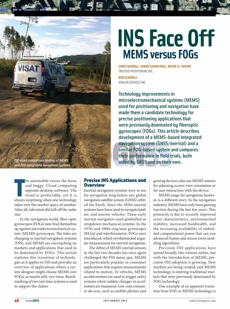
Off-road comparison testing of MEMS and FOG integrated navigation systems
www.insidegnss.com J U L Y / A U G U S T 2 0 1 2 InsideGNSS 49
in antenna array stabilization applica-tions. These applications were niched initially limited to for relatively static applications that needed precise atti-tude. Antenna array stabilization then began expanding into systems that were mounted within land vehicles. Usage was often for military communication systems, disaster monitoring systems, or expensive media communication systems.
Now MEMS are showing promis-ing performance for these applications enabling new uses for antenna array stabilization; such as two-way com-munication between UAVs and ground assets, streaming satellite TV to a car in downtown cities, or streaming video from a toy helicopter to a controller on the ground. Consumer advertising busi-nesses may even start to use directional antenna arrays to better target their cus-tomer base in new and innovative ways.
The future prospects of MEMS technology are intriguing, especially as a replacement for FOG technology in existing applications such as machine control, precision agriculture, vehicle navigationadvanced driver assistance systems, and unmanned ground/aerial/submersible vehicles (UGV/UAV/USV).
A Changing Cost/Benefit ScenarioAll machine control applications require, at their core, a system that tells the controller or actuator what to do; in other words a navigation system or positioning capability. A highly accu-rate navigation system based on inertial sensors traditionally depended on FOG or RLG technology. Organizations typi-cally spent $30,000+ for FOG naviga-tion systems because they were 20 times more accurate and reliable than the $500 MEMS navigation systems.
But what if a $500 MEMS system was only 20–30 percent less accurate than a $30,000 FOG navigation system? Would this change the buying decision?
The precision agriculture market is anxious for the accuracy of MEMS to improve. GNSS-only systems, includ-ing multi-antenna systems for attitude determination, created a market space
below the high-cost FOG systems. M u l t i - a n t e n n a systems are more expensive than sin-gle antenna systems due to the addition-al hardware, but even with this extra cost these multi-sensor systems are much less expensive than FOG-based INS/GNSS.
The next preci-sion agr icu lture products to enter the marketplace will fully integrate the lower-cost MEMS with the multi-anten-na GNSS to create a product that com-petes with the higher priced FOG INS/GNSS systems. These products are just now becoming available and will likely begin to gain market share.
Vehicle navigation systems have always been separated into the in-dash-built-in and mobile or portable naviga-tion device (PND) product offerings. Due to the price constraints on vehicles, FOGs never saw much penetration in automotive markets, except as bench-marking systems for MEMS navigation development.
In-dash systems always benefited from access to other vehicle sensors, including the odometer signal, which gave these systems a big advantage in terms of accuracy without GPS signals. The in-dash systems were also able to make use of existing MEMS inertial sensors within the vehicle, which kept costs low.
Similarly, PNDs adopted MEMS sen-sors to help bridge the gap between short GPS outages, such as through tunnels or in parking structures. Although PNDs were very price-constrained and could not compete with the accuracy of the in-dash systems, they had their share of the market. Vehicle navigation with MEMS is an active area of development in the space of automotive dead reckoning; therefore, higher grade FOG and RLG systems are still needed as benchmark or reference systems
The UGV/UAV/USV market is per-haps one of the most promising for pre-cision INS, especially using MEMS navi-gation. Military, aerospace, commercial, and even consumer applications exist for these platforms, which are often limited on power and payload, making MEMS an ideal candidate. Unfortunately, these platforms are also some of the hardest to navigate using low-cost INS because they are often designed for high dynam-ics and to operate for long periods of time without absolute navigation aids such as from GNSS.
The next section of this article will describe two versions of an INS/GNSS system that was built to use either FOG or MEMS gyroscopes. This navigation system used the same GNSS receiver, the same MEMS accelerometers, the same MEMS magnetometer, the same MEMS barometer, and the same soft-ware integration filter. The only differ-ence between the versions was the use of FOG or MEMS gyroscopes.
In Section 3, we will focus on the gyroscope technologies. Section 4 shows some comparative results of this system for land vehicle–based naviga-tion and quantifies the navigation per-formance differences between the FOG and MEMS variants. A brief outlook and conclusion is provided after the results.
A Real-Time INS/GNSS Navigation SystemThis particular navigation system was designed to provide attitude outputs at
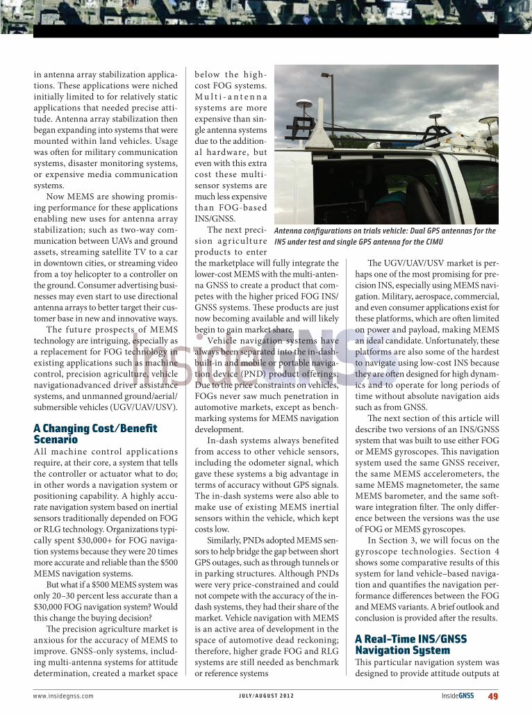
Antenna configurations on trials vehicle: Dual GPS antennas for the INS under test and single GPS antenna for the CIMU
50 InsideGNSS J U L Y / A U G U S T 2 0 1 2 www.insidegnss.com
high rates to a motor, which then sta-bilized an antenna array on the roof of a vehicle. The purpose of the antenna array was to maintain communication with a geostationary satellite.
The real-time navigation system was implemented as a strapdown INS/GNSS navigator, which also output high rate positions and velocities. One particular requirement of the system was to pro-vide attitude estimates at high output rates with a bandwidth over 300 hertz. We designed the actual system to out-put attitude estimates at 1,000 hertz in real-time.
Inertial measurement unit (IMU) data f lowed to the navigation filter at 1,024 hertz, and these data were used to predict the position, velocity, and atti-tude solution. GNSS positions, veloci-ties, and headings derived from dual antennas were used as updates to the navigation filter. A barometer was also
used within this navigation filter to aid altitude.
We incorporated a magnetometer into the sys-tem to initialize the head-ing and provide a weak heading update during long GNSS signal outages. Special calibration routines also occurred in parallel to the navigation filter. These routines calibrated the magnetometer, the dual-antenna mounting mis-alignment, and the level of vehicle vibrations for static period detection.
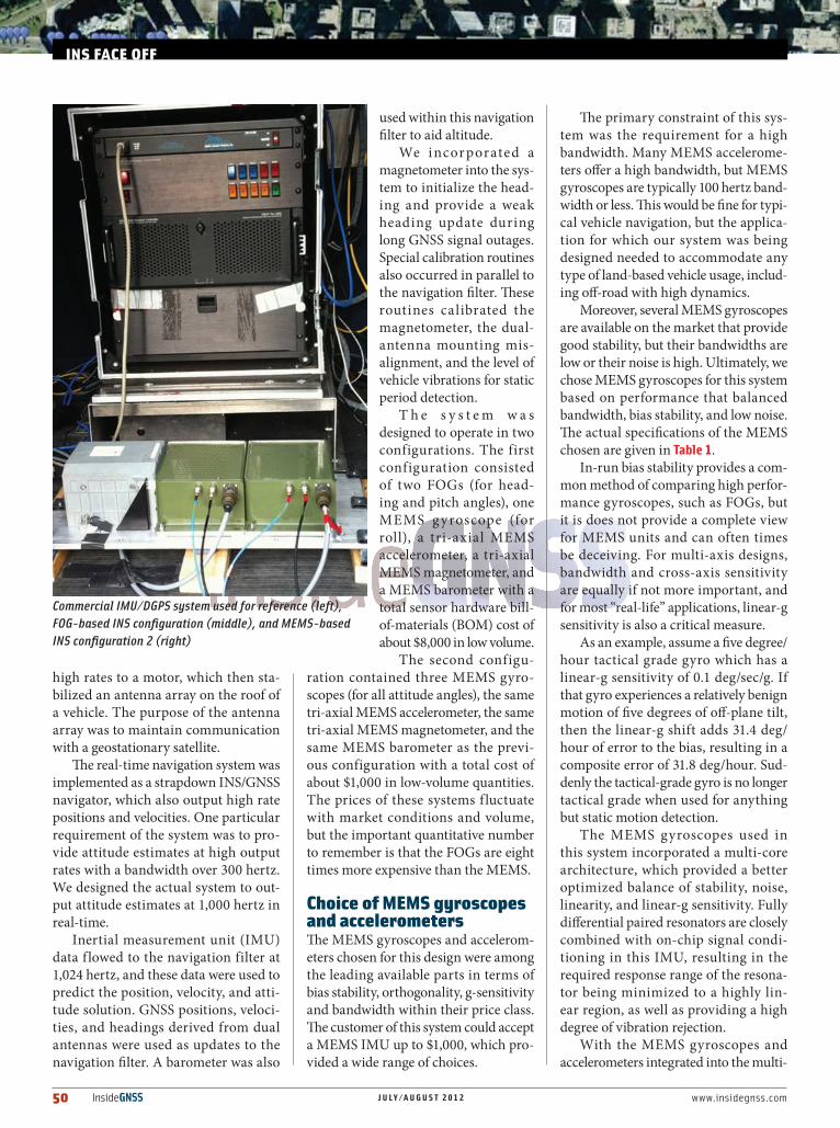
T h e s y s t e m w a s designed to operate in two configurations. The first configuration consisted of two FOGs (for head-ing and pitch angles), one MEMS g yroscope (for roll), a tri-axial MEMS accelerometer, a tri-axial MEMS magnetometer, and a MEMS barometer with a total sensor hardware bill-of-materials (BOM) cost of about $8,000 in low volume.
The second configu-ration contained three MEMS gyro-scopes (for all attitude angles), the same tri-axial MEMS accelerometer, the same tri-axial MEMS magnetometer, and the same MEMS barometer as the previ-ous configuration with a total cost of about $1,000 in low-volume quantities. The prices of these systems f luctuate with market conditions and volume, but the important quantitative number to remember is that the FOGs are eight times more expensive than the MEMS.
Choice of MEMS gyroscopes and accelerometersThe MEMS gyroscopes and accelerom-eters chosen for this design were among the leading available parts in terms of bias stability, orthogonality, g-sensitivity and bandwidth within their price class. The customer of this system could accept a MEMS IMU up to $1,000, which pro-vided a wide range of choices.
The primary constraint of this sys-tem was the requirement for a high bandwidth. Many MEMS accelerome-ters offer a high bandwidth, but MEMS gyroscopes are typically 100 hertz band-width or less. This would be fine for typi-cal vehicle navigation, but the applica-tion for which our system was being designed needed to accommodate any type of land-based vehicle usage, includ-ing off-road with high dynamics.
Moreover, several MEMS gyroscopes are available on the market that provide good stability, but their bandwidths are low or their noise is high. Ultimately, we chose MEMS gyroscopes for this system based on performance that balanced bandwidth, bias stability, and low noise. The actual specifications of the MEMS chosen are given in Table 1.
In-run bias stability provides a com-mon method of comparing high perfor-mance gyroscopes, such as FOGs, but it is does not provide a complete view for MEMS units and can often times be deceiving. For multi-axis designs, bandwidth and cross-axis sensitivity are equally if not more important, and for most “real-life” applications, linear-g sensitivity is also a critical measure.
As an example, assume a five degree/hour tactical grade gyro which has a linear-g sensitivity of 0.1 deg/sec/g. If that gyro experiences a relatively benign motion of five degrees of off-plane tilt, then the linear-g shift adds 31.4 deg/hour of error to the bias, resulting in a composite error of 31.8 deg/hour. Sud-denly the tactical-grade gyro is no longer tactical grade when used for anything but static motion detection.
The MEMS gyroscopes used in this system incorporated a multi-core architecture, which provided a better optimized balance of stability, noise, linearity, and linear-g sensitivity. Fully differential paired resonators are closely combined with on-chip signal condi-tioning in this IMU, resulting in the required response range of the resona-tor being minimized to a highly lin-ear region, as well as providing a high degree of vibration rejection.
With the MEMS gyroscopes and accelerometers integrated into the multi-
INS FACE OFF
Commercial IMU/DGPS system used for reference (left), FOG-based INS configuration (middle), and MEMS-based INS configuration 2 (right)
www.insidegnss.com J U L Y / A U G U S T 2 0 1 2 InsideGNSS 51
axis IMU, a potentially dominant error source is also the x/y/z nonorthogonality of the sensors. This metric is commonly specified as either cross-axis sensitivity or misalignment. A fairly typical speci-fication is ±2 percent cross-axis sensitiv-ity for MEMS. The IMU of this system, however, has a cross-axis sensitivity of 0.087 percent (0.05 degree orthogonal-ity). More importantly, this specification holds over temperature variations, as a result of a device specific calibration per-formed at the factory.
For a given rotation rate, on for instance the yaw axis, the orthogonal axis will have a rate output equal to CrossAxisSensitivity * YawRate, even when real rotation on the roll and pitch axis is zero. A two percent cross-axis error will typically result in an order-of-magnitude greater off-axis noise adder beyond the native gyro noise; whereas the 0.087 percent sensitivity of the IMU used in this system is carefully balanced to the native gyro noise level.
Also critical to multi-axis designs is the available bandwidth and its asso-ciated relevance to the ability to phase match across the axis. Some gyro struc-tures have restricted bandwidths asso-ciated with total noise reduction, while others have limited bandwidth, typi-cally below 100 hertz, as a result of the sensor processing used in the feedback electronics. These limitations can result in added phase-related errors rippling through the sensor signal path, par-ticularly in the Kalman filter. With 330 hertz of available bandwidth, the chosen MEMS IMU provided a well-balanced approach to minimize the total error sources.
Choice of FOGsWe chose the FOGs based on a com-bination of price, bandwidth, and size. The bias stability and noise level of the FOGs were also a determining factor in the final choice of sensors. The impor-tant performance parameters are given in Table 2. The FOGs have better bias stability and a significant improvement of angular random walk in comparison to the MEMS.
Overview of System-Level TestsDatasheets are often deceiving; so, to properly compare both systems, three system-level navigation benchmarking tests were devised: 1) Open sky with good GNSS signals to
assess the accuracy of roll, pitch, and heading.
2) GNSS multipath and GNSS signal outage scenarios, such as in urban downtown areas where the GNSS solution could be of poor quality or unavailable due to tall buildings. The intent of this test was to compare the filtered position and attitude perfor-mance.
3) INS-only performance to evalu-ate the navigation performance if the system is to be used without ever having access to GNSS signals. In this scenario the system can be started from a user defined position. This use-case may be applicable for military applications where GNSS cannot be trusted, or if the vehicle cannot accept any wireless signals from its starting location, such as within a garage. This use-case was also chosen to more clearly see the differ-ences between the two naviga-tion systems.The benchmark-
ing of both systems was performed in comparison to a navigation grade IMU that was inte-grated with a differ-ential GPS solution. This reference real-time solution was then post-processed u s i ng a R auch-Tung-Striebel (RTS) smoother algorithm to get a forward-backward solution. This reference sys-tem was considered accurate to better
than 0.03 degrees all the time with cen-timeter-level positioning accuracy.
Open-Sky ResultsWhen the GPS was available with a clear line of sight to several satellites, the posi-tioning results were comparable between both systems. The velocity results were also largely determined by the GPS receivers and the accelerometers; so, no large differences were seen in velocity performance in open sky. The primary navigation parameters that we com-pared were the attitude angles — roll, pitch, and heading — because these are largely determined by the gyroscope performance.
We performed paved and off-road driving tests in order to compare the attitude solutions of the two systems. The paved results are presented in Table 3.
The FOG system is slightly better than the MEMS, but only by less than 5 percent when on pavement. An off-road test was also performed to evaluate if the FOG had advantages in higher dynamic situations. This off-road test involved
Measure of Performance Value Units
Gyroscopes Bandwidth 330 Hz
Bias Instability 6 (z) & 20 (x/y) deg/hr
Angular Random Walk 0.75 (z) & 1.9 (x/y) deg/sqrt(hr)
Accelerometers Bandwidth 330 Hz
Bias Instability 50 µg
Velocity Random Walk 0.09 m/s/sqrt(hr)
TABLE 1. MEMS IMU specifications
Measure of Performance Value Units
Gyroscopes Bandwidth 1,000 Hz
Bias Stability 3 deg/hr
Angular Random Walk 0.1 deg/sqrt(hr)
TABLE 2. FOG specifications
System Roll RMSPitch RMS
Heading RMS
% time Roll < 0.3 deg
% time Pitch
< 0.3 deg
% time Head
< 0.3 deg
FOG 0.15 0.08 0.15 95.60 97.95 98.38
MEMS 0.08 0.09 0.16 98.04 95.70 87.90
TABLE 3. Paved road attitude results
52 InsideGNSS J U L Y / A U G U S T 2 0 1 2 www.insidegnss.com
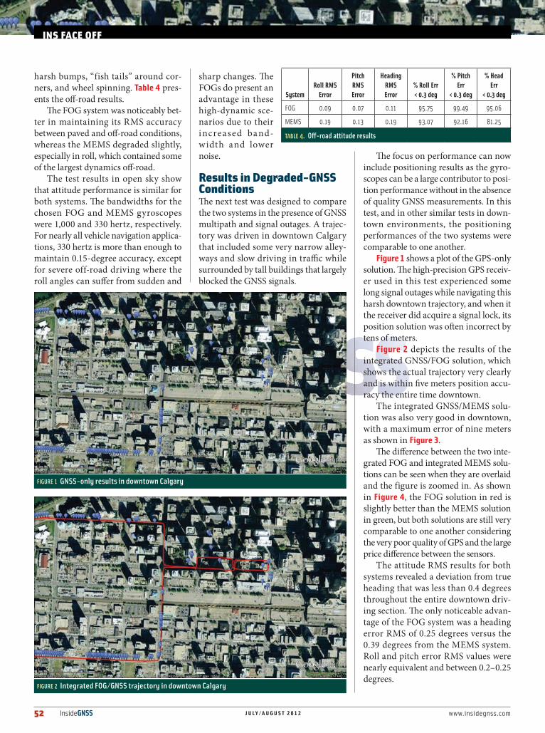
harsh bumps, “fish tails” around cor-ners, and wheel spinning. Table 4 pres-ents the off-road results.
The FOG system was noticeably bet-ter in maintaining its RMS accuracy between paved and off-road conditions, whereas the MEMS degraded slightly, especially in roll, which contained some of the largest dynamics off-road.
The test results in open sky show that attitude performance is similar for both systems. The bandwidths for the chosen FOG and MEMS gyroscopes were 1,000 and 330 hertz, respectively. For nearly all vehicle navigation applica-tions, 330 hertz is more than enough to maintain 0.15-degree accuracy, except for severe off-road driving where the roll angles can suffer from sudden and
sharp changes. The FOGs do present an advantage in these high-dynamic sce-narios due to their increased ba nd-width and lower noise.
Results in Degraded-GNSS ConditionsThe next test was designed to compare the two systems in the presence of GNSS multipath and signal outages. A trajec-tory was driven in downtown Calgary that included some very narrow alley-ways and slow driving in traffic while surrounded by tall buildings that largely blocked the GNSS signals.
The focus on performance can now include positioning results as the gyro-scopes can be a large contributor to posi-tion performance without in the absence of quality GNSS measurements. In this test, and in other similar tests in down-town environments, the positioning performances of the two systems were comparable to one another.
Figure 1 shows a plot of the GPS-only solution. The high-precision GPS receiv-er used in this test experienced some long signal outages while navigating this harsh downtown trajectory, and when it the receiver did acquire a signal lock, its position solution was often incorrect by tens of meters.
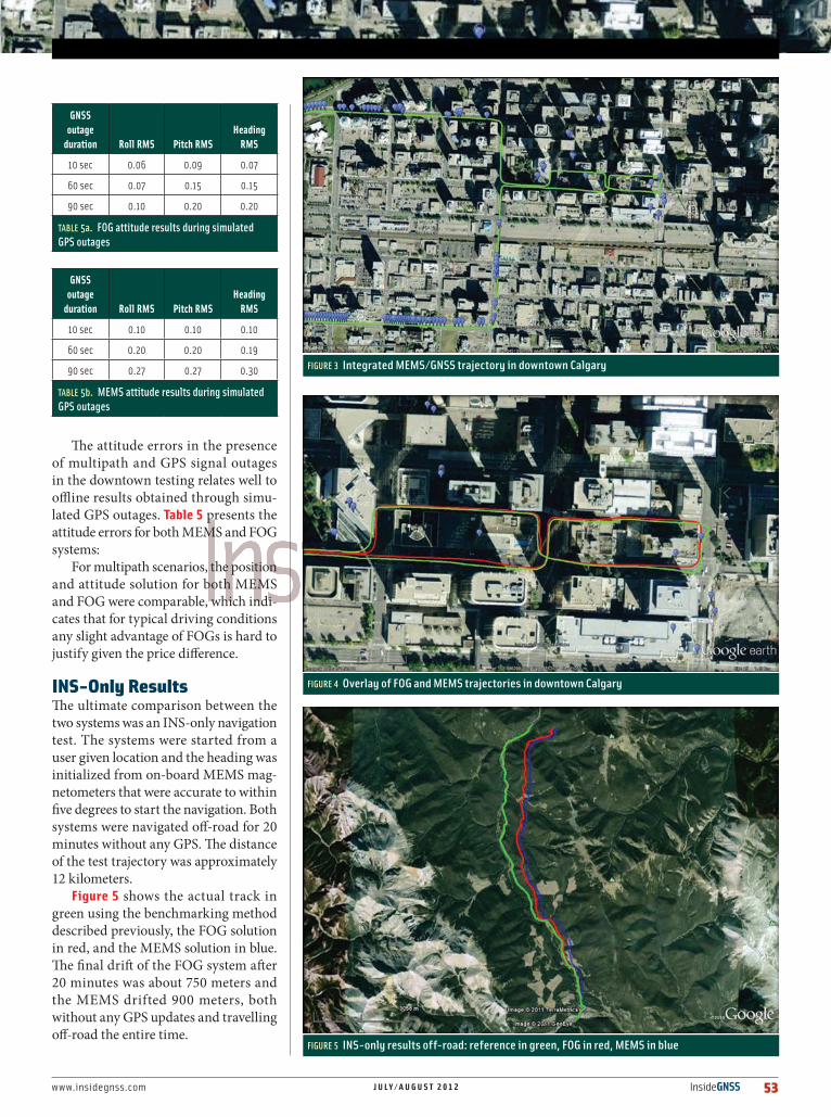
Figure 2 depicts the results of the integrated GNSS/FOG solution, which shows the actual trajectory very clearly and is within five meters position accu-racy the entire time downtown.
The integrated GNSS/MEMS solu-tion was also very good in downtown, with a maximum error of nine meters as shown in Figure 3.
The difference between the two inte-grated FOG and integrated MEMS solu-tions can be seen when they are overlaid and the figure is zoomed in. As shown in Figure 4, the FOG solution in red is slightly better than the MEMS solution in green, but both solutions are still very comparable to one another considering the very poor quality of GPS and the large price difference between the sensors.
The attitude RMS results for both systems revealed a deviation from true heading that was less than 0.4 degrees throughout the entire downtown driv-ing section. The only noticeable advan-tage of the FOG system was a heading error RMS of 0.25 degrees versus the 0.39 degrees from the MEMS system. Roll and pitch error RMS values were nearly equivalent and between 0.2–0.25 degrees.
INS FACE OFF
FIGURE 1 GNSS-only results in downtown Calgary
FIGURE 2 Integrated FOG/GNSS trajectory in downtown Calgary
SystemRoll RMS
Error
Pitch RMS Error
Heading RMS Error
% Roll Err < 0.3 deg
% Pitch Err
< 0.3 deg
% Head Err
< 0.3 deg
FOG 0.09 0.07 0.11 95.75 99.49 95.06
MEMS 0.19 0.13 0.19 93.07 92.16 81.25
TABLE 4. Off-road attitude results
www.insidegnss.com J U L Y / A U G U S T 2 0 1 2 InsideGNSS 53
The attitude errors in the presence of multipath and GPS signal outages in the downtown testing relates well to offline results obtained through simu-lated GPS outages. Table 5 presents the attitude errors for both MEMS and FOG systems:
For multipath scenarios, the position and attitude solution for both MEMS and FOG were comparable, which indi-cates that for typical driving conditions any slight advantage of FOGs is hard to justify given the price difference.
INS-Only ResultsThe ultimate comparison between the two systems was an INS-only navigation test. The systems were started from a user given location and the heading was initialized from on-board MEMS mag-netometers that were accurate to within five degrees to start the navigation. Both systems were navigated off-road for 20 minutes without any GPS. The distance of the test trajectory was approximately 12 kilometers.
Figure 5 shows the actual track in green using the benchmarking method described previously, the FOG solution in red, and the MEMS solution in blue. The final drift of the FOG system after 20 minutes was about 750 meters and the MEMS drifted 900 meters, both without any GPS updates and travelling off-road the entire time.
FIGURE 3 Integrated MEMS/GNSS trajectory in downtown Calgary
FIGURE 4 Overlay of FOG and MEMS trajectories in downtown Calgary
FIGURE 5 INS-only results off-road: reference in green, FOG in red, MEMS in blue
GNSS outage
duration Roll RMS Pitch RMSHeading
RMS
10 sec 0.06 0.09 0.07
60 sec 0.07 0.15 0.15
90 sec 0.10 0.20 0.20
TABLE 5a. FOG attitude results during simulated GPS outages
GNSS outage
duration Roll RMS Pitch RMSHeading
RMS
10 sec 0.10 0.10 0.10
60 sec 0.20 0.20 0.19
90 sec 0.27 0.27 0.30
TABLE 5b. MEMS attitude results during simulated GPS outages
54 InsideGNSS J U L Y / A U G U S T 2 0 1 2 www.insidegnss.com
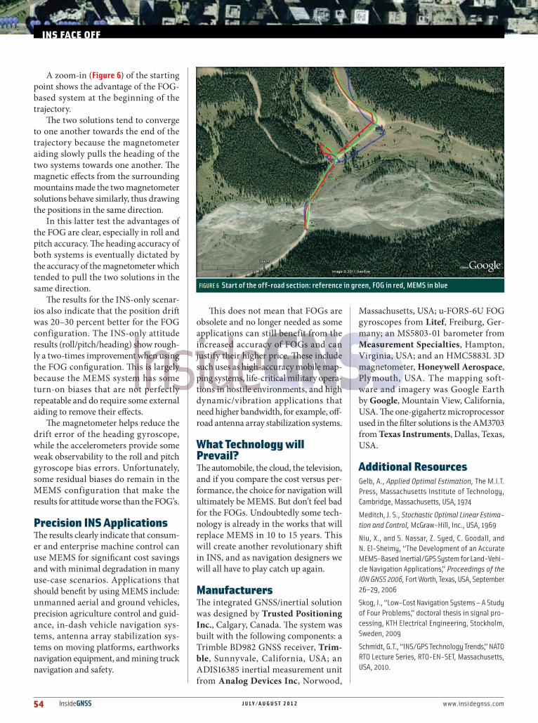
A zoom-in (Figure 6) of the starting point shows the advantage of the FOG-based system at the beginning of the trajectory.
The two solutions tend to converge to one another towards the end of the trajectory because the magnetometer aiding slowly pulls the heading of the two systems towards one another. The magnetic effects from the surrounding mountains made the two magnetometer solutions behave similarly, thus drawing the positions in the same direction.
In this latter test the advantages of the FOG are clear, especially in roll and pitch accuracy. The heading accuracy of both systems is eventually dictated by the accuracy of the magnetometer which tended to pull the two solutions in the same direction.
The results for the INS-only scenar-ios also indicate that the position drift was 20–30 percent better for the FOG configuration. The INS-only attitude results (roll/pitch/heading) show rough-ly a two-times improvement when using the FOG configuration. This is largely because the MEMS system has some turn-on biases that are not perfectly repeatable and do require some external aiding to remove their effects.
The magnetometer helps reduce the drift error of the heading gyroscope, while the accelerometers provide some weak observability to the roll and pitch gyroscope bias errors. Unfortunately, some residual biases do remain in the MEMS configuration that make the results for attitude worse than the FOG’s.
Precision INS ApplicationsThe results clearly indicate that consum-er and enterprise machine control can use MEMS for significant cost savings and with minimal degradation in many use-case scenarios. Applications that should benefit by using MEMS include: unmanned aerial and ground vehicles, precision agriculture control and guid-ance, in-dash vehicle navigation sys-tems, antenna array stabilization sys-tems on moving platforms, earthworks navigation equipment, and mining truck navigation and safety.
This does not mean that FOGs are obsolete and no longer needed as some applications can still benefit from the increased accuracy of FOGs and can justify their higher price. These include such uses as high-accuracy mobile map-ping systems, life-critical military opera-tions in hostile environments, and high dynamic/vibration applications that need higher bandwidth, for example, off-road antenna array stabilization systems.
What Technology will Prevail?The automobile, the cloud, the television, and if you compare the cost versus per-formance, the choice for navigation will ultimately be MEMS. But don’t feel bad for the FOGs. Undoubtedly some tech-nology is already in the works that will replace MEMS in 10 to 15 years. This will create another revolutionary shift in INS, and as navigation designers we will all have to play catch up again.
ManufacturersThe integrated GNSS/inertial solution was designed by Trusted Positioning Inc., Calgary, Canada. The system was built with the following components: a Trimble BD982 GNSS receiver, Trim-ble, Sunnyvale, California, USA; an ADIS16385 inertial measurement unit from Analog Devices Inc, Norwood,
Massachusetts, USA; u-FORS-6U FOG gyroscopes from Litef, Freiburg, Ger-many; an MS5803-01 barometer from Measurement Specialties, Hampton, Virginia, USA; and an HMC5883L 3D magnetometer, Honeywell Aerospace, Plymouth, USA. The mapping soft-ware and imagery was Google Earth by Google, Mountain View, California, USA. The one-gigahertz microprocessor used in the filter solutions is the AM3703 from Texas Instruments, Dallas, Texas, USA.
Additional ResourcesGelb, A., Applied Optimal Estimation, The M.I.T. Press, Massachusetts Institute of Technology, Cambridge, Massachusetts, USA, 1974
Meditch, J. S., Stochastic Optimal Linear Estima-tion and Control, McGraw-Hill, Inc., USA, 1969
Niu, X., and S. Nassar, Z. Syed, C. Goodall, and N. El-Sheimy, “The Development of an Accurate MEMS-Based Inertial/GPS System for Land-Vehi-cle Navigation Applications,” Proceedings of the ION GNSS 2006, Fort Worth, Texas, USA, September 26–29, 2006
Skog, I., “Low-Cost Navigation Systems – A Study of Four Problems,” doctoral thesis in signal pro-cessing, KTH Electrical Engineering, Stockholm, Sweden, 2009
Schmidt, G.T., “INS/GPS Technology Trends,” NATO RTO Lecture Series, RTO-EN-SET, Massachusetts, USA, 2010.
INS FACE OFF
FIGURE 6 Start of the off-road section: reference in green, FOG in red, MEMS in blue

www.insidegnss.com J U L Y / A U G U S T 2 0 1 2 InsideGNSS 55
AuthorsChris Goodall is a co-founder and the vice-president of applications at Trusted Positioning Inc., Calgary, Alberta, Canada. Goodall has been working in devel-
oping, deploying, and testing multi-sensor navi-gation systems for more than eight years. He obtained his B.Sc. in systems design engineering at the University of Waterloo, Canada and his Ph.D. in geomatics engineering from the University of Calgary.
Sarah Carmichael is the marketing coordinator at Trusted Positioning Inc., where she is responsible for all forms of market-ing and communications material. Carmichael
received her B.Comm. in marketing from the Has-kayne School of Business at the University of Calgary.
Naser El-Sheimy is a co-founder and the CEO of Trusted Positioning Inc. and the leader of the Mobile Multi-sensor Research Group at the University of Calgary,
Alberta, Canada. He holds a Canada Research Chair (CRC) in Mobile Multi-Sensor Geomatics Systems, and his area of expertise is in the integration of GNSS/INS/imaging sensors for navigation, map-ping, and geographic information system applica-tions with an emphasis on the use of multi-sen-sors in portable navigation systems. He achieved a B.Sc. degree in civil engineering and an M.Sc. degree in surveying engineering from Ain Shams University, Egypt, and a Ph.D. in geomatics engi-neering from the University of Calgary.
Bob Scannell is a business development manager for ADI’s inertial MEMs products. He has been with ADI for more than 15 years in various techni-cal marketing and busi-
ness development functions, ranging from sen-sors to DSP digital signal processing to wireless, and previously worked at Rockwell International in both design and marketing. He holds a B.S. degree in electrical engineering from the Univer-sity of California, Los Angeles, and an M.S. in computer engineering from the University of Southern California.


![Proton Magnetometer [LG.Huggard].pdf](https://img.pdfslide.us/doc/110x75/55cf96e3550346d0338e7412/proton-magnetometer-lghuggardpdf.jpg)
