Embed Size (px)
Citation preview
InRouter 6x5 Series User’s Manual
© 2014 InHand Networks, All rights reserved.
Republication without permission is prohibited.
InRouter 6x5 Series User’s Manual
Copyright Notice
Copyright © 2014 InHand Networks
All rights reserved.
Reproduction without permission is prohibited.
Trademarks
InHand is a registered trademark of InHand Networks. Other registered marks cited in this manual represented their
respective companies.
Disclaimer
Information in this document is subject to change without notice and does not represent an obligation on the part of InHand
Networks.
This user manual may include intentional technical or typographical errors. Changes are periodically made to the manual to
correct such errors, and these changes are not informed in new editions.
Technical Support Contact Information
InHand Networks, China
Tel: +86-010-64391099
Fax: +86-010-64399872
Email: [email protected]
Content
Introduction to InRouter 6x5 Series ........................................................................................................................................... 1
1.1 Overview ...................................................................................................................................................................... 2
1.2 Package Checklist ......................................................................................................................................................... 4
1.3 Product Features ........................................................................................................................................................... 5
1.3.1 Interfaces ........................................................................................................................................................... 5
1.3.2 Functions ........................................................................................................................................................... 6
1.3.3 Environmental Limits ........................................................................................................................................ 7
1.3.4 Power Requirements .......................................................................................................................................... 7
1.3.5 Physical Characteristics ..................................................................................................................................... 7
1.3.6 Advanced Industrial Characteristics .................................................................................................................. 8
1.3.7 Device Management Software ........................................................................................................................... 8
1.3.8 Warranty ............................................................................................................................................................ 8
Quick Installation Guide ........................................................................................................................................................... 10
2.1 Typical Application ..................................................................................................................................................... 10
2.2 Panel Layout ............................................................................................................................................................... 12
Description of LED .................................................................................................................................................. 12
Signal Status LED Description ................................................................................................................................. 13
2.3 Quick Connection to Internet ..................................................................................................................................... 14
2.3.1 Insert SIM Card ............................................................................................................................................... 14
2.3.2 Antenna Installation ......................................................................................................................................... 14
2.3.3 Power Supply ................................................................................................................................................... 14
2.3.4 Connect ............................................................................................................................................................ 14
2.3.5 Build Connection between InRouter and PC ................................................................................................... 14
2.3.6 Start to configure your InRouter 6x5(Optional) .............................................................................................. 16
2.3.7 Connect InRouter with Internet ....................................................................................................................... 17
2.4 Quick IPSec VPN Configuration ................................................................................................................................ 19
2.5 Reset to Factory Defaults ........................................................................................................................................... 21
2.5.1 Hardware Approach ......................................................................................................................................... 21
2.5.2 Web Approach ................................................................................................................................................. 22
Advanced Configuration .......................................................................................................................................................... 23
3.1 Configuration on Web ................................................................................................................................................. 23
3.1.1 Preparation ....................................................................................................................................................... 23
3.1.2 System ............................................................................................................................................................. 24
3.1.3 Network ........................................................................................................................................................... 28
3.1.4 Service ............................................................................................................................................................. 37
3.1.5 Firewall ............................................................................................................................................................ 41
3.1.6 QoS .................................................................................................................................................................. 43
3.1.7 VPN ................................................................................................................................................................. 44
3.1.8 Tools ................................................................................................................................................................ 51
3.1.9 Status ............................................................................................................................................................... 52
3.2 CLI Configuration ...................................................................................................................................................... 55
3.2.1 CLI Operation .................................................................................................................................................. 55
3.2.2 CLI command .................................................................................................................................................. 57
FAQ .......................................................................................................................................................................................... 59

Support ..................................................................................................................................................................................... 61

I
Introduction to InRouter 6x5 Series
◆Overview
◆Package Checklist
◆Product Features & Specifications
◆Product Models
2 / 65
1.1 Overview
InRouter6x5 series products are M2M wireless routers that integrate 3G network and virtual private network (VPN)
technologies. The products meet fundamental needs of field communication in industry, support international commercial
UMTS (HSPA+), CDMA2000 1x EV-DO (Rev. A), TD-SCDMA networks, and respectively backward compatible with
EDGE, CDMA 1X and GPRS network.
The design of the InRouter6x5 series fully incorporated the requirements of industrial users, adopted multi-level
software detection mechanism, and supporting InHand Device Manager Cloud, which facilitates remote management,
ensuring stable operation of devices, achieving intelligent management. Multiple VPN protocol ensures security in data
transmission, preventing malicious access and tampering of data. The humanized WEB configuration interface is easy for
customer to use. It supports Wi-Fi (optional), providing wireless LAN access and wireless user identification authentication
services on customer site. It also supports connection to multiple network devices, enabling multi service processing.
The IR6x5 series wireless routers are the ideal choice for industrial usage, having low power consumption, wide
working temperature range from -20°C to 70°C, small size and light weight that is easy for application in harsh, narrow
industrial environment. The series includes multiple models like InRouter605, and InRouter695, and multiple types of
wireless networks to meet various function needs of customers.
3 / 65
Important Safety Information
This product is not intended for use in the following circumstances
Area(s) where radio transmission equipment (such as cell phone) are not permitted.
Hospitals, health care facilities and area(s) where cell phones are restricted by law.
Gas stations, fuel storage and places where chemical are stored.
Chemical plants or places with potential explosion hazard.
Any metal surface that may weaken the radio signal level.
RF safety distance
For GPRS router, the compliance boundary distance is r=0.26m for GSM 900MHz and r=0.13m for DCS 1800 MHz.
For HSUPA router, the compliance boundary distance is r=0.26m for GSM 900MHz and
r=0.13m for DCS 1800 MHz, r=.0.094 for WCDMA 900MHz, r=0.063 for WCDMA 2100MHz.
Warning
This is a class A product. In a domestic environment this product may cause radio interference in which case the
user may be required to take adequate measures.
WEEE Notice
The Directive on Waste Electrical and Electronic Equipment (WEEE), which entered into force as European law on
13th February 2003, resulted in a major change in the treatment of electrical equipment at end-of-life.
The purpose of this Directive is, as a first priority, the prevention of WEEE, and in addition, to promote the reuse,
recycling and other forms of recovery of such wastes so as to reduce disposal.
The WEEE logo (shown at the left) on the product or on its box indicates that this product must not be disposed of
or dumped with your other household waste. You are liable to dispose of all your electronic or electrical waste
equipment by relocating over to the specified collection point for recycling of such hazardous waste. Isolated
collection and proper recovery of your electronic and electrical waste equipment at the time of disposal will allow
us to help conserving natural resources. Moreover, proper recycling of the electronic and electrical waste
equipment will ensure safety of human health and environment.
For more information about electronic and electrical waste equipment disposal, recovery, and collection points,
please contact your local city centre, household waste disposal service, shop from where you purchased the
equipment, or manufacturer of the equipment.
4 / 65
1.2 Package Checklist
We put each InRouter 6x5 cellular router in a box with standard accessories. Additionally, there’re optional accessories
can be ordered. When you receive our package, please check carefully, and if there’re items missing or appearing to be
damaged, please contact with your InHand Networks sales representative.
Items in package include:
Standard Accessories:
Accessories Description
InRouter6x5 Serials Wireless Router 1
Cable 1 Cross line,CAT-5,1.5M
Document and Software CD 1
Antenna 3m Cellular Antenna
Power Supply
Power Adapter, 100-265V AC in, 12V DC out
(included in IR6x5)
Optional Antennas:
Picture Type Description
GSM/GPRS Cellular Antennas
GPRS Quad-band
(included in IR6x5GS55)
UMTS/HSPA+ Cellular Antennas
UTMS Quad-band
(included in IR6x5PH09)
Anti-thief antenna
UTMS Quad-band
(Optional for IR6x5PH09)
Stick antenna
UTMS Quad-band
(Optional for IR6x5PH09)
Anti-thief antenna
UTMS Quad-band
(Optional for IR6x5PH09)
5 / 65
1.3 Product Features
1.3.1 Interfaces
WAN
Cellular WAN:
Band Options:
GSM/GPRS/EDGE:
850/900/1800/1900 MHz
UMTS /HSPA/HSPA+:
850/900/1900/2100 MHz
Ethernet WAN:
Ethernet: 10/100 Mbps, RJ45 connector, Auto MDI/MDIX
Magnetic Isolation Protection: 1.5 KV built-in
Wi-Fi (Optional)
Wireless: 150Mbps 802.11b/g/n Work mode: AP/Client
LAN
Number of Ports: 3
Ethernet: 10/100 Mbps, RJ45 connector, Auto MDI/MDIX
Magnetic Isolation Protection: 1.5 KV built-in
DMZ
Number of Ports: 1
Ethernet: 10/100 Mbps, RJ45 connector, Auto MDI/MDIX
Magnetic Isolation Protection: 1.5 KV built-in
Serial
A. Serial Type: RS232/485
B. Data bit: 5/6/7/8
C. Stop bit: 1/2
D. Check bit: N/O/D
E. Baud rate: 3,200bit/s~ 115,200bit/s
SIM Interface
SIM Control: 3 V
6 / 65
1.3.2 Functions
PPP
Support VPDN/APN, fast access to virtual private dial-up network (VPDN) provided by mobile operator, ensure
high-security data transmission.
Support CHAP/PAP/MS-CHAP/MS-CHAP V2 authorization
Support Connection Detection, auto-recovery, auto-link, ensure reliable communication.
Support On-demand connection, SMS Activity
Wi-Fi (Optional)
Wireless: 150Mbps 802.11b/g/n Work mode: AP/Client
Authentication: open, WEP, WPA/WPA-2(Personal), PA/WPA-2(Enterprise)
Dynamic IP
Support DHCP, applied as Server/Client
Dynamic DNS
Support Dynamic DNS-IP Binding
Provide DDNS analyze to help access dynamic data center
Flux Management
Support rate limiting,
Firewall Function
Package filtering
Port Mapping
Virtual Address Mapping
DMZ zone
MAC addresses binding.
Route function
Support Static Routing Table
VPN (for IR691 only)
IPSec/SSL VPN
L2TP/PPTP VPN
GRE
Link Backup
VRRP
Support VRRP protocols, realizing immediate link backup
DNS Forwarding
Support DNS Forwarding, support DNS record
Network tools
Support Ping, Trace Route and Telnet
7 / 65
1.3.3 Environmental Limits
Operating Temperature: -20 to 70°C (-4 to 158°F)
Operating Humidity: 5 to 95% RH
Storage Temperature: -40 to 85°C (-40 to 167°F)
1.3.4 Power Requirements
Power Inputs: 1 terminal block, including power jack and serial.
Input Voltage: 9~26 VDC
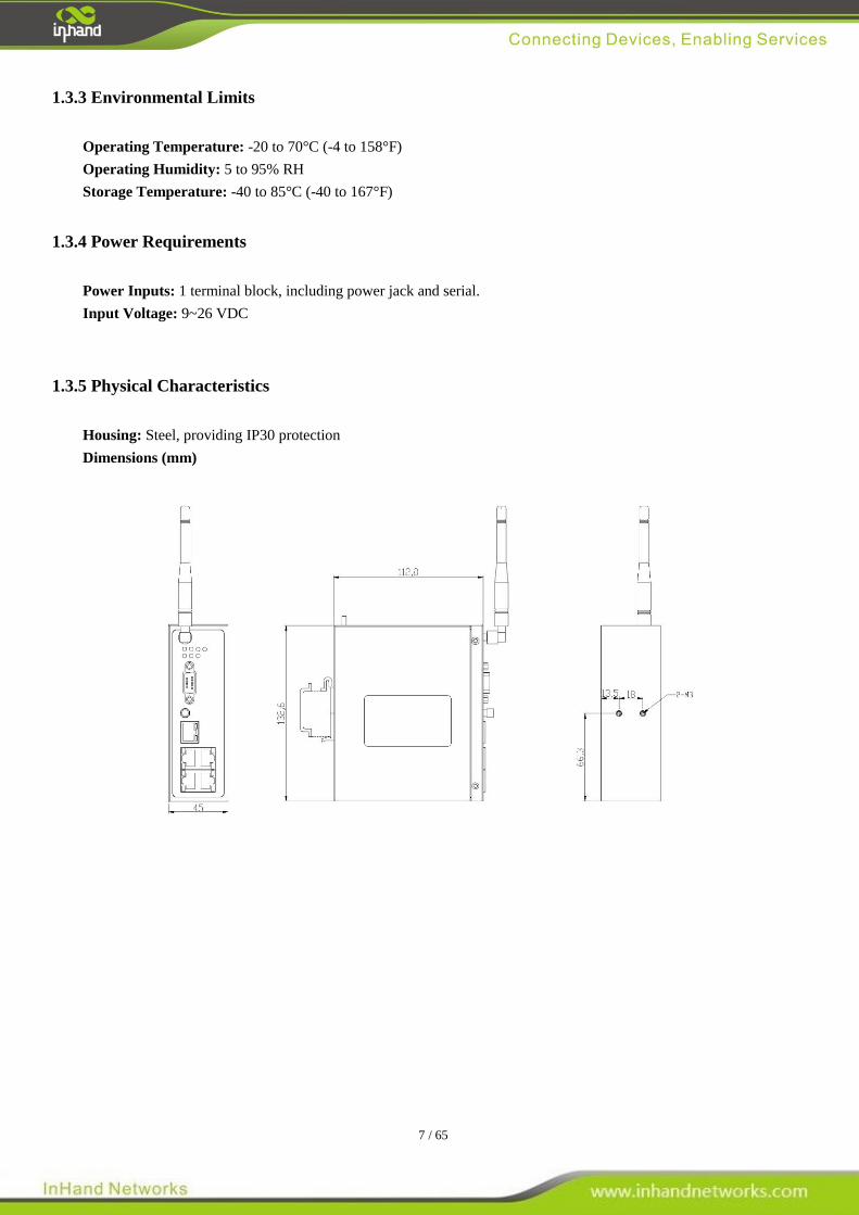
1.3.5 Physical Characteristics
Housing: Steel, providing IP30 protection
Dimensions (mm)

8 / 65
1.3.6 Advanced Industrial Characteristics
Physical Characteristics:
Shell: Metal, IP30
1.3.7 Device Management Software
Device Manager:
Centralized management solution for InHand Networks Devices
1.3.8 Warranty
Warranty Period: 1 year (Optional service for 3 years)
9 / 65
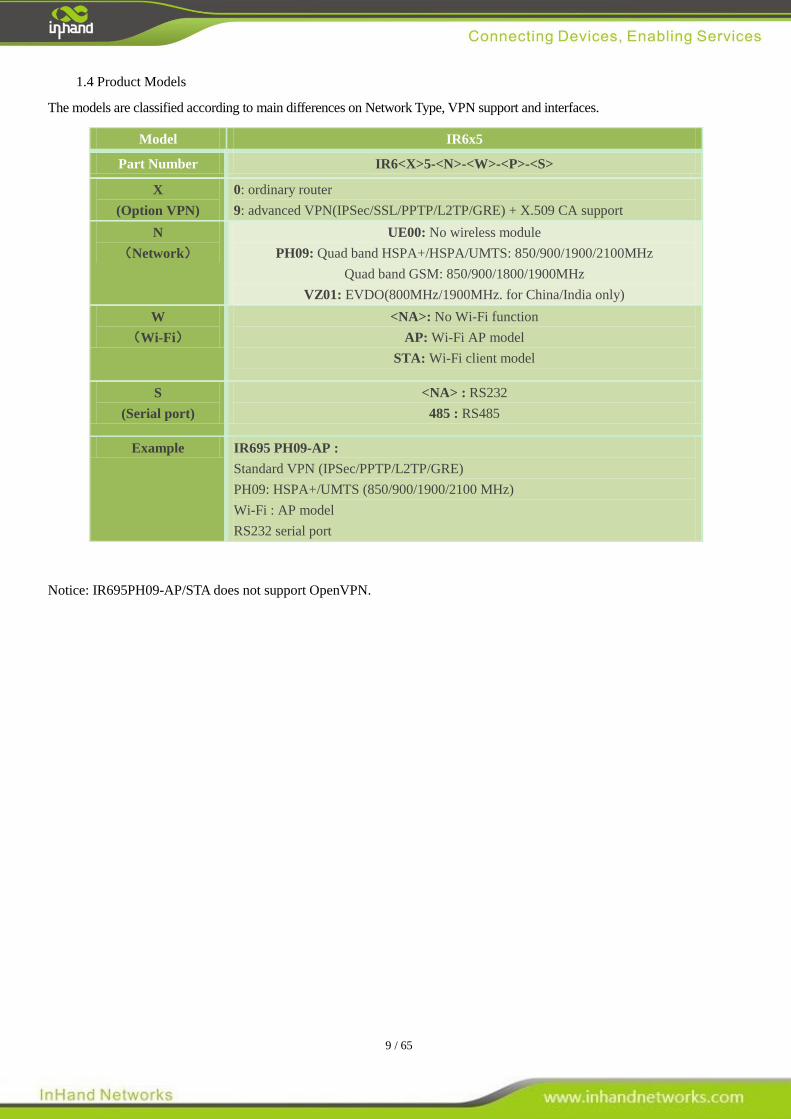
1.4 Product Models
The models are classified according to main differences on Network Type, VPN support and interfaces.
Notice: IR695PH09-AP/STA does not support OpenVPN.
Model IR6x5
Part Number IR6<X>5-<N>-<W>-<P>-<S>
X
(Option VPN)
0: ordinary router
9: advanced VPN(IPSec/SSL/PPTP/L2TP/GRE) + X.509 CA support
N
(Network)
UE00: No wireless module
PH09: Quad band HSPA+/HSPA/UMTS: 850/900/1900/2100MHz
Quad band GSM: 850/900/1800/1900MHz
VZ01: EVDO(800MHz/1900MHz. for China/India only)
W
(Wi-Fi)
<NA>: No Wi-Fi function
AP: Wi-Fi AP model
STA: Wi-Fi client model
S
(Serial port)
<NA> : RS232
485 : RS485
Example IR695 PH09-AP :
Standard VPN (IPSec/PPTP/L2TP/GRE)
PH09: HSPA+/UMTS (850/900/1900/2100 MHz)
Wi-Fi : AP model
RS232 serial port
10 / 65
II
Quick Installation Guide
◆ Typical Application
◆ Panel Layout
◆ Quick Connect to Internet
◆ Quick IPSec VPN Configuration
◆ Reset to Factory Defaults
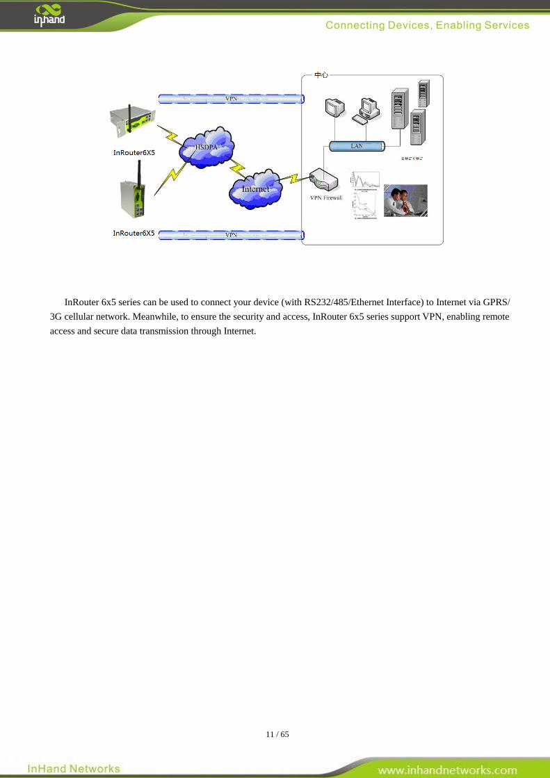
2.1 Typical Application
11 / 65
InRouter 6x5 series can be used to connect your device (with RS232/485/Ethernet Interface) to Internet via GPRS/
3G cellular network. Meanwhile, to ensure the security and access, InRouter 6x5 series support VPN, enabling remote
access and secure data transmission through Internet.
12 / 65
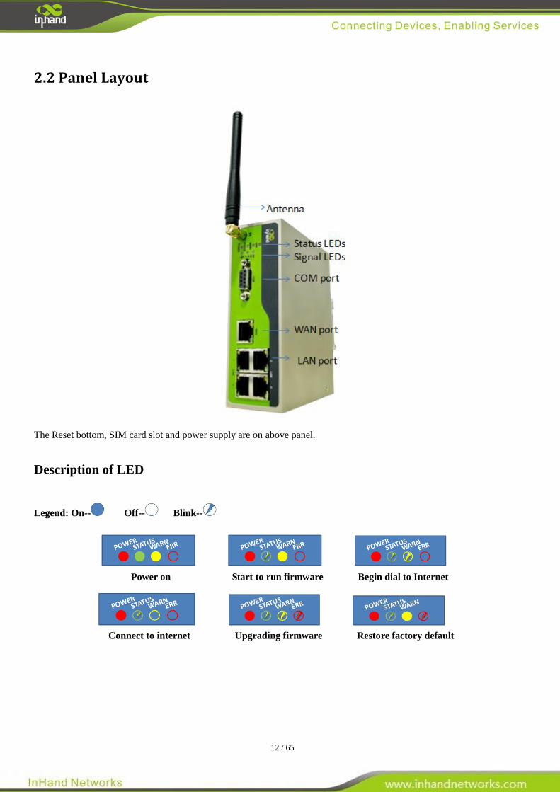
2.2 Panel Layout
The Reset bottom, SIM card slot and power supply are on above panel.
Description of LED
Legend: On-- Off-- Blink--
Power on Start to run firmware Begin dial to Internet
Connect to internet Upgrading firmware Restore factory default

13 / 65
Signal Status LED Description
----- Signal: 1-9 (poor signal level, router cannot work, please check the antenna and local signal level)
------ Signal: 10-19 (Router can work under this signal level)
------ Signal: 20-31 (Perfect signal level)
14 / 65
2.3 Quick Connection to Internet
2.3.1 Insert SIM Card
Open InRouter SIM/UIM card case at the bottom, insert the SIM card and close the case.
2.3.2 Antenna Installation
After install the IR6x5, connect the interface of enhanced antenna to the interface of skin antenna and screw tightly. Put
the amplifier of enhanced antenna to where it can receive the signal well.
Attention: Position and angle of the antenna may influence the quality of signal.
2.3.3 Power Supply
Connect InRouter to power supply with the power supply cord in the package, observe whether the Power LED on the
panel of InRouter goes on. If not, please contact InHand for technical support.
You can start to configure IR6X1 after the Power LED turns on.
2.3.4 Connect
Link IR6x5 with PC:
(1) Using a cable to link IR6x5 with a PC;
(2) After the connection, you can see one LED of RJ45 Interface turns green and the other flashes.
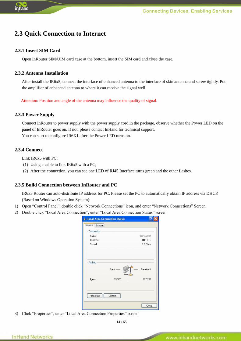
2.3.5 Build Connection between InRouter and PC
IR6x5 Router can auto-distribute IP address for PC. Please set the PC to automatically obtain IP address via DHCP.
(Based on Windows Operation System):
1) Open “Control Panel”, double click “Network Connections” icon, and enter “Network Connections” Screen.
2) Double click “Local Area Connection”, enter “Local Area Connection Status” screen:
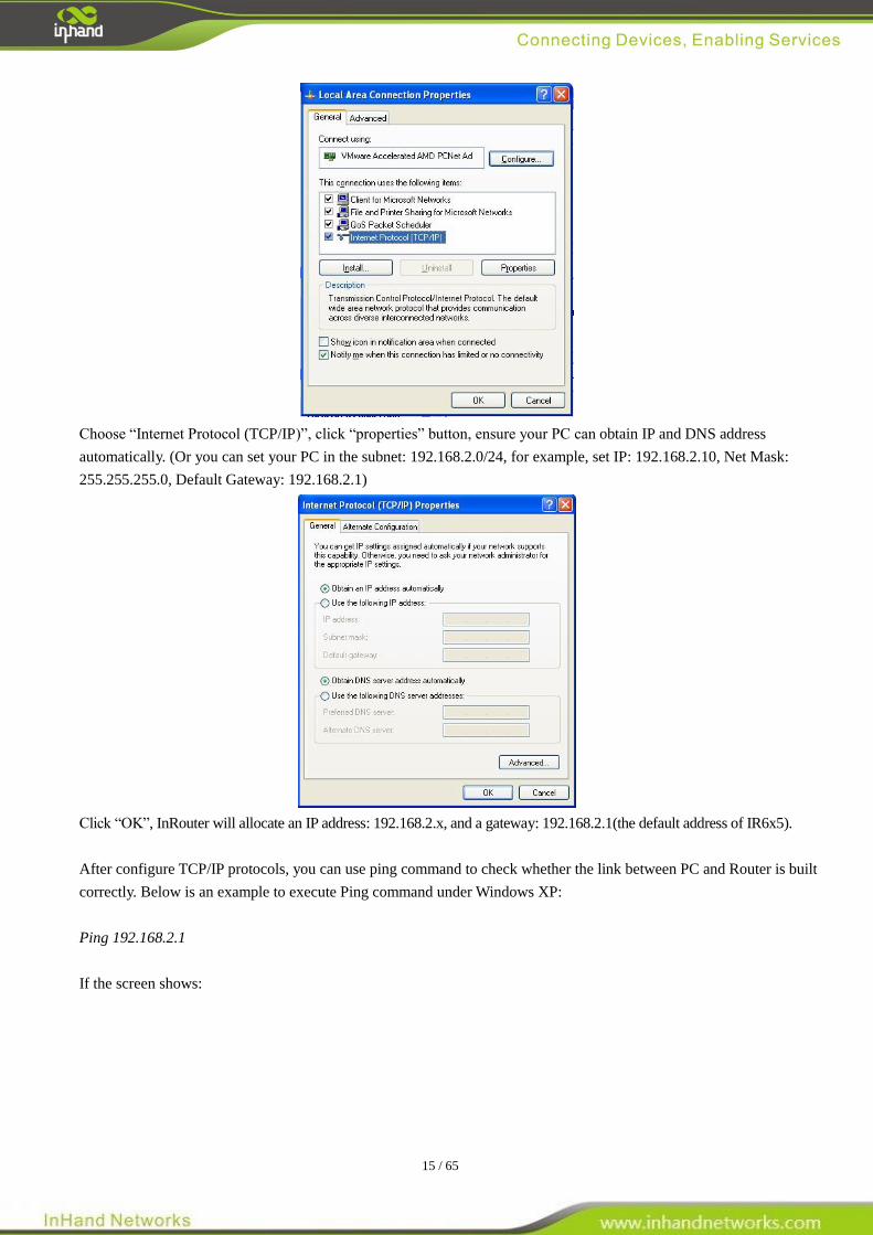
3) Click “Properties”, enter “Local Area Connection Properties” screen
15 / 65
Choose “Internet Protocol (TCP/IP)”, click “properties” button, ensure your PC can obtain IP and DNS address
automatically. (Or you can set your PC in the subnet: 192.168.2.0/24, for example, set IP: 192.168.2.10, Net Mask:
255.255.255.0, Default Gateway: 192.168.2.1)
Click “OK”, InRouter will allocate an IP address: 192.168.2.x, and a gateway: 192.168.2.1(the default address of IR6x5).
After configure TCP/IP protocols, you can use ping command to check whether the link between PC and Router is built
correctly. Below is an example to execute Ping command under Windows XP:
Ping 192.168.2.1
If the screen shows:
16 / 65
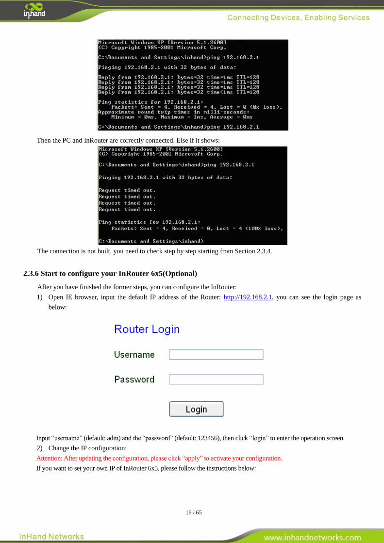
Then the PC and InRouter are correctly connected. Else if it shows:
The connection is not built, you need to check step by step starting from Section 2.3.4.
2.3.6 Start to configure your InRouter 6x5(Optional)
After you have finished the former steps, you can configure the InRouter:
1) Open IE browser, input the default IP address of the Router: http://192.168.2.1, you can see the login page as
below:
Input “username” (default: adm) and the “password” (default: 123456), then click “login” to enter the operation screen.
2) Change the IP configuration:
Attention: After updating the configuration, please click “apply” to activate your configuration.
If you want to set your own IP of InRouter 6x5, please follow the instructions below:
17 / 65
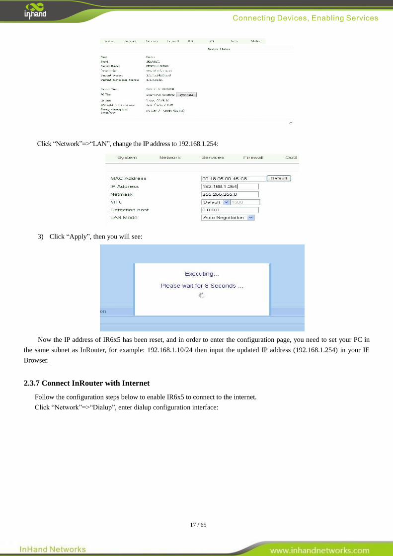
Click “Network”=>“LAN”, change the IP address to 192.168.1.254:
3) Click “Apply”, then you will see:
Now the IP address of IR6x5 has been reset, and in order to enter the configuration page, you need to set your PC in
the same subnet as InRouter, for example: 192.168.1.10/24 then input the updated IP address (192.168.1.254) in your IE
Browser.
2.3.7 Connect InRouter with Internet
Follow the configuration steps below to enable IR6x5 to connect to the internet.
Click “Network”=>“Dialup”, enter dialup configuration interface:
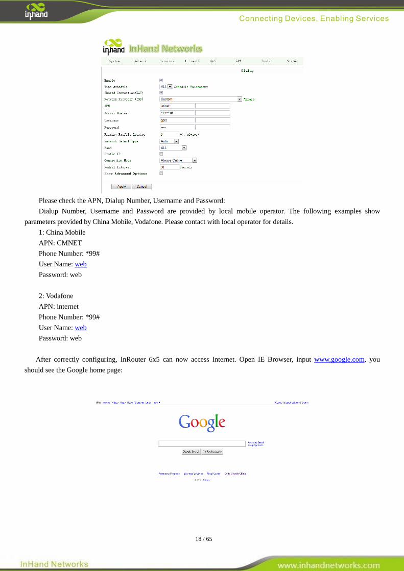
18 / 65
Please check the APN, Dialup Number, Username and Password:
Dialup Number, Username and Password are provided by local mobile operator. The following examples show
parameters provided by China Mobile, Vodafone. Please contact with local operator for details.
1: China Mobile
APN: CMNET
Phone Number: *99#
User Name: web
Password: web
2: Vodafone
APN: internet
Phone Number: *99#
User Name: web
Password: web
After correctly configuring, InRouter 6x5 can now access Internet. Open IE Browser, input www.google.com, you
should see the Google home page:
19 / 65
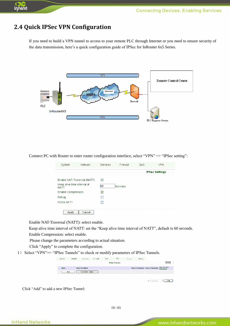
2.4 Quick IPSec VPN Configuration
If you need to build a VPN tunnel to access to your remote PLC through Internet or you need to ensure security of
the data transmission, here’s a quick configuration guide of IPSec for InRouter 6x5 Series.
Connect PC with Router to enter router configuration interface, select “VPN” => “IPSec setting”:
Enable NAT-Traversal (NATT): select enable.
Keep alive time interval of NATT: set the “Keep alive time interval of NATT”, default is 60 seconds.
Enable Compression: select enable.
Please change the parameters according to actual situation.
Click “Apply” to complete the configuration.
1) Select “VPN”=> “IPSec Tunnels” to check or modify parameters of IPSec Tunnels.
Click “Add” to add a new IPSec Tunnel:
20 / 65
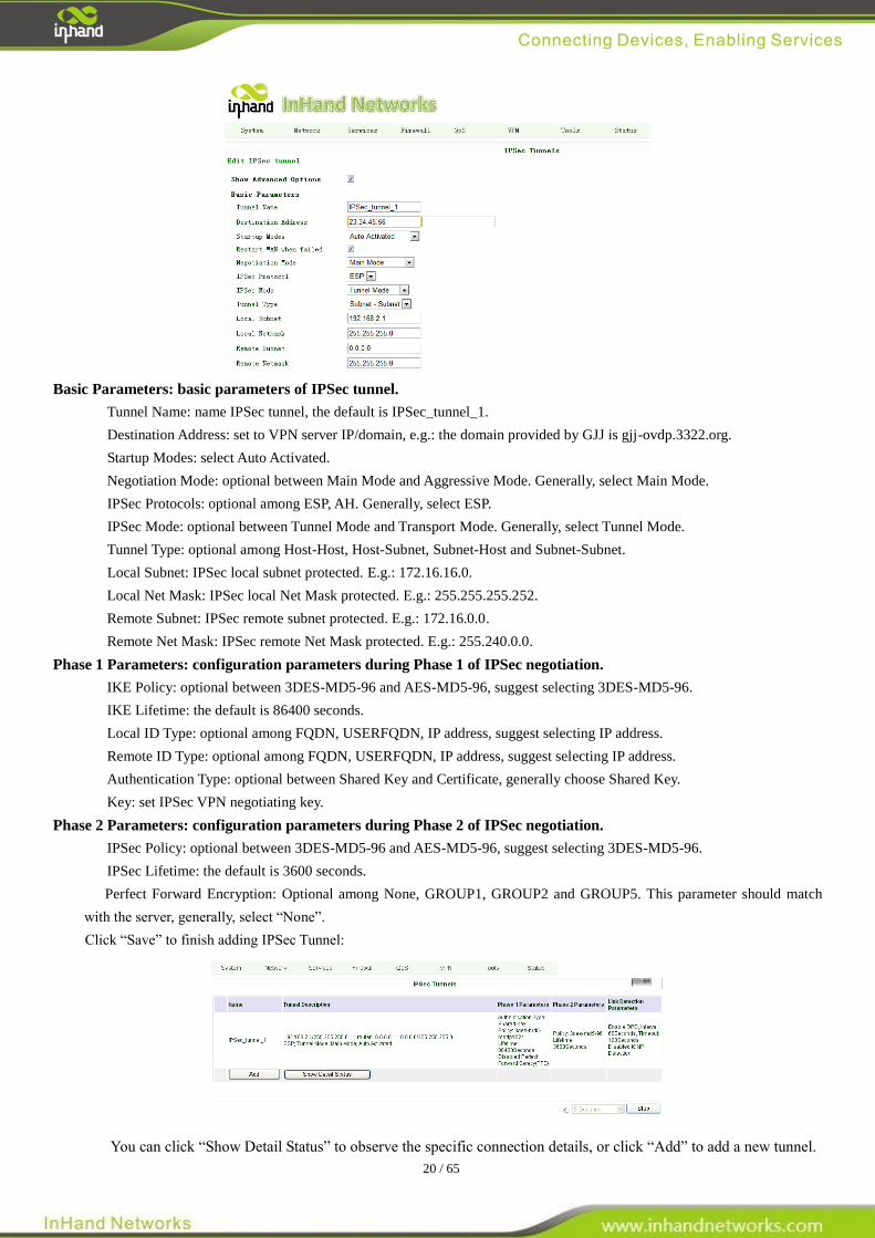
Basic Parameters: basic parameters of IPSec tunnel.
Tunnel Name: name IPSec tunnel, the default is IPSec_tunnel_1.
Destination Address: set to VPN server IP/domain, e.g.: the domain provided by GJJ is gjj-ovdp.3322.org.
Startup Modes: select Auto Activated.
Negotiation Mode: optional between Main Mode and Aggressive Mode. Generally, select Main Mode.
IPSec Protocols: optional among ESP, AH. Generally, select ESP.
IPSec Mode: optional between Tunnel Mode and Transport Mode. Generally, select Tunnel Mode.
Tunnel Type: optional among Host-Host, Host-Subnet, Subnet-Host and Subnet-Subnet.
Local Subnet: IPSec local subnet protected. E.g.: 172.16.16.0.
Local Net Mask: IPSec local Net Mask protected. E.g.: 255.255.255.252.
Remote Subnet: IPSec remote subnet protected. E.g.: 172.16.0.0.
Remote Net Mask: IPSec remote Net Mask protected. E.g.: 255.240.0.0.
Phase 1 Parameters: configuration parameters during Phase 1 of IPSec negotiation.
IKE Policy: optional between 3DES-MD5-96 and AES-MD5-96, suggest selecting 3DES-MD5-96.
IKE Lifetime: the default is 86400 seconds.
Local ID Type: optional among FQDN, USERFQDN, IP address, suggest selecting IP address.
Remote ID Type: optional among FQDN, USERFQDN, IP address, suggest selecting IP address.
Authentication Type: optional between Shared Key and Certificate, generally choose Shared Key.
Key: set IPSec VPN negotiating key.
Phase 2 Parameters: configuration parameters during Phase 2 of IPSec negotiation.
IPSec Policy: optional between 3DES-MD5-96 and AES-MD5-96, suggest selecting 3DES-MD5-96.
IPSec Lifetime: the default is 3600 seconds.
Perfect Forward Encryption: Optional among None, GROUP1, GROUP2 and GROUP5. This parameter should match
with the server, generally, select “None”.
Click “Save” to finish adding IPSec Tunnel:
You can click “Show Detail Status” to observe the specific connection details, or click “Add” to add a new tunnel.
21 / 65
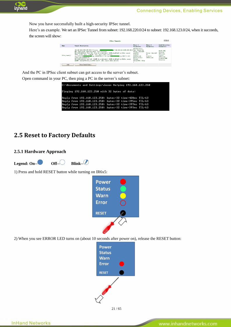
Now you have successfully built a high-security IPSec tunnel.
Here’s an example. We set an IPSec Tunnel from subnet: 192.168.220.0/24 to subnet: 192.168.123.0/24, when it succeeds,
the screen will show:
And the PC in IPSec client subnet can get access to the server’s subnet.
Open command in your PC, then ping a PC in the server’s subnet:
2.5 Reset to Factory Defaults
2.5.1 Hardware Approach
Legend: On-- Off-- Blink--
1) Press and hold RESET button while turning on IR6x5:
2) When you see ERROR LED turns on (about 10 seconds after power on), release the RESET button:
22 / 65
3) After a few seconds, the ERROR LED will turn off, now press RESET button again:
4) Then you will see ERROR and STATUS LED blink, which means reset to factory defaults succeed!
Factory default settings:
IP: 192.168.2.1
Net Mask: 255.255.255.0
Serial parameter: 19200-8-N-1
2.5.2 Web Approach
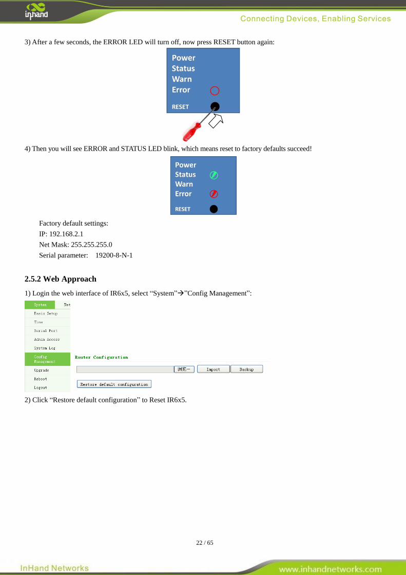
1) Login the web interface of IR6x5, select “System””Config Management”:
2) Click “Restore default configuration” to Reset IR6x5.
23 / 65
III
Advanced Configuration
◆ Configuration on Web
◆ CLI Configuration
3.1 Configuration on Web
InRouter must be correctly configured before use. This chapter will show you how to configure InRouer via Web
interface.
3.1.1 Preparation
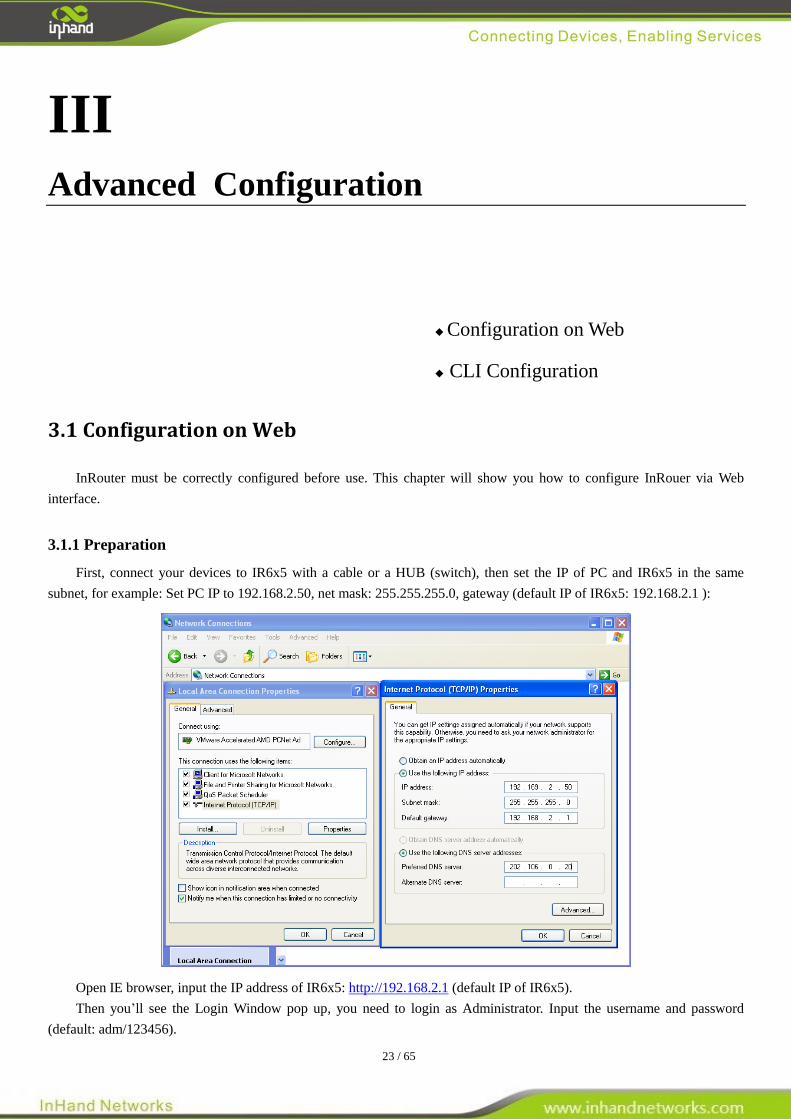
First, connect your devices to IR6x5 with a cable or a HUB (switch), then set the IP of PC and IR6x5 in the same
subnet, for example: Set PC IP to 192.168.2.50, net mask: 255.255.255.0, gateway (default IP of IR6x5: 192.168.2.1 ):
Open IE browser, input the IP address of IR6x5: http://192.168.2.1 (default IP of IR6x5).
Then you’ll see the Login Window pop up, you need to login as Administrator. Input the username and password
(default: adm/123456).
24 / 65
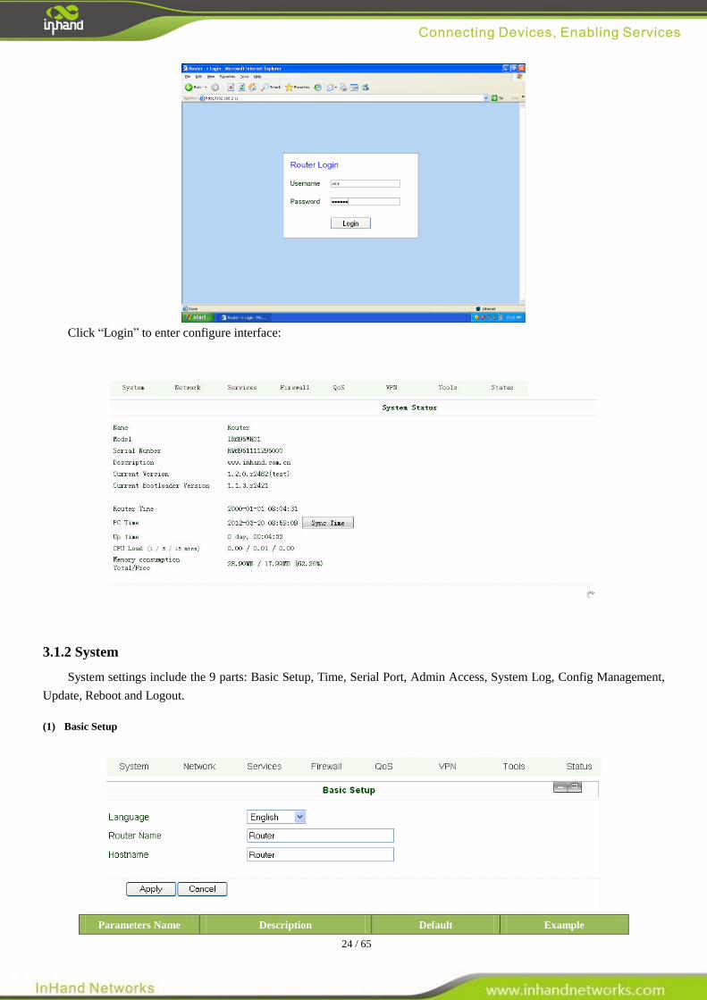
Click “Login” to enter configure interface:
3.1.2 System
System settings include the 9 parts: Basic Setup, Time, Serial Port, Admin Access, System Log, Config Management,
Update, Reboot and Logout.
(1) Basic Setup
Parameters Name Description Default Example

25 / 65
Language Choose language of configuration web Chinese English
Router Name Set name of InRouter Router My InRouter
Host Name Name the device/PC linked with IR6x5 Router My InRouter
(2) Time
Name Description Default
Router Time Display router time 2000-01-01 8:00:00
PC Time Display PC time (or the time of device linked with
router)
Time Zone Set time zone Custom
Custom TZ string Set the string of time zone of Router CST-8
Auto Update Time Time Update Interval Disabled
NTP Time Servers (after enable the
Auto Update Time)
Setting for NTP Time server. (Three at the most) pool.ntp.org
(3) Serial Port
Name Description Default
Baud Rate Serial baud rate 19200
Data Bit Serial data bits 8
Parity Set parity bit of serial data. None
Stop Bit Set stop bit of serial data. 1
Hardware Flow Control Enable Hardware Flow Control Disable
Software Flow Control Enable Software Flow Control Disable
26 / 65
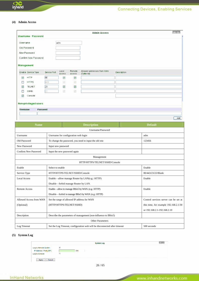
(4) Admin Access
Name Description Default
Username/Password
Username Username for configuration web login adm
Old Password To change the password, you need to input the old one 123456
New Password Input new password
Confirm New Password Input the new password again
Management
HTTP/HTTPS/TELNET/SSHD/Console
Enable Select to enable Enable
Service Type HTTP/HTTPS/TELNET/SSHD/Console 80/443/23/22/Blank
Local Access Enable—allow manage Router by LAN(e.g.: HTTP)
Disable—forbid manage Router by LAN.
Enable
Remote Access Enable—allow to manage IR6x5 by WAN. (e.g.: HTTP)
Disable—forbid to manage IR6x5 by WAN. (e.g.: HTTP)
Enable
Allowed Access from WAN
(Optional)
Set the range of allowed IP address for WAN
(HTTP/HTTPS/TELNET/SSHD)
Control services server can be set at
this time, for example 192.168.2.1/30
or 192.168.2.1-192.168.2.10
Description Describe the parameters of management (non-influence to IR6x5)
Other Parameters
Log Timeout Set the Log Timeout, configuration web will be disconnected after timeout 500 seconds
(5) System Log
27 / 65
Name Description Default
Log to Remote System Enable remote log server Disable
IP address/Port (UDP) Set the IP and Port of remote log server Port: 514
Log to Console Enable remote log server Disable
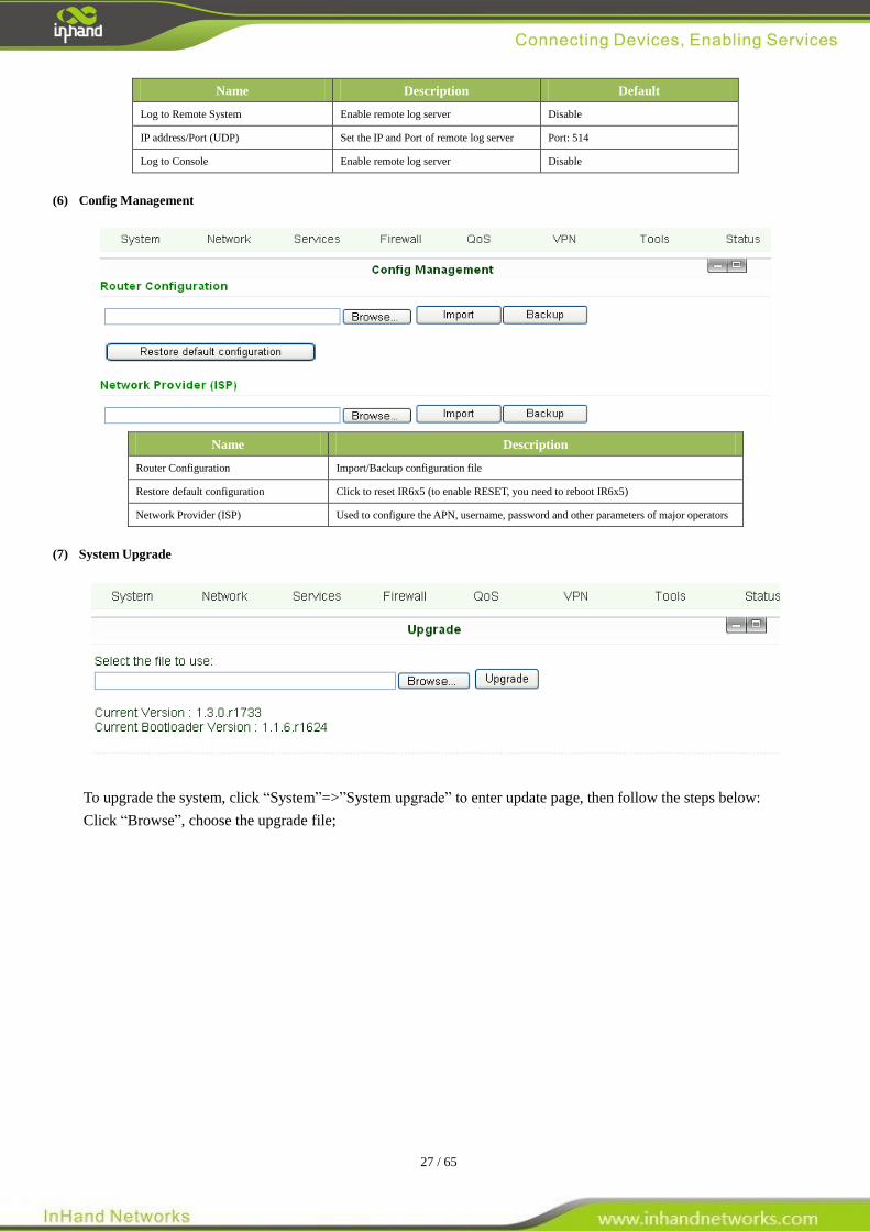
(6) Config Management
Name Description
Router Configuration Import/Backup configuration file
Restore default configuration Click to reset IR6x5 (to enable RESET, you need to reboot IR6x5)
Network Provider (ISP) Used to configure the APN, username, password and other parameters of major operators
(7) System Upgrade
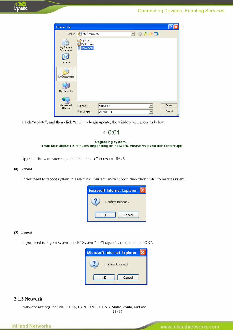
To upgrade the system, click “System”=>”System upgrade” to enter update page, then follow the steps below:
Click “Browse”, choose the upgrade file;
28 / 65
Click “update”, and then click “sure” to begin update, the window will show as below.
Upgrade firmware succeed, and click “reboot” to restart IR6x5.
(8) Reboot
If you need to reboot system, please click ”System”=>”Reboot”, then click ”OK” to restart system.
(9) Logout
If you need to logout system, click “System”=>”Logout”, and then click “OK”.
3.1.3 Network
Network settings include Dialup, LAN, DNS, DDNS, Static Route, and etc.
29 / 65
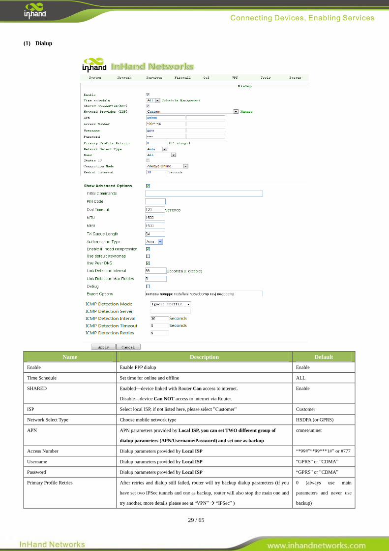
(1) Dialup
Name Description Default
Enable Enable PPP dialup Enable
Time Schedule Set time for online and offline ALL
SHARED Enabled—device linked with Router Can access to internet.
Disable—device Can NOT access to internet via Router.
Enable
ISP Select local ISP, if not listed here, please select ”Customer” Customer
Network Select Type Choose mobile network type HSDPA (or GPRS)
APN APN parameters provided by Local ISP, you can set TWO different group of
dialup parameters (APN/Username/Password) and set one as backup
cmnet/uninet
Access Number Dialup parameters provided by Local ISP “*99#”“*99***1#” or #777
Username Dialup parameters provided by Local ISP “GPRS” or ”CDMA”
Password Dialup parameters provided by Local ISP “GPRS” or ”CDMA”
Primary Profile Retries After retries and dialup still failed, router will try backup dialup parameters (if you
have set two IPSec tunnels and one as backup, router will also stop the main one and
try another, more details please see at “VPN” “IPSec” )
0 (always use main
parameters and never use
backup)
30 / 65
Static IP Enable Static IP if your SIM card can get static IP address Disable
Connection Mode Optional Always Online, Always Online
Redial Interval When Dial fails, InRouter will redial after the interval 30 seconds
Show Advanced Options Enable configure advanced options Disabled
Initial Commands Used for advanced parameters Blank
Dial Timeout Set dial timeout (IR700 will reboot after timeout) 120 seconds
MTU Set max transmit unit 1500
MRU Set max receive unit 1500
TX Queue Length Set length of transmit queue 3
Enable IP header compression Enable IP header compression Disabled
Use default asyncmap Enable default asyncmap, PPP advanced option Disabled
Using Peer DNS Click Enable to accept the peer DNS Enabled
Link Detection Interval Set Link Detection Interval 30 seconds
Link Detection Max Retries Set the max retries if link detection failed 3
Debug Enable debug mode Enable
Expert Option Provide extra PPP parameters, normally user needn’t set this. Blank
ICMP Detection Mode
MONITOR TRAFFIC
When InRouter detected there are “business” data (DTU, IPSec) receive or transmit, InRouter
will not send ICMP probe packet. When detected without business data, InRouter will send
ICPM probe packet
Ignore Traffic
IGNORE TRAFFIC
No matter whether InRouter have some data receive or transmit(DUT, IPSec data), InRouter
always send the ICMP probe packet.
HANDOVER ONLY
InRouter send the ICMP probe Packet when the field change from a base station to other
station.
ICMP Detection Server Set ICMP Detection Server, blank represents none Blank
ICMP Detection Interval Set ICMP Detection Interval 30 seconds
ICMP Detection Timeout Set ICMP Detection Timeout (IR700 will reboot if ICMP time out) 5 seconds
ICMP Detection Max Retries Set the max number of retries if ICMP failed 5
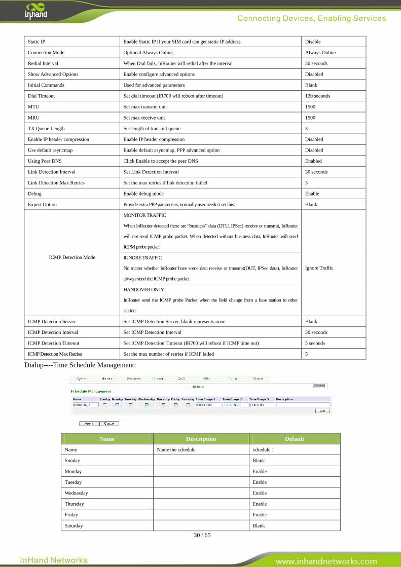
Dialup----Time Schedule Management:
Name Description Default
Name Name the schedule schedule 1
Sunday Blank
Monday Enable
Tuesday Enable
Wednesday Enable
Thursday Enable
Friday Enable
Saturday Blank
31 / 65
Time Range 1 Set Time Range 1 9:00-12:00
Time Range 2 Set Time Range 2 14:00-18:00
Time Range 3 Set Time Range 3 0:00-0:00
Description Describe configuration Blank
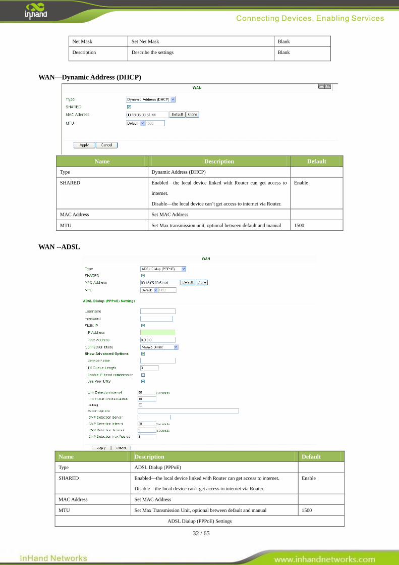
(2) WAN
This page is to set the type of WAN port:
Name Description Default
Type Static IP;
Dynamic Address(DHCP);
ADSL Dialup(PPPoE);
Disabled
Disabled
Attention: There can only be one WAN type at one time, enabling one type WAN will disabled another.
WAN—Static IP
Name Description Default
Type Static IP
SHARED Enabled—the local device linked with Router can get access to
internet.
Disable—the local device can’t get access to internet via Router.
Enable
MAC Address Set MAC Address
IP Address Set WAN port IP 192.168.1.29
Net Mask Set WAN port Net Mask 255.255.255.0
Gateway Set WAN Gateway 192.168.1.1
MTU Set Max Transmission Unit, optional between default and manual 1500
Multi-IP Settings(can set 8 additional IP address at the most)
IP address Set the additional IP address of LAN Blank
32 / 65
Net Mask Set Net Mask Blank
Description Describe the settings Blank
WAN—Dynamic Address (DHCP)
Name Description Default
Type Dynamic Address (DHCP)
SHARED Enabled—the local device linked with Router can get access to
internet.
Disable—the local device can’t get access to internet via Router.
Enable
MAC Address Set MAC Address
MTU Set Max transmission unit, optional between default and manual 1500
WAN --ADSL
Name Description Default
Type ADSL Dialup (PPPoE)
SHARED Enabled—the local device linked with Router can get access to internet.
Disable—the local device can’t get access to internet via Router.
Enable
MAC Address Set MAC Address
MTU Set Max Transmission Unit, optional between default and manual 1500
ADSL Dialup (PPPoE) Settings
33 / 65
Username Set username for dialing up Blank
Password Set password for dialing up Blank
Static IP Enable Static IP Disabled
IP address Static IP Address Blank
Peer IP Set Peer IP Blank
Connection Mode Set connection mode (Connect on Demand/Always Online/ Manual) Always Online
Advanced Options
Show advanced options Enable advanced configuration Disabled
Service Name Name the service Blank
TX Queue Length Set TX Queue Length 3
Enable IP head compression Click to enable IP head compression Disabled
User Peer DNS Enable User Peer DNS Disabled
Link Detection Interval Set link detection interval 55 seconds
Link Detection Max Retries Set link detection max retries 10 (times)
Debug Select to enable debug-mode Disabled
Expert Options Set expert parameters Blank
ICMP Detection Server Set ICMP Detection Server Blank
ICMP Detection Time Set ICMP Detection Time 30
ICMP Detection Timeout Set ICMP Detection Timeout 3
ICMP Detection Max Reties Set ICMP Detection Max Reties 3
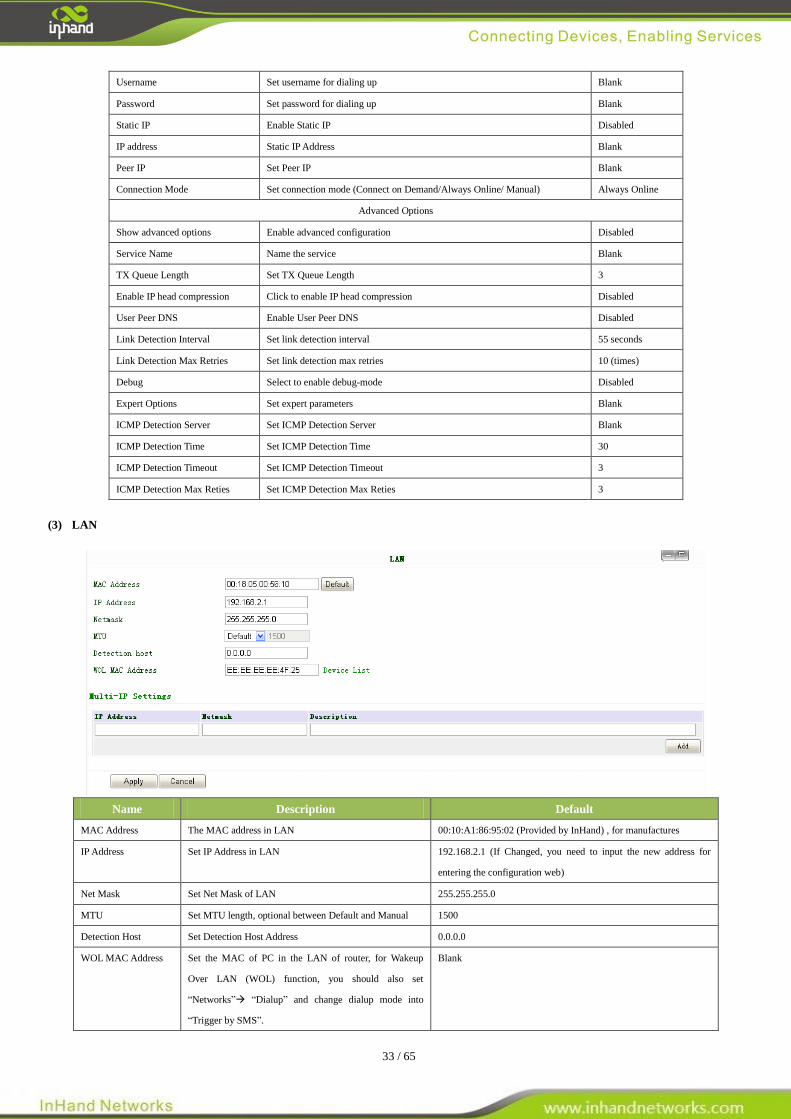
(3) LAN
Name Description Default
MAC Address The MAC address in LAN 00:10:A1:86:95:02 (Provided by InHand) , for manufactures
IP Address Set IP Address in LAN 192.168.2.1 (If Changed, you need to input the new address for
entering the configuration web)
Net Mask Set Net Mask of LAN 255.255.255.0
MTU Set MTU length, optional between Default and Manual 1500
Detection Host Set Detection Host Address 0.0.0.0
WOL MAC Address Set the MAC of PC in the LAN of router, for Wakeup
Over LAN (WOL) function, you should also set
“Networks” “Dialup” and change dialup mode into
“Trigger by SMS”.
Blank
34 / 65
Multi-IP Settings (Support additional 8 IP addresses at the most)
IP Address Set additional IP Address of LAN Blank
Description Description about this IP address Blank
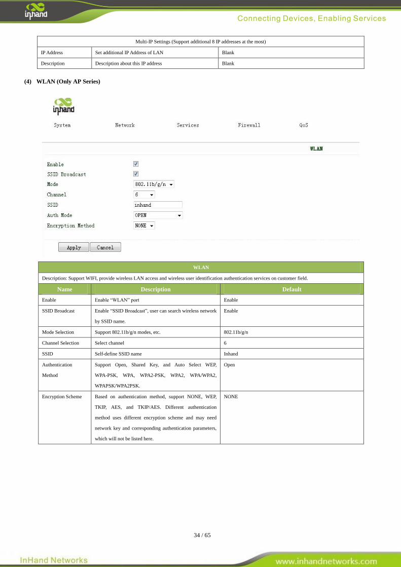
(4) WLAN (Only AP Series)
WLAN
Description: Support WIFI, provide wireless LAN access and wireless user identification authentication services on customer field.
Name Description Default
Enable Enable “WLAN” port Enable
SSID Broadcast Enable “SSID Broadcast”, user can search wireless network
by SSID name.
Enable
Mode Selection Support 802.11b/g/n modes, etc. 802.11b/g/n
Channel Selection Select channel 6
SSID Self-define SSID name Inhand
Authentication
Method
Support Open, Shared Key, and Auto Select WEP,
WPA-PSK, WPA, WPA2-PSK, WPA2, WPA/WPA2,
WPAPSK/WPA2PSK.
Open
Encryption Scheme Based on authentication method, support NONE, WEP,
TKIP, AES, and TKIP/AES. Different authentication
method uses different encryption scheme and may need
network key and corresponding authentication parameters,
which will not be listed here.
NONE
35 / 65
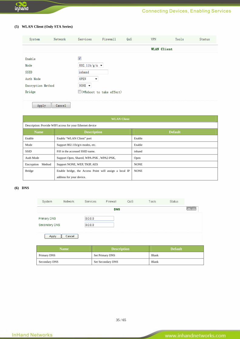
(5) WLAN Client (Only STA Series)
WLAN Client
Description: Provide WIFI access for your Ethernet device
Name Description Default
Enable Enable “WLAN Client” port Enable
Mode Support 802.11b/g/n modes, etc. Enable
SSID Fill in the accessed SSID name. inhand
Auth Mode Support Open, Shared, WPA-PSK , WPA2-PSK, Open
Encryption Method Support NONE, WEP, TKIP, AES NONE
Bridge Enable bridge, the Access Point will assign a local IP
address for your device.
NONE
(6) DNS
Name Description Default
Primary DNS Set Primary DNS Blank
Secondary DNS Set Secondary DNS Blank
36 / 65
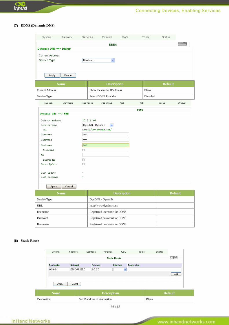
(7) DDNS (Dynamic DNS)
Name Description Default
Current Address Show the current IP address Blank
Service Type Select DDNS Provider Disabled
Name Description Default
Service Type DynDNS - Dynamic
URL http://www.dyndns.com/
Username Registered username for DDNS
Password Registered password for DDNS
Hostname Registered hostname for DDNS
(8) Static Route
Name Description Default
Destination Set IP address of destination Blank
37 / 65
Net Mask Set subnet Mask of destination 255.255.255.0
Gateway Set the gateway of destination Blank
Interface Optional LAN/WAN port access to destination Blank
Description Describe static route Blank
3.1.4 Service
Service settings include DHCP Service, DNS Forwarding, VRRP and other related parameters.
(1) DHCP Service
Name Description Default
Enable DHCP Click to enable DHCP Enable
IP Pool Starting Address Set the starting IP address of DHCP pool 192.168.2.2
IP Pool Ending Address Set the ending IP address of DHCP pool 192.168.2.100
Lease Set the valid time lease of IP address
obtained by DHCP
60 minutes
DNS Set DNS Server 192.168.2.1
Windows Name Server
(WINS)
Set WINS Blank
Static DHCP (can set 20 designated IP address at the most)
MAC Address Set the MAC address of a designated IP
address
Blank
IP address Set the static IP address 192.168.2.2
Host Set the hostname Blank
(2) DNS Relay
Name Description Default
Enable DNS Relay Click to enable DNS Relay Disabled
Designate IP address<=>DNS couples (20 at the most)
IP Address Set IP address <=> DNS couples Blank
38 / 65
Host Set the name of IP address <=> DNS couples Blank
Description Describe IP address <=> DNS couples Blank
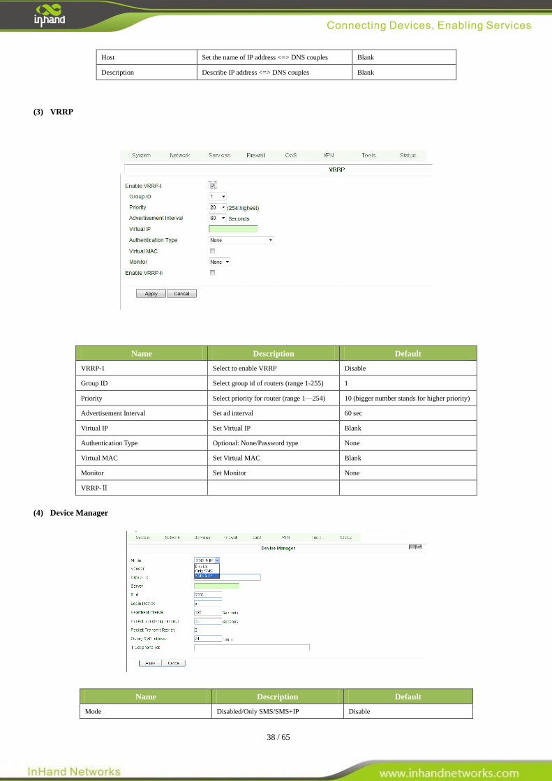
(3) VRRP
Name Description Default
VRRP-1 Select to enable VRRP Disable
Group ID Select group id of routers (range 1-255) 1
Priority Select priority for router (range 1—254) 10 (bigger number stands for higher priority)
Advertisement Interval Set ad interval 60 sec
Virtual IP Set Virtual IP Blank
Authentication Type Optional: None/Password type None
Virtual MAC Set Virtual MAC Blank
Monitor Set Monitor None
VRRP-Ⅱ
(4) Device Manager
Name Description Default
Mode Disabled/Only SMS/SMS+IP Disable
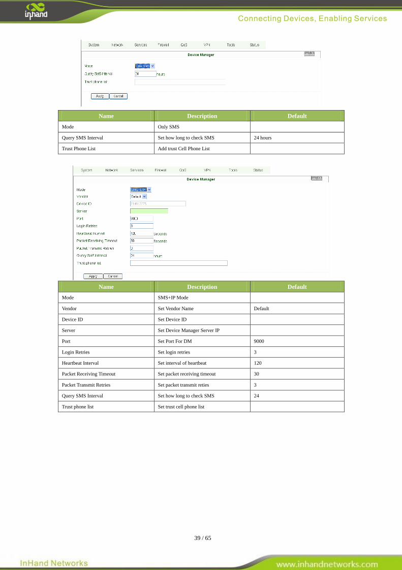
39 / 65
Name Description Default
Mode Only SMS
Query SMS Interval Set how long to check SMS 24 hours
Trust Phone List Add trust Cell Phone List
Name Description Default
Mode SMS+IP Mode
Vendor Set Vendor Name Default
Device ID Set Device ID
Server Set Device Manager Server IP
Port Set Port For DM 9000
Login Retries Set login retries 3
Heartbeat Interval Set interval of heartbeat 120
Packet Receiving Timeout Set packet receiving timeout 30
Packet Transmit Retries Set packet transmit reties 3
Query SMS Interval Set how long to check SMS 24
Trust phone list Set trust cell phone list
40 / 65
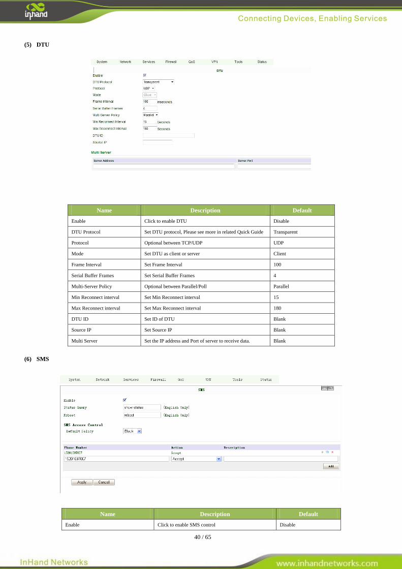
(5) DTU
Name Description Default
Enable Click to enable DTU Disable
DTU Protocol Set DTU protocol, Please see more in related Quick Guide Transparent
Protocol Optional between TCP/UDP UDP
Mode Set DTU as client or server Client
Frame Interval Set Frame Interval 100
Serial Buffer Frames Set Serial Buffer Frames 4
Multi-Server Policy Optional between Parallel/Poll Parallel
Min Reconnect interval Set Min Reconnect interval 15
Max Reconnect interval Set Max Reconnect interval 180
DTU ID Set ID of DTU Blank
Source IP Set Source IP Blank
Multi Server Set the IP address and Port of server to receive data. Blank
(6) SMS
Name Description Default
Enable Click to enable SMS control Disable
41 / 65
Status Query Set Status Query SMS, and you can see status of router
by send SMS (e.g.: show status).
Reboot Let the router reboot
SMS Access Control
Default Policy Block or Accept control SMS from certain Phone Block
Phone List Include phone numbers accepted or blocked to send
SMS to router
Notice: Before using this function, please make sure you have a SIM card in the InRouter that has SMS function.
Otherwise, please contact local mobile operator to get one.
SMS you will get in your mobile phone:
Host: (SN);
Uptime: (the uptime of router for this time of reboot);
State: (Online/Offline) (Cellular WAN IP)
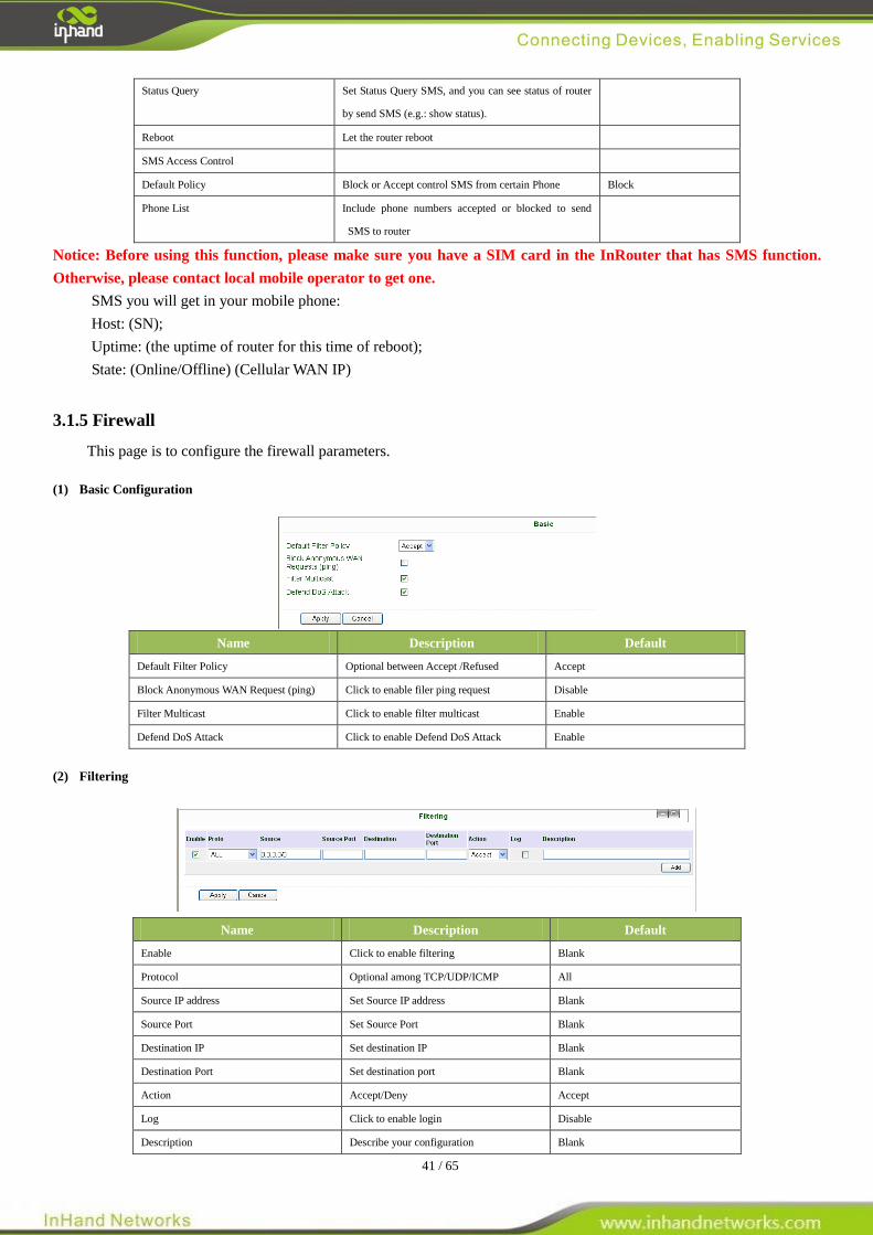
3.1.5 Firewall
This page is to configure the firewall parameters.
(1) Basic Configuration
Name Description Default
Default Filter Policy Optional between Accept /Refused Accept
Block Anonymous WAN Request (ping) Click to enable filer ping request Disable
Filter Multicast Click to enable filter multicast Enable
Defend DoS Attack Click to enable Defend DoS Attack Enable
(2) Filtering
Name Description Default
Enable Click to enable filtering Blank
Protocol Optional among TCP/UDP/ICMP All
Source IP address Set Source IP address Blank
Source Port Set Source Port Blank
Destination IP Set destination IP Blank
Destination Port Set destination port Blank
Action Accept/Deny Accept
Log Click to enable login Disable
Description Describe your configuration Blank
42 / 65
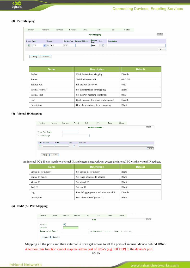
(3) Port Mapping
Name Description Default
Enable Click Enable Port Mapping Disable
Source To fill with source IP 0.0.0.0/0
Service Port Fill the port of service 8080
Internal Address Set the internal IP for mapping Blank
Internal Port Set the Port mapping to internal 8080
Log Click to enable log about port mapping. Disable
Description Describe meanings of each mapping Blank
(4) Virtual IP Mapping
An internal PC’s IP can match to a virtual IP, and external network can access the internal PC via this virtual IP address.
Name Description Default
Virtual IP for Router Set Virtual IP for Router Blank
Source IP Range Set range of source IP address Blank
Virtual IP Set virtual IP Blank
Real IP Set real IP Blank
Log Enable logging concerned with virtual IP Disable
Description Describe this configuration Blank
(5) DMZ (All Port Mapping)
Mapping all the ports and then external PC can get access to all the ports of internal device behind IR6x5.
Attention: this function cannot map the admin port of IR6x5 (e.g.: 80 TCP) to the device’s port.
43 / 65
Name Description Default
Enable DMZ Click to Enable DMZ Disable
DMZ Host Set host IP of DMZ Blank
Source Address Range Set IP address with restrict IP access Blank
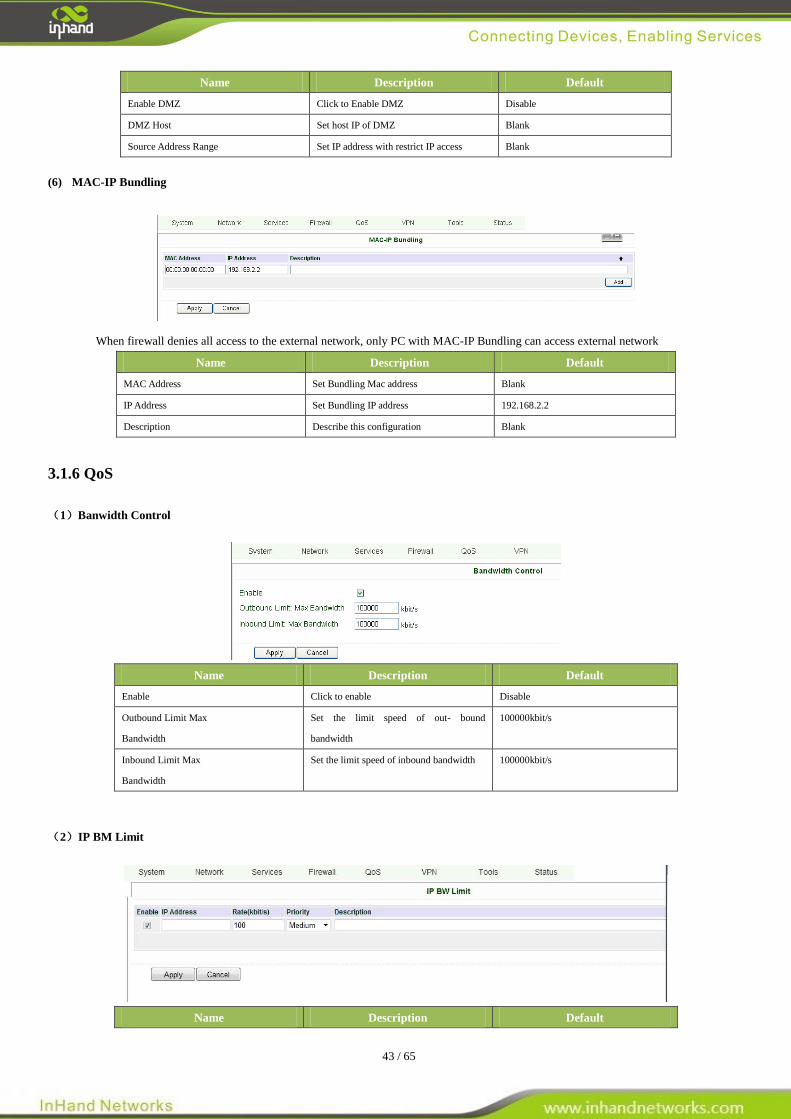
(6) MAC-IP Bundling
When firewall denies all access to the external network, only PC with MAC-IP Bundling can access external network
Name Description Default
MAC Address Set Bundling Mac address Blank
IP Address Set Bundling IP address 192.168.2.2
Description Describe this configuration Blank
3.1.6 QoS
(1)Banwidth Control
Name Description Default
Enable Click to enable Disable
Outbound Limit Max
Bandwidth
Set the limit speed of out- bound
bandwidth
100000kbit/s
Inbound Limit Max
Bandwidth
Set the limit speed of inbound bandwidth 100000kbit/s
(2)IP BM Limit
Name Description Default
44 / 65
Enable Click to enable Disable
IP Address Set IP Address Blank
Rate Set Rate 100 kbit/s
Priority Set the Priority Medum
Description Describe this configuration Blank
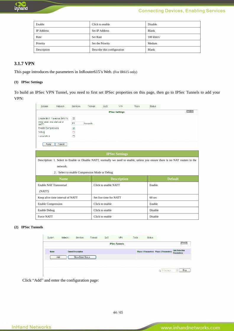
3.1.7 VPN
This page introduces the parameters in InRouter615’s Web. (For IR615 only)
(1) IPSec Settings
To build an IPSec VPN Tunnel, you need to first set IPSec properties on this page, then go to IPSec Tunnels to add your
VPN:
IPSec Settings
Description: 1. Select to Enable or Disable NATT, normally we need to enable, unless you ensure there is no NAT routers in the
network.
2.Select to enable Compression Mode or Debug
Name Description Default
Enable NAT Transversal
(NATT)
Click to enable NATT Enable
Keep alive time interval of NATT Set live time for NATT 60 sec
Enable Compression Click to enable Enable
Enable Debug Click to enable Disable
Force NATT Click to enable Disable
(2) IPSec Tunnels
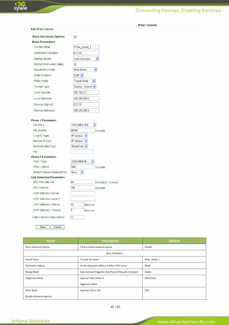
Click “Add” and enter the configuration page:
45 / 65
Name Description Default
Show Advanced Options Click to enable advanced options Disable
Basic Parameters
Tunnel Name To name the tunnel IPSec_tunnel_1
Destination Address Set the destination address of IPSec VPN Server Blank
Startup Mode Auto Activate/Trigged by Data/Passive/Manually Activated Enable
Negotiation Mode Optional: Main Mode or
Aggressive Mode
Main Mode
IPSec Mode
(Enable Advanced options)
Optional: ESP or AH ESP
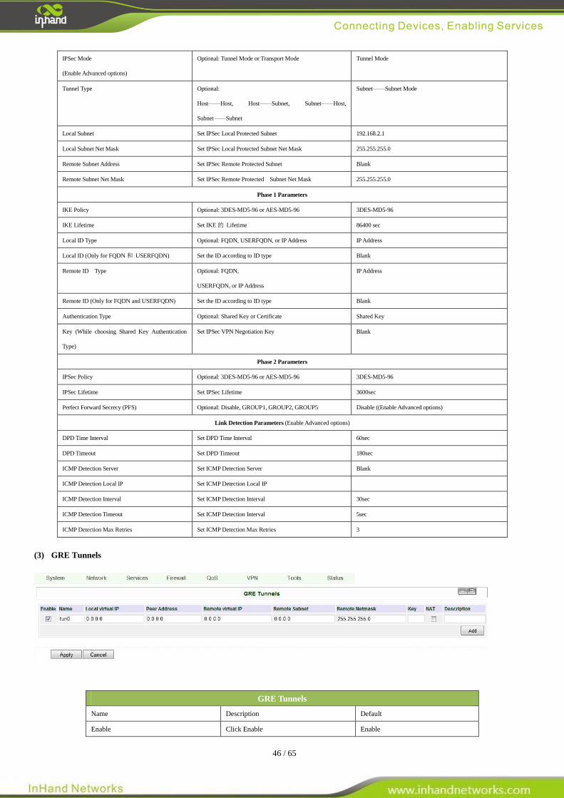
46 / 65
IPSec Mode
(Enable Advanced options)
Optional: Tunnel Mode or Transport Mode Tunnel Mode
Tunnel Type Optional:
Host——Host, Host——Subnet, Subnet——Host,
Subnet——Subnet
Subnet——Subnet Mode
Local Subnet Set IPSec Local Protected Subnet 192.168.2.1
Local Subnet Net Mask Set IPSec Local Protected Subnet Net Mask 255.255.255.0
Remote Subnet Address Set IPSec Remote Protected Subnet Blank
Remote Subnet Net Mask Set IPSec Remote Protected Subnet Net Mask 255.255.255.0
Phase 1 Parameters
IKE Policy Optional: 3DES-MD5-96 or AES-MD5-96 3DES-MD5-96
IKE Lifetime Set IKE 的 Lifetime 86400 sec
Local ID Type Optional: FQDN, USERFQDN, or IP Address IP Address
Local ID (Only for FQDN 和 USERFQDN) Set the ID according to ID type Blank
Remote ID Type Optional: FQDN,
USERFQDN, or IP Address
IP Address
Remote ID (Only for FQDN and USERFQDN) Set the ID according to ID type Blank
Authentication Type Optional: Shared Key or Certificate Shared Key
Key (While choosing Shared Key Authentication
Type)
Set IPSec VPN Negotiation Key Blank
Phase 2 Parameters
IPSec Policy Optional: 3DES-MD5-96 or AES-MD5-96 3DES-MD5-96
IPSec Lifetime Set IPSec Lifetime 3600sec
Perfect Forward Secrecy (PFS) Optional: Disable, GROUP1, GROUP2, GROUP5 Disable ((Enable Advanced options)
Link Detection Parameters (Enable Advanced options)
DPD Time Interval Set DPD Time Interval 60sec
DPD Timeout Set DPD Timeout 180sec
ICMP Detection Server Set ICMP Detection Server Blank
ICMP Detection Local IP Set ICMP Detection Local IP
ICMP Detection Interval Set ICMP Detection Interval 30sec
ICMP Detection Timeout Set ICMP Detection Interval 5sec
ICMP Detection Max Retries Set ICMP Detection Max Retries 3
(3) GRE Tunnels
GRE Tunnels
Name Description Default
Enable Click Enable Enable
47 / 65
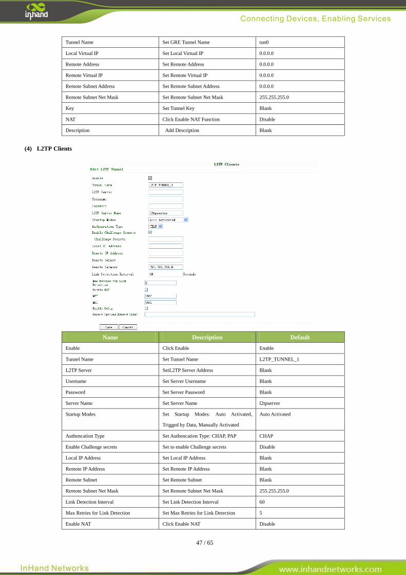
Tunnel Name Set GRE Tunnel Name tun0
Local Virtual IP Set Local Virtual IP 0.0.0.0
Remote Address Set Remote Address 0.0.0.0
Remote Virtual IP Set Remote Virtual IP 0.0.0.0
Remote Subnet Address Set Remote Subnet Address 0.0.0.0
Remote Subnet Net Mask Set Remote Subnet Net Mask 255.255.255.0
Key Set Tunnel Key Blank
NAT Click Enable NAT Function Disable
Description Add Description Blank
(4) L2TP Clients
Name Description Default
Enable Click Enable Enable
Tunnel Name Set Tunnel Name L2TP_TUNNEL_1
L2TP Server SetL2TP Server Address Blank
Username Set Server Username Blank
Password Set Server Password Blank
Server Name Set Server Name l2tpserver
Startup Modes Set Startup Modes: Auto Activated,
Trigged by Data, Manually Activated
Auto Activated
Authencation Type Set Authencation Type: CHAP, PAP CHAP
Enable Challenge secrets Set to enable Challenge secrets Disable
Local IP Address Set Local IP Address Blank
Remote IP Address Set Remote IP Address Blank
Remote Subnet Set Remote Subnet Blank
Remote Subnet Net Mask Set Remote Subnet Net Mask 255.255.255.0
Link Detection Interval Set Link Detection Interval 60
Max Retries for Link Detection Set Max Retries for Link Detection 5
Enable NAT Click Enable NAT Disable
48 / 65
MTU Set MTU parameters 1500
MRU Set MRU parameters 1500
Enable Debug Mode Click Enable Debug Mode Disable
Expert Options Set Expert Options Blank
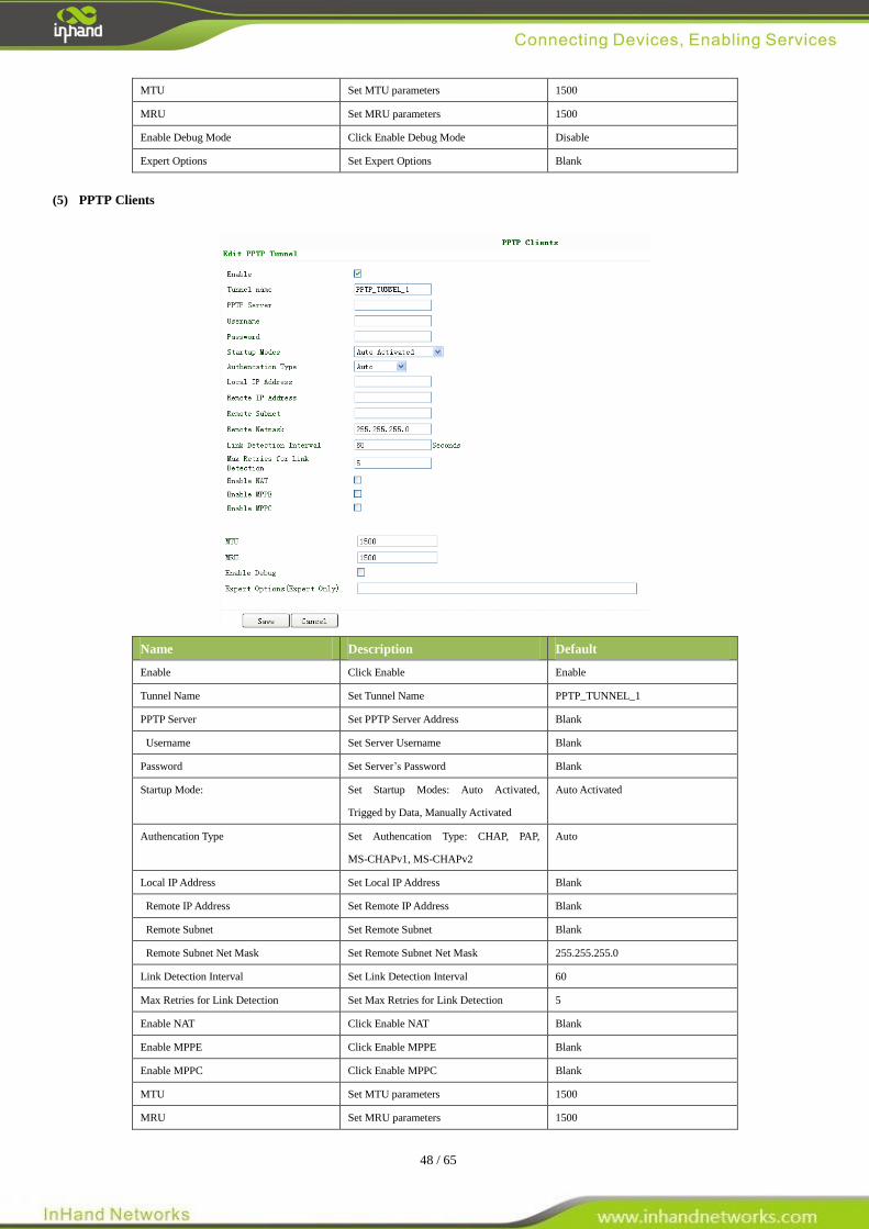
(5) PPTP Clients
Name Description Default
Enable Click Enable Enable
Tunnel Name Set Tunnel Name PPTP_TUNNEL_1
PPTP Server Set PPTP Server Address Blank
Username Set Server Username Blank
Password Set Server’s Password Blank
Startup Mode: Set Startup Modes: Auto Activated,
Trigged by Data, Manually Activated
Auto Activated
Authencation Type Set Authencation Type: CHAP, PAP,
MS-CHAPv1, MS-CHAPv2
Auto
Local IP Address Set Local IP Address Blank
Remote IP Address Set Remote IP Address Blank
Remote Subnet Set Remote Subnet Blank
Remote Subnet Net Mask Set Remote Subnet Net Mask 255.255.255.0
Link Detection Interval Set Link Detection Interval 60
Max Retries for Link Detection Set Max Retries for Link Detection 5
Enable NAT Click Enable NAT Blank
Enable MPPE Click Enable MPPE Blank
Enable MPPC Click Enable MPPC Blank
MTU Set MTU parameters 1500
MRU Set MRU parameters 1500
49 / 65
Enable Debug Mode Click Enable Debug Mode Blank
Expert Options For InHand R&D only Blank
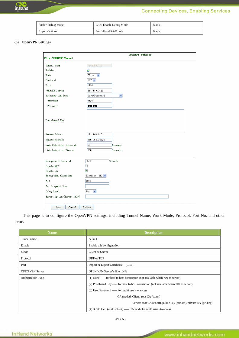
(6) OpenVPN Settings
This page is to configure the OpenVPN settings, including Tunnel Name, Work Mode, Protocol, Port No. and other
items.
Name Description
Tunnel name default
Enable Enable this configuration
Mode Client or Server
Protocol UDP or TCP
Port Import or Export Certificate (CRL)
OPEN VPN Server OPEN VPN Server’s IP or DNS
Authencation Type (1) None ----- for host to host connection (not available when 700 as server)
(2) Pre-shared Key ----- for host to host connection (not available when 700 as server)
(3) User/Password ----- For multi users to access
CA needed: Client: root CA (ca.crt)
Server: root CA (ca.crt), public key (pub.crt), private key (pri.key)
(4) X.509 Cert (multi-client) ----- CA mode for multi users to access
50 / 65
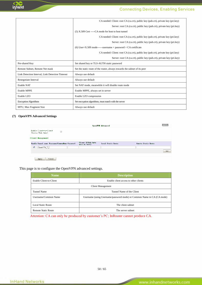
(7) OpenVPN Advanced Settings
This page is to configure the OpenVPN advanced settings.
Name Description
Enable Client-to-Client Enable client access to other clients
Client Management
Tunnel Name Tunnel Name of the Client
Username/Common Name Username (using Username/password mode) or Common Name in CA (CA mode)
Local Static Route The client subnet
Remote Static Route The server subnet
Attention: CA can only be produced by customer’s PC; InRouter cannot produce CA.
CA needed: Client: root CA (ca.crt), public key (pub.crt), private key (pri.key)
Server: root CA (ca.crt), public key (pub.crt), private key (pri.key)
(5) X.509 Cert -----CA mode for host to host tunnel
CA needed: Client: root CA (ca.crt), public key (pub.crt), private key (pri.key)
Server: root CA (ca.crt), public key (pub.crt), private key (pri.key)
(6) User+X.509 mode------username + password + CA certificate
CA needed: Client: root CA (ca.crt), public key (pub.crt), private key (pri.key)
Server: root CA (ca.crt), public key (pub.crt), private key (pri.key)
Pre-shared Key Set shared key or TLS-AUTH static password
Remote Subnet, Remote Net mask Set the static route of the router, always towards the subnet of its peer
Link Detection Interval, Link Detection Timeout Always use default
Renegotiate Interval Always use default
Enable NAT Set NAT mode, meanwhile it will disable route mode
Enable MPPE Enable MPPE, always set in server
Enable LZO Enable LZO compression
Encryption Algorithms Set encryption algorithms, must match with the server
MTU, Max Fragment Size Always use default
51 / 65
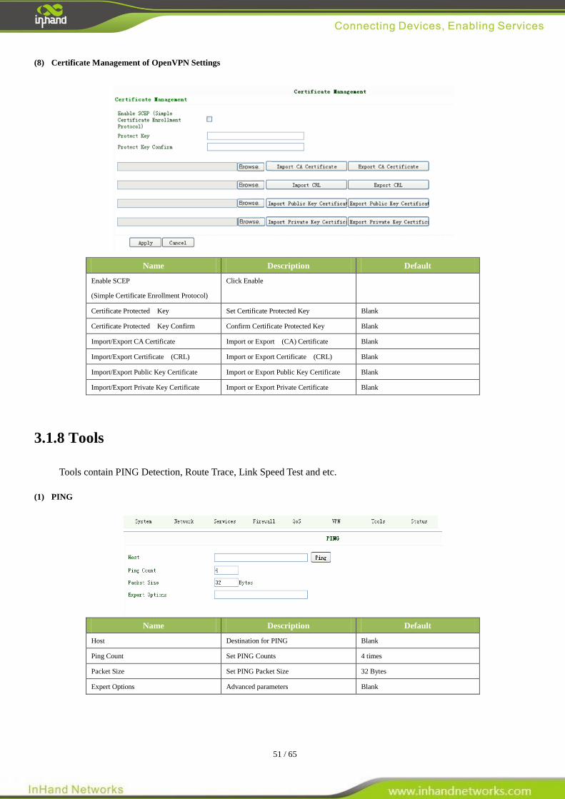
(8) Certificate Management of OpenVPN Settings
Name Description Default
Enable SCEP
(Simple Certificate Enrollment Protocol)
Click Enable
Certificate Protected Key Set Certificate Protected Key Blank
Certificate Protected Key Confirm Confirm Certificate Protected Key Blank
Import/Export CA Certificate Import or Export (CA) Certificate Blank
Import/Export Certificate (CRL) Import or Export Certificate (CRL) Blank
Import/Export Public Key Certificate Import or Export Public Key Certificate Blank
Import/Export Private Key Certificate Import or Export Private Certificate Blank
3.1.8 Tools
Tools contain PING Detection, Route Trace, Link Speed Test and etc.
(1) PING
Name Description Default
Host Destination for PING Blank
Ping Count Set PING Counts 4 times
Packet Size Set PING Packet Size 32 Bytes
Expert Options Advanced parameters Blank
52 / 65
(2) Trace Route
Name Description Default
Host Destination for Trace Route Blank
Max Hops Set Max Hops 20
Time Out Set Time Out 3 sec
Protocol Optional: ICMP/UDP UDP
Expert Options Advanced parameters Blank
(3) Link Speed Test
Test link speed via unload or download
3.1.9 Status
Status contains System, Modem, WLAN, Network Connections, Route Table, Device List and Log.
(1) System Status
This page shows the status of system, including Name, Model Type, Current Version and etc.
53 / 65
(2) Modem Status
This page shows the status of Modem, including signal level.
(3) WLAN (Only STA Series)
This page show joinable access point.
(4) Network Connections
This page shows the network connections via WAN or LAN
54 / 65
(5) Route Table
This page shows the route table of IR6x5.
(6) Device List
This page shows the devices linked with IR6x5.
(7) Log
This page shows the log of system, including download log file.
Under certain situation when there’re problems that can’t be diagnosed at the moment, you’ll be asked to provide the
diagnose log to InHand engineers, you may click “Download System Diagnosing Data” and then send the diagnose log to
us.
.
55 / 65
3.2 CLI Configuration
This chapter will show you how to configure via CLI.
3.2.1 CLI Operation
Step 1: Input telnet LAN IP to login CLI configuration. For example:
Step 2: After connection is succeed, input username and password of IR6x5. The default username/password is
adm/123456
Attention: password will not be showed.
Step 3: Login to User Mode
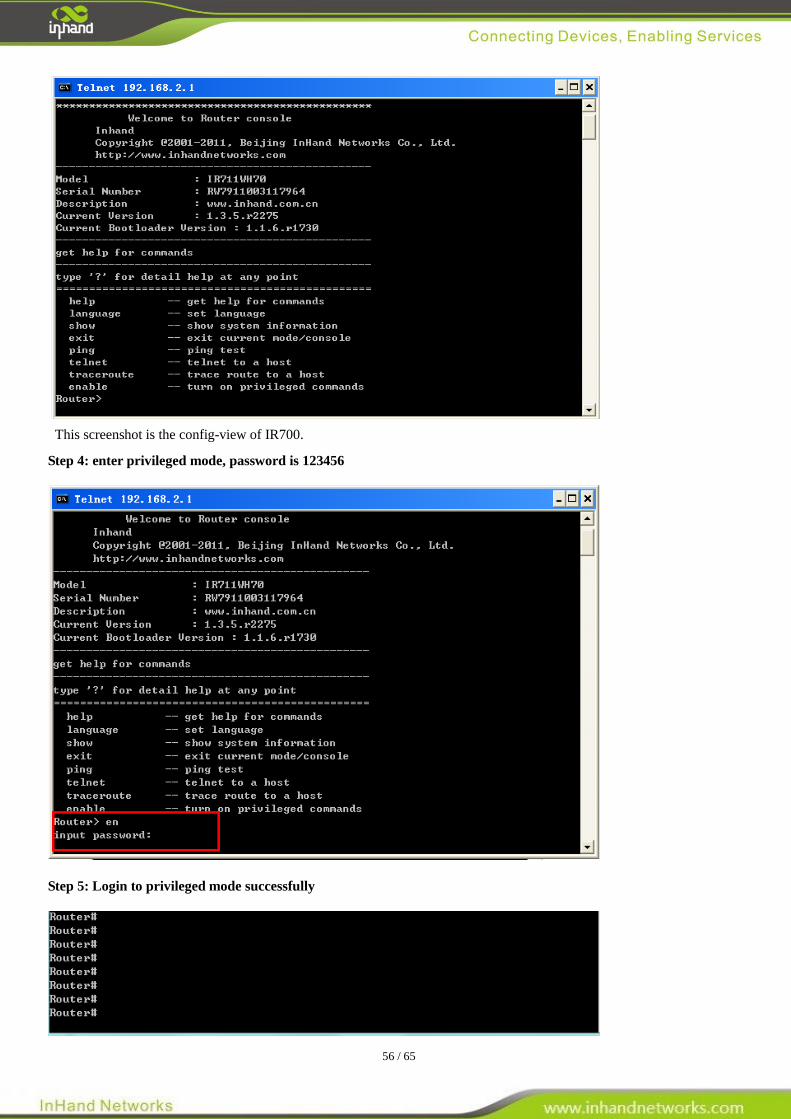
56 / 65
This screenshot is the config-view of IR700.
Step 4: enter privileged mode, password is 123456
Step 5: Login to privileged mode successfully
57 / 65
Step 6: Enter configured mode, then you could configure parameters you want to set up.
3.2.2 CLI command
Configure username and password
Enable serial function
Configure serial port parameters, like baudrate, parity, stop bit and so on.
Enable advanced options of dialup
Configure ICMP server
Configure LAN IP
Enable DHCP function
Configure DHCP IP pool: 192.168.2.10-192.168.2.20
Enable HTTP function
Configure HTTP service port
58 / 65
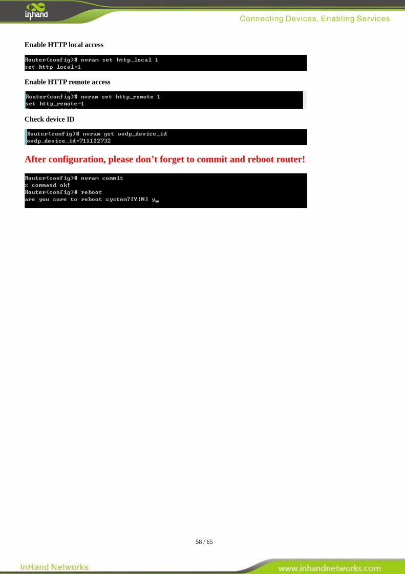
Enable HTTP local access
Enable HTTP remote access
Check device ID
After configuration, please don’t forget to commit and reboot router!
59 / 65
FAQ
1. InRouter is powered on, but can not access Internet through it?
Please check:
Whether the InRouter is inserted with a SIM card.
Whether the SIM card is enabled with data service, whether the service of the SIM card is suspended because of
an overdue charge.
Whether the dialup parameters, e.g. APN, dialup number, account, and password are correctly configured.
Whether the IP Address of your computer is the same subnet with InRouter and the gateway address is InRouter
LAN address.
2. InRouter is powered on, have a ping to detect InRouter from your PC and find packet loss?
Please check if the network crossover cable is in good condition.
3. Forget the setting after revising IP address and can`t configure InRouter?
Method 1: connect InRouter with serial cable, configure it through console port.
Method 2: within 5 seconds after InRouter is powered on, press and hold the Restore button until the ERROR LED
flashes, then release the button and the ERROR LED should goes off, press and hold the button again until
the ERROR LED blinks 6 times, the InRouter is now restored to factory default settings. You may configure
it now.
4. After InRouter is powered on, it frequently auto restarts. Why does this happen?
Please check:
Whether the module works normally.
Whether the InRouter is inserted with a SIM card.
Whether the SIM card is enabled with data service, whether the service of the SIM card is suspended because
of an overdue charge.
Whether the dialup parameters, e.g. APN, dialup number, account, and password are correctly configured.
Whether the signal is normal.
Whether the power supply voltage is normal.
5. Why does upgrading the firmware of my InRouter always fail?
Please check:
When upgrading locally, check if the local PC and InRouter are in the same network segment.
When upgrading remotely, please first make sure the InRouter can access Internet.
6. After InRouter establishes VPN with the VPN server, your PC under InRouter can connect to the server, but the
center can`t connect to your PC under InRouter?
Please make sure the firewall of your computer is disabled.
7. After InRouter establishes VPN with the VPN server, Your PC can`t connect to the server?
Please make sure “Shared Connection” on “Network=>WAN” or “Network=>Dialup” is enabled in the configuration
of InRouter.
8. InRouter is powered on, but the Power LED is not on?
Check if the protective tube is burn out.
Check the power supply voltage range and if the positive and negative electrodes are correctly connected.
60 / 65
9. InRouter is powered on, but the Network LED is not on when connected to PC?
When the PC and InRouter are connected with a network cable, please check whether a network crossover cable
is used.
Check if the network cable is in good condition.
Please set the network card of the PC to 10/100M and full duplex.
10. InRouter is powered on, when connected with PC, the Network LED is normal but can`t have a ping detection
to the InRouter?
Check if the IP Address of the PC and InRouter are in the same subnet and the gateway address is InRouter LAN
address.
11. InRouter is powered on, but can`t configure through the web interface?
Whether the IP Address of your computer is the same subnet with InRouter and the gateway address is InRouter
LAN address.
Check the firewall settings of the PC used to configure InRouter, whether this function is shielded by the firewall.
12. The InRouter dialup always fails, I can`t find out why?
Please restore InRouter to factory default settings and configure the parameters again.
13. How to restore InRouter to factory default settings?
- IR6X5 routers:
1. Press and hold the Restore button, power on InRouter;
2. Release the button until after the STATUS LED flashes and the ERROR LED is on;
3. After the button is released, the ERROR LED will go off, within 30s press and hold the Restore button again until
the ERROR LED flashes;
4. Release the button, the system is now successfully restored to factory default settings.

61 / 65
Support
In case you have problems with the installation and use, please address them to us by e-mail:
InHand Networks
Headquarters US Office
West Wing, 11th Floor, Qi Ming International Mansion 7926 Jones Branch Dr. Suite 110
Wang Jing Science Park, Chao Yang District McLean, Virginia,22102
Beijing, 100102, China USA
T:+86-10-6439-1099 T: +1-703-348-2988
F:+86-10-8417-0089 F:+1-703-348-2988
[email protected] www.inhandnetworks.com