Embed Size (px)
Citation preview

Innovator Gas Manifold Systems

H E A LT H C A R E M A N I F O L D S
• FHM2 Series . . . . . . . . . . . . . . . . . . . . . . . . . . . . . . . . . . . . . . . . . . . . . . . . . . . . . . . . . . . . . . . . . . . . . . . . 4 - 5
• HGM2 Series . . . . . . . . . . . . . . . . . . . . . . . . . . . . . . . . . . . . . . . . . . . . . . . . . . . . . . . . . . . . . . . . . . . . . . . . 6 - 7
• LC Series . . . . . . . . . . . . . . . . . . . . . . . . . . . . . . . . . . . . . . . . . . . . . . . . . . . . . . . . . . . . . . . . . . . . . . . . . . . 8 - 9
• CLA Series . . . . . . . . . . . . . . . . . . . . . . . . . . . . . . . . . . . . . . . . . . . . . . . . . . . . . . . . . . . . . . . . . . . . . . . . . . 10
• Dual Line Regulator Assemblies . . . . . . . . . . . . . . . . . . . . . . . . . . . . . . . . . . . . . . . . . . . . . . . 10
I N D U S T R I A L M A N I F O L D S
• BI Series . . . . . . . . . . . . . . . . . . . . . . . . . . . . . . . . . . . . . . . . . . . . . . . . . . . . . . . . . . . . . . . . . . . . . . . . . . . . 12 - 13
• LC Series . . . . . . . . . . . . . . . . . . . . . . . . . . . . . . . . . . . . . . . . . . . . . . . . . . . . . . . . . . . . . . . . . . . . . . . . . . . 14 - 15
• MS, MD, SD Series . . . . . . . . . . . . . . . . . . . . . . . . . . . . . . . . . . . . . . . . . . . . . . . . . . . . . . . . . . . . . . . . . . . 16 - 17
• Special Configurations . . . . . . . . . . . . . . . . . . . . . . . . . . . . . . . . . . . . . . . . . . . . . . . . . . . . . . . . . . . . . . . . . 18
S P E C I A LT Y GA S M A N I F O L D S
• LAB Series . . . . . . . . . . . . . . . . . . . . . . . . . . . . . . . . . . . . . . . . . . . . . . . . . . . . . . . . . . . . . . . . . . . . . . . . . . 20 - 21
• High Purity Brass Manifolds . . . . . . . . . . . . . . . . . . . . . . . . . . . . . . . . . . . . . . . . . . . . . . . . . . . . . . . . . . . . . 22 - 23
• High Purity Stainless Steel Manifolds . . . . . . . . . . . . . . . . . . . . . . . . . . . . . . . . . . . . . . . . . . . . . . . . . . . . . . 24 - 25
• Purge Assemblies . . . . . . . . . . . . . . . . . . . . . . . . . . . . . . . . . . . . . . . . . . . . . . . . . . . . . . . . . . . . . . . . . . . . . 26
AC C E S S O R I E S
• Cylinder Brackets, Manifold Bracket & Mounting Hardware, Floor Stands . . . . . . . . . . . . . . . . . . . . . . . . . . 28
• Flashback Arrestors, Fuel Gas Safety Kits, Fuel Gas Alarm Kits . . . . . . . . . . . . . . . . . . . . . . . . . . . . . . . . . . 29
• Pressure Switches, Remote Alarm Panels & Power Supplies . . . . . . . . . . . . . . . . . . . . . . . . . . . . . . . . . . . . . 30
• Station Drops, Line Station Regulators, Flowmeters . . . . . . . . . . . . . . . . . . . . . . . . . . . . . . . . . . . . . . . . . . . . 31
• Manifold Regulators, In-Line Regulators . . . . . . . . . . . . . . . . . . . . . . . . . . . . . . . . . . . . . . . . . . . . . . . . . . . . 32
• Packless Diaphragm Valves, Bypass Valve Assembly, Header Valves . . . . . . . . . . . . . . . . . . . . . . . . . . . . . . 33
• Ball Valves, Master Valves, Line Station Valves . . . . . . . . . . . . . . . . . . . . . . . . . . . . . . . . . . . . . . . . . . . . . . . 34
• Union Adaptors, Tailpieces & Nuts, Pipeline Check Valves, Check Valve OutletsRelief Valves . . . . . . . . . . . . . . . . . . . . . . . . . . . . . . . . . . . . . . . . . . . . . . . . . . . . . . . . . . . . . . . . . . . . . . . . . 35
• Gas Heaters, Proportional Gas Mixers . . . . . . . . . . . . . . . . . . . . . . . . . . . . . . . . . . . . . . . . . . . . . . . . . . . . . 36
• NFPA Drawings . . . . . . . . . . . . . . . . . . . . . . . . . . . . . . . . . . . . . . . . . . . . . . . . . . . . . . . . . . . . . . . . . . . . . . 37
• Technical Information . . . . . . . . . . . . . . . . . . . . . . . . . . . . . . . . . . . . . . . . . . . . . . . . . . . . . . . . . . . . . . . . . . 38
T A B L E O F C O N T E N T S

HHHHEEEEAAAALLLLTTTTHHHHCCCC AAAARRRREEEE MMMMAAAANNNNIIIIFFFFOOOOLLLLDDDDSSSS
WESTERN INNOVATOR
HEALTHCARE MANIFOLD SYSTEMS
Western Innovator Healthcare Manifolds offer an extensive range of standard features,
proven performance, outstanding value, and customization to meet special requirements.
Western Innovator Healthcare Manifolds are:
• Specifically designed to meet a wide variety of healthcare applications that require uninterrupted gas service. Systems automatically switch from the primary gas supply to the secondary gas supply.
• Designed and manufactured to meet NFPA-99 1999 safety and performance requirements.
• Cleaned and tested for the indicated gas service. Factory-set functional components are protected inside a tamper-resistant case.
• Easy to install and use.
Specify: Control Type (V) - Service (W) - Number
Example 1: FHM2-9-12VF represents FHM2 with oxygen gas service and a
Example 2: FHM2HP-7-6 represents FHM2HP with nitrogen gas service with a
CONTROL TYPE (V) GAS SERVICE (W) # OFCYL’S (X)
(2) Breathing Air CGA-346(4) Carbon Dioxide CGA-320(5) Helium CGA-580(7) Nitrogen CGA-580(8) Nitrous Oxide CGA-326(9) Oxygen CGA-540
For more information, call Western Customer Service
FHM2 (30 to 70 psig)
FHM2HL (30 to 70 psig)(For CO2 and N2O – includes 500 scfh heater)
FHM2HP (100 to 190 psig)
HOW TO ORDER
F H M 2
FH
M2
s p e c i f i c a t i o n s
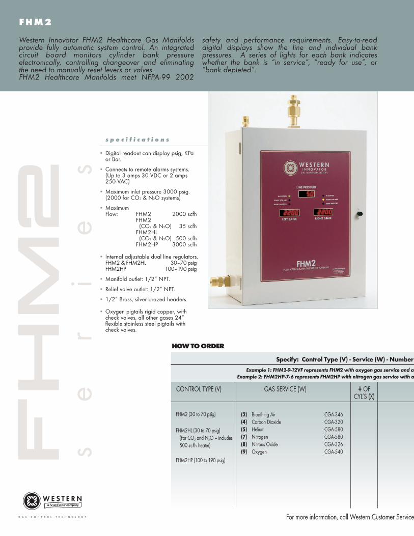
• Digital readout can display psig, KPa or Bar.
• Connects to remote alarms systems.(Up to 3 amps 30 VDC or 2 amps 250 VAC)
• Maximum inlet pressure 3000 psig.(2000 for CO2 & N2O systems)
• Maximum Flow: FHM2 2000 scfh
FHM2 (CO2 & N2O) 35 scfh
FHM2HL(CO2 & N2O) 500 scfh
FHM2HP 3000 scfh
• Internal adjustable dual line regulators.FHM2 & FHM2HL 30–70 psigFHM2HP 100–190 psig
• Manifold outlet: 1/2” NPT.
• Relief valve outlet: 1/2” NPT.
• 1/2” Brass, silver brazed headers.
• Oxygen pigtails rigid copper, with check valves, all other gases 24” flexible stainless steel pigtails with check valves.
Western Innovator FHM2 Healthcare Gas Manifoldsprovide fully automatic system control. An integratedcircuit board monitors cylinder bank pressureelectronically, controlling changeover and eliminatingthe need to manually reset levers or valves.FHM2 Healthcare Manifolds meet NFPA-99 2002
safety and performance requirements. Easy-to-readdigital displays show the line and individual bankpressures. A series of lights for each bank indicateswhether the bank is “in service”, “ready for use”, or“bank depleted”.
s
e
r
i
e
s
of Cylinders (X) Header Configuration (Y) Mounting (Z)
vertical crossover bank of 6 cylinders per side which is mounted on a floor stand.
standard header configuration of 3 cylinders per side which is mounted on the wall.
HEADER MOUNTING (Z)CONFIGURATION (Y)
BLANK = Wall mountF = Floor mounted
at 1-800-783-7890 for technical data sheets
BLANK - Standard 10 inches on center
V - Vertical crossover 10 inches on center
S - Staggered 5 inches on center
C - Crossover 10 inches on center
U-Shaped - Drawing RequiredL-Shaped - Drawing Required
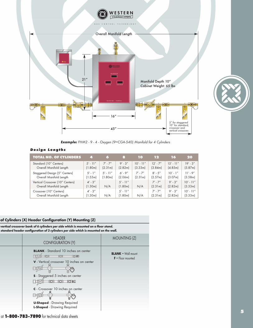
Example: FHM2 - 9 - 4 - Oxygen (9=CGA-540) Manifold for 4 Cylinders
5
Overall Manifold Length
Manifold Depth 10”Cabinet Weight: 65 lbs
21”
16”
45”
TOTAL NO. OF CYLINDERS 4 6 8 10 12 16 20
Standard (10” Centers) 5’ - 11” 7’ - 7” 9’ - 3” 10’ - 11” 12’ - 7” 15’ - 11” 19’ - 3”Overall Manifold Length (1.80m) (2.31m) (2.82m) (3.33m) (3.84m) (4.85m) (5.87m)
Staggered Design (5” Centers) 5’ - 1” 5’ - 11” 6’ - 9” 7’ - 7” 8’ - 5” 10’ - 1” 11’ - 9”Overall Manifold Length (1.55m) (1.80m) (2.06m) (2.31m) (2.57m) (3.07m) (3.58m)
Vertical Crossover (10” Centers) 4’ - 3” 5’ - 11” 7’ - 7” 9’ - 3” 10’ - 11”Overall Manifold Length (1.30m) N/A (1.80m) N/A (2.31m) (2.82m) (3.33m)
Crossover (10” Centers) 4’ - 3” 5’ - 11” 7’ - 7” 9’ - 3” 10’ - 11”Overall Manifold Length (1.30m) N/A (1.80m) N/A (2.31m) (2.82m) (3.33m)
D e s i g n L e n g t h s
5” for staggered10” for standard,crossover and vertical crossover.
Specify: Control Type (V) - Service (W) - Number
Example 1: HGM2-9-12VF represents HGM2 with oxygen gas service and a
Example 2: HGM2HP-7-6 represents HGM2HP with nitrogen gas service with a
CONTROL TYPE (V) GAS SERVICE (W) # OFCYL’S (X)
(2) Breathing Air CGA-346(4) Carbon Dioxide CGA-320(5) Helium CGA-580(7) Nitrogen CGA-580(8) Nitrous Oxide CGA-326(9) Oxygen CGA-540
For more information, call Western Customer Service
HGM2 (30 to 55 psig)
HGM2HL (30 to 55 psig)(For CO2 and N2O – includes 500 scfh heater)
HGM2HP (50 to 200 psig)
HOW TO ORDER
H G M 2
HG
M2
s p e c i f i c a t i o n s
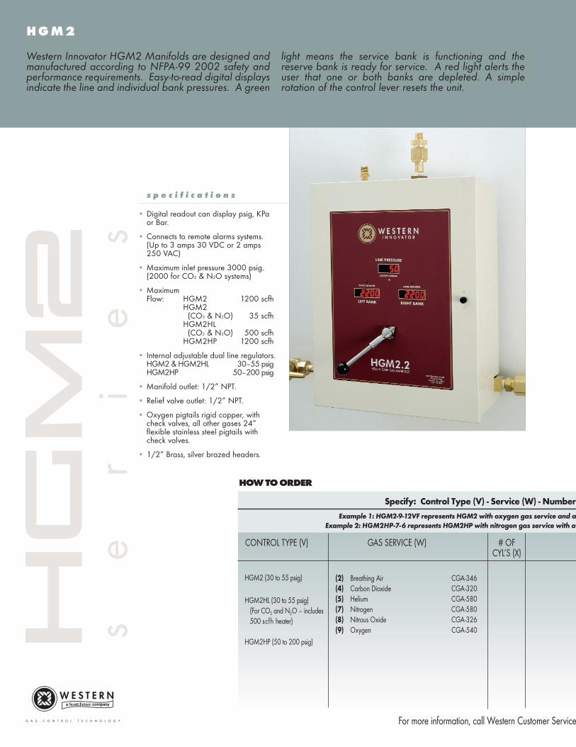
• Digital readout can display psig, KPa or Bar.
• Connects to remote alarms systems.(Up to 3 amps 30 VDC or 2 amps 250 VAC)
• Maximum inlet pressure 3000 psig.(2000 for CO2 & N2O systems)
• Maximum Flow: HGM2 1200 scfh
HGM2 (CO2 & N2O) 35 scfh
HGM2HL(CO2 & N2O) 500 scfh
HGM2HP 1200 scfh
• Internal adjustable dual line regulators.HGM2 & HGM2HL 30–55 psigHGM2HP 50–200 psig
• Manifold outlet: 1/2” NPT.
• Relief valve outlet: 1/2” NPT.
• Oxygen pigtails rigid copper, with check valves, all other gases 24” flexible stainless steel pigtails with check valves.
• 1/2” Brass, silver brazed headers.
Western Innovator HGM2 Manifolds are designed andmanufactured according to NFPA-99 2002 safety andperformance requirements. Easy-to-read digital displaysindicate the line and individual bank pressures. A green
light means the service bank is functioning and thereserve bank is ready for service. A red light alerts theuser that one or both banks are depleted. A simplerotation of the control lever resets the unit.
s
e
r
i
e
s

of Cylinders (X) Header Configuration (Y) Mounting (Z)
vertical crossover bank of 6 cylinders per side which is mounted on a floor stand.
standard header configuration of 3 cylinders per side which is mounted on the wall.
HEADER MOUNTING (Z)CONFIGURATION (Y)
BLANK = Wall mountF = Floor mounted
at 1-800-783-7890 for technical data sheets
BLANK - Standard 10 inches on center
V - Vertical crossover 10 inches on center
S - Staggered 5 inches on center
C - Crossover 10 inches on center
U-Shaped - Drawing RequiredL-Shaped - Drawing Required
Example: HGM2 - 9 - 4 - Oxygen (9=CGA-540) Manifold for 4 Cylinders
7
Overall Manifold Length
Manifold Depth 10”Cabinet Weight: 65 lbs
21”
16”
45”
TOTAL NO. OF CYLINDERS 4 6 8 10 12 16 20
Standard (10” Centers) 5’ - 11” 7’ - 7” 9’ - 3” 10’ - 11” 12’ - 7” 15’ - 11” 19’ - 3”Overall Manifold Length (1.80m) (2.31m) (2.82m) (3.33m) (3.84m) (4.85m) (5.87m)
Staggered Design (5” Centers) 5’ - 1” 5’ - 11” 6’ - 9” 7’ - 7” 8’ - 5” 10’ - 1” 11’ - 9”Overall Manifold Length (1.55m) (1.80m) (2.06m) (2.31m) (2.57m) (3.07m) (3.58m)
Vertical Crossover (10” Centers) 4’ - 3” 5’ - 11” 7’ - 7” 9’ - 3” 10’ - 11”Overall Manifold Length (1.30m) N/A (1.80m) N/A (2.31m) (2.82m) (3.33m)
Crossover (10” Centers) 4’ - 3” 5’ - 11” 7’ - 7” 9’ - 3” 10’ - 11”Overall Manifold Length (1.30m) N/A (1.80m) N/A (2.31m) (2.82m) (3.33m)
D e s i g n L e n g t h s
5” for staggered10” for standard,crossover and vertical crossover.
Specify: Control Type (V) - Service (W)
Example: LC - 3 - 4 represents LC with Argon gas service for
CONTROL TYPE (V) GAS SERVICE (W) # OFCYL’S (X)
(3) Argon CGA-580(4) Carbon Dioxide CGA-320(5) Helium CGA-580(7) Nitrogen CGA-580(8) Nitrous Oxide CGA-326(9) Oxygen CGA-540
For more information, call Western Customer Service
LC (40 - 85 psig)
LCHP (40 - 180 psig)(Nitrogen units only are adjustable - 40 - 210 psig)
HOW TO ORDER
L C
LC
s p e c i f i c a t i o n s
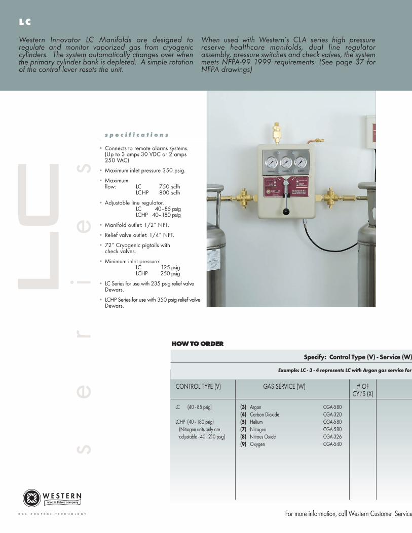
• Connects to remote alarms systems.(Up to 3 amps 30 VDC or 2 amps 250 VAC)
• Maximum inlet pressure 350 psig.
• Maximum flow: LC 750 scfh
LCHP 800 scfh
• Adjustable line regulator.LC 40–85 psigLCHP 40–180 psig
• Manifold outlet: 1/2” NPT.
• Relief valve outlet: 1/4” NPT.
• 72” Cryogenic pigtails with check valves.
• Minimum inlet pressure: LC 125 psigLCHP 250 psig
• LC Series for use with 235 psig relief valveDewars.
• LCHP Series for use with 350 psig relief valveDewars.
Western Innovator LC Manifolds are designed toregulate and monitor vaporized gas from cryogeniccylinders. The system automatically changes over whenthe primary cylinder bank is depleted. A simple rotationof the control lever resets the unit.
When used with Western’s CLA series high pressurereserve healthcare manifolds, dual line regulatorassembly, pressure switches and check valves, the systemmeets NFPA-99 1999 requirements. (See page 37 forNFPA drawings)
s
e
r
i
e
s
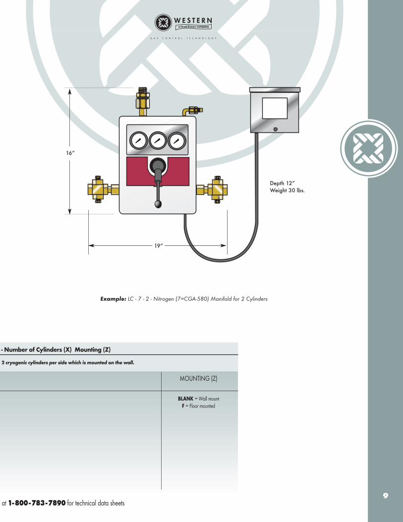
- Number of Cylinders (X) Mounting (Z)
2 cryogenic cylinders per side which is mounted on the wall.
MOUNTING (Z)
BLANK = Wall mountF = Floor mounted
at 1-800-783-7890 for technical data sheets
Example: LC - 7 - 2 - Nitrogen (7=CGA-580) Manifold for 2 Cylinders
9
Depth 12”Weight 30 lbs.
19”
16”
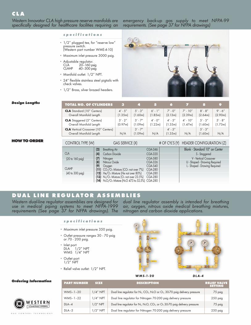
C L AWestern Innovator CLA high pressure reserve manifolds arespecifically designed for healthcare facilities requiring an
emergency back-up gas supply to meet NFPA-99requirements. (See page 37 for NFPA drawings)
D U A L L I N E R E G U L AT O R A S S E M B L I E SWestern dual-line regulator assemblies are designed foruse in medical piping systems to meet NFPA-1999requirements (See page 37 for NFPA drawings). The
dual line regulator assembly is intended for breathingair, oxygen, nitrous oxide medical breathing mixtures,nitrogen and carbon dioxide applications.
s p e c i f i c a t i o n s
• Maximum inlet pressure 350 psig.
• Outlet pressure ranges 30 - 70 psigor 70 - 200 psig.
• Inlet portDLA 1/2” NPTWMS 1/4” NPT
• Outlet port1/2” NPT
• Relief valve outlet: 1/2” NPT.
TOTAL NO. OF CYLINDERS 3 4 5 6 7 8 9
CLA Standard (10” Centers) 4’ - 5” 5’ - 3” 6’ - 1” 7’ - 0” 7’ - 10” 8’ - 8” 9’ - 6”Overall Manifold Length (1.35m) (1.60m) (1.85m) (2.13m) (2.39m) (2.64m) (2.90m)
CLA Staggered (5” Centers) 3’ - 2” 3’ - 7” 4’ - 0” 4’ - 5” 4’ - 10” 5’ - 3” 5’ - 8”Overall Manifold Length (0.97m) (1.09m) (1.22m) (1.35m) (1.47m) (1.60m) (1.73m)
CLA Vertical Crossover (10” Centers) 3’ - 7” 4’ - 5” 5’ - 3”Overall Manifold Length N/A (1.09m) N/A (1.35m) N/A (1.60m) N/A
Design Lengths
s p e c i f i c a t i o n s
• 1/2” plugged tee, for “reserve low” pressure switch.(Western part number WME-4-10)
• Maximum inlet pressure 3000 psig.
• Adjustable regulator.CLA 20–160 psigCLAHP 40–300 psig
• Manifold outlet: 1/2” NPT.
• 24” flexible stainless steel pigtails with check valves.
• 1/2” Brass, silver brazed headers.
PART NUMBER SIZE DESCRIPTION RELIEF VALVESETTING
WMS–1–20 1/4” NPT Dual line regulator for N2, CO2, N2O or O2, 30-70 psig delivery pressure 75 psig
WMS–1–22 1/4” NPT Dual line regulator for Nitrogen 70-200 psig delivery pressure 250 psig
DLA–4 1/2” NPT Dual line regulator for N2, N2O, CO2, or O2, 30-70 psig delivery pressure 75 psig
DLA–5 1/2” NPT Dual line regulator for Nitrogen 70-200 psig delivery pressure 250 psig
Ordering Information
CONTROL TYPE (W) GAS SERVICE (X) # OF CYL’S (Y) HEADER CONFIGURATION (Z)(2) Breathing Air CGA-346 Blank - Standard 10” on Center(4) Carbon Dioxide CGA-320 S - Staggered(7) Nitrogen CGA-580 V - Vertical Crossover(8) Nitrous Oxide CGA-326 U - Shaped - Drawing Required(9) Oxygen CGA-540 L - Shaped - Drawing Required(11) CO2/O2 Mixture (CO2 not over 7%) CGA-280(12) He/O2 Mixture (He not over 80%) CGA-280(13) N2/O2 Mixture (O2 not over 23.5%) CGA-280(14) N2O/O2 Mixture (N2O 47.5 to 52.5%) CGA-280
HOW TO ORDER
CLA
(20 to 160 psig)
CLAHP (40 to 300 psig)
WMS-1-20 DL A -4
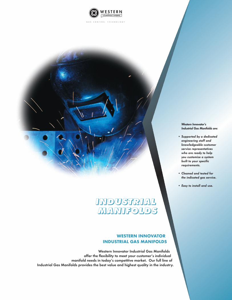
IIIINNNNDDDDUUUUSSSSTTTTRRRRIIIIAAAALLLL MMMMAAAANNNNIIIIFFFFOOOOLLLLDDDDSSSS
WESTERN INNOVATOR
INDUSTRIAL GAS MANIFOLDS
Western Innovator Industrial Gas Manifolds offer the flexibility to meet your customer’s individual
manifold needs in today’s competitive market. Our full line of Industrial Gas Manifolds provides the best value and highest quality in the industry.
Western Innovator’sIndustrial Gas Manifolds are:
• Supported by a dedicatedengineering staff and knowledgeable customer service representatives who are ready to help you customize a system built to your specific requirements.
• Cleaned and tested for the indicated gas service.
• Easy to install and use.
Specify: Control Type (V) - Service (W) - Number
CONTROL TYPE (V) GAS SERVICE (W) # OFCYL’S (X)
(1) Acetylene (POL) CGA-510(1A) Acetylene (Commercial) CGA-300(2) Compressed Air CGA-346(3) Argon CGA-580(4) Carbon Dioxide CGA-320(5) Helium CGA-580(6) Hydrogen CGA-350(6A) Argon/Methane Mixtures CGA-350(7) Nitrogen CGA-580(7A) Industrial Air/Nitrogen OP CGA-590(8) Nitrous Oxide CGA-326(9) Oxygen CGA-540(10) Liquefied Fuel Gases (LPG) CGA-510
For more information, call Western Customer Service
BI (30 to125 psig)Acetylene (0-15 psig)LPG (0-30 psig)
BIHL (30 to125 psig)(500 SCFH heater included in HL model for CO2 and N2O)
BIHP (50 to 200 psig)(Higher delivery pressure -to 235 psig available upon request)
HOW TO ORDER
B I
BI
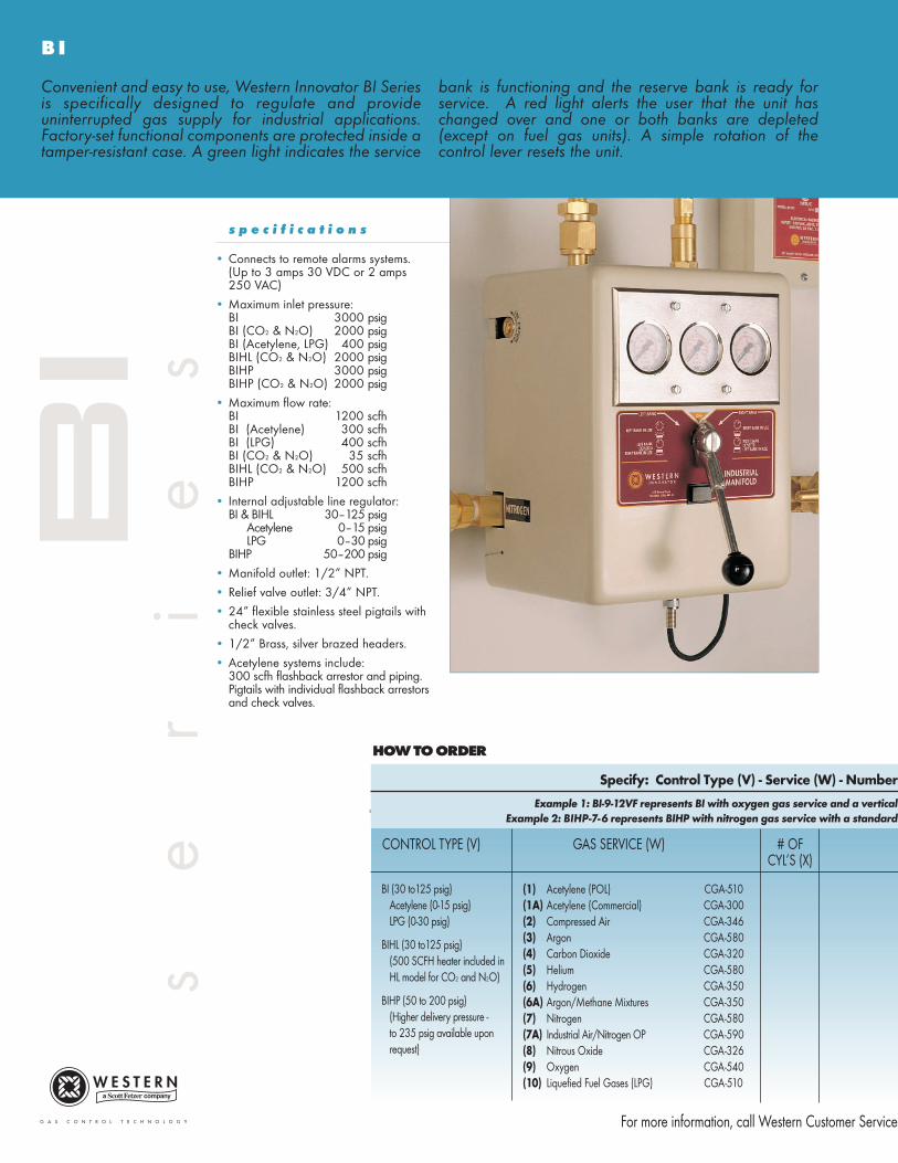
s p e c i f i c a t i o n s
• Connects to remote alarms systems.(Up to 3 amps 30 VDC or 2 amps 250 VAC)
• Maximum inlet pressure:BI 3000 psigBI (CO2 & N2O) 2000 psigBI (Acetylene, LPG) 400 psigBIHL (CO2 & N2O) 2000 psigBIHP 3000 psigBIHP (CO2 & N2O) 2000 psig
• Maximum flow rate:BI 1200 scfhBI (Acetylene) 300 scfhBI (LPG) 400 scfhBI (CO2 & N2O) 35 scfhBIHL (CO2 & N2O) 500 scfhBIHP 1200 scfh
• Internal adjustable line regulator:BI & BIHL 30–125 psig
Acetylene 0–15 psigLPG 0–30 psig
BIHP 50–200 psig
• Manifold outlet: 1/2” NPT.
• Relief valve outlet: 3/4” NPT.
• 24” flexible stainless steel pigtails with check valves.
• 1/2” Brass, silver brazed headers.
• Acetylene systems include:300 scfh flashback arrestor and piping.Pigtails with individual flashback arrestors and check valves.
Convenient and easy to use, Western Innovator BI Seriesis specifically designed to regulate and provideuninterrupted gas supply for industrial applications.Factory-set functional components are protected inside atamper-resistant case. A green light indicates the service
bank is functioning and the reserve bank is ready forservice. A red light alerts the user that the unit haschanged over and one or both banks are depleted(except on fuel gas units). A simple rotation of thecontrol lever resets the unit.
s
e
r
i
e
s
Example 1: BI-9-12VF represents BI with oxygen gas service and a vertical
Example 2: BIHP-7-6 represents BIHP with nitrogen gas service with a standard
of Cylinders (X) Header Configuration (Y) Mounting (Z)
HEADER MOUNTING (Z)CONFIGURATION (Y)
BLANK = Wall mountF = Floor mounted
at 1-800-783-7890 for technical data sheets
BLANK - Standard 10 inches on center13 inches on center for Acetylene & LPG
V - Vertical crossoverStandard 10 inches on center
13 inches on center for Acetylene & LPG
S - Staggered 5 inches on center6.5 inches on center for Acetylene & LPG
C - Crossover (Floor Mount Only)Standard 10 inches on Center13 inches on center for Acetylene & LPG
U-Shaped - Drawing RequiredL-Shaped - Drawing Required
13
TOTAL NO. OF CYLINDERS 2 4 6 8 10 12 16
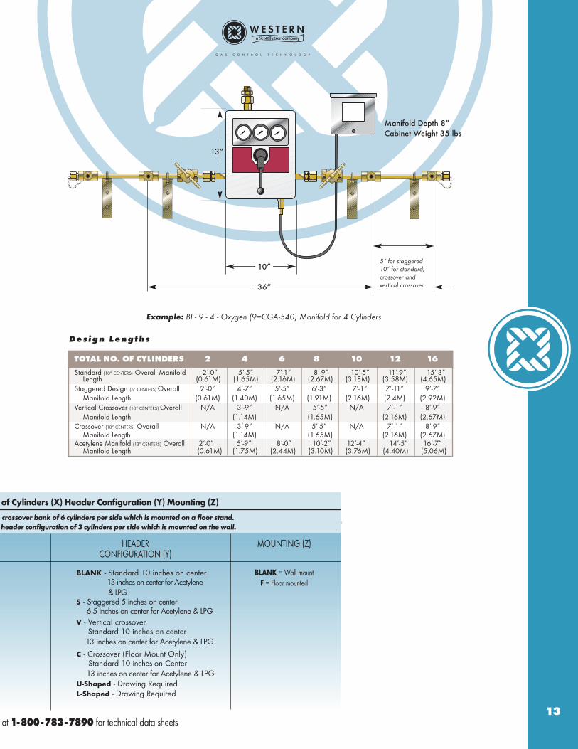
Standard (10” CENTERS) Overall Manifold 2’-0” 5’-5” 7’-1” 8’-9” 10’-5” 11’-9” 15’-3”Length (0.61M) (1.65M) (2.16M) (2.67M) (3.18M) (3.58M) (4.65M)
Staggered Design (5” CENTERS) Overall 2’-0” 4’-7” 5’-5” 6’-3” 7’-1” 7’-11” 9’-7”Manifold Length (0.61M) (1.40M) (1.65M) (1.91M) (2.16M) (2.4M) (2.92M)
Vertical Crossover (10” CENTERS) Overall N/A 3’-9” N/A 5’-5” N/A 7’-1” 8’-9”Manifold Length (1.14M) (1.65M) (2.16M) (2.67M)
Crossover (10” CENTERS) Overall N/A 3’-9” N/A 5’-5” N/A 7’-1” 8’-9”Manifold Length (1.14M) (1.65M) (2.16M) (2.67M)
Acetylene Manifold (13” CENTERS) Overall 2’-0” 5’-9” 8’-0” 10’-2” 12’-4” 14’-5” 16’-7”Manifold Length (0.61M) (1.75M) (2.44M) (3.10M) (3.76M) (4.40M) (5.06M)
D e s i g n L e n g t h s
13”
10”
36”
5” for staggered10” for standard,crossover and vertical crossover.
Manifold Depth 8”Cabinet Weight 35 lbs
Example: BI - 9 - 4 - Oxygen (9=CGA-540) Manifold for 4 Cylinders
crossover bank of 6 cylinders per side which is mounted on a floor stand.
header configuration of 3 cylinders per side which is mounted on the wall.

Specify: Control Type (V) - Service (W)
Example: LC - 3 - 4 represents LC with Argon gas service for
CONTROL TYPE (V) GAS SERVICE (W) # OFCYL’S (X)
(3) Argon CGA-580(4) Carbon Dioxide CGA-320(5) Helium CGA-580(7) Nitrogen CGA-580(8) Nitrous Oxide CGA-326(9) Oxygen CGA-540
For more information, call Western Customer Service
LC (40 - 85 PSIG)
LCHP (40 - 180 PSIG)(Nitrogen units only are adjustable - 40 - 210 PSIG)
HOW TO ORDER
L C
LC
s p e c i f i c a t i o n s
• Connects to remote alarms systems.(Up to 3 amps 30 VDC or 2 amps 250 VAC)
• Maximum inlet pressure 350 psig.
• Maximum flow rate:LC 750 scfhLCHP 800 scfh
• Adjustable line regulator:LC 40–85 psigLCHP 40–180 psig
• Manifold outlet: 1/2” NPT.
• Relief valve outlet: 1/4” NPT.
• 72” Cryogenic pigtails with check valves.
• Minimum inlet: LC 125 psigLCHP 250 psig
• LC Series for use with 235 psig relief valveDewars.
• LCHP Series for use with 350 psig relief valveDewars.
Western Innovator LC Manifolds are designed toregulate and monitor vaporized gas from cryogeniccylinders. Convenient and easy to use, the systemautomatically changes over when the primary cylinderbank is depleted. Simply rotate the control lever to resetthe unit.
A self-contained alarm system alerts the user to thesystem’s current status. A green light indicates theservice bank is functioning and the reserve bank is readyfor service. A red light signals that the system haschanged over and one or both banks are depleted.
s
e
r
i
e
s

- Number of Cylinders (X) Mounting (Z)
2 cryogenic cylinders per side which is mounted on the wall.
MOUNTING (Z)
BLANK = Wall mountF = Floor mounted
at 1-800-783-7890 for technical data sheets15
Example: LC - 7 - 2 - Nitrogen (7=CGA-580) Manifold for 2 Cylinders
Depth 12”Weight 30 lbs.
19”
16”

CONTROL TYPE (V) GAS SERVICE (W) # OFCYL’S (X)
(1) Acetylene (POL) CGA-510(1A) Acetylene (Commercial) CGA-300(2) Compressed Air CGA-346(3) Argon CGA-580(4) Carbon Dioxide CGA-320(5) Helium CGA-580(6) Hydrogen CGA-350(6A) Argon/Methane Mixtures CGA-350(7) Nitrogen CGA-580(7A) Industrial Air/Nitrogen OP CGA-590(8) Nitrous Oxide CGA-326(9) Oxygen CGA-540(10) Liquefied Fuel Gases (LPG) CGA-510
For more information, call Western Customer Service
SDMSMD
Standard delivery pressures forSD, MS & MD units Most gases 20-160 PSIGAcetylene (0-15 PSIG)LPG (0-45 PSIG)
MSHP(only available for non-fuel gas services)Standard delivery pressureAll gases 40-300 PSIG
HOW TO ORDER
M S , M D & S D M a n u a l M a n i f o l d s
MS
, MD
, SD
s p e c i f i c a t i o n s
• Maximum inlet pressure 3000 psig.
• Includes adjustable line regulator.MS, MD & SD 20–160 psigAcetylene 0–15 psigLPG 0–45 psigMSHP, MDHP, SDHP 50–300 psig
• Manifold outlet: 1/2” NPT.
• 24” flexible stainless steel pigtails with check valves.
• 1/2” Brass, silver brazed headers.
• MS & MD Acetylene systems include:300 scfh flashback arrestor andpigtails with individual flashback arrestors and check valves.
Western Innovator’s Manual Gas Manifolds aredesigned to regulate high pressure gas supplies.
Ideal for applications not requiring uninterrupted gasservice.
Note: Different regulators may be substituted to achieve higher delivery pressures on all control types.
s
e
r
i
e
s
MS-9-4
MD-4 -4
SD-7 -2
Specify: Control Type (V) - Service (W) - Number of
Example 1: MD-9-12VF represents MD with oxygen gas service and a vertica
Example 2: MSHP-7-6 represents MSHP with nitrogen gas service with a
Example 1: MD-9-12VF represents MD with oxygen gas service and a vertical
HEADER MOUNTING (Z)CONFIGURATION (Y)
BLANK = Wall mountF = Floor mounted
at 1-800-783-7890 for technical data sheets17
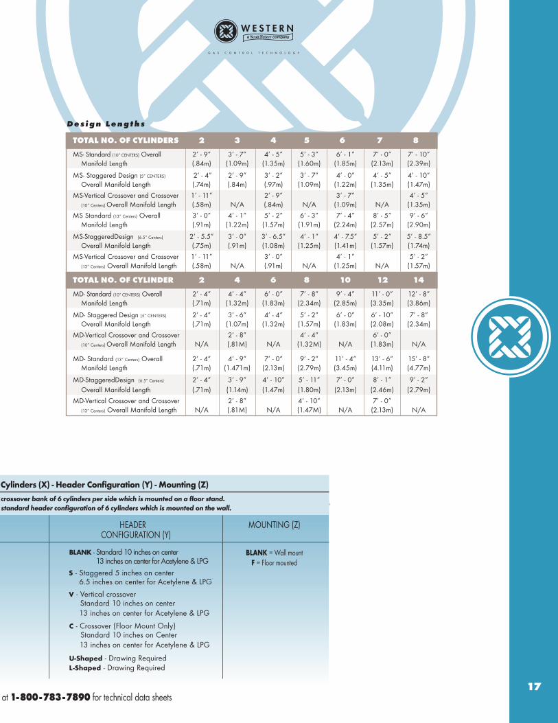
TOTAL NO. OF CYLINDERS 2 3 4 5 6 7 8
MS- Standard (10” CENTERS) Overall 2’ - 9” 3’ - 7” 4’ - 5” 5’ - 3” 6’ - 1” 7’ - 0” 7’ - 10”Manifold Length (.84m) (1.09m) (1.35m) (1.60m) (1.85m) (2.13m) (2.39m)
MS- Staggered Design (5” CENTERS) 2’ - 4” 2’ - 9” 3’ - 2” 3’ - 7” 4’ - 0” 4’ - 5” 4’ - 10”Overall Manifold Length (.74m) (.84m) (.97m) (1.09m) (1.22m) (1.35m) (1.47m)
MS-Vertical Crossover and Crossover 1’ - 11” 2’ - 9” 3’ - 7” 4’ - 5”(10” Centers) Overall Manifold Length (.58m) N/A (.84m) N/A (1.09m) N/A (1.35m)
MS Standard (13” Centers) Overall 3’ - 0” 4’ - 1” 5’ - 2” 6’ - 3” 7’ - 4” 8’ - 5” 9’ - 6”Manifold Length (.91m) (1.22m) (1.57m) (1.91m) (2.24m) (2.57m) (2.90m)
MS-StaggeredDesign (6.5” Centers) 2’ - 5.5” 3’ - 0” 3’ - 6.5” 4’ - 1” 4’ - 7.5” 5’ - 2” 5’ - 8.5”Overall Manifold Length (.75m) (.91m) (1.08m) (1.25m) (1.41m) (1.57m) (1.74m)
MS-Vertical Crossover and Crossover 1’ - 11” 3’ - 0” 4’ - 1” 5’ - 2”(13” Centers) Overall Manifold Length (.58m) N/A (.91m) N/A (1.25m) N/A (1.57m)
D e s i g n L e n g t h s
TOTAL NO. OF CYLINDER 2 4 6 8 10 12 14
MD- Standard (10” CENTERS) Overall 2’ - 4” 4’ - 4” 6’ - 0” 7’ - 8” 9’ - 4” 11’ - 0” 12’ - 8”Manifold Length (.71m) (1.32m) (1.83m) (2.34m) (2.85m) (3.35m) (3.86m)
MD- Staggered Design (5” CENTERS) 2’ - 4” 3’ - 6” 4’ - 4” 5’ - 2” 6’ - 0” 6’ - 10” 7’ - 8”Overall Manifold Length (.71m) (1.07m) (1.32m) (1.57m) (1.83m) (2.08m) (2.34m)
MD-Vertical Crossover and Crossover 2’ - 8” 4’ - 4” 6’ - 0”(10” Centers) Overall Manifold Length N/A (.81M) N/A (1.32M) N/A (1.83m) N/A
MD- Standard (13” Centers) Overall 2’ - 4” 4’ - 9” 7’ - 0” 9’ - 2” 11’ - 4” 13’ - 6” 15’ - 8”Manifold Length (.71m) (1.471m) (2.13m) (2.79m) (3.45m) (4.11m) (4.77m)
MD-StaggeredDesign (6.5” Centers) 2’ - 4” 3’ - 9” 4’ - 10” 5’ - 11” 7’ - 0” 8’ - 1” 9’ - 2” Overall Manifold Length (.71m) (1.14m) (1.47m) (1.80m) (2.13m) (2.46m) (2.79m)
MD-Vertical Crossover and Crossover 2’ - 8” 4’ - 10” 7’ - 0”(13” Centers) Overall Manifold Length N/A (.81M) N/A (1.47M) N/A (2.13m) N/A
BLANK - Standard 10 inches on center13 inches on center for Acetylene & LPG
V - Vertical crossoverStandard 10 inches on center13 inches on center for Acetylene & LPG
S - Staggered 5 inches on center6.5 inches on center for Acetylene & LPG
C - Crossover (Floor Mount Only)Standard 10 inches on Center13 inches on center for Acetylene & LPG
U-Shaped - Drawing RequiredL-Shaped - Drawing Required
Cylinders (X) - Header Configuration (Y) - Mounting (Z)
al crossover bank of 6 cylinders per side which is mounted on a floor stand.
standard header configuration of 6 cylinders which is mounted on the wall.
crossover bank of 6 cylinders per side which is mounted on a floor stand.
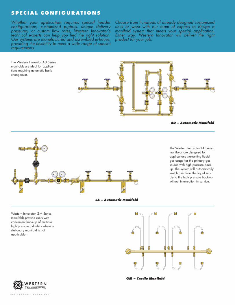
S P E C I A L C O N F I G U R A T I O N S
Whether your application requires special headerconfigurations, customized pigtails, unique deliverypressures, or custom flow rates, Western Innovator’stechnical experts can help you find the right solution.Our systems are manufactured and assembled in-house,providing the flexibility to meet a wide range of specialrequirements.
Choose from hundreds of already designed customizedunits or work with our team of experts to design amanifold system that meets your special application.Either way, Western Innovator will deliver the rightproduct for your job.
AD – Automatic Manifold
LA – Automatic Manifold
GM – Cradle Manifold
The Western Innovator AD Seriesmanifolds are ideal for applica-tions requiring automatic bankchangeover.
The Western Innovator LA Seriesmanifolds are designed forapplications warranting liquidgas usage for the primary gassource with high pressure back-up. The system will automaticallyswitch over from the liquid sup-ply to the high pressure back-upwithout interruption in service.
Western Innovator GM Series manifolds provide users withconvenient hook-up of multiplehigh pressure cylinders where astationary manifold is not applicable.
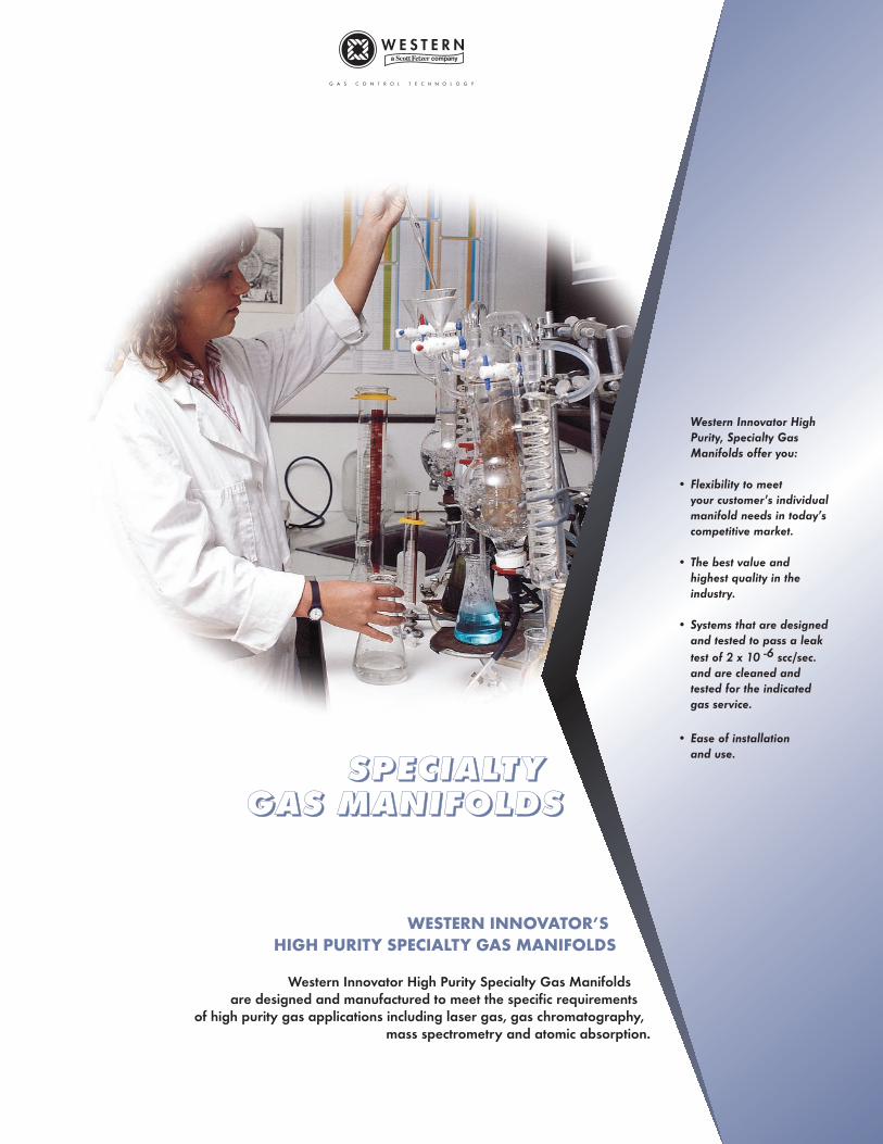
SSSSPPPPEEEECCCCIIIIAAAALLLLTTTT YYYYGGGGAAAASSSS MMMMAAAANNNNIIIIFFFFOOOOLLLLDDDDSSSS
WESTERN INNOVATOR’S
HIGH PURITY SPECIALTY GAS MANIFOLDS
Western Innovator High Purity Specialty Gas Manifolds are designed and manufactured to meet the specific requirements
of high purity gas applications including laser gas, gas chromatography, mass spectrometry and atomic absorption.
Western Innovator High Purity, Specialty Gas Manifolds offer you:
• Flexibility to meet your customer’s individualmanifold needs in today’s competitive market.
• The best value and highest quality in the industry.
• Systems that are designedand tested to pass a leak test of 2 x 10 -6 scc/sec.and are cleaned and tested for the indicated gas service.
• Ease of installation and use.
Specify: Control Type (V)
CONTROL TYPE (V) GAS SERVICE (W)
(1) Acetylene (POL) CGA-510(1A) Acetylene (Commercial) CGA-300(2) Zero Air CGA-346(2A) Zero Air CGA-590(3) Argon CGA-580(4) Carbon Dioxide CGA-320(5) Helium CGA-580(6) Hydrogen CGA-350(7) Nitrogen CGA-580(8) Nitrous Oxide CGA-326(9) Oxygen CGA-540
For more information, call Western Customer Service
LAB1 (30 - 100 psig)Acetylene (0 - 15 psig)
LAB1HP (50 - 200 psig)
HOW TO ORDER
L A B
LA
B
s p e c i f i c a t i o n s
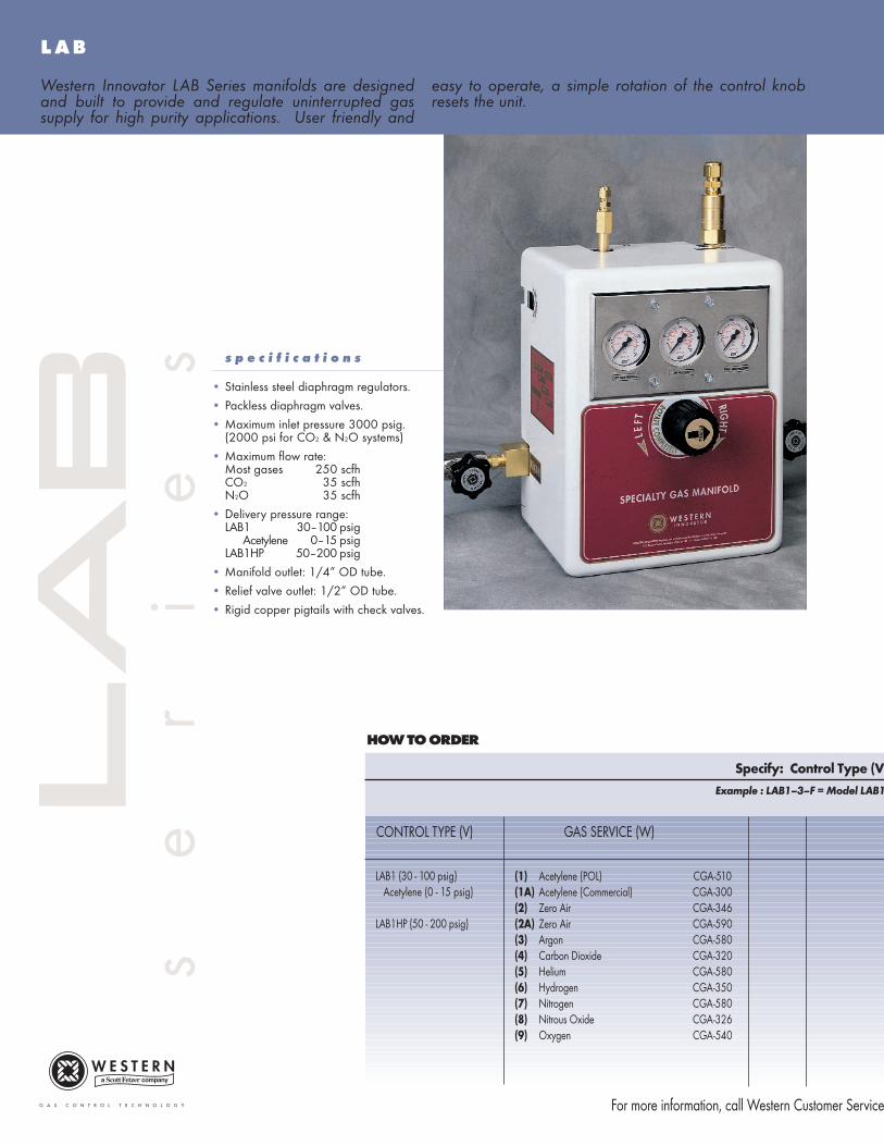
• Stainless steel diaphragm regulators.
• Packless diaphragm valves.
• Maximum inlet pressure 3000 psig.(2000 psi for CO2 & N2O systems)
• Maximum flow rate:Most gases 250 scfhCO2 35 scfhN2O 35 scfh
• Delivery pressure range:LAB1 30–100 psig
Acetylene 0–15 psigLAB1HP 50–200 psig
• Manifold outlet: 1/4” OD tube.
• Relief valve outlet: 1/2” OD tube.
• Rigid copper pigtails with check valves.
Western Innovator LAB Series manifolds are designedand built to provide and regulate uninterrupted gassupply for high purity applications. User friendly and
easy to operate, a simple rotation of the control knobresets the unit.
s
e
r
i
e
s
Example : LAB1–3–F = Model LAB1,
) - Service (W) - Mounting (Z)
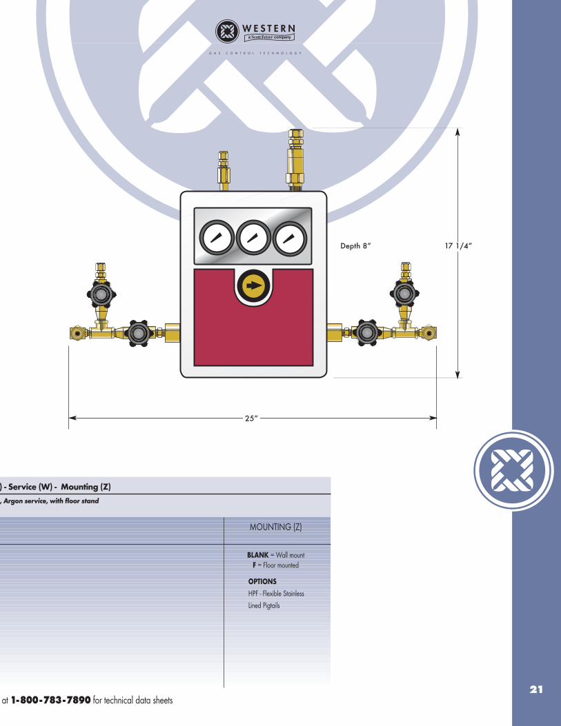
MOUNTING (Z)
BLANK = Wall mountF = Floor mounted
at 1-800-783-7890 for technical data sheets21
25”
17 1/4”Depth 8”
OPTIONS
HPF - Flexible Stainless
Lined Pigtails
, Argon service, with floor stand
Specify: Control Type (V) - Service (W) - Number
Example : HBAC2–5–6 = Model HBAC2, Helium service
CONTROL TYPE (V) GAS SERVICE (W) # OF CYL’S (X)
(1) Acetylene (POL)* CGA-510(1A) Acetylene (Commercial)* CGA-300(2) Zero Air CGA-346(2A) Zero Air CGA-590(3) Argon CGA-580(4) Carbon Dioxide CGA-320(5) Helium CGA-580(6) Hydrogen CGA-350(6A) Argon/Methane CGA-350(7) Nitrogen CGA-580(8) Nitrous Oxide CGA-326(9) Oxygen CGA-540
*Not available for HBAD
For more information, call Western Customer Service
HBAC2 (30 - 100 PSIG)
HBAC2HL (30 - 100 PSIG)(includes 500 SCFH heater)
HBAC2HP (50 - 200 PSIG)
HBAD2 (30 - 100 PSIG)
HBMS2 (20 - 150 PSIG)
HOW TO ORDER
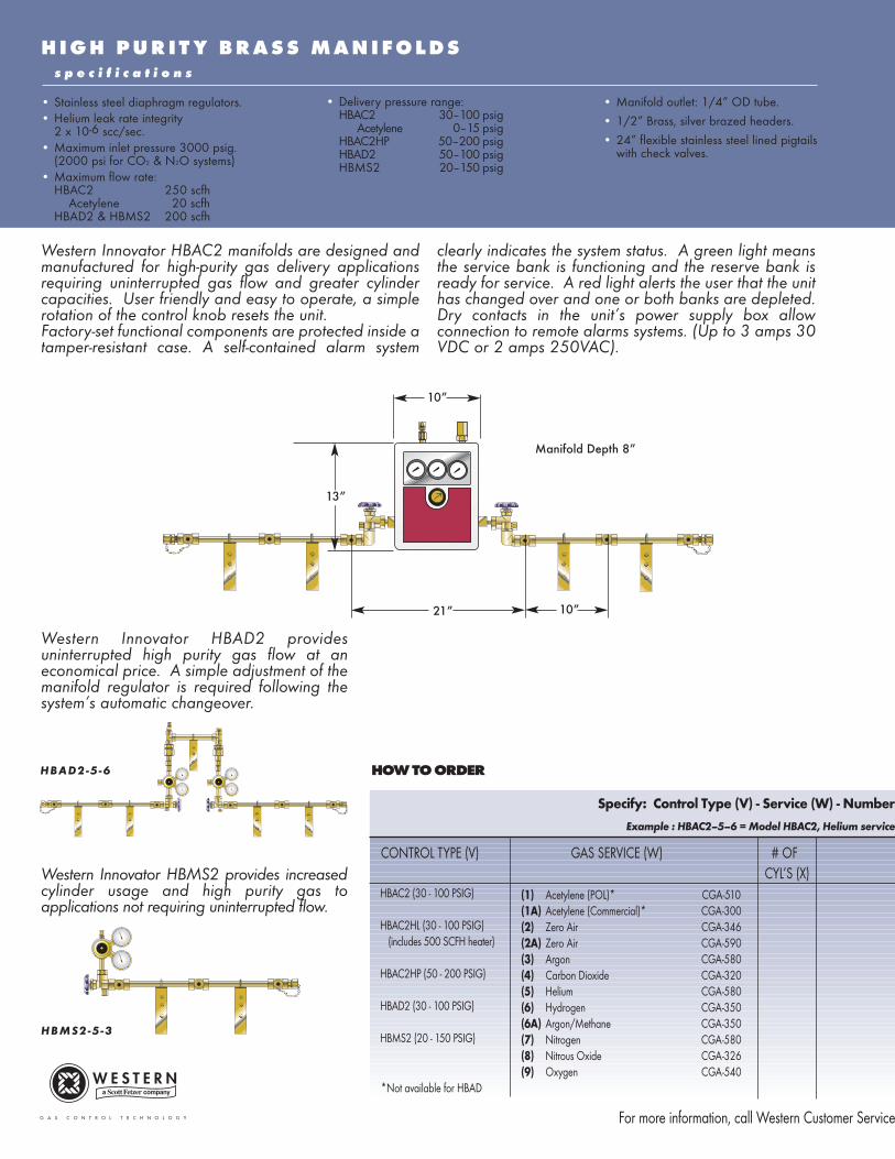
H I G H P U R I T Y B R A S S M A N I F O L D Ss p e c i f i c a t i o n s
• Stainless steel diaphragm regulators.• Helium leak rate integrity
2 x 10⁻⁶ scc/sec.• Maximum inlet pressure 3000 psig.
(2000 psi for CO2 & N2O systems)• Maximum flow rate:
HBAC2 250 scfhAcetylene 20 scfh
HBAD2 & HBMS2 200 scfh
HBMS2-5 -3
HBAD2-5 -6
10”
13”
21” 10”
• Manifold outlet: 1/4” OD tube.
• 1/2” Brass, silver brazed headers.
• 24” flexible stainless steel lined pigtails with check valves.
Western Innovator HBAC2 manifolds are designed andmanufactured for high-purity gas delivery applicationsrequiring uninterrupted gas flow and greater cylindercapacities. User friendly and easy to operate, a simplerotation of the control knob resets the unit. Factory-set functional components are protected inside atamper-resistant case. A self-contained alarm system
clearly indicates the system status. A green light meansthe service bank is functioning and the reserve bank isready for service. A red light alerts the user that the unithas changed over and one or both banks are depleted.Dry contacts in the unit’s power supply box allowconnection to remote alarms systems. (Up to 3 amps 30VDC or 2 amps 250VAC).
Western Innovator HBAD2 providesuninterrupted high purity gas flow at aneconomical price. A simple adjustment of themanifold regulator is required following thesystem’s automatic changeover.
Western Innovator HBMS2 provides increasedcylinder usage and high purity gas toapplications not requiring uninterrupted flow.
• Delivery pressure range:HBAC2 30–100 psig
Acetylene 0–15 psigHBAC2HP 50–200 psigHBAD2 50–100 psigHBMS2 20–150 psig
Manifold Depth 8”
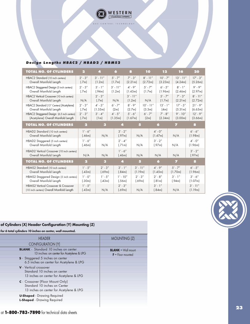
of Cylinders (X) Header Configuration (Y) Mounting (Z)
for 6 total cylinders 10 inches on center, wall mounted.
HEADER MOUNTING (Z) CONFIGURATION (Y)
BLANK = Wall mountF = Floor mounted
at 1-800-783-7890 for technical data sheets23
BLANK - Standard 10 inches on center13 inches on center for Acetylene & LPG
V - Vertical crossoverStandard 10 inches on center13 inches on center for Acetylene & LPG
S - Staggered 5 inches on center6.5 inches on center for Acetylene & LPG
C - Crossover (Floor Mount Only)Standard 10 inches on Center13 inches on center for Acetylene & LPG
U-Shaped - Drawing RequiredL-Shaped - Drawing Required
TOTAL NO. OF CYLINDERS 2 4 6 8 10 12 16 20
HBAC2 Standard (10 inch centers) 2’ - 3” 3’ - 11” 5’ - 7” 7’ - 3” 8’ - 11” 10’ - 7” 13’ - 11” 17’ - 3”Overall Manifold Length (.7m) (1.2m) (1.7m) (2.21m) (2.72m) (3.23m) (4.24m) (5.26m)
HBAC2 Staggered Design (5 inch centers) 2’ - 3” 3’ - 1” 3’ - 11” 4’ - 9” 5’ - 7” 6’ - 5” 8’ - 1” 9’ - 9”Overall Manifold Length (.7m) (.94m) (1.2m) (1.45m) (1.7m) (1.96m) (2.46m) (2.97m)
HBAC2 Vertical Crossover (10 inch centers) 2’ - 3” 3’ - 11” 5’ - 7” 7’ - 3” 8’ - 11”Overall Manifold Length N/A (.7m) N/A (1.2m) N/A (1.7m) (2.21m) (2.72m)
HBAC2 Standard (13” Centers) (Acetylene) 2’ - 3” 4’ - 5” 6’ - 7” 8’ - 9” 10’ - 11” 13’ - 1” 17’ - 5” 21’ - 9”Overall Manifold Length (.7m) (1.35m) (2m) (2.7m) (3.3m) (4m) (5.31m) (6.63m)
HBAC2 Staggered Design (6.5 inch centers) 2’ - 3” 3’ - 4” 4’ - 5” 5’ - 6” 6’ - 7” 7’ - 8” 9’ - 10” 12’ - 9”(Acetylene) Overall Manifold Length (.7m) (1m) (1.35m) (1.67m) (2m) (2.34m) (3.00m) (3.66m)
HBAD2 Standard (10 inch centers) 1’ - 6” 3’ - 2” 4’ - 0” 6’ - 6”Overall Manifold Length (.46m) N/A (.97m) N/A (1.47m) N/A (1.98m)
HBAD2 Staggered (5 inch centers) 1’ - 6” 2’ - 4” 3’ - 2” 4’ - 0”Overall Manifold Length (.46m) N/A (.71m) N/A (.97m) N/A (1.96m)
HBAD2 Vertical Crossover (10 inch centers) 1’ - 6” 3’ - 2”Overall Manifold Length N/A N/A (.46m) N/A N/A N/A (.97m)
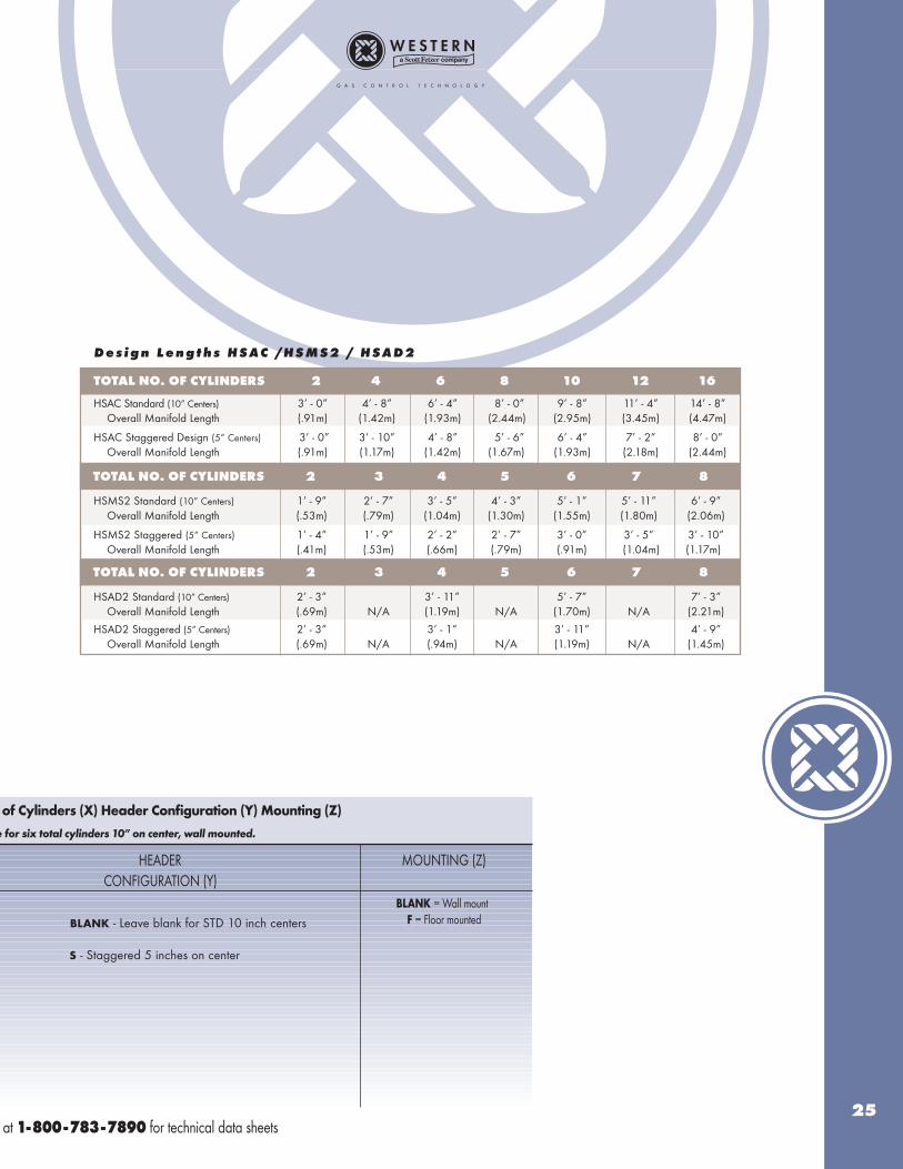
D e s i g n L e n g t h s H B A C 2 / H B A D 2 / H B M S 2
TOTAL NO. OF CYLINDERS 2 3 4 5 6 7 8
HBMS2 Standard (10 inch centers) 1’ - 5” 2’ - 3” 3’ - 1” 3’ - 11” 4’ - 9” 5’ - 7” 6’ - 5”Overall Manifold Length (.43m) (.69m) (.84m) (1.19m) (1.45m) (1.70m) (1.96m)
HBMS2 Staggered Design (5 inch centers) 1’ - 0” 1’ - 5” 1’ - 10” 2’ - 3” 2’ - 8” 3’ - 1” 3’ - 6”Overall Manifold Length (.30m) (.43m) (.56m) (.69m) (.81m) (.94m) (1.07m)
HBMS2 Vertical Crossover & Crossover 1’ - 5” 2’ - 3” 3’ - 1” 3’ - 11”(10 inch centers) Overall Manifold Length (.43m) N/A (.69m) N/A (.84m) N/A (1.19m)
TOTAL NO. OF CYLINDERS 2 3 4 5 6 7 8
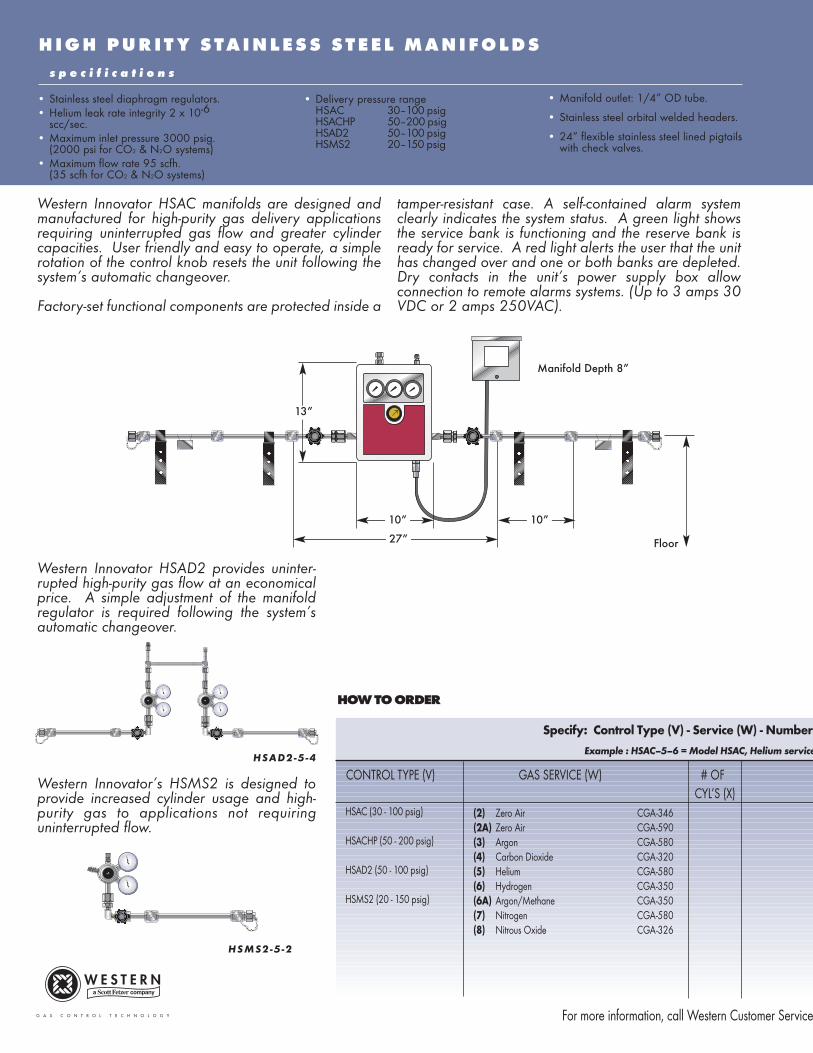
H I G H P U R I T Y S T A I N L E S S S T E E L M A N I F O L D S
HSMS2-5 -2
s p e c i f i c a t i o n s
• Stainless steel diaphragm regulators.• Helium leak rate integrity 2 x 10⁻⁶
scc/sec.• Maximum inlet pressure 3000 psig.
(2000 psi for CO2 & N2O systems)• Maximum flow rate 95 scfh.
(35 scfh for CO2 & N2O systems)
Western Innovator HSAC manifolds are designed andmanufactured for high-purity gas delivery applicationsrequiring uninterrupted gas flow and greater cylindercapacities. User friendly and easy to operate, a simplerotation of the control knob resets the unit following thesystem’s automatic changeover.
Factory-set functional components are protected inside a
tamper-resistant case. A self-contained alarm systemclearly indicates the system status. A green light showsthe service bank is functioning and the reserve bank isready for service. A red light alerts the user that the unithas changed over and one or both banks are depleted.Dry contacts in the unit’s power supply box allowconnection to remote alarms systems. (Up to 3 amps 30VDC or 2 amps 250VAC).
• Delivery pressure rangeHSAC 30–100 psigHSACHP 50–200 psigHSAD2 50–100 psigHSMS2 20–150 psig
• Manifold outlet: 1/4” OD tube.
• Stainless steel orbital welded headers.
• 24” flexible stainless steel lined pigtails with check valves.
Specify: Control Type (V) - Service (W) - Number
Example : HSAC–5–6 = Model HSAC, Helium service
CONTROL TYPE (V) GAS SERVICE (W) # OF CYL’S (X)
(2) Zero Air CGA-346(2A) Zero Air CGA-590(3) Argon CGA-580(4) Carbon Dioxide CGA-320(5) Helium CGA-580(6) Hydrogen CGA-350(6A) Argon/Methane CGA-350(7) Nitrogen CGA-580(8) Nitrous Oxide CGA-326
For more information, call Western Customer Service
HSAC (30 - 100 psig)
HSACHP (50 - 200 psig)
HSAD2 (50 - 100 psig)
HSMS2 (20 - 150 psig)
HOW TO ORDER
Western Innovator HSAD2 provides uninter-rupted high-purity gas flow at an economicalprice. A simple adjustment of the manifoldregulator is required following the system’sautomatic changeover.
Western Innovator’s HSMS2 is designed toprovide increased cylinder usage and high-purity gas to applications not requiringuninterrupted flow.
13”
10” 10”
27” Floor
HSAD2-5 -4
Manifold Depth 8”
of Cylinders (X) Header Configuration (Y) Mounting (Z)
e for six total cylinders 10” on center, wall mounted.
HEADER MOUNTING (Z) CONFIGURATION (Y)
at 1-800-783-7890 for technical data sheets25
BLANK - Leave blank for STD 10 inch centers
S - Staggered 5 inches on center
TOTAL NO. OF CYLINDERS 2 4 6 8 10 12 16
HSAC Standard (10” Centers) 3’ - 0” 4’ - 8” 6’ - 4” 8’ - 0” 9’ - 8” 11’ - 4” 14’ - 8”Overall Manifold Length (.91m) (1.42m) (1.93m) (2.44m) (2.95m) (3.45m) (4.47m)
HSAC Staggered Design (5” Centers) 3’ - 0” 3’ - 10” 4’ - 8” 5’ - 6” 6’ - 4” 7’ - 2” 8’ - 0”Overall Manifold Length (.91m) (1.17m) (1.42m) (1.67m) (1.93m) (2.18m) (2.44m)
HSMS2 Standard (10” Centers) 1’ - 9” 2’ - 7” 3’ - 5” 4’ - 3” 5’ - 1” 5’ - 11” 6’ - 9”Overall Manifold Length (.53m) (.79m) (1.04m) (1.30m) (1.55m) (1.80m) (2.06m)
HSMS2 Staggered (5” Centers) 1’ - 4” 1’ - 9” 2’ - 2” 2’ - 7” 3’ - 0” 3’ - 5” 3’ - 10”Overall Manifold Length (.41m) (.53m) (.66m) (.79m) (.91m) (1.04m) (1.17m)
HSAD2 Standard (10” Centers) 2’ - 3” 3’ - 11” 5’ - 7” 7’ - 3”Overall Manifold Length (.69m) N/A (1.19m) N/A (1.70m) N/A (2.21m)
HSAD2 Staggered (5” Centers) 2’ - 3” 3’ - 1” 3’ - 11” 4’ - 9”Overall Manifold Length (.69m) N/A (.94m) N/A (1.19m) N/A (1.45m)
D e s i g n L e n g t h s H S A C / H S M S 2 / H S A D 2
TOTAL NO. OF CYLINDERS 2 3 4 5 6 7 8
BLANK = Wall mountF = Floor mounted
TOTAL NO. OF CYLINDERS 2 3 4 5 6 7 8
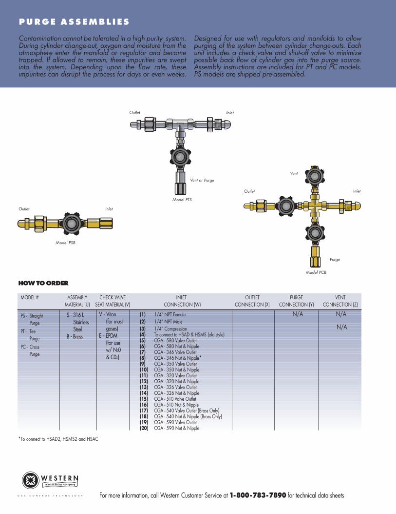
P U R G E A S S E M B L I E S
Contamination cannot be tolerated in a high purity system.During cylinder change-out, oxygen and moisture from theatmosphere enter the manifold or regulator and becometrapped. If allowed to remain, these impurities are sweptinto the system. Depending upon the flow rate, theseimpurities can disrupt the process for days or even weeks.
Designed for use with regulators and manifolds to allowpurging of the system between cylinder change-outs. Eachunit includes a check valve and shut-off valve to minimizepossible back flow of cylinder gas into the purge source.Assembly instructions are included for PT and PC models.PS models are shipped pre-assembled.
MODEL # ASSEMBLY CHECK VALVE INLET OUTLET PURGE VENTMATERIAL (U) SEAT MATERIAL (V) CONNECTION (W) CONNECTION (X) CONNECTION (Y) CONNECTION (Z)
N/A N/A
N/A
*To connect to HSAD2, HSMS2 and HSAC
HOW TO ORDER
PS - StraightPurge
PT - TeePurge
PC - CrossPurge
Outlet
Model PSB
Inlet
Outlet
Model PTS
Inlet
Vent or Purge
Outlet
Model PCB
Inlet
Vent
Purge
V - Viton(for mostgases)
E - EPDM(for usew/ N20& C02)
S - 316 LStainlessSteel
B - Brass
(1) 1/4” NPT Female(2) 1/4” NPT Male(3) 1/4” Compression(4) To connect to HSAD & HSMS (old style)(5) CGA - 580 Valve Outlet(6) CGA - 580 Nut & Nipple(7) CGA - 346 Valve Outlet(8) CGA - 346 Nut & Nipple*(9) CGA - 350 Valve Outlet(10) CGA - 350 Nut & Nipple(11) CGA - 320 Valve Outlet(12) CGA - 320 Nut & Nipple(13) CGA - 326 Valve Outlet(14) CGA - 326 Nut & Nipple(15) CGA - 510 Valve Outlet(16) CGA - 510 Nut & Nipple(17) CGA - 540 Valve Outlet (Brass Only)(18) CGA - 540 Nut & Nipple (Brass Only)(19) CGA - 590 Valve Outlet(20) CGA - 590 Nut & Nipple
For more information, call Western Customer Service at 1-800-783-7890 for technical data sheets
AAAACCCCCCCCEEEESSSSSSSSOOOORRRRIIIIEEEESSSS
MOUNTING ACCESSORIES
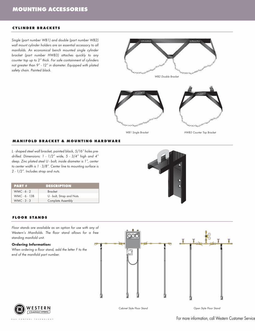
Single (part number WB1) and double (part number WB2)wall mount cylinder holders are an essential accessory to allmanifolds. An economical bench mounted single cylinderbracket (part number HWB3) attaches quickly to anycounter top up to 2” thick. For safe containment of cylindersnot greater than 9” - 12” in diameter. Equipped with platedsafety chain. Painted black.
L - shaped steel wall bracket, painted black, 5/16” holes pre-drilled. Dimensions: 1 - 1/2” wide, 5 - 3/4” high and 4”deep. Zinc plated steel U - bolt, inside diameter is 1”, centerto center width is 1 - 3/8”. Center line to mounting surface is2 - 1/2”. Includes strap and nuts.
M A N I F O L D B R AC K E T & M O U N T I N G H A R DWA R E
WB1 Single Bracket
WB2 Double Bracket
HWB3 Counter Top Bracket
PART # DESCRIPTION
WMC - 6 - 2 BracketWMC - 6 - 13B U - bolt, Strap and NutsWMC - 3 - 3 Complete Assembly
Floor stands are available as an option for use with any ofWestern’s Manifolds. The floor stand allows for a freestanding manifold unit.
F L O O R S T A N D S
Ordering Information:
When ordering a floor stand, add the letter F to theend of the manifold part number.
Cabinet Style Floor Stand Open Style Floor Stand
For more information, call Western Customer Service
C Y L I N D E R B R AC K E T S
29
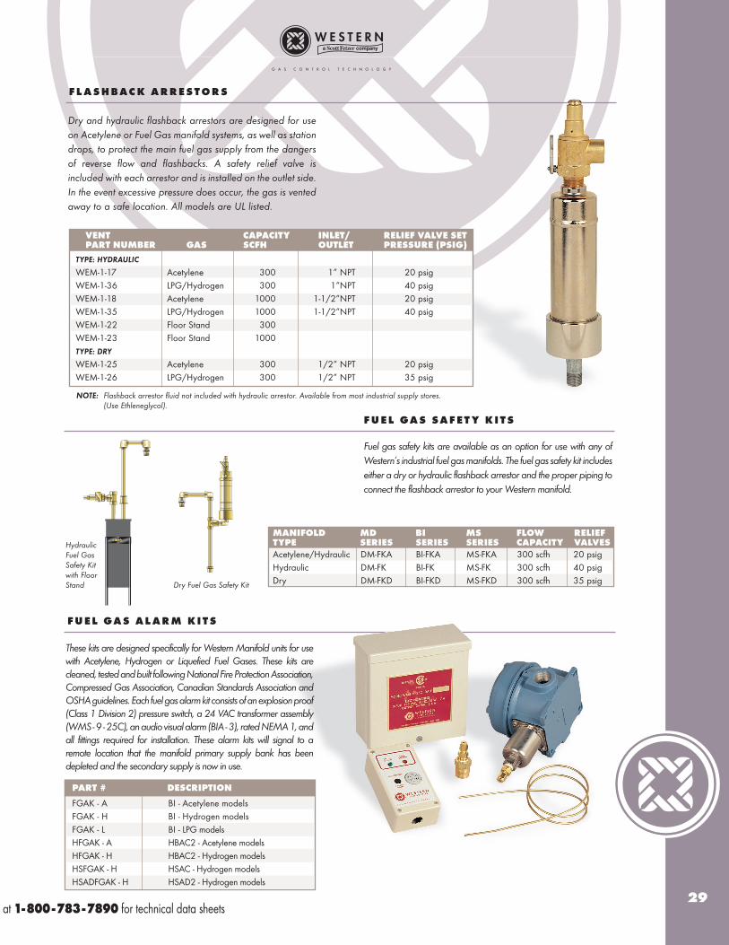
Dry and hydraulic flashback arrestors are designed for useon Acetylene or Fuel Gas manifold systems, as well as stationdrops, to protect the main fuel gas supply from the dangersof reverse flow and flashbacks. A safety relief valve isincluded with each arrestor and is installed on the outlet side.In the event excessive pressure does occur, the gas is ventedaway to a safe location. All models are UL listed.
VENT CAPACITY INLET/ RELIEF VALVE SETPART NUMBER GAS SCFH OUTLET PRESSURE (PSIG)
TYPE: HYDRAULIC
WEM-1-17 Acetylene 300 1” NPT 20 psigWEM-1-36 LPG/Hydrogen 300 1”NPT 40 psigWEM-1-18 Acetylene 1000 1-1/2”NPT 20 psigWEM-1-35 LPG/Hydrogen 1000 1-1/2”NPT 40 psigWEM-1-22 Floor Stand 300WEM-1-23 Floor Stand 1000TYPE: DRY
WEM-1-25 Acetylene 300 1/2” NPT 20 psigWEM-1-26 LPG/Hydrogen 300 1/2” NPT 35 psig
NOTE: Flashback arrestor fluid not included with hydraulic arrestor. Available from most industrial supply stores. (Use Ethleneglycol).
F L A S H B AC K A R R E S T O R S
F U E L GA S S A F E T Y K I T S
Fuel gas safety kits are available as an option for use with any ofWestern’s industrial fuel gas manifolds. The fuel gas safety kit includeseither a dry or hydraulic flashback arrestor and the proper piping toconnect the flashback arrestor to your Western manifold.
MANIFOLD MD BI MS FLOW RELIEFTYPE SERIES SERIES SERIES CAPACITY VALVES
Acetylene/Hydraulic DM-FKA BI-FKA MS-FKA 300 scfh 20 psigHydraulic DM-FK BI-FK MS-FK 300 scfh 40 psigDry DM-FKD BI-FKD MS-FKD 300 scfh 35 psig
HydraulicFuel GasSafety Kitwith FloorStand Dry Fuel Gas Safety Kit
PART # DESCRIPTION
FGAK - A BI - Acetylene modelsFGAK - H BI - Hydrogen modelsFGAK - L BI - LPG modelsHFGAK - A HBAC2 - Acetylene modelsHFGAK - H HBAC2 - Hydrogen modelsHSFGAK - H HSAC - Hydrogen modelsHSADFGAK - H HSAD2 - Hydrogen models
These kits are designed specifically for Western Manifold units for usewith Acetylene, Hydrogen or Liquefied Fuel Gases. These kits arecleaned, tested and built following National Fire Protection Association,Compressed Gas Association, Canadian Standards Association andOSHA guidelines. Each fuel gas alarm kit consists of an explosion proof(Class 1 Division 2) pressure switch, a 24 VAC transformer assembly(WMS - 9 - 25C), an audio visual alarm (BIA - 3), rated NEMA 1, andall fittings required for installation. These alarm kits will signal to aremote location that the manifold primary supply bank has beendepleted and the secondary supply is now in use.
F U E L GA S A L A R M K I T S
at 1-800-783-7890 for technical data sheets

PRESSURE SWITCHES, REMOTE ALARMS AND POWER SUPPLIES
Designed for use with gas pressure manifolds to activate remote alarmsystems. Operates when cylinder/line pressure is below minimum pres-sure setting. High/Low switches have two activation points. Availablefor explosion proof or general purpose service. Electrical rating for allswitches is SPDT 15 amps 24/125/250/480 VAC resistive. CSAapproved. Pressure port connection 1/4” NPT.
PART DESCRIPTION PRESSURE MAXIMUM WETTED ENCLOSURE ELECTERICALNUMBER RANGE (PSIG) INLET (PSIG) MATERIALS CLASSIFICATIONS CONNECTION
WME-4-5 Explosion Proof 30-300 800 S.S. Bellows NEMA 4, 7, 9, IP66 3/4” NPTWME-4-6 Explosion Proof 5-50 75 Brass Bellows NEMA 4, 7, 9, IP66 3/4” NPTWME-4-9 General Purpose 100-1000 10,000 S.S. Piston & BUNA "N" o-ring NEMA 4 1/2” NPTWME-4-10 General Purpose 200-3000 10,000 S.S. Piston & BUNA "N" o-ring NEMA 4 1/2” NPTWME-4-13 High/Low Switch 0-300 350 Phosphor Bronze Bellows NEMA 4 7/8” Dia. KnockoutWME-4-14 General Purpose 20-200 250 Phosphor Bronze Bellows NEMA 4 1/2” NPT & 7/8 Dia. KnockoutWME-4-15 High/Low Switch 0-100 125 Brass Bellows NEMA 4, 7, 9, IP66 7/8” Dia. KnockoutWME-4-16 General Purpose 20-200 250 316 S.S. Bellows NEMA 4 1/2” NPT FemaleWME-4-17 General Purpose 100-1700 2500 316 S.S. Bellows NEMA 4 1/2” NPT FemaleWME-4-18 High/Low Switch 20-200 250 316 S.S. Bellows NEMA 4 7/8” Dia. KnockoutsWME-4-20 High/Low Explosion Proof 0-100 125 Brass Bellows NEMA 4, 7, 9, IP66 3/4” NPT Female
S p e c i f i c a t i o n s a n d O r d e r i n g I n f o r m a t i o n G u i d e l i n e s
NOTE: 1/4” NPT female pressure connection. Switches may be wired "normally open" or "normally closed".
Visual Alarm Panel - Contains green LED to indicate “service”side is in use and red LED to indicate control unit has switched to“secondary” side. Audio/Visual Alarm Panel - Contains red andgreen alarm lights and buzzer with “squelch” button.Green light remains illuminated while “service” bank is inuse. When “service” bank is exhausted, green light isextinguished, red light is lighted plus buzzer, rated 75decibels within 100 centimeters, is activated to ensurenotice of the alarm conditions. A touch of the squelchbutton silences the buzzer, but the red alarm light willremain illuminated until the exhausted bank has beenreplaced. Two Gas Audio/Visual Alarm Panel - Asabove, but warning alarm lights and buzzer for twogases in a single box, i.e. Oxygen and Nitrogen, etc.
All panels may be for either exposed or flush mounting.Available in 24 VAC service only. Alarm dimensions: 4-3/4”H x2-9/16”W x 1-5/8”D. For open style manifolds, a 115/24 VACpower supply part number WMS-9-25C is required.
R E M O T E A L A R M PA N E L S
PART NUMBER DESCRIPTION
BIA - 1 Visual Alarm, 24 VACBIA - 2 Two Gas Audio/Visual Alarm, 24 VACBIA - 3 Audio/Visual Alarm, 24 VAC
P OW E R S U P P L I E S
Utilized with remote alarm panels, reduces 115 VAC to 24 VAC. A cir-cuit board in the power supply isolates remote alarms regardless ofvoltage (up to 3 amps 30 VDC or 2 amps 250 VAC). Dimensions:6-1/4” x 4”. Rated NEMA 3R, CSA approved.
PART NUMBER DESCRIPTION
WMS - 9-25C For use with SD, MS, MD, AD and LA8570D For use with BI, LC, HBAC2 and HSAC
cabinet style manifold
For more information, call Western Customer Service
P R E S S U R E S W I T C H E S
Model BIA-3
31
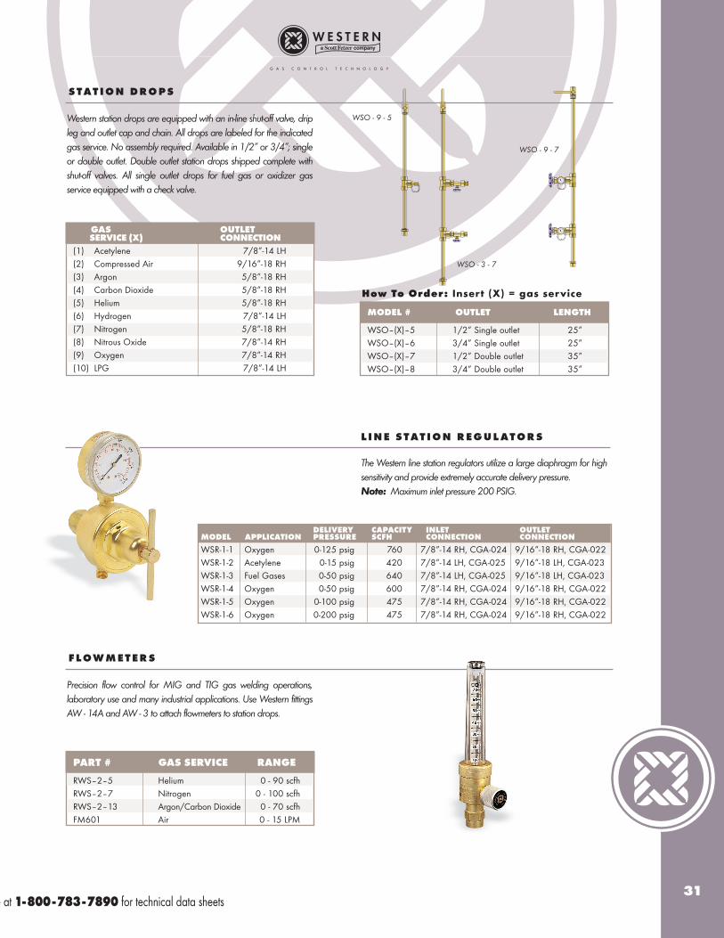
GAS OUTLETSERVICE (X) CONNECTION
(1) Acetylene 7/8”-14 LH(2) Compressed Air 9/16”-18 RH(3) Argon 5/8”-18 RH(4) Carbon Dioxide 5/8”-18 RH(5) Helium 5/8”-18 RH(6) Hydrogen 7/8”-14 LH(7) Nitrogen 5/8”-18 RH(8) Nitrous Oxide 7/8”-14 RH(9) Oxygen 7/8”-14 RH(10) LPG 7/8”-14 LH
Western station drops are equipped with an in-line shut-off valve, dripleg and outlet cap and chain. All drops are labeled for the indicatedgas service. No assembly required. Available in 1/2” or 3/4”; singleor double outlet. Double outlet station drops shipped complete withshut-off valves. All single outlet drops for fuel gas or oxidizer gasservice equipped with a check valve.
S T AT I O N D RO P S
MODEL # OUTLET LENGTH
WSO–(X)–5 1/2” Single outlet 25”WSO–(X)–6 3/4” Single outlet 25”WSO–(X)–7 1/2” Double outlet 35”WSO–(X)–8 3/4” Double outlet 35”
How To Order: Insert (X) = gas service
L I N E S T AT I O N R E G U L AT O R S
The Western line station regulators utilize a large diaphragm for highsensitivity and provide extremely accurate delivery pressure. Note: Maximum inlet pressure 200 PSIG.
DELIVERY CAPACITY INLET OUTLET MODEL APPLICATION PRESSURE SCFH CONNECTION CONNECTION
WSR-1-1 Oxygen 0-125 psig 760 7/8”-14 RH, CGA-024 9/16”-18 RH, CGA-022WSR-1-2 Acetylene 0-15 psig 420 7/8”-14 LH, CGA-025 9/16”-18 LH, CGA-023WSR-1-3 Fuel Gases 0-50 psig 640 7/8”-14 LH, CGA-025 9/16”-18 LH, CGA-023WSR-1-4 Oxygen 0-50 psig 600 7/8”-14 RH, CGA-024 9/16”-18 RH, CGA-022WSR-1-5 Oxygen 0-100 psig 475 7/8”-14 RH, CGA-024 9/16”-18 RH, CGA-022WSR-1-6 Oxygen 0-200 psig 475 7/8”-14 RH, CGA-024 9/16”-18 RH, CGA-022
PART # GAS SERVICE RANGE
RWS–2–5 Helium 0 - 90 scfhRWS–2–7 Nitrogen 0 - 100 scfhRWS–2–13 Argon/Carbon Dioxide 0 - 70 scfhFM601 Air 0 - 15 LPM
Precision flow control for MIG and TIG gas welding operations,laboratory use and many industrial applications. Use Western fittingsAW - 14A and AW - 3 to attach flowmeters to station drops.
F L OW M E T E R S
WSO - 9 - 5
WSO - 3 - 7
WSO - 9 - 7
e at 1-800-783-7890 for technical data sheets
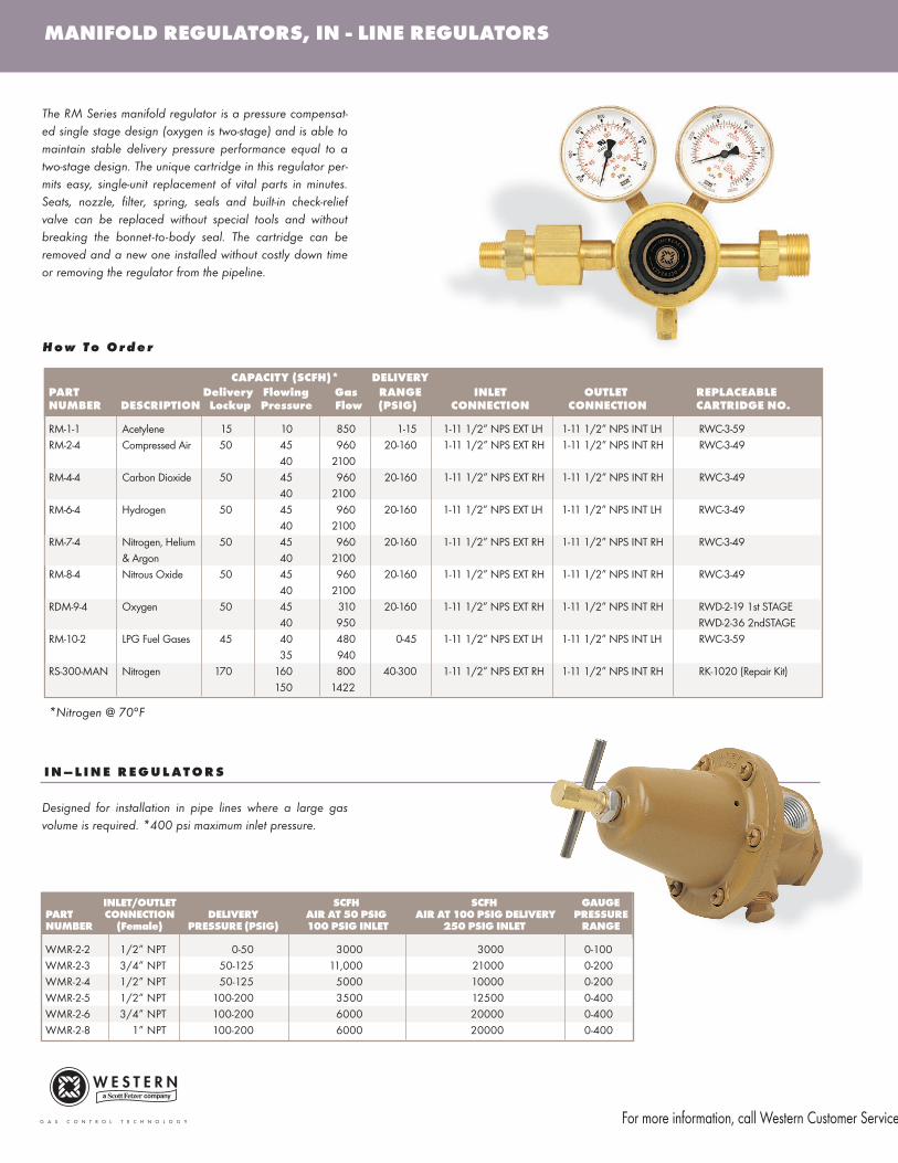
MANIFOLD REGULATORS, IN - LINE REGULATORS
The RM Series manifold regulator is a pressure compensat-ed single stage design (oxygen is two-stage) and is able tomaintain stable delivery pressure performance equal to atwo-stage design. The unique cartridge in this regulator per-mits easy, single-unit replacement of vital parts in minutes.Seats, nozzle, filter, spring, seals and built-in check-reliefvalve can be replaced without special tools and withoutbreaking the bonnet-to-body seal. The cartridge can beremoved and a new one installed without costly down timeor removing the regulator from the pipeline.
H o w T o O r d e r
Designed for installation in pipe lines where a large gasvolume is required. *400 psi maximum inlet pressure.
I N – L I N E R E G U L AT O R S
*Nitrogen @ 70°F
CAPACITY (SCFH)* DELIVERY
PART Delivery Flowing Gas RANGE INLET OUTLET REPLACEABLENUMBER DESCRIPTION Lockup Pressure Flow (PSIG) CONNECTION CONNECTION CARTRIDGE NO.
RM-1-1 Acetylene 15 10 850 1-15 1-11 1/2” NPS EXT LH 1-11 1/2” NPS INT LH RWC-3-59RM-2-4 Compressed Air 50 45 960 20-160 1-11 1/2” NPS EXT RH 1-11 1/2” NPS INT RH RWC-3-49
40 2100RM-4-4 Carbon Dioxide 50 45 960 20-160 1-11 1/2” NPS EXT RH 1-11 1/2” NPS INT RH RWC-3-49
40 2100RM-6-4 Hydrogen 50 45 960 20-160 1-11 1/2” NPS EXT LH 1-11 1/2” NPS INT LH RWC-3-49
40 2100RM-7-4 Nitrogen, Helium 50 45 960 20-160 1-11 1/2” NPS EXT RH 1-11 1/2” NPS INT RH RWC-3-49
& Argon 40 2100RM-8-4 Nitrous Oxide 50 45 960 20-160 1-11 1/2” NPS EXT RH 1-11 1/2” NPS INT RH RWC-3-49
40 2100RDM-9-4 Oxygen 50 45 310 20-160 1-11 1/2” NPS EXT RH 1-11 1/2” NPS INT RH RWD-2-19 1st STAGE
40 950 RWD-2-36 2ndSTAGERM-10-2 LPG Fuel Gases 45 40 480 0-45 1-11 1/2” NPS EXT LH 1-11 1/2” NPS INT LH RWC-3-59
35 940RS-300-MAN Nitrogen 170 160 800 40-300 1-11 1/2” NPS EXT RH 1-11 1/2” NPS INT RH RK-1020 (Repair Kit)
150 1422
INLET/OUTLET SCFH SCFH GAUGEPART CONNECTION DELIVERY AIR AT 50 PSIG AIR AT 100 PSIG DELIVERY PRESSURE NUMBER (Female) PRESSURE (PSIG) 100 PSIG INLET 250 PSIG INLET RANGE
WMR-2-2 1/2” NPT 0-50 3000 3000 0-100WMR-2-3 3/4” NPT 50-125 11,000 21000 0-200WMR-2-4 1/2” NPT 50-125 5000 10000 0-200WMR-2-5 1/2” NPT 100-200 3500 12500 0-400WMR-2-6 3/4” NPT 100-200 6000 20000 0-400WMR-2-8 1” NPT 100-200 6000 20000 0-400
For more information, call Western Customer Service
33
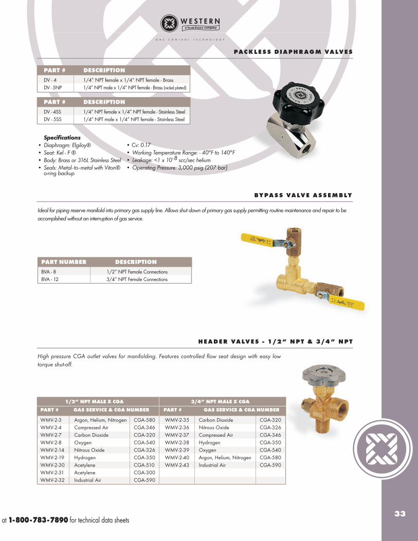
PAC K L E S S D I A P H R AG M VA LV E S
BY PA S S VA LV E A S S E M B LY
Ideal for piping reserve manifold into primary gas supply line. Allows shut down of primary gas supply permitting routine maintenance and repair to beaccomplished without an interruption of gas service.
PART # DESCRIPTION
DV - 4 1/4” NPT female x 1/4” NPT female - BrassDV - 5NP 1/4” NPT male x 1/4” NPT female - Brass (nickel plated)
PART NUMBER DESCRIPTION
BVA - 8 1/2” NPT Female ConnectionsBVA - 12 3/4” NPT Female Connections
H E A D E R VA LV E S - 1 / 2 ” N P T & 3 / 4 ” N P T
High pressure CGA outlet valves for manifolding. Features controlled flow seat design with easy lowtorque shut-off.
1/2” NPT MALE X CGA 3/4” NPT MALE X CGA
PART # GAS SERVICE & CGA NUMBER PART # GAS SERVICE & CGA NUMBER
WMV-2-3 Argon, Helium, Nitrogen CGA-580 WMV-2-35 Carbon Dioxide CGA-320WMV-2-4 Compressed Air CGA-346 WMV-2-36 Nitrous Oxide CGA-326WMV-2-7 Carbon Dioxide CGA-320 WMV-2-37 Compressed Air CGA-346WMV-2-8 Oxygen CGA-540 WMV-2-38 Hydrogen CGA-350WMV-2-14 Nitrous Oxide CGA-326 WMV-2-39 Oxygen CGA-540WMV-2-19 Hydrogen CGA-350 WMV-2-40 Argon, Helium, Nitrogen CGA-580WMV-2-30 Acetylene CGA-510 WMV-2-43 Industrial Air CGA-590WMV-2-31 Acetylene CGA-300WMV-2-32 Industrial Air CGA-590
PART # DESCRIPTION
DV - 4SS 1/4” NPT female x 1/4” NPT female - Stainless SteelDV - 5SS 1/4” NPT male x 1/4” NPT female - Stainless Steel
Specifications
• Diaphragm: Elgiloy®• Seat: Kel - F ®• Body: Brass or 316L Stainless Steel• Seals: Metal - to -metal with Viton®
o-ring backup
• Cv: 0.17• Working Temperature Range: - 40°F to 140°F• Leakage: <1 x 10⁻⁸ scc/sec helium• Operating Pressure: 3,000 psig (207 bar)
at 1-800-783-7890 for technical data sheets
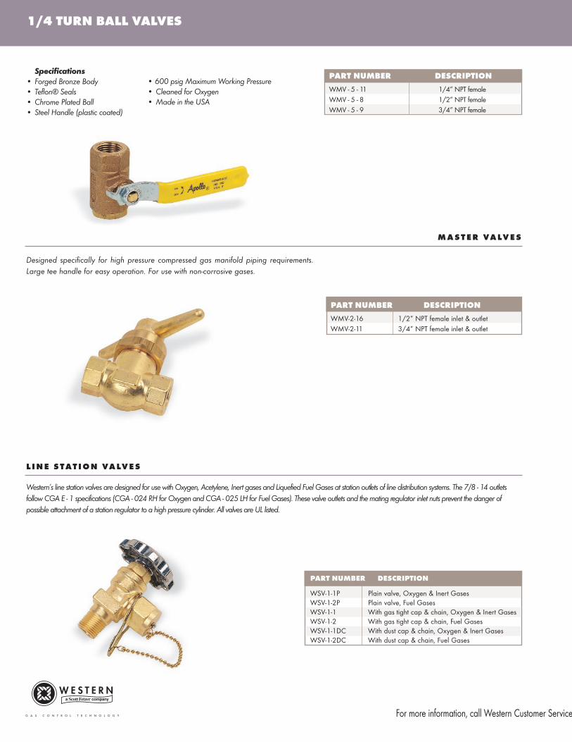
1/4 TURN BALL VALVES
Designed specifically for high pressure compressed gas manifold piping requirements.Large tee handle for easy operation. For use with non-corrosive gases.
M A S T E R VA LV E S
PART NUMBER DESCRIPTION
WMV - 5 - 11 1/4” NPT female WMV - 5 - 8 1/2” NPT femaleWMV - 5 - 9 3/4” NPT female
PART NUMBER DESCRIPTION
WMV-2-16 1/2” NPT female inlet & outletWMV-2-11 3/4” NPT female inlet & outlet
PART NUMBER DESCRIPTION
WSV-1-1P Plain valve, Oxygen & Inert GasesWSV-1-2P Plain valve, Fuel GasesWSV-1-1 With gas tight cap & chain, Oxygen & Inert Gases WSV-1-2 With gas tight cap & chain, Fuel GasesWSV-1-1DC With dust cap & chain, Oxygen & Inert GasesWSV-1-2DC With dust cap & chain, Fuel Gases
L I N E S T AT I O N VA LV E S
Western’s line station valves are designed for use with Oxygen, Acetylene, Inert gases and Liquefied Fuel Gases at station outlets of line distribution systems. The 7/8 - 14 outletsfollow CGA E - 1 specifications (CGA - 024 RH for Oxygen and CGA - 025 LH for Fuel Gases). These valve outlets and the mating regulator inlet nuts prevent the danger ofpossible attachment of a station regulator to a high pressure cylinder. All valves are UL listed.
Specifications
• Forged Bronze Body• Teflon® Seals• Chrome Plated Ball• Steel Handle (plastic coated)
• 600 psig Maximum Working Pressure• Cleaned for Oxygen• Made in the USA
For more information, call Western Customer Service
35
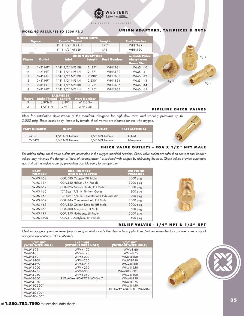
UNION ADAPTORS w/ Nickle Plated
Figure Outlet Inlet Length Part Number Phosphorous
Bronze Filter
2 1/2” NPT 1”-11 1/2” NPS RH 2.187” WHF-3-31 WMS-1-402 1/2” NPT 1”-11 1/2” NPS LH 2.187” WHF-3-32 WMS-1-412 3/4” NPT 1”-11 1/2” NPS RH 2.230” WHF-3-33 WMS-1-422 3/4” NPT 1”-11 1/2” NPS LH 2.230” WHF-3-34 WMS-1-432 3/8” NPT 1”-11 1/2” NPS RH 3.125” WHF-3-37 WMS-1-442 3/8” NPT 1”-11 1/2” NPS LH 3.125” WHF-3-38 WMS-1-45
WORKING PRESSURES TO 3000 PSIG
TAILPIECES Figure Male Thread Length Part Number
3 3/8”NPT 2.40” WHF-3-363 1/2” NPT 2.94” WHF-3-35
UNION NUTS Figure Female Thread Length Part Number
1 1”-11 1/2” NPS RH 1.75” WHF-3-291 1”-11 1/2” NPS LH 1.75” WHF-3-30
Ideal for installation downstream of the manifold, designed for high flow rates and working pressures up to3,000 psig. These brass body, female by female check valves are cleaned for use with oxygen.
P I P E L I N E C H E C K VA LV E S
PART NUMBER INLET OUTLET SEAT MATERIAL
CVF-8F 1/2” NPT Female 1/2” NPT Female EPDM CVF-12F 3/4” NPT Female 3/4” NPT Female Neoprene
For added safety, check valve outlets are assembled in the oxygen manifold headers. Check valve outlets are safer than conventional headervalves; they minimize the danger of “heat of recompression” associated with oxygen by disbursing the heat. Check valves provide automaticgas shut off if a pigtail ruptures, preventing possible injury to the operator.
C H E C K VA LV E O U T L E T S - C GA X 1 / 2 ” N P T M A L E
Fig. 1
Fig. 2
Fig. 3
PART CGA NUMBER WORKING NUMBER AND GAS SERVICE PRESSURE
WMS-1-53 CGA-540 Oxygen, RH Male 3000 psig WMS-1-54 CGA-580 Helium , RH Female 3000 psigWMS-1-59 CGA-326 Nitrous Oxide, RH Male 3000 psigWMS-1-60 “C” Size - 7/8-14 RH-Inert Gases 200 psigWMS-1-61 “C” Size - 7/8-14 LH Water and Industrial Air 200 psigWMS-1-62 CGA-346 Compressed Air, RH Male 3000 psigWMS-1-65 CGA-320 Carbon Dioxide, RH Male 3000 psigWMS-1-67 CGA-300 Acetylene, LH Male 500 psigWMS-1-99 CGA-350 Hydrogne, LH Male 3000 psigWMS-1-100 CGA-510 Acetylene, LH Female 500 psig
Ideal for cryogenic pressure vessel (vapor area), manifolds and other demanding applications. Not recommended for corrosive gases or liquidcryogenic applications.
R E L I E F VA LV E S - 1 / 4 ” N P T & 1 / 2 ” N P T
1/4” NPT 1/4” NPT 1/2” NPT (WITH WEEP HOLE) (WITHOUT WEEP HOLE) (WITHOUT WEEP HOLE)
WMV-4-22 WRV-4-100 WMV-8-60WMV-4-35 WRV-4-125 WMV-8-75WMV-4-50 WRV-4-200 WMV-8-100 WMV-4-100 WRV-4-230 WMV-8-150WMV-4-125 WRV-4-235 WMV-8-200WMV-4-200 WRV-4-250 WMV-8-250WMV-4-235 WRV-4-300 WMV-8C-300*WMV-4-250 WRV-4-350 WMV-8-300WMV-4-300 PIPE AWAY ADAPTOR: WMV-4-7 WMV-8-350WMV-4-350 WMV-8-375WMV-4C-350* WMV-8-450WMV-4-400 PIPE AWAY ADAPTOR : WMV-8-7WMV-4C-400*WMV-4C-450*
U N I O N A DA P T O R S , T A I L P I E C E S & N U T S
*CO2 Models
at 1-800-783-7890 for technical data sheets
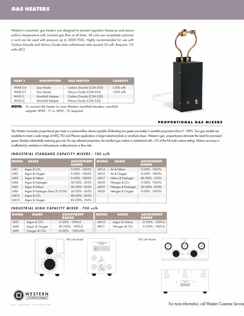
Western’s automatic gas heaters are designed to prevent regulator freeze-up and assureuniform temperature with constant gas flow at all times. All units are completely automat-ic and can be used with pressure up to 3000 PSIG. Highly recommended for use withCarbon Dioxide and Nitrous Oxide when withdrawal rates exceed 35 scfh. Requires 115volts (AC).
PART # DESCRIPTION GAS SERVICE CAPACITY
WME-3-4 Gas Heater Carbon Dioxide (CGA-320) 1,000 scfhWME-3-7 Gas Heater Nitrous Oxide (CGA-326) 1,000 scfhWHS-11 Manifold Adapter Carbon Dioxide (CGA-320)WHS-12 Manifold Adapter Nitrous Oxide (CGA-326)
NOTE: To connect the heater to most Western manifold headers, manifold adapter WHS - 11 or WHS - 12 required.
P RO P O R T I O N A L GA S M I X E R S
The Western Innovator proportional gas mixer is a pressure-flow device capable of blending two gases accurately in variable proportions from 0 - 100%. Two gas models areavailable to meet a wide range of MIG, TIG and Plasma applications in large industrial plants or small job shops. Western’s gas proportioners eliminate the need for pre-mixedgases, thereby substantially reducing gas cost. For any selected proportion, the resultant gas mixture is maintained with ±2% of the full scale mixture setting. Mixture accuracy isunaffected by variations in inlet pressure, outlet pressure or flow rate.
MODEL GASES ADJUSTMENT MODEL GASES ADJUSTMENTRANGE RANGE
MX1 Argon & CO2 0-100% - 100-0% MX14 Air & Helium 0-100% - 100-0%MX2 Argon & Oxygen 0-100% - 100-0% MX15 Air & Oxygen 0-100% - 100-0%MX3 Argon & Helium 0-100% - 100-0% MX17 Helium & Hydrogen 85-100% - 15-0%MX4 Argon & Hydrogen 50-100% - 50-0% MX18 Nitrogen & CO2 0-100% - 100-0%MX5 Argon & Helium 50-100% - 50-0% MX19 Nitrogen & Hydrogen 50-100% - 50-0%MX6 Argon & Hydrogen (Max 50 SCFH) 50-100% - 50-0% MX20 Nitrogen & Oxygen 0-100% - 100-0%MX12 Argon & CO2 80-100% - 20-0%MX13 Argon & Oxygen 85-100% - 15-0%
INDUSTRIAL STANDARD CAPACIT Y MIXERS - 180 sc fh
MODEL GASES ADJUSTMENT MODEL GASES ADJUSTMENTRANGE RANGE
MX7 Argon & CO2 0-100% - 100%-0 MX10 Argon & Helium 0-100% - 100%-0MX8 Argon & Oxygen 80-100% - 100%-0 MX11 Nitrogen & CO2 0-100% - 100%-0MX9 Oxygen & CO2 0-100% - 100%-0%
INDUSTRIAL HIGH CAPACIT Y MIXER - 700 sc fh
010
2030 40
5060
7080
90100
010
2030 40
50
70
100
OUTLET
INLET
CO2
ARGON
MODEL NO.
INLETOUTLETSERIAL NO.
PROPORTIONALMIXER
010
2030 40
5060
7080
90100
010
2030 40
5060
7080
90100
MODEL NO.
INLETOUTLETSERIAL NO.
PROPORTIONALMIXER
180 scfh Model 700 scfh Model
GAS HEATERS
For more information, call Western Customer Service

37
P O R T A B L E B U L K S U P P LY W I T H C Y L I N D E R R E S E RV E S U P P LY
B U L K S U P P LY W I T H C Y L I N D E R R E S E RV E
Note: Operating supply may consist of one or more supply units on each bank. (Liquid cylinders 250 PSIG)
WESTERNWMS - 1 - 20 WMS - 1 - 22DLA - 4 OR DLA - 5
Primary Supply Secondary Supply
WESTERNWME - 4 - 15 WME - 4 - 13High/Low Pressure Switch
WESTERNWMS - 1 - 20 WMS - 1 - 22DLA - 4 or DLA - 5
Reserve SupplyOperating Supply
WESTERNCheck ValveCVF - 8F or CVF - 12F
WESTERNLC Series or LCHP Series
Vent to Outside of Building
Pressure Relief Valve
WESTERNCLA SeriesCheck Valve
Cylinder Valve
ActuatingSwitch
Pressure Regulator
WESTERNActuating SwitchWME - 4 - 14(Emergency Reserve in Use)
WESTERNWME - 4 - 10Actuating Switch & WMS - 1 - 97(Emergency Reserve Low)
Cylinder Valve
WESTERNCheck ValveCVF - 8F orCVF - 12F
Pressure Regulator
Pressure Relief Device
Reserve Supply (High-Pressure Cylinders)
PressureRelief Device
Bleeder BackPressure ValveOperating Selector
SecondaryBank PressureRegulator
WESTERNWME - 4 - 14 (WME - 4 - 10 FOR N2)Actuating Switch (Emergency Reserve in Use)
50 to 55 PSIG
Pressure Relief Valve
To Outside of Building
WESTERNMS Series or CLA Series
PressureReliefDevice
ChangeoverActuating Switch(Secondary in Use)
Cylinder Valves
Check Valves
OperatingSupply Regulator
WESTERNCVF - 8F OR CVF - 12FCheck Valves
Reserve PressureRegulatorShutoff Valve
WESTERNWME - 4 - 15 WME - 4 - 13High/Low Pressure Switch
WESTERNWME - 4 - 9 or WME - 4 - 10(Emergency Reserve Low Switch)
at 1-800-783-7890 for technical data sheets

Pertinent Facts for Portable Bulk Containers
Western specializes in the manufacture and design of specific manifolds to customers’ applications. If you have a requirement for a unique manifold system or a unit to fit intolimited room dimensions, contact a Western supplier for a custom designed system.
Nominal extra charge for U and L shapes. No extra charge for Staggered, Crossover and Vertical Crossover styles.
TECHNICAL INFORMATION
Pertinent Facts for Cylinder Gases
Acetylene–C2H2 - CGA 300* (Commercial) CGA 510* (POL) Highly flammable. Gas is dissolved in Acetone. Withdrawal rate should not exceed
1/10th of cylinder capacity per hour for intermittent use or 1/15th of the cylinder capacity per hour for full withdrawal on a continuous basis. Garliclike odor. Cylinder pressure 250 psig. **
Air–CGA 346* Non-flammable, odorless, tasteless, colorless. Supports combustion. Cylinder pressure 2,200 psig. **
Argon–Ar - CGA 580* Non-flammable, odorless, tasteless, colorless. Inert gas. Cylinder pressure 2,200 psig. **
Carbon Dioxide–CO2 - CGA 320* Non-flammable, slight acidic odor and biting taste. Physical state in cylinder gas (32%) and liquid (68%).Recommended withdrawal rate should not exceed 50 scfh per cylinder to avoid cylinder “chill down”. Cylinder pressure 837 psig. **
Helium–He - CGA 580* Non-flammable, odorless, tasteless, colorless. Inert gas. Cylinder pressure 2,200 psig. **
Hydrogen–H2 - CGA 350* Highly flammable, odorless, tasteless, colorless. Cylinder pressure 2,200 psig. **
Nitrogen– N2 - CGA 580* Non-flammable, odorless, tasteless, colorless. Inert gas. Cylinder pressure 2,200 psig. **
Nitrous Oxide–N2O - CGA 326 Non-flammable, no color. Slightly sweet taste and odor. Physical state in cylinder gas (32%) and liquid (68%).
Recommended withdrawal rates should not exceed 50 scfh per cylinder to avoid cylinder “chill down”. Supports combustion. Keep away from greaseand oil. Use only with equipment cleaned for oxygen service. Cylinder pressure 745 psig. **
Oxygen–O2 - CGA 540* Non-flammable, odorless, tasteless, colorless. Supports combustion. Beware of “heat of recompression”. Keep away from
grease and oil. Use only with equipment cleaned for oxygen service. Cylinder pressure 2,200 psig. **
Propane–C3H8 - CGA 510* Highly flammable, no color. Natural gas smell. Physical state in cylinder is both gas and liquid. Cylinder pressure is a
constant 109 psig ** until all liquid is vaporized. Recommended withdrawal rates should not exceed 100 CFH for a 100 pound cylinder.
* CGA - Compressed Gas Association** Standard large cylinder at 70 degrees Fahrenheit.
Typical Vaporization Rates - Nitrous Oxide 80 scfhCarbon Dioxide 110 scfhArgon, Nitrogen, Oxygen 375 scfh
Outlet Pressure - Older models: Typically 125 psig. For use with Western LC series. Newer models: 250 psig. For use with LCHP series.
Evaporization Rate - 1% to 3% per day will vent to atmosphere.
Temperature - Vaporized gas is extremely cold, typically - 300 degrees Fahrenheit.Western LC & LCHP manifolds are equipped with cryogenic regulators. This ensures no regulator freeze up, long regulator seat life and high flow rates.
Staggered
Crossover
Vertical Crossover
L - Shaped
U - Shaped
Vertical Crossover (Nitrous Oxide Shown)
HEADER CONFIGURATIONS
Staggered Design (Oxygen Shown)
Ten Inch Centers (Oxygen Shown)
Crossover (Nitrogen Shown)
For over 40 years, Western has been supplying products for thecontrol, storage and transmission of high pressure gases to theindustrial, medical and helium gas markets.
For more information on Western’s other product lines, contactCustomer Service at 1.800.783.7890
• Enterprises - Full line of industrial regulators, fittings, repair kits, quick connects,flashback arrestors and other welding parts and accessories
• Medica - Medical regulators, portable oxygen systems, conservers, flowmeters, fittings and transfill systems
• Westwinds - High quality helium equipment including inflators, filling stations, cylinders, manifolds and accessories
39Viton
®, Teflon
®, Kel-F
®, Elgiloy
®are registered trademarks of their respective companies.
Western products are manufactured with care and pride
in the United States of America
875 Bassett RoadWestlake, Ohio 44145 - 1142
440.871.2160Fax: 440.835.8283
800.783.7890www.westernenterprises.com


![Pressure switches and Thermostats, type KP€¦ · Type Range [psig] Differential [psi] Reset Pressure connection Max. operat-ing pressure [psig] Min. burst pressure [psig] Code nos](https://img.pdfslide.us/doc/110x75/5e286d5dcd347d7fa07fa52f/pressure-switches-and-thermostats-type-kp-type-range-psig-differential-psi.jpg)