Embed Size (px)
Citation preview
Innovative reinforcement for fabric formed concrete structures
J.J.Orr, A.P.Darby, T.J.Ibell and M.C.Evernden
Synopsis: Using fabric formwork, it is possible to cast architecturally interesting, opti-mised structures that use up to 40% less concrete than an equivalent strength prismatic section, thereby offering significant embodied energy savings. This paper reports on the latest techniques for the design, optimisation and shape prediction of fabric formed con-crete beams before new test results of an innovative anchorage method for both steel and fibre reinforced polymer longitudinal reinforcing bars are presented. Two 2m span beams were tested and the ‘helically confined splayed bar’ was shown to provide full an-chorage in both cases. The two beams both exceeded their design capacity and showed remarkably similar behaviour at the serviceability limit state, with the steel reinforced section going on to display considerable ductility. Potential areas of future development are then highlighted, with the use of woven advanced composite fabrics as participating formwork for both beam and shell elements being of particular interest.
Keywords: Anchorage, fabric, participating formwork, splayed bars.
ACI member John Joseph Orr is a PhD candidate at the University of Bath, UK, from where he graduated in 2009 with a Masters degree in civil engineering. His research in-terests include the design of concrete structures using fabric formwork and the shear be-haviour and computational modelling of concrete.
Antony Darby is a Senior Lecturer at the University of Bath. He studied for his PhD at Cambridge University and spent two and a half years as a Leverhulme Research Fel-low at Oxford University. He has also spent three years, on and off, working in industry. His current research interests include the use of advanced composites in construction and behaviour of structures under dynamic loading.
ACI member Timothy James Ibell is Professor of Civil Engineering and Associate Dean for Graduate Studies at the University of Bath. He received his PhD from the Uni-versity of Cambridge, UK, in 1992 and is an associate member of ACI Committee 440, Fiber-Reinforced Polymer Reinforcement. His research interests include the assessment, strengthening, and future design of concrete structures.
Mark C. Evernden is a Lecturer at the University of Bath. His research studies in-clude the fundamental physical, practical and ideological aspects of the application of FRP composites in civil engineering with a strong experimental and analytical interest in the structural behaviour of fully polymeric composite structures and connection methods suitable for FRP.
INTRODUCTION
Fabric formwork technology has been under development since the early 1900s, with methods stemming mainly from work in offshore and geotechnical engineering. Its use grew in the 1960s, precipitated by the availability of high strength, low cost fabrics that allowed the easy formation of complex shapes1. Architectural interest in the possibilities of fabric formwork was begun by Miguel Fisac, whose early work in Madrid culminated in a patented method for the prefabrication of fabric formed wall panels2. Subsequent work has been led by Professor West at the University of Manitoba’s Centre for Architec-tural Structures and Technology (C.A.S.T), the world’s first research centre dedicated to the promulgation of fabric formwork as both an architectural form and a new construction philosophy.
The ubiquitous use of orthogonal timber or steel moulds as formwork for concrete structures has resulted in a well-established vocabulary of primarily prismatic structural forms. These ‘zero-deflection’ formwork systems resist considerable hydrostatic pres-sures and consume significant amounts of material. Moreover, the resulting prismatic sections require more material and have a higher deadweight than an equivalent variable section member.
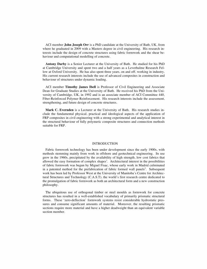
Figure 1 — Fabric formed concrete structures
Forming concrete in a permeable fabric mould has two fundamental consequences. By allowing air and water to escape from the mould, moderate reductions in water:cement ratio are seen, which in turn bring small increases in compressive strength. More import-antly, the external concrete surface is now generally free of voids, reducing the ingress of air and water into the section and improving durability. In turn, this can reduce cover re-quirements for the internal reinforcement and provides a high quality surface finish to the structure.
Whilst architectural interest in this field is growing, the advantages of fabric formwork are yet to be fully realised by the construction industry. This paper presents new test data to illustrate the use of both advanced composites and steel as internal reinforcement in fabric formed structures. An innovative anchorage method, used here in beam tests for the first time, is also assessed before the potential future development of fabric formwork technology is discussed.
RESEARCH SIGNIFICANCE
Concrete has relatively low embodied energy but is used in vast quantities: in 2008 world production of cement was approximately 2.8x10⁹ metric tons3 (2.8x10¹² kg) and its manufacture accounted for almost 3% of global CO2 emissions4, suggesting that concrete should be cast in optimised structures. Fabric formwork at last provides a suitable method to achieve these reductions by facilitating the production of variable section members (Figure 1). Concrete volume savings of up to 40%5, 6 are feasible and the use of fibre-reinforced polymers as either internal or external reinforcement presents exciting new opportunities for the practical use of fabric formwork.
DESIGN
Structural design procedures for bending moment shaped beams, as developed at the University of Bath5, 6, are based on a sectional approach that aims to satisfy the bending and shear requirements of the beam at every point along its length, as summarised in Fig-ure 2. The final shape of the fabric formed beam is determined by a combination of the fabric’s material properties and the boundary conditions imposed on it during construc-tion. Accurate shape predictions of the fluid filled fabric are therefore required, from which the construction boundary conditions are determined.
!"#$%&'
()&
*#'
'+*##'
,*)
%'
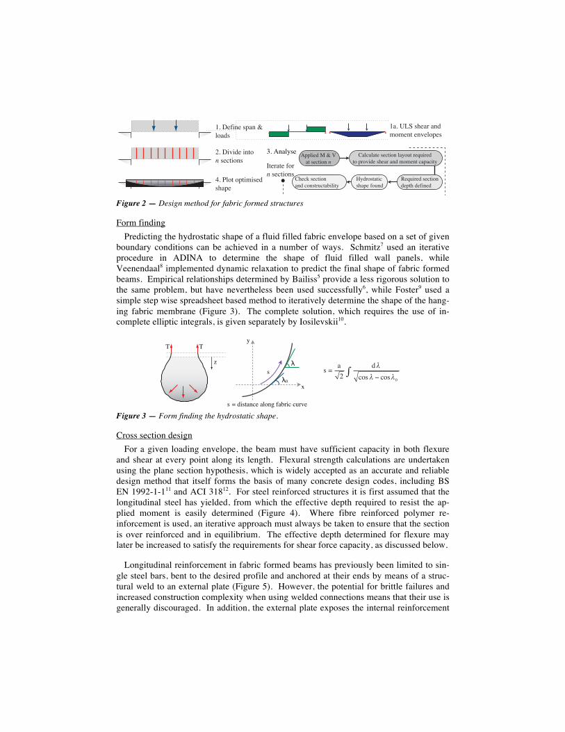
Figure 2 — Design method for fabric formed structures
Form finding Predicting the hydrostatic shape of a fluid filled fabric envelope based on a set of given
boundary conditions can be achieved in a number of ways. Schmitz7 used an iterative procedure in ADINA to determine the shape of fluid filled wall panels, while Veenendaal8 implemented dynamic relaxation to predict the final shape of fabric formed beams. Empirical relationships determined by Bailiss5 provide a less rigorous solution to the same problem, but have nevertheless been used successfully6, while Foster9 used a simple step wise spreadsheet based method to iteratively determine the shape of the hang-ing fabric membrane (Figure 3). The complete solution, which requires the use of in-complete elliptic integrals, is given separately by Iosilevskii10.
Figure 3 — Form finding the hydrostatic shape.
Cross section design For a given loading envelope, the beam must have sufficient capacity in both flexure
and shear at every point along its length. Flexural strength calculations are undertaken using the plane section hypothesis, which is widely accepted as an accurate and reliable design method that itself forms the basis of many concrete design codes, including BS EN 1992-1-111 and ACI 31812. For steel reinforced structures it is first assumed that the longitudinal steel has yielded, from which the effective depth required to resist the ap-plied moment is easily determined (Figure 4). Where fibre reinforced polymer re-inforcement is used, an iterative approach must always be taken to ensure that the section is over reinforced and in equilibrium. The effective depth determined for flexure may later be increased to satisfy the requirements for shear force capacity, as discussed below.
Longitudinal reinforcement in fabric formed beams has previously been limited to sin-gle steel bars, bent to the desired profile and anchored at their ends by means of a struc-tural weld to an external plate (Figure 5). However, the potential for brittle failures and increased construction complexity when using welded connections means that their use is generally discouraged. In addition, the external plate exposes the internal reinforcement
!"#$%&'$()*"+$",-$./.*,0$*,1*2/3*(
4#$5616-*$6,0/$!$(*706/,(
8#$9,"2:(* 93326*-$;$<$="0$(*706/,$!
>*?@6+*-$(*706/,$-*30)$-*A6,*-
B:-+/(0"067$()"3*$A/@,-
C#$D2/0$/306.6(*-$()"3*
E"27@2"0*$(*706/,$2":/@0$+*?@6+*-0/$3+/16-*$()*"+$",-$./.*,0$7"3"760:F0*+"0*$A/+$
!$(*706/,(E)*7G$(*706/,",-$7/,(0+@70"H6260:
!#$5*A6,*$(3",$<2/"-(
!
"
!#
$%
&
&'(')*&+,-./',01-2'3,45*.'.657/
& , )(8 %.1& .1&
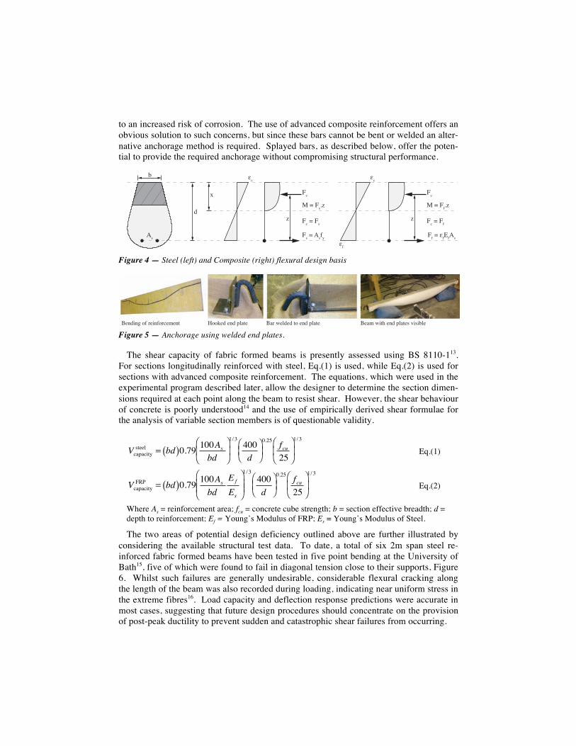
to an increased risk of corrosion. The use of advanced composite reinforcement offers an obvious solution to such concerns, but since these bars cannot be bent or welded an alter-native anchorage method is required. Splayed bars, as described below, offer the poten-tial to provide the required anchorage without compromising structural performance.
Figure 4 — Steel (left) and Composite (right) flexural design basis
Figure 5 — Anchorage using welded end plates.
The shear capacity of fabric formed beams is presently assessed using BS 8110-113. For sections longitudinally reinforced with steel, Eq.(1) is used, while Eq.(2) is used for sections with advanced composite reinforcement. The equations, which were used in the experimental program described later, allow the designer to determine the section dimen-sions required at each point along the beam to resist shear. However, the shear behaviour of concrete is poorly understood14 and the use of empirically derived shear formulae for the analysis of variable section members is of questionable validity.
�
Vcapacitysteel = bd( )0.79 100As
bd⎛
⎝ ⎜
⎞
⎠ ⎟ 1/ 3
400d
⎛ ⎝ ⎜
⎞ ⎠ ⎟ 0.25 fcu
25⎛
⎝ ⎜
⎞
⎠ ⎟ 1/ 3
Eq.(1)
�
VcapacityFRP = bd( )0.79 100As
bdE f
Es
⎛
⎝ ⎜ ⎜
⎞
⎠ ⎟ ⎟
1/ 3400d
⎛ ⎝ ⎜
⎞ ⎠ ⎟ 0.25 fcu
25⎛
⎝ ⎜
⎞
⎠ ⎟ 1/ 3
Eq.(2)
Where As = reinforcement area; fcu = concrete cube strength; b = section effective breadth; d = depth to reinforcement; Ef = Young’s Modulus of FRP; Es = Young’s Modulus of Steel.
The two areas of potential design deficiency outlined above are further illustrated by considering the available structural test data. To date, a total of six 2m span steel re-inforced fabric formed beams have been tested in five point bending at the University of Bath15, five of which were found to fail in diagonal tension close to their supports, Figure 6. Whilst such failures are generally undesirable, considerable flexural cracking along the length of the beam was also recorded during loading, indicating near uniform stress in the extreme fibres16. Load capacity and deflection response predictions were accurate in most cases, suggesting that future design procedures should concentrate on the provision of post-peak ductility to prevent sudden and catastrophic shear failures from occurring.
!
"
#
$%
&
'(
'%)*)$%+,
-)*)'%.&
'()*)'%)
() (
+
&
'(
'+ +/+$%
-)*)'+.&
'()*)'+)
!"#$%#&'()'*"%#)(*+","#- .((/"$'"#$'012-" !2*'3"1$"$'-('"#$'012-" !"2,'3%-4'"#$'012-"5'6%5%71"
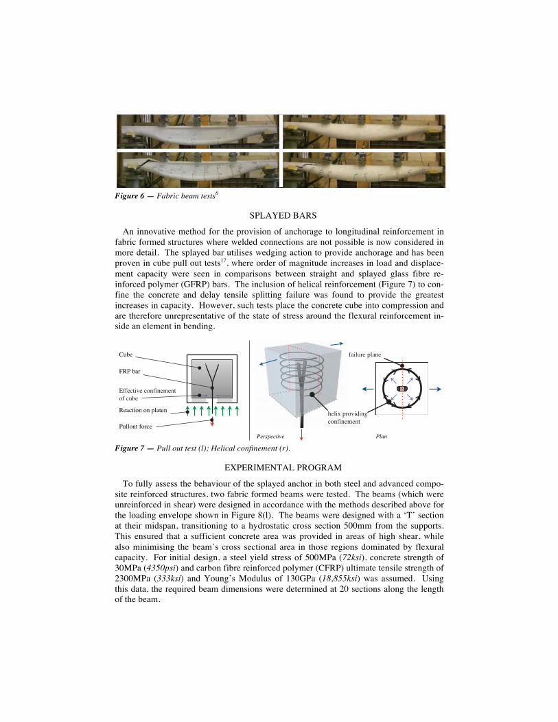
Figure 6 — Fabric beam tests6
SPLAYED BARS
An innovative method for the provision of anchorage to longitudinal reinforcement in fabric formed structures where welded connections are not possible is now considered in more detail. The splayed bar utilises wedging action to provide anchorage and has been proven in cube pull out tests17, where order of magnitude increases in load and displace-ment capacity were seen in comparisons between straight and splayed glass fibre re-inforced polymer (GFRP) bars. The inclusion of helical reinforcement (Figure 7) to con-fine the concrete and delay tensile splitting failure was found to provide the greatest increases in capacity. However, such tests place the concrete cube into compression and are therefore unrepresentative of the state of stress around the flexural reinforcement in-side an element in bending.
Figure 7 — Pull out test (l); Helical confinement (r).
EXPERIMENTAL PROGRAM
To fully assess the behaviour of the splayed anchor in both steel and advanced compo-site reinforced structures, two fabric formed beams were tested. The beams (which were unreinforced in shear) were designed in accordance with the methods described above for the loading envelope shown in Figure 8(l). The beams were designed with a ‘T’ section at their midspan, transitioning to a hydrostatic cross section 500mm from the supports. This ensured that a sufficient concrete area was provided in areas of high shear, while also minimising the beam’s cross sectional area in those regions dominated by flexural capacity. For initial design, a steel yield stress of 500MPa (72ksi), concrete strength of 30MPa (4350psi) and carbon fibre reinforced polymer (CFRP) ultimate tensile strength of 2300MPa (333ksi) and Young’s Modulus of 130GPa (18,855ksi) was assumed. Using this data, the required beam dimensions were determined at 20 sections along the length of the beam.
!"##$"%&'$()*
+*,)%-$.&$.&/#,%*.
0"1*
2+!&1,(
!"#$%"&'()" !*+,
',-#"(*&/#,.*
3*#-4&/($5-6-.7)$.'-.*8*.%
9''*)%-5*&)$.'-.*8*.%$'&)"1*
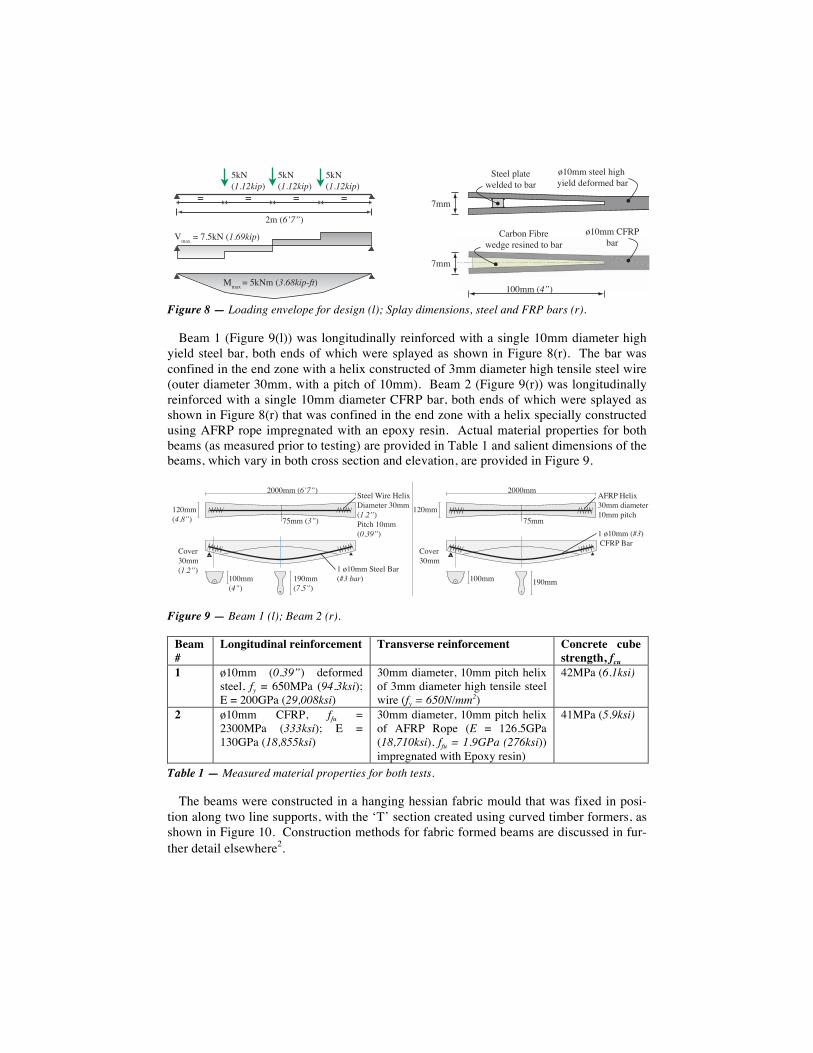
Figure 8 — Loading envelope for design (l); Splay dimensions, steel and FRP bars (r).
Beam 1 (Figure 9(l)) was longitudinally reinforced with a single 10mm diameter high yield steel bar, both ends of which were splayed as shown in Figure 8(r). The bar was confined in the end zone with a helix constructed of 3mm diameter high tensile steel wire (outer diameter 30mm, with a pitch of 10mm). Beam 2 (Figure 9(r)) was longitudinally reinforced with a single 10mm diameter CFRP bar, both ends of which were splayed as shown in Figure 8(r) that was confined in the end zone with a helix specially constructed using AFRP rope impregnated with an epoxy resin. Actual material properties for both beams (as measured prior to testing) are provided in Table 1 and salient dimensions of the beams, which vary in both cross section and elevation, are provided in Figure 9.
Figure 9 — Beam 1 (l); Beam 2 (r).
Beam #
Longitudinal reinforcement Transverse reinforcement Concrete cube strength, fcu
1 ø10mm (0.39”) deformed steel, fy = 650MPa (94.3ksi); E = 200GPa (29,008ksi)
30mm diameter, 10mm pitch helix of 3mm diameter high tensile steel wire (fy = 650N/mm2)
42MPa (6.1ksi)
2 ø10mm CFRP, ffu = 2300MPa (333ksi); E = 130GPa (18,855ksi)
30mm diameter, 10mm pitch helix of AFRP Rope (E = 126.5GPa (18,710ksi), ffu = 1.9GPa (276ksi)) impregnated with Epoxy resin)
41MPa (5.9ksi)
Table 1 — Measured material properties for both tests.
The beams were constructed in a hanging hessian fabric mould that was fixed in posi-tion along two line supports, with the ‘T’ section created using curved timber formers, as shown in Figure 10. Construction methods for fabric formed beams are discussed in fur-ther detail elsewhere2.
!""
#$%""&'())*&+,-+&.,)*/&/)012")/&342
5 5 5 5
6789!"!#$%&:
6789!"!#$%&:
6789!"!#$%&:
;"&9'()*:
<"4=&5&678"&9+"',$%&-./:&
>"4=&5&!?678&9!"'0$%&:
$%%""&91*:
!""
@())*&A*4()B)*/)/&(1&342
#$%""&CDEF342
C4231G&D,32)&B)/-)&2)',G)/&(1&342&
!"""##$%!"#$&
'!"##%%&'$& ()##$%($&
'$*'"##$+,--.$/01%)(*+,-&
+,--.$231-$4-.35630#-,-1$7"##$%.&/$&83,9:$'"##%0&(1$&
;<=-17"##%.&/$&
'""##%%$&
'>"##%#&2$&
'$*'"##$%)(&$;?@8$/01
!"""##
'!"##()##
A?@8$4-.357"##$B30#-,-1'"##$C3,9:
;<=-17"##
'""## '>"##
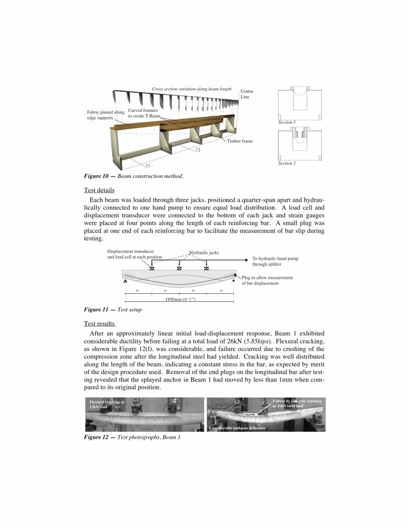
Figure 10 — Beam construction method.
Test details Each beam was loaded through three jacks, positioned a quarter-span apart and hydrau-
lically connected to one hand pump to ensure equal load distribution. A load cell and displacement transducer were connected to the bottom of each jack and strain gauges were placed at four points along the length of each reinforcing bar. A small plug was placed at one end of each reinforcing bar to facilitate the measurement of bar slip during testing.
Figure 11 — Test setup
Test results After an approximately linear initial load-displacement response, Beam 1 exhibited
considerable ductility before failing at a total load of 26kN (5.85kips). Flexural cracking, as shown in Figure 12(l), was considerable, and failure occurred due to crushing of the compression zone after the longitudinal steel had yielded. Cracking was well distributed along the length of the beam, indicating a constant stress in the bar, as expected by merit of the design procedure used. Removal of the end plugs on the longitudinal bar after test-ing revealed that the splayed anchor in Beam 1 had moved by less than 1mm when com-pared to its original position.
Figure 12 — Test photographs, Beam 1
!"#$%"&'(#"
)(*+"%&,%-*"
.-+%(/&0(##"1&-23#4"14"&56003%$5
!"#$$%$&'()#*%+,"),()#*%,-#*.%/&,0%-&*.(1
!6%7"1&,3%*"%5$3&/%"-$"&)89"-*
2&'()#*%3
2&'()#*%4:
;
!"#$%%&'!"#$%(
)*&+,-./0123&+/4-&50%56+.*07+&8512669.
:2851/39%946&6./48-039./4-&1*/-&3911&/6&9/3+&5*8262*4
; ; ;;
<,-./0123&=/3>8
?107&6*&/11*@&%9/80.9%946*A&B/.&-2851/39%946&
!"#$%&'"()&')*+,-('./0*1("2'3
!'+"%&#(45()2,)&#.#()&%67+,-'.(08*1(.2.'"("2'3
92,6+3#&'4"#(:+36;',(3#<"#).+2,
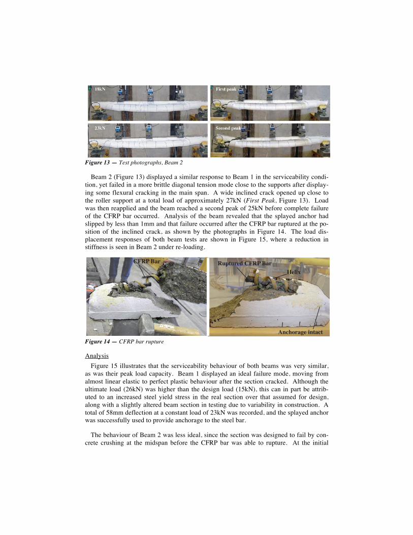
Figure 13 — Test photographs, Beam 2
Beam 2 (Figure 13) displayed a similar response to Beam 1 in the serviceability condi-tion, yet failed in a more brittle diagonal tension mode close to the supports after display-ing some flexural cracking in the main span. A wide inclined crack opened up close to the roller support at a total load of approximately 27kN (First Peak, Figure 13). Load was then reapplied and the beam reached a second peak of 25kN before complete failure of the CFRP bar occurred. Analysis of the beam revealed that the splayed anchor had slipped by less than 1mm and that failure occurred after the CFRP bar ruptured at the po-sition of the inclined crack, as shown by the photographs in Figure 14. The load dis-placement responses of both beam tests are shown in Figure 15, where a reduction in stiffness is seen in Beam 2 under re-loading.
Figure 14 — CFRP bar rupture
Analysis Figure 15 illustrates that the serviceability behaviour of both beams was very similar,
as was their peak load capacity. Beam 1 displayed an ideal failure mode, moving from almost linear elastic to perfect plastic behaviour after the section cracked. Although the ultimate load (26kN) was higher than the design load (15kN), this can in part be attrib-uted to an increased steel yield stress in the real section over that assumed for design, along with a slightly altered beam section in testing due to variability in construction. A total of 58mm deflection at a constant load of 23kN was recorded, and the splayed anchor was successfully used to provide anchorage to the steel bar.
The behaviour of Beam 2 was less ideal, since the section was designed to fail by con-crete crushing at the midspan before the CFRP bar was able to rupture. At the initial
!"#$%&'()'*"+,-.&/,01*
23456*17",$3)14)
-.&/,01*
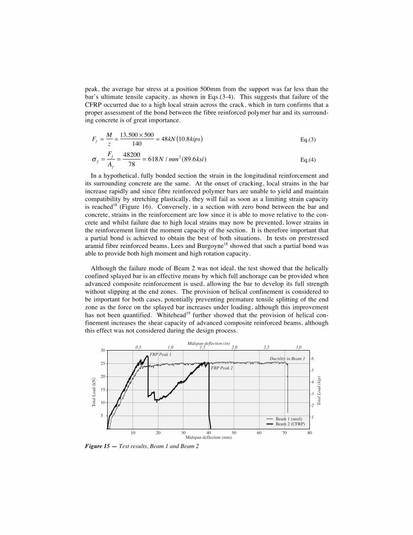
peak, the average bar stress at a position 500mm from the support was far less than the bar’s ultimate tensile capacity, as shown in Eqs.(3-4). This suggests that failure of the CFRP occurred due to a high local strain across the crack, which in turn confirms that a proper assessment of the bond between the fibre reinforced polymer bar and its surround-ing concrete is of great importance.
Ff =Mz
= 13, 500 × 500140
= 48kN 10.8kips( ) Eq.(3)
σ f =FfAf
= 4820078
= 618N / mm2 (89.6ksi) Eq.(4)
In a hypothetical, fully bonded section the strain in the longitudinal reinforcement and its surrounding concrete are the same. At the onset of cracking, local strains in the bar increase rapidly and since fibre reinforced polymer bars are unable to yield and maintain compatibility by stretching plastically, they will fail as soon as a limiting strain capacity is reached18 (Figure 16). Conversely, in a section with zero bond between the bar and concrete, strains in the reinforcement are low since it is able to move relative to the con-crete and whilst failure due to high local strains may now be prevented, lower strains in the reinforcement limit the moment capacity of the section. It is therefore important that a partial bond is achieved to obtain the best of both situations. In tests on prestressed aramid fibre reinforced beams, Lees and Burgoyne18 showed that such a partial bond was able to provide both high moment and high rotation capacity.
Although the failure mode of Beam 2 was not ideal, the test showed that the helically confined splayed bar is an effective means by which full anchorage can be provided when advanced composite reinforcement is used, allowing the bar to develop its full strength without slipping at the end zones. The provision of helical confinement is considered to be important for both cases, potentially preventing premature tensile splitting of the end zone as the force on the splayed bar increases under loading, although this improvement has not been quantified. Whitehead19 further showed that the provision of helical con-finement increases the shear capacity of advanced composite reinforced beams, although this effect was not considered during the design process.
Figure 15 — Test results, Beam 1 and Beam 2
!"
#$
#"
%$
%"
$
%" #" !" &" $" '" (" )"
*+,-./0+-1/2345
67-8/%/29,77.567-8/#/2:;<=5
>?19@-A/17B.7C,?+A/2885
!"#$%&'"$(&)*+,-
.+(/,$0&(12%13#+"0&)+0-456 754 756 854 856 954
7
8
9
:
6
;<=>&>1$*&7
<=>&>1$*&8
?@3#+%+#A&+0&B1$C&7
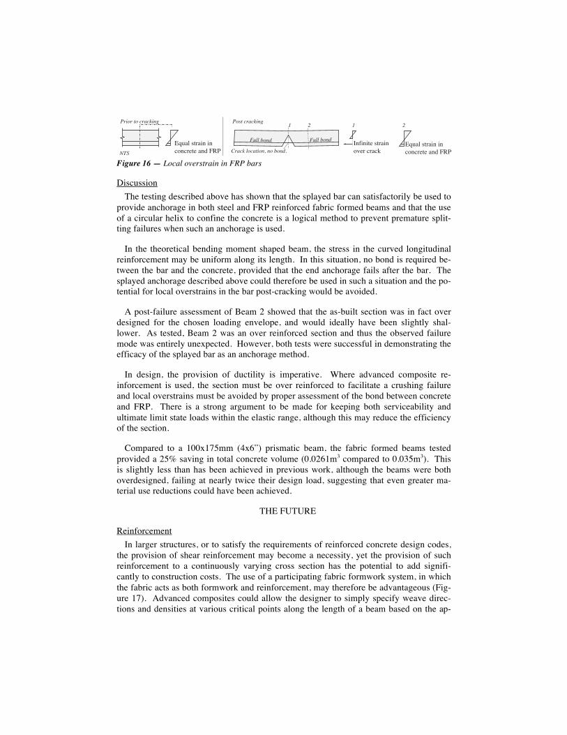
Figure 16 — Local overstrain in FRP bars
Discussion The testing described above has shown that the splayed bar can satisfactorily be used to
provide anchorage in both steel and FRP reinforced fabric formed beams and that the use of a circular helix to confine the concrete is a logical method to prevent premature split-ting failures when such an anchorage is used.
In the theoretical bending moment shaped beam, the stress in the curved longitudinal reinforcement may be uniform along its length. In this situation, no bond is required be-tween the bar and the concrete, provided that the end anchorage fails after the bar. The splayed anchorage described above could therefore be used in such a situation and the po-tential for local overstrains in the bar post-cracking would be avoided.
A post-failure assessment of Beam 2 showed that the as-built section was in fact over designed for the chosen loading envelope, and would ideally have been slightly shal-lower. As tested, Beam 2 was an over reinforced section and thus the observed failure mode was entirely unexpected. However, both tests were successful in demonstrating the efficacy of the splayed bar as an anchorage method.
In design, the provision of ductility is imperative. Where advanced composite re-inforcement is used, the section must be over reinforced to facilitate a crushing failure and local overstrains must be avoided by proper assessment of the bond between concrete and FRP. There is a strong argument to be made for keeping both serviceability and ultimate limit state loads within the elastic range, although this may reduce the efficiency of the section.
Compared to a 100x175mm (4x6”) prismatic beam, the fabric formed beams tested provided a 25% saving in total concrete volume (0.0261m3 compared to 0.035m3). This is slightly less than has been achieved in previous work, although the beams were both overdesigned, failing at nearly twice their design load, suggesting that even greater ma-terial use reductions could have been achieved.
THE FUTURE
Reinforcement In larger structures, or to satisfy the requirements of reinforced concrete design codes,
the provision of shear reinforcement may become a necessity, yet the provision of such reinforcement to a continuously varying cross section has the potential to add signifi-cantly to construction costs. The use of a participating fabric formwork system, in which the fabric acts as both formwork and reinforcement, may therefore be advantageous (Fig-ure 17). Advanced composites could allow the designer to simply specify weave direc-tions and densities at various critical points along the length of a beam based on the ap-
!"#$%&'()$*+&*+&,-+,).(.&$+/&012
3+4*+*(.&'()$*+&-5.)&,)$,6&
! " ! "#$%&$'(&')$*)+%,- #&.(')$*)+%,-
/$*)+'0&)*(%&,1',&'2&,34
5600'2&,3 5600'2&,3!"#$%&'()$*+&*+&,-+,).(.&$+/&012789
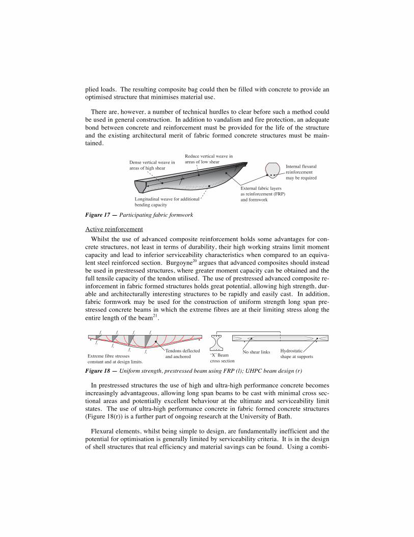
plied loads. The resulting composite bag could then be filled with concrete to provide an optimised structure that minimises material use.
There are, however, a number of technical hurdles to clear before such a method could be used in general construction. In addition to vandalism and fire protection, an adequate bond between concrete and reinforcement must be provided for the life of the structure and the existing architectural merit of fabric formed concrete structures must be main-tained.
Figure 17 — Participating fabric formwork
Active reinforcement Whilst the use of advanced composite reinforcement holds some advantages for con-
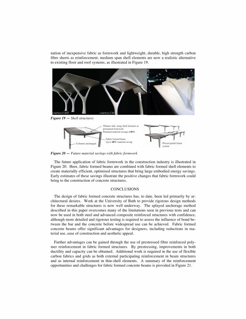
crete structures, not least in terms of durability, their high working strains limit moment capacity and lead to inferior serviceability characteristics when compared to an equiva-lent steel reinforced section. Burgoyne20 argues that advanced composites should instead be used in prestressed structures, where greater moment capacity can be obtained and the full tensile capacity of the tendon utilised. The use of prestressed advanced composite re-inforcement in fabric formed structures holds great potential, allowing high strength, dur-able and architecturally interesting structures to be rapidly and easily cast. In addition, fabric formwork may be used for the construction of uniform strength long span pre-stressed concrete beams in which the extreme fibres are at their limiting stress along the entire length of the beam21.
Figure 18 — Uniform strength, prestressed beam using FRP (l); UHPC beam design (r)
In prestressed structures the use of high and ultra-high performance concrete becomes increasingly advantageous, allowing long span beams to be cast with minimal cross sec-tional areas and potentially excellent behaviour at the ultimate and serviceability limit states. The use of ultra-high performance concrete in fabric formed concrete structures (Figure 18(r)) is a further part of ongoing research at the University of Bath.
Flexural elements, whilst being simple to design, are fundamentally inefficient and the potential for optimisation is generally limited by serviceability criteria. It is in the design of shell structures that real efficiency and material savings can be found. Using a combi-
!"#$"%&"'()*+,%-"+&"%)#%+'"+$%./%0)10%$0"+'
2"34*"%&"'()*+,%-"+&"%)#%+'"+$%./%,.-%$0"+'
5.#1)(43)#+,%-"+&"%/.'%+33)().#+,%6"#3)#1%*+7+*)(8
9:("'#+,%/+6')*%,+8"'$+$%'")#/.'*";"#(%<=2>?+#3%/.';-.'@
A#("'#+,%/,":4'+,'")#/.'*";"#(;+8%6"%'"B4)'"3
!"#$%#&'$"()"*+"$',#$',#*-%."$
!" !" !" !"
!# !# !# !#/0+."1"'(23."'&+."&&"&'*%#&+,#+',#$',+'$"&24#')212+&5
678'9",1'*.%&&'&"*+2%#
:;$.%&+,+2*'&-,<"',+'&=<<%.+&
>%'&-",.')2#?&
nation of inexpensive fabric as formwork and lightweight, durable, high strength carbon fibre sheets as reinforcement, medium span shell elements are now a realistic alternative to existing floor and roof systems, as illustrated in Figure 19.
Figure 19 — Shell structures
Figure 20 — Future material savings with fabric formwork
The future application of fabric formwork in the construction industry is illustrated in Figure 20. Here, fabric formed beams are combined with fabric formed shell elements to create materially efficient, optimised structures that bring large embodied energy savings. Early estimates of these savings illustrate the positive changes that fabric formwork could bring to the construction of concrete structures.
CONCLUSIONS
The design of fabric formed concrete structures has, to date, been led primarily by ar-chitectural desires. Work at the University of Bath to provide rigorous design methods for these remarkable structures is now well underway. The splayed anchorage method described in this paper overcomes many of the limitations seen in previous tests and can now be used in both steel and advanced composite reinforced structures with confidence, although more detailed and rigorous testing is required to assess the influence of bond be-tween the bar and the concrete before widespread use can be achieved. Fabric formed concrete beams offer significant advantages for designers, including reductions in ma-terial use, ease of construction and aesthetic appeal.
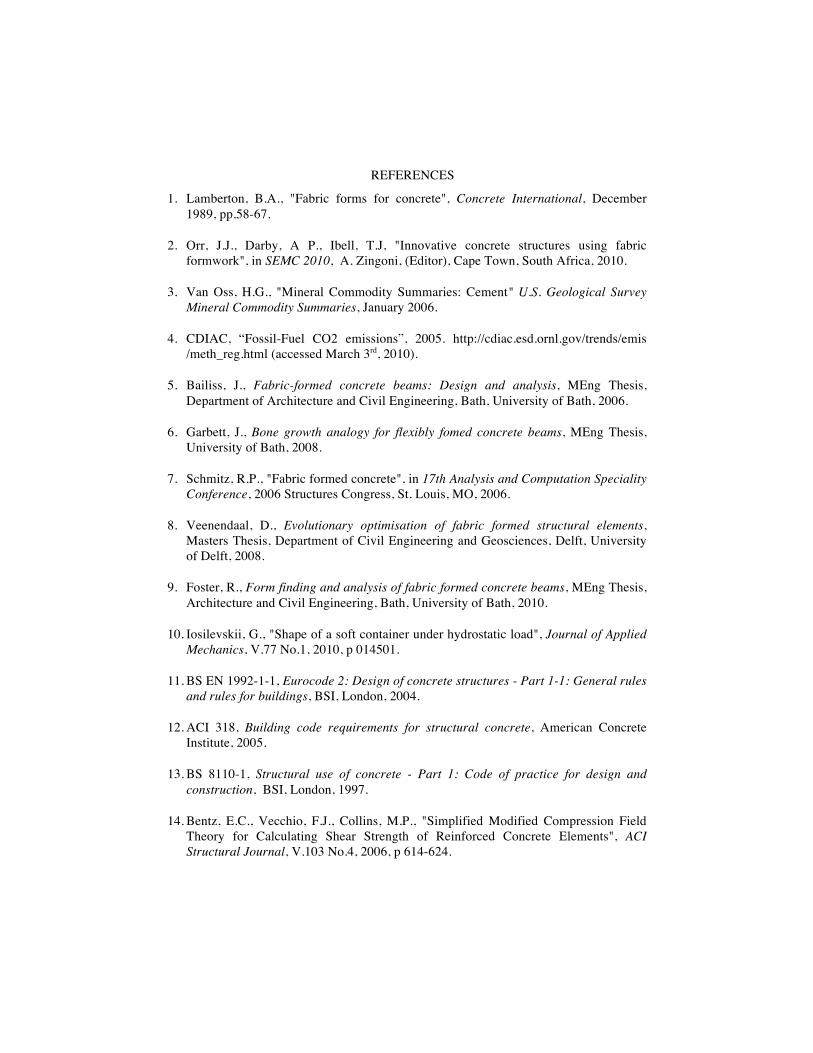
Further advantages can be gained through the use of prestressed fibre reinforced poly-mer reinforcement in fabric formed structures. By prestressing, improvements in both ductility and capacity can be obtained. Additional work is required in the use of flexible carbon fabrics and grids as both external participating reinforcement in beam structures and as internal reinforcement in thin-shell elements. A summary of the reinforcement opportunities and challenges for fabric formed concrete beams is provided in Figure 21.
!"#$%&'()*+,- !"#$%&'()*+,-
!"#$%&'()$*+,'#+"*-.'/)'!"#'*"/+$%"0'1"2%345)06*31'63&7"34+,
87%33+$'10"#9'61%34'17+00'+0+*+3/1'"1'.+$*"3+3/'()$*:)$;<)/+3/%"0'*"/+$%"0'1"2%341'$%"#
<$+&"1/'.)$/"0'($"*+1=1/+*
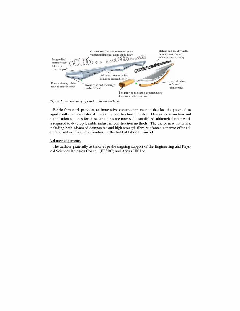
Figure 21 — Summary of reinforcement methods.
Fabric formwork provides an innovative construction method that has the potential to significantly reduce material use in the construction industry. Design, construction and optimisation routines for these structures are now well established, although further work is required to develop feasible industrial construction methods. The use of new materials, including both advanced composites and high strength fibre reinforced concrete offer ad-ditional and exciting opportunities for the field of fabric formwork.
Acknowledgements The authors gratefully acknowledge the ongoing support of the Engineering and Phys-
ical Sciences Research Council (EPSRC) and Atkins UK Ltd.
!"#$%&$'(#$)*+,'-)$.%&-.&,-&($/#-0&1&$',2,3(//&-&$',*($4,.(5&.,)*#$6,&$'(-&,7&)1
8#$6('93($)*,-&($/#-0&1&$',/#**#:.,),0#1;*&<,;-#/(*&
=#..(7(*('>,'#,9.&,/)7-(0,).,;)-'(0(;)'($6,/#-1:#-4,($,'?&,.?&)-,5#$&
@<'&-$)*,/)7-(0).,/*&<9-)*,-&($/#-0&1&$'
A&*(0&.,)33,390'(*('>,($,'?&,0#1;-&..(#$,5#$&,)$3,&$?)$0&,.?&)-,0);)0('>
=-#%(.(#$,#/,&$3,)$0?#-)6&,0)$,7&,3(//(09*'
=#.'B'&$.(#$($6,0)7*&.,1)>,7&,1#-&,.9(')7*&
C3%)$0&3,0#1;#.('&,7)-.-&D9(-($6,-&390&3,0#%&-
REFERENCES
1. Lamberton, B.A., "Fabric forms for concrete", Concrete International, December 1989, pp.58-67.
2. Orr, J.J., Darby, A P., Ibell, T.J, "Innovative concrete structures using fabric formwork", in SEMC 2010, A. Zingoni, (Editor), Cape Town, South Africa, 2010.
3. Van Oss, H.G., "Mineral Commodity Summaries: Cement" U.S. Geological Survey Mineral Commodity Summaries, January 2006.
4. CDIAC, “Fossil-Fuel CO2 emissions”, 2005. http://cdiac.esd.ornl.gov/trends/emis /meth_reg.html (accessed March 3rd, 2010).
5. Bailiss, J., Fabric-formed concrete beams: Design and analysis, MEng Thesis, Department of Architecture and Civil Engineering, Bath, University of Bath, 2006.
6. Garbett, J., Bone growth analogy for flexibly fomed concrete beams, MEng Thesis, University of Bath, 2008.
7. Schmitz, R.P., "Fabric formed concrete", in 17th Analysis and Computation Speciality Conference, 2006 Structures Congress, St. Louis, MO, 2006.
8. Veenendaal, D., Evolutionary optimisation of fabric formed structural elements, Masters Thesis, Department of Civil Engineering and Geosciences, Delft, University of Delft, 2008.
9. Foster, R., Form finding and analysis of fabric formed concrete beams, MEng Thesis, Architecture and Civil Engineering, Bath, University of Bath, 2010.
10. Iosilevskii, G., "Shape of a soft container under hydrostatic load", Journal of Applied Mechanics, V.77 No.1, 2010, p 014501.
11. BS EN 1992-1-1, Eurocode 2: Design of concrete structures - Part 1-1: General rules and rules for buildings, BSI, London, 2004.
12. ACI 318, Building code requirements for structural concrete, American Concrete Institute, 2005.
13. BS 8110-1, Structural use of concrete - Part 1: Code of practice for design and construction, BSI, London, 1997.
14. Bentz, E.C., Vecchio, F.J., Collins, M.P., "Simplified Modified Compression Field Theory for Calculating Shear Strength of Reinforced Concrete Elements", ACI Structural Journal, V.103 No.4, 2006, p 614-624.
15. Ibell, T.J., Darby, A.P., Bailiss, J.A., "Fabric formed concrete beams", in ACIC 2007, A.P. Darby, Editor, University of Bath, Bath, 2007.
16. Ibell, T.J., Darby, A., Denton, S., "Fabric formwork for innovative concrete structures", in FRPRCS-9, Sydney, 2009.
17. Darby, A.D., Ibell, T.J., Tallis, S., & Winkle, C., "End Anchorage for Internal FRP reinforcement", in FRPRCS-8, T.C. Triantafillou, Editor, University of Patras, Greece, 2007.
18. Lees, J.M., Burgoyne, C B, "Experimental Study of Influence of Bond on Flexural Behavior of Concrete Beams Pretensioned with Aramid Fiber Reinforced Plastics", ACI Structural Journal, V.96 No.3, 1999, p 377-386.
19. Whitehead, P., Ibell, T.J., "Novel shear reinforcement for fibre reinforced polymer reinforced and prestressed concrete", ACI Structural Journal, V.102 No.2, 2005, p 286-294.
20. Burgoyne, C.J., "Rational Use of Advanced Composites in Concrete", Proc. ICE Structures & Buildings, V.146, 2001, p 253-262.
21. Guyon, Y., Prestressed Concrete. London, Contractors Record and Municipal Engineering, 1953.