Embed Size (px)
Citation preview
INNOVATIVE PILE EXTRACTION TECHNIQUE OF CFA PILES FOR THE NEW HARBOR BRIDGE PROJECT
Tracy Brettmann, P.E., D.GE, Vice President, A. H. Beck Foundation Company, Houston, Texas, (713) 413-3800, [email protected]
ABSTRACT
The nearly $900 million US 181 Harbor Bridge Project in Corpus Christi, Texas will include the development, design and construction of 10 km of combined bridge and roadway. It will include the new six-lane Harbor Bridge as well as the reconstruction of adjoining sections of two freeways. This will be the longest cable stay bridge in the United States when completed. Once the new bridge is open to the traveling public, the project will conclude with the demolition of the existing Harbor Bridge. The main towers of the bridge will be 164 m (538 ft) tall and are supported on a group of large diameter drilled shafts. Each tower is supported on twenty two 3 m (10 ft) diameter by 75 m (250 ft) deep shafts. The north tower is located where a previous industrial warehouse was sited. This warehouse was supported on closely spaced 400 mm (16 in) nominal diameter by 20 m (65 ft) long CFA piles, which required the removal of these piles where they conflicted with the new drilled shafts. The amount of steel reinforcing in the piles required that they be extracted in one piece. The actual diameter of the piles was also expected to vary significantly due to the soft layered soil conditions encountered in the upper 15 m (50 ft). An innovative wet rotary coring technique involving the combined use of both hanging lead CFA drilling equipment and a drilled shaft bentonite slurry drilling system was used to rapidly extract the large quantity of conflicting piles.
INTRODUCTION
The Harbor Bridge Project (HBP) currently under construction in Corpus Christi, Texas will replace the existing adjacent steel arch bridge. The Texas Department of Transportation (TxDOT) has determined that US 181 and the Harbor Bridge must be improved to maintain a safe and efficient transportation corridor. The existing bridge has safety issues associated with the lack of shoulders, steep grade, a reverse curve, and an accident rate that is higher than the statewide average. The current Harbor Bridge also has high maintenance costs and provides no acceptable access for those on foot or on bicycles. Furthermore, the bridge’s 42 m (138 ft) of navigational clearance, which met World War II standards when it was built, makes it difficult for the Port of Corpus Christi to compete with other Gulf Coast deep water ports because of larger ship sizes today.
The new bridge will allow TxDOT to improve safety, thereby reducing accident rates; provide better opportunities for moving people and goods throughout the region; provide adequate capacity to meet future traffic demand; and provide greater economic development opportunities for the Port of Corpus Christi.
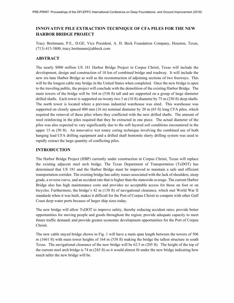
The new cable stayed bridge shown in Fig. 1 will have a main span length between the towers of 506 m (1661 ft) with main tower heights of 164 m (538 ft) making the bridge the tallest structure in south Texas. The navigational clearance of the new bridge will be 62.5 m (205 ft). The height of the top of the current steel arch bridge is 74 m (243 ft) so it would almost fit under the new bridge indicating how much taller the new bridge will be.
PRE-PRINT: Proceedings of the DFI-EFFC International Conference on Deep Foundations and Ground Improvement (2018)
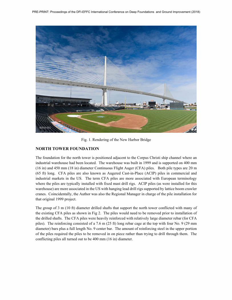
Fig. 1. Rendering of the New Harbor Bridge
NORTH TOWER FOUNDATION
The foundation for the north tower is positioned adjacent to the Corpus Christi ship channel where an industrial warehouse had been located. The warehouse was built in 1999 and is supported on 400 mm (16 in) and 450 mm (18 in) diameter Continuous Flight Auger (CFA) piles. Both pile types are 20 m (65 ft) long. CFA piles are also known as Augered Cast-in-Place (ACIP) piles in commercial and industrial markets in the US. The term CFA piles are more associated with European terminology where the piles are typically installed with fixed mast drill rigs. ACIP piles (as were installed for this warehouse) are more associated in the US with hanging lead drill rigs supported by lattice boom crawler cranes. Coincidentally, the Author was also the Regional Manager in charge of the pile installation for that original 1999 project.
The group of 3 m (10 ft) diameter drilled shafts that support the north tower conflicted with many of the existing CFA piles as shown in Fig 2. The piles would need to be removed prior to installation of the drilled shafts. The CFA piles were heavily reinforced with relatively large diameter rebar (for CFA piles). The reinforcing consisted of a 7.6 m (25 ft) long rebar cage at the top with four No. 9 (29 mm diameter) bars plus a full length No. 9 center bar. The amount of reinforcing steel in the upper portion of the piles required the piles to be removed in on piece rather than trying to drill through them. The conflicting piles all turned out to be 400 mm (16 in) diameter.
PRE-PRINT: Proceedings of the DFI-EFFC International Conference on Deep Foundations and Ground Improvement (2018)
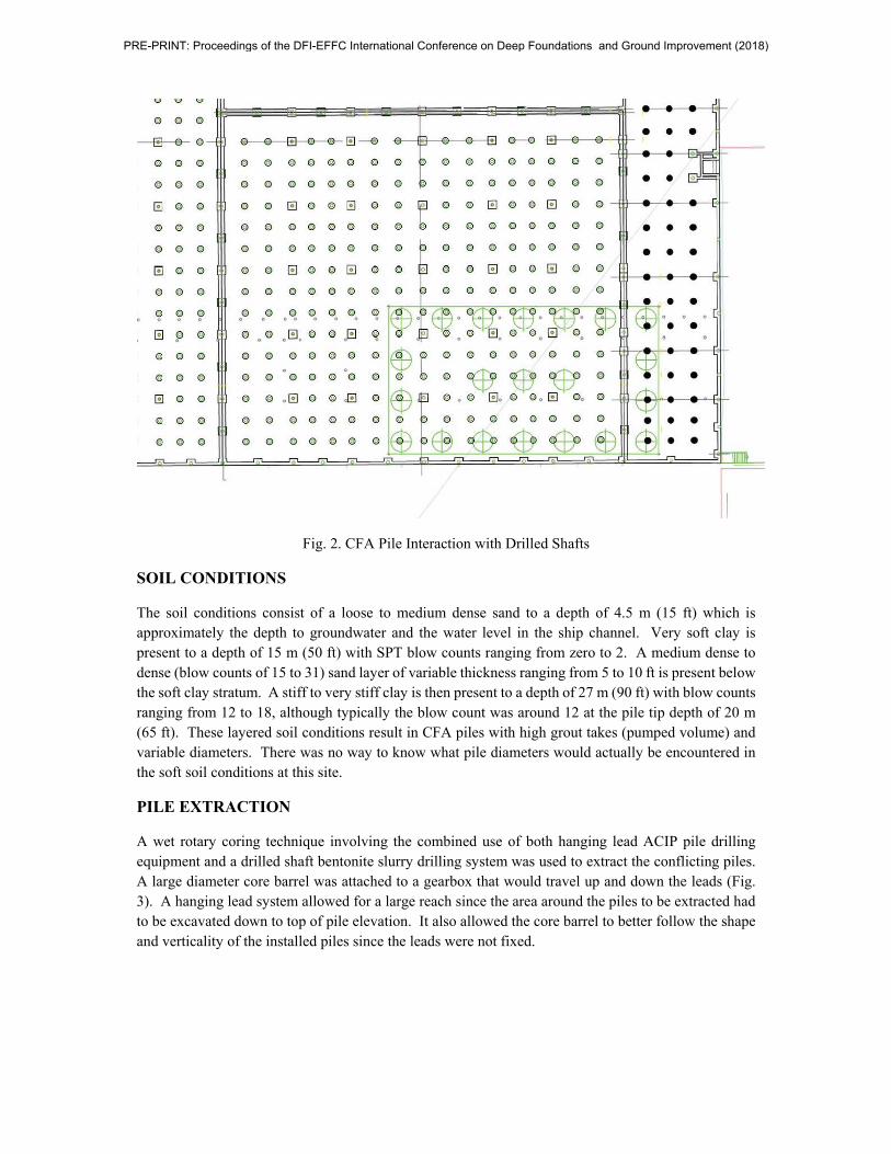
Fig. 2. CFA Pile Interaction with Drilled Shafts
SOIL CONDITIONS
The soil conditions consist of a loose to medium dense sand to a depth of 4.5 m (15 ft) which is approximately the depth to groundwater and the water level in the ship channel. Very soft clay is present to a depth of 15 m (50 ft) with SPT blow counts ranging from zero to 2. A medium dense to dense (blow counts of 15 to 31) sand layer of variable thickness ranging from 5 to 10 ft is present below the soft clay stratum. A stiff to very stiff clay is then present to a depth of 27 m (90 ft) with blow counts ranging from 12 to 18, although typically the blow count was around 12 at the pile tip depth of 20 m (65 ft). These layered soil conditions result in CFA piles with high grout takes (pumped volume) and variable diameters. There was no way to know what pile diameters would actually be encountered in the soft soil conditions at this site.
PILE EXTRACTION
A wet rotary coring technique involving the combined use of both hanging lead ACIP pile drilling equipment and a drilled shaft bentonite slurry drilling system was used to extract the conflicting piles. A large diameter core barrel was attached to a gearbox that would travel up and down the leads (Fig. 3). A hanging lead system allowed for a large reach since the area around the piles to be extracted had to be excavated down to top of pile elevation. It also allowed the core barrel to better follow the shape and verticality of the installed piles since the leads were not fixed.
PRE-PRINT: Proceedings of the DFI-EFFC International Conference on Deep Foundations and Ground Improvement (2018)
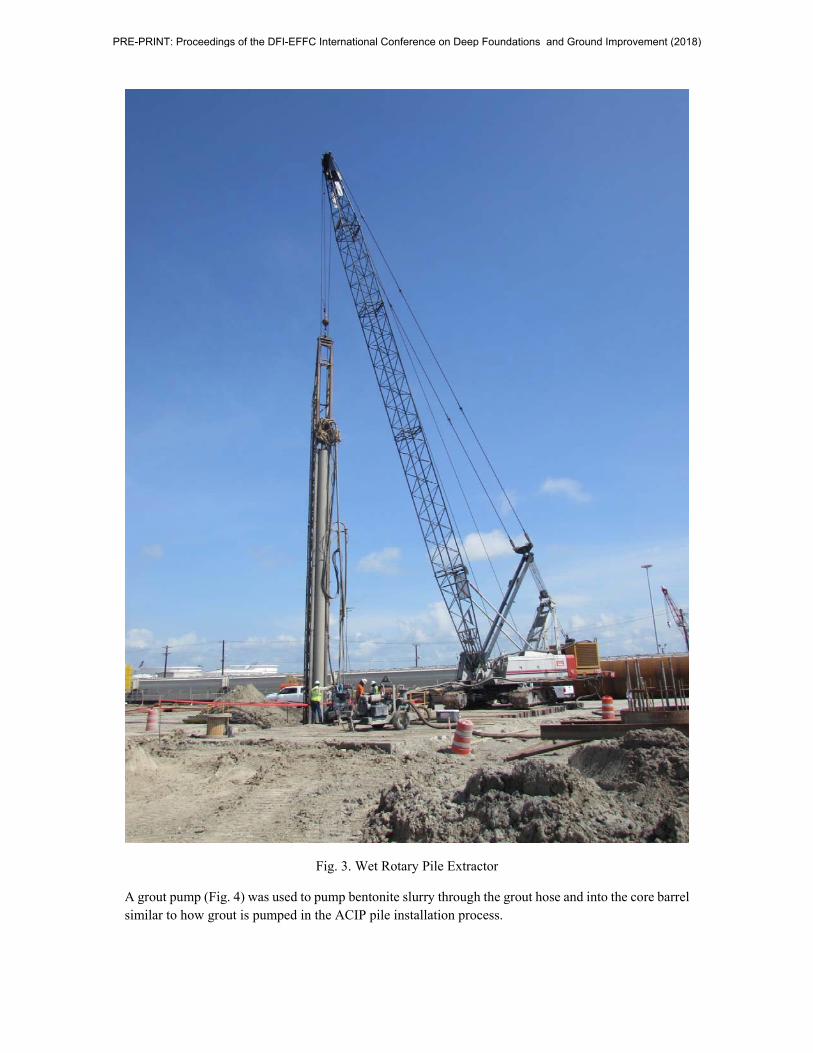
Fig. 3. Wet Rotary Pile Extractor
A grout pump (Fig. 4) was used to pump bentonite slurry through the grout hose and into the core barrel similar to how grout is pumped in the ACIP pile installation process.
PRE-PRINT: Proceedings of the DFI-EFFC International Conference on Deep Foundations and Ground Improvement (2018)
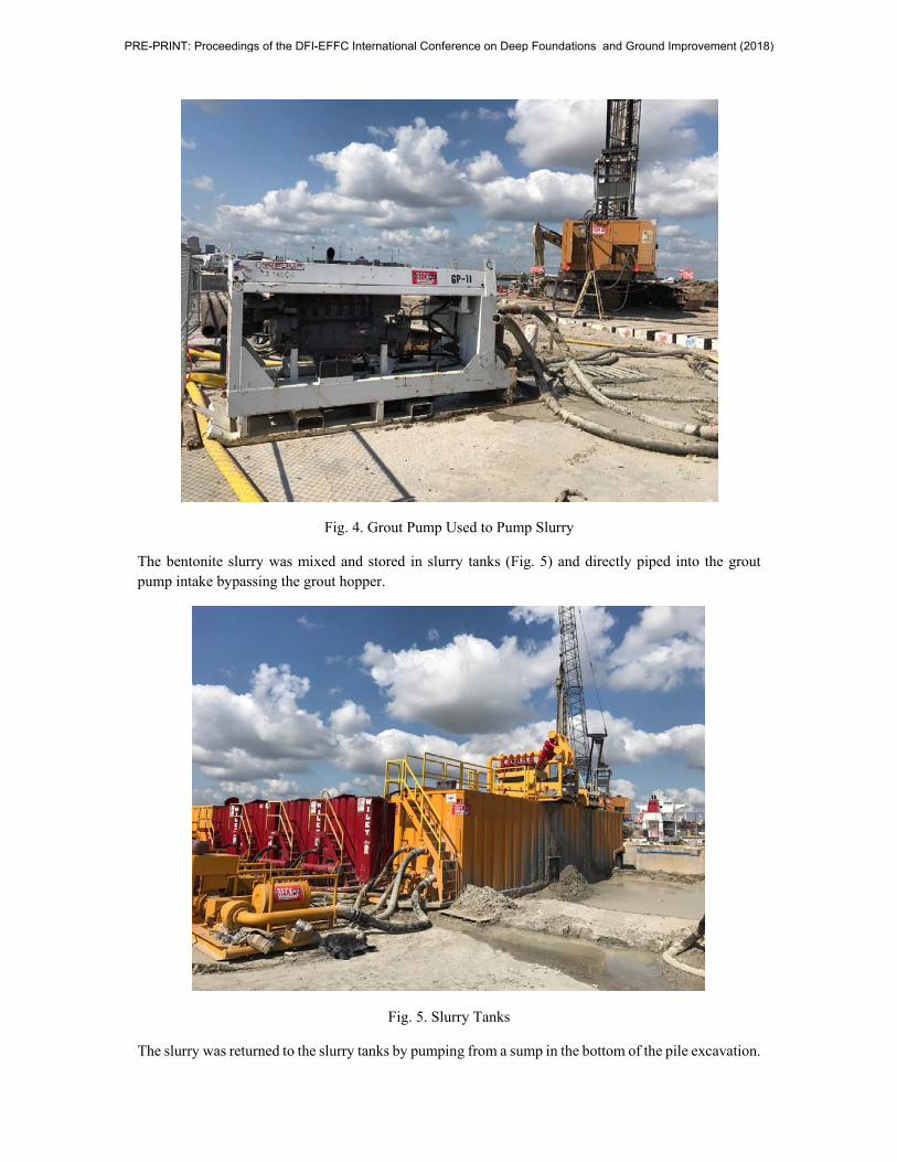
Fig. 4. Grout Pump Used to Pump Slurry
The bentonite slurry was mixed and stored in slurry tanks (Fig. 5) and directly piped into the grout pump intake bypassing the grout hopper.
Fig. 5. Slurry Tanks
The slurry was returned to the slurry tanks by pumping from a sump in the bottom of the pile excavation.
PRE-PRINT: Proceedings of the DFI-EFFC International Conference on Deep Foundations and Ground Improvement (2018)
EXTRACTED PILES
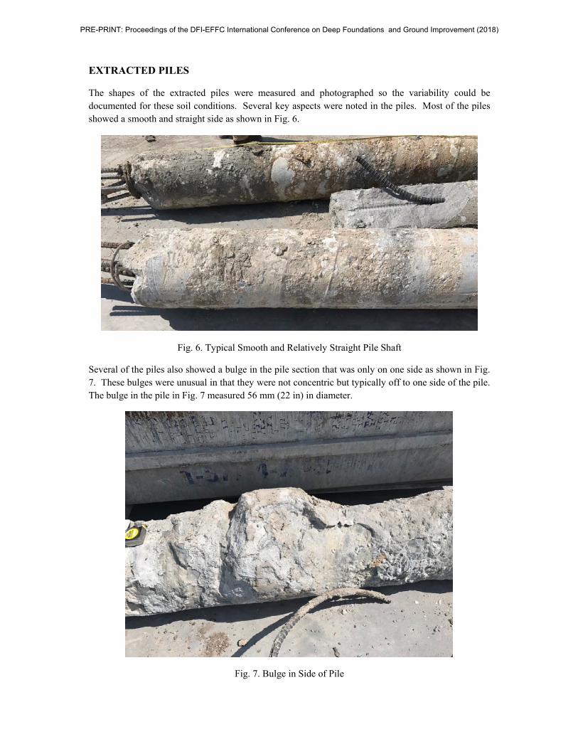
The shapes of the extracted piles were measured and photographed so the variability could be documented for these soil conditions. Several key aspects were noted in the piles. Most of the piles showed a smooth and straight side as shown in Fig. 6.
Fig. 6. Typical Smooth and Relatively Straight Pile Shaft
Several of the piles also showed a bulge in the pile section that was only on one side as shown in Fig. 7. These bulges were unusual in that they were not concentric but typically off to one side of the pile. The bulge in the pile in Fig. 7 measured 56 mm (22 in) in diameter.
Fig. 7. Bulge in Side of Pile
PRE-PRINT: Proceedings of the DFI-EFFC International Conference on Deep Foundations and Ground Improvement (2018)
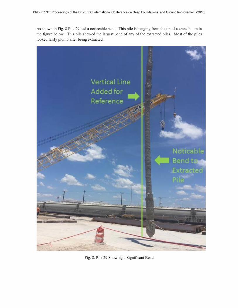
As shown in Fig. 8 Pile 29 had a noticeable bend. This pile is hanging from the tip of a crane boom in the figure below. This pile showed the largest bend of any of the extracted piles. Most of the piles looked fairly plumb after being extracted.
Fig. 8. Pile 29 Showing a Significant Bend
PRE-PRINT: Proceedings of the DFI-EFFC International Conference on Deep Foundations and Ground Improvement (2018)
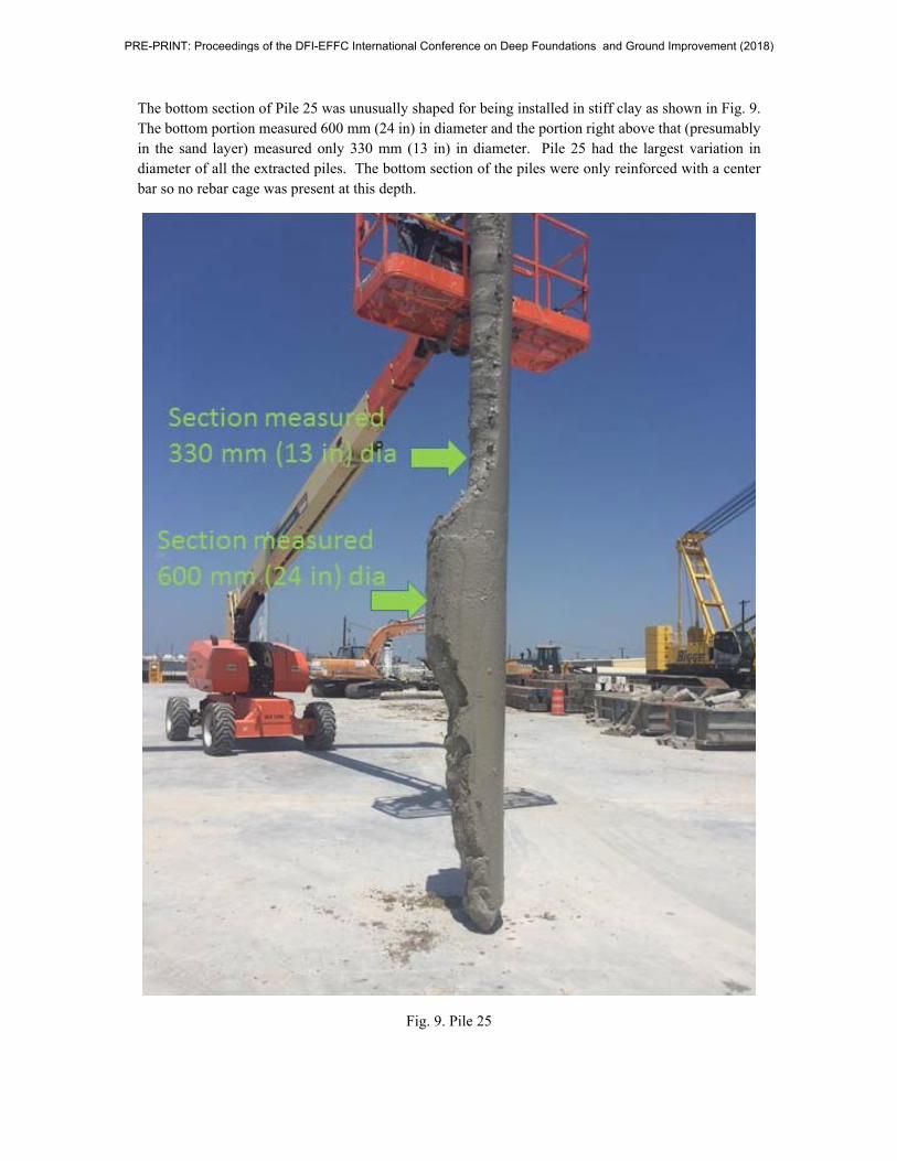
The bottom section of Pile 25 was unusually shaped for being installed in stiff clay as shown in Fig. 9. The bottom portion measured 600 mm (24 in) in diameter and the portion right above that (presumably in the sand layer) measured only 330 mm (13 in) in diameter. Pile 25 had the largest variation in diameter of all the extracted piles. The bottom section of the piles were only reinforced with a center bar so no rebar cage was present at this depth.
Fig. 9. Pile 25
PRE-PRINT: Proceedings of the DFI-EFFC International Conference on Deep Foundations and Ground Improvement (2018)
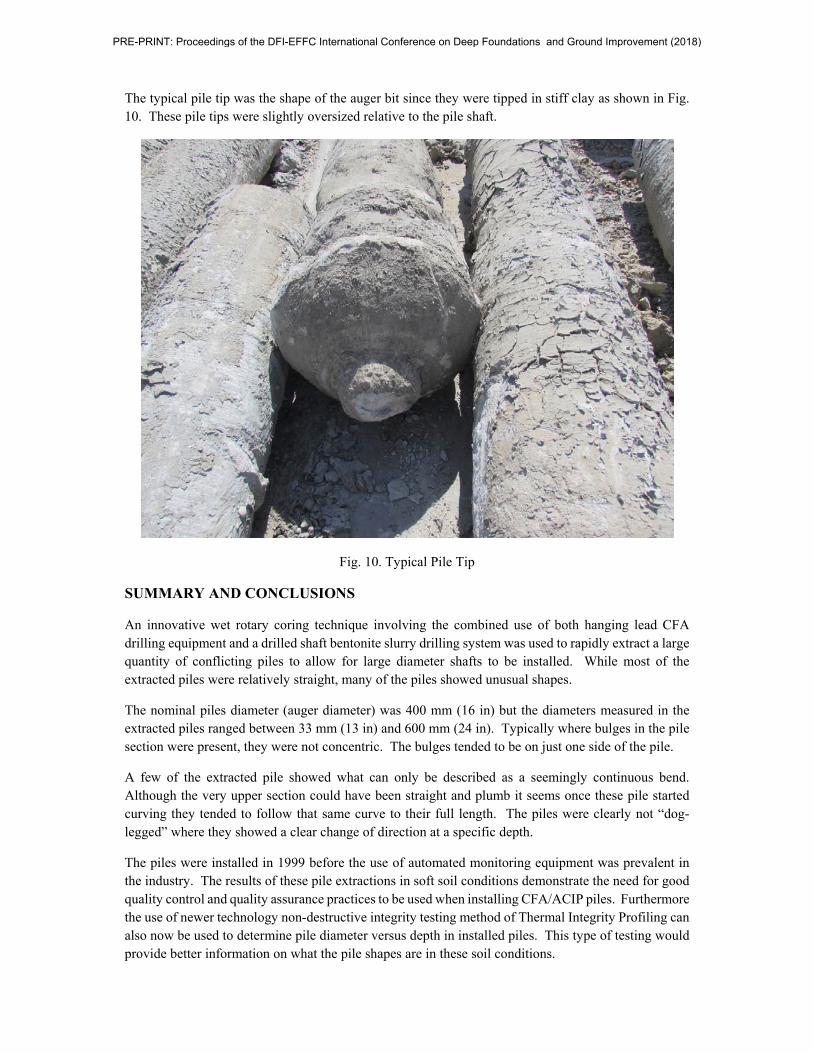
The typical pile tip was the shape of the auger bit since they were tipped in stiff clay as shown in Fig. 10. These pile tips were slightly oversized relative to the pile shaft.
Fig. 10. Typical Pile Tip
SUMMARY AND CONCLUSIONS
An innovative wet rotary coring technique involving the combined use of both hanging lead CFA drilling equipment and a drilled shaft bentonite slurry drilling system was used to rapidly extract a large quantity of conflicting piles to allow for large diameter shafts to be installed. While most of the extracted piles were relatively straight, many of the piles showed unusual shapes.
The nominal piles diameter (auger diameter) was 400 mm (16 in) but the diameters measured in the extracted piles ranged between 33 mm (13 in) and 600 mm (24 in). Typically where bulges in the pile section were present, they were not concentric. The bulges tended to be on just one side of the pile.
A few of the extracted pile showed what can only be described as a seemingly continuous bend. Although the very upper section could have been straight and plumb it seems once these pile started curving they tended to follow that same curve to their full length. The piles were clearly not “dog-legged” where they showed a clear change of direction at a specific depth.
The piles were installed in 1999 before the use of automated monitoring equipment was prevalent in the industry. The results of these pile extractions in soft soil conditions demonstrate the need for good quality control and quality assurance practices to be used when installing CFA/ACIP piles. Furthermore the use of newer technology non-destructive integrity testing method of Thermal Integrity Profiling can also now be used to determine pile diameter versus depth in installed piles. This type of testing would provide better information on what the pile shapes are in these soil conditions.
PRE-PRINT: Proceedings of the DFI-EFFC International Conference on Deep Foundations and Ground Improvement (2018)
PROJECT CREDITS
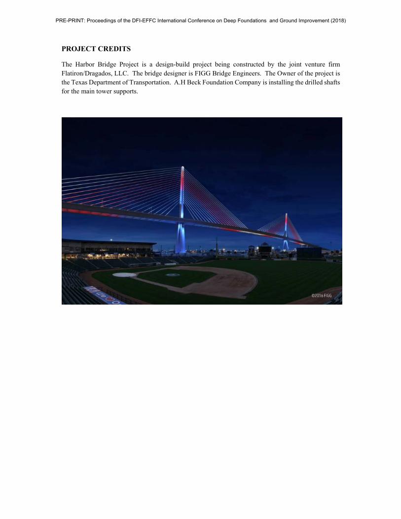
The Harbor Bridge Project is a design-build project being constructed by the joint venture firm Flatiron/Dragados, LLC. The bridge designer is FIGG Bridge Engineers. The Owner of the project is the Texas Department of Transportation. A.H Beck Foundation Company is installing the drilled shafts for the main tower supports.
PRE-PRINT: Proceedings of the DFI-EFFC International Conference on Deep Foundations and Ground Improvement (2018)


![Pile Foundation Design[1] - ITDmtp.itd.co.th/ITD-CP/data/PileFoundationDesign.pdf · Introduction to pile foundations Pile foundation design Load on piles Single pile design Pile](https://img.pdfslide.us/doc/110x75/5a6ffb387f8b9ab1538b8376/pile-foundation-design1-itdmtpitdcothitd-cpdatapilefoundationdesignpdfpdf.jpg)


![[04899] - Design of Pile & Pile-Cap](https://img.pdfslide.us/doc/110x75/5695d3331a28ab9b029d273d/04899-design-of-pile-pile-cap.jpg)