Embed Size (px)
Citation preview

Innovative High-Performance Deposition Technology for Low-Cost
Manufacturing of OLED Lighting Progress Review
John W. Hamer OLEDWorks LLC
2014-05-07 1
OLEDWorks Introduction
• We are the only US manufacturer of OLED lighting panels.
• Founded in Rochester NY in 2010 • 22 full-time OLED experts
– Over 200 years of combined OLED experience – Experience across all areas of OLED technology
• Built a state of the art OLED R&D lab • Designed and started-up a novel, flexible,
scalable OLED production facility. • We have commercialized our first product. • We work with many partners:
– Suppliers to the OLED lighting industry – Downstream luminaire partners.
2014-05-07 2
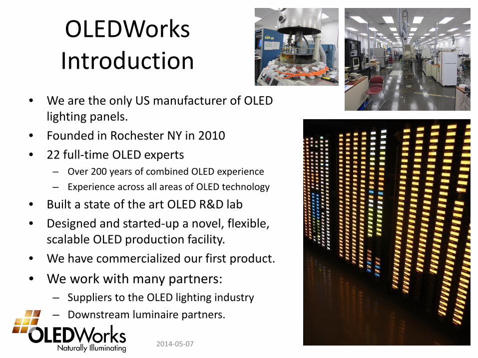
Innovative High-Performance Deposition Technology for Low-Cost
Manufacturing of OLED Lighting • For our novel approach to vaporization, control, and
distribution of organic vapor, the project encompasses: – Design of the production-scale equipment of the deposition
equipment, – Testing, analysis, and improvement of the equipment, – Implementation into production with demonstration
• The goals of this deposition system are: 1. Improve material usage efficiency 2. Improve deposition rate – higher throughput 3. Lead to lower capital cost OLED deposition machines 4. Enable use of thermally sensitive materials
DOE SSL Mfg Workshop 2014-05-07 3
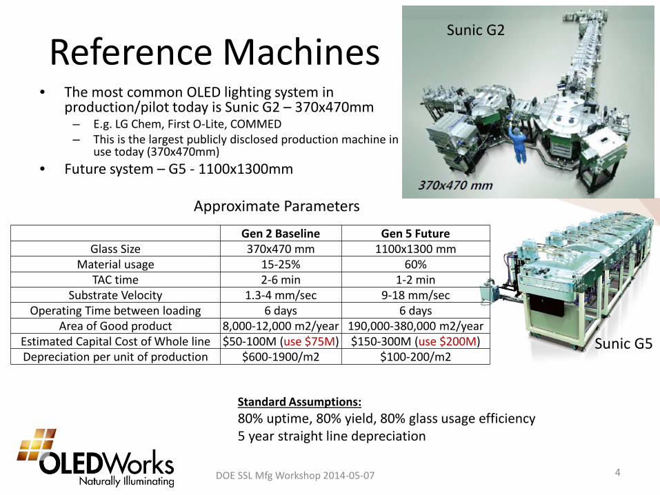
Reference Machines • The most common OLED lighting system in
production/pilot today is Sunic G2 – 370x470mm – E.g. LG Chem, First O-Lite, COMMED – This is the largest publicly disclosed production machine in
use today (370x470mm) • Future system – G5 - 1100x1300mm
DOE SSL Mfg Workshop 2014-05-07 4
Standard Assumptions: 80% uptime, 80% yield, 80% glass usage efficiency 5 year straight line depreciation
Gen 2 Baseline Gen 5 Future Glass Size 370x470 mm 1100x1300 mm
Material usage 15-25% 60% TAC time 2-6 min 1-2 min
Substrate Velocity 1.3-4 mm/sec 9-18 mm/sec Operating Time between loading 6 days 6 days
Area of Good product 8,000-12,000 m2/year 190,000-380,000 m2/year Estimated Capital Cost of Whole line $50-100M (use $75M) $150-300M (use $200M) Depreciation per unit of production $600-1900/m2 $100-200/m2
Sunic G2
Approximate Parameters
Sunic G5
Project Targets in Terms of Reference Machines
DOE SSL Mfg Workshop 2014-05-07 5
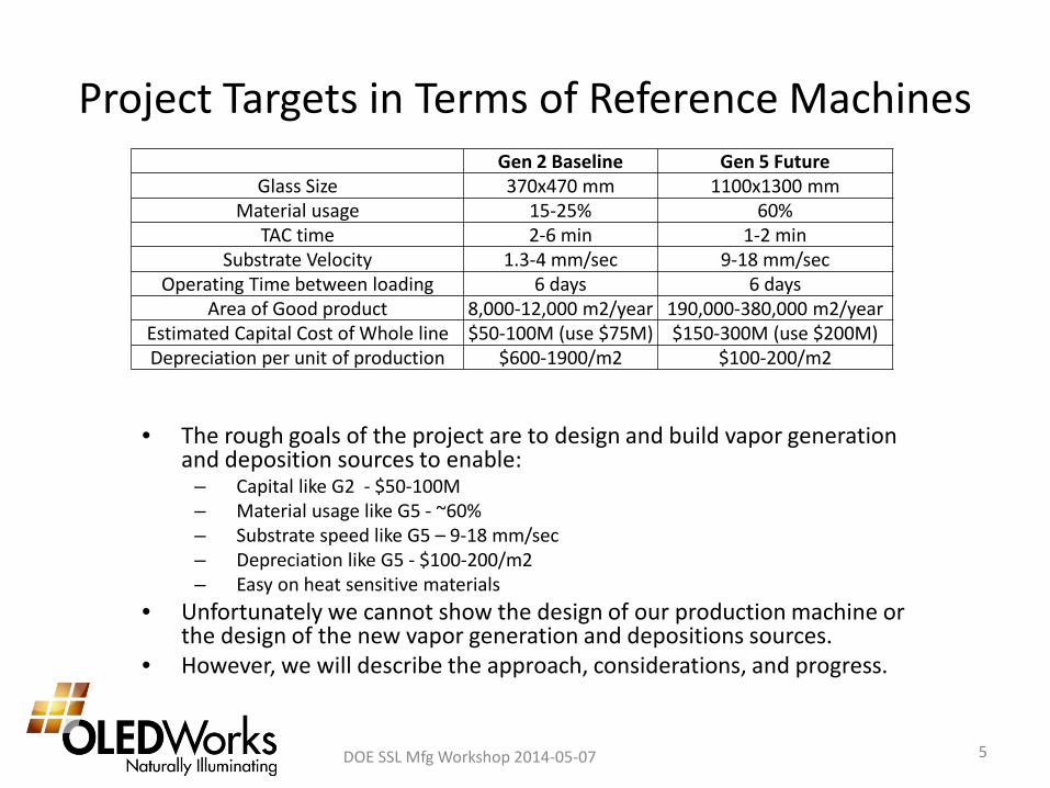
Gen 2 Baseline Gen 5 Future Glass Size 370x470 mm 1100x1300 mm
Material usage 15-25% 60% TAC time 2-6 min 1-2 min
Substrate Velocity 1.3-4 mm/sec 9-18 mm/sec Operating Time between loading 6 days 6 days
Area of Good product 8,000-12,000 m2/year 190,000-380,000 m2/year Estimated Capital Cost of Whole line $50-100M (use $75M) $150-300M (use $200M) Depreciation per unit of production $600-1900/m2 $100-200/m2
• The rough goals of the project are to design and build vapor generation and deposition sources to enable:
– Capital like G2 - $50-100M – Material usage like G5 - ~60% – Substrate speed like G5 – 9-18 mm/sec – Depreciation like G5 - $100-200/m2 – Easy on heat sensitive materials
• Unfortunately we cannot show the design of our production machine or the design of the new vapor generation and depositions sources.
• However, we will describe the approach, considerations, and progress.
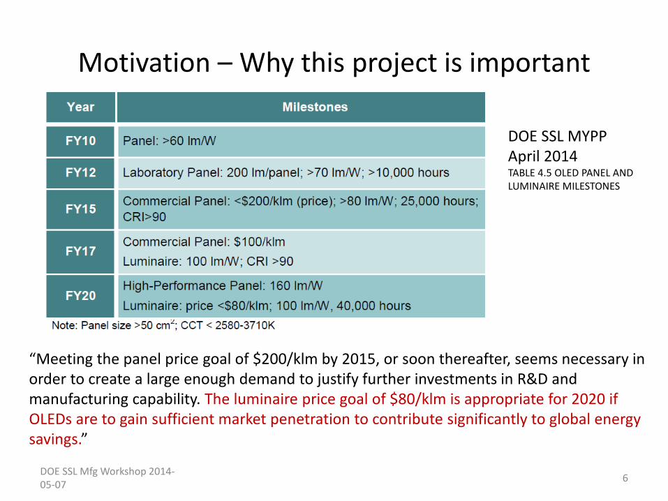
Motivation – Why this project is important
DOE SSL Mfg Workshop 2014-05-07 6
DOE SSL MYPP April 2014 TABLE 4.5 OLED PANEL AND LUMINAIRE MILESTONES
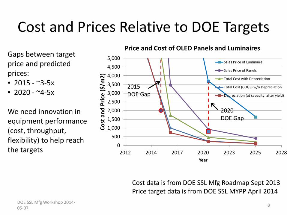
“Meeting the panel price goal of $200/klm by 2015, or soon thereafter, seems necessary in order to create a large enough demand to justify further investments in R&D and manufacturing capability. The luminaire price goal of $80/klm is appropriate for 2020 if OLEDs are to gain sufficient market penetration to contribute significantly to global energy savings.”
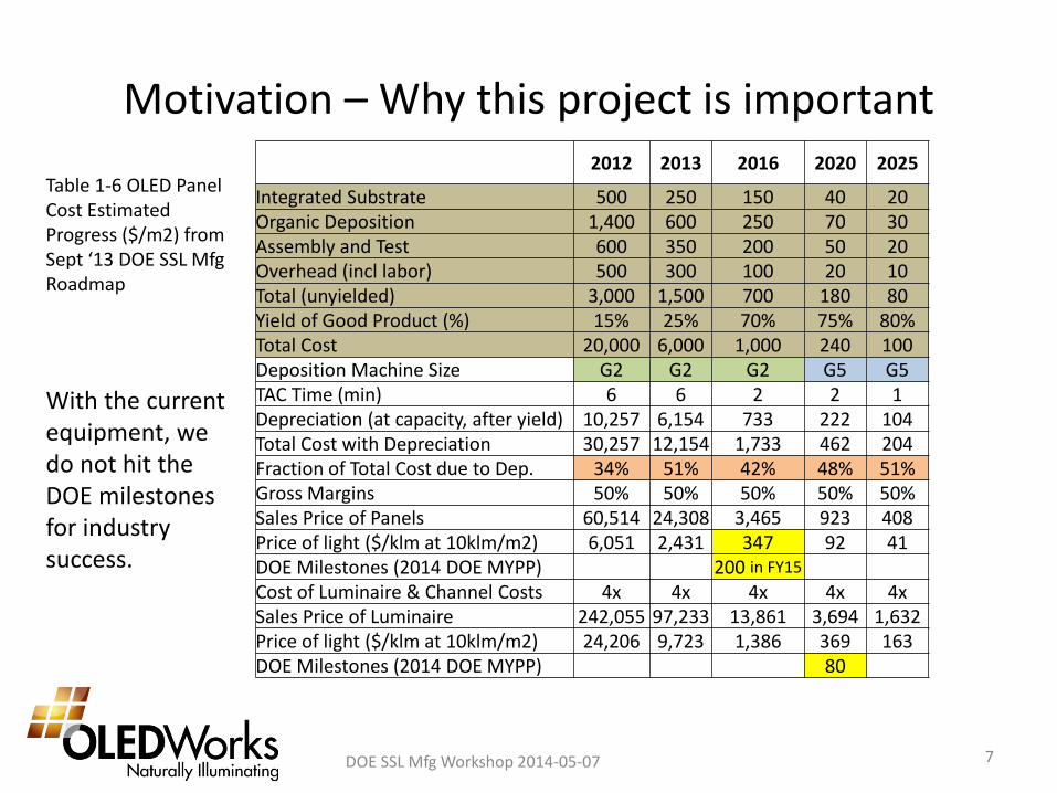
Motivation – Why this project is important 2012 2013 2016 2020 2025
Integrated Substrate 500 250 150 40 20 Organic Deposition 1,400 600 250 70 30 Assembly and Test 600 350 200 50 20 Overhead (incl labor) 500 300 100 20 10 Total (unyielded) 3,000 1,500 700 180 80 Yield of Good Product (%) 15% 25% 70% 75% 80% Total Cost 20,000 6,000 1,000 240 100 Deposition Machine Size G2 G2 G2 G5 G5 TAC Time (min) 6 6 2 2 1 Depreciation (at capacity, after yield) 10,257 6,154 733 222 104 Total Cost with Depreciation 30,257 12,154 1,733 462 204 Fraction of Total Cost due to Dep. 34% 51% 42% 48% 51% Gross Margins 50% 50% 50% 50% 50% Sales Price of Panels 60,514 24,308 3,465 923 408 Price of light ($/klm at 10klm/m2) 6,051 2,431 347 92 41 DOE Milestones (2014 DOE MYPP) 200 in FY15 Cost of Luminaire & Channel Costs 4x 4x 4x 4x 4x Sales Price of Luminaire 242,055 97,233 13,861 3,694 1,632 Price of light ($/klm at 10klm/m2) 24,206 9,723 1,386 369 163 DOE Milestones (2014 DOE MYPP) 80
DOE SSL Mfg Workshop 2014-05-07 7
With the current equipment, we do not hit the DOE milestones for industry success.
Table 1-6 OLED Panel Cost Estimated Progress ($/m2) from Sept ‘13 DOE SSL Mfg Roadmap
Cost and Prices Relative to DOE Targets
DOE SSL Mfg Workshop 2014-05-07 8
0500
1,0001,5002,0002,5003,0003,5004,0004,5005,000
2012 2014 2017 2020 2023 2025 2028
Cost
and
Pric
e ($
/m2)
Year
Price and Cost of OLED Panels and Luminaires
Sales Price of Luminaire
Sales Price of Panels
Total Cost with Depreciation
Total Cost (COGS) w/o Depreciation
Depreciation (at capacity, after yield)
2015 DOE Gap
2020 DOE Gap
Cost data is from DOE SSL Mfg Roadmap Sept 2013 Price target data is from DOE SSL MYPP April 2014
Gaps between target price and predicted prices: • 2015 - ~3-5x • 2020 - ~4-5x We need innovation in equipment performance (cost, throughput, flexibility) to help reach the targets

Large-Scale Production OLED Deposition Equipment Vacuum Thermal Evaporation of Organics
• Organic Vapor Generation and deposition sections
DOE SSL Mfg Workshop 2014-05-07 9
Reference Example – Sunic1 G5 (1100x1300mm) 1 SID 2013, Paper 55.4 Development of Highly Productive In-line Vacuum Evaporation System for OLED Lighting, J.M. Lim et al
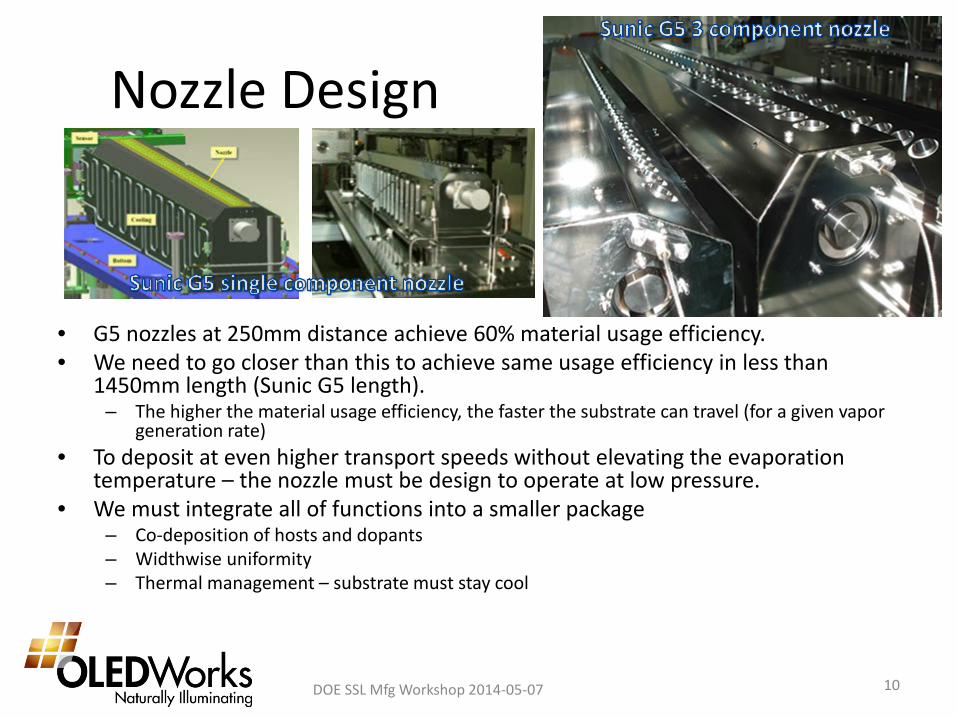
Nozzle Design
DOE SSL Mfg Workshop 2014-05-07 10
• G5 nozzles at 250mm distance achieve 60% material usage efficiency. • We need to go closer than this to achieve same usage efficiency in less than
1450mm length (Sunic G5 length). – The higher the material usage efficiency, the faster the substrate can travel (for a given vapor
generation rate) • To deposit at even higher transport speeds without elevating the evaporation
temperature – the nozzle must be design to operate at low pressure. • We must integrate all of functions into a smaller package
– Co-deposition of hosts and dopants – Widthwise uniformity – Thermal management – substrate must stay cool
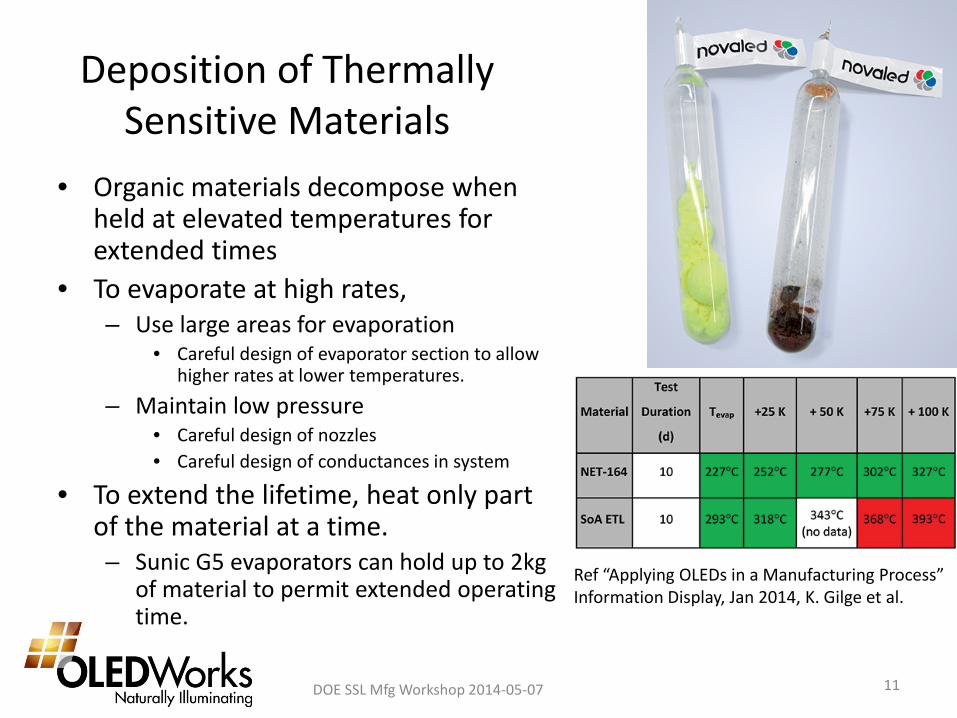
Deposition of Thermally Sensitive Materials
DOE SSL Mfg Workshop 2014-05-07 11
• Organic materials decompose when held at elevated temperatures for extended times
• To evaporate at high rates, – Use large areas for evaporation
• Careful design of evaporator section to allow higher rates at lower temperatures.
– Maintain low pressure • Careful design of nozzles • Careful design of conductances in system
• To extend the lifetime, heat only part of the material at a time. – Sunic G5 evaporators can hold up to 2kg
of material to permit extended operating time.
Ref “Applying OLEDs in a Manufacturing Process” Information Display, Jan 2014, K. Gilge et al.
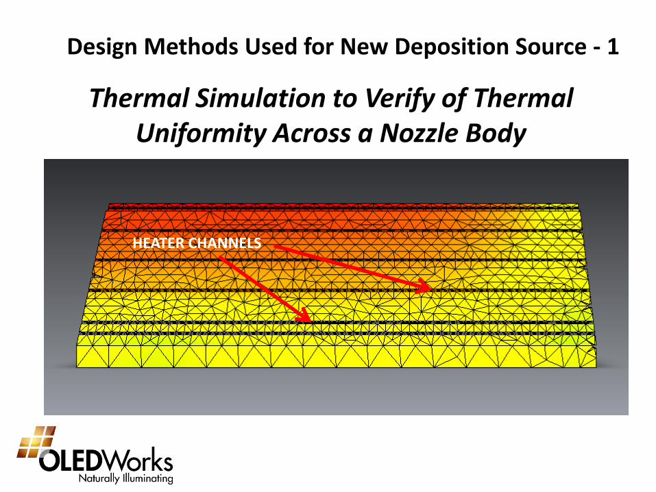
Thermal Simulation to Verify of Thermal Uniformity Across a Nozzle Body
HEATER CHANNELS
Design Methods Used for New Deposition Source - 1
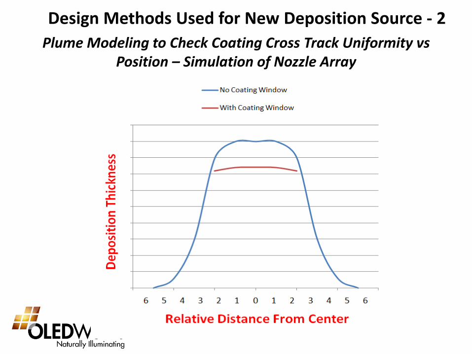
Plume Modeling to Check Coating Cross Track Uniformity vs Position – Simulation of Nozzle Array
Design Methods Used for New Deposition Source - 2
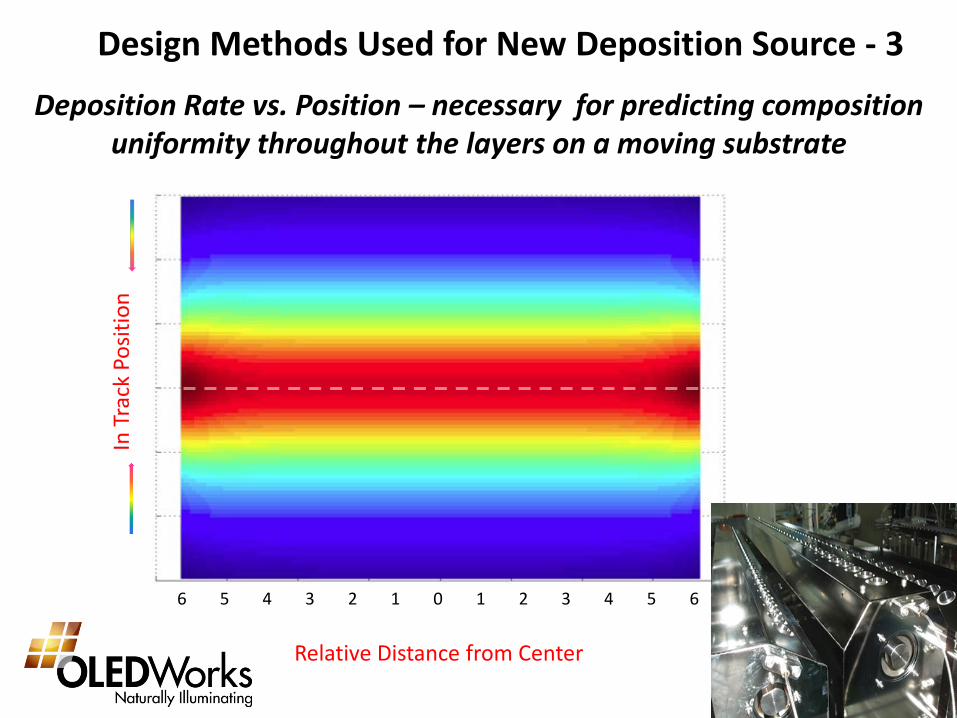
Deposition Rate vs. Position – necessary for predicting composition uniformity throughout the layers on a moving substrate
6 5 4 3 2 1 0 1 2 3 4 5 6
Relative Distance from Center
Design Methods Used for New Deposition Source - 3
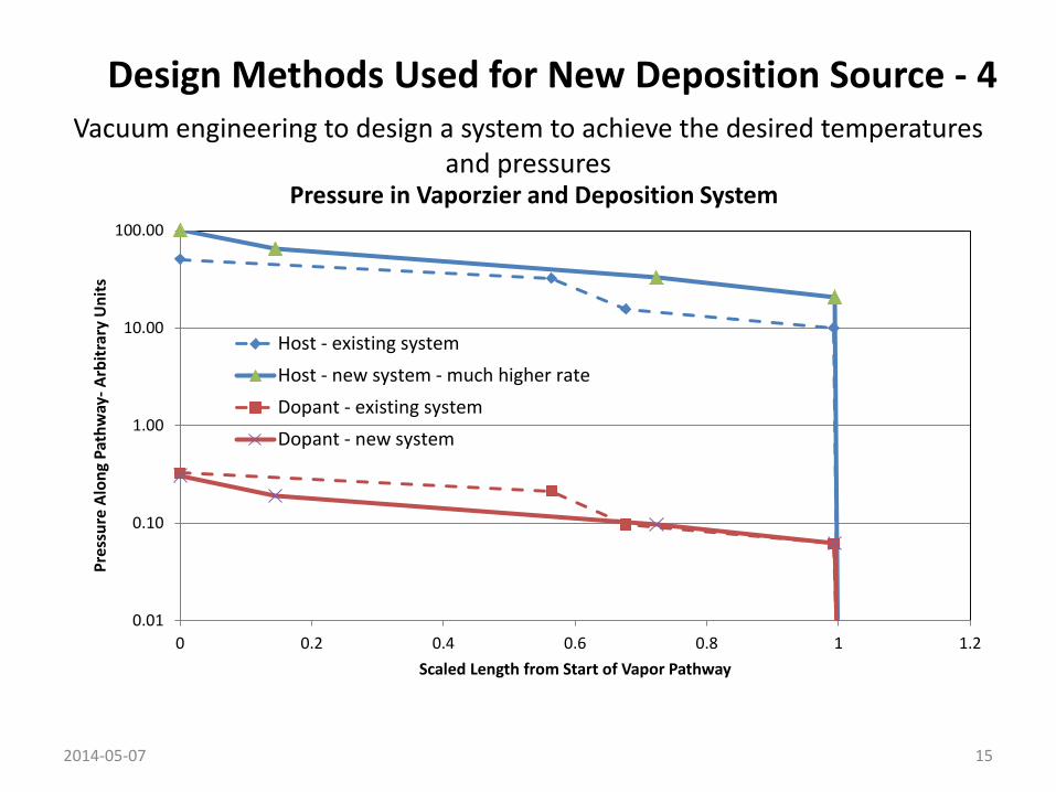
Vacuum engineering to design a system to achieve the desired temperatures and pressures
2014-05-07 15
0.01
0.10
1.00
10.00
100.00
0 0.2 0.4 0.6 0.8 1 1.2
Pres
sure
Alo
ng P
athw
ay- A
rbitr
ary
Uni
ts
Scaled Length from Start of Vapor Pathway
Pressure in Vaporzier and Deposition System
Host - existing systemHost - new system - much higher rateDopant - existing systemDopant - new system
Design Methods Used for New Deposition Source - 4
Integrated Design of Evaporation and Deposition
• The goal is a synergistic design – Smaller system
• Lower capital cost of evaporator and total machine • Closer to substrate
– Higher material usage efficiency » Faster substrate speed
– Manage pressure and temperature • Less stress on materials
– Higher evaporation rates » Faster substrate speeds
• Less degradation of materials – Less downtime for frequent re-loading
» Higher annual throughput
• All parts work together to achieve remarkable results.
DOE SSL Mfg Workshop 2014-05-07 16
Project Overview
• Phase 1 - First year A. Design, build, and test the full scale vaporizer
components B. Refine design C. Design, build, and test single component deposition
system in production equipment with vaporizer. • Phase 2 – Second year
A. Design, build, and test multi-component evaporation deposition system
B. Demonstrate performance in production equipment.
DOE SSL Mfg Workshop 2014-05-07 17
Where are we in the project – 7 months
Project Plan • Phase 1 - First year
A. Design, build, and test the full scale vaporizer components. Where are we after 7 months into the project: • We have completed all design work including
– Vacuum engineering – Thermal modeling – Plume shape modeling
• All major components have been fabricated or are being fabricated.
• Assembly will begin later this month. • We are on schedule and on budget.
DOE SSL Mfg Workshop 2014-05-07 18