Embed Size (px)
Citation preview

Louisiana State UniversityLSU Digital Commons
LSU Doctoral Dissertations Graduate School
2014
Innovative Heat Transfer AugmentationTechniques in Mechanical Face SealNian XiaoLouisiana State University and Agricultural and Mechanical College
Follow this and additional works at: https://digitalcommons.lsu.edu/gradschool_dissertations
Part of the Mechanical Engineering Commons
This Dissertation is brought to you for free and open access by the Graduate School at LSU Digital Commons. It has been accepted for inclusion inLSU Doctoral Dissertations by an authorized graduate school editor of LSU Digital Commons. For more information, please [email protected].
Recommended CitationXiao, Nian, "Innovative Heat Transfer Augmentation Techniques in Mechanical Face Seal" (2014). LSU Doctoral Dissertations. 696.https://digitalcommons.lsu.edu/gradschool_dissertations/696

INNOVATIVE HEAT TRANSFER AUGMENTATION TECHNIQUES IN
MECHANICAL FACE SEAL
A Dissertation
Submitted to the Graduate Faculty of the
Louisiana State University and
Agricultural and Mechanical College
in partial fulfillment of the
requirements for the degree of
Doctor of Philosophy
in
The Department of Mechanical and Industrial Engineering
by
Nian Xiao
M.S., University of Utah, 2005
December 2014

ii
To my parents

iii
ACKNOWLEDGEMENTS
I would like to sincerely thank to Dr. Michael M. Khonsari, my major professor and committee
chairman, for his encouragement, guidance and patience during my studies at the Louisiana State
University. I would also like to thank Dr. Shengmin Guo, Dr. Guoqiang Li, Dr. Joonyoung Jang
and Dr. Louay Mohammad for serving as committee members. Their valuable advices are greatly
appreciated.

iv
TABLE OF CONTENTS
ACKNOWLEDGEMENTS……………………………………………………………………..iii
ABSTRACT ................................................................................................................................. viii
CHAPTER 1 INTRODUCTION ................................................................................................1
1.1 Types of Mechanical Seals ..................................................................................................1
1.2 Mechanical Face Seal ..........................................................................................................1
1.3 Heat Transfer in Mechanical Face Seal ...............................................................................2
1.4 Thermal Problems that Influent Seal Life and Performance ...............................................7
1.5 Outline..................................................................................................................................8
1.6 References ............................................................................................................................9
CHAPTER 2 A REVIEW OF MECHANICAL SEALS HEAT AUGMENTATION
TECHNIQUES ..............................................................................................................................10
2.1 Introduction ........................................................................................................................10
2.2 Mechanical Seal with Heat Exchanger ..............................................................................11
2.2.1 Mechanical seal with no flush flow ............................................................................11
2.2.2 Integrated Mechanical Seal Assembly ........................................................................14
2.2.3 Mechanical Seal with Improved Fluid Circulation .....................................................17
2.2.4 Surface Textural Side-wall of the Stationary Ring (Surface Heat Exchanger) ..........22
2.3 Micro-topography Ring Surface ........................................................................................24
2.4 Conclusions ........................................................................................................................30
2.5 References ..........................................................................................................................30
CHAPTER 3 THERMAL PERFORMANCE OF MECHANICAL SEALS WITH
TEXTURED SIDE-WALL ..................................................................................................................... 33 3.1 Nomenclature .....................................................................................................................33
3.2 Introduction ........................................................................................................................35
3.3 Experimental Facility and Testing Procedure ...................................................................37
3.3.1 Experimental Apparatus ............................................................................................37
3.3.2 Mating Ring Design ...................................................................................................40
3.3.3 Experimental Procedure .............................................................................................42
3.4 Mating Ring Experimental Results and Discussion ..........................................................43
3.5 Dimpled Primary Ring ......................................................................................................46
3.6 Dimples on Both the Primary and Mating Rings ..............................................................50
3.7 Dimpled Seal Ring Thermal Performance ........................................................................51
3.7.1 Dimpled Mating Ring ................................................................................................51
3.7.2 Dimpled Primary Ring ..............................................................................................54
3.8 CFD Predictions .................................................................................................................56
3.8.1 Modeling ....................................................................................................................56
3.8.2 Calculation Results and Comparison .........................................................................58

v
3.9 Conclusions ........................................................................................................................61
3.10 References ..........................................................................................................................62
CHAPTER 4 OPTIMIZATION OF DIMPLES USING NUMERICAL METHODS (CFD
APPROACH) ........................................................................................................................................... 64
4.1 Numerical (CFD) Approach and Procedures ....................................................................64
4.1.1 Modeling ...................................................................................................................64
4.1.2 Comparison of Numerical and Experimental Results ................................................65
4.2 Flow Structure inside a Dimple ........................................................................................67
4.3 Optimizations of Dimples .................................................................................................68
4.4 Thermal Performance Augmentation Using Dimpled Mating Rings ...............................74
4.5 Conclusions .......................................................................................................................80
4.6 References .........................................................................................................................81
CHAPTER 5 THERMAL PERFORMANCE OF MECHANICAL FACE SEAL WITH BUILT-
IN HEAT PIPE ......................................................................................................................................... 82
5.1 Nomenclature .....................................................................................................................82
5.2 Introduction ........................................................................................................................84
5.2.1 Heat Pipe ....................................................................................................................85
5.3 Mating Ring Design and Experimental Procedure ...........................................................88
5.4 Results and Discussions .....................................................................................................90
5.5 Thermal Performance of the Heat-pipe Ring ....................................................................93
5.5.1 The Overall Heat Transfer Performance around Heat Pipe Outer Surface ................93
5.5.2 Side-wall Temperature Distribution ..........................................................................97
5.5.3 Vapor Temperature ..................................................................................................104
5.5.4 Effective Thermal Conductivity of Heat-pipe Ring .................................................105
5.6 Numerical Predictions of Mechanical Seal with Built-in Heat Pipe ...............................107
5.6.1 Example ...................................................................................................................107
5.7 Conclusions .....................................................................................................................108
5.8 References .......................................................................................................................109
CHAPTER 6 TRIBOLOGICAL PERFORMANCE OF HEAT-PIPE RING ......................... 111
6.1 Introduction ......................................................................................................................111
6.2 Heat-pipe Ring ................................................................................................................112
6.3 Design of Heat-pipe Ring ...............................................................................................113
6.4 Experimental Apparatus and Procedure...........................................................................116
6.5 Results and Discussions ..................................................................................................117
6.5.1 Thermal Performance of Heat-pipe Ring .................................................................119
6.5.2 Tribological Performance of Heat-pipe Ring ..........................................................121
6.6 Conclusions .....................................................................................................................127
6.7 References .......................................................................................................................127

vi
CHAPTER 7 SUMMARY AND FUTURE WORKS ................................................................. 129
7.1 Summary ..........................................................................................................................129
7.1.1 Dimpled Surface Texturing Ring .............................................................................129
7.1.2 Built-in Heat-pipe Ring ............................................................................................130
7.2 Recommendation of Future Works ..................................................................................131
APPENDICES ........................................................................................................................................ 132
A. Calculations of the Heat-pipe Ring Effective Thermal Conductivity .................................132
B. Letters of Permission to Use Published Material ................................................................133
VITA ........................................................................................................................................................ 136

vii
ABSTRACT
Excessive heat generated at the face seal contact interface has been recognized as one of main
causes of failure of mechanical seals. In the past few decades various efforts have been attempted
to remove heat from the contact interface uniformly in order to reduce the interfacial temperature,
eliminate thermally-induced failure, and thus increase the life of a mechanical seal. Two innovative
heat transfer augmentation techniques - surface texturing and built-in phase change device - have
been developed in our laboratory to effectively enhance the heat transfer in mechanical face seal.
Surface texturing can increase the surface area, change the near boundary flow structure and
enhance the overall heat transfer rate. Experimental measurements and numerical simulations are
presented that show 10% reduction of a mechanical seal contact face temperature by means of
cylindrically-shaped dimples engraved circumferentially on the outside diameter of a seal ring
(stationary, rotating and/or both rings). A commercially available CFD code (FLUENT) is
employed to numerically confirm the experimental measurements and optimize the dimples based
on their depth-to-diameter ratio, size, arrangement and shapes.
Performance of a prototype mechanical face seal with built-in heat pipe is experimentally
evaluated. The results demonstrate the feasibility of using phase change to remove friction heating
and thus reduce interfacial temperature. In this design, the heat pipe is integrated into the seal
mating ring and there is no need to modify the gland design or the flush arrangement. The results
show that this design is capable of achieving significantly reduction in the seal face temperature
and the friction coefficient. To gain insight into the heat transfer enhancement of the heat pipe seal
ring, a one-dimensional steady state heat transfer analysis is applied to predict the ring wall
temperature distribution and to estimate the saturated vapor temperature. The effective thermal
conductivity of heat pipe ring is estimated. These results of prediction are in good agreement with
experimental measurements.

1
CHAPTER 1 INTRODUCTION
Mechanical seals are among the most crucial components of industrial machinery. They are used
to control leakage from pumps, mixers, agitators, and the like. If a seal fails prematurely, it can
have significant economic and environmental consequences.
1.1 Types of Mechanical Seals
There are two distinct types of seals, static and dynamic seals [1]. Static seals, including gaskets,
O-rings and packings, involve no relative sliding motion at the boundary. On the other hand,
dynamic seals, including non-contact (clearance) seals and radial and axial contact seals, use
relative moving surfaces to restrict flow. Non-contact seals have no solid contact throughout their
life and their faces are separated by certain amount of clearance. Typical non-contact seals are
visco seal, labyrinth seal, bushing seal, floating ring seal and ferrofluid seal. Contact seals have
two opposed faces sliding relative to the other and the clearance between faces is much smaller
than that of non-contact seals. Contact seals are lip seal, circumferential seal, packing and
mechanical face seal. The mechanical face seals are widely used in many industrial applications,
such as compressor, pumps, turbines and etc. Given that the interfacial heat between seal rings is
a major cause of degradation and failure, in this study, we focus our attention to methodologies for
enhancing the thermal performance of mechanical face seals.
1.2 Mechanical Face Seal
A basic schematic of a seal is shown in Figure 1-1. It is a mechanically loaded device consisting
of a rotating (primary) ring and a stationary (mating) ring, having lapped faces that operate in close
proximity under the hydraulic pressure from fluid containment as well as the spring force that

2
pushes the rings together to minimize the leakage between the rotating shaft and the stationary
housing. Generally, the primary face of the mechanical seal is made of a soft material while the
mating face is made of a hard material. Most common material used in primary rings is carbon
graphite which is impregnated with a resin or a metal to reduce porosity. Ceramic, stainless steel,
tungsten carbide and silicon carbide are popular materials for use in mating rings. A secondary
seal such as O-rings are installed between the primary (mating) ring face and the housing or shaft.
During operation, the primary ring rotates against the stationary mating ring and generates
interfacial frictional heat. Flush fluid is supplied to lubricate and remove heat from the interface
between the two rings. The fluid is either from the circulated pumped working fluid or from a
pressurized external barrier fluid reservoir. If taken directly from the process fluid, the flush is
referred to as an “internal flush.” Initially, the seal faces are lapped very flat so that few fluid
leakage occurs. But surface distortion and hydrodynamic or hydrostatic pressure can create a gap
between the ring faces. Thus, the sealed fluid enters into the “contact area” and tends to form a
thin film in between the seal ring contact surfaces. This thin film generally a few of micrometers
separates the contact, lubricates the surfaces, and thus reduces the heat generation and wear.
1.3 Heat Transfer in Mechanical Face Seal
Estimation of the heat generation rate is important in designing a mechanical face seal. The source
of heat generation is the sliding friction at the seal interface and viscous heating of the fluid film
between faces and around the rotating ring. Clearly, for low viscosity fluids, heat is mostly
generated from the former. The frictional heat is a function of load, friction coefficient, rotating
speed and contact area. The load on the contact face consisting of mechanical load (spring force)
and fluid load (fluid pressure) is defined as:

3
Figure 1-1 Mechanical Seal Components
𝑝𝑚 = 𝑝𝑓(𝑏 − 𝑘) + 𝑝𝑠𝑝 (1)
b is the balance ratio which controls the axial loads acting on the seal face. Balance ratio is defined
as the ratio of hydraulic loading area to sealing area, see Figure 1-2 and Eqs. (2), (3) and (4). k is
the pressure gradient factor to account for the shape of the pressure profile and its deviation from
linearity. If assumed linear, k = 0.5; for convex pressure distribution, and for 5.0k 5.0k

4
concave. The value of 0.5 is most commonly used for water and non-flashing fluids. Typically, k
ranges between 0.5 to 0.8. pf is the fluid pressure and psp is the spring pressure.
𝑏 =𝐴𝑓
𝐴𝑐 (2)
For an inside seal, this area ratio is: 𝑏 =(𝐷𝑝
2−𝐵2)
(𝐷𝑝2−𝑑𝑝
2) (3)
For an outside seal, the balance ratio is: 𝑏 =(𝐵2−𝐷𝑝
2)
(𝐷𝑝2−𝑑𝑝
2) (4)
where
Ac the closing area spring acts on (m2)
Af the opening area fluid acts on (m2)
B balance diameter (defined by O-ring or bellows mean diameter) (m)
dp face inner diameter (m)
Dp face outer diameter (m)
The PV parameter is defined as the product of contact face pressure and mean sliding speed. PV is
proportional to the heat generation per unit area at the contact face. When its value reaches a
limiting level, wear rate exacerbates significantly. Therefore, PV limits are essential factors in seal
applications. Table 1-1 lists some representative seal face materials PV limits (water is used as
working fluid in all the tests and the operating temperature is 49oC) [2].

5
Figure 1-2 Balance ratio nomenclature
Table 1-1 Representative PV limits based on seal tests [2]
Primary material Mating material
PV limit
(MPam/s)
Carbon graphite Ni-resist 3.5
Alumina 3.5
Tugngsten carbide 17.5
Silicon carbide 17.5
Carbon graphite 1.8
Tugngsten carbide Tugngsten carbide 4.2
Silicon carbide Silicon carbide 17.5
Note that PV limits are determined by seal ring pair materials and the given tribological
applications. PV limits are also affected by the friction coefficient. Table 1-2 shows the coefficient
of friction for representative face material pair [3].
P1

6
Table 1-2 Coefficient of friction [3]
Primary material Mating material Coeff of friction Range
Carbon graphite Cast iron 0.15 0.07 - 0.15
Alumina 0.18 0.07 - 0.40
Stellite 0.18 0.10 - 0.30
Tugngsten carbide 0.15 0.05 - 0.17
Silicon carbide 0.10 0.02 - 0.12
Tugngsten carbide Tugngsten carbide 0.30 0.10 - 0.40
Silicon carbide 0.18 0.05 - 0.25
Silicon carbide Silicon carbide 0.10 0.05 - 0.15
The heat generation has to be dissipated effectively from the contact faces to avoid the thermal
degradation. Both conduction and convection heat transfer play a significant role on the
performance of a mechanical seal. Since heat conduction occurs as heat flows through the primary
and the mating rings, the thermal conductivity of these materials is important. In addition, heat
generated at the interface between the mating and the rotating rings is dissipated into the flush
fluid through the process of convective heat transfer. In order to remove the heat generated at the
faces effectively, a high heat transfer coefficient and/or a larger wetted area is needed, see Figure
1-3.
Figure 1-3 Heat transfer path in mechanical seal rings

7
1.4 Thermal Problems that Influent Seal Life and Performance
Most mechanical seals fail long before they wear out, and high temperature is identified as one of
main causes of their failure. As pointed out by Lebeck [4], performance of a seal depends largely
on three factors related to the interface temperature. First, when the interfacial temperature is too
high the thin film of lubricating fluid across the gap typically on the order of a few micrometers
may flash to vapor. Anno [5] reported that, for face seals containing micro-asperities, the film
had a thickness varying from about 0.4 µm to 0.2 µm as the applied pressure varied from 1,000 to
70,000 kg/m2. Pape [6] analytically and experimentally studied the lubricant film and concluded
that at the lowest film thickness, the coefficient of friction is higher than the theoretical prediction
because of insufficient lubrication of the faces. The lubricating film is often so thin that excessive
frictional heat generation can result in significant rise in temperature once a part or the whole liquid
film is vaporized. As a result, the seal can be quickly destroyed. Second, many face seal materials
simply cannot withstand exposure to high levels of temperature for a prolong length of time. Also,
operation at very high temperatures can result in failure of other sealing component such as the O-
rings. Another problem is associated with non-uniform heating of seal rings known to cause
distortion of the surfaces and alteration of the interface shape. With non-uniform heating, wear
progressively changes the face profile to compensate for the thermal distortion and affects face
surface finish. Li [7] analyzed the mechanical and thermal deformations of the seal components
and concluded that thermal deformation is more significant than the mechanical deformation, for
it can distort the originally flat sealing surface into slightly convex surface. Doust and Parmar [8]
reached a similar conclusion. They measured the pressure and thermal distortion of seal
components and demonstrated the influence of interface temperature rise on the fluid film
geometry. They also showed that thermal distortion is greater than that caused by pressure,
8
particularly in pump seals that run on hydrocarbons. The frictional heat can result in thermoelastic
deformation which alters the contact pressure distribution. Thermocracking and hot spotting are
example of the problems that occur due to thermal effects. They increase seal wear rate and leakage,
and often lead to premature failure. The interested reader can refer to the work of Kennedy and
Karpe [9] who studied the formation of thermocracking in the mating ring of a mechanical face
seal. They found that the cracks are caused by high tensile residual stresses, which result from the
presence of large thermal stresses at the interface. These seals when operate above a certain critical
speed, enter into a condition known as thermoelastic instability (TEI) that causes localization of
pressure and excessive heat generation that manifest themselves in the form of hot spots at the
sliding interface [10]. Jang and Khonsari [11] developed a model to study thermoelastic instability,
and found that the surface roughness and the hydrodynamic lubrication play important roles on the
instability. Concluded from all the works above, heat transfer is of paramount importance on the
operational performance of a mechanical seal.
1.5 Outline
Two major heat transfer augmentation techniques are dealt in this dissertation: surface texturing
(dimpled surface) and built-in phase change device (heat pipe). The work performer involves
experimental tests with laboratory prototype, theoretical modeling and numerical simulations.
Chapter 2 is the literature review. A review is given to the existing patents dealing with heat
transfer in the mechanical face seals in past twenty years. Chapter 3 is on the topic of surface with
dimpled side-wall. It presents experimental tests on the dimpled mating and primary ring,
estimation of thermal performance of dimpled ring, and numerical simulations. Chapter 4 is about
the dimples’ performance optimization using CFD simulations. Chapter 5 is on the development
of built-in phase change device. It presents tests on a seal prototype with a built-in heat pipe mating

9
ring; modeling of heat pipe ring wall temperature distribution; estimation of heat pipe ring thermal
performance and its effective thermal conductivity. Chapter 6 deals with the tribological
performance of the heat pipe ring, which demonstrates the effect of temperature reduction on the
friction. Chapter 7 is the summary of this dissertation. Some recommendations for the future work
are also given.
1.6 References
[1] Khonsari M.M. and Booser E.R., 2008, Applied tribology, 2nd Ed, Chap 16, Wiley &
Sons,West Sussex, UK.
[2] Booser, E.R., 1997, Tribology data handbook, Chap 66 Dynamic seals, CRC Press.
[3] Buck, G., 1999, “Estimating heat generation, face temperature and flush rate for mechanical
seals,” Proc. Pump Users Expo, pp. 167-172.
[4] Lebeck, A.O., 1991, Principles and design of mechanical face seals, John Wiley & Sons,
NY.
[5] Anno, J.N., 1975, “Hydrodynamic film-thickness determinations in a face seal,” Lubrication
Engineering, 31(3), pp. 132-135.
[6] Pape, J.G., 1968, “Fundamental research on a radial face seal,” ASLE Transaction, 11, pp.
302-309.
[7] Li, C.H., 1976, “Thermal deformation in a mechanical face seal,” ASLE Transaction, 19(2),
pp. 146-152.
[8] Doust, T.G. and Parmar, A., 1986, “An experimental and theoretical study of pressure and
thermal distortions in a mechanical seal,” ASLE Transaction, 29, pp. 151-159.
[9] Kennedy, F.E. and Karpe, S.A., 1982, “Thermocracking of a mechanical face seal,” Wear,
79, pp.21-36.
[10] Barber, J.R., 1969, “Thermoelastic instabilities in the sliding of conforming solids,”
Proceedings of the Royal Society A, 312, pp.381-394.
[11] Jang, J.Y. and Khonsari, M.M., 2000, “Thermoelastic instability with consideration of
surface roughness and hydrodynamic lubrication,” Journal of Tribology, 122, pp. 725-732.

10
CHAPTER 2 A REVIEW OF MECHANICAL SEALS HEAT AUGMENTATION
TECHNIQUES1
2.1 Introduction
In the past few decades various efforts have been attempted to evaluate the thermal performance
of the mechanical face seal in order to effectively remove heat from the interface uniformly, reduce
the interfacial temperature, eliminate thermally-induced failure, and thus increase the life of a
mechanical seal. Merati, et al. [1] experimentally and numerically investigated the thermal
behavior of a mechanical seal. They reported the heat generated at the seal face is mostly convected
to fluid near the interface of the primary and mating rings and the highest temperatures occur near
the inner diameter of the seal face. Doane, et al. [2] also showed that large temperature gradients
only occur in the solid region near interface. Phillips, et al. [3] experimentally determined the
thermal characteristic of a mechanical seal and showed that the fluid velocities in the gap above
the mating ring wear nose between the mating and primary rings are less than those of the bulk
flow field. This impedes heat transfer from the mating ring in the region of the heat generation at
the seal interface. Shirazi et al. [4] numerically predicted the fluid temperature within the seal
housing and concluded that the fluid temperature distribution inside the seal housing is nearly
uniform if a relatively large radial clearance exists between seal rings and housing wall.
From the studies above, we conclude that important factors in the conventional flush cooling
attributed to enhancing heat transfer are: higher flush flow rate and larger radial clearance (gap)
between seal and housing. Hence, heat transfer augmentation devices are often applied close to
seal interface to promote mixing. In order to have a better insight into the existing heat transfer
augmentation techniques applied in the mechanical face seals, a review on the issued or published
1 Reprinted by permission of Journal of Recent Patents on Mechanical Engineering

11
US patents over a 20-year period of 1989-2011 is given. Two major cooling methods investigated
here are: heat exchangers applied in the seal assembly and micro-topography on the seal face.
2.2 Mechanical Seal with Heat Exchanger
A heat exchanger is a device for improving heat transfer from one medium to another. The media
may be separated by a solid wall or may be in direct contact. Heat exchangers have been used for
the purpose of cooling mechanical seals for a long time, but most of them are not installed close
enough to the face surfaces and need complicated heat transfer paths and a large volume of coolant.
An effective heat exchanger should be in close proximity to the seal interface. In what follows,
four types of mechanical seal with heat exchanger designs are discussed. They are seals with no
flush flow, seals with an integrated heat exchanger, seals that offer improved fluid circulation and
those that incorporate surface texture into the design.
2.2.1 Mechanical seal with no flush flow
Most seal flush plans involve recirculation of the fluid being sealed from a pump into seal housing.
The concern is that higher pressure fluid like the fluid from the discharge side of a pump
increases the sealed fluid pressure and results in increasing the interfacial heat generation, and
endanger flashing of the liquid across the face. To reduce the interfacial heat, Drumm [5] patented
a mechanical seal with heat exchanger in 1989. The invention is a design of the annular heat
exchanger 12 as shown in Figure 2-1. The heat exchanger is a hollow body made of high thermal
conductivity material. It comprises of inner and outer cylindrical walls 43 and 44, end walls 45
and 46, and fluid inlet 52 and outlet 54. A series of annual ribs 48 and 50 are fabricated on both of
opposing surfaces to enhance heat transfer. Rotating seal ring 28 is made of a wear resistant
material such as silicon carbide and stationary seal ring 32 is made of softer material such as carbon

12
graphite. Both rings are completely surrounded by the annular heat exchanger. Note that there is a
thin annular fluid zone between sealing rings and heat exchanger. However, there is no direct flush
flow towards the seal faces in this design. The fluid movement is limited to flow around the seal
rings and, therefore, the convective heat transfer near the interface is low. The generated heat at
the interface is dissipated through the thin fluid zone into heat exchanger. For heavily viscous or
other thermo-sensitive fluids as the sealed fluid, this heat exchanger can either introduce heating
or cooling into the seal chamber.
Figure 2-1 A shaft mounted rotary end face seal incorporating a heat exchanger (for the complete
description of numbers see [5])
Murray and Smith [6] patented a fluid cooled seal arrangement named circumferential flow
channel for carbon seal runner cooling for a gas turbine engine in 1997. 22 is the stationary sealing
element made of carbon, and 23 is the rotating sealing element. The cooling fluid, generally engine
oil for high temperature operation, is pressurized to flow through passageway 29 and released
through a series of circumferentially spaced openings 39. The cooling fluid is injected radially into

13
channel 45 by centrifugal forces, which is fabricated in the rotating sealing element 23. When the
cooling fluid completely runs through the channel 45, it flows across the outwardly tapered surface
and back to the oil lubrication system, see Figures 2-2 and 3. The inventors claim that this
arrangement provides a uniform film of cooling fluid, resulting in a more uniform heat transfer
from the rotating sealing element.
Figure 2-2 A partial fragmentary view of the fluid cooled seal arrangement (for the complete
description of numbers see [6])
Figure 2-3 An illustrative end view of fluid passage way and flow channel (for the complete
description of numbers see [6])
Hwang and Pope [7] patented an expanding carbon rings circumferential seal system. Compared
to conventional contracting designs, the carbon rings are placed inside the rotating sealing element

14
(runner) rather than outside. They claim that the oil can be directly impinged on the runner and
have better cooling effect. Gockel and Robinson [8] designed an internally cooled seal housing for
turbine engine. The housing has an enclosed annular groove fabricated in the wall. The cooling
fluid is circulated through the groove to cool down the stationary carbon seal ring and housing.
Takahashi [9] invented an “outside style” mechanical seal in 2011 specially suitable for high
temperature sealed fluids, like those used in thermal power and chemical plants. The inventor
claims no-flush fluid and no-cooler design is needed even when very high temperature fluid is
sealed. The seal unit 1 is installed in a seal cover 5 outside stuffing box 9, see Figures 2-4 and 5.
The inventor recommends using silicon carbide in both stationary ring 7 and rotating ring 8. A
cooling jacket 11 is installed inside the stuffing box 9. The sealed high-temperature fluid is passed
through the gap between cooling jacket and shaft 3. The gap is set to between 0.1 and 0.2 mm. The
high temperature fluid in the extremely small size gap is carried away through the cooling jacket,
which is cooled by water through cooling feed opening 28. The heat generated at seal interface is
dissipated by air or an inert gas flow through quenching opening 16, and reduced temperature
sealed fluid. This mechanical seal design is more compact in size than the conventional one, since
no flushing lines and cooler are used.
2.2.2 Integrated Mechanical Seal Assembly
This kind of mechanical seal has a heat transfer unit integrated into the stationary seal ring to
enhance heat transfer. Winkler et al. [10] designed a mechanical seal assembly with integrated
heat transfer unit in 2011. The unit fitted in the interior of the stationary seal ring 2 has a porous
interior structure, see Figure 2-6. The porous structure 2b is preferably made of silicon carbide.
The coolant is directly flushed through the porous structure and discharged. The inventors claim

15
that the heat transfer unit enables a direct dissipation of heat generated at the seal interface, and
thermal distortions are avoided. The sealing gap temperature can be adjusted to a defined
temperature by controlling the coolant temperature.
Figure 2-4 A front sectional view of entire mechanical seal (for the complete description of
numbers see [9])

16
Figure 2-5 Enlarged view of relevant parts (for the complete description of numbers see [9])
Figure 2-6 A schematic view of a mechanical seal assembly (for the complete description of
numbers see [10])

17
A mechanical seal having a double-tier mating ring was designed Khonsari and Somanchi in 2005
[11]. First stationary ring 4 and second stationary ring 10 in a double-tier ring structure 2 is
illustrated in Figure 2-7. The flush coolant is directed to the first ring 4, which has a series of radial
holes for coolant passing through, see Figure 2-8. Second ring 10 with a circumferential diverter
12 induces coolant mixing, see Figure 2-9. The inventors claim that the presence of coolant in the
interior of stationary ring is effective in reducing heat generation at the seal faces, and shows no
evidence of surface distress.
Figure 2-7 A schematic diagram of the double-tier stationary seal ring (for the complete description
of numbers see [11])
2.2.3 Mechanical Seal with Improved Fluid Circulation
During the mechanical face seal operation, the highest interface temperature generally occurs near
the inner diameter of the stationary ring. The cooling fluid is manipulated to circulate around that
area so as to achieve optimal cooling result. Khonsari and Somanchi designed a stationary seal
ring with a plurality of through-channels to solve the problem in 2007 [12]. Figure 2-10 is a side

18
view of the stationary ring. The inventors claim this design is highly effective in removing heat
from seal faces by channeling the coolant adjacent to the interior surface of seal face. The radial
slots on the stationary ring can minimize clogging and fouling of coolant passages caused by debris
and other contaminants contained in the coolant.
Figure 2-8 First stationary ring (for the complete description of numbers see [11])
Figure 2-9 Second stationary ring (for the complete description of numbers see [11])
19
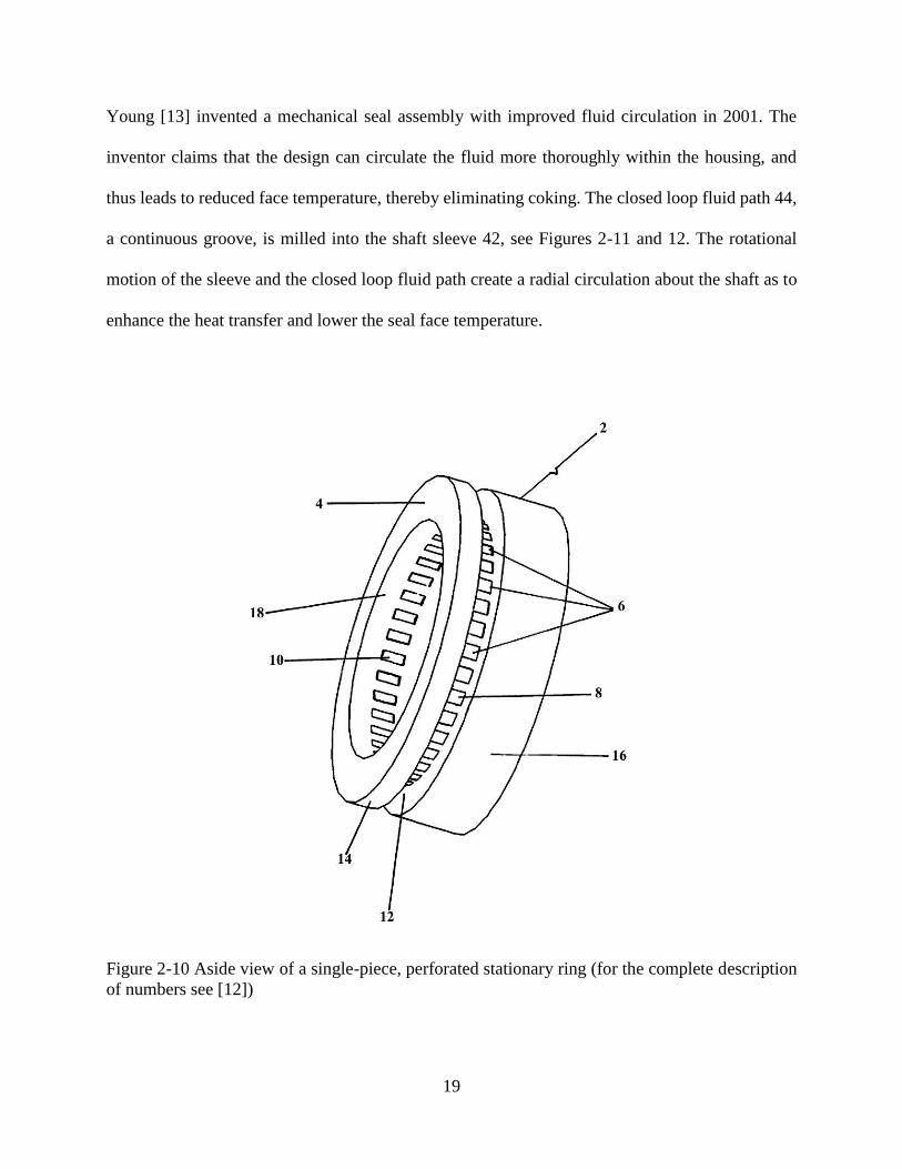
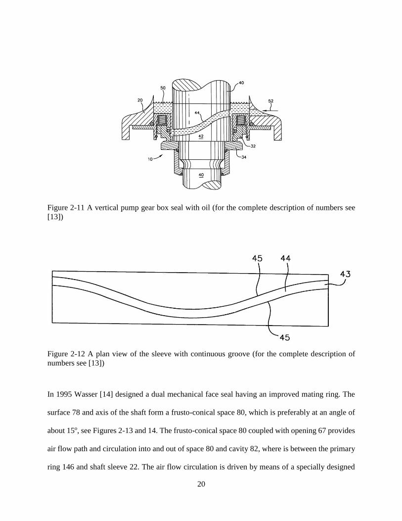
Young [13] invented a mechanical seal assembly with improved fluid circulation in 2001. The
inventor claims that the design can circulate the fluid more thoroughly within the housing, and
thus leads to reduced face temperature, thereby eliminating coking. The closed loop fluid path 44,
a continuous groove, is milled into the shaft sleeve 42, see Figures 2-11 and 12. The rotational
motion of the sleeve and the closed loop fluid path create a radial circulation about the shaft as to
enhance the heat transfer and lower the seal face temperature.
Figure 2-10 Aside view of a single-piece, perforated stationary ring (for the complete description
of numbers see [12])
20
Figure 2-11 A vertical pump gear box seal with oil (for the complete description of numbers see
[13])
Figure 2-12 A plan view of the sleeve with continuous groove (for the complete description of
numbers see [13])
In 1995 Wasser [14] designed a dual mechanical face seal having an improved mating ring. The
surface 78 and axis of the shaft form a frusto-conical space 80, which is preferably at an angle of
about 15o, see Figures 2-13 and 14. The frusto-conical space 80 coupled with opening 67 provides
air flow path and circulation into and out of space 80 and cavity 82, where is between the primary
ring 146 and shaft sleeve 22. The air flow circulation is driven by means of a specially designed

21
drive collar 90. The inventor claims that this kind of arrangement provides additional cooling to
the sealing rings and can effectively lower the temperature of at least the outboard seal of a dual
mechanical face seal.
Azibert and Clark [15] patented a stationary seal ring with inclined inner surface relative to the
outer surface of shaft sleeve. They claim their design promote the fluid circulation and effectively
remove heat. Hornsby [16] designed a plurality of tapered axial notches on the shaft sleeve
underneath the stationary seal ring to enhance pump effect and achieve a better circulation of
barrier fluid.
Figure 2-13 A partial cross-sectional view of the dual seal system (for the complete description of
numbers see [14])

22
Figure 2-14 A detailed cross-sectional and side view of sealing ring (for the complete description
of numbers see [14])
2.2.4 Surface Textural Side-wall of the Stationary Ring (Surface Heat Exchanger)
Given that the available space for heat transfer inside a seal chamber is limited, one may take
advantage of surface heat transfer augmentation by means of texturing the surfaces to increase the
effective area for convective heat transfer. The common textures include surface roughness,
grooves, dimples and ribs. A seal ring with textural surface can also increase mixing around the
seal faces since the maximum heat flux occurs on the rotating ring surface near the interface
between the rotating and stationary rings [1]. Another advantage of surface texture is that this
technique can be applied in the conventional flushing seal chamber. The surface texturing is
preferably used for seal mating ring, which is made of hard material. The primary ring is generally
made of a softer material. One of the designs has been by Khonsari and Gidden in 2008 [17].
Single circumferential groove 5 is shown in Figure 2-15 and double grooves 5 and 7 are shown in
Figure 2-16. A series of subdivided fins 9 are shown in Figure 2-17. Experimental tests were
conducted using both conventional stationary ring and the textural ring. Under identical condition
the interface temperature of the textural ring was reduced from 49 oC to 43.5 oC.

23
Figure 2-15 A stationary ring with a single circumferential groove (for the complete description of
numbers see [17])
Figure 2-16 A stationary ring with double circumferential grooves (for the complete description
of numbers see [17])

24
Figure 2-17 A stationary ring with groove and subdivided fins (for the complete description of
numbers see [17])
Surface texturing simply in the form of dimples have been widely used in electronics cooling, heat
exchangers, turbine blade internal cooling passages, etc. Dimpled surface can increase surface area
and generate vortices to enhance mixing. It also has less pressure drop than most of other textures,
which is important to avoid fluid vaporizing due to significant pressure drop.
2.3 Micro-topography Ring Surface
The sealing gap between seal faces must be maintained very narrow to prevent flow leakage
through the gap. Heat generation and wear increase if the gap is too small. Research shows that
micro-topography produced directly on the surface of the mating ring provides some fluid pressure
in the gap and effectively separates the sealing faces. The total applied separating load (i.e., the
opening force) is supported by the hydrostatic and hydrodynamic fluid pressure. However, proper
balance is needed since too much fluid pressure between the mating and primary ring can result in
excessive leakage. Thus, seal gap must be carefully designed to provide enough fluid pressure and
minimize leakage. Extensive research efforts have been directed to the studies of micro-

25
topography on the seal faces in the last decade. The partial surface texturing can introduce
hydrostatic pressure build up in the sealing dam. Etsion and Halperin [18] theoretically optimized
the face pattern parameter to obtain maximum hydrostatic pressure effect. Yu, et al. [19] measured
the interface temperature rise using a seal face with micro-pores pattern and a conventional seal,
and found that the temperature rise of a laser-patterned seal face is about 30% less than that of the
conventional seal. The result showed that the hydrodynamic pressure is built up in the micro-pores
to separate the rings surface and reduce heat generation. Grooves, such as spiral grooves and T-
grooves, are typical hydrodynamic face patterns. Lai [20] designed a face seal with double spiral
grooves in 1993. The inventor claims that the double spiral pumping groove configuration, made
on either the primary or the mating ring face, achieves the desired gap between the seal faces and
substantially minimize the fluid leakage between the faces. The grooves on the primary ring face
were produced by etching on the primary ring face, and their depth is preferably from about 5 𝜇𝑚
to about 8 𝜇𝑚. The downstream pumping grooves 71 pump the high pressure fluid from housing
65 in between seal faces provide the desired gap. Upstream grooves 73 pump fluid back to the
housing so that fluid leakage is minimized, see Figure 2-18. The relative lengths of radial
projection of the spiral grooves 71, 73 are expressed by the ratios:
3 ≥ 𝑑2/𝑑1 ≥1
3
and
1 ≥ 𝑑3/𝑑1 ≥ 0

26
Figure 2-18 A seal ring face provided with one preferred embodiment of spiral pumping grooves
construction (for the complete description of numbers see [20])
Muller [21] patented several seal face patterns in 1996. The patterns are formed by means of laser
beams on the sliding surface of ceramic sealing rings and their depth is from 1 micrometer to a
few micrometers. One of the inventions includes stepped hollows in the rotating ring seal face to
create a hydrodynamic load support, see Figure 2-19. Fluid enters the additional depression 51,
which is open towards the seal ring edge, by fluid pressure. The fluid is out of depression 51 into
the sealing gap as the rotating ring slides over the stationary ring. Then, the fluid entrains into a
cascade hollows from shortest 424 to longest 421. As the fluid accumulates inside the hollows, the
hydrodynamic pressure is built up at the shallowest end 420 of 421. When the entrained fluid
pressure is higher than outside fluid pressure, the fluid entrained inside the hollows is ejected back
to the seal housing. Many other patents using the hydrodynamic patterns were also issued in past
20 years; some examples are in [22]-[31].

27
Figure 2-19 The flow path through hollow shaped depressions and additional depresstion (for the
complete description of numbers see [21])
Lebeck and Young [32] were issued a patent for wavy-tilt-dam seal ring in 1989. The inventors
claim that the type of face shape of the ring can promote hydrostatic and hydrodynamic lift and
minimize leakage. The wavy-tilt-dam shape was ground or machine contoured onto the primary
ring made of tungsten carbide, silicon carbide or stainless steel. The number of waves is
determined by the stiffness or conformability of the primary ring or opposing seal ring. The most
preferably amplitude of the waviness is about 2.5 𝜇𝑚 . The waves 19 are formed in a
circumferential direction on the face the ring. The waves 19 and tilts 20 are acted to enhance
lubrication and reduce friction. The dams 21, the flat areas, tend to minimize leakage, see Figures
2-20 and 21.

28
Figure 2-20 Nine waves on the face of the ring (for the complete description of numbers see
[32])
Figure 2-21 Contact of the mating ring with primary ring (for the complete description of numbers
see [32])

29
Today, most face patterns are fabricated by laser beam. Young and Staloch [33] were issued a
patent for applying micro-topography to mechanical seal faces using an excimer laser in 2007. The
wave and other hydrodynamic face geometries are applied on the seal face of mechanical seals for
rotary rock bits, examples are in [34] and [35].
The use of MEMS based micro-structures or micro-roughness methods can enhance lubrication
and heat transfer in bearings and mechanical seals. Stephens and Kelly patented [36] a high aspect
ratio microstructures (HARMs) employed to cover load-bearing surface of mechanical seals or
bearings, see Figure 2-22. The microstructure can be microchannels or microposts. They claim the
HARMs microstructure, used as heat sink and fluid/solid lubricant storage and distribution, can
effectively enhance heat transfer and provide lubricant to the load-bearing surface. The HARMs
mircostructure is fabricated using LIGA process on a nickel alloy or a ceramic. The aspect ratio
for mechanical seals are recommended to be between about 0.5 and about 50, preferably between
about 1 an about 10. Another patent of HARMs is in [37]. Lebeck [38] patented a seal interface
having area different in roughness. The inventor claimed this design can supply asperity tip load
support to opposing interface.
Figure 2-22 A field of square nickel posts fabricated with the LIGA process ((for the complete
description see [36])

30
2.4 Conclusions
The review of mechanical seal cooling techniques in this article has shown different approaches
to deal with heat generation at the seal faces. This review is based on patents issued over the
twenty-year span (1989-2011). The patents issued and patent applications range from simple heat
transfer devices add-on in the mechanical seal assembly to more radical changes in the
conventional mechanical seal arrangement. The authors believe that, ideally, a good design of
mechanical seal unit should be easy to fabricate, install, dramatically increase the seal service life
and cost-effective. Some of designs can be combined to generate better heat transfer augmentation
and reduce wear.
2.5 References
[1] Merati, P., Okita, N.A., Phillips, R.L. and Jacobs, L.E., 1999, “Experimental and
computational investigation of flow and thermal behavior of a mechanical seal,” Tribology
Transaction; 42(4), pp. 731-738.
[2] Doane, J.C., Myrum, T.A. and Beard, J.E., 1991, “An experimental-computational
investigation of the heat transfer in mechanical face seals,” International Journal of Heat
and Mass Transfer, 34, pp. 1027-1041.
[3] Phillips, R.L., Jacob, L.E. and Merati, P., 1997, “Experimental determination of the thermal
characteristics of a mechanical seal and its operating environment,” Tribology Transaction,
40(4), pp. 559-568.
[4] Shirazi, S.A., Soulisa, R., Lebeck, A.O. and Nygren, M.E., 1998, “Fluid temperature and
film coefficient prediction and measurement in mechanical face seals-numnerical results,”
Tribology Transaction, 41(4), pp. 459-470.
[5] Drumm K.R. Mechanical seal with heat exchanger. US4872689 (1989).
[6] Murray S.G, Smith J.C. Circumferential flow channel for carbon seal runner cooling.
5593165 (1997).
[7] Hwang M.F, Pope A.N. Expanding circumferential seal with upper-cooled runner. 5301957
(1994).

31
[8] Gockel R.R, Robinson J.D. Internally-cooled seal housing for turbine engine. US7410341
B2 (2008).
[9] Takahashi H. Mechanical seal. US2011/0198813 A1 (2011).
[10] Winkler A, Otschik J, Schicktanz R. Mechanical seal assembly with integrated heat transfer
unit. US2011/0169225 A1 (2011).
[11] Khonsari M.M, Somanchi A.K. Mechanical seal having a double-tier mating ring.
US6942219 B2 (2005).
[12] Khonsari M.M, Somanchi A.K. Mechanical seal having a single-piece, perforated mating
ring. US7252291 B2 (2007).
[13] Young L.A. Mechanical seal assembly with improved fluid circulation. US6296254 B1
(2001).
[14] Wasser J.R. Mechanical end face seal having an improved mating ring. 5468002 (1995).
[15] Azibert H.V, Clark A.R. Method and apparatus for optimizing barrier fluid flow for
promoting cool running of a cartridge dual seal. 5938205 (1999).
[16] Hornsby J. Mechanical seal with barrier fluid circulation system. 5217234 (1993).
[17] Khonsari M.M, Gidden A. Mechanical seal with superior thermal performance. US2008/0237995 A1 (2008).
[18] Etsion, I. and Halperin, G., 2002, “A laser surface textured hydrostatic mechanical seal,”
Tribology Transaction, 45(3), pp. 430-434.
[19] Yu, X.Q., He, S. and Cai, R.L., 2002, “Frictional characteristics of mechanical seals with a
laser-textured seal face,” Journal of Materials Processing Technology, 129, pp. 463-466.
[20] Lai W.T. Face seal with double spiral grooves. 5201531 (1996).
[21] Muller H.K. Floating ring seal with return structures and process for making it. 5529317
(1996).
[22] Heck J.A, Wilhelm, H.R. Gas face seal. 5066026 (1991).
[23] Matsui S. Gas seal. 5447316 (1995).
[24] Lipschitz A, Warwick R.I. Circumferential inter-seal for sealing between relatively
rotatable concentric shafts. 4972986 (1990).
[25] Lahrman KA. Fluid bearing face seal for gas turbine engines. 5174584 (1992).

32
[26] Pecht G.G, Hamaker J. Non-contacting, gap-type seal having a ring with a patterned
microdam seal face. 5090712 (1992).
[27] Fuse T, Okumachi E. Non-contacting shaft sealing device. 5529318 (1996).
[28] Victor K.H, Maser G, Laarmann H.W, Dedeken R. Contactless pressurizing-gas shaft seal.
5092612 (1992).
[29] Takenaka A, Fukuoka T. Mechanical seal. 5538260 (1996).
[30] Gardner JF, Exeter R.I. Spiral groove gas lubricated seal. 5039113 (1991).
[31] Edling J.K.J, Jacobsson R.A. Grooved run-in face seal. 5575486 (1996).
[32] Lebeck A.O, Young L.A. Wavy-tilt-dam seal ring. 4836561(1989).
[33] Young L.A, Staloch J.R. Seal ring and method of forming micro-topography ring surfaces
with a laser. US7194803 B2 (2007).
[34] Pearce D.E. Face seal having strain induced face geometry. 6109376 (2000).
[35] Burr B.H. Rock bit face seal having lubrication gap. 6427790 (2002).
[36] Stephens L.S, Kelly K.W. Bearings and mechanical seals enhanced with microstructures.
6280090 (2001).
[37] Stephens L.S, Kelly K.W. Mechanical seals enhanced with microstructures. 6149160 (2000).
[38] Lebeck A.O. Differential surface roughness dynamic seals and bearings. 4834400 (1989).

33
CHAPTER 3 THERMAL PERFORMANCE OF MECHANICAL SEALS WITH
TEXTURED SIDE-WALL2
3.1 Nomenclature
Am – mating ring outer surface flush area (m2)
Ap – primary ring outer surface flush area (m2)
𝐶𝑝 – flush fluid specific heat (J/kgK)
Dm – outer diameter of mating ring (m)
Dp – outer diameter of primary ring (m)
Dw – median diameter between outer and inner diameter of primary ring (m)
ℎ𝑐 – overall heat transfer coefficient of seal housing (W/ (m2
K))
ℎ𝑚 – overall heat transfer coefficient between mating ring wall and flush fluid (W/ (m2
K))
ℎ𝑝 – overall heat transfer coefficient between primary ring wall and flush fluid (W/ (m2
K))
Kf – flush fluid thermal conductivity (W/ (mK))
Kp – primary ring thermal conductivity (W/ (mK))
Lp – length of the primary ring (m)
�� – flush mass flow rate (kg/s)
2 Reprinted by permission of Journal of Tribology International

34
ml – defined in Eq.(4)
𝑁𝑢𝑝 – overall Nusselt number around primary ring outer surface
Pr – Prandtl number
qm – heat dissipation from mating ring outer surface (W)
qp – heat dissipation from primary ring outer surface (W)
qout – total heat dissipation by the flush fluid (W)
rpo – primary ring outer radius (m)
rpi – primary ring inner radius (m)
Re – Reynolds number
𝑇𝑖𝑛 – flush inlet temperature (oC)
𝑇𝑚𝑠 – mating ring outer surface temperature (oC)
To – ambient fluid temperature (oC)
𝑇𝑜𝑢𝑡 – flush outlet temperature (oC)
W – friction face width (m)
𝛾 – heat partitioning factor, defined in Eq.(7)
𝜂 – heat transfer efficiency of a primary ring
𝜎 −heat transfer augmentation coefficient

35
3.2 Introduction
The wetted area of the mechanical face seal rings influences heat transfer from the contact face.
Increasing the wetted area in the axial and radial directions can be considered for improving heat
transfer rate. However, an increase in the surface area is not always possible due to space
limitations. Therefore, new heat transfer augmentation techniques are needed to reduce interface
temperature.
There are many heat augmentation techniques employed in the engineering field, such as pin fins,
rib turbulators, dimpled surfaces. In the present research, dimpled surfaces on the sidewall of
mating ring are used for improving heat transfer. Dimples can be easily fabricated using a laser
engraving machine, which can quickly “burn” textures on different material from carbides to
metals. Also, an engraved mating ring can be directly used in any seal housing chamber without
changing its original design or the flush plan. In what follows, we direct our attention to some of
the pertinent publications on surface texturing techniques for enhancing heat transfer.
Over the last decade, intensive research efforts have been directed to the studies of heat transfer
surfaces augmentation of surface dimples. Arrays of surface dimples are used in a wide variety of
practical applications such as electronics cooling, heat exchangers, turbine blade internal cooling
passages, etc. In one of the early studies, Afanasyev et al. [1] described the heat transfer
enhancement mechanism for turbulent flows over walls indented with regular arrays of spherical
dimples. Experimental evidence for significant heat transfer enhancement (30-40% higher than a
smooth surface) was reported in that paper. Chyu et al. [2] reported 2.5-fold increase in the overall
heat transfer with textured surface compared to smooth ones.

36
Most of the published papers on utilizing dimpled surfaces consider turbulent flows at high
Reynolds numbers and studies pertaining to thermal performance for dimpled surfaces in laminar
flows are, in fact, quite rare. Xiao et al. [3] concluded that the heat transfer enhancement of dimpled
surfaces in a laminar flow is less than that of a turbulent flow because of the absence of turbulent
transport and mixing. Gromov et al. [4] described symmetric and non-symmetric streamlines and
flow patterns produced by hemispherical cavities with a variety of size. Cells of fluid motion are
described in the form of tightening spirals, helical streamlines, and horse-shoe shaped vortices.
Mahmood et al. [5] presented the mechanism responsible for local and spatially averaged heat
transfer augmentation on flat channel surfaces with arrays of dimples along one wall. The most
important mechanisms are shown to be: i) the reattachment of the shear layer which forms across
the top of each dimple, ii) the vortex structures are formed from each individual dimple, which
then advects over the flat surface downstream, and iii) the periodic unsteadiness, which is produced
as flow is ejected and rushed to each dimple. Moon and Lau [6] provided heat transfer and friction
factor data for a range of channel height-to-dimple-diameter ratios from 0.37 to 1.49 to illustrate
the effects of channel height on a surface with a staggered pattern of dimples. According to their
results, improvements in heat transfer intensification and pressure losses remain at approximately
constant over a range of Reynolds number and channel heights investigated.
Numerical simulations help visualize the vortex flow structure inside and around the dimples and
are often used for verification of experimental results and optimization of the performance. To this
end, the existing literature contains many CFD simulations of flow and heat transfer studies
associated with dimpled surfaces. For example, Lin et al. [7] presented computational simulations
results of the flow structure and the resulting heat transfer distributions for the same surface
geometry and flow conditions. Flow streamlines and temperature distributions are presented that

37
provide insight into the vortex structures produced by dimples. Isaev and Leont’ev [8] conducted
a study into numerical simulation of a vortex flow and heat transfer in the vicinity of a dimple on
a flat wall. The mechanism of vortex-induced enhancement of heat transfer in a spherical dimple
is analyzed in detail. Khalatov et al. [9] reported experimental tests as well as CFD simulations
and demonstrated the characteristics of fluid flow and heat transfer inside and downstream of
spherical and cylindrical dimples. Their CFD simulations provide good agreement with
experimental data downstream of the dimple.
It should be noted that almost all the studies mentioned above are associated with an internal
cooling process where the coolant is pumped through small channels with dimpled surfaces. In
this study, performance of a mechanical seal is investigated in which arrays of dimples are
“engraved” on a cylindrical surface (mating ring side-wall). The coolant impinges onto the
cylindrical surface through a nozzle right above the mating ring and the flow is stirred by the
rotation of primary ring, as in the conventional mechanical seal. Progress towards understanding
the nature of heat transfer in conventional seals by means of CFD and the development of pertinent
heat transfer correlations can be found in Refs. [10-12].
3.3 Experimental Facility and Testing Procedure
To analyze the effectiveness of a dimpled surface mating ring, it is essential to compare its
performance with the conventional texture-free ring. Temperature of interface between primary
and mating rings is the primary data collected to verify the effectiveness of this technique.
3.3.1 Experimental Apparatus
The schematic of a mechanical seal test rig that complies with API Standard 682 is shown in
Figures 3-1 and 2. This apparatus was used to evaluate the performance of both the conventional
and the surface textured seals. The working fluid is diluted propylene glycol solution (70% in

38
water by volume), a commonly used buffer and barrier fluid, whose viscosity is 0.0705 P at 40 oC,
almost 10 times higher than water at the same temperature. The reservoir provides propylene
glycol supply for the simulated pumping and coolant for the mechanical seal. It also has a built-in
heat exchanger to cool down the working liquid by water. An AMT cast iron centrifugal pump
(Model no. 1626) with maximum feet of head of 28 m is used. Liquid inlet pressure is 207 kPa and
the flush rate is 1.7 gpm. The Reynolds number associated with flush is 2,053 calculated based on
the impingement flush rate. The Reynolds number of the primary ring calculated based on the shaft
rotational speeds is 4,095 for 1800 rpm and 6,030 for 2,700 rpm. This is an open loop system in
which the coolant (flush fluid) flows over the mating and the primary rings, passes through the
stuffing box, and is then discharged from right side of the stuffing box to the tank. There is another
inlet at the left side of the stuffing box whose function is to maintain seal chamber pressure. A
variable speed drive is utilized to change the speed to the designed value.
Valves, flow meters, and pressure gages are used to adjust or change the operational point to the
desired values. A level switch, major safety aspect of the test rig, monitors and shuts down the
entire rig in the event that a leak occurs during operation. This level switch is calibrated so that
whenever the glycol in the reservoir falls below the centerline of tank, it cuts off the power supply.
A measurement computing WebTC series data-collection system is connected to record
temperatures of rings interface as well as inlet and outlet of working liquid flowing through the
simulated pump housing. Six J-type thermocouples are circumferentially employed around the
mating ring to measure temperature, and their standard limits of error are ±1 oC.

39
Figure 3-1 mechanical seal test rig
Figure 3-2 Schematic of the mechanical seal test rig

40
3.3.2 Mating Ring Design
The primary ring and the mating ring are typically made of different materials to minimize
interfacial friction and wear. In this investigation, the material for primary ring is carbon graphite.
The mating ring is made of stainless steel (17-4 PH), which is precipitation-hardening finish steel,
making the properties throughout the material more homogeneous. Other advantages of this
stainless steel include high overall strength, good resistance to corrosion, easy to manufacture and
low cost. The disadvantages are low thermal conductivity and relatively high surface friction
coefficient. See Table 3-1 for properties, where k is thermal conductivity, 𝜌 is density and c is
specific heat. Since hardness is an important characteristic in reducing the wear rate, the ring was
heat treated to have a Rockwell C hardness of 45. Subsequently, its face was lapped to a surface
finish between 1-2 helium light bands. One helium light band measures approximately 0.304 𝜇m.
Six thermocouples holes are drilled through the mating ring from back at the depth of 0.3 mm
away from contact face, the closest distance can be reached and reduce the interfacial temperature
loss to a minimal. Thermocouples are circumferentially distributed along the 76.3 mm diameter
mating ring, and have diameter of 61 mm, 63.5 mm and 66.2 mm, respectively; see Fig. 3-3.
Table 3-1 Materials’ properties for Carbon graphite and 17-4 PH
K (W/(m∙K)) 𝜌 (kg/m3) c (J/(kg∙K))
Carbon graphite 14 1825 670
17-4 PH 18 7900 419

41
Figure 3-3 Drawing of mating ring
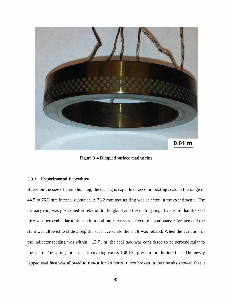
The cylindrical dimples are fabricated by an Electrox laser marking machine whose peak power is
10 kW, but the actual working power is much less than this value. Dimples are engraved into 4
rows, each containing 120 dimples per row; see Figure 3-4. The diameter of each dimple is 0.9
mm, and the depth is roughly 0.12 mm. The depth and diameter ratio (h/D) is 0.13. The center of
the first row of dimples is located at 1.2 mm away from the edge of front face. Dimpled surface
accounts for almost half of the total area, and the total area is 1.13 times larger than conventional
plane-surface ring.
42
Figure 3-4 Dimpled surface mating ring
3.3.3 Experimental Procedure
Based on the size of pump housing, the test rig is capable of accommodating seals in the range of
44.5 to 76.2 mm internal diameter. A 76.2 mm mating ring was selected in the experiments. The
primary ring was positioned in relation to the gland and the mating ring. To ensure that the seal
face was perpendicular to the shaft, a dial indicator was affixed to a stationary reference and the
stem was allowed to slide along the seal face while the shaft was rotated. When the variation of
the indicator reading was within ±12.7 µm, the seal face was considered to be perpendicular to
the shaft. The spring force of primary ring exerts 138 kPa pressure on the interface. The newly
lapped seal face was allowed to run-in for 24 hours. Once broken in, test results showed that it

43
took less than 30 minutes to reach steady state. Steady state was assumed when the interface
temperature varies less than 0.5 oC in 10 minutes and after running to 3 hours. The WebTC data
collecting system acquired data at 1 Hz, which for 3 hours of continuous testing resulted in 10,800
samples per channel.
3.4 Mating Ring Experimental Results and Discussion
Both conventional smooth ring and dimpled surface rings are used in the tests. Tests were run at
1,800 rpm and 2,700 rpm shaft rotating speed. Inlet flow rate is 1.7 gpm, fluid inlet pressure is 207
kPa, and outlet pressure is atmospheric pressure. The working fluid is discharged onto the mating
ring through a round nozzle of diameter 9 mm. This kind of impinging jet typically induces
turbulent flows at the nozzle exit [13]. The mechanical (spring) pressure is 138 KPa. The friction
coefficient between carbon graphite and stainless steel 17-4 PH was measured using the Lewis
Research LRI-1a automated tribometer. Its DC servo-motor provides 11.3 N∙m at up to 1,300 (±1)
rpm. The tests were run at 1,300 rpm under applied loads from 50 N to 120 N for 2 hours to reach
steady state. The carbon and steel parts were lubricated by the same diluted propylene glycol
solution as used in the seal tests. Figure 3-5 shows the friction coefficient as a function of applied
load. The friction coefficient strongly depends on load rather than rotating speed. The mechanical
load of our seal test rig, which is calculated based on spring force, is approximately 89 N; therefore
the friction coefficient is about 0.12. The rotating speed does affect the friction coefficient to some
extent; however, for an instant, under a certain load, the friction coefficient decreases
approximately 5% as rotating speed increases from 1,000 rpm to 1,300 rpm. The heat generation
is a function of spring force, fluid pressure, friction coefficient and rotating speed.

44
Figure 3-5 Recorded friction coefficient between 17-4PH and carbon graphite at 1,300 rpm under
different applied loads
Figure 3-6 Recorded test data at 1,800 rpm from conventional and dimpled rings
0
0.05
0.1
0.15
0.2
0.25
35 55 75 95 115 135
Fric
tio
n c
oe
ff
Applied load (N)

45
Figure 3-7 Recorded test data at 2,700 rpm from conventional and dimpled rings
Figure 3-6 is a representative case of measured interface temperature. One complete set of
temperature data of conventional ring and one set of dimpled ring, taken at the same location
(Thermocouple location #4 in Fig. 3-3), are combined in this figure to demonstrate the significant
temperature reduction capability of the dimpled ring. The interface temperature of conventional
ring is as high as 64oC at 1,800 rpm whereas for the dimpled ring it is reduced to about 58 oC. A
similar improvement is observed in Figure 3-7 when the rotating speed is increased to 2,700 rpm.
The conventional ring runs as high as 77 oC, but the dimpled ring can effectively bring the
temperature down to under 70 oC; see Tables 3-2 and 3-3. The results show that the interface
temperature can be reduced by more than 10% by using the dimpled mating ring. This has
important practical implications for high temperature industrial applications, since lower
temperature means less thermal expansions and distortions at the interface and the seals may last
longer. Further, by reducing the interface temperature to below the liquid’s flash point, one can

46
avoid surface damage. Also, the temperatures shown in Figure 3-7 demonstrate that the dimpled
surface can decrease face temperature fluctuations especially during the start-up period, which is
important to reduce the damage caused by thermal effects. Another evidence for the drop in the
interface temperature is that the average outlet and inlet fluid temperature difference of dimpled
ring is 0.1 oC higher than that of using conventional ring at the same rotating speed and flush rate.
This implies that more heat is dissipated from the seal surfaces to the working fluid or barrier fluid.
Table 3-2 Comparison of measured interface temperature at 1,800 rpm
Measurement
locations 1 2 3 4 5 6 Inlet Outlet
Conventional (oC) 61.8 61.4 63.6 64.0 63.2 62.8 40.3 40.6
Dimpled (oC) 56.2 56.5 57.1 57.8 56.8 56.9 39.2 39.6
Table 3-3 Comparison of measured interface temperature at 2,700 rpm
Measurement
locations 1 2 3 4 5 6 Inlet Outlet
Conventional (oC) 72.5 70.3 76.2 77.6 76.3 75.0 41.4 42.0
Dimpled (oC) 65.5 64.8 67.6 69.1 67.3 66.7 40.1 40.8
3.5 Dimpled Primary Ring
The textured mating ring with plain primary ring was first selected in the experimental tests. The
mating ring is stationary and there is direct flush onto its textured outer surface during the operation.
Mating ring has a larger diameter than the primary ring (76.2 mm vs. 66.6 mm) and is made of
stainless steel (17-4 PH). The textured mating ring has four rows of 120 cylindrical dimples. The
diameter of each dimple is 0.9 mm and the depth is roughly 0.12 mm. The depth-to-diameter ratio
is 0.13. Tests were run at 1800 rpm and 2700 rpm shaft rotating speed. The dimples on the primary
ring have the same diameter and depth as those on the mating ring, see Figure 3-8. To keep the
same circumferential distance between the neighboring dimples, the number of dimples on the

47
primary ring is less than that of the mating ring. There are two rows of dimples with the total
number of 200 on the primary ring (compared to four rows of total 480 dimples on the mating
ring). The primary ring is made of carbon graphite, which makes it relatively easier to fabricate
dimples on the primary ring surface than on the mating ring surface. The following is a brief
description of the experimental tests conditions: the plain mating ring is made of stainless steel
(17-4 PH), which is heat treated to have a Rockwell C hardness of 45; the working fluid is diluted
propylene glycol solution (70% in water by volume). Tests are run at 1,800 rpm and 2,700 rpm
shaft rotating speed. Inlet flow rate is 1.7 gpm, fluid inlet pressure is 207 kPa, and outlet pressure
is atmospheric pressure. The face temperatures are measured using six angularly spaced
thermocouples with different radial distance from center. The thermocouples are drilled from the
rear end of the mating ring to 0.3 mm away from the contact face. The highest measured face
temperature is near the inner diameter of the mating ring. A measurement computing WebTC
series data collecting device was connected to read thermocouples.
The test results show that the dimpled primary ring (with the conventional mating ring) can reduce
the face temperature as much as the dimpled mating ring (with the conventional primary ring).
Figures 3-9 and 10 show the comparison of the highest face temperature measured at the same
location using dimpled mating ring, dimpled primary ring and conventional ring. The dimpled
primary ring has similar temperature reduction effect as the dimpled mating ring. The dimpled
mating ring has slightly better thermal performance than dimpled primary ring at 1,800 rpm.
However, at 2,700 rpm, the dimpled primary ring has modestly better reduction capability
compared to the dimpled mating ring. For a dimpled primary ring, as the rotating speed increases,
surface shear generates more vortices and therefore enhances heat transfer. The disadvantage of
dimpled primary ring is that the contact face temperature of the dimpled primary ring fluctuates

48
more than that of dimpled mating ring, and the temperature fluctuation induces thermal stresses
on the contact face. Possible reason is that the combination of rotation and dimples leads to higher
degree of flow instability in the vicinity of the contact face of primary and mating rings.
Figure 3-8 Dimpled primary ring with treated sidewall
Note that there is a few temperature spikes (about 10 oC) using the conventional ring at high speed,
particularly near the beginning of the test. The reason for this kind of fluctuation is that, at high
speed, more interfacial heat is generated and the face temperature is higher, especially the area
close to the inner diameter due to lack of cooling. In this situation, fluid film becomes unstable as
a part of fluid film vaporizes locally and expands, then surrounding liquid phase fluid replaces
vapor and lower the interfacial temperature. This process results in the temperature fluctuation,
especially during the startup period.
dimples

49
Figure 3-9 Experimental results showing the face temperature of dimpled primary, mating and
conventional rings at 1800 rpm
Figure 3-10 Experimental results showing the face temperature of dimpled primary, mating and
conventional rings at 2700 rpm

50
3.6 Dimples on Both the Primary and Mating Rings
Experimental results show the dimples on either the stationary mating ring or the rotating primary
ring can lower the contact face temperature. However, engraving dimples on both rings results in
only slightly better temperature reduction. With a single dimpled ring, the heat generation
conducted into that ring is dramatically increased; however, with dimples on both rings, heat is
more evenly distributed into both rings. Thus, adding dimples on both seal rings cannot yield
significant temperature reduction than a single dimpled ring does.
Table 3-4 shows the contact face temperature using conventional, dimpled mating, dimpled
primary and dimpled mating and primary rings, respectively. Note that the face temperature is
deducted by the flush fluid outlet temperature, since the fluid temperature varies slightly in each
test. Cooling is slightly more effective at lower rotating speed than at higher speed.
The results indicate that the dimpled mating ring is capable of removing interfacial heat with the
added advantage of less face temperature fluctuations. The detailed estimation of the dimpled rings’
thermal performance is given as follows.
Table 3-4 Comparison of contact face temperature at 1,800 rpm and 2,700 rpm (face temperature
deducted by outlet fluid temperature) using conventional, dimpled mating, dimpled primary and
dimpled mating and primary rings
∆𝑇𝑓
Speed Conventional (oC) Dimpled mating
ring (oC)
Dimpled primary
ring (oC)
Dimples on both
rings (oC)
1,800 rpm 23.4 18.2 20.5 16.5
2,700 rpm 35.6 28.3 27.2 26.8

51
3.7 Dimpled Seal Ring Thermal Performance
3.7.1 Dimpled Mating Ring
The frictional heat generated at contact face between the rings is conducted into the primary and
mating rings. The heat distribution is often described by a heat partitioning factor. To study the
heat transfer, a simplified fin analysis can be applied to include various seal ring geometry effects
as well as to determine the heat partitioning. Luan and Khonsari [10] treated conventional seal
rings as cylindrical fin. They solved the heat distribution in the seal ring using two-dimensional
heat conduction equation and reported generalized solution for performance prediction [14]. They
also predicted the heat distribution between the primary and mating rings. Their method is used to
estimate the surface heat transfer augmentation due to dimples.
The primary rings used in those tests are conventional plain rings, and the flow inside the seal
housing is considered to be turbulent. The Nusselt number and the heat transfer coefficient around
the primary ring surface can be obtained using Eq. (1) [12]:
𝑁𝑢𝑝 = 0.028𝑃𝑟−0.038𝑅𝑒𝐷𝑝
0.875 (1)
ℎ𝑝 =
𝑁𝑢𝑝 𝐾𝑓
𝐷𝑝 (2)
The heat transfer rate through the primary ring is:
𝑞𝑝 = 𝜂ℎ𝑝 𝐴𝑝(𝑇𝑓 − 𝑇𝑜) (3)
The fin efficiency 𝜂 is estimated using Figure 3-11 plotted as a function of mL defined in Eq.
(4). It is a function of primary ring dimensions, outer surface heat transfer coefficient and
thermal conductivity, Eq. (4)

52
𝑚𝐿 = (𝐿𝑝
𝑊) √
2ℎ𝑝 𝑟𝑜𝑊
𝐾𝑝(𝑟𝑝𝑜+𝑟𝑝𝑖) (4)
Figure 3-11 Heat transfer efficiency of a primary ring [10]
The total heat generation at the contact face is a function of mechanical and fluid load, rotating
speed, and friction coefficient. A major portion of the interfacial heat is carried away by flush fluid
and small amount of heat is dissipated from the rings’ inner surface and the gland. The heat carried
away by the flush is used to calculate the overall surface heat transfer coefficient, described by Eq.
(5). The flush mass flow rate and temperature rise were measured during the tests.
𝑞𝑜𝑢𝑡 = ��𝐶𝑝(𝑇𝑜𝑢𝑡 − 𝑇𝑖𝑛) (5)
Both the conventional and dimpled mating rings are used to rub against the conventional primary
carbon ring. In both cases, the heat output from the primary ring outer surface can be calculated
using Eqs. (1) - (4) and Figure 4. Then, the heat dissipation from the conventional and dimpled

53
mating ring outer surface qm is equal to qout - qp. The calculated heat dissipation from the dimpled
ring is 1.5 times higher than that of the conventional ring at 1,800 rpm and 1.46 times higher at
2,700 rpm. Possible reason for better performance of dimpled mating ring at lower speed is that as
the rotating speed increases, the shear layer between the fluid and primary ring surface enhances
mixing around the primary ring surface and results in more heat dissipation from its surface. In
addition to the enlarged surface area (1.13 times larger than conventional ring), the change of flow
structure attributed to dimpled surface also helps to improve thermal performance of the dimpled
mating ring.
It is important to know the surface heat transfer coefficient to estimate the overall thermal
performance of the dimpled surface. Li [15] concluded that doubling the surface heat transfer
coefficient would lower the contact face temperature by 10%. The factors affecting the surface
heat transfer coefficient are surface geometry, flow characteristics, and other thermodynamics and
transport properties. Therefore, the improvement of heat transfer of the dimpled ring over
conventional ring is a result of a combination of change of surface area, heat partitioning factor
and heat transfer coefficient. In order to estimate the mating ring heat transfer coefficient, the
mating ring side-wall average surface temperature must be known. Eq. (6) can be used to calculate
the surface temperature [10],
𝑇𝑚𝑠 =𝑞𝑜𝑢𝑡
ℎ𝑚 𝐴𝑚(1+𝛾)+ 𝑇𝑜 (6)
where
𝛾 =𝑞𝑝
𝑞𝑚 , ℎ𝑚
=(0.363𝑃𝑟−0.056𝑅𝑒𝑝
0.545𝑅𝑒𝑚0.041)𝐾𝑓
𝐷𝑚 (7)

54
which is equal to 0.6 at 1,800 rpm and 0.77 at 2,700 rpm for the conventional primary and mating
ring, but for conventional primary and dimpled mating ring the values of 𝛾 reduce to 0.34 and 0.39.
A heat transfer augmentation coefficient 𝜎 is then defined, which represents the ratio of the heat
dissipation from the dimpled mating ring outer surface and from the conventional
surface, (𝑞𝑚)𝑑𝑖𝑚𝑝𝑙𝑒𝑑/(𝑞𝑚)𝑐𝑜𝑛𝑣𝑒𝑛𝑡𝑖𝑜𝑛𝑎𝑙 . The ratios are 1.5 at 1,800 rpm and 1.46 at 2,700 rpm.
This coefficient contains the effects of variation of the surface area, surface heat transfer
coefficient and the heat distribution between primary and mating rings.
Letting
𝜎 = [ℎ𝑚 𝐴𝑚(1 + 𝛾)]𝑑𝑖𝑚𝑝𝑙𝑒𝑑/[ℎ𝑚
𝐴𝑚(1 + 𝛾)]𝑐𝑜𝑛𝑣𝑒𝑛𝑡𝑖𝑜𝑛𝑎𝑙 (8)
Eq. (6) for dimpled ring becomes
𝑇𝑚𝑠 =𝑞𝑜𝑢𝑡
𝜎[ℎ𝑚 𝐴𝑚(1+𝛾)]𝑐𝑜𝑛𝑣𝑒𝑛𝑡𝑖𝑜𝑛𝑎𝑙+ 𝑇𝑜 (9)
and the dimpled mating ring outer surface overall heat transfer coefficient is calculated as
ℎ𝑚 =
𝑞𝑚
𝐴𝑚(𝑇𝑚𝑠−𝑇𝑜) (10)
The enhanced mating ring overall surface heat transfer coefficient can lower the contact face
temperature, reduce the thermal damage and prevent the working fluid flashing around the contact
face. For the current tests, the contact face temperature drops about 10%. The overall surface heat
transfer coefficient of mating ring ℎ𝑚 increase as high as 80%, at 1800 rpm and 75% at 2700 rpm.
3.7.2 Dimpled Primary Ring
As shown in Figure 3-12, the vortices generated around the circumference of the primary ring
outer surface can enhance mixing around both the primary ring outer surface and the mating ring

55
front end wall, thus increase the overall heat transfer coefficient of both rings. In this case, the
overall heat transfer coefficient of the entire seal set (The primary and mating rings can be viewed
as a pair of concentric cylinders inside the seal housing) is estimated. The contact face temperature
rise, heat output from the seal rings outer surface, thermal conductivity of primary and mating
rings and seal geometry are all known, then the overall heat transfer coefficient ℎ𝑐 can be
determined using Eq. (11) [7]. The overall heat transfer coefficient of the seal set increases 74%
at 1800 rpm and 115% at 2700 rpm.
𝑇𝑓 − 𝑇𝑜 =𝑞𝑜𝑢𝑡
𝜋𝐷𝑤√ℎ𝑐 𝑊(√𝐾𝑝+√𝐾𝑚) (11)
Figure 3-12 Dimpled primary ring on the mating ring

56
3.8 CFD Predictions
3.8.1 Modeling
The model is based on the three-dimensional configuration of the geometry and the commercial
CFD software FLUENT (ANSYS 12.1) was employed to predict the steady-state temperature and
the flow field. Included in the computational domain are the primary ring, the mating ring, the
shaft and the seal chamber. Figure 3-13 shows a schematic diagram of primary ring, mating ring
and seal chamber. Due to the complex geometry of dimpled surfaces, hybrid elements with
triangular faces are used to generate an unstructured mesh, the details of which are also shown in
the figure. The interface and the dimpled surface are meshed with fine grids to resolve the high
gradients encountered in these regions. A total of 3.74 million finite volume cells for dimpled
surface and 2.69 million cells for conventional, dimple-free surface are generated for the entire
fluid and solid domains.
Propylene glycol solution temperature is raised up less than 1 oC during the flush process, and
therefore, it is reasonable to use constant thermal conductivity (0.29 W/m∙K), constant specific
heat (3200 J/kg∙K), and constant absolute viscosity (0.0705 P), which are all estimated at 40 oC.
All computations are performed using turbulent flow, based on impinging jet flow inlet boundary
condition. The boundary condition at the outlet is set to pressure outlet. The energy equation is
solved by neglecting radiation effects. Flow is assumed to be at steady-state.
The RNG k- model is employed, which is derived using a rigorous statistical technique (called
renormalization group theory) [16]. It is a refined standard k- model known to be more accurate
and reliable for a wider class of flows than the standard k- model. As for the heat generation, an
extremely thin layer is placed between primary and mating rings as heating element, following the
method prescribed in [17]. The heat generation is a function of the pressure pm, the rotational speed

57
U, the friction coefficient of primary and mating rings f, and the interface area, and is evaluated
using the following expression.
fUApE fmp (10)
Figure 3-13 Schematic diagram of primary ring, mating ring and seal chamber
To reduce numerical errors, the second-order spatial discretization scheme is used, and the
implicit solution scheme is adopted. Discrete conservation equations (momentum, energy, etc.)
are satisfied in all cells to within a specific tolerance. Once convergence is achieved, solutions
no longer change and the balance equations are satisfied. The settings for the scaled residuals
for solution convergence are set to 10-3 for nearly all computed residuals. The only exception
is the residual for the energy equation, which is set to 10-6. Convergence is assumed to be

58
satisfied when all of the scaled residuals are less than or equal to these default settings. The
programs are run on a computer server with Intel Xeon dual core CPU (2.53 GHz) and 16 GB
memory (RAM). Generally, less than 1000 iterations are needed for convergence and take
roughly 4 hours to complete.
3.8.2 Calculation Results and Comparison
The simulation results closely match the experimental observation. An example is simulated based
on dimpled ring at 1,800 rpm. Figure 3-14 shows the numerical result of contact interface
temperature profile. The interface temperature distribution is nearly uniform except over the top
area, which is cooled by impinging jet flow. Thus, it can be concluded that at steady state, the
temperature varies in the radial and axial directions only. Figure 3-15 shows that the working fluid
flushes over the dimpled mating ring and primary ring. A secondary flow formed inside the dimple
is clearly shown in the simulation, which circulates inside the dimple, and then is bounced back to
the mainstream and mixes with outside flow. The overall heat transfer is thus enhanced due to
mixing.
Figure 3-16 shows the comparison of numerical results and the experimental results at 1,800 rpm
plotted as temperature as a function of mating ring radius. The numerical results show a similar
trend as the experimental results. However, the predicted temperatures are lower than experimental
data at the same measured point. Some factors may explain the higher temperature of experimental
results. These include factors such as estimated value of the friction coefficient, estimated spring
force and fluid pressure. Figure 3-17 demonstrates the overall heat augmentation capability using
a dimpled ring compared to a conventional ring at the different rotating speed. The Nuo is the
baseline Nusselt number, which represents the average Nusselt number of conventional ring side-

59
wall surface, while Nu is the average Nusselt number of dimpled ring on its side-wall surface. The
average Nusselt number over the dimpled mating ring’s side-wall is significantly higher than the
conventional one. Note that the Nusselt number ratios show a dependence on the primary ring’s
rotating speed. This may be attributed to flow conditions changing as Reynolds numbers of
primary ring increase.
Figure 3-14 Simulated interface temperature distribution

60
Figure 3-15 Velocity contour inside the seal chamber
Figure 3-16 Comparison of numerical and experimental results at 1,800 rpm

61
Figure 3-17 Nusselt number ratios for different rotating speed
3.9 Conclusions
Experimental measurements and CFD simulations are employed to provide evidence of the
feasibility of applying dimples in mechanical seal for the purpose of reducing a seal’s interface
temperature. Clearly, dimpled surface on the side-wall of the seal ring can enhance the heat transfer
by increasing the solid-fluid contact area and mixing. Many industrial applications utilize higher
thermal conductivity materials such as silicon carbide. The diffusion of heat is faster in such
materials than the steel used in the present experiment and the surface texture configuration can
help dissipate more heat to the working fluid. The experimental results reveal that under relatively
low fluid pressure tested, the total interface temperature is reduced by 10% by the application of
this technique. Comparisons are given for the dimples engraved on the sidewalls. Three cases of
sidewall surface texturing are considered: dimples on the mating ring, dimples on the rotating ring,

62
and dimples on both rings. The dimpled mating ring is considered to be the best solution to thermal
performance enhancement. The relationship between the surface heat transfer enhancement using
dimples and contact face temperature reduction is evaluated, and the result shows that the overall
surface heat transfer coefficient is increased about 80% using dimples. The CFD simulations
provide good agreements with experimental data and can be employed for predictions of industrial
seal applications that operate under more severe conditions involving much higher fluid pressures,
higher speeds and greater loads - all of which can result in generation of more interfacial heat.
Further attention should be given to optimization of dimples density, shapes and depth in order to
obtain best cooling effects so that this technique can be used more effectively under severe
operating conditions.
3.10 References
[1] Afanasyev, V.N., Chudnovsky, Y.P., Leontiev, A.I. and Roganov, P.S., 1993, “Turbulent flow
friction and heat transfer characteristics for spherical cavities on a flat plate,” Experimental
Thermal and Fluid Science, 7, pp. 1-8
[2] Chyu, M.K., Yu, Y., Ding, H., Downs, J.P. and Soechting, F.O., 1997, “Concavity enhanced
heat transfer in an internal cooling passage,” ASME Congress and Exposition, Orlando,
Florida
[3] Xiao, N., Zhang, Q., Ligrani, P.M. and Mongia, R., 2009, “Thermal performance of dimpled
surfaces in laminar flows,” International Journal of Heat and Mass Transfer, 52, pp. 2009-
2017
[4] Gromov, P.R., Zobnin, A.B., Rabinovich, M.I., and Sushchik, M.M., 1986, “Creation of
solitary vortices in a flow around shallow spherical depression,” Soviet Technical Physical
Letters, 12(11), pp. 1323-1328
[5] Mahmood, G.I., Hill, M.L., Nelson, D.L., Ligrani, P.M., Moon, H.K., and Glezer, B.,
2001,“Local heat transfer and flow structure on and above a dimpled surface in a channel,”
ASME Transactions-Journal of Turbomachinery, 123(1), pp: 115-123, 2001

63
[6] Moon, S.W., Lau and S.C., 2002, “Turbulent heat transfer measurements on a wall with
concave and cylindrical dimples in a square channel,” ASME Turbo Expo, Paper GT2002-
30208. pp. 459-467
[7] Lin, Y.L., Shih, TI-P, and Chyu, M.K., 1999, “Computations of flow and heat transfer in a
channel with rows of hemispherical cavities,” ASME 44th Int. Gas Turbine and Aeroengine
Congress and Exposition, Paper 99-GT-263
[8] Isaev, S.A. and Leont’ev, A.I., 2003, “Numerical simulation of vortex enhancement of heat
transfer under conditions of turbulent flow past a spherical dimple,” High Temperature, 41(5),
pp. 665-679
[9] Khalatov, A.A., Byerley, A., Ochoa, D., Min, SK and Visent, R., 2004, “Application of
advanced techniques to study fluid flow and heat transfer within and downstream a single
dimple,” Proc. of the 5th Minsk Int. Heat and Mass Transfer Forum (Minsk, Belarus, May
19-23, 2004), Inst. Heat and Mass Transfer, Minsk 2004. pp. 71-82
[10] Luan, Z.G., and Khonsari, M.M., “Heat transfer analysis in mechanical seals using fin theory,”
2007, Journal of Engineering Tribolology, 221 (6), pp. 717-725
[11] Luan, Z.G., and Khonsari, M.M., 2006, “Numerical simulations of the flow field around the
rings of mechanical seals,” Journal of Tribology, 128(3), pp. 559-565
[12] Luan, Z.G., and Khonsari, M.M., 2009, “Analysis of conjugate heat transfer and turbulent
flow in mechanical seals,” Tribology International 42(5), pp. 762-769
[13] Incropera, F.P., and DeWitt, D.P., 2001, Fundamentals of heat and mass transfer, Fifth
edition, John Wiley & Sons, NY
[14] Khonsari MM, Booser ER. Applied tribology, 2nd Ed. Wiley & Sons, West Sussex, UK.
(2008)
[15] Li CH. Thermal deformation in a mechanical face seal. ASLE trans 1968, 11, 302-309
[16] FLUENT version 6.1 User’s Manual, 2003, FLUENT, Lebanon, NH
[17] Luan, Z.G. and Khonsari, M.M., 2009, “Heat transfer correlations for laminar flows within a
mechanical seal chamber,” Tibology International 42, pp. 770-778

64
CHAPTER 4 OPTIMIZATION OF DIMPLES USING NUMERICAL METHODS
(CFD APPROACH)
4.1 Numerical (CFD) Approach and Procedures
4.1.1 Modeling
Most refineries and chemical plants produce hydrocarbons that require high pressure pumps. The
pressurized flush fluid is usually from the discharge of the pump and high fluid pressure can create
additional heat at the seal faces. Too much heat can accelerate wear rate, cause thermal distortion,
and increase the leakage rate. Given the safety requirements, the high pressure hydrocarbon tests
are not allowed in most laboratories. Therefore, numerical simulations are used to evaluate the
system performance. The CFD model allows prediction of the flow and thermal fields and provides
insights into flow structures and mechanisms. In this study a commercial software (FLUENT) is
utilized similar to that reported in [1]. Some improvements have been made in the modeling.
Instead of 𝑘 − 𝜀 model, the Reynolds stress model (RSM) is employed for treating the turbulent
flow. Reynolds stress model deals with the Reynolds-averaged Navier-Stokes equations by solving
additional transport equations for the six independent Reynolds stresses. Therefore, RSM is better
for accurately predicting complex flows, like swirl, rotation and high strain rate [2]. The non-
equilibrium wall function rather than standard wall function is used because of the complex flow
structure inside the seal housing that involves separation, reattachment, and impingement. In such
flows, the use of non-equilibrium wall function improves the CFD productions [2]. A high level
of rotation (such as primary ring in this case) introduces a large radial pressure gradient which
drives the flow in the axial and radial directions. This, in turn, determines the distribution of the
swirl or rotation in the field. A pressure interpolation scheme named PESTO (PREssure Staggering

65
Option) is substituted for the standard scheme because of its well-suited for the steep pressure
gradients involved in rotating flows [2]. Figures 6 and 7 show the meshed seal housing and the
grids of an individual dimple.
4.1.2 Comparison of Numerical and Experimental Results
The CFD simulations are compared with the previous experimental measurements and the results
are in good agreement both in trend and magnitude [1]. Figure 8 shows the comparison of
numerical (𝑘 − 𝜀 and RSM) and the experimental results of face temperature of dimpled mating
ring at the 1,800 rpm, plotted as a function of the mating ring radius. Both numerical results match
the experimental results, however, RSM provides a slightly closer results to experimental
measurement. Reynolds stress model is employed to describe the flow structure inside dimple,
dimple optimization and predict the thermal performance of dimpled surface in more severe
operating conditions in the following sections.
Figure 4-1 Computational grid of seal housing

66
Figure 4-2 Computational grids for dimples
Figure 4-3 Comparison of numerical (𝑘 − 𝜀 and RSM) and experimental results at 1,800 rpm

67
4.2 Flow Structure inside a Dimple
Arrays of dimples enhance heat transfer rate by producing vortices, which increase local, three-
dimensional turbulence transport and secondary advection downstream. Based on the existing
studies, the complex three-dimensional flows on top of a dimpled surface and within a dimple
produce a central vortex pair and an outflow region [3, 4]. This kind of structure interacts with the
bulk flow as it advects downstream, enhancing fluid mixing and surface heat transfer rates. The
flow vortices are advected to adjacent dimples after leaving one dimple. This results in a
“communication” between the nearby dimples. Zhak [5] described a variety of vortex structures
in different shaped rectangular cavities. Park et al. [6] numerically showed that centrally located
vortex pairs, as well as vortex pairs located near the spanwise edges of individual spherical dimples
increase local magnitudes of eddy diffusivity for momentum and eddy diffusivity for heat.
Limited experimental tools are available to observe the flow movement inside and in the vicinity
of a tiny dimple on a seal ring, which is directly related to the dimpled surface thermal performance.
Figure 4-4 (a)-(d) show the CFD visualization of the flow structure inside a dimple, which is useful
for understanding the mechanism of heat transfer augmentation of the dimpled ring. The dimple is
1.2 mm in diameter and 0.14 mm in depth. The flow is turbulent and an angular velocity, which
represents the rotating ring in the seal set, is added to one side of the channel. The fluid is butane
flowing at the rate of 1.7 gpm. Figure 4-4 (a) shows contours of dimensionless streamwise
velocity 𝑢 ��𝑎𝑣𝑔⁄ , which is normalized with the mean bulk flow velocity. Note that the velocity at
the top part of the figure is larger than unity because of the superposition of the bulk flow and
rotating velocities. The bulk flow velocity magnitude is large compared to the velocity within the
dimple. The low-speed streamwise flow ejected from the dimple mixes with bulk flow and results
in better mixing and heat transfer right behind the dimple’s trailing edge. The largest spanwise

68
velocity components in Figure 4-4 (b) appear within and near the dimple edge, which indicates the
secondary advection of fluid, like vortices, formed near the spanwise edge. The opposite sign of
spanwise velocity inside the dimple shows the re-circulating flow within the dimple. Figure 4-4 (c)
shows the normal velocity component. It should be noted that the relatively high magnitude of the
velocity over the flat region near the edge of the dimple corresponds to the low magnitude stream
velocity at the same locations. Figure 4-4 (d) presents the distribution of normalized streamwise
vorticity 𝜔𝑥𝐷ℎ
��𝑎𝑣𝑔⁄ in the spanwise-normal plane, where Dh is the hydraulic diameter of the
channel. It also shows that vortices are formed within the dimple and near the tailing-edge part of
the dimple rim. All the velocity components, especially Figures 4-4 (b) and (d), show the formation
of secondary flows produced near the dimple edge. The secondary flow and the resulting vortices,
enhance fluid mixing and provides better heat transfer. The vortices decay quickly into the bulk
flow. These figures also indicate that the best thermal performance occurs at the area right behind
the dimples’ trailing edge, and the area near the leading edge inside a dimple has the worst thermal
performance due to flow separation.
4.3 Optimizations of Dimples
Several studies have been reported on the dimples-related heat transfer enhancement based on
changing the depth-to-diameter ratio and dimples’ shape. Hiwada et al. [7] studied the local heat
transfer in the case of a single circular cavity in the turbulent boundary layer on a flat plate, and
they found that heat transfer is minimum for both spherical and cylindrical dimples as dimple’s
depth-to-diameter ratio is 0.2. Moon and Lau [8] demonstrated that an array of cylindrical dimples
on a flat plate provides better overall heat transfer performance and lower pressure drop than
spherical dimples of same diameter and depth.

69
(a) 𝑢
��𝑎𝑣𝑔⁄
(b) 𝑤 ��𝑎𝑣𝑔
⁄
Figure 4-4 (a) Normalized distribution of the streamwise velocity component. (b)
Normalized distribution of the spanwise velocity component. (c) Normalized distribution
of the normal velocity component. (d) Normalized distribution of the streamwise vorticity.
0.1
0.1
0.2 0.2
0.3
0.3
0.30.4
0.40.4
0.50.5
0.6 0.6
0.7 0.7
0.8 0.8 0.8
0.90.9
0.9
11
1.11.1
1.2
1.2
1.2
X
Y
-0.0
4
-0.0
4
-0.0
2
-0.02
-0.0
2
-0.02
0
0
0
0
0
0 0.0
2
0.02
0.0
2
0.0
2
0.04
0.0
4
0.0
4
0.0
6
0.0
6
0.08 0
.08
0.1
X
Y
dimple

70
(c) 𝑣��𝑎𝑣𝑔
⁄
(d) 𝜔𝑥𝐷ℎ
��𝑎𝑣𝑔⁄
-0.0
04
-0.0
03
-0.0
03
-0.003
-0.0
02
-0.002
-0.0
02
-0.0
02
-0.002
-0.0
01
-0.0
01
-0.0
01
-0.001
-0.0
01
-0.001
-0.001
-0.0
01
-0.0
01
0
0
0
00
0
0
0
0
0
0.0
01
0.0
01
0.001
0.001
0.0
01
0.0
01
0.0
01
0.001
0.00
1
0.001
0.001
0.001
0.001
0.001
0.0
02
0.0
02
0.0
02
0.0
02
0.0
02
0.0
02
0.0030.003
0.0
03
0.0
03
0.0
03
X
Y
-0.1
-0.1
-0.1
-0.1
-0.1
-0.1
-0.1
-0.1
-0.0
5
-0.0
5-0
.05
-0.05
-0.0
5
-0.0
5
-0.05
-0.0
5
-0.05
-0.0
5
-0.05
-0.05
-0.0
50.0
1
0.01
0.01
0.01
0.01
0.0
1
0.01
0.0
1
0.0
1
0.01
0.0
1
0.0
1
0.0
1
0.01
0.01
0.0
1
0.0
1
0.0
1
0.0
1
0.01
0.01
0.01
0.01
0.0
1
0.0
1
0.0
1
0.0
1
0.01
0.01
0.0
5
0.0
5
0.0
5
0.05
0.05
0.05
0.05
0.05
0.05
0.0
50.05
0.05
0.0
5
0.0
5
0.05
0.5
0.5 1
X
Y

71
The majority of published papers deal with dimples on a flat surface, and only a few of these
studies have focused on dimples on cylinder-like configuration. Kovalenko and Khalatov [9]
experimentally studied heat transfer at a dimpled tube that was in the cross-flow arrangement in a
rectangular duct. In their study, cylindrical dimples were engraved on the tube surface both in the
staggered and in-line mode. They found that the dimpled surface enhanced the heat transfer rates
up to 55% compared with a smooth tube in a confined space. Dimples on a circular seal ring should
have similar heat transfer augmentation as those on the flat plate or a tube. But the rotating flow
and relatively small size of dimples compared to the characteristic length of the seal ring and seal
housing are different from other applications. In the following CFD analysis, the focus is on the
thermal performance of a dimpled mating ring under high fluid pressure.
The liquid Butane is used as working fluid with a constant thermal conductivity 0.13 W/ (mK), a
constant specific heat 2,500 J/kg∙K, a constant dynamic viscosity 0.003 Pas, and a constant static
density 600 kg/m3. Mating ring is made of silicon carbide with the diameter of 88.9 mm (3.5 in).
The primary ring is made of carbon graphite. The balance ratio is 0.82 (for hydrocarbon, industrial
recommendation is 0.8 ~ 0.85). The rotating speed is 3,600 rpm. Liquid inlet flush rate is 3.5 gpm,
and the flush directly impinges on the half of the mating ring outer surface (rest of the mating ring
is held inside the gland). The flush area on the mating ring is less than 10 mm. The seal housing
pressure is kept at 25 MPa.
The cylindrical dimple is used since it is easy to manufacture or engrave. Its dimension is set at
1.2 mm in diameter, 600 in total, arranged in staggered fashion. The depth-to-diameter ratio ranges
from 0.11 to 0.2. Figure 4-5 shows the temperature reductions of the whole range of dimple depth
from shallow (the ratio is 0.11) to deep (the ratio equals to 0.2). The thermal performance is
generally enhanced with shallow dimples which can reduce the interface temperature by more than

72
20%. The rate of improvement in temperature reduction declines to 16% as the ratio is increased
to 0.2. This result indicates that shallow dimples perform better than deeper ones. A possible
reason is that deep dimples tend to slow down the flush fluid more than the shallow ones.
Figure 4-5 Temperature reduction as function of depth-to-diameter ratio
Figure 4-6 shows an array of dimples, where a represents the spanwise distance between two
horizontal dimples and b is the arc length corresponding to the circumferential angle between two
adjacent dimples in the same row. The depth-to-diameter ratio of three sets of staggered arranged
dimples (No. 1, 2 and 3) are fixed at 11%, and the dimple’s diameters are 0.9, 1.2 and 1.5 mm,
respectively. The spanwise spacing a is 2.5 times of dimple diameter, and streamwise spacing b
corresponds to 2.4o, 3o and 4o respectively. Based on the values of a and b, No.1, 2 and 3 rings
have six, five and four rows of dimples on the outer surface, and the total numbers are 900, 600
73
and 360. No. 4 is a set of dimples with the same diameter and streamwise spacing as No. 1, but the
spanwise spacing a is 2.8 times as dimple diameter. No. 5 is a set of dimples which are of arranged
in line, 1.2 mm in diameter. The spanwise spacing, a is 1.25 times of dimple diameter, and the
streamwise spacing b corresponds to 3o. No. 6 is a set of elliptic dimples which have a major axis
of 0.9 mm and minor axis of 0.75 mm. The depth-to-diameter (based on major axis diameter) ratio
of the elliptic dimple is the same as No.1, the spanwise spacing a and streamwise spacing b is also
as same as No. 1 and the total number is 900. The longer diameter stands in streamwise or spanwise
direction having little effect on the temperature reduction. No. 7 is the semi-spherical dimples
which have a diameter of 0.9 mm and the depth-to-diameter ratio of 11%. The spanwise spacing
a and streamwise spacing b is the same as No. 1 and the total number is 900. Table 2 shows a brief
description of different dimple configurations. The results, shown in Figure 4-7, reveals that: 1)
Staggered arrangement is better than in-line arrangement; 2) Up to a certain point, more dimples
can produce better cooling result, but the improvement is very limited. For example, the No. 2 is
definitely better than No. 3, but No. 1 and No. 2 are almost same; 3) Increasing the spanwise
spacing can slightly improve the cooling effect, since the larger spacing may provide more path
for high speed bulk flow and the vortices generated within and behind dimples need to be advected
downstream by bulk flow; and 4) The cylindrical dimples have the best thermal performance
among the considered shapes (cylindrical, elliptic and semi-spherical configurations) having the
same depth-to-diameter ratio.

74
Figure 4-6 Schematic view of dimple arrays
Table 4-1 Description of different dimple configurations
No. Descriptions
1 Cylindrical, a = 2.25 mm, b = 2.4o, staggered
2 Cylindrical, a = 3 mm, b = 3o, staggered
3 Cylindrical, a = 3.75 mm, b = 4o, staggered
4 Cylindrical, a = 2.52 mm, b = 2.4o, staggered
5 Cylindrical, a = 1.5 mm, b = 3o, in line
6 Elliptic, a = 2.25 mm, b = 2.4o, staggered
7 Semi-spherical, a = 2.25 mm, b = 2.4o, staggered
4.4 Thermal Performance Augmentation Using Dimpled Mating Rings
Figure 4-8 shows the variation of average Nusselt number with angular coordinate using a plain
ring. The distribution is different from a cylinder in cross flow. Starting at the stagnation point,
𝑁𝑢𝜃 first increases with increasing 𝜃 until about 20o. The increment may be caused by the rotation
of the primary ring. Then it declines rapidly down to about 90o as a result of the boundary layer

75
development. After that, 𝑁𝑢𝜃 is almost flat, because there is no evident wake region inside the
confined seal housing. The steady state interface temperature profile is nearly uniform for the
lower part of the contact interface. Figure 4-9 shows an example of contact face temperature of a
plain mating ring and a dimpled mating ring using No.2 dimples arrangement as described
previously. The working fluid is Butane and the fluid pressure is 25 bar. As seen, the maximum
temperature reduction is more than 40 oC.
Figure 4-7 Temperature reduction vs. different dimples arrangements
0.8 0.9 1 1.1 1.2 1.3 1.4 1.5 1.66
8
10
12
14
16
18
20
22
24
D (mm)
Te
mp
era
ture
ris
e r
ed
cu
tio
n (
%)
No.1
No.2
No.3
No.4
No.5
No.6
No.7

76
Figure 4-8 Average Nusselt number distribution as a function of angular coordinate using plain
ring
Figure 4-9 Radial interface temperature distribution at the contact face, plain and dimpled mating
ring

77
Figure 4-10 shows a schematic view of dimpled mating ring. The dimpled surface area is flushed
by working fluid, and the area without dimples is held inside the gland. Spanwise length represents
the distance from the edge of the ring front face to the end wall of the gland. As previously
discussed, the area right behind a dimple has the highest heat transfer enhancement, but area inside
the dimple and near the leading edge has the worst. Therefore, the heat transfer enhancement along
the dimpled ring spanwise length is not the same. Figure 4-11 shows that the spanwise distribution
of local Nusselt number at 20o using the plain mating ring. The sharp increase of Nusselt number
is due to the interaction of impingement working fluid with end wall of the gland. Swirling flows
are formed at that location, and dramatically increase the local heat transfer rates. Figure 4-12
shows the heat transfer augmentation using dimpled mating ring, where Nuo is the local Nusselt
number on the plain ring. The dimple size is 1.2 mm in diameter and 0.13 mm in depth. There are
600 dimples in total. The three spikes along the spanwise path are predicted right behind a dimple,
where the heat transfer rates are enhanced by the vortices and resulting flow mixing. However, it
is noted that the heat transfer rates of dimpled ring are lower than plain ring in the vicinity of the
gland wall. One possible reason is that the flow velocity experiences fluctuation over dimples and
may slow down the flush fluid at the some points which results in reducing the convective heat
transfer.
Figure 4-13 shows the spanwise distribution of local Nusselt number at 160o using plain mating
ring. The interaction between the working fluid and the end wall is weakened at this location, and
hence, the heat transfer rate is reduced. Again, there is heat transfer enhancement due to the
application of dimples as shown in Figure 4-14. Moreover, the thermal performance of dimples
close to the bottom of the ring (160o) is better than that of dimples at directly flush impinged top
area (20o), and the Nusselt number ratio is always larger than unity at the 160o. This indicates that

78
the dimples can enhance heat transfer more significantly at the locations where the plain ring has
poor heat transfer performance.
Figure 4-10 Schematic view of dimpled mating ring
Figure 4-11 Spanwise distribution of local Nusselt number at 20o using plain mating ring
0 1 2 3 4 5 6 7 8 93.1
3.15
3.2
3.25
3.3
3.35
3.4
3.45
3.5
3.55
3.6
3.65x 10
4
Length (mm)
Nu

79
Figure 4-12 Heat transfer augmentation using dimpled mating ring at 20o
Figure 4-13 Spanwise distribution of local Nusselt number at 160o using plain mating ring
0 1 2 3 4 5 6 7 8 90.85
0.9
0.95
1
1.05
1.1
1.15
1.2
1.25
Length (mm)
Nu
/ N
u0
0 1 2 3 4 5 6 7 8 91.1
1.15
1.2
1.25
1.3
1.35
x 104
Length (mm)
Nu

80
Figure 4-14 Heat transfer augmentation using dimpled mating ring at 160o
4.5 Conclusions
Mechanical face seal performance with high pressure hydrocarbon working fluid is numerically
predicted using FLUENT, a commercially available software package. The CFD simulations
yielded good agreements with experimental data conducted in the laboratory with Propylene
Glycol. Having validated the approach, the CFD simulations were employed to predict the thermal
performance of seal assembly in a process pump that utilizes a hydrocarbon liquid. These liquids
operate under more severe conditions involving high fluid pressure, high speed and high load, all
of which can result in the generation of significant interfacial heat. The dimpled mating ring, which
has rows of cylindrical engraved dimples, is used to decrease the high temperature of the primary
and mating ring interface. The dimpled mating ring shows more than 20% heat transfer
augmentation compared to the plain, untextured one. The optimal arrangement of dimples analysis
is based on the depth-to-diameter ratio, size and spacing. The best result is the shallow dimple (the
0 1 2 3 4 5 6 7 8 91
1.1
1.2
1.3
1.4
1.5
1.6
1.7
1.8
Length (mm)
Nu
/ N
u0

81
depth-to-diameter ratio is around 0.1), with relative small in size, which can increase dimples
density, and relative large in spanwise spacing, which can enhance flow mixing. The highest heat
transfer rate occurs right behind the trailing edge of a dimple. The dimpled ring can enhance heat
transfer even more at the area where conventional ring has poor thermal performance.
4.6 References
[1] Xiao, N. and Khonsari, M.M., 2012, “Thermal peroformance of mechanical seals with
textured side-wall,” Tribology International, 45(1), pp 1-7.
[2] Ansys FLUENT version 12.1 User’s Manual, 2009, FLUENT.
[3] Terekhov, V.I., Kalinina, S.V., Mshvidobadze, Y.M, 1995, “Flow structure and heat transfer
on a surface with a unit hole depression,” Russian Journal of Engineering Thermophysics,
5, pp. 11-34.
[4] Ligrani, P.M., Harrison, J.L., Mahmood, G.I. and Hill, M.L., 2001, “Flow structure due to
dimple depressions on a channel surface,” Phys. Fluids, 13(11), pp. 3442-3451.
[5] Zhak, V.D., 1995, “The Taylor-Goertler vortices and three dimensional flow evolution in a
cavity,” Russian Journal of Engineering Thermophysics, 5, pp. 165-176.
[6] Park, J., Desam, P.R, Ligrani, P.M., 2004, “Numerical predictions of flow structure above
a dimpled surface in a channel,” Numerical Heat Transfer, Part A, 45, pp.1-20.
[7] Hiwada, M., Kawamura, T., Mabuchi, M., 1983, “Some characteristic of flow pattern and
heat transfer past a circular cylindrical cavity,” Bulletin of JSME, 26(220).
[8] Moon, S.W., and Lau, S.C., “Turbulent heat transfer measurements on a wall with concave
and cylindrical dimples in a square channel, ASME Paper GT 2002-30208.
[9] Kovalenko, G.V., and Khalatov, A.A., “Fluid flow and heat transfer features at a cross-flow
of dimpled tube in confined space,” ASME Paper GT-2003-38155.

82
CHAPTER 5 THERMAL PERFORMANCE OF MECHANICAL FACE SEAL
WITH BUILT-IN HEAT PIPE3
5.1 Nomenclature
Ap – primary ring outer surface flush area (m2)
Cp – flush flow specific heat (J/kgK)
Dc – seal housing inner diameter (m)
Dh – hydraulic diameter (m)
Di – inner diameter of the heat pipe mating ring (HPMR) (m)
Do – outer diameter of the (heat pipe) mating ring (m)
Dp – outer diameter of the primary ring (m)
Dv – diameter of the vapor space inside the heat pipe (m)
Dw – median diameter between outer and inner diameter of primary ring (m)
Ep – heat generation at the interface (W)
f – friction coefficient
ℎ𝑐 – overall heat transfer coefficient of seal housing (W/ (m2
K))
ℎ𝑚 – overall heat transfer coefficient between mating ring wall and flush fluid (W/ (m2
K))
ℎ𝑝 – overall heat transfer coefficient between primary ring wall and flush fluid (W/ (m2
K))
K – thermal conductivity (W/ (mK))
Kf – thermal conductivity of flush fluid (W/ (mK))
Ki – thermal conductivity of liquid-wick combination (W/ (mK))
3 Reprinted by permission of Proc IMech E Part J: Journal of Engineering Tribology

83
Km – effective thermal conductivity of the mating ring (W/ (mK))
Kp – thermal conductivity of the carbon graphite primary ring (W/ (mK))
Kw – thermal conductivity of the stainless steel mating ring wall (W/ (mK))
Lc – condenser (heat output) length (m)
Lm – mating ring heat pipe length (m)
Lp – primary ring length (m)
�� – mass flow rate (kg/s)
ml – defined in Eq.(4)
𝑁𝑢𝑚 – overall Nusselt number around mating ring outer surface
𝑁𝑢𝑝 – overall Nusselt number around primary ring outer surface
Pr – Prandtl number
qin – heat transfer rate through the wick (condenser) (W)
qm – heat dissipation from the mating ring outer surface (W)
qout – total heat dissipation by the flush fluid (W)
qp – heat dissipation from the primary ring outer surface (W)
𝑅𝑝𝑜 − primary ring outer diameter (m)
𝑅𝑝𝑖 − primary ring inner diameter (m)
Re – Reynolds number
Tf – interface wall temperature (oC)
Tin – flush inlet temperature (oC)
To – ambient fluid temperature (oC)

84
Tout – flush outlet temperature (oC)
Tv – saturated vapor temperature (oC)
Tw(x) – mating ring wall temperature (oC)
V– flush fluid velocity (m/s)
W – contact face width (m)
𝛾 – heat partitioning factor
𝜂 – heat transfer efficiency
𝜇 – flush fluid viscosity (Pas)
𝜃 – dimensionless temperature
𝜃𝑐 – dimensionless temperature at the junction of heat output and insulated sections, defined in
Eq.(14)
𝜃𝑜 – dimensionless ambient flush temperature, defined in Eq.(11)
𝜃𝑣 – dimensionless saturated vapor temperature, defined in Eqs.(11) and (14)
𝜉 − dimensionless length coordinate for the heat output section, defined as x/L
𝜉𝑐 − dimensionless length for the heat output section, defined as Lc/L
𝜌 − flush fluid density (kg/m3)
x – axial coordinate for the heat input
5.2 Introduction
In recent years, much attention has been devoted to the study of enhancing thermal performance
of the mechanical face seal. Laser-textured face is a common approach. McNickle and Etsion [1]

85
applied laser surface texturing (LST) technique to fabricate microdimples on the seal face to form
a “near-contact” seal. They reported that at 12,000 rpm there is 40% reduction in interface friction
torque and at least 20 oC reduction in temperature using this technique. Xiao and Khonsari [2] built
a prototype of a mating ring with laser-engraved dimples on its side-wall and demonstrated that
the convective heat transfer around the seal ring was enhanced. Specially, their experimental
results and numerical predictions demonstrated that their design can reduce the interface
temperature by 10% compared to a mating ring without surface texture on its side-wall. A review
of many other innovative techniques for improving heat transfer in seals is available in a recent
article [3].
A new methodology is proposed to enhance transmission of heat away from the interface. In
general, a large portion of frictional heating generated at the interface diffuses into both seal rings
by conduction. The effectiveness of this heat removal through the primary and mating rings is
directly related to their thermal conductivity and ambient conditions. The higher the thermal
conductivity, the greater is the heat transfer into the rings by conduction. Thus, a methodology to
enhance the material thermal conductivity is highly desirable.
The approach explored in this study is to utilize the concept of heat pipe which is known for its
ability to create extremely high effective thermal conductivity. For this purpose, a mating ring with
a built-in heat pipe was designed and tested. A brief description of the design follows.
5.2.1 Heat Pipe
A typical heat pipe comprises of a sealed vacuum container with a small amount of working fluid.
It typically uses a few thin layers of wicks attached to the inside wall to transport working fluid.
Structurally, a heat pipe is composed of two major sections; see Fig. 5-1. One is an evaporator

86
section within which the working fluid is vaporized by the outside heat source (heat input). As a
result, pressure increases during vaporization and vapor flows to the low temperature end. The
second section of the heat pipe is the condenser section wherein the vapor condenses on the inner
surface of the wick and releases heat to surroundings (heat output). The working fluid then returns
to high temperature area by capillary action of the wick structure. In a conventional heat pipe, there
also exists an adiabatic section in between the evaporator and condenser sections.
A heat pipe is characterized as a device with very high effective thermal conductivity. The
increased thermal capacity results from the phase change of a working fluid. The variable
conductance heat pipe can even offer temperature control with narrow limits. Theoretically, a heat
pipe can operate in a temperature range between the working fluid triple state and the critical point.
Nevertheless, there are limitations. For example, the wick must have sufficient capillary pressure
to “pump” the fluid back to the high temperature section, vapor velocity should be subsonic and
the working fluid cannot vaporize inside the wick at the evaporator which would block the fluid
return [4].
Figure 5-1 A typical heat pipe configuration with evaporator, adiabatic and condenser sections as
described in [4]

87
The concept of heat pipe was first widely publicized in the middle of 1960s. Since then heat pipes
have been broadly used in different systems from spacecraft to electronic components for decades.
In the early days of heat pipe development, Ernst [5] provided a theoretical analysis for heat pipe
system design. Sun and Tien [6] experimentally tested a number of heat pipes with different
working fluids, heat output conditions, and lengths. The experimental results matched their
theoretical predictions. El-Nasr and El-Haggar [7] investigated the effective thermal conductivity
of the heat pipe and found that increasing the number of wick layers can increase the heat pipe
thermal conductivity and thus enhance the heat pipe ability to transfer heat. Udell [8] studied a
one-dimensional, steady-state heat transfer problem in porous media saturated with liquid and
vapor phases. The effect of gravity forces, capillarity and phase change were included in the study.
Vafai and Wang [9] reported an analysis of vapor and liquid velocity and pressure distribution for
an asymmetrical flat plate heat pipe.
A review of the open literature reveals that almost all the heat pipes used in industry are of
cylindrical geometry in tubular configuration with symmetrical heat source and sink on the side-
wall. To our knowledge, this study is the first attempt to apply the concept of heat pipe to a
mechanical face seal in order to reduce the interfacial temperature. A prototype was designed and
built wherein the heat pipe is integrated into the seal mating ring. It is important to note that this
design of the mating ring with an integrated heat pipe is different than a typical heat pipe
configuration. In this design, the mating ring face serves as the evaporator and the side-wall serves
as the condenser. The evaporator section is thus perpendicular to the condenser, and the heat pipe
length and diameter ratio is relatively short compared to the conventional heat pipes. A description
of the design and testing procedure follows.

88
5.3 Mating Ring Design and Experimental Procedure
The mating ring is made of stainless steel (17-4 PH). This material is easy to machine, has
relatively low cost, and is resistant to corrosion. Three channels are cut through from rear end of
the mating ring to 1 mm away from its front end; see Figure 5-2. The width of each channel is the
same size as that of the primary ring face to ensure that most of heat generation is absorbed by the
working liquid. Referring to Fig. 5-3A, three holes are drilled through the rear end: two for housing
the thermocouples and one for a pin. Thermocouple (TC) 1 measures the interface temperature
assuming that the interface has nearly uniform temperature. Thermocouple (TC) 2 measures the
saturated vapor temperature assuming that vapor space inside the heat pipe housing is isothermal.
After construction, the mating ring is heat treated to a hardness of 45 Rockwell C. Then, the wick
made of steel wool (an insulation material) is inserted into the housing. Fig. 5-3B illustrates the
wick material inside the housing (in practice, only a thin-layer wick attached to the outer diameter
wall is needed). Three filling holes were circumferentially drilled through the mating ring side-
wall to fill in the working fluid (water); see Fig. 5-3C. A thin copper cap was soldered to cover the
heat pipe housing opening and epoxy was used to seal the cap and to ensure that no water or vapor
escapes from it; see Fig. 5-3D. After injecting 1 ml water into each channel, the holes were tightly
sealed by screws. The mating ring is then put into a vacuum oven to lower the pressure to near
absolute zero. The filling holes are then sealed by a water-proof sealant. Finally, the mating ring’s
front end face is lapped to 1-2 helium light band.
The mating ring with the described integrated heat pipe was installed in a laboratory seal testing
rig apparatus. The primary ring used in all test is made of carbon graphite. The testing rig complies
with API standard 682. It composes of a working fluid reservoir with built-in heat exchanger, an
AMT cast iron centrifugal pump (Model no. 1626) and a seal housing. J-type thermocouples are

89
used to measure temperature and a WebTC series data collection system records the results. The
interface temperature along with the vapor and flush fluid temperatures are the primary data
measured. The interface temperature is then compared with previously measured temperature in a
conventional ring to verify the effectiveness of the built-in heat pipe. Detailed information
regarding primary and mating rings, experimental facility and test procedure are reported in [2].
Figure 5-2 Drawing of mating ring
Figure 5-3 (A) heat pipe housing (rear end view). (B) wick material placed inside heat pipe housing
(for illustration only). (C) one filling hole on the mating ring side-wall. (D) copper cap covered
mating ring rear end. (E) HPMR inside seal housing after test.

90
5.4 Results and Discussions
The primary ring is made of carbon graphite, pressed against the mating ring with a spring force
of 138 KPa. The friction coefficient between the primary ring and stainless steel measured in a
tribometer is about 0.12 [2]. The shaft rotating speeds are set to 1,800 rpm, 2,700 rpm and 3,300
rpm. The flush fluid is propylene glycol solution (70% water by volume). The flush rate is 1.7 gpm

91
and fluid inlet pressure is 207 KPa. The test conditions for the mating ring with built-in heat pipe
are identical to the conventional ring described in [2].
Experience in previous tests with the conventional mating ring [2] revealed that the interface
temperature is highest near the inner diameter because there is less convective cooling available
there compared to the outer diameter (measured as the same location as thermocouple 1 in Fig. 5-
3A. Under identical conditions, the seal’s maximum temperature in the conventional design is 64
oC at 1,800 rpm. In contrast, with the heat pipe the interface temperature of mating ring is only
47.2 oC. When the speed is increased to 2,700 rpm, the heat pipe interface temperature is 51.1 oC
whereas for the conventional ring the temperature is about 77 oC. Tables 5-1 shows ∆𝑇𝑓 which is
the interface temperature 𝑇𝑓 deducted by the working fluid outlet temperature 𝑇𝑜𝑢𝑡, since the fluid
temperature was slightly different each time. The results indicate that the heat pipe seal ring raises
the seal housing flush fluid temperature less than that experienced by the conventional mating ring
due to the significant reduction of seal face temperature. Table 5-2 shows the amount of flush fluid
temperature rise during the process. Figure 5-4 shows the interface (conventional and heat pipe)
and saturated vapor temperatures with increasing the rotational speed. Note that the conventional
seal is tested only at 1,800 and 2,700 rpm only due to the concern that at a higher speed the
temperature at the contact face may become high enough to damage the faces. Figure 5-5 shows
both the conventional and heat pipe rings’ interface temperature varies with time. The heat pipe
ring has much less temperature fluctuation than that of the conventional ring at the relative high
rotational speed, especially at start-up period. Figures 5-4 and 5 demonstrate that the heat pipe ring
can effectively reduce wear caused by thermal effects.

92
Table 5-1 Comparison of measured interface temperature at 1,800 rpm and 2,700 rpm
(interface temperature deducted by outlet fluid temperature)
∆𝑇𝑓
Speed Conventional (oC) Heat pipe (oC)
1,800 rpm 23.4 8.3
2,700 rpm 35.6 11.8
Table 5-2 Flush fluid temperature difference between inlet and outlet at 1,800 rpm and 2,700
rpm
Temperature
Speed Conventional (oC) Heat pipe (oC)
1,800 rpm 0.3 0.3
2,700 rpm 0.6 0.4
Figure 5-4 Experimental interface and vapor temperatures change with speed

93
Figure 5-5 Recorded test data at 2,700 rpm from conventional and heat pipe rings
5.5 Thermal Performance of the Heat-pipe Ring
5.5.1 The Overall Heat Transfer Performance around Heat Pipe Outer Surface
The overall heat transfer coefficient around the heat pipe ring outer surface plays an important role
in determining the seal’s thermal performance. It can be simply calculated from the heat output
divided by the surface area and the difference between the average surface temperature and the
ambient temperature. The heat generated in the friction contact face is conducted into both the
primary and mating rings in a certain proportion. Most of the heat is then dissipated from both the
primary and mating rings’ outer surfaces by convection. The heat distribution between two rings
can be determined by the materials’ thermal conductivities and the surface heat transfer
coefficients.

94
Presented by Buck [10] is a useful method for estimating seal face temperature based on the fin
equation. Luan and Khonsari [11] extended this analysis to determine face temperature and heat
partitioning factor in mechanical seals with examples for a variety of configurations [12]. Their
methods are applied to study the heat distribution between primary and mating rings.
The primary ring is a conventional seal ring made of carbon graphite and thus can be viewed as a
solid cylindrical fin. The average Nusselt number (𝑁𝑢𝑝 ) and heat transfer coefficient (ℎ𝑝
) around
the primary ring outer surface can be determined using the empirical correlations shown in Eq. (1)
and (2) [17].
𝑁𝑢𝑝 = 0.028𝑃𝑟−0.038𝑅𝑒𝐷𝑝
0.875 (1)
ℎ𝑝 =
𝑁𝑢𝑝 𝐾𝑓
𝐷𝑝 (2)
The heat dissipated from the primary ring outer surface is
𝑞𝑝 = 𝜂ℎ𝑝 𝐴𝑝(𝑇𝑓 − 𝑇𝑜) (3)
𝜂 is fin efficiency and can be obtained from Fig. 4-6 and mL for the primary ring indicates the seal
fin efficiency varies with ring’s dimensions, thermal conductivity and surface heat transfer
coefficient.
𝑚𝐿 = (𝐿𝑝
𝑊) √
2ℎ𝑝 𝑅𝑝𝑜𝑊
𝐾𝑝(𝑅𝑝𝑜+𝑅𝑝𝑖) (4)

95
Figure 5-6 Heat transfer efficiency of primary ring [11]. (Reproduce with permission)
The total heat output from both rings can be calculated from:
𝑞𝑜𝑢𝑡 = ��𝐶𝑝(𝑇𝑜𝑢𝑡 − 𝑇𝑖𝑛) (5)
The heat output from the heat pipe mating ring (HPMR) qm is equal to 𝑞𝑜𝑢𝑡 – 𝑞𝑝. The overall heat
pipe ring wall temperature can be obtained by averaging the vapor temperature and flush flow
outlet temperature. Then, the overall heat transfer coefficient around the HPMR ℎ𝑚 and the
Nusselt number 𝑁𝑢𝑚 can be estimated using the heat dissipation from the mating ring outer
surface area, temperature difference between the ring wall and the free stream fluid, fluid thermal
conductivity and ring diameter. For the conventional mating ring, the Nusselt number can be
calculated as a function of (Rep, Rem, Pr) [13],
𝑁𝑢𝑚 = 0.363𝑃𝑟−0.056𝑅𝑒𝑝
0.545𝑅𝑒𝑚0.041 (6)

96
where Rep is the Reynolds number based on the primary ring rotating velocity and primary ring
diameter; Rem is the Reynolds number based on the flush velocity and mating ring diameter.
Figure 5-7 shows the average Nusselt number around the heat pipe seal ring based on the
experimental results vs. the average Nusselt number around the conventional ring calculated from
the empirical correlations. The former is about ten times higher than the latter. This is because the
vapor condenses and releases heat right beneath the ring wall and then significantly increases the
heat flux through the ring wall.
Figure 5-7 Average Nusselt numbers of heat pipe and conventional rings
The total heat generation at the seal face is a function of friction coefficient, fluid and mechanical
pressure, primary ring rotating speed and friction area; see Eq. (7). The frictional heat is divided
between the contacting primary and mating rings. The proportion of the heat flowing into each
ring is determined assuming that the average face temperature is the same for both rings. The heat

97
partitioning factor can be defined as the ratio of the heat output from the primary ring and the
mating ring, Eq. (8).
𝐸𝑝 = 𝑓𝑃𝑉𝐴𝑓 (7)
𝛾 =𝑞𝑝
𝑞𝑚 (8)
For conventional ring 𝛾 ≈ 60% at 1,800 rpm, and reduces to 21% using heat pipe ring; at 2,700
rpm, the ratio is 77% for conventional ring vs. 25% for heat pipe ring. Basically, the HPMR is
capable of absorbing as much as twice more heat due to the phase change inside the mating ring.
5.5.2 Side-wall Temperature Distribution
The heat transfer in a heat pipe is very complex especially during the startup process, which
involves transient and multi-dimensional temperature variations. Sun and Tien [14] applied an
analytical model to predict the saturated vapor temperature, axial wall temperature, and mass flow
distribution along the heat pipe. Following their work, in this study, the temperature distribution
inside the wall is considered to be one-dimensional, steady-state heat process and is treated in a
similar fashion as the fin theory. Accordingly, the heat pipe ring is viewed as an isothermal vapor
core and an annular wall with axial heat conduction; see Figure 5-8. There are three sections inside
the heat pipe housing. The vertical interface (the seal face) serves as heat input; the wick covers
slightly more than half of the width of the mating ring whose outer surface is exposed to the flush
fluid; the rest of outer surface is held inside the gland. The outer surface inside the gland, for
simplicity, is assumed to be insulated. The inner surface is exposed to the ambient air.

98
Figure 5-8 Idealized mechanical face seal HPMR
To determine the wall temperature distribution in heat pipe ring, the following assumptions are
made:
The process is steady state;
The heat conduction of radial wall and radial liquid-wick in the evaporator are negligible
[15];
The vapor space is small, its pressure variation is neglected, and assumed to be isothermal;
The wick is fully saturated with water and convection inside the wick is negligible;
The wick and water can be treated as a homogeneous medium with uniform thermal
conductivity, with only radial temperature gradient inside the wick;
Condensation only occurs at the wick-vapor interface; and

99
The HPMR outer wall temperature varies axially. The radial temperature variation across
the wall is considered to be much less than that across the wick and between the wall and
the ambient fluid.
The conduction equation is thus simplified and the wall temperature distribution is determined
using measured test data.
The vaporization of water inside the heat pipe housing absorbs most of the heat generation at the
contact face. The saturated vapor is assumed to condense only at the interface between the wick
and vapor in the condenser section. The released heat, which is transferred to the mating ring wall
and dissipated by the flush liquid, is equal to the heat output qconv. The control volume in Figure
5-9 shows the heat transfer in the mating ring wall.
Figure 5-9 Heat transfer in the HPMR wall

100
The dqin and dqconv in Figure 5-8 are expressed in Eq. (9)
𝑑𝑞𝑖𝑛 =2𝜋𝐾𝑖(𝑇𝑤(𝑥)−𝑇𝑣)𝑑𝑥
ln (𝐷𝑖
𝐷𝑣⁄ )
, 𝑑𝑞𝑐𝑜𝑛𝑣 = ℎ𝜋𝐷0𝑑𝑥(𝑇𝑤(𝑥) − 𝑇0) (9)
The vapor temperature is constant and the wall temperature is assumed to vary only in the axial
direction. The wick layer is so thin that wick temperature is considered to vary in the radial
direction only. Thus, the heat released by condensation is characterized by one-dimensional, steady
state conduction equation in cylindrical wall. The governing equation of the wall temperature
distribution, assuming that the wall temperature varies in the axial direction alone, is as follows.
𝜋
4(𝐷0
2 − 𝐷𝑖2)𝑘𝑤
𝑑2𝑇𝑤(𝑥)
𝑑𝑥2 −2𝜋𝑘𝑖(𝑇𝑤(𝑥)−𝑇𝑣)
ln(𝐷𝑖
𝐷𝑣⁄ )
− ℎ𝜋𝐷0(𝑇𝑤(𝑥) − 𝑇𝑜) = 0 (10)
In steady state, the heat input from contact face is equal to the heat dissipated from the mating ring
outer surface,
qin = qm (11)
Let us now define the following dimensionless parameters,
𝜃(𝜉) =𝑇𝑤(𝑥)−𝑇𝑣
(𝑞𝑚/2𝜋𝐿𝑐𝑘𝑖) ln(𝐷𝑖
𝐷𝑣⁄ )
, 𝜃𝑜 =𝑇𝑜−𝑇𝑣
(𝑞𝑚/2𝜋𝐿𝑐𝑘𝑖) ln(𝐷𝑖
𝐷𝑣⁄ )
, 𝜃𝑣 = 0 (12)
Making use of Eq. (11), the dimensionless governing equation for describing the wall temperature
becomes the same as what is presented in [18]:
𝜃′′(𝜉) − 𝑀2(1 + 𝐵𝑖)𝜃(𝜉) + 𝑀2𝐵𝑖𝜃𝑜 = 0 (13)
where
d
q
c
o
n
v

101
𝑀 = [8𝑘𝑖𝐿2
𝑘𝑤(𝐷02−𝐷𝑖
2)𝑙𝑛 (𝐷𝑖
𝐷𝑣⁄ )
]
12⁄
, 𝐵𝑖 = (ℎ𝐷0
2𝑘𝑖⁄ ) 𝑙𝑛 (
𝐷𝑖𝐷𝑣
⁄ ) (14)
For the insulated section (inside the grand), the wall temperature is assumed to be same as the
vapor temperature at steady state. The temperature variation near x = 0 is considered to be very
small, and therefore the temperature gradient is negligible. Accordingly, the boundary conditions
are:
𝜃′(0) = 0, 𝜃(𝜉𝑐) = 𝜃𝑐 = 𝜃𝑣 = 0
(15)
for 0 ≪ 𝜉 ≪ 𝜉𝑐 the solution is the same as shown in [17]
𝜃(𝜉) =𝐵𝑖𝜃𝑜
1+𝐵𝑖+ (−
𝐵𝑖𝜃𝑜
1+𝐵𝑖)
cosh {𝑀(1+𝐵𝑖)12𝜉}
cosh {𝑀(1+𝐵𝑖)12𝜉𝑐}
(16)
Parameter M represents the ratio between the thermal conductivity of the liquid-wick combination
to that of the wall and the surface area to cross-sectional area. The overall heat transfer coefficient
ℎ𝑚 can be estimated using the heat output from the mating ring outer surface, the average wall
temperature which can be defined as 𝑇𝑤 = (𝑇𝑣 + 𝑇𝑜)/2, and wall outer surface flush area. Bi is the
Biot numbers with respect to wick which characterizes the radial conduction in the wick compared
to external flush convection. For Large Biot numbers, the heat rejection by convection is very
effective; for small Biot numbers, the temperature gradient in the wick is negligible.
Figure 5-10 shows the predicted axial temperature distribution along the heat output section of
mating ring at 1,800 and 2,700 rpm. Figure 5-11 shows how the dimensionless axial temperature
distribution varies as the M parameter increases. 𝑀 → ∞ represents the case of no axial
temperature variation. In present tests, M 1.3, which is small compared with conventional or

102
typical heat pipes, whose typical values range from 10 to 103 [15]. If the outer flushing area
increases or the wall thickness decreases, the M value increases, and the axial temperature variation
becomes less. But for a seal mating ring, the geometry is almost fixed and thermal conductivity of
the ring material is basically much higher than that of wick material, and thus the M value for
HPMR is small. Figure 5-12 shows the variation of dimensionless axial temperature distribution
with increasing Bi. The parameter Bi may change based on the flush fluid used in the different
applications. The flush fluid could be water, hydrocarbon or different type oils and the heat transfer
coefficients h may change from around thousands to hundreds accordingly. For small Bi number,
the wall temperature is almost uniform, but for large Bi number, the axial wall temperature change
dramatically along the heat output area. All the calculations are based on the rotating speed of
1,800 rpm. Referring to Figures. 5-11 and 12, the same trends can be seen in 2,700 rpm.
Figure 5-10 HPMR outer wall temperature distribution at the heat output section at 1,800 rpm

103
Figure 5-11 HPMR outer wall temperature variation with M at 1,800 rpm (Bi = 12)
Figure 5-12 HPMR outer wall temperature variation with Bi at 1,800 rpm (M = 1.3)

104
5.5.3 Vapor Temperature
The vapor temperature can be estimated using the wall temperature distribution. This temperature
is directly related to the operating speed. A higher rotating speed results in a rise in the heat input
and vapor temperature. At steady-state the heat input into the HPMR outer wall is equal to the heat
output, and the entire heat output from the mating ring end face and side-wall must be carried away
by the flush fluid. To model this convective heat loss, a constant overall heat transfer coefficient
ℎ is used in the calculations, assuming that the heat transfer coefficient does not change
considerably along the mating ring. The heat balance equation for the HPMR is:
𝑞𝑚 = ∫ ℎ𝑚 (𝑇𝑤(𝑥) − 𝑇0)
𝐿𝑐
0𝑑𝐴𝑠𝑖𝑑𝑒 + ℎ𝑚
(𝑇𝑤(0) − 𝑇𝑜)𝐴𝑒𝑛𝑑 (17)
where
𝑑𝐴𝑠𝑖𝑑𝑒 = 𝜋𝐷0𝑑𝑥, 𝐴𝑒𝑛𝑑 = 𝜋(𝐷0
2−𝐷𝑖2)
4 (18)
The saturated vapor temperature can be determined using the energy balance equation for the
mating ring side-wall. The heat dissipated from side-wall is equal to total heat input deducted by
the heat dissipated from the end face. To analyze, substitute Eqs. (12), (14) and (18) into Eq. (17)
and rearrange, then it can be written in the dimensionless form of as follows
∫ 𝜃(𝜉)𝑑𝜉 =𝜉𝑐
𝐵𝑖⁄
𝜉𝑐
0+ 𝜃𝑜𝜉𝑐 (19)
where
𝜃(𝜉) =𝐵𝑖𝜃𝑜
1+𝐵𝑖+ (−
𝐵𝑖𝜃𝑜
1+𝐵𝑖)
cosh {𝑀(1+𝐵𝑖)12𝜉}
cosh {𝑀(1+𝐵𝑖)12𝜉𝑐}
(16)
𝜃𝑜 =𝑇𝑜−𝑇𝑣
(𝑞𝑚/2𝜋𝐿𝑐𝑘𝑖) ln(𝐷𝑖
𝐷𝑣⁄ )
(12)

105
The parameters 𝜃𝑜 , Bi and M in Eq. (16) represent the dimensionless flush fluid temperature,
combination of heat transfer coefficient, material properties and dimensions. Since flush fluid
temperature To and heat output qm are known, the saturated vapor temperature Tv can be calculated
based on them. The calculated vapor temperature using this method is about 2% higher than the
experimentally measured value (43.4oC vs. 42.4oC at 1,800 rpm and 45.3 vs. 43.9 at 2,700 rpm).
Some factors may explain the small difference. The heat output from the end-wall may be
underestimated using ℎ noting that the end face above the primary and mating rings interface
generally has a higher heat transfer coefficient because of the high rotating speed of primary ring.
In general, however, the analytical prediction of the vapor temperature is close to the experimental
measurement. The predictions and supporting experimental measurement show that, under the
conditions simulated, these equations can be applied to determine vapor temperature in different
types of heat pipe.
5.5.4 Effective Thermal Conductivity of Heat-pipe Ring
It is well known that a heat pipe has a much higher effective thermal conductivity (as much as
several hundred times greater than that of copper [4]). In general, a thermal resistance network can
be applied to estimate the operating temperature and the effective thermal conductivity of simple
cylindrical heat pipes [15]. However, in the case of a seal ring with integrated heat pipe, the
assumed axial temperature distribution in the mating ring wall renders the problem two-
dimensional in the condenser, so that the method of thermal resistances network is not applicable.
One practical approach is to consider heat pipe ring geometry to be the same as a conventional
ring but with much higher effective thermal conductivity. In this fashion, the effective thermal
conductivity can be obtained with known face temperature, surface heat transfer coefficient, heat

106
generation and seal geometry. Bowen and Ridler [16] were the first to study the dependence of the
average temperature of sliding surfaces on the heat generation, heat transfer coefficient and
thermal conductivity. Their experiment involved a circular rod rubbing against a disc, and their
analysis was based on the contact of smooth surfaces with constant friction coefficient, with a
known overall heat transfer coefficient. According to their model, temperature rise on the friction
face is directly related to Ep and the product of the rod’s K and ℎ as follow:
𝑇𝑓 − 𝑇𝑜~𝐸𝑝
(√𝐾ℎ)𝑟𝑜𝑑
(20)
Buck [10] proposed a similar expression for seal face temperature, which includes the overall heat
transfer coefficient ℎ of the seal housing (including the primary and mating rings), and the thermal
conductivity of both primary and mating rings, Eq. (19).
𝑇𝑓 − 𝑇𝑜 =𝐸𝑝
𝜋𝐷𝑤√ℎ𝑐 𝑊(√𝐾𝑝+√𝐾𝑚) (21)
To estimate the mating ring thermal conductivity, the overall heat transfer coefficient must be
determined. The heat transfer coefficient depends on the surface geometry, fluid thermal and
transport properties. Though the primary and mating rings generally do not have the same outer
diameter, it is convenient to employ the fully developed internal flow model to approximate the
flush fluid as in a concentric tube annulus. Nau [17] used turbulent pipe flow model to predict the
seal performance in different fluids, wherein the overall heat transfer coefficient of the seal housing
can be determined by the flush fluid properties:
ℎ𝑐 ~𝜌0.8𝐶𝑝
0.4𝐾𝑓0.6/(𝜇0.4) (22)

107
Since the heat generation, face temperature, chamber overall heat transfer coefficient and primary
ring thermal conductivity are all known, the estimated effective thermal conductivity now for
current tests can be calculated using Eq. (20) and its value is about 1,200 W/ (mK), which is about
60 times higher than that of the stainless steel (17-4 PH) in the conventional ring. Details of
calculation are shown in Appendix A.
5.6 Numerical Predictions of Mechanical Seal with Built-in Heat Pipe
To verify the experimental results, a numerical model based on the three-dimensional seal
assembly is set up using the commercial CFD software FLUENT (ANSYS 14.0) to predict the
steady-state interface temperature. The simulations procedures are similar to those reported in [2],
except the Reynolds stress model (RSM) instead of 𝑘 − 𝜀 model is employed as the turbulent
model. The RSM model is believed to have better predictions of swirl or rotating flows. The mating
ring material properties, like density and specific heat, are considered as same as the pH 17-4, but
the thermal conductivity is 1,200 W/ (mK). At the operating speeds 1,800, 2,700 and 3,300 rpm,
the results showed the highest interface temperature is only 1.7 oC, 1.5 oC and 1.4 oC higher than
the experimental results.
5.6.1 Example
Let us examine the potential of using a HPMR in a high temperature (pressure) sealing application.
We restrict our attention to numerical prediction of the performance since current laboratory
settings cannot handle severe operating conditions. The seal rings are used in a hydrocarbon pump,
and the cooling flush fluid is from the discharge of the pump. Butane is the process fluid with a
constant thermal conductivity 0.13 W/ (mK), a constant specific heat 2,500 J/kg∙K, a constant
dynamic viscosity 0.003 P, and a constant static density 600 kg/m3. The primary ring is made of

108
carbon graphite. The HPMR has a thermal conductivity of 1,200 W/ (mK), and water is used as
the phase change working fluid inside the heat pipe, whose useful range is 273 K to 643 K [19].
The conventional 17-4 PH stainless steel mating ring has a thermal conductivity of 18 W/ (mK).
The balance ratio is 0.82. The rotating speed is 3,600 rpm. Liquid inlet flush rate is 3.5 gpm, and
the flush is directly impinge on the half of the mating ring outer surface (rest of the mating ring is
held inside the gland). The seal housing pressure is kept at 20 bar. The FLUENT simulation results
show that the highest interface temperature of conventional ring is 292 oC, but it is reduced to only
163 oC with heat pipe ring. Hence, the stainless steel heat pipe ring could be a good candidate in
the high temperature and pressure applications.
5.7 Conclusions
Heat removal is very important in the mechanical seal operation. Conventional cooling methods
cannot provide a direct and uniform cooling of seal interface. Thus, alternative approaches for heat
transfer augmentations are highly desirable. The experimental results on a prototype demonstrate
that much higher heat transfer efficiency using a new seal ring design with built-in heat pipe
compared to the conventional cooling methods. The heat pipe ring has the capacity of absorbing
more heat from contact face and transferring much more heat from the outer surface to flush fluid
than conventional ring. A heat conduction model is set up to describe the temperature distribution
along the mating ring side-wall and predict the saturated vapor temperature. The vapor temperature
prediction closely matches the experimental measurements. Two dimensionless parameters Bi and
M essentially determine the HPMR thermal performance. The effective thermal conductivity of
heat pipe ring is also obtained assuming the heat pipe ring has the same geometry as the
conventional ring.

109
Applying this technique significantly reduces the interface temperature and prolongs the lifespan
of mechanical seals. Moreover, constant heat input (function of mechanical and fluid pressure,
rotating speed and friction coefficient), simple geometry and high convective heat transfer
coefficient (flush) at the condenser section make the mechanical face seal with an integrated heat
pipe an excellent device for phase change technique. Because of the direct cooling of contact face,
the interface temperature would be more uniform than using external flush cooling. Hence, less
thermal distortion at the interface and resulting lower surface wear rate is expected. Further study
should focus on the optimization of mating ring heat pipe design. Careful attention must be given
to the selection of working fluid and wick material and structure for the high temperature industrial
applications.
5.8 References
[1] McNickle, A.D. and Etsion, I., 2004, “Near-contact laser surface textured dry gas seals,”
Journal of Tribology, 126, pp. 788-794.
[2] Xiao, N. and Khonsari, M.M., 2012, “Thermal performance of mechanical seals with
textured side wall,” Tribology International, 45(1), pp. 1-7.
[3] Xiao, N.and Khonsari, M.M., 2013 “A review of mechanical seals heat transfer augmentation
techniques,” Recent patents on mechanical engineering, 6(2), pp. 87-96.
[4] Dunn, P.D. and Reay, D.A., 1982, Heat pipes, 3rd ed, Pergamon Press, Oxford.
[5]. Ernst, D.M., 1967, “Evaluation of theoretical heat pipe performance,” IEEE conference
record of thermionic conversion specialist conference, Palo Alto, CA, pp. 349-354.
[6] Sun, K.H. and Tien, C.L., 1975, “Thermal performance characteristics of heat pipe,”
International Journal of Heat and Mass Transfer, 18, pp. 363-380.
[7] El-Nasr, A.A. and El-Haggar, S.M., 1996, “Effective thermal conductivity of heat pipes,”
Heat and Mass Transfer, 32, pp. 97-101.
[8] Udell, K.S., 1985, “Heat transfer in porous media considering phase change and capillarity-
the heat pipe effect,” International Journal of Heat and Mass Transfer, 28(2), pp: 485-495.

110
[9] Vafai, K. and Wang, W., 1992, “Analysis of flow and heat transfer characteristics of an
asymmetrical flat plate heat pipe,” International Journal of Heat and Mass Transfer, 35(9),
pp. 2087-2099.
[10] Buck, G.S., 1999, “Estimating heat generation, face temperature and flush rate for mechanical
seals,” Pump User Expo’99, pp. 167-172.
[11] Luan, Z.G. and Khonsari, M.M., 2007, “Heat transfer analysis in mechanical seals using fin
theory,” Journal of Engineering Tribology, 221, pp. 717-725.
[12] Khonsari, M.M. and Booser, E.R., 2008, Applied tribology, 2nd Ed, Wiley & Sons, West
Sussex, UK.
[13] Luan, Z.G. and Khonsari, M.M., 2009, “Analysis of conjugate heat transfer and turbulent
flow in mechanical seals” Tribology International, 42, pp. 762-769.
[14] Sun, K.H. and Tien, C.L., 1972, “Simple conduction model for theoretical steady-state heat
pipe performance,” AIAA Journal, 10(8), pp. 1051-1057.
[15] Bejan, A. and Kraus, A.D., 2003, Heat transfer handbook, Chap 16 Heat pipes, Wiley &
Sons, NJ.
[16] Bowden, F.P. and Ridler, K.E.W., 1936, “Physical properties of surfaces. III: The surface
temperature of sliding metals, the temperature of lubricated surfaces,” Proceedings of the
Royal Society A, 1936, 154 640-656.
[17] Nau, B.S., 1990, “Research in mechanical seals,” Proceedings of the Institute of Mechanical
Engineers, Part C: J Mechanical Engineering Science, 204(6), pp. 349-376.
[18] Incropera, F.P. and DeWitt, D.P., 2001, Fundamentals of heat and mass transfer, Chap 8
Internal flow, Fifth edition, Wiley & Sons, NY.

111
CHAPTER 6 TRIBOLOGICAL PERFORMANCE OF HEAT-PIPE RING
6.1 Introduction
Lubrication plays a crucial role in maintaining normal operation in parallel sliding components
such as thrust bearings and face seals. Over the years, considerable studies have been reported
from many different fronts to improve surface lubrication. In the past decade, surface texturing,
by means of a laser marking technique, has emerged as a popular means for enhancing performance
of tribological components. As pointed out by Etsion [1], surface texturing can serve as many tiny
reservoirs to supply lubricant to the friction surface. For the parallel sliding, textures acts as micro-
hydrodynamics bearings to provide load-carrying support and reduce wear, and they can also trap
debris during operation. Applications of dimpled-like textures on the frictional surface were
reported in [2]. Qiu and Khonsari [3] tested different micro-dimples on the stainless steel rings and
found that the textured surfaces provided low friction coefficient compared with plain surfaces.
Etsion [4] theoretically and experimentally studied the use of laser surface texturing (LST) on the
frictional surfaces, and concluded that friction, load-carrying capacity, and wear resistance were
improved with LST compared to non-textured surfaces. McNickle and Etsion [5] applied LST
technique to a seal face and reported that, at 12,000 rpm, there is 40% reduction in interface friction
torque and at least 20 oC reduction in temperature. Progress towards the improvement of
tribological performance of frictional surface by means of surface texturing can be found in Refs.
[6-8].
Compared to surface texturing, the effect of face temperature reduction on the surface lubrication
is rarely studied. Temperature related problems are frequently found in the parallel sliding
components, which can downgrade the performance of those components. For example, high

112
contact face temperature leads to lower lubricant viscosity and results in a lower load-carrying
capacity. For face seals, high face temperature may evaporate the lubricant in between the seal
ring faces and cause contact face distortion [9]. The contact face distortion may damage the flatness
of the contact face and structure of the thin lubricating film between faces. On the other hand, a
lower contact face temperature is considered to result in better lubrication, and hence, it is essential
to develop techniques that can effectively reduce contact face temperature of parallel sliding
components.
Several heat transfer improving techniques in mechanical seals can be found in a recent review
article with particular attention to available patents [10]. As reported there, Xiao and Khonsari [11]
developed a face temperature reduction technique that applies surface texturing to the side-wall of
the seal rings and reduces the face temperature by about 10%. In the more recent article by the
authors, it was demonstrated that a built-in heat pipe in the mating ring can be employed to lower
the contact face temperature between the mechanical face seal rings [12]. In fact, laboratory test
results showed a dramatic reduction in the face temperature. Both techniques, especially the built-
in heat pipe, can be used in other parallel sliding components, such as thrust bearing, to lower the
face temperature and improve surface lubrication. The relation between temperature reduction and
surface tribological performance using heat pipe technique is studied in the current work.
6.2 Heat-pipe Ring
A heat pipe comprises of a sealed vacuum container with a small amount of working fluid and
layers of wick attached to the interior wall. A typical heat pipe has two main sections: evaporator
and condenser. They are in an inline arrangement. In some cases, there is an adiabatic section in
between the evaporator and condenser. The working fluid absorbs heat and vaporizes in the

113
evaporator, and then the vapor flows to the condenser and condense back to fluid. Finally, the fluid
flows back to evaporator through porous wick layers. Generally, heat pipe has a pipe or tube like
shape, which has a symmetrical heat source and sink. Studies of asymmetrical type of heat pipe
are rarely reported. Vafai and Wang [13] showed an analysis of vapor and liquid velocity and
pressure distribution for an asymmetrical flat plate heat pipe. Xiao and Khonsari [12] designed a
mechanical face seal with built-in heat pipe, which made mating ring contact face as the evaporator
and the side-wall as the condenser. The evaporator section was thus perpendicular to the condenser
and there was an adiabatic section near the rear end of the stationary seal ring. The test results
showed that this innovative seal ring can reduce seal contact face temperature by more than 30%
[12]. The main reason of such improvement is that vaporization and condensation cycle inside the
seal ring significantly increases the ring’s overall effective thermal conductivity. As estimated in
[12], the effective thermal conductivity of the steel heat pipe seal ring is about 1200 W/ (mK),
while the thermal conductivity of same material without the heat pipe is only about 20 W/ (mK).
Easy fabrication, high heat transfer efficiency without the use of laser texturing makes heat pipe
technique ideal for frictional components. Aside from mechanical seals, this technology can be
potentially applied to other devices, such in parallel surface thrust bearings. In this chapter, a new
design and testing procedure is reported to investigate the effect of heat pipe on the tribological
performance of parallel surfaces made of stainless steel.
6.3 Design of Heat-pipe Ring
The design of the heat-pipe ring is very close to that described in [12]. Figure 6-1 shows the design
of the stationary heat-pipe ring and the rotating conventional ring. Two channels are cut through
from rear end of the heat-pipe ring to 1 mm away from its front end. The width of each channel is
almost the same size as the contact face to ensure that most of the heat generation is absorbed by

114
the working liquid (water is used here). The ring is made of stainless steel (17-4 PH), and is heat
treated to a hardness of 45 Rockwell C.
Figure 6-1. Drawing of stationary heat-pipe ring (upper) and conventional rotating ring (lower)
(units in mm)

115
Figure 6-2a shows the heat-pipe ring after heat treatment. Thin layers of wick, made of nylon fiber,
are inserted into the channels after polishing the heat-treated ring outer surface. Then, a thin copper
cap is soldered to cover the rear end of the channels and sealed by epoxy to prevent water or vapor
from leaking, Figure 6-2b. After injecting 0.5 ml water into each channel through filling holes, the
holes were tightly sealed by screws. The heat-pipe ring is then put into a vacuum oven and let the
pressure approach absolute zero. During the vacuum process, a small amount of water is pushed
out from the sealed hole with air, but water can also seal the tiny gaps between the filling holes
and screws to block the air. The filling holes are then sealed with water-proof glue. Figure 6-2c
shows the polished front end (contact face), which is lapped to 1-2 helium light band. Three
thermocouple holes are drilled through the side-wall; two in the front end for measuring the face
temperature (one near the inner diameter and another close to the outer diameter) and the third
hole for measuring the rear end temperature. The rotating ring is a conventional ring, without a
heat pipe, also made of 17-4 PH and heat treated to the same hardness of 45 Rockwell C, see Figure
6-2d.
Figure 6-2. Heat-pipe ring: (a). heat-pipe ring after heat treatment. (b). rear end of the heat-pipe
ring. (c). front end of heat-pipe ring after lapping. (d). front end of rotating ring after lapping

116
6.4 Experimental Apparatus and Procedure
The purpose of tests is to investigate the tribological performance of the heat-pipe ring compared
to that of the conventional ring. The tests are conducted using a LRI-1a universal tribometer made
by Lewis Research, Inc. Figure 6-3 shows a schematic view of the tribometer. The stationary heat-
pipe ring is placed as the lower specimen, which is connected to a friction cell to monitor friction
force. The loading system includes a lever arm, load compartment and lower specimen holder to
which the load can be added up to 2200 N (500 lbf). The upper rotating conventional ring is
attached to the spindle. The spindle speed, at current setting, can vary from 5 to 1300 rpm. There
is a ball joint to compensate the possible misalignment between upper and lower ring.
During the test, the ring contact face and rear end temperatures and the contact face friction
coefficients are the primary data measured. A WebTC series data collection system records the
results and J-type thermocouples are used to measure temperature. The WebTC data collecting
system acquired a total of 1800 data points for a 30 minutes test. The actual rotating speed and
friction coefficient (COF) are monitored and recorded by sensors and fed into a data acquisition

117
system, which is connected to a computer. The computer is programmed to send control commands
to maintain the specified operating conditions of the tribometer. A total of 150 COF data points
are collected for a 30 minutes test. The procedure for measuring face temperature and friction is
as follows. The tested rings are installed in an oil cup, then the cup is filled with SAE10 engineer
oil, which can provides lubrication and heat dissipation. There is no fluid circulation or heat
exchanger connected to the oil cup to provide additional cooling. The oil cup is air cooled by
means of an electric fan and a cooling sport towel, which can provide evaporative cooling to the
hot surface during operation. There are two pairs of specimens, one is the conventional rotating
ring against the conventional stationary ring and another is conventional rotating ring against
stationary heat-pipe ring. For the first set of tests, the rotating speed is fixed at 1100 rpm, and the
load is set to 22.25, 44.5, 89, 133.5, 178, 222.5, 267 and 311.5 N in each test. The tests are run for
heat-pipe ring pair and conventional ring pair respectively, and each test lasts for 30 minutes. For
the second test, the load is fixed at 356 N while rotating speed is changed from 1100 rpm to 500
rpm in four steps. In each step, the machine runs at a constant speed and load for 5 minutes, and
then the speed is reduced by 200 rpm. The second test is carried out only for heat-pipe ring pair.
6.5 Results and Discussions
SAE10 engine oil is used as the lubricant. Figure 6-4 shows the viscosity vs. temperature (from 20
oC to 66 oC) pertinent to SAE10 engine oil. During the test, the oil temperature tends to increase
with the rise in the ring contact face temperature. The increased face temperature changes the
lubricating oil viscosity in between the rings’ contact face and the film thickness. The friction
coefficient of the ring pair is affected by the load, lubricant viscosity and the rotating speed.

118
Figure 6-3. Schematic view of the tribometer
Figure 6-4. Viscosity of SAE10 engine oil at different temperature

119
6.5.1 Thermal Performance of Heat-pipe Ring
Figure 6-5 shows how the contact face temperature varies with increasing loads using both the
conventional and the heat-pipe ring. The rotating speed is fixed at 1100 rpm and the loading starts
at 22.25 N (5 lbf). The temperature linearly increases with loads for both cases, except the
conventional ring pair under 133.5 N (30 lbf) load. In this case, boundary lubrication (direct face
contact) occurs during the test. As a result, the contact face temperature dramatically increases and
the contact face quickly experiences wear. The measured average ring contact face roughness is
0.041 μm before the test. After the boundary contact, the value is increased to 1.58 μm. Figure 6-
6 shows the damage of the contact face. There are two possible reasons for the direct face contact.
First, the lubricating film is squeezed out from the gap between the contact faces. Second, the film
thickness might become so thin in such a way that the surface asperities heights become greater
than the lubricant thickness.
For heat-pipe ring, the test runs successfully even at the load of 311.5 N (70 lbf). Moreover, a
temperature reduction of more than 20% is observed comparing to the conventional ring under the
same load and speed. Figure 6-7 shows that, at the 133.5 N and 1100 rpm, the temperature of both
ring pairs rise as a function of time. The temperature of conventional ring contact face is close to
57 oC before the boundary contact occurs; while the contact face temperature of heat-pipe ring is
about 40 oC. The contact faces are separated by a thin film of SAE 10 engine oil. Note that the
viscosity of the oil is sensitive to temperature and lower face temperature results in higher lubricant
viscosity (see Figure 6-4). When the seal runs cooler, the lubricant viscosity is higher and a thicker
film is formed. In the case of conventional ring, the increased temperature and decreased oil
viscosity make the lubricating film thinner and eventually boundary contact occurs. Hence, it is

120
necessary to investigate the effect of temperature and viscosity on the rings tribological
performance.
Figure 6-5. Mesausred contact face temperature at different loads at 1100 rpm
Figure 6-6. Contact face damage

121
Figure 6-7. Temperature changes during the test under 133.5 N (30 lbf)
6.5.2 Tribological Performance of Heat-pipe Ring
To study the performance of a heat-pipe seal ring, we begin by examining its frictional behavior
in different lubrication regimes. A dimensionless lubrication parameter G, called the duty
parameter [14], is defined in Eq. (1). The duty parameter is commonly used in mechanical seal
applications. Plotting the friction coefficient f as a function G yields a well-known performance
curve known as the Stribeck curve.
𝐺 =𝜇𝑈∆𝑟
𝑊 (1)
where µ represents the fluid viscosity, U is the sliding speed, ∆r is the face width and W denotes
the total load. As Lebeck suggests [15], the duty parameter can be used as a measure of the severity

122
of seal in service. Low G values, which correspond to low viscosity or low sliding speed or high
load, do not favor fluid film lubrication; higher G values, associated with higher viscosity or sliding
speed or low load, are preferred. In the mixed or boundary lubrication regimes, with increasing G
values, friction coefficients decrease, indicating that viscous drag becomes significant. Figure 6-8
illustrates a typical f-G curve, where BL, ML and HL represent boundary lubrication, mixed
lubrication and hydrodynamic lubrication regimes, respectively.
Figure 6-8. Typical f-G curve
Figure 6-9 shows that the friction coefficient (f) plotted as a function of duty parameter (G) with
the conventional ring pair and heat-pipe ring pair at the different loads (for conventional pair,
varying from 22.3 N to 133.5 N (5 lbf to 30 lbf)); for heat-pipe pair, varying from 22.3 N to 311.5
N (5 lbf to 70 lbf)). In this case, G is a function of viscosity and loads, since the rotating speed is
maintained at 1100 rpm. The G value decreases as the load increases and viscosity decreases. The
friction coefficients of both pairs are high at low load (high G value) and the friction coefficient
𝑮 =𝝁𝑼∆𝒓
𝑾

123
decreases as the load increases. At the same load level, the G value of heat-pipe pair is larger than
that of the conventional pair, and the friction coefficient value of the heat-pipe pair is lower than
that of conventional pair. For the conventional ring pair, the boundary lubrication occurs at the
133.5 N. There are two points shown in the figure: one is before the boundary contact, another is
after with much higher friction coefficient. The rapid reduction in oil viscosity due to the
temperature rise and the concomitant drop in the film thickness are considered to be the main
reason for the direct contact. Figure 6-10 shows the friction coefficient for both pairs under the
133.5 N load. The conventional pair has higher friction coefficient and lower G value compared
to the heat-pipe pair. The friction coefficient of conventional pair significantly increases within
the boundary lubrication regime.
Finally, the heat-pipe pair is tested under 356 N (80 lbf) load with varying speeds. There are four
speeds, 1100, 900, 700 and 500 rpm. Each test lasts 5 minutes for each speed. The test begins at
1100 rpm and is reduced by 200 rpm down to 500 rpm. Figure 6-11 shows the temperature change
during the test. Temperature rises quickly from room temperature to more than 45 oC at 1100 rpm,
then the rising rate slows down when the speed is reduced to 900 rpm, and barely changes at 700
rpm. At 500 rpm, temperature rapidly increases due to the boundary contact. Figure 6-12 shows
the average friction coefficient at 1100, 900, 700 and 500 rpm. Figure 6-13 shows the variation of
friction coefficient with G values as rotating speed decreased from 1100 rpm to 500 rpm. At 1100
rpm, the lubrication condition is in the hydrodynamic lubrication regime. The hydrodynamic
friction starts with values high at relatively high rotating speed, but the friction coefficient
decreases with increasing temperature and decreasing oil viscosity. At 900 rpm, it is still in the
hydrodynamic lubrication regime, but starts to transit into the mixed lubrication. It can be
considered as the optimum sliding speed for minimum friction in that the friction coefficient has

124
lowest values. The decreasing rate of friction coefficient is in a slower pace as the temperature rise
slows down. When the speed is down to 700 rpm, the lubrication condition is in the mixed
lubrication regime. The friction coefficient turns higher and its values vary in a small range as the
face temperature remains almost unchanged. When the speed is lowered to 500 rpm, the G value
further decreases with lowering the speed. As a result, boundary lubrication prevails and the
friction coefficient is significantly higher.
Figure 6-9. Friction coefficient as function of G value at different loads at 1100 rpm rotating speed
G

125
Figure 6-10. Friction coefficient as function of G value at 1100 rpm rotating speed under 133.5 N
(30 lbf)
Figure 6-11. Heat-pipe ring pair’s face temperature changes during the test under 356 N (80 lbf)
and varying speeds
G

126
Figure 6-12. Heat-pipe ring pair’s average friction coefficient at different rotating speed under 356
N (80 lbf)
Figure 6-13. Heat-pipe ring pair’s friction coefficient as function of G value at different rotating
speed under 356 N (80 lbf) and varying speeds
G

127
6.6 Conclusions
A built-in heat pipe design is tested, and it is shown that it provides direct and uniform cooling by
means of phase change. This design is useful for the purpose of removing frictional heating from
the parallel ring pair contact faces and reducing friction. The current tests are based either on
increased loads at the same rotating speed or on decreased rotating speed at the same load. The
duty parameter (G) is used to determine the lubrication conditions. The frictional results are plotted
as friction vs. duty parameter (f-G). The lubrication condition is affected by the face temperature
reduction. The results show that the heat-pipe ring can effectively lower the contact face
temperature by more than 20% compared to conventional ring. Furthermore, lower face
temperature is considered to result in higher lubricant viscosity, and thus reduced friction
coefficient and increased G value. It is shown that, in contrast to conventional rings, a heat-pipe
ring can run at higher load level without entering into the boundary lubrication regime, and is thus
capable of operating with lower friction coefficient. Further study should involve the heat-pipe
ring running under higher load and speed, and focus on the optimization of heat-pipe ring design.
6.7 References
[1] Etsion, I., 2005, “State of the art in laser surface texturing,” ASME Journal of Tribology
127, pp. 248–53.
[2] Etsion, I., 2010, “Laser surface texturing and applications,” In: Nikas GK, editor. Recent
developments in wear prevention, friction and lubrication. Kerala, India: Research
Signpost, pp. 137–58.
[3] Qiu, Y. F. and Khonsari, M. M., 2011, “Experimental investigation of tribological
performance of laser textured stainless steel rings”, Tribology International, 44, pp. 635-
644.
[4] Etsion, I., 2004, “Improving tribological performance of mechanical components by laser
surface texturing,” Tribology Letters, 17(4), pp. 733-737.

128
[5] McNickle, A.D. and Etsion, I., 2004, “Near-contact laser surface textured dry gas seals,”
Journal of Tribology, 126, pp. 788-794.
[6] Brizmer, V., Kligerman, Y., Etsion, I., 2003, “A laser surface textured parallel thrust
bearing,” Tribology Transactions, 46(3), pp. 397–403.
[7] Shen, C. and Khonsari, M. M., 2013, “Effect of dimple’s internal structure on
hydrodynamic lubrication,” Tribology Letters, 52(3), pp. 415-430.
[8] Etsion, I. and Kligerman, Y., 1999, “Analytical and experimental investigation of laser-
textured mechanical seal faces,” STLE Tribology Transactions, 42(3), pp. 511–516.
[9] Li, C.H., 1968, “Thermal deformation in a mechanical face seal,” ASLE Transactions, 11,
pp. 302-309.
[10] Xiao, N. and Khonsari, M. M., 2013, “A review of mechanical seals heat transfer
augmentation techniques,” Recent patents on mechanical engineering, 6(2), pp. 87-96.
[11] Xiao, N. and Khonsari, M. M., 2012, “Thermal peroformance of mechanical seals with
textured side-wall,” Tribology International, 45(1), pp. 1-7.
[12] Xiao, N. and Khonsari, M. M., 2014, “Thermal peroformance of mechanical seals with
built-in heat pipe,” Journal of Engineering Tribology, 228(5), pp. 498-510.
[13] Vafai, K. and Wang, W., 1992, “Analysis of flow and heat transfer characteristics of an
asymmetrical flat plate heat pipe,” International Journal of Heat and Mass Transfer, 35(9),
pp. 2087-2099.
[14] Nau, B.S., 1967, “Hydrodynamic lubrication in face seals,” In Proc. 3rd Int’l. Conf. on Fluid
Sealing, BHRA, Cambridge, paper E5.
[15] Lebeck, A.O., 1991, Principles and design of mechanical face seals. John Wiley & Sons:
New York.
129
CHAPTER 7 SUMMARY AND FUTURE WORKS
7.1 Summary
In this dissertation, two innovative heat augmentation techniques, surface texturing and built-in
heat pipe, are investigated. A summary of the main results is as follows.
7.1.1 Dimpled Surface Texturing Ring
The surface texturing is engraved on the seal mating ring side-wall in the form of arrays of
cylindrical dimples.
Surface texturing is easy to make, and there is no need to modify the seal housing
arrangement or the flush plan.
Dimples increase the seal ring outer surface area and improve heat transfer. A CFD
simulation on a single dimple shows that dimple can enhance near boundary flow mixing.
The CFD simulations are also employed to predict the seal face temperature, and to
optimize the dimpled surface based on dimples depth-to-diameter ratio, size, arrangement
and shape of dimples.
Experimental studies are conducted on the seal mating ring with laser textured side-wall.
It is found that the textured surface can reduce the seal contact face temperature by 10%
compared to the conventional ring.
Experimental results show that the dimpled surface can minimize the face temperature
fluctuation especially at higher rotating speed and in the start-up period.
Calculations based on the experimental data shows that the overall seal mating ring side-
wall surface heat transfer coefficient can be increased up to 80% using dimples.
The dimples are also engraved onto the seal primary ring side-wall and obtain similar
cooling results as the dimples on the mating ring. But the combination of dimples and

130
rotation leads to higher degree of flow instability in the vicinity of the rings contact faces.
This kind of instability results in face temperature fluctuation, which can induce thermal
stress on the faces. Hence, dimpled primary ring is considered to be less practical than the
dimpled mating ring.
7.1.2 Built-in Heat-pipe Ring
The process to make a built-in heat pipe mating ring is as follow. Channels are cut through
rear end of the seal mating ring to near its front end. The wick material is inserted into the
channels and small amount of water is filled in. Then, the mating ring is tightly sealed up
and vacuumed.
Heat pipe ring can, by means of phase change, absorb the contact face frictional heat and
release the heat to surrounding flush fluid.
Experimental results show that this design significantly reduces seal rings’ interface
temperature.
Experimental results also show that the heat pipe ring provides better tribological
performance than the conventional ring due to the reduction in the face temperature.
The built-in heat pipe can dramatically increase the effective thermal conductivity of the
seal ring, which is estimated to be about 60 times higher than stainless steel.
The calculated overall surface Nusselt number of the heat pipe mating ring outer surface is
about 10 times higher than that of the conventional ring.
The heat pipe mating ring wall temperature distribution is modeled. It can be applied to
estimate vapor temperature inside the heat pipe ring.

131
7.2 Recommendation of Future Works
Surface texturing on the seal rings’ side-wall and built-in heat pipe are developed for the first time
to enhance thermal performance. A lot more research works are necessary to gain a thorough
understanding of their working mechanisms and to make further improvements. The following
recommendations are given for the future research:
Experimental tests on the dimpled mating ring under high pressure and high temperature
is recommended to verify the CFD predictions.
The current study is based on one wick material and one working fluid. Optimization of
heat pipe ring design should focus on the selection of working fluid and different wick
materials and structures.
The effects of built-in heat pipe in a rotating ring should be studied.
The built-in heat pipe application in other frictional components, such as in thrust bearings,
should be explored.
Performance of heat-pipe rings under high pressure and temperature environment needs to
be investigated.
Empirical equations for heat pipe ring thermal performance need to be developed.

132
APPENDICES
A. Calculations of the Heat-pipe Ring Effective Thermal Conductivity
The primary and mating rings can be viewed as a pair of concentric cylinders inside the seal
housing; hence, the internal flow model can be employed to solve the heat transfer problem inside
the seal housing. The hydraulic diameter of the seal housing is
𝐷ℎ = 𝐷𝑐 −(𝐷𝑜+𝐷𝑝)
2 (23)
The Reynolds number of the seal housing is
𝑅𝑒 =𝜌𝑉𝐷ℎ
𝜇 (24)
and its value is 2,650, which is greater than 2,300 (the critical value for the internal flow), therefore,
turbulent flow can be used in the calculations.
The overall heat transfer coefficient, which is based on the fluid properties, flush velocity and
hydraulic diameter, for the seal housing [17] [18] in chapter 5 is
ℎ𝑐 = 0.023𝜌0.8𝑉0.4𝐶𝑝
0.4𝐾𝑓0.6/(𝜇0.4𝐷ℎ
0.2) (25)
Note that the flush fluid temperatures for all the tests are around 40oC, and thus all the fluid
properties in Eq. (24) are estimated at 40oC. Also, the flush velocity is same for all the tests.
Therefore, Reynolds number and heat transfer coefficient for the seal housing are considered same
for different primary ring rotating speeds.
Then, Eq. (21) becomes
𝐾𝑚 = (𝐸𝑝
𝜋𝐷𝑤√ℎ𝑐 𝑊(𝑇𝑓−𝑇𝑜)− √𝐾𝑝)2 (26)
The calculated values for heat pipe ring effective thermal conductivity are 1,188, 1,203 and 1,209
W/ (mK) for 1,800, 2,700 and 3,300 rpm rotating speed.

133
B. Letters of Permission to Use Published Material
Grant of Permission
Dear Dr. Nian,
Thank you for your interest in our copyrighted material, and for requesting permission for its use.
Permission is granted for the following subject to the conditions outlined below:
Recent Patents on Mechanical Engineering
VOLUME: 6
ISSUE: 2
Review of Mechanical Seals Heat Transfer Augmentation Techniques
To be used in the following manner:
1. Bentham Science Publishers grants you the right to reproduce the material indicated above on a one-time, non-exclusive basis, solely for the purpose described. Permission must be requested separately for any future or additional use.
2. For an article, the copyright notice must be printed on the first page of article or book chapter. For figures, photographs, covers, or tables, the notice may appear with the material, in a footnote, or in the reference list.
Thank you for your patience while your request was being processed. If you wish to contact us further, please use the address below.
Sincerely,

134
AMBREEN IRSHAD Permissions & Rights Manager
Bentham Science Publishers
Email: [email protected]
URL: www.benthamscience.com
ELSEVIER LICENSE
TERMS AND CONDITIONS Jul 07, 2014
This is a License Agreement between Nian Xiao ("You") and Elsevier ("Elsevier") provided by
Copyright Clearance Center ("CCC"). The license consists of your order details, the terms and
conditions provided by Elsevier, and the payment terms and conditions. All payments must be made in full to CCC. For payment instructions, please see information listed at the bottom of this form. Supplier Elsevier Limited
The Boulevard, Langford Lane Kidlington, Oxford, OX5 1GB, UK Registered Company Number
1982084 Customer name Nian Xiao Customer address 2508 Patrick F. Taylor Hall
BATON ROUGE, LA 70803 License number 3423820621791 License date Jul 07, 2014 Licensed content publisher Elsevier Licensed content publication Tribology International Licensed content title Thermal performance of mechanical seals with textured side-wall Licensed content author Nian Xiao, M.M. Khonsari
Licensed content date January 2012 Licensed content volume number 45 Licensed content issue number
1
Number of pages 7 Start Page 1 End Page 7 Type of Use reuse in a thesis/dissertation Portion full article Format both print and electronic Are you the author of this Elsevier article?
Yes Will you be translating? No Title of your thesis/dissertation INNOVATIVE HEAT TRANSFER AUGMENTATION TECHNIQUES IN

135
MECHANICAL FACE SEAL Expected completion date Jul 2014 Estimated size (number of pages) 140 Rightslink Printable License https://s100.copyright.com/App/PrintableLicenseFrame.jsp?publisherID...
1 of 6 7/7/2014 3:37 PM
Elsevier VAT number GB 494 6272 12 Permissions price 0.00 USD
VAT/Local Sales Tax 0.00 USD / 0.00 GBP Total 0.00 USD

136
VITA
Nian Xiao was born in Beijing, China. He received Bachelor of Science from Beijing Union
University in 1996 and Master of Science from University of Utah in 2005. In August 2007, he
started to pursue his doctoral study in the Department of Mechanical Engineering of Louisiana
State University. Since then, he has been a doctoral student under the guidance of Dr. Michael M.
Khonsari, Dow Chemical Endowed Chair and Professor in the Department of Mechanical
Engineering of Louisiana State University. Nian Xiao will receive his Doctor of Philosophy degree
at the 2014 Fall Commencement.


![DEVELOPING HEAT TRANSFER AUGMENTATION IN A RIBBED ... Shoubra/Mechani… · Khan et. al., [7] investigated experimentally the forced convection heat transfer in developing region](https://img.pdfslide.us/doc/110x75/5f8d59a8f904745a65370ecf/developing-heat-transfer-augmentation-in-a-ribbed-shoubramechani-khan-et.jpg)