Embed Size (px)
Citation preview
2nd International Conference on Civil Engineering: Recent Applications and Future Challenges
ICCE2021 30 October – 2 November, Hurghada, Egypt
30 October – 2 November, Hurghada, Egypt 559
INNOVATIVE ENERGY-DISSIPATION SYSTEM FOR SELF-
CENTERING POSTTENSIONED STEEL MOMENT-RESISTING
FRAMES
Redhwan M. Algobahi1, Mohamed F.M. Fahmy2, & Mohamed Abdel-Basset Abdo3
1 Ph.D. Candidate, Civil Eng. Dept., Faculty of Eng., Assiut Univ., Assiut, Egypt E-mail: [email protected].
2 Dr, Civil Eng. Dept., Faculty of Eng., Assiut Univ., Assiut, Egypt E-mail: [email protected]. (corresponding author)
3 Professor, Civil Eng. Dept., Faculty of Eng., Assiut Univ., Assiut, Egypt E-mail: [email protected].
ABSTRACT
In existing research, the correlation between the resilience performance of the self-centering post-tensioned (SCPT) steel beam-column connections and the inelastic response of the required energy dissipation (ED) system was not addressed. For this purpose, a compact circular hollow steel tube (CHST) is proposed as a replaceable ED system. In the light of existing experimental results, a detailed three-dimensional finite element modeling (3D-FEM) was carried out to identify the response of the compact CHST under half cyclic loading. A lot of numerical work is concluded with the extraction of design charts to determine the axial strain (ΔL/L) of the ED system prior to encountering post-yield buckling. Therefore, in the numerically validated reference SCPT connection, several ED systems predesigned according to the design charts emphasized the capability of design charts to predict and control the resilient response of the connections. The optimum selection of proper inherent depth to thickness (D/t) ratio and length to depth (L/D) ratio of the CHST-ED system can increase the resilience of modern self-centering steel structures. Keywords: Resilience; Self-centering; Post-tensioning; Steel tube; Seismic; FEM.
1. INTRODUCTION Owing to the self-centering post-tensioned (SCPT) connections can maintain the original position of the structural system after strong earthquakes, many researchers suggest the SCPT system as an effective alternative solution for traditional welding moment connections in modern resilient steel structures, e.g., the moment-resisting frame (MRF) system [[1]; [2, 3]; [4], among others]. However, supplying the system with a metallic or frictional dissipation device is necessarily required for ensuring a sufficient energy dissipation of the SCPT system. Practically, the type and location of the ED system play a vital role in the fabrication, installation, and replacement of defective ED systems after a strong earthquake action. For instance, some procedures/precautions need to be taken for ensuring efficiency and replaceability of the defective ED system when it interferes with the floor slab (installing the ED system outside the top beam flange) [5-7]. In addition, an anti-symmetric hysteretic response is a result of placing the ED system on the outside of the bottom beam flange only [2]. Similarly, placing the ED system on the beam web facilitates maintenance/repair and replacement but has a negative impact on the connection hysteresis response and the energy-dissipating capacity [8]. It may be a good solution if the ED system (BRBs) is installed close to the inner surface of the beam flange [1]. It can effectively absorb the seismic input energy through the hysteresis response, at the same time, it helps to reach the defective ED components. However, installing and/or replacing ED components are still laborious.
2nd International Conference on Civil Engineering: Recent Applications and Future Challenges 2021
30 October – 2 November, Hurghada, Egypt 560
Compact circular hollow steel tube (CHST) is considered as an effective energy dissipation system substituted for the BRB-ED system [1] in earthquake-resistant frames. Compared with the BRB-ED system, bolted CHST is an easy-to-replace ED system. Its performance can be predicted and designed for SCPT connection. It is a workshop manufacturing unit with high quality and controllable manufacturing process. In existing research, there is no correspondence between the performance of the ED system and the resilience response of the SCPT connection. Therefore, the proposed CHST-ED system was addressed to emphasize that control the resilience can be realized and recognized.
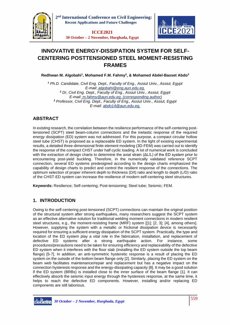
2. GENERAL ASPECTS From a practical point of view, the CHST is introduced as an ED system installed on the column
face of SCPT-MRF connections, as shown in Figs.1(a). The CHST-ED system represents a unit
in which a round HSS tube is welded to a circular end plate at each end of the HSS tube. Before
that, the circular endplate is pinched in the center, threaded, and welded to an internal nut aligned
with the threaded hole in the endplate.
Fig.1: Geometric configuration of connection with bolted CHST-ED system, (b) Installing steps of the CHST-ED system
2. NUMERICAL MODELING
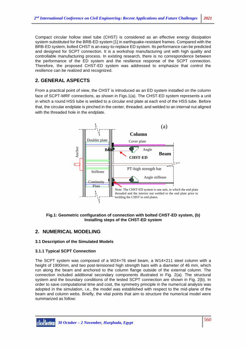
3.1 Description of the Simulated Models 3.1.1 Typical SCPT Connection The SCPT system was composed of a W24×76 steel beam, a W14×211 steel column with a height of 1900mm, and two post-tensioned high strength bars with a diameter of 46 mm, which run along the beam and anchored to the column flange outside of the external column. The connection included additional secondary components illustrated in Fig. 2(a). The structural system and the boundary conditions of the tested SCPT connection are shown in Fig. 2(b). In order to save computational time and cost, the symmetry principle in the numerical analysis was adopted in the simulation, i.e., the model was established with respect to the mid-plane of the beam and column webs. Briefly, the vital points that aim to structure the numerical model were summarized as follow:
Cover plate
Angle stiffener
CHST-ED
PT-high strength bar
An
cho
r
Column
Continuity
Plate
Stiffener
Angle Beam
Bolt
Doubler plate
Note: The CHST-ED system is one unit, in which the end plate
threaded and the interior nut welded to the end plate prior to welding the CHST to end plates.
(a)
2nd International Conference on Civil Engineering: Recent Applications and Future Challenges 2021
30 October – 2 November, Hurghada, Egypt 561
Mesh: 3D solid element (8 node linear brick elements) C3D8R (with reduced integration) is used to simulate the overall members concerning the SCPT joint configuration. Figure.2 (c) illustrates the proposed mesh for the connection members.
Interaction between Components: “tie” constraint is used to restrict any relative motion between welded parts’ surfaces as well as limit a movement of the head of the PT bars on the adjacent surfaces due to an expected high contact. For other surfaces in contact or possible contact, the normal hard contact was identified. Only for the interface between the face of the contact plate and the column face, the "penalty" friction contact is defined together with normal hard contact where the friction coefficient was 0.45 according to experimental data.
Restraints: Figure.2 (b) shows the boundary condition of the simulated model, which reflects the behavior of a frame under lateral loads. In addition, the load point is constrained in all directions except toward the load direction. Other constraints representing the symmetry condition relative to the mid-plane are defined to prohibit out-of-plane displacement and the rotations about its in-plane axes.
Fig.2: Geometric details of reference specimen [1], (a) the SCPT-ED joint, (b) analytical model and primary restraints, (c) Mesh details
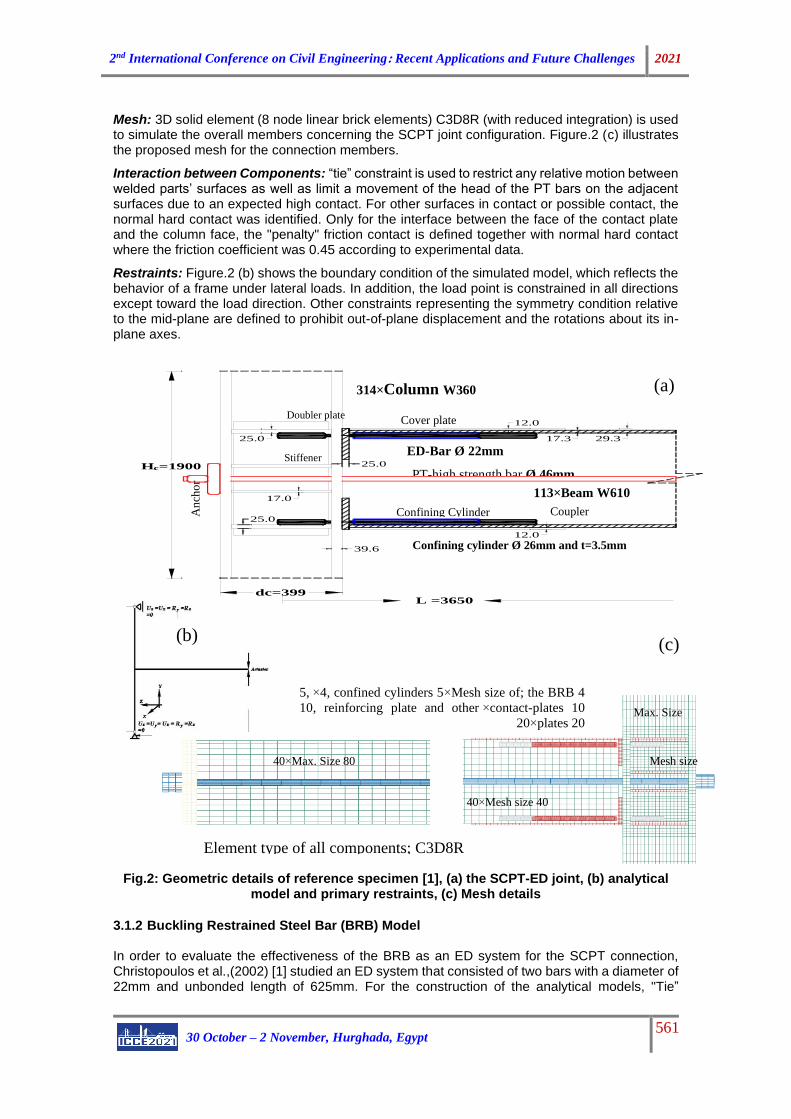
3.1.2 Buckling Restrained Steel Bar (BRB) Model In order to evaluate the effectiveness of the BRB as an ED system for the SCPT connection, Christopoulos et al.,(2002) [1] studied an ED system that consisted of two bars with a diameter of 22mm and unbonded length of 625mm. For the construction of the analytical models, "Tie”
(b)
Stiffener
12.0
17.0
dc=399
12.0
29.3
39.6
25.0
L =3650
25.0
Hc=1900
17.325.0
Cover plate
Confining Cylinder
Column W360×314
An
cho
r
Coupler
Confining cylinder Ø 26mm and t=3.5mm
Doubler plate
Beam W610×113
ED-Bar Ø 22mm
PT-high strength bar Ø 46mm
(a)
(c)
Element type of all components; C3D8R
Max. Size 80×40
Mesh size 40×40
Max. Size
60×20
Mesh size
20×20
Mesh size of; the BRB 4×4, confined cylinders 5×5,
contact-plates 10×10, reinforcing plate and other
plates 20×20
2nd International Conference on Civil Engineering: Recent Applications and Future Challenges 2021
30 October – 2 November, Hurghada, Egypt 562
constraint was defined between welds and the adjacent surfaces and between the bar and the couplers. The frictionless contact interaction was defined between the bar and the inner surface of its constrained cylinder. All degrees of freedom at both ends of the model were restricted except for the direction of the imposed cyclic load that applied at the load point. On the other hand, the out-of-plane deformations and the rotations around the in-plane axes of the plates were constrained on the plane of symmetry. 3.1.3 CHST Model The proposed CHST-ED system consists of a hollow structural steel tube with variable length and thickness for practical diameters of 50mm, 70mm, and 100mm. Each end of the CHST is welded to a prepared circular endplate. To simulate the impact of the column flange and the stiffened angle connecting the CHST to the SCPT system, a rigid plate attached to each end of the CHST-ED unit by high-strength bolts was modeled, as shown in Figs.3 (b). The general model configuration of the CHST-ED system and mesh size and type of the elements in the numerical models can be seen in Fig.3 (b).
Fig.3: Component specimens’ models, (a) The BRB-ED model, (b) The CHST-ED model 3.1.4 SCPT System with BRB and CHST-ED Systems The energy dissipation (ED) system that would be BRB or CHST-ED system can be integrated into the typical SCPT system discussed earlier. For the BRB-ED system, four BRBs with the details discussed above were integrated into the typical SCPT connection, as shown in Fig. 4. For the SCPT-ED connection components, all details discussed previously including the element types and mesh size of the typical system, BRB-ED system, and CHST-ED system are retained. 3.2 Mechanical Properties The mechanical properties of materials used can be summarized as follows; structural steel material of the beam, column, and other connection components had yield stress of 345MPa, true ultimate stress of 550MPa, and true ultimate strain of 0.196 mm/mm. On the other hand, the yield stress, true ultimate strength, and the true ultimate strain of the hardening BRB steel were 400MPa, 700MPa, and 0.0617 mm/mm, respectively. The post-tensioned bars had an ultimate strength of 1030Mpa. Compared with the BRB mechanical characteristic, the yield stress, the true
(a)
C3D8R is the element type of all
components
Coupler
Fillet welds
(b)
C3D20R is the element type for only the CHST,
and C3D8R is the element type for remaining
elements.
Circular End plate
Rigid plate
Mesh size 4×6
2nd International Conference on Civil Engineering: Recent Applications and Future Challenges 2021
30 October – 2 November, Hurghada, Egypt 563
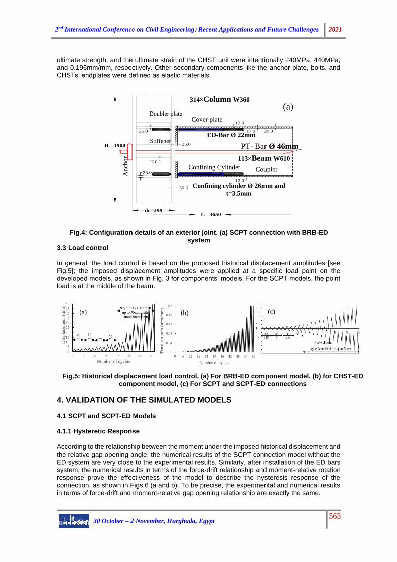
ultimate strength, and the ultimate strain of the CHST unit were intentionally 240MPa, 440MPa, and 0.196mm/mm, respectively. Other secondary components like the anchor plate, bolts, and CHSTs’ endplates were defined as elastic materials.
Fig.4: Configuration details of an exterior joint. (a) SCPT connection with BRB-ED system
3.3 Load control In general, the load control is based on the proposed historical displacement amplitudes [see Fig.5]; the imposed displacement amplitudes were applied at a specific load point on the developed models, as shown in Fig. 3 for components’ models. For the SCPT models, the point load is at the middle of the beam.
Fig.5: Historical displacement load control, (a) For BRB-ED component model, (b) for CHST-ED component model, (c) For SCPT and SCPT-ED connections
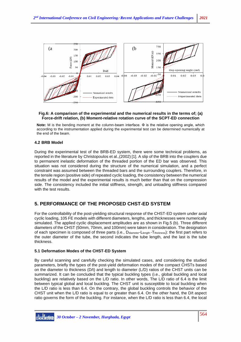
4. VALIDATION OF THE SIMULATED MODELS 4.1 SCPT and SCPT-ED Models 4.1.1 Hysteretic Response According to the relationship between the moment under the imposed historical displacement and the relative gap opening angle, the numerical results of the SCPT connection model without the ED system are very close to the experimental results. Similarly, after installation of the ED bars system, the numerical results in terms of the force-drift relationship and moment-relative rotation response prove the effectiveness of the model to describe the hysteresis response of the connection, as shown in Figs.6 (a and b). To be precise, the experimental and numerical results in terms of force-drift and moment-relative gap opening relationship are exactly the same.
(a)
Stiffener
12.0
17.0
dc=399
12.0
29.3
39.6
25.0
L =3650
25.0
Hc=1900
17.325.0
Cover plate
Confining Cylinder
Column W360× 314
An
cho
r
Coupler
Confining cylinder Ø 26mm and
t=3.5mm
Doubler plate
Beam W610× 113
ED-Bar Ø 22mm
PT- Bar Ø 46mm
(a) (c) (b)
2nd International Conference on Civil Engineering: Recent Applications and Future Challenges 2021
30 October – 2 November, Hurghada, Egypt 564
Fig.6: A comparison of the experimental and the numerical results in the terms of; (a)
Force-drift relation, (b) Moment-relative rotation curve of the SCPT-ED connection
Note: M is the bending moment at the column-beam interface. Φ is the relative opening angle, which according to the instrumentation applied during the experimental test can be determined numerically at the end of the beam.
4.2 BRB Model During the experimental test of the BRB-ED system, there were some technical problems, as reported in the literature by Christopoulos et al.,(2002) [1]. A slip of the BRB into the couplers due to permanent inelastic deformation of the threaded portion of the ED bar was observed. This situation was not considered during the structure of the numerical simulation, and a perfect constraint was assumed between the threaded bars and the surrounding couplers. Therefore, in the tensile region (positive side) of repeated cyclic loading, the consistency between the numerical results of the model and the experimental results is much better than that on the compression side. The consistency included the initial stiffness, strength, and unloading stiffness compared with the test results.
5. PERFORMANCE OF THE PROPOSED CHST-ED SYSTEM For the controllability of the post-yielding structural response of the CHST-ED system under axial cyclic loading, 105 FE models with different diameters, lengths, and thicknesses were numerically simulated. The applied cyclic displacement amplitudes are as shown in Fig.5 (b). Three different diameters of the CHST (50mm, 70mm, and 100mm) were taken in consideration. The designation of each specimen is composed of three parts (i.e., Ddiameter-Llength -Tthickness): the first part refers to the outer diameter of the tube, the second indicates the tube length, and the last is the tube thickness. 5.1 Deformation Modes of the CHST-ED System By careful scanning and carefully checking the simulated cases, and considering the studied parameters, briefly the types of the post-yield deformation modes of the compact CHSTs based on the diameter to thickness (D/t) and length to diameter (L/D) ratios of the CHST units can be summarized. It can be concluded that the typical buckling types (i.e., global buckling and local buckling) are relatively based on the L/D ratio. In other words, The L/D ratio of 6.4 is the limit between typical global and local buckling. The CHST unit is susceptible to local buckling when the L/D ratio is less than 6.4. On the contrary, the global buckling controls the behavior of the CHST unit when the L/D ratio is equal to or greater than 6.4. On the other hand, the D/t aspect ratio governs the form of the buckling. For instance, when the L/D ratio is less than 6.4, the local
(b
)
(a
)
2nd International Conference on Civil Engineering: Recent Applications and Future Challenges 2021
30 October – 2 November, Hurghada, Egypt 565
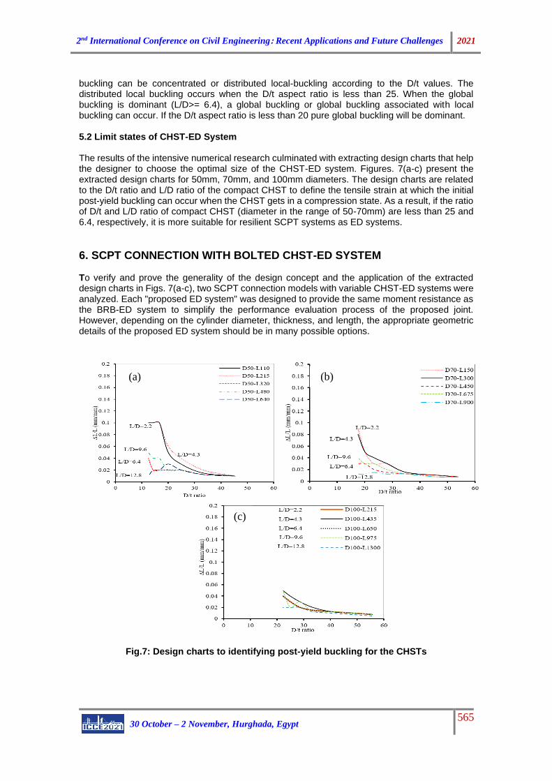
buckling can be concentrated or distributed local-buckling according to the D/t values. The distributed local buckling occurs when the D/t aspect ratio is less than 25. When the global buckling is dominant (L/D>= 6.4), a global buckling or global buckling associated with local buckling can occur. If the D/t aspect ratio is less than 20 pure global buckling will be dominant. 5.2 Limit states of CHST-ED System The results of the intensive numerical research culminated with extracting design charts that help the designer to choose the optimal size of the CHST-ED system. Figures. 7(a-c) present the extracted design charts for 50mm, 70mm, and 100mm diameters. The design charts are related to the D/t ratio and L/D ratio of the compact CHST to define the tensile strain at which the initial post-yield buckling can occur when the CHST gets in a compression state. As a result, if the ratio of D/t and L/D ratio of compact CHST (diameter in the range of 50-70mm) are less than 25 and 6.4, respectively, it is more suitable for resilient SCPT systems as ED systems.
6. SCPT CONNECTION WITH BOLTED CHST-ED SYSTEM To verify and prove the generality of the design concept and the application of the extracted design charts in Figs. 7(a-c), two SCPT connection models with variable CHST-ED systems were analyzed. Each "proposed ED system" was designed to provide the same moment resistance as the BRB-ED system to simplify the performance evaluation process of the proposed joint. However, depending on the cylinder diameter, thickness, and length, the appropriate geometric details of the proposed ED system should be in many possible options.
Fig.7: Design charts to identifying post-yield buckling for the CHSTs
(a)
(c)
(b)
2nd International Conference on Civil Engineering: Recent Applications and Future Challenges 2021
30 October – 2 November, Hurghada, Egypt 566
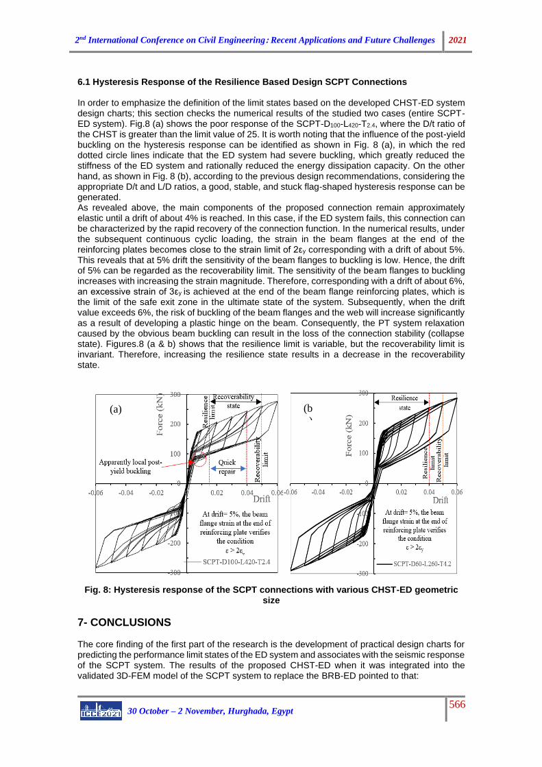
6.1 Hysteresis Response of the Resilience Based Design SCPT Connections In order to emphasize the definition of the limit states based on the developed CHST-ED system design charts; this section checks the numerical results of the studied two cases (entire SCPT-ED system). Fig.8 (a) shows the poor response of the SCPT-D100-L420-T2.4, where the D/t ratio of the CHST is greater than the limit value of 25. It is worth noting that the influence of the post-yield buckling on the hysteresis response can be identified as shown in Fig. 8 (a), in which the red dotted circle lines indicate that the ED system had severe buckling, which greatly reduced the stiffness of the ED system and rationally reduced the energy dissipation capacity. On the other hand, as shown in Fig. 8 (b), according to the previous design recommendations, considering the appropriate D/t and L/D ratios, a good, stable, and stuck flag-shaped hysteresis response can be generated. As revealed above, the main components of the proposed connection remain approximately elastic until a drift of about 4% is reached. In this case, if the ED system fails, this connection can be characterized by the rapid recovery of the connection function. In the numerical results, under the subsequent continuous cyclic loading, the strain in the beam flanges at the end of the reinforcing plates becomes close to the strain limit of 2εy corresponding with a drift of about 5%. This reveals that at 5% drift the sensitivity of the beam flanges to buckling is low. Hence, the drift of 5% can be regarded as the recoverability limit. The sensitivity of the beam flanges to buckling increases with increasing the strain magnitude. Therefore, corresponding with a drift of about 6%, an excessive strain of 3εy is achieved at the end of the beam flange reinforcing plates, which is the limit of the safe exit zone in the ultimate state of the system. Subsequently, when the drift value exceeds 6%, the risk of buckling of the beam flanges and the web will increase significantly as a result of developing a plastic hinge on the beam. Consequently, the PT system relaxation caused by the obvious beam buckling can result in the loss of the connection stability (collapse state). Figures.8 (a & b) shows that the resilience limit is variable, but the recoverability limit is invariant. Therefore, increasing the resilience state results in a decrease in the recoverability state.
Fig. 8: Hysteresis response of the SCPT connections with various CHST-ED geometric size
7- CONCLUSIONS The core finding of the first part of the research is the development of practical design charts for predicting the performance limit states of the ED system and associates with the seismic response of the SCPT system. The results of the proposed CHST-ED when it was integrated into the validated 3D-FEM model of the SCPT system to replace the BRB-ED pointed to that:
(a) (b
)
2nd International Conference on Civil Engineering: Recent Applications and Future Challenges 2021
30 October – 2 November, Hurghada, Egypt 567
• The most suitable size of the CHST to ensure the maximum drift to the resilience performance limit must have an L/D ratio < 6.4 and D/t ratio < 25.
• The proposed ED system designed according to the recommended design considerations can produce a good, stable, and stuck flag-shaped hysteresis response.
8- REFERENCES 1. Christopoulos, C., et al., Posttensioned Energy Dissipating Connections for Moment-
Resisting Steel Frames. Journal of Structural Engineering, 2002. 128(9): p. 1111-1120. 2. Chou, C.-C. and Y.-J. Lai, Post-tensioned self-centering moment connections with beam
bottom flange energy dissipators. Journal of Constructional Steel Research, 2009. 65(10): p. 1931-1941.
3. Wolski, M., J.M. Ricles, and R. Sause, Experimental Study of a Self-Centering Beam-Column Connection with Bottom Flange Friction Device. Journal of Structural Engineering, 2009. 135(5): p. 479-488.
4. Zhang, Y., et al., A performance Study of Beam Column Connections of Self-Centering Steel Frame with U-Shaped Steel dampers. Advanced Steel Construction, 2016. 12(4): p. 20.
5. Garlock, M.M., J.M. Ricles, and R. Sause, Experimental Studies of Full-Scale Posttensioned Steel Connections. Journal of Structural Engineering, 2005. 131(3): p. 438-448.
6. Kim, H.-J. and C. Christopoulos, Friction Damped Posttensioned Self-Centering Steel Moment-Resisting Frames. Journal of Structural Engineering, 2008. 134(11): p. 1768-1779.
7. Mirzaie Aliabadi, M., M.R. Bahaari, and S. Torabian, Design and Analytical Evaluation of a New Self-Centering Connection with Bolted T-Stub Devices. Advances in Materials Science and Engineering, 2013. 2013: p. 163021.
8. Zhang, A.-l., et al., Cyclic behavior of a prefabricated self-centering beam–column connection with a bolted web friction device. Engineering Structures, 2016. 111: p. 185-198.