Embed Size (px)
Citation preview
LIST OF ACRONYMS
A/C AircraftATA Air Transportation AssociationABS Acrylonitrile butadiene styreneDT keys Design time keysECS Environmental Control Systems
INTRODUCTION
One of our strategic customers has approached us in devel-One of our strategic customers has approached us in devel-oping innovative bracket design concepts for the installation of aircraft systems. Since the bracket installation zone is around the frame area (Fig. 1a, b) attached to fuselage structure, it
is necessary to know about some basic structural elements through which the routing of air ducts and cable bundles takes place. The studied zone is extended on fuselage area covering its entire sections for the application of bracket installation.
Aircraft structures
fuselage, wings, empennage (stabilizers, rudder, and eleva-
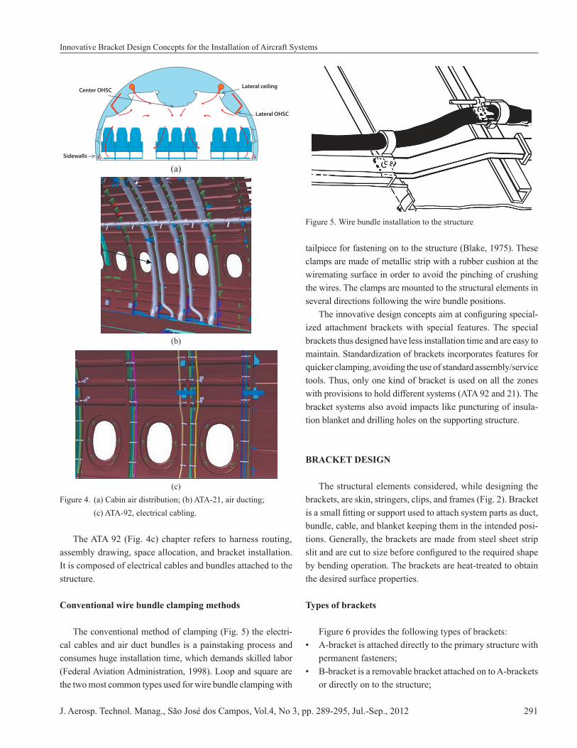
and landing gear. Among these, fuselage is an essentially tubular structure, with the forward and rear ends formed as cones. The fuselage structure is divided into vertical (frames/rings, bulkhead) and longitudinal members (longerons, string-ers), as can be seen in Fig. 2. The external skins are made from sheets, suitably formed to follow the aerodynamic shape by rolling or stretching form. They are secured to the longitudinal and transverse supporting structure by riveting. The largest single item of the fuselage structure is the skin (Fig. 3) and its stiffeners. It is also the
Innovative Bracket Design Concepts for the Installation of Aircraft SystemsAdiki Sivaiah*Infotech Enterprises Limited, Bangalore - India
Abstract:-
-
Keywords:
J. Aerosp. Technol. Manag., São José dos Campos, Vol.4, No 3, pp. 289-295, Jul.-Sep., 2012 289
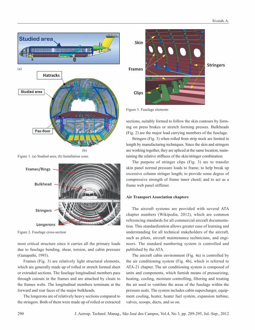
most critical structure since it carries all the primary loads due to fuselage bending, shear, torsion, and cabin pressure
Frames (Fig. 3) are relatively light structural elements, which are generally made up of rolled or stretch formed sheet or extruded sections. The fuselage longitudinal members pass through cutouts in the frames and are attached by cleats to the frames webs. The longitudinal members terminate at the forward and rear faces of the major bulkheads. The longerons are of relatively heavy sections compared to the stringers. Both of them were made up of rolled or extracted
sections, suitably formed to follow the skin contours by form-ing on press brakes or stretch forming presses. Bulkheads (Fig. 2) are the major load carrying members of the fuselage. Stringers (Fig. 3) when rolled from strip stock are limited in length by manufacturing techniques. Since the skin and stringers are working together, they are spliced at the same location, main-taining the relative stiffness of the skin/stringer combination. The purpose of stringer clips (Fig. 3) are to transfer skin panel normal pressure loads to frame; to help break up excessive column stringer length; to provide some degree of compressive strength of frame inner chord; and to act as a frame web panel stiffener.
Air Transport Association chapters
The aircraft systems are provided with several ATA
referencing standards for all commercial aircraft documenta-tion. This standardization allows greater ease of learning and understanding for all technical stakeholders of the aircraft, such as pilots, aircraft maintenance technicians, and engi-neers. The standard numbering system is controlled and published by the ATA.
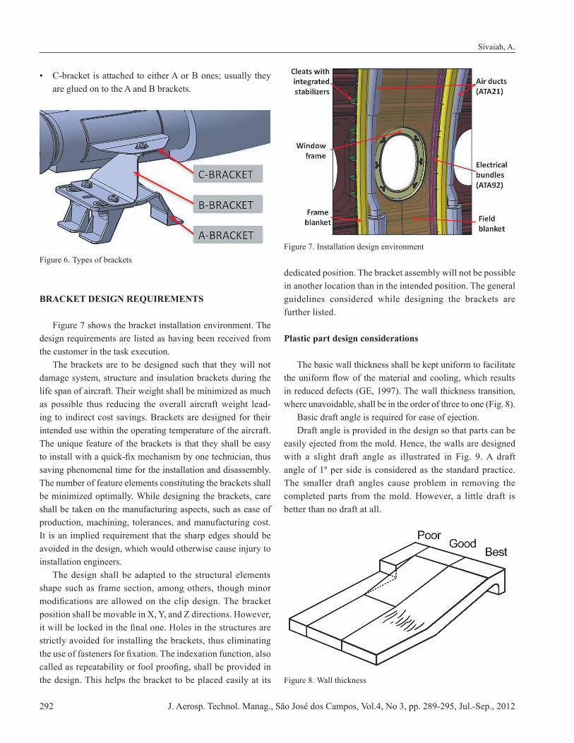
ATA-21 chapter. The air conditioning system is composed of units and components, which furnish means of pressurizing,
the air used to ventilate the areas of the fuselage within the pressure seals. The system includes cabin supercharger, equip-ment cooling, heater, heater fuel system, expansion turbine, valves, scoops, ducts, and so on.
Sivaiah, A.
Figure 3. Fuselage elements
(a)
(b)Figure 1. (a) Studied area; (b) Installation zone.
Figure 2. Fuselage cross-section
J. Aerosp. Technol. Manag., São José dos Campos, Vol.4, No 3, pp. 289-295, Jul.-Sep., 2012290
assembly drawing, space allocation, and bracket installation. It is composed of electrical cables and bundles attached to the structure.
Conventional wire bundle clamping methods
-cal cables and air duct bundles is a painstaking process and consumes huge installation time, which demands skilled labor
the two most common types used for wire bundle clamping with
clamps are made of metallic strip with a rubber cushion at the wiremating surface in order to avoid the pinching of crushing the wires. The clamps are mounted to the structural elements in several directions following the wire bundle positions.
-ized attachment brackets with special features. The special brackets thus designed have less installation time and are easy to maintain. Standardization of brackets incorporates features for quicker clamping, avoiding the use of standard assembly/service tools. Thus, only one kind of bracket is used on all the zones
bracket systems also avoid impacts like puncturing of insula-tion blanket and drilling holes on the supporting structure.
BRACKET DESIGN
The structural elements considered, while designing the brackets, are skin, stringers, clips, and frames (Fig. 2). Bracket
bundle, cable, and blanket keeping them in the intended posi-tions. Generally, the brackets are made from steel sheet strip
by bending operation. The brackets are heat-treated to obtain the desired surface properties.
Types of brackets
permanent fasteners;
or directly on to the structure;
Innovative Bracket Design Concepts for the Installation of Aircraft Systems
Center OHSCLateral ceiling
Lateral OHSC
Sidewalls
(a)
(b)
(c)
J. Aerosp. Technol. Manag., São José dos Campos, Vol.4, No 3, pp. 289-295, Jul.-Sep., 2012 291
are glued on to the A and B brackets.
BRACKET DESIGN REQUIREMENTS
design requirements are listed as having been received from the customer in the task execution. The brackets are to be designed such that they will not damage system, structure and insulation brackets during the life span of aircraft. Their weight shall be minimized as much as possible thus reducing the overall aircraft weight lead-ing to indirect cost savings. Brackets are designed for their intended use within the operating temperature of the aircraft. The unique feature of the brackets is that they shall be easy
saving phenomenal time for the installation and disassembly. The number of feature elements constituting the brackets shall be minimized optimally. While designing the brackets, care shall be taken on the manufacturing aspects, such as ease of production, machining, tolerances, and manufacturing cost. It is an implied requirement that the sharp edges should be avoided in the design, which would otherwise cause injury to installation engineers. The design shall be adapted to the structural elements shape such as frame section, among others, though minor
strictly avoided for installing the brackets, thus eliminating
the design. This helps the bracket to be placed easily at its
dedicated position. The bracket assembly will not be possible in another location than in the intended position. The general guidelines considered while designing the brackets are further listed.
Plastic part design considerations
The basic wall thickness shall be kept uniform to facilitate
Basic draft angle is required for ease of ejection. Draft angle is provided in the design so that parts can be easily ejected from the mold. Hence, the walls are designed
angle of 1º per side is considered as the standard practice. The smaller draft angles cause problem in removing the completed parts from the mold. However, a little draft is better than no draft at all.
Sivaiah, A.
J. Aerosp. Technol. Manag., São José dos Campos, Vol.4, No 3, pp. 289-295, Jul.-Sep., 2012292
Corners shall be rounded to reduce stress concentrations and fracture. Inner radius should be of at least the thickness of the walls. Add ribs for structural support, instead of increasing the
the walls to which they are attached. Their height should be less than three times the wall thickness.
main wall thickness. Bosses should be supported by ribs that
External undercuts require side cores that are added to the tooling cost, some simple can be molded by relocating the parting line.
Threading features in the brackets were not allowed
INSULATION BLANKET REQUIREMENTS
The bracket should never disturb the frame blanket posi-
compression zones are minimized in the design not exceeding
must be respected. However, holes and cutouts in the blanket are accepted if they are completely sealed.
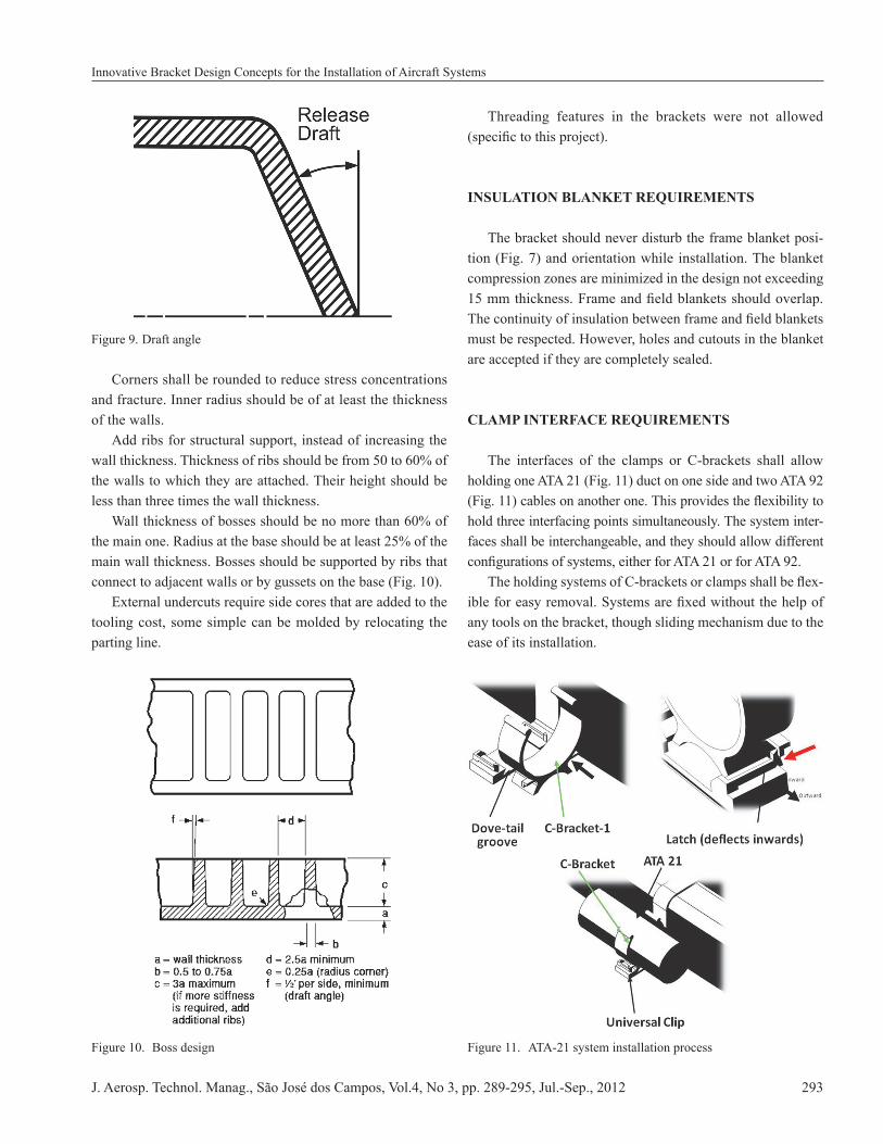
CLAMP INTERFACE REQUIREMENTS
The interfaces of the clamps or C-brackets shall allow
hold three interfacing points simultaneously. The system inter-faces shall be interchangeable, and they should allow different
-
any tools on the bracket, though sliding mechanism due to the ease of its installation.
Innovative Bracket Design Concepts for the Installation of Aircraft Systems
Figure 11. ATA-21 system installation process
J. Aerosp. Technol. Manag., São José dos Campos, Vol.4, No 3, pp. 289-295, Jul.-Sep., 2012 293
The bracket should not exert excessive pressure on the ECS* ducts. These are nonstructural, pre-peg, carbon fiber composite ducts used for air circulation in the flight deck. ECS ducts help in maintaining the cabin air quality in commercial aircrafts, enabling survival, safety, and comfort of passengers. The ECS ducts are installed within pressurized and unpressurized sections of fuselage and wing. The required clearances with the adjacent structures must be maintained for proper installation and removal for maintainability.
MATERIAL SELECTION FOR BRACKETS
Brackets are produced by the injection molding process. Hence, ABS or polyamides are the preferred materials. Injection molding is the most commonly used manufacturing
A wide variety of brackets is manufactured, which varies greatly in their size, complexity, and application.
BEST PRACTICES
without crushing the wires and yet tight enough to prevent movement within the clamp. Wires and wire bundles are
avoiding the wire pinching. Clamps on wire bundles should not allow the bundle to move through the clamp against the pulling force when applied. Clamps must be installed with their attachment hardware positioned above them, wherever is practicable so that they are
Clamps must be installed in such a manner that the electri-cal wires do not come in contact with other parts of the aircraft when subjected to vibration.
DESIGN SOLUTION PROCESS
Having in mind all of the design requirements and recommendations, the following design charter is framed in the development of innovative brackets design. Several concepts were developed with a criteria list consist-ing of design key drivers, i.e., systems integration, structure impact, assembly, maintenance, and manufacturability. The
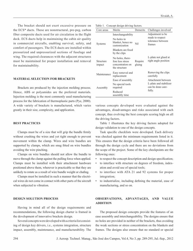
various concepts developed were evaluated against the advantages, disadvantages and risks associated with each concept, thus evolving the best concepts scoring high on all the driving factors. Table 1 illustrates the key driving factors adopted for design validation to one of the design concepts.
was checked against the minimum requirements listed in it. This ensures that the design criteria have been followed all through the design cycle and there are no deviations from the scope of the project. Some of the key checkpoints are the
-ation and avoid use of special tools;
integration;
manufacturing, and so on.
OBSERVATIONS, ADVANTAGES, AND VALUE ADDITION
The proposed design concepts provide the features of an ease assembly and interchangeability. The designs ensure that no holes are provided in neither of the brackets, thus avoiding the weak sections or stress concentration on the blankets and frames. The designs also ensure that no standard or special
Sivaiah, A.
Table 1. Concept design driving factors.Core areas Merits Demerits Challenges involved
Systems
Interchangeability
Nil
Adjustment to be made to respect tolerance between frames
No holes in blanket, hence no customization
by the clips
Structure impact
No holes, there-fore less stress concentration on the structure
Require gluing
L-plate not glued at right angle position
Maintenance Easy removal and replacement
Removing the clips carefully
Assembly
Ease of assembly Attachment between L-plate and stabilizer can be done care-fully.
No special tools required Reduced assembly time
J. Aerosp. Technol. Manag., São José dos Campos, Vol.4, No 3, pp. 289-295, Jul.-Sep., 2012294
assembly tools are required for the bracket installation, which save a lot of assembly time. It is easy to replace the spares by the maintenance staff during the periodic maintenance. It is also very moderate on manufacturing aspects of the new concepts. The weight to cost ratio, which is an implied design criterion, was also taken care in the basic design.
CONCLUSIONS
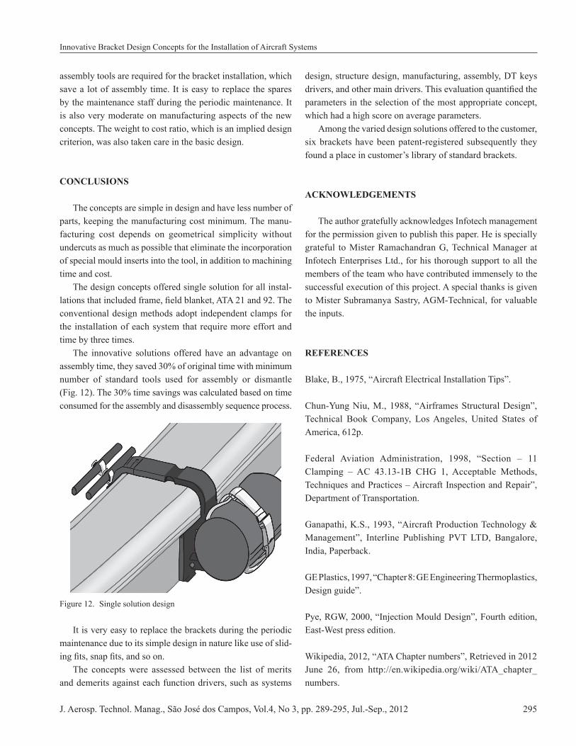
The concepts are simple in design and have less number of parts, keeping the manufacturing cost minimum. The manu-facturing cost depends on geometrical simplicity without undercuts as much as possible that eliminate the incorporation of special mould inserts into the tool, in addition to machining time and cost. The design concepts offered single solution for all instal-
conventional design methods adopt independent clamps for the installation of each system that require more effort and time by three times. The innovative solutions offered have an advantage on
number of standard tools used for assembly or dismantle
consumed for the assembly and disassembly sequence process.
Figure 12. Single solution design
It is very easy to replace the brackets during the periodic maintenance due to its simple design in nature like use of slid-
The concepts were assessed between the list of merits and demerits against each function drivers, such as systems
design, structure design, manufacturing, assembly, DT keys
parameters in the selection of the most appropriate concept, which had a high score on average parameters. Among the varied design solutions offered to the customer, six brackets have been patent-registered subsequently they found a place in customer�’s library of standard brackets.
ACKNOWLEDGEMENTS
The author gratefully acknowledges Infotech management for the permission given to publish this paper. He is specially grateful to Mister Ramachandran G, Technical Manager at Infotech Enterprises Ltd., for his thorough support to all the members of the team who have contributed immensely to the successful execution of this project. A special thanks is given to Mister Subramanya Sastry, AGM-Technical, for valuable the inputs.
REFERENCES
Technical Book Company, Los Angeles, United States of
Department of Transportation.
India, Paperback.
East-West press edition.
numbers.
Innovative Bracket Design Concepts for the Installation of Aircraft Systems
J. Aerosp. Technol. Manag., São José dos Campos, Vol.4, No 3, pp. 289-295, Jul.-Sep., 2012 295