Embed Size (px)
Citation preview

Innovative Approach Integrated BuildingInnovative ofApproach of Integrated Building Enclosure and HVAC Systems Modeling to ImproveEnclosure and HVAC Systems Modeling to Improve Building Energy Efficient DesignBuilding Energy Efficient Design
Pongsak Chaisuparasmikul, PhD, architect, DOE2.1E Consultant
Center for Sustainable Cities, School of Architecture, University of Kentucky,
Lexington, KY, 40506-0041 U.S.A.

Pongsak Chaisuparasmikul Building Enclosure Science and TechnoloPongsak Chaisuparasmikul Building Enclosure Science and Technology Conference June 12,2008gy Conference June 12,2008
Concept andConcept and ProcessProcess
Define data modeling, information exchange andsimulation Engine
Integrate and differential between building envelopeand HVACR
Reduce energy consumption through standardisation,which is recognised as a key element in design time,cutting construction costs and ensuring efficient building solutions
Demonstrate indoor environmental quality (ventilation,lighting, thermal gain/loss).
Interoperability Meet criteria Codes Compliance is the minimum
standard to Evaluate options for a net zero energy building
Pongsak Chaisuparasmikul Building Enclosure Science and TechnoloPongsak Chaisuparasmikul Building Enclosure Science and Technology Conference June 12,2008gy Conference June 12,2008
Model DefinitionModel Definition
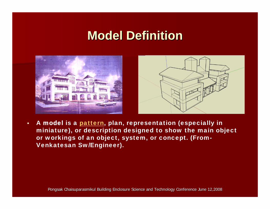
A model is a pattern, plan, representation (especially in miniature), or description designed to show the main object or workings of an object, system, or concept. (From-Venkatesan Sw/Engineer).
Pongsak Chaisuparasmikul Building Enclosure Science and TechnoloPongsak Chaisuparasmikul Building Enclosure Science and Technology Conference June 12,2008gy Conference June 12,2008
BuildingBuilding Information LibraryInformation Library
Looking for doors? Roofing materials? Need specificationsfor below-grade vapor retarders? detailed building productinformation you need.
Building Information Library includes a library of buildingproduct information designed for the needs of the AEC community -- allowing to seamlessly insert specs, technicaldata sheets, CAD documents and Smart-BIM objects into the drawings and building models, search and find formattedbuilding product information which includes;
Company profilesCompany profiles 33--Part specificationsPart specifications Technical data sheetsTechnical data sheets Manufacturer's catalogsManufacturer's catalogs CAD documentsCAD documents SmartBIMSmartBIM objectsobjects

Pongsak Chaisuparasmikul Building Enclosure Science and TechnoloPongsak Chaisuparasmikul Building Enclosure Science and Technology Conference June 12,2008gy Conference June 12,2008
Data Exchange ModelData Exchange Model
The complexity of a building enclosure can be represented as an object oriented, where the building model parameters, and design variables are defined as classes, subclasses, and events.
Data in building’s objects (Both graphics and Attributes) are stored as the instance of class (integer, double, float, string, Boolean or they can refer to objects in other class) which defines type of the object, as well as the kind of the operations that it performs.
BUILDING MODEL
VMS
VME
BUILDING DATA MODELDATABASE-
MAPPING
USER INTERFACE
REPORT GRAPHS AND CHARTS
DATA OUTDATA IN
ENERGY OUTPUT POST PROCESSING
DATABASE-MAPPING
WHAT IF SCENARIOS
INFORM DESIGN DECISION
THERMAL DAYLIGHT AIRFLOW
ENERGY INPUT PRE
PROCESSING
GEOMETRICAL MODEL
SITE-CLIMATE LOCATION
SIMULATION ENGINE
THERMAL ZONE
THERMAL SURFACE
SPACE AND ZONE
MATERIALS AND CONSTRUCTION
ENERGY INPUT PARAMETERS
VME APPLICATION PROGRAM INTERFACE
Pongsak Chaisuparasmikul Building Enclosure Science and TechnoloPongsak Chaisuparasmikul Building Enclosure Science and Technology Conference June 12,2008gy Conference June 12,2008
Data Exchange ModelData Exchange Model
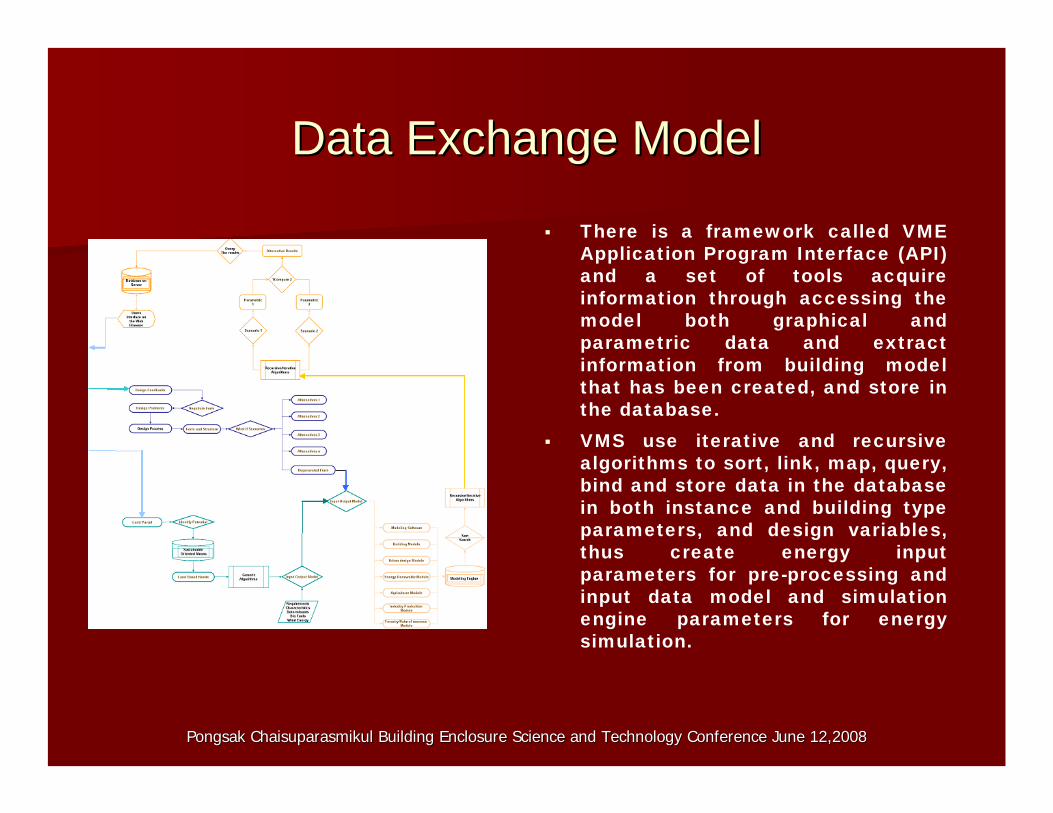
There is a framework called VME Application Program Interface (API) and a set of tools acquire information through accessing the model both graphical and parametric data and extract information from building model that has been created, and store in the database.
VMS use iterative and recursive algorithms to sort, link, map, query, bind and store data in the database in both instance and building type parameters, and design variables, thus create energy input parameters for pre-processing and input data model and simulation engine parameters for energy simulation.
Data Exchange ModelData Exchange Model
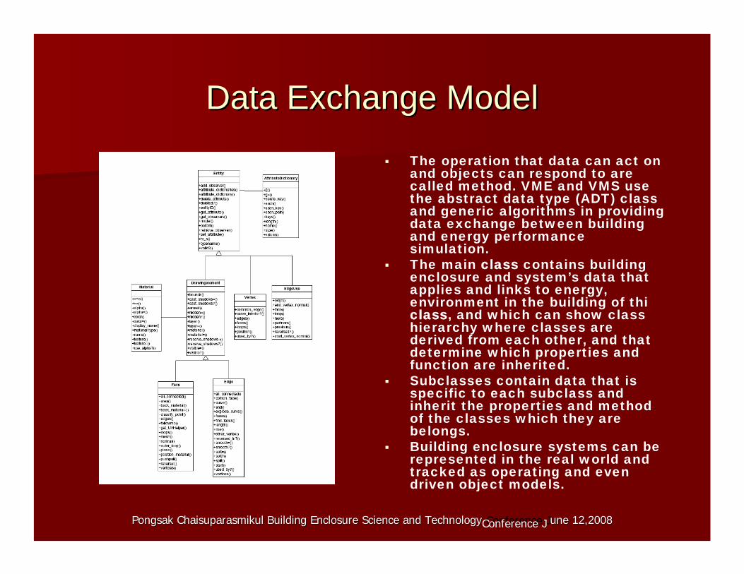
The operation that data can act onand objects can respond to arecalled method. VME and VMS use the abstract data type (ADT) classand generic algorithms in providingdata exchange between buildingand energy performance simulation.
The main class contains buildingenclosure and system’s data that applies and links to energy,environment in the building of thiclass, and which can show class hierarchy where classes arederived from each other, and thatdetermine which properties andfunction are inherited.
Subclasses contain data that is specific to each subclass and inherit the properties and method of the classes which they arebelongs.
Building enclosure systems can berepresented in the real world and tracked as operating and evendriven object models.
Pongsak Chaisuparasmikul Building Enclosure Science and TechnoloPongsak Chaisuparasmikul Building Enclosure Science and Technology Conference Jgy une 12,20une 12, 080Conference J 20 8
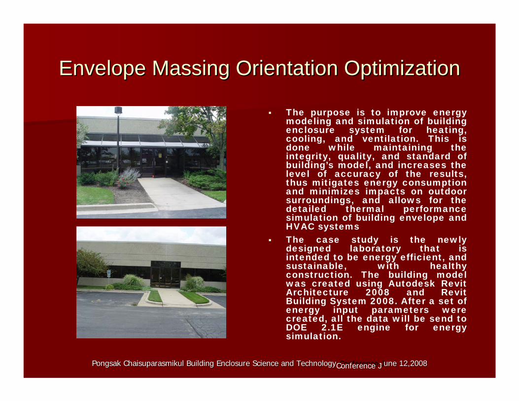
The purpose is to improve energymodeling and simulation of buildingenclosure system for heating,cooling, and ventilation. This is done while maintaining the integrity, quality, and standard of building’s model, and increases the level of accuracy of the results,thus mitigates energy consumptionand minimizes impacts on outdoor surroundings, and allows for thedetailed thermal performancesimulation of building envelope andHVAC systems
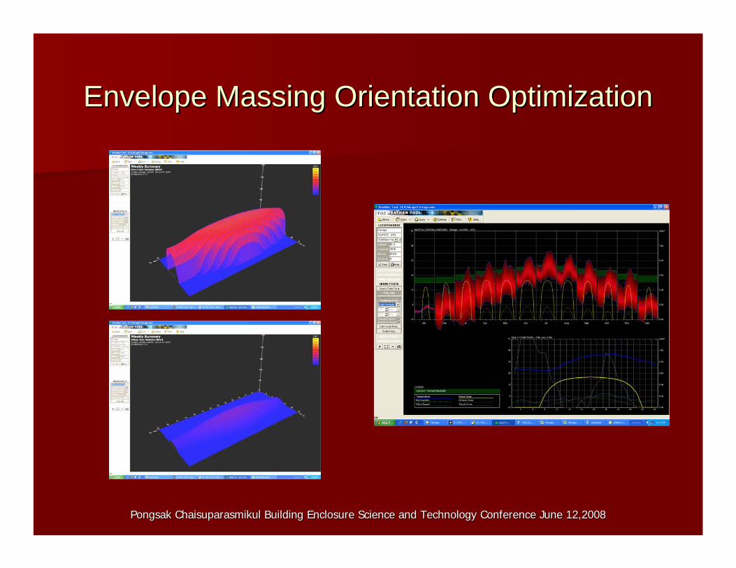
Envelope Massing Orientation OptimizationEnvelope Massing Orientation Optimization
The case study is the newlydesigned laboratory that is intended to be energy efficient, andsustainable, with healthyconstruction. The building model was created using Autodesk RevitArchitecture 2008 and Revit Building System 2008. After a set of energy input parameters were created, all the data will be send to DOE 2.1E engine for energysimulation.
Pongsak Chaisuparasmikul Building Enclosure Science and TechnoloPongsak Chaisuparasmikul Building Enclosure Science and Technology Conference Jgy une 12,20une 12, 080Conference J 20 8
Pongsak Chaisuparasmikul Building Enclosure Science and TechnoloPongsak Chaisuparasmikul Building Enclosure Science and Technology Conference June 12,2008gy Conference June 12,2008
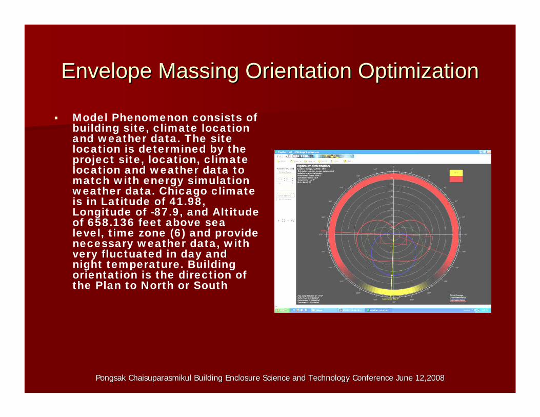
Envelope Massing Orientation OptimizationEnvelope Massing Orientation Optimization
Model Phenomenon consists of building site, climate locationand weather data. The site location is determined by the project site, location, climatelocation and weather data to match with energy simulationweather data. Chicago climateis in Latitude of 41.98,Longitude of -87.9, and Altitude of 658.136 feet above sea level, time zone (6) and provide necessary weather data, withvery fluctuated in day andnight temperature. Buildingorientation is the direction of the Plan to North or South
Pongsak Chaisuparasmikul Building Enclosure Science and TechnoloPongsak Chaisuparasmikul Building Enclosure Science and Technology Conference June 12,2008gy Conference June 12,2008
Envelope Massing Orientation OptimizationEnvelope Massing Orientation Optimization
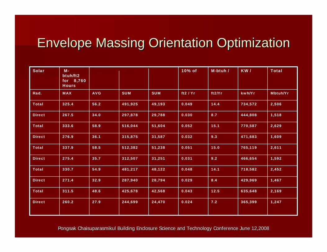
1,247365,3997.20.02424,470244,69927.9260.2Direct
2,169635,64812.50.04342,568425,67848.6311.5Total
1,467429,9698.40.02928,794287,94032.9271.4Direct
2,452718,58214.10.04848,122481,21754.9330.7Total
1,592466,6549.20.03131,251312,50735.7275.4Direct
2,611765,11915.00.05151,238512,38258.5337.9Total
1,609471,6839.30.03231,587315,87536.1276.9Direct
2,629770,58715.10.05251,604516,04458.9333.6Total
1,518444,8088.70.03029,788297,87834.0267.5Direct
2,506734,57214.40.04949,193491,92556.2325.4Total
Mbtuh/Yrkwh/Yrft2/Yrft2 / YrSUMSUMAVGMAXRad.
TotalKW /M-btuh /10% ofMbtuh/ft2 for 8,760 Hours
Solar
Envelope Massing Orientation OptimizationEnvelope Massing Orientation OptimizationW
et B
ulb
Tem
p (C
) D
ry B
ulb
Tem
p (C
)
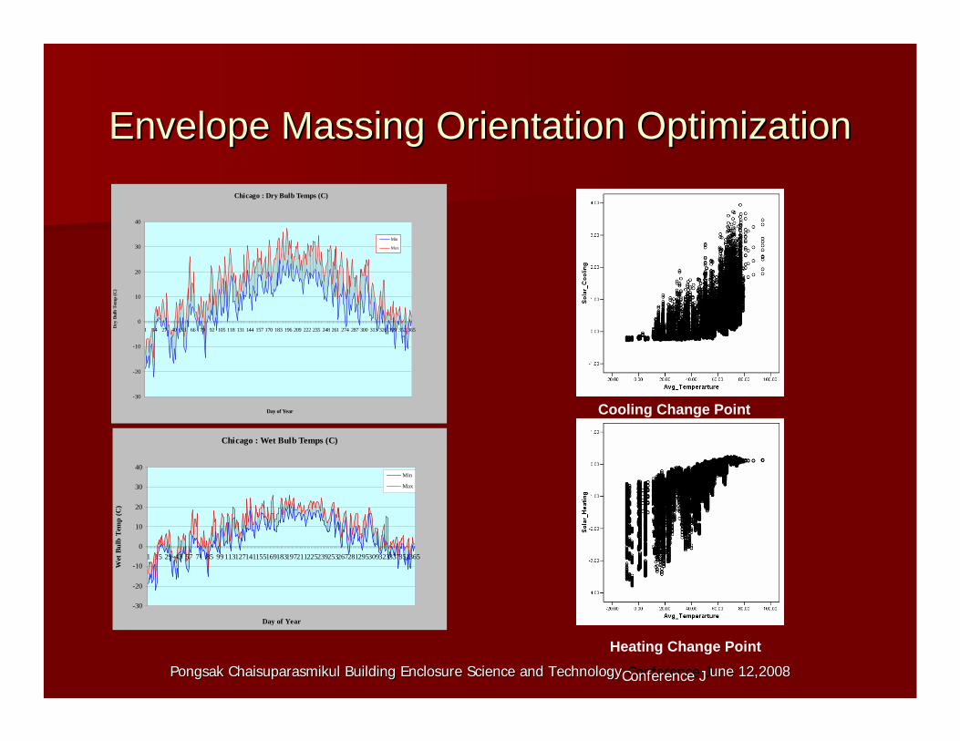
Chicago : Dry Bulb Temps (C)
40
Min
30 Max
20
10
0 1 14 27 40 53 66 79 92 105 118 131 144 157 170 183 196 209 222 235 248 261 274 287 300 313326339 352365
-10
-20
-30
Day of Year Cooling Change Point
Chicago : Wet Bulb Temps (C)
40Min
Max30
20
10
0
1 15 29 43 57 71 85 99 113127141155169183197211225239253267281295309323337351365-10
-20
-30
Day of Year
Heating Change Point
Pongsak Chaisuparasmikul Building Enclosure Science and TechnoloPongsak Chaisuparasmikul Building Enclosure Science and Technology Conference Jgy une 12,20une 12, 080Conference J 20 8
Pongsak Chaisuparasmikul Building Enclosure Science and TechnoloPongsak Chaisuparasmikul Building Enclosure Science and Technology Conference June 12,2008gy Conference June 12,2008
Envelope Massing Orientation OptimizationEnvelope Massing Orientation Optimization
Pongsak Chaisuparasmikul Building Enclosure Science and TechnoloPongsak Chaisuparasmikul Building Enclosure Science and Technology Conference June 12,2008gy Conference June 12,2008
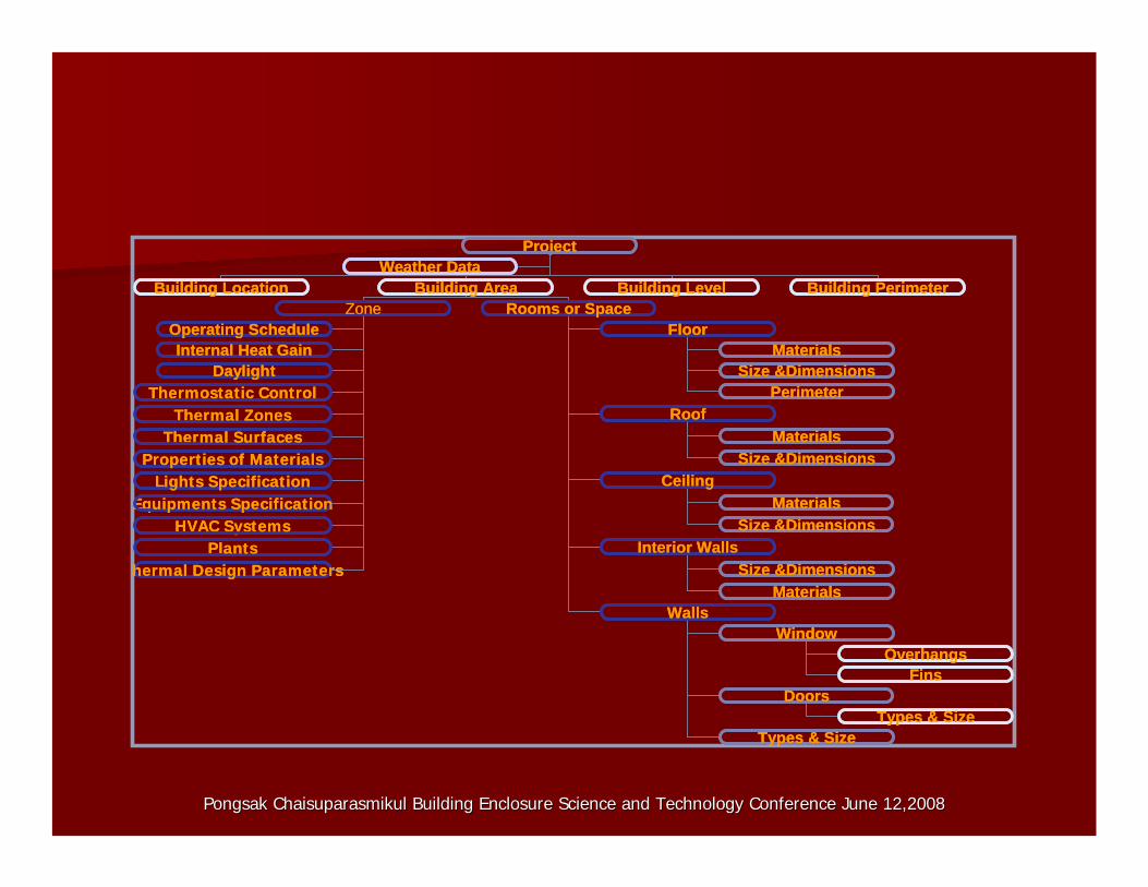
Project
Building Location Building Area Building Level Building Perimeter Weather Data
Zone Operating Schedule
Rooms or Space
Internal Heat Gain Daylight
Floor
Roof
Ceiling
Interior Walls
Walls Window
Doors
Overhangs
Materials
Materials
Materials Size &Dimensions
Size &Dimensions
Size &Dimensions
Fins
Size &Dimensions Materials
Types & Size Types & Size
Perimeteratic Control nes
rfaces s of Materials
ion ents Specification
rmal Design Parameters
Proj
ThermostTherThermal ZoTher
Thermal SuTherPropertiePr
Lights SpecificatLEquipmEq
HVAC SystemsHVAC SystPlantsPl
TheT
ect
Building Location Building Area Building Level Building PerimeterWeather Data
ZoneOperating Schedule
Rooms or Space
Internal Heat GainDaylight
Floor
Roof
Ceiling
Interior Walls
WallsWindow
Doors
Overhangs
Materials
Materials
MaterialsSize &Dimensions
Size &Dimensions
Size &Dimensions
Fins
Size &DimensionsMaterials
Types & SizeTypes & Size
Perimetermostatic Controlmal Zones
mal Surfacesoperties of Materialsights Specification
uipments Specificationems
antshermal Design Parameters
Pongsak Chaisuparasmikul Bu oloPongsak Chaisuparasmikul B
to F ll In:to
ilding Enclosure Science and Technuilding Enclosure Science and Technology Conference June 12,2008gy Conference June 12,2008
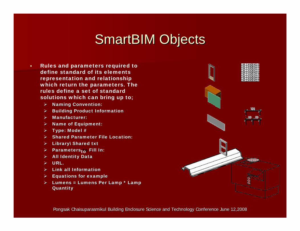
SmartBIMSmartBIM ObjectsObjects
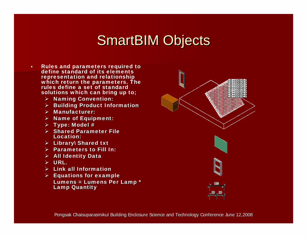
Rules and parameters required to define standard of its elements representation and relationship which return the parameters. The rules define a set of standard solutions which can bring up to;
Naming Convention:Naming Convention:Building Product InformationBuilding Product InformationManufacturer:Manufacturer: Name of Equipment:Name of Equipment:Type: Model #Type: Model #Shared Parameter File Location:Shared Parameter File Location:LibraryLibrary\\ Shared txtShared txtParameters iParameters Fill In:All Identity DataAll Identity DataURL.URL.Link all InformationLink all InformationEquations for exampleEquations for example Lumens = Lumens Per Lamp *Lumens = Lumens Per Lamp * LampLampQuantityQuantity
tt tith ibPongsak Chaisuparasmikul Building Enclosure Science and TechnoloPongsak Chaisuparasmikul Building Enclosure Science and Technology Conference June 12,2008gy Conference June 12,2008
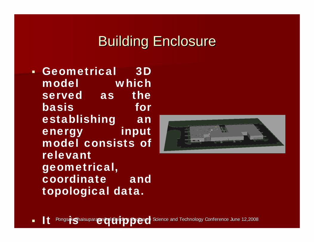
Building EnclosureBuilding Enclosure
Geometrical 3D model which served as the basis for establishing an energy inputmodel consists of relevant geometrical,coordinate and topological data.
It is equipped
Pongsak Chaisuparasmikul Building Enclosure Science and TechnoloPongsak Chaisuparasmikul Building Enclosure Science and Technology Conference June 12,2008gy Conference June 12,2008
Building EnclosureBuilding Enclosure
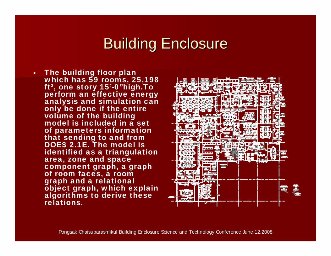
The building floor planwhich has 59 rooms, 25,198ft², one story 15’-0”high.Toperform an effective energyanalysis and simulation canonly be done if the entirevolume of the buildingmodel is included in a set of parameters informationthat sending to and fromDOE$ 2.1E. The model is identified as a triangulationarea, zone and spacecomponent graph, a graphof room faces, a roomgraph and a relationalobject graph, which explainalgorithms to derive theserelations.
Pongsak Chaisuparasmikul Building Enclosure Science and TechnoloPongsak Chaisuparasmikul Building Enclosure Science and Technology Conference June 12,2008gy Conference June 12,2008
Building EnclosureBuilding Enclosure
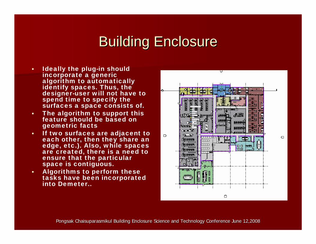
Ideally the plug-in shouldincorporate a generic algorithm to automaticallyidentify spaces. Thus, the designer-user will not have tospend time to specify the surfaces a space consists of.
The algorithm to support this feature should be based on geometric facts
If two surfaces are adjacent to each other, then they share an edge, etc.). Also, while spacesare created, there is a need toensure that the particular space is contiguous.
Algorithms to perform thesetasks have been incorporatedinto Demeter..

Pongsak Chaisuparasmikul Building Enclosure Science and TechnoloPongsak Chaisuparasmikul Building Enclosure Science and Technology Conference June 12,2008gy Conference June 12,2008
Building EnclosureBuilding Enclosure
Grand total: 11
25198Grand total: 11
866' - 5 1/32"3329KCorridor
216' - 9 7/16"70' 3"2906JGriffith Lab2
95' - 2 3/16"153' 11"104' 0"422IRegulatory
91' - 3 13/32"153' 11"70' 3"490HToilet
234' - 9"65' 8"99' 8"1689GConference
225' - 4 7/8"0' 0"0' 0"2385FKitchen Dining
212' - 8 3/16"45 5 "41 2"2207EWarehouse
301' - 0 13/16"
99' 10"129' 8"3183DOpen plan office
128' - 8 19/32"
175' 10"65' 6"829CReception
157' - 1 5/8"175' 10"0' 0"953BOffice
430' - 4 5/32"49' 10"0' 0"6805AGriffith Lab1
AzimuthYXft²
PerimeterZone OriginAreaBlockSpace Zone
Pongsak Chaisuparasmikul Building Enclosure Science and TechnoloPongsak Chaisuparasmikul Building Enclosure Science and Technology Conference June 12,2008gy Conference June 12,2008
Building EnclosureBuilding Enclosure
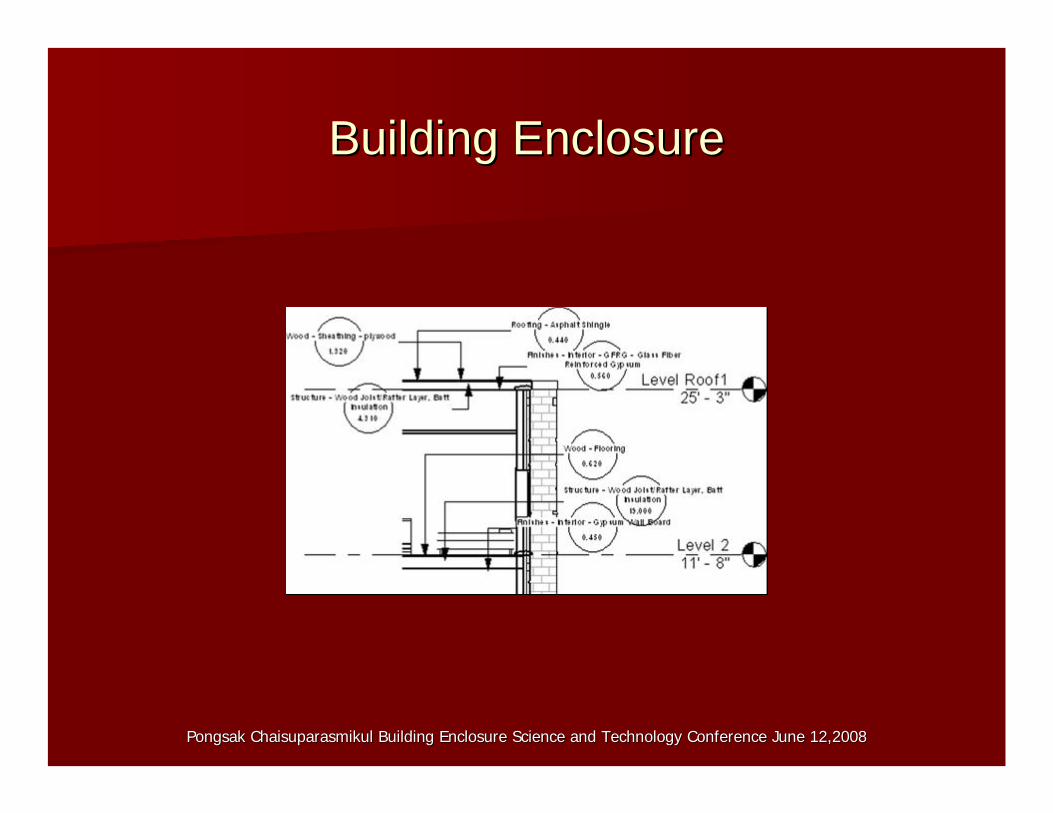
Rooms or Space Geometrical Model Building model was transferring and translated its
geometrical, topological and coordinates data into floor area,rooms or space volume model, decomposing into a so-calledconnection model and then extracting volume bodies intoelements and components. Air flow and thermal energymodel are derived from rooms or space geometric model, andshows knowledge of linkage between model hierarchieswhere the coupling strategies are implemented. Figure 4shows the technique is demonstrated within the scope ofbuilding energy simulation by dividing the space into zonesfor setting up a thermal multi-zone model and a geometricalmodel. The algorithm is basically applicable to any buildingenergy simulation software tool. Room parameters aredefinable spatial relationships, which can show therelationship between any elements, properties and space ina floor plan
Pongsak Chaisuparasmikul Building Enclosure Science and TechnoloPongsak Chaisuparasmikul Building Enclosure Science and Technology Conference June 12,2008gy Conference June 12,2008
Building EnclosureBuilding Enclosure
Surface and space attribution The model created in the sketching environment
consists of many surfaces which form spaces. Eachsurface has its own identity (ID) so that it can be referenced whenever necessary. Surface attribution isalso an essential part of building simulation modelling.By attributing surfaces the user can specify whetherthe specific surface is an external or an internal wall,underground or roof slab, etc. In terms of openingsattribution, the tool should be able to identify whethera sub-surface is attached to another so that the opening (sub-surface) can be referenced with regardsto the surface attached. Then the attribution of the openings could be established by specifying theopening type (fixed window, air, skylight. sliding door,etc.)
Pongsak Chaisuparasmikul Building Enclosure Science and TechnoloPongsak Chaisuparasmikul Building Enclosure Science and Technology Conference June 12,2008gy Conference June 12,2008
Building EnclosureBuilding Enclosure
HVAC Thermal Zone Model Thermal zone model in turn is a dimensionally reduced
model. It can be described by an geometricrepresentations of thermal zones, and for each thermalzone that enclosed heat transfer surfaces, whichrepresents the building structure in a hierarchical manner, i.e. the model is organized in building level,rooms, building components, layers, materials, etc Theprerequisites for establishing a numerical couplingbetween both approaches are incidence matrices relating models and components. In other words, aCFD and HVAC simulation requires volume bodies ofair volumes together with boundary conditions while athermal multi-zone simulation.
Pongsak Chaisuparasmikul Bu oloPongsak Chaisuparasmikul B ilding Enclosure Science and Technuilding Enclosure Science and Technology Conference June 12,2008gy Conference June 12,2008
Building EnclosureBuilding Enclosure
Thermal surfaces refer to heat transfer surfaces to describe the thermal representations of buildingsurfaces, such as walls, roof, windows, doors, ceiling,and floor. Each surface has some attributes to determine its interaction between internal and external environment. The surfaces in Table 3 allows to fill information regarding surfaces to represent interzone heat transfer. Thermal surfaces are the basic ingredients of the thermal simulation. A SIMULATION PROJECT AGGREGATES A NUMBER OF ZONES, WHERETHE LATTER AGGREGATE ONE OR MORE AIR VOLUMES. AIR volume objects are aware of thecorresponding set of adjacent bodies and theirsemantics. Structural elements themselves are composed of a multilayered structure with respectiveindividual materials. Although they form part of thegeometric model, we also tore the surface geometryand vertex coordinates.
Pongsak Chaisuparasmikul Building Enclosure Science and TechnoloPongsak Chaisuparasmikul Building Enclosure Science and Technology Conference June 12,2008gy Conference June 12,2008
Building EnclosureBuilding Enclosure
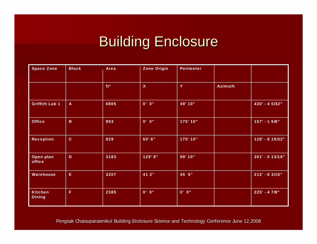
225' - 4 7/8"0' 0"0' 0"2385FKitchen Dining
212' - 8 3/16"45 5"41 2"2207EWarehouse
301' - 0 13/16"99' 10"129' 8"3183DOpen plan office
128' - 8 19/32"175' 10"65' 6"829CReception
157' - 1 5/8"175' 10"0' 0"953BOffice
430' - 4 5/32"49' 10"0' 0"6805AGriffith Lab 1
AzimuthYXft²
PerimeterZone OriginAreaBlockSpace Zone
Pongsak Chaisuparasmikul Building Enclosure Science and TechnoloPongsak Chaisuparasmikul Building Enclosure Science and Technology Conference June 12,2008gy Conference June 12,2008
Building EnclosureBuilding Enclosure

==
Pongsak Chaisuparasmikul Building Enclosure Science and TechnoloPongsak Chaisuparasmikul Building Enclosure Science and Technology Conference June 12,2008gy Conference June 12,2008
Building EnclosureBuilding Enclosure
Large Double-Glazed Windows (Reflective Coating) - Industry (U=0.5636)
Large Double-Glazed Windows (Reflective Coating) - Industry (U=0.5636)
Skylights
Large Single-Glazed Windows (U=0.6498)
Large Single-Glazed Windows (U=0.6498)
Interior Windows
Large Double-Glazed Windows (Reflective Coating) Glass (U=0.29, SC=0.31, SHCC=0.265, Vis=0.65,)
Large Double-Glazed Windows (Reflective Coating) Glass (U=0.46, Glass (U=0.46, SC=0.31, SHCC=0.265, Vis=0.65,)
Exterior Windows
Metal Door (U=0.6516)Metal Door (U=0.6516)Doors
8 In. Light Weight Concrete Floor Deck (U 0.2395)
8 In. Light Weight Concrete Floor Deck (U 0.2395)
Floors
4 In. Light Weight Concrete (U=0.2254)
4 In. Light Weight Concrete (U=0.2254)
Roofs
Un-Insulated Solid-Ground Floor (U=0.125)
Un-Insulated Solid-Ground Floor (U=0.125)
Slabs
Frame Partition With 0.75 In. Gypsum Board (U=0.2589)
Frame Partition With 0.75 In. Gypsum Board (U=0.2589)
Interior Walls
8 In. Light Weight Concrete Block (U=0.060)
8 In. Light Weight Concrete Block (U=0.084)
Exterior Walls
1 = Proposed0 = Baseline STD90.1Parameter
Exterior Envelope

Pongsak Chaisuparasmikul Bu oloPongsak Chaisuparasmikul B ilding Enclosure Science and Technuilding Enclosure Science and Technology Conference June 12,2008gy Conference June 12,2008
HVACRHVACR
Specify Space and Zone Parameters for Energy Analysis andSimulation
Room instance parameters that were used for energy analysis andsimulation and calculating heating and cooling loads are
Condition type or the type of conditioning for the room which consisting of the followings;
HeatedHeatedCooledCooledHeated and cooledHeated and cooled UnconditionedUnconditioned VentedVented Naturally vented onlyNaturally vented only
Airflow consists of supply, return, and exhaust airflow. Supply airflow is the sum of the supply airflow for all the suppSupply airflow is the sum of the supply airflow for all the supply airly airterminals in the room.terminals in the room.Return airflow is the return ai rflow for all the return air terReturn airflow is the return ai rflow for all the return air terminals in theminals in the room.room.Exhaust airflow is the sum of the exhaust airflow for all the exExhaust airflow is the sum of the exhaust airflow for all the exhaust airhaust air terminals in the room.terminals in the room.
Pongsak Chaisuparasmikul Bu oloPongsak Chaisuparasmikul B ilding Enclosure Science and Technuilding Enclosure Science and Technology Conference June 12,2008gy Conference June 12,2008
HVACRHVACR
People Loads is the people in the room occupying aspace, which consist of
Number of People to specify a value based on the numberNumber of People to specify a value based on the numberof people assumed to occupy the room for loadof people assumed to occupy the room for loadcalculations.calculations. Area per Person to specify a value based on the areaArea per Person to specify a value based on the areaallotted per person.allotted per person. Sensible Heat Gain per PersonSensible Heat Gain per Person -- the portion of the heatthe portion of the heatgain directly given off by people occupying the space.gain directly given off by people occupying the space. Latent Heat Gain per PersonLatent Heat Gain per Person -- the load is associated withthe load is associated with the water vapors given off by people occupying the space.the water vapors given off by people occupying the space.
Lighting load is the sum of the lighting load for all thelighting fixtures within the space. The value can beexpressed as Watts or Watts per area or LightingPower Per Area
Pongsak Chaisuparasmikul Bu oloPongsak Chaisuparasmikul B ilding Enclosure Science and Technuilding Enclosure Science and Technology Conference June 12,2008gy Conference June 12,2008
HVACRHVACR
Reusability of components as a library that can becalled from multiple areas of the applications andapplication interface allowed the model to interactwith the simulation data and match with the simulation parameters in DOE2, and predicts thehourly energy use and energy cost of a building givenhourly weather information and a description of thebuilding, and its HVAC equipment and utility ratestructure. DOE2 will calculate the heating and coolingloads necessary to maintain thermal control setpoints, conditions throughout a secondary HVACsystem and coil loads, and the energy consumption ofprimary plant equipment to verify that the simulation isperforming as the actual building would. Designers candetermine the choice of building parameters thatimprove energy efficiency while maintaining thermalcomfort and cost-effectiveness. x
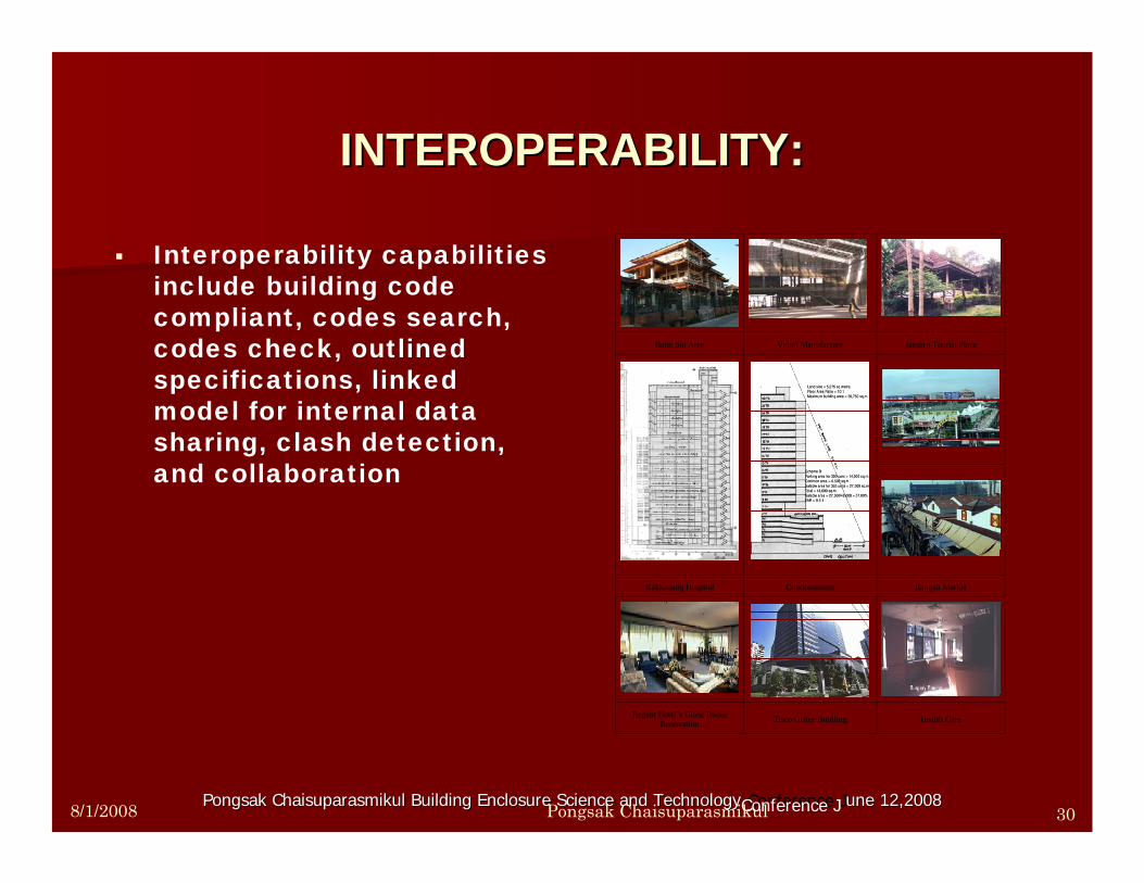
Interoperability capabilities include building code compliant, codes search, codes check, outlined specifications, linked model for internal data sharing, clash detection, and collaboration
Bann Soi Aree Veloil Manufacture Jaesorn Tourist Place
Kakkanang Hospital Condominium Rangsit Market
Regent Hotel’s Guest Room Renovation Tisco Office Buidling Health Care
INTEROPERABILITY:INTEROPERABILITY:
Pongsak Chaisuparasmikul Building Enclosure Science and TechnoloPongsak Chaisuparasmikul Building Enclosure Science and Technology Conference Jgy une 12,20une 12, 080Conference J 20 88/1/2008 Pongsak Chaisuparasmikul 30

Pongsak Chaisuparasmikul Bu oloPongsak Chaisuparasmikul B ilding Enclosure Science and Technuilding Enclosure Science and Technology Conference June 12,2008gy Conference June 12,2008
Prescriptive Envelope Energy CodePrescriptive Envelope Energy Code Compliance DataCompliance Data
Conference6.701689GConference
Kitchen Dining
9.462385FKitchen Dining
Warehouse8.752207EWarehouse
Open plan office
12.643183DOpen plan office
Reception3.29829CReception
Office3.78953BOffice
Griffith Lab 1
27.000.0846805AGriffith Lab 1
Space Zone
% Area of Activity
Dor+GlssDoor-AreaGlass-AreaWall-UTotal Surface
Area (ft²)
BlockSpace Zone
Pongsak Chaisuparasmikul Building Enclosure Science and TechnoloPongsak Chaisuparasmikul Building Enclosure Science and Technology Conference June 12,2008gy Conference June 12,2008
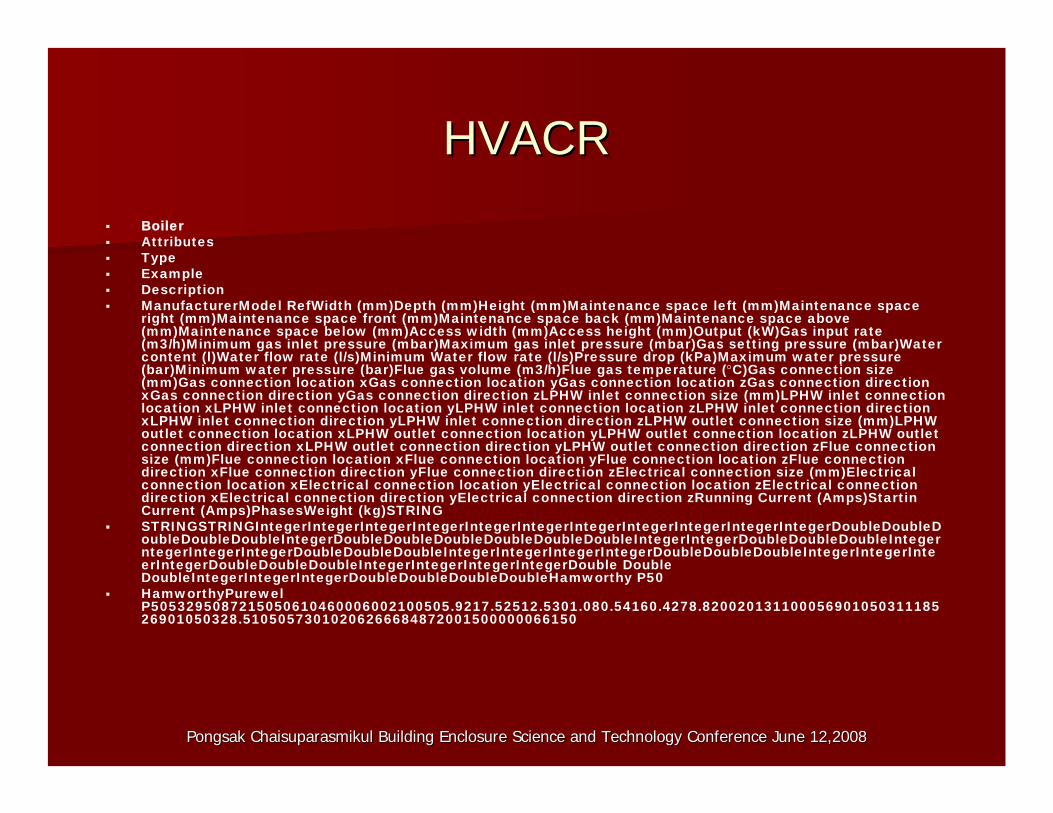
HVACRHVACR Boiler Attributes Type Example Description ManufacturerModel RefWidth (mm)Depth (mm)Height (mm)Maintenance space left (mm)Maintenance space
right (mm)Maintenance space front (mm)Maintenance space back (mm)Maintenance space above (mm)Maintenance space below (mm)Access width (mm)Access height (mm)Output (kW)Gas input rate(m3/h)Minimum gas inlet pressure (mbar)Maximum gas inlet pressure (mbar)Gas setting pressure (mbar)Watercontent (l)Water flow rate (l/s)Minimum Water flow rate (l/s)Pressure drop (kPa)Maximum water pressure (bar)Minimum water pressure (bar)Flue gas volume (m3/h)Flue gas temperature (°C)Gas connection size(mm)Gas connection location xGas connection location yGas connection location zGas connection direction xGas connection direction yGas connection direction zLPHW inlet connection size (mm)LPHW inlet connectionlocation xLPHW inlet connection location yLPHW inlet connection location zLPHW inlet connection direction xLPHW inlet connection direction yLPHW inlet connection direction zLPHW outlet connection size (mm)LPHWoutlet connection location xLPHW outlet connection location yLPHW outlet connection location zLPHW outlet connection direction xLPHW outlet connection direction yLPHW outlet connection direction zFlue connectionsize (mm)Flue connection location xFlue connection location yFlue connection location zFlue connectiondirection xFlue connection direction yFlue connection direction zElectrical connection size (mm)Electricalconnection location xElectrical connection location yElectrical connection location zElectrical connectiondirection xElectrical connection direction yElectrical connection direction zRunning Current (Amps)StartinCurrent (Amps)PhasesWeight (kg)STRING
STRINGSTRINGIntegerIntegerIntegerIntegerIntegerIntegerIntegerIntegerIntegerIntegerIntegerDoubleDoubleDoubleDoubleDoubleIntegerDoubleDoubleDoubleDoubleDoubleDoubleIntegerIntegerDoubleDoubleDoubleIntegerntegerIntegerIntegerDoubleDoubleDoubleIntegerIntegerIntegerIntegerDoubleDoubleDoubleIntegerIntegerInteerIntegerDoubleDoubleDoubleIntegerIntegerIntegerIntegerDouble Double DoubleIntegerIntegerIntegerDoubleDoubleDoubleDoubleHamworthy P50
HamworthyPurewelP5053295087215050610460006002100505.9217.52512.5301.080.54160.4278.820020131100056901050311185 26901050328.51050573010206266684872001500000066150

Pongsak Chaisuparasmikul Building Enclosure Science and TechnoloPongsak Chaisuparasmikul Building Enclosure Science and Technology Conference June 12,2008gy Conference June 12,2008
Pump AttributesType ExampleDescription ManufacturerModel RefWidth (mm)Depth (mm)Height (mm)Maintenance space
left (mm)Maintenance space right (mm)Maintenance space front(mm)Maintenance space back (mm)Maintenance space above(mm)Maintenance space below (mm)Access width (mm)Access height(mm)Power (kW)Water Flow Rate (l/s)Pressure Drop (kPa)LPHW inlet connection size (mm)LPHW inlet connection location xLPHW inlet connection location yLPHW inlet connection location zLPHW inlet connection direction xLPHW inlet connection direction yLPHW inlet connection direction zLPHWoutlet connection size (mm)LPHW outlet connection location xLPHW outlet connection location yLPHW outlet connection location zLPHW outlet connection direction xLPHW outlet connection direction yLPHW outlet connection direction zElectrical connection size (mm)Electrical connection location xElectrical connection location yElectrical connection location zElectrical connection direction xElectrical connection direction yElectricaconnection direction zRunning Current (Amps)Starting Current (Amps)PhasesWeight (kg)STRING
STRINGSTRINGIntegerIntegerIntegerIntegerIntegerIntegerIntegerIntegerInteerIntegerIntegerDoubleDoubleDoubleIntegerDoubleDoubleDoubleIntegerIntegrIntegerIntegerDoubleDoubleDoubleIntegerIntegerIntegerIntegerDouble Double DoubleIntegerIntegerIntegerDoubleDoubleDoubleDoublePullen beltdrivenPullenSerie C50L2c55065010000060060000600210050100605027550150000150502101500001 50000009090320

Pongsak Chaisuparasmikul Building Enclosure Science and TechnoloPongsak Chaisuparasmikul Building Enclosure Science and Technology Conference June 12,2008gy Conference June 12,2008
Pressurisation unit AttributesType ExampleDescription ManufacturerModel RefWidth (mm)Depth (mm)Height (mm)Maintenance space
left (mm)Maintenance space right (mm)Maintenance space front(mm)Maintenance space back (mm)Maintenance space above(mm)Maintenance space below (mm)Access width (mm)Access height(mm)System Volume (l)System Temperature (°C)Vessel Volume (l)Fill Pressure (bar)Static head (bar)Antifreeze percentage (%)Maximum Temperature(°C)Mains supply connection size (mm)Mains supply location xMains suppllocation yMains supply location zMains supply direction xMains supplydirection yMains supply direction zSystem fill connection size (mm)System fill connection location xSystem fill connection location ySystem fill connection location zSystem fill connection direction x System fill connection direction ySystem fill connection direction zElectrical connection size (mm)Electricalconnection location xElectrical connection location yElectrical connection location zElectrical connection direction xElectrical connection direction yElectrical connection direction zMotor Size (kW)Running Current (Amps)Starting Current (Amps)PhasesWeight (kg)STRING
STRINGSTRINGIntegerIntegerIntegerIntegerIntegerIntegerIntegerIntegerInteerIntegerIntegerDoubleIntegerDoubleDoubleDoubleIntegerIntegerIntegerDoubleDoubleDoubleIntegerIntegerIntegerIntegerDoubleDoubleDoubleIntegerIntegrIntegerIntegerDouble Double DoubleIntegerIntegerIntegerDoubleDoubleDoubleDoubleDoublePressurisationUnitPullenPulpress 2000 FD50725615174060006003000060021008082505.51.52010015-100400155001015-2550016500-1050000010.373.23.21105
Pongsak Chaisuparasmikul Building Enclosure Science and TechnoloPongsak Chaisuparasmikul Building Enclosure Science and Technology Conference June 12,2008gy Conference June 12,2008
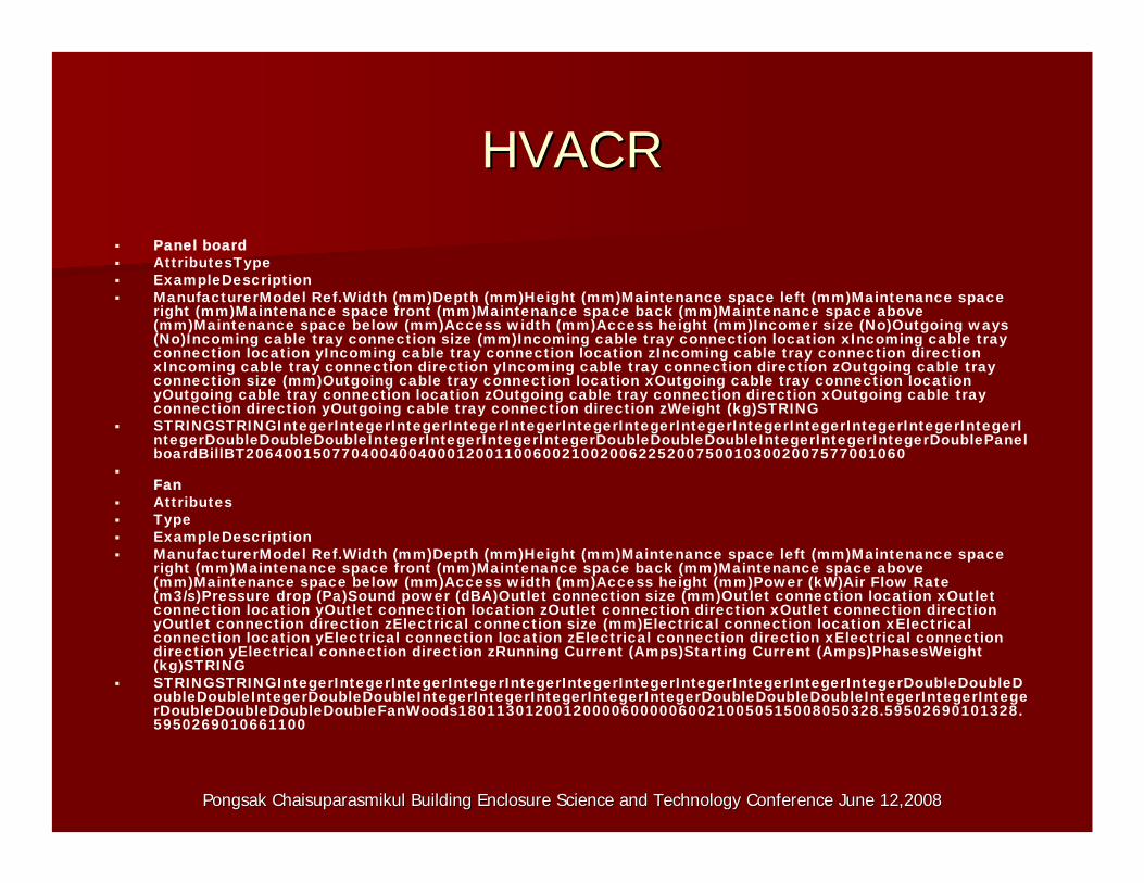
HVACRHVACR Panel board AttributesType ExampleDescription ManufacturerModel Ref.Width (mm)Depth (mm)Height (mm)Maintenance space left (mm)Maintenance space
right (mm)Maintenance space front (mm)Maintenance space back (mm)Maintenance space above (mm)Maintenance space below (mm)Access width (mm)Access height (mm)Incomer size (No)Outgoing ways(No)Incoming cable tray connection size (mm)Incoming cable tray connection location xIncoming cable trayconnection location yIncoming cable tray connection location zIncoming cable tray connection direction xIncoming cable tray connection direction yIncoming cable tray connection direction zOutgoing cable tray connection size (mm)Outgoing cable tray connection location xOutgoing cable tray connection location yOutgoing cable tray connection location zOutgoing cable tray connection direction xOutgoing cable tray connection direction yOutgoing cable tray connection direction zWeight (kg)STRING
STRINGSTRINGIntegerIntegerIntegerIntegerIntegerIntegerIntegerIntegerIntegerIntegerIntegerIntegerIntegerIntegerDoubleDoubleDoubleIntegerIntegerIntegerIntegerDoubleDoubleDoubleIntegerIntegerIntegerDoublePanelboardBillBT206400150770400400400012001100600210020062252007500103002007577001060
Fan
Attributes Type ExampleDescription ManufacturerModel Ref.Width (mm)Depth (mm)Height (mm)Maintenance space left (mm)Maintenance space
right (mm)Maintenance space front (mm)Maintenance space back (mm)Maintenance space above (mm)Maintenance space below (mm)Access width (mm)Access height (mm)Power (kW)Air Flow Rate(m3/s)Pressure drop (Pa)Sound power (dBA)Outlet connection size (mm)Outlet connection location xOutletconnection location yOutlet connection location zOutlet connection direction xOutlet connection direction yOutlet connection direction zElectrical connection size (mm)Electrical connection location xElectricalconnection location yElectrical connection location zElectrical connection direction xElectrical connection direction yElectrical connection direction zRunning Current (Amps)Starting Current (Amps)PhasesWeight(kg)STRING
STRINGSTRINGIntegerIntegerIntegerIntegerIntegerIntegerIntegerIntegerIntegerIntegerIntegerDoubleDoubleDoubleDoubleIntegerDoubleDoubleIntegerIntegerIntegerIntegerIntegerDoubleDoubleDoubleIntegerIntegerIntegerDoubleDoubleDoubleDoubleFanWoods18011301200120000600000600210050515008050328.59502690101328. 5950269010661100
- -
Pongsak Chaisuparasmikul Building Enclosure Science and TechnoloPongsak Chaisuparasmikul Building Enclosure Science and Technology Conference June 12,2008gy Conference June 12,2008
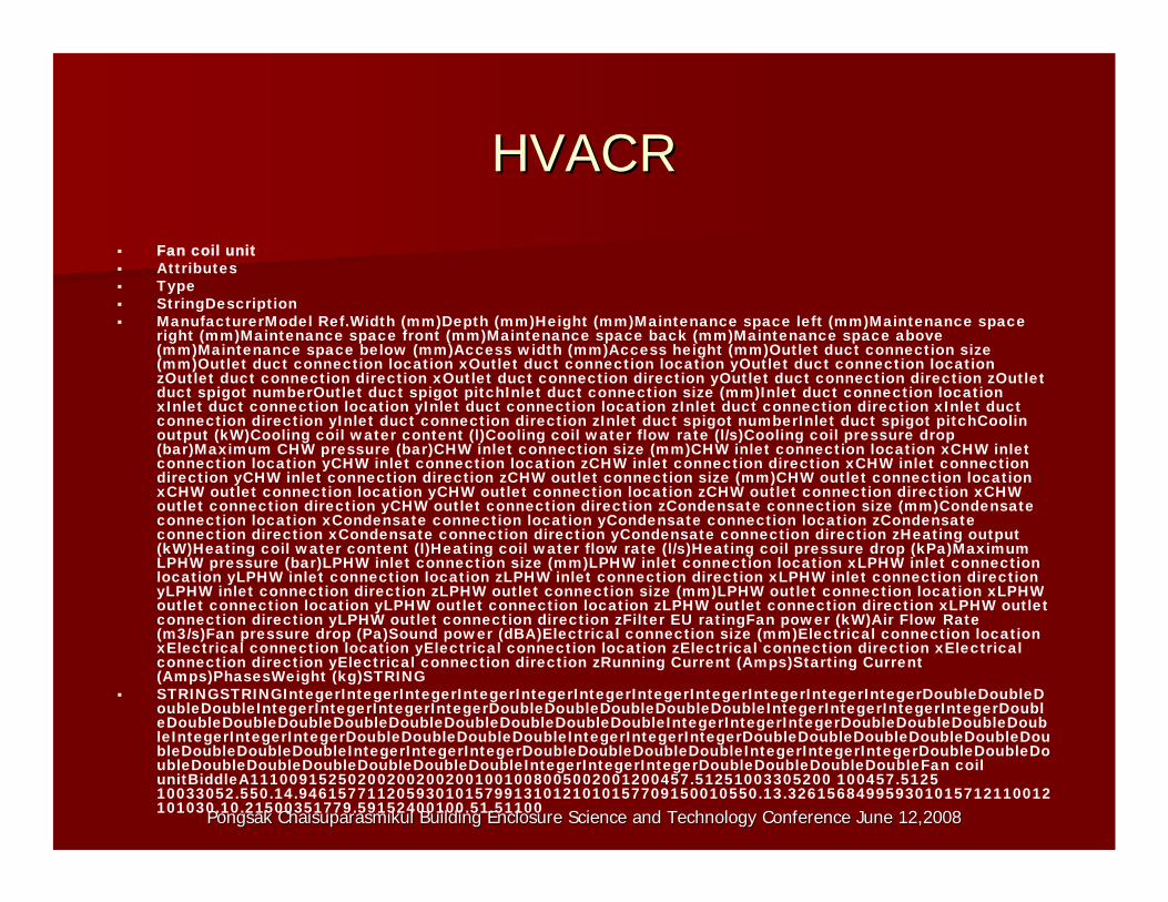
HVACRHVACR Fan coil unit Attributes Type StringDescription ManufacturerModel Ref.Width (mm)Depth (mm)Height (mm)Maintenance space left (mm)Maintenance space
right (mm)Maintenance space front (mm)Maintenance space back (mm)Maintenance space above (mm)Maintenance space below (mm)Access width (mm)Access height (mm)Outlet duct connection size(mm)Outlet duct connection location xOutlet duct connection location yOutlet duct connection location zOutlet duct connection direction xOutlet duct connection direction yOutlet duct connection direction zOutletduct spigot numberOutlet duct spigot pitchInlet duct connection size (mm)Inlet duct connection location xInlet duct connection location yInlet duct connection location zInlet duct connection direction xInlet duct connection direction yInlet duct connection direction zInlet duct spigot numberInlet duct spigot pitchCoolinoutput (kW)Cooling coil water content (l)Cooling coil water flow rate (l/s)Cooling coil pressure drop(bar)Maximum CHW pressure (bar)CHW inlet connection size (mm)CHW inlet connection location xCHW inletconnection location yCHW inlet connection location zCHW inlet connection direction xCHW inlet connection direction yCHW inlet connection direction zCHW outlet connection size (mm)CHW outlet connection location xCHW outlet connection location yCHW outlet connection location zCHW outlet connection direction xCHWoutlet connection direction yCHW outlet connection direction zCondensate connection size (mm)Condensateconnection location xCondensate connection location yCondensate connection location zCondensateconnection direction xCondensate connection direction yCondensate connection direction zHeating output(kW)Heating coil water content (l)Heating coil water flow rate (l/s)Heating coil pressure drop (kPa)MaximumLPHW pressure (bar)LPHW inlet connection size (mm)LPHW inlet connection location xLPHW inlet connection location yLPHW inlet connection location zLPHW inlet connection direction xLPHW inlet connection direction yLPHW inlet connection direction zLPHW outlet connection size (mm)LPHW outlet connection location xLPHWoutlet connection location yLPHW outlet connection location zLPHW outlet connection direction xLPHW outlet connection direction yLPHW outlet connection direction zFilter EU ratingFan power (kW)Air Flow Rate (m3/s)Fan pressure drop (Pa)Sound power (dBA)Electrical connection size (mm)Electrical connection location xElectrical connection location yElectrical connection location zElectrical connection direction xElectricalconnection direction yElectrical connection direction zRunning Current (Amps)Starting Current (Amps)PhasesWeight (kg)STRING
STRINGSTRINGIntegerIntegerIntegerIntegerIntegerIntegerIntegerIntegerIntegerIntegerIntegerDoubleDoubleDoubleDoubleIntegerIntegerIntegerIntegerDoubleDoubleDoubleDoubleDoubleIntegerIntegerIntegerIntegerDoubleDoubleDoubleDoubleDoubleDoubleDoubleDoubleDoubleDoubleIntegerIntegerIntegerDoubleDoubleDoubleDoubleIntegerIntegerIntegerDoubleDoubleDoubleDoubleIntegerIntegerIntegerDoubleDoubleDoubleDoubleDoubleDoubleDoubleDoubleDoubleIntegerIntegerIntegerDoubleDoubleDoubleDoubleIntegerIntegerIntegerDoubleDoubleDoubleDoubleDoubleDoubleDoubleDoubleDoubleIntegerIntegerIntegerDoubleDoubleDoubleDoubleFan coil unitBiddleA111009152502002002002001001008005002001200457.51251003305200 100457.5125 10033052.550.14.94615771120593010157991310121010157709150010550.13.326156849959301015712110012 101030.10.21500351779.59152400100.51.51100
Pongsak Chaisuparasmikul Building Enclosure Science and TechnoloPongsak Chaisuparasmikul Building Enclosure Science and Technology Conference June 12,2008gy Conference June 12,2008
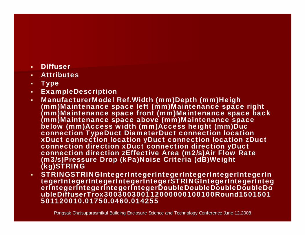
Diffuser Attributes Type ExampleDescription ManufacturerModel Ref.Width (mm)Depth (mm)Heigh
(mm)Maintenance space left (mm)Maintenance space right(mm)Maintenance space front (mm)Maintenance space back(mm)Maintenance space above (mm)Maintenance spacebelow (mm)Access width (mm)Access height (mm)Ducconnection TypeDuct DiameterDuct connection location xDuct connection location yDuct connection location zDuctconnection direction xDuct connection direction yDuctconnection direction zEffective Area (m2/s)Air Flow Rate(m3/s)Pressure Drop (kPa)Noise Criteria (dB)Weight(kg)STRING
STRINGSTRINGIntegerIntegerIntegerIntegerIntegerIntegerIntegerIntegerIntegerIntegerIntegerSTRINGIntegerIntegerIntegerIntegerIntegerIntegerIntegerDoubleDoubleDoubleDoubleDoubleDiffuserTrox300300300112000000100100Round1501501 501120010.01750.0460.014255
Pongsak Chaisuparasmikul Bu oloPongsak Chaisuparasmikul B
ti nt
ilding Enclosure Science and Technuilding Enclosure Science and Technology Conference June 12,2008gy Conference June 12,2008
SmarSmarttBIMBIM ObjectsObjects
Rules and parameters required todefine standard of its elements representation and relationshipwhich return the parameters. The rules define a set of standard solutions which can bring up to;
Naming Convention:Naming Convention:Building Product InformationBuilding Product InformationManufacturer:Manufacturer: Name of Equipment:Name of Equipment:Type: Model #Type: Model #Shared Parameter FileShared Parameter File Location:Location:LibraryLibrary\\ Shared txtShared txtParameters to Fill In:Parameters to Fill In:All Identity DataAll Identity DataURL.URL.Link all Informa oLink all Informa ionEquations for exampleEquations for example Lumens = Lumens Per Lamp *Lumens = Lumens Per Lamp *LampLamp QuantityQuantity
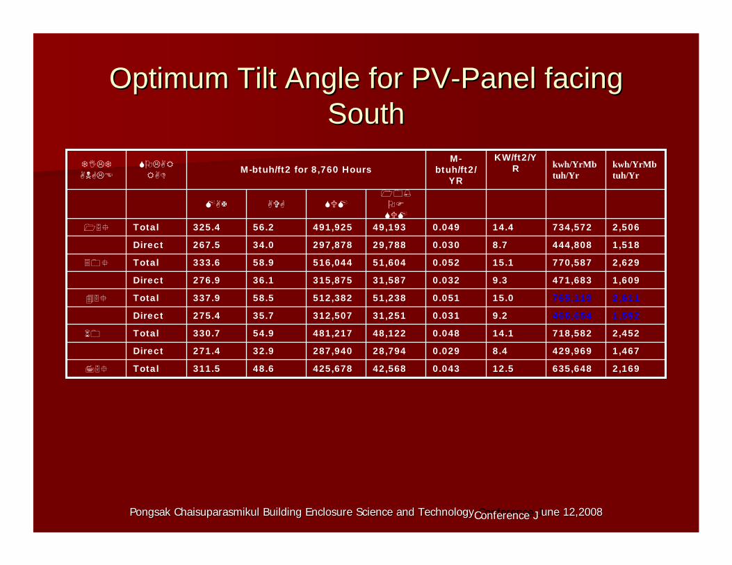
Optimum Tilt Angle for PVOptimum Tilt Angle for PV--Panel facingPanel facing SouthSouth
2,169635,64812.50.04342,568425,67848.6311.5Total
1,467429,9698.40.02928,794287,94032.9271.4Direct
2,452718,58214.10.04848,122481,21754.9330.7Total
1,592466,6549.20.03131,251312,50735.7275.4Direct
2,611765,11915.00.05151,238512,38258.5337.9Total
1,609471,6839.30.03231,587315,87536.1276.9Direct
2,629770,58715.10.05251,604516,04458.9333.6Total
1,518444,8088.70.03029,788297,87834.0267.5Direct
2,506734,57214.40.04949,193491,92556.2325.4Total
kwh/YrMb tuh/Yr
kwh/YrMb tuh/Yr
KW/ft2/Y R
Mbtuh/ft2/
YR M-btuh/ft2 for 8,760 Hours
Pongsak Chaisuparasmikul Building Enclosure Science and TechnoloPongsak Chaisuparasmikul Building Enclosure Science and Technology Conference Jgy une 12,20une 12, 080Conference J 20 8
’
Pongsak Chaisuparasmikul Building Enclosure Science and TechnoloPongsak Chaisuparasmikul Building Enclosure Science and Technology Conference June 12,2008gy Conference June 12,2008
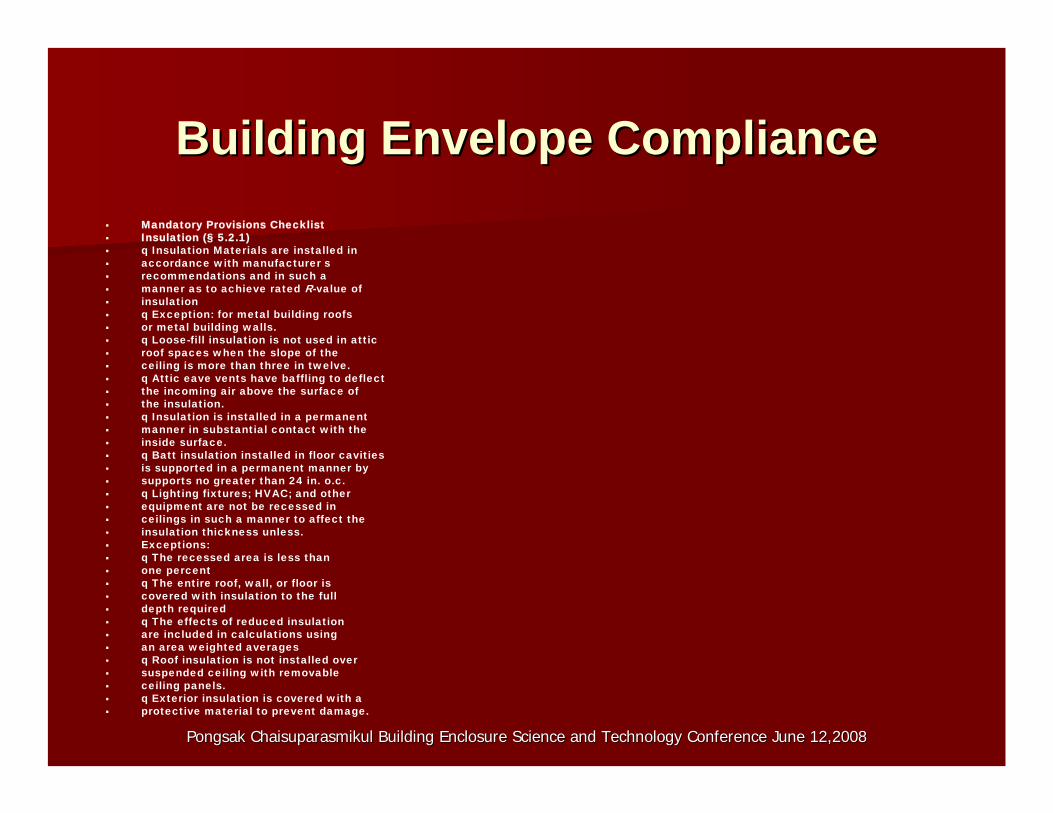
Building Envelope ComplianceBuilding Envelope Compliance Mandatory Provisions Checklist Insulation (§ 5.2.1) q Insulation Materials are installed in accordance with manufacturer s recommendations and in such a manner as to achieve rated R-value of insulation q Exception: for metal building roofs or metal building walls. q Loose-fill insulation is not used in attic roof spaces when the slope of the ceiling is more than three in twelve. q Attic eave vents have baffling to deflect the incoming air above the surface of the insulation. q Insulation is installed in a permanent manner in substantial contact with the inside surface. q Batt insulation installed in floor cavities is supported in a permanent manner by supports no greater than 24 in. o.c. q Lighting fixtures; HVAC; and other equipment are not be recessed in ceilings in such a manner to affect the insulation thickness unless. Exceptions: q The recessed area is less than one percent q The entire roof, wall, or floor is covered with insulation to the full depth required q The effects of reduced insulation are included in calculations using an area weighted averages q Roof insulation is not installed over suspended ceiling with removable ceiling panels. q Exterior insulation is covered with a protective material to prevent damage.
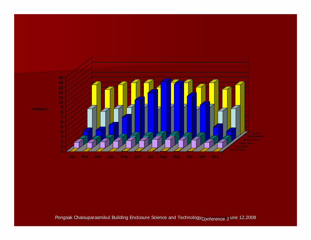
1514131211109000(Kwh) 87654 Light s
Equipment s Space C ool
3 2 Pump A ux
V ent .Fans Heat .Reject
1 0
Jan Feb Mar Apr May Jun Jul Aug Sep Oct Nov Dec
Pongsak Chaisuparasmikul Building Enclosure Science and TechnoloPongsak Chaisuparasmikul Building Enclosure Science and Technology Conference Jgy une 12,20une 12, 080Conference J 20 8
Pongsak Chaisuparasmikul Building Enclosure Science and TechnoloPongsak Chaisuparasmikul Building Enclosure Science and Technology Conference June 12,2008gy Conference June 12,2008
0
200
400
600
800
1000
1200
1400
1600
1800
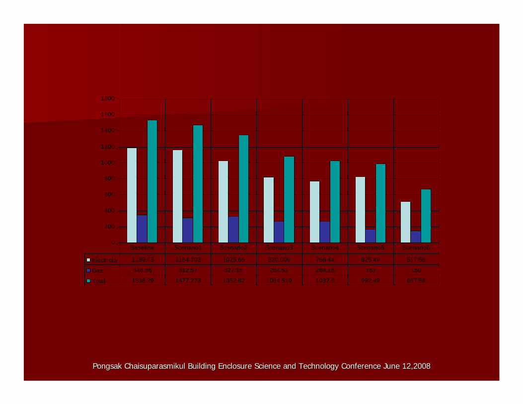
Electricity 1189.63 1164.703 1025.66 820.009 768.44 825.49 517.58
Gas 348.66 312.57 327.16 264.51 264.16 167 150
Total 1538.29 1477.273 1352.82 1084.519 1032.6 992.49 667.58
Baseline Scenario1 Scenario2 Scenario3 Scenario4 Scenario5 Scenario6