Embed Size (px)
Citation preview
National Aeronautics and Space Administration
Innovations that Power Our Future
2007 Annual Report to the Administrator
NASA Inventions & Contributions Board
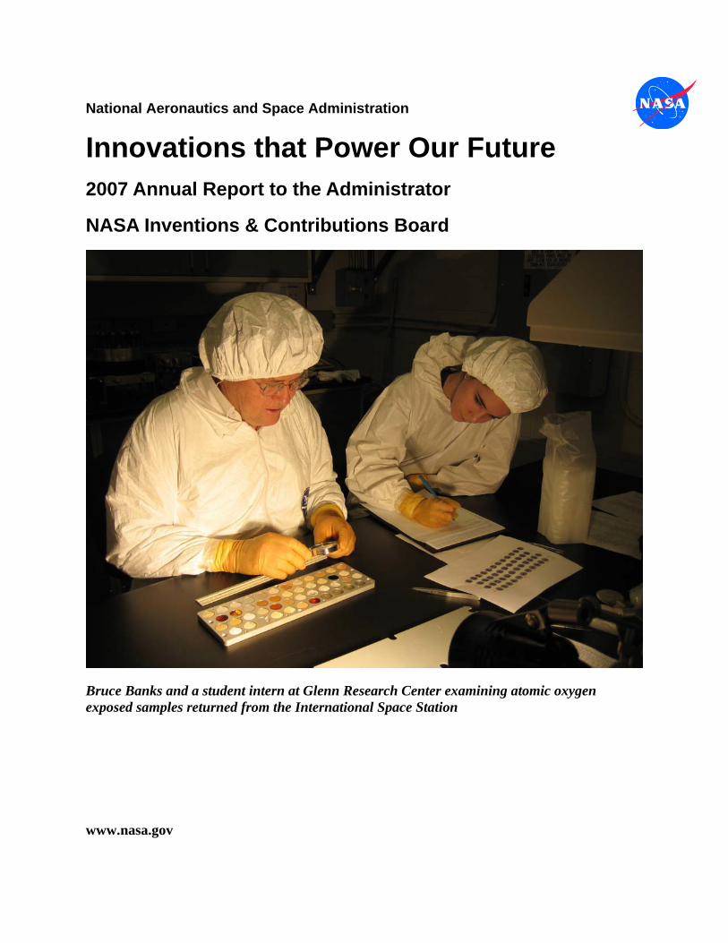
Bruce Banks and a student intern at Glenn Research Center examining atomic oxygen exposed samples returned from the International Space Station
www.nasa.gov
Innovations that Power Our Future
2007 Annual Report to the Administrator
NASA Inventions & Contributions Board
Index
Foreword Dr. Michael G. Ryschkewitsch, Chair, NASA Chief Engineer
Introduction Powering the Future
Background Innovation: Visionary Invention
Performance 2007 Awards Statistics and Metrics
Exceptional Cases 12 Paragons of Power
Invention of the Year Materials Which Will Shape Things to Come
The Board and Staff Facilitating Rewards for Great Ideas
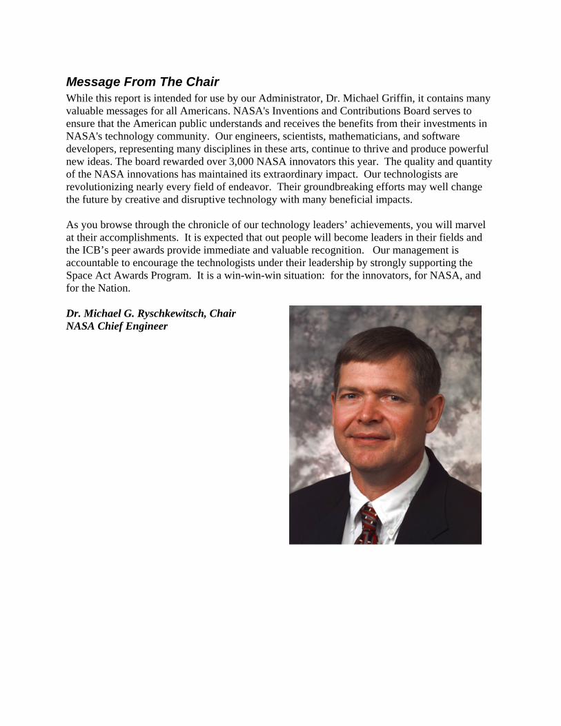
Message From The Chair While this report is intended for use by our Administrator, Dr. Michael Griffin, it contains many valuable messages for all Americans. NASA's Inventions and Contributions Board serves to ensure that the American public understands and receives the benefits from their investments in NASA's technology community. Our engineers, scientists, mathematicians, and software developers, representing many disciplines in these arts, continue to thrive and produce powerful new ideas. The board rewarded over 3,000 NASA innovators this year. The quality and quantity of the NASA innovations has maintained its extraordinary impact. Our technologists are revolutionizing nearly every field of endeavor. Their groundbreaking efforts may well change the future by creative and disruptive technology with many beneficial impacts. As you browse through the chronicle of our technology leaders’ achievements, you will marvel at their accomplishments. It is expected that out people will become leaders in their fields and the ICB’s peer awards provide immediate and valuable recognition. Our management is accountable to encourage the technologists under their leadership by strongly supporting the Space Act Awards Program. It is a win-win-win situation: for the innovators, for NASA, and for the Nation. Dr. Michael G. Ryschkewitsch, Chair NASA Chief Engineer
Introduction: Powering the Future The NASA Inventions and Contributions Board, established along with NASA in the Space Act of 1958, rewards NASA employee and contractors with recognition for significant contributions in science and technology to aeronautics and space activities. The Board makes recommendations to the Administrator for these awards, not to exceed $100,000 without congressional consent. Each year, the ICB awards about 3,000 individuals with cash and peer recognition. Also, on average, about 800 new technologies reported to NASA receive these awards. The 21-member Board, individually selected by the Administrator, reviews and judges cases of the highest value in significance, and some of these result in visionary inventions and contributions of enormous present and future impact. These innovations may power the future. Background – Innovation and Visionary Invention Over the last 49 years, NASA inventors have received over 98,000 awards from the ICB. Some of the best of these cases have been reported in the last five years of annual reports from the ICB, chronicled online at http://icb.nasa.gov/Annual_Report.html. The ICB Web site also archives a large number of exceptional cases dating back to 1990, including descriptions of the underlying technology, the key contributors and their employers, and case award amounts. Part of the ICB site honors the cases from 1991-2003 at http://icb.nasa.gov/excp.htm. The ICB has also funded awards for NASA’s Invention of the Year competition (see: http://icb.nasa.gov/invention.html) and Software of the Year award competition ( see: http://icb.nasa.gov/swoyinfo.html. The extraordinary impact of just a few of these cases on the U.S. economy and world commerce was documented in the 2003 ICB annual report at over $200 billion. The aggregate of all 98,000 awards that we have granted conservatively have contributed over half a trillion dollars in wealth to the economy and much enabling technology that will change how we work and live. As the reader may see from the descriptions online and this year’s exceptional cases, the future may bring many valuable spinoffs from NASA technology and science. Four of this year’s most promising contributions directly apply to medical technology. These should relieve suffering and provide early diagnosis benefiting millions of people.
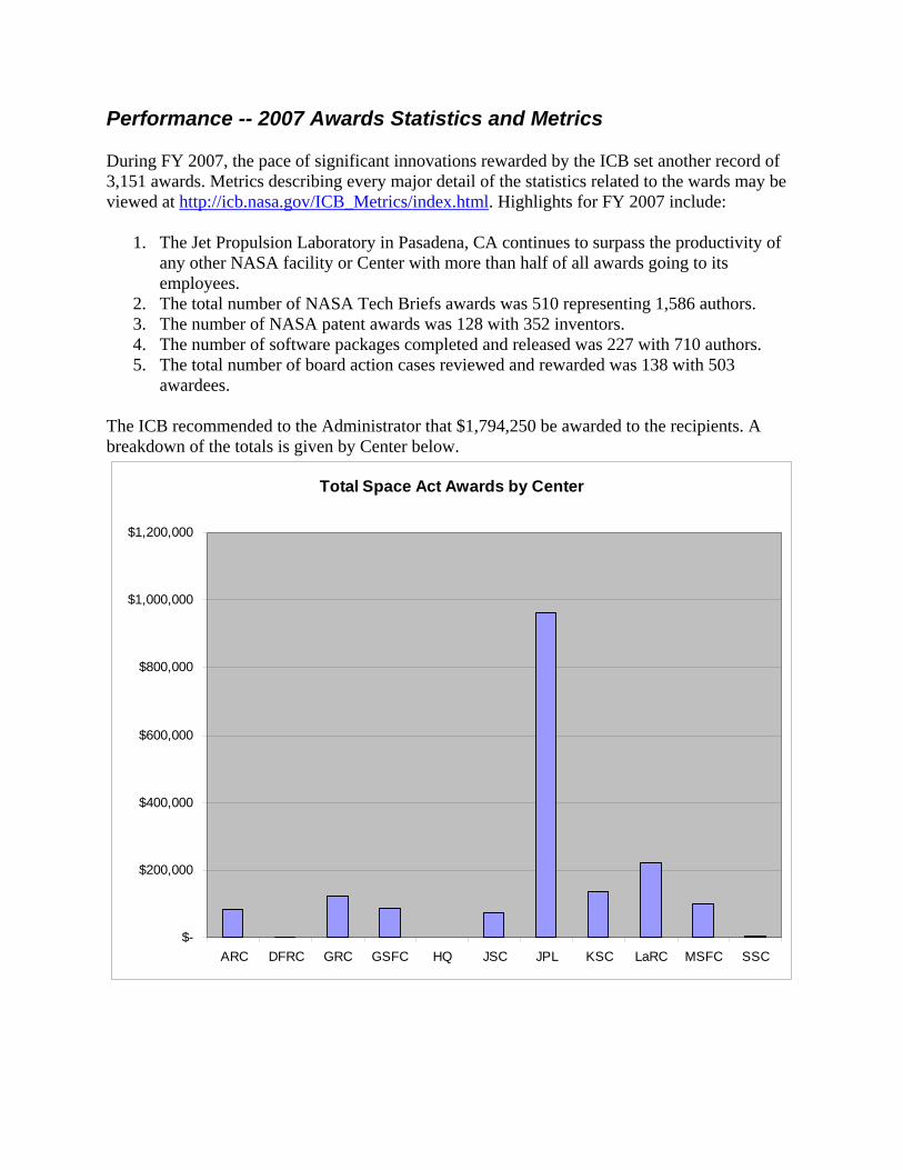
Performance -- 2007 Awards Statistics and Metrics During FY 2007, the pace of significant innovations rewarded by the ICB set another record of 3,151 awards. Metrics describing every major detail of the statistics related to the wards may be viewed at http://icb.nasa.gov/ICB_Metrics/index.html. Highlights for FY 2007 include:
1. The Jet Propulsion Laboratory in Pasadena, CA continues to surpass the productivity of any other NASA facility or Center with more than half of all awards going to its employees.
2. The total number of NASA Tech Briefs awards was 510 representing 1,586 authors. 3. The number of NASA patent awards was 128 with 352 inventors. 4. The number of software packages completed and released was 227 with 710 authors. 5. The total number of board action cases reviewed and rewarded was 138 with 503
awardees. The ICB recommended to the Administrator that $1,794,250 be awarded to the recipients. A breakdown of the totals is given by Center below.
Total Space Act Awards by Center
$-
$200,000
$400,000
$600,000
$800,000
$1,000,000
$1,200,000
ARC DFRC GRC GSFC HQ JSC JPL KSC LaRC MSFC SSC
Exceptional Cases: 12 Paragons of Power
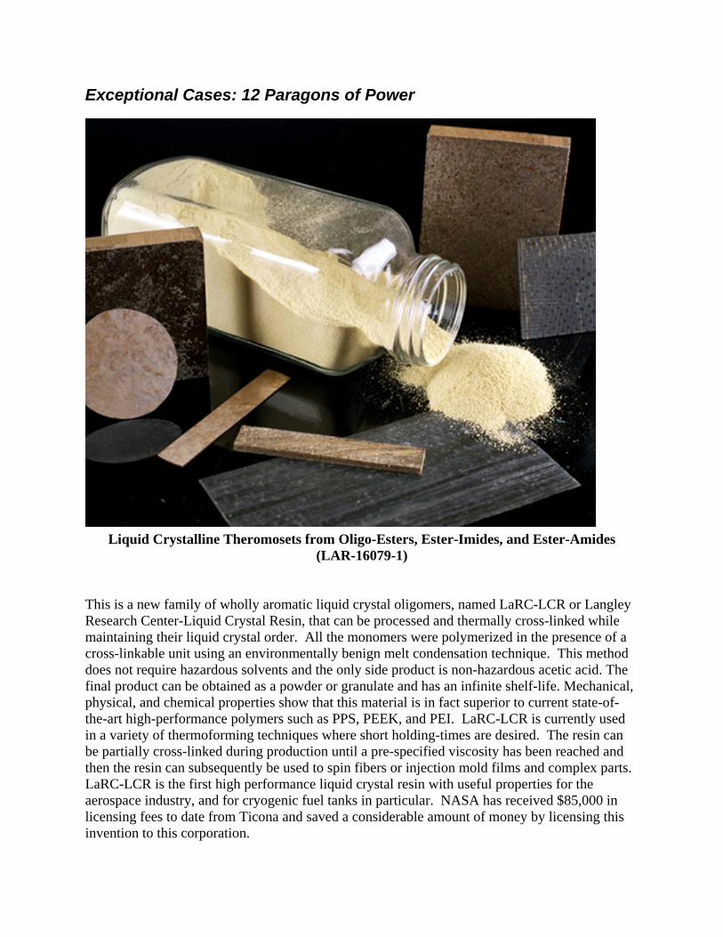
Liquid Crystalline Theromosets from Oligo-Esters, Ester-Imides, and Ester-Amides
(LAR-16079-1) This is a new family of wholly aromatic liquid crystal oligomers, named LaRC-LCR or Langley Research Center-Liquid Crystal Resin, that can be processed and thermally cross-linked while maintaining their liquid crystal order. All the monomers were polymerized in the presence of a cross-linkable unit using an environmentally benign melt condensation technique. This method does not require hazardous solvents and the only side product is non-hazardous acetic acid. The final product can be obtained as a powder or granulate and has an infinite shelf-life. Mechanical, physical, and chemical properties show that this material is in fact superior to current state-of-the-art high-performance polymers such as PPS, PEEK, and PEI. LaRC-LCR is currently used in a variety of thermoforming techniques where short holding-times are desired. The resin can be partially cross-linked during production until a pre-specified viscosity has been reached and then the resin can subsequently be used to spin fibers or injection mold films and complex parts. LaRC-LCR is the first high performance liquid crystal resin with useful properties for the aerospace industry, and for cryogenic fuel tanks in particular. NASA has received $85,000 in licensing fees to date from Ticona and saved a considerable amount of money by licensing this invention to this corporation.
Differential Radar Interferometry (NPO-17831-1)
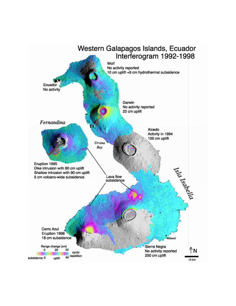
Differential Radar Interferometry is an enabling technology which will allow NASA to make new kinds of worldwide measurements that will better serve NASA's mission. The original publication by the named investigators used SEASAT data taken over California. Glacier motion was measured with NASA's SIR-C mission. The European ERS-1, ERS-2, ENVISAT, the Canadian RADARSAT, and the Japanese JERS have all been large users of this technology. Airborne experiments were conducted from the radar on the NASA DC-8 aircraft. First-stage experiments forming interferogram pairs were conducted with Magellan radar images of Venus. It was a core technology for proposed Space-Based Radar (SBR) program of NASA, DARPA, USAF/AFRL, and NRO. It is believed that NASA will also be a large user in future radar missions. Worldwide, many research groups are using and expanding on this technology, many of which (50+) are using a set of radar processing programs developed at JPL. Data from the above mentioned satellites have been used and published extensively for measuring earthquake displacements, ice sheet and glacier motions, coal mine, oil well and aquifer subsidence, volcano caldera swelling, ground surface disturbances, stability of dams with changing water loads, frost heaves, ground expansion from water-absorbing clays, and more. Google Scholar reports 7,960 hits from the key words ''radar interferometry change.” It has been very widely used, within many disciplines, as mentioned above. Scientific applications have appeared in seismology and seismic/tectonic modeling, primarily measurements of deformations along fault lines and as experimental verification of seismic modelling. In glaciology, the motion of glaciers has been monitored at a number of locations including Alaska, Antarctica, and Chile for environmental studies relating to global temperature change; in vulcanology, pre- and post- eruptive swelling has been observed, and unexpected volcanic activity was seen in the Galapagos Islands. Military applications include monitoring of underground structures. Commercial uses include monitoring of oilfield and aquifer subsidence due to water or oil extraction, which may be required to comply with environmental regulations. Aquifer subsidence in Las Vegas, Nevada has been measured at a rate that indicates serious future damage to municipal pipelines. It is believed that NASA will be a major user of this technology with a future radar mission. Natural resource companies, municipalities, and the State of California have indicated interest in future measurements for the purposes mentioned above. The usefulness will certainly increase with time, as the many research groups working in the area of radar interferometry find additional disciplines and applications. The biggest potential application is that the method will become useful for earthquake prediction. Additional uses include assessment of glacier growth and decay for climate change studies, and prediction and environmental characterization of volcanic eruptions, including mass displacement of atmospheric particulates and lava. The above-described methods, whether used for scientific understanding or commercial application often cannot be performed in any other way.
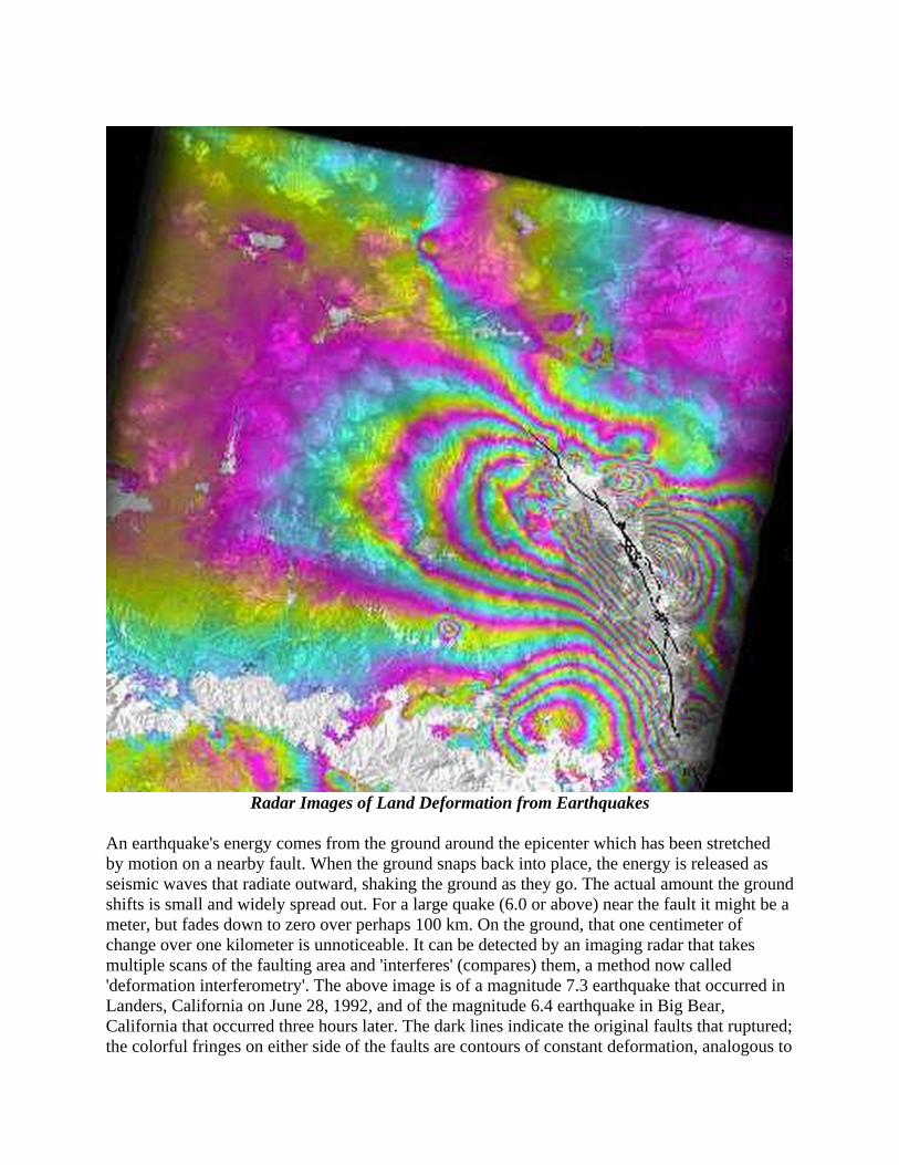
Radar Images of Land Deformation from Earthquakes
An earthquake's energy comes from the ground around the epicenter which has been stretched by motion on a nearby fault. When the ground snaps back into place, the energy is released as seismic waves that radiate outward, shaking the ground as they go. The actual amount the ground shifts is small and widely spread out. For a large quake (6.0 or above) near the fault it might be a meter, but fades down to zero over perhaps 100 km. On the ground, that one centimeter of change over one kilometer is unnoticeable. It can be detected by an imaging radar that takes multiple scans of the faulting area and 'interferes' (compares) them, a method now called 'deformation interferometry'. The above image is of a magnitude 7.3 earthquake that occurred in Landers, California on June 28, 1992, and of the magnitude 6.4 earthquake in Big Bear, California that occurred three hours later. The dark lines indicate the original faults that ruptured; the colorful fringes on either side of the faults are contours of constant deformation, analogous to

topographic contours. The large bullseye of color in the lower third of the image is formed by the deformation contours associated with the Big Bear event. The small bullseye below the center of the image is from an aftershock. The two areas with no color are the San Gabriel Mountains and the San Bernardino Mountains; interferometry sometimes breaks down, as here, in steep or mountainous areas. The Cajon Pass, which is less steep, appears as the blue diagonal line separating the two mountain ranges.
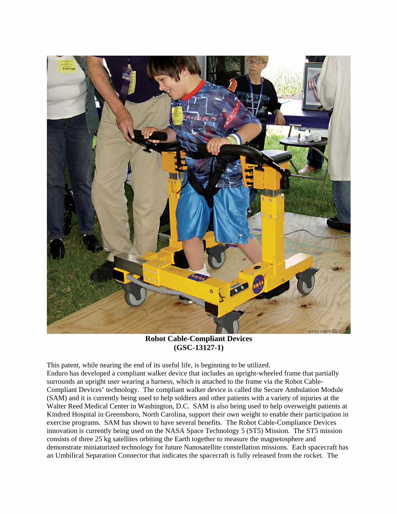
Robot Cable-Compliant Devices
(GSC-13127-1) This patent, while nearing the end of its useful life, is beginning to be utilized. Enduro has developed a compliant walker device that includes an upright-wheeled frame that partially surrounds an upright user wearing a harness, which is attached to the frame via the Robot Cable-Compliant Devices’ technology. The compliant walker device is called the Secure Ambulation Module (SAM) and it is currently being used to help soldiers and other patients with a variety of injuries at the Walter Reed Medical Center in Washington, D.C. SAM is also being used to help overweight patients at Kindred Hospital in Greensboro, North Carolina, support their own weight to enable their participation in exercise programs. SAM has shown to have several benefits. The Robot Cable-Compliance Devices innovation is currently being used on the NASA Space Technology 5 (ST5) Mission. The ST5 mission consists of three 25 kg satellites orbiting the Earth together to measure the magnetosphere and demonstrate miniaturized technology for future Nanosatellite constellation missions. Each spacecraft has an Umbilical Separation Connector that indicates the spacecraft is fully released from the rocket. The
Connector is positioned by a compliant mount which possesses a high tolerance for misalignment, and allows the spacecraft to separate smoothly. The Compliant Mount is an alternate embodiment of the Robot Cable-Compliance Devices technology.
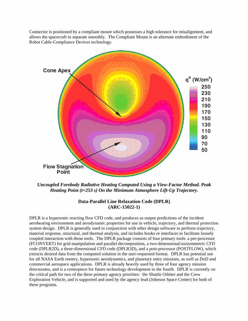
Uncoupled Forebody Radiative Heating Computed Using a View-Factor Method. Peak
Heating Point (t=253 s) On the Minimum Atmosphere Lift-Up Trajectory.
Data-Parallel Line Relaxation Code (DPLR) (ARC-15022-1)
DPLR is a hypersonic reacting flow CFD code, and produces as output predictions of the incident aeroheating environment and aerodynamic properties for use in vehicle, trajectory, and thermal protection system design. DPLR is generally used in conjunction with other design software to perform trajectory, material response, structural, and thermal analysis, and includes hooks or interfaces to facilitate loosely coupled interaction with those tools. The DPLR package consists of four primary tools: a pre-processor (FCONVERT) for grid manipulation and parallel decomposition, a two-dimensional/axisymmetric CFD code (DPLR2D), a three-dimensional CFD code (DPLR3D), and a post-processor (POSTFLOW), which extracts desired data from the computed solution in the user-requested format. DPLR has potential use for all NASA Earth reentry, hypersonic aerodynamics, and planetary entry missions, as well as DoD and commercial aerospace applications. DPLR is already heavily used by three of four agency mission directorates, and is a centerpiece for future technology development in the fourth. DPLR is currently on the critical path for two of the three primary agency priorities: the Shuttle Orbiter and the Crew Exploration Vehicle, and is supported and used by the agency lead (Johnson Space Center) for both of these programs.
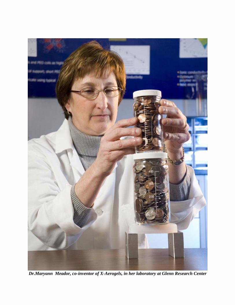
Dr.Maryann Meador, co-inventor of X-Aerogels, in her laboratory at Glenn Research Center
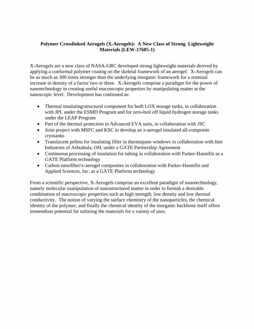
Polymer Crosslinked Aerogels (X-Aerogels): A New Class of Strong Lightweight Materials (LEW-17685-1)
X-Aerogels are a new class of NASA-GRC developed strong lightweight materials derived by applying a conformal polymer coating on the skeletal framework of an aerogel. X-Aerogels can be as much as 300 times stronger than the underlying inorganic framework for a nominal increase in density of a factor two or three. X-Aerogels comprise a paradigm for the power of nanotechnology in creating useful macroscopic properties by manipulating matter at the nanoscopic level. Development has continued as:
• Thermal insulating/structural component for both LOX storage tanks, in collaboration with JPL under the ESMD Program and for zero-boil off liquid hydrogen storage tanks under the LEAP Program
• Part of the thermal protection in Advanced EVA suits, in collaboration with JSC • Joint project with MSFC and KSC to develop an x-aerogel insulated all-composite
cryotanks • Translucent pellets for insulating filler in thermopane windows in collaboration with Iten
Industries of Ashtabula, OH, under a GATE Partnership Agreement • Continuous processing of insulation for tubing in collaboration with Parker-Hannifin as a
GATE Platform technology • Carbon nanofiber/x-aerogel composites in collaboration with Parker-Hannifin and
Applied Sciences, Inc. as a GATE Platform technology From a scientific perspective, X-Aerogels comprise an excellent paradigm of nanotechnology, namely molecular manipulation of nanostructured matter in order to furnish a desirable combination of macroscopic properties such as high strength, low density and low thermal conductivity. The notion of varying the surface chemistry of the nanoparticles, the chemical identity of the polymer, and finally the chemical identity of the inorganic backbone itself offers tremendous potential for tailoring the materials for a variety of uses.
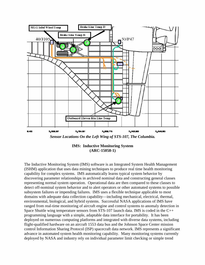
Sensor Locations On the Left Wing of STS-107, The Columbia.
IMS: Inductive Monitoring System
(ARC-15058-1) The Inductive Monitoring System (IMS) software is an Integrated System Health Management (ISHM) application that uses data mining techniques to produce real time health monitoring capability for complex systems. IMS automatically learns typical system behavior by discovering parameter relationships in archived nominal data and constructing general classes representing normal system operation. Operational data are then compared to these classes to detect off-nominal system behavior and to alert operators or other automated systems to possible subsystem failures or impending failures. IMS uses a flexible technique applicable to most domains with adequate data collection capability—including mechanical, electrical, thermal, environmental, biological, and hybrid systems. Successful NASA applications of IMS have ranged from real-time monitoring of aircraft engine and control systems to anomaly detection in Space Shuttle wing temperature sensors from STS-107 launch data. IMS is coded in the C++ programming language with a simple, adaptable data interface for portability. It has been deployed on numerous computing platforms and integrated with diverse data systems, including flight-qualified hardware on an aircraft 1553 data bus and the Johnson Space Center mission control Information Sharing Protocol (ISP) spacecraft data network. IMS represents a significant advance in automated system health monitoring capability. Many monitoring systems currently deployed by NASA and industry rely on individual parameter limit checking or simple trend
analysis to detect potentially hazardous off-nominal system performance. IMS augments that capability with a sensor fusion approach that analyzes relationships between several parameters in order to detect subtle variations in system performance that may not be noticed in single parameters. This sensor fusion allows IMS to detect possible problems before individual parameter limits are exceeded and provide an earlier alert to system operators. Since IMS monitoring knowledge bases are built automatically from nominal system data, it is possible to produce an advanced health monitoring capability relatively quickly without the time and effort required for simulation-based or rule-based monitoring system development. In many cases, a new IMS monitoring knowledge base can be produced within minutes or hours. The rapid learning capability of IMS also allows users to quickly produce a focused analysis of relevant system parameters in response to a system anomaly, or easily reconfigure their monitoring system in the event of a sensor or equipment failure. Because IMS system knowledge is derived from archived data, it also provides an historical perspective on system operations and can discover and highlight differences between current and historic system behavior.
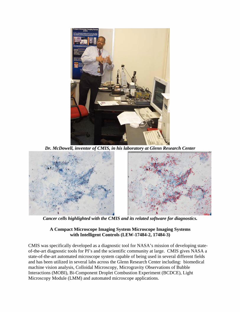
Dr. McDowell, inventor of CMIS, in his laboratory at Glenn Research Center
Cancer cells highlighted with the CMIS and its related software for diagnostics.
A Compact Microscope Imaging System Microscope Imaging Systems
with Intelligent Controls (LEW-17484-2, 17484-3) CMIS was specifically developed as a diagnostic tool for NASA’s mission of developing state-of-the-art diagnostic tools for PI’s and the scientific community at large. CMIS gives NASA a state-of-the-art automated microscope system capable of being used in several different fields and has been utilized in several labs across the Glenn Research Center including: biomedical machine vision analysis, Colloidal Microscopy, Microgravity Observations of Bubble Interactions (MOBI), Bi-Component Droplet Combustion Experiment (BCDCE), Light Microscopy Module (LMM) and automated microscope applications.
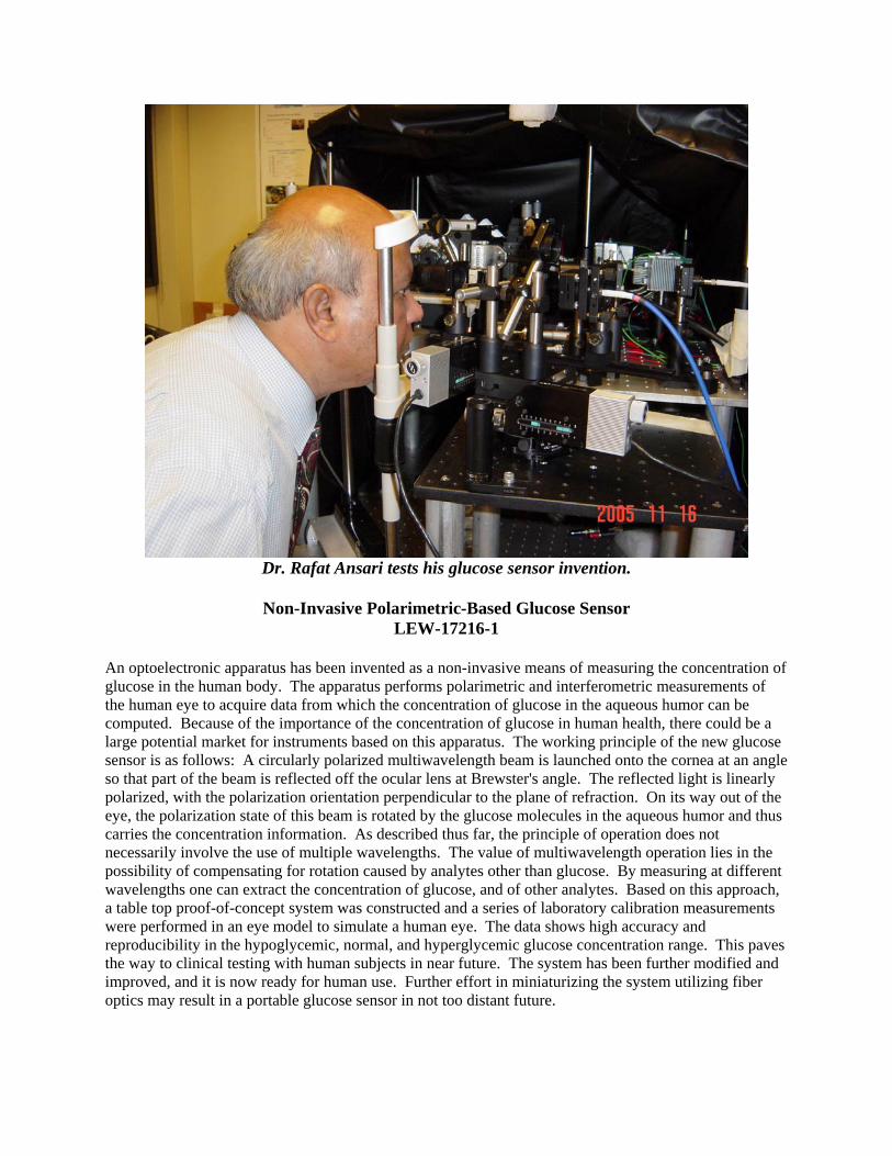
Dr. Rafat Ansari tests his glucose sensor invention.
Non-Invasive Polarimetric-Based Glucose Sensor
LEW-17216-1 An optoelectronic apparatus has been invented as a non-invasive means of measuring the concentration of glucose in the human body. The apparatus performs polarimetric and interferometric measurements of the human eye to acquire data from which the concentration of glucose in the aqueous humor can be computed. Because of the importance of the concentration of glucose in human health, there could be a large potential market for instruments based on this apparatus. The working principle of the new glucose sensor is as follows: A circularly polarized multiwavelength beam is launched onto the cornea at an angle so that part of the beam is reflected off the ocular lens at Brewster's angle. The reflected light is linearly polarized, with the polarization orientation perpendicular to the plane of refraction. On its way out of the eye, the polarization state of this beam is rotated by the glucose molecules in the aqueous humor and thus carries the concentration information. As described thus far, the principle of operation does not necessarily involve the use of multiple wavelengths. The value of multiwavelength operation lies in the possibility of compensating for rotation caused by analytes other than glucose. By measuring at different wavelengths one can extract the concentration of glucose, and of other analytes. Based on this approach, a table top proof-of-concept system was constructed and a series of laboratory calibration measurements were performed in an eye model to simulate a human eye. The data shows high accuracy and reproducibility in the hypoglycemic, normal, and hyperglycemic glucose concentration range. This paves the way to clinical testing with human subjects in near future. The system has been further modified and improved, and it is now ready for human use. Further effort in miniaturizing the system utilizing fiber optics may result in a portable glucose sensor in not too distant future.
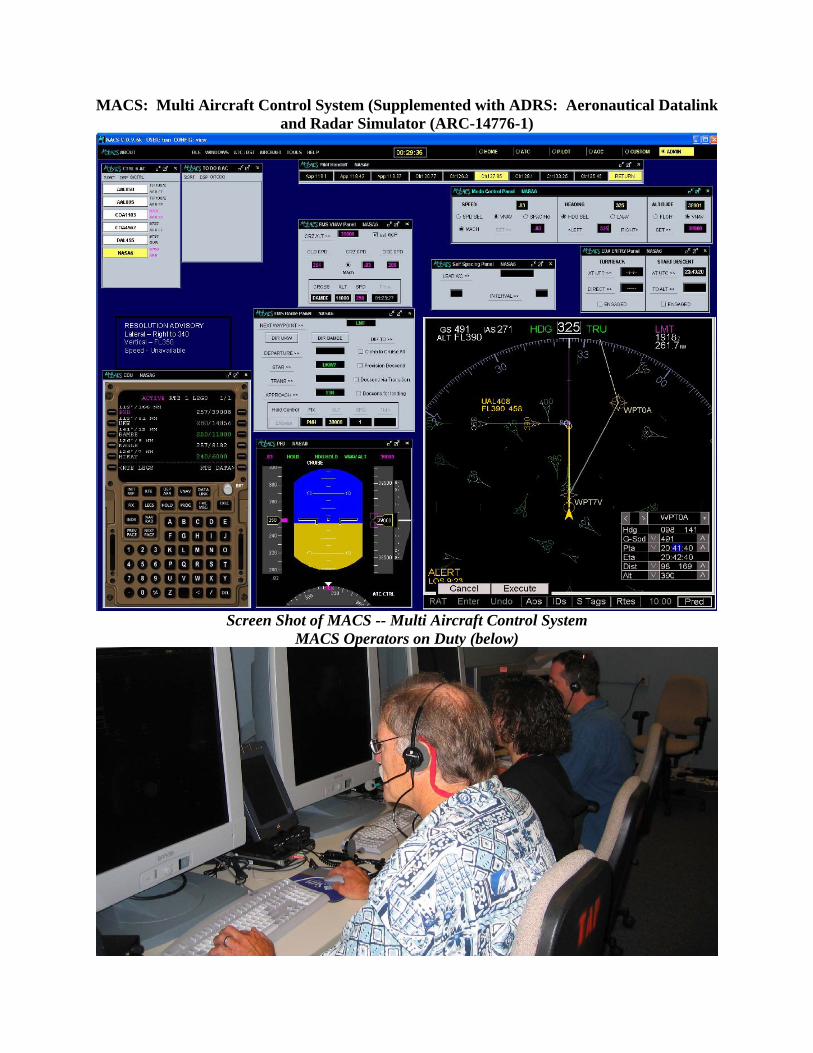
MACS: Multi Aircraft Control System (Supplemented with ADRS: Aeronautical Datalink and Radar Simulator (ARC-14776-1)
Screen Shot of MACS -- Multi Aircraft Control System
MACS Operators on Duty (below)
The Multi Aircraft Control System (MACS) with its networking supplement Aeronautical Datalink and Radar Simulator (ADRS) represents a most capable, versatile, and cost-effective environment for rapid prototyping, controller and pilot-in-the-loop simulation, and evaluation of current and future air/ground operations for the National Airspace System. The existing suite of capabilities allows researchers to configure a wide range of air traffic environments, from accurately emulating current day operations to simulating many of the operations envisioned for the Next Generation Air Transportation System (NGATS) as well as the transitional stages between now and then. In order to evaluate envisioned operational environments an unlimited number of MACS operator stations can be configured and connected via the ADRS networking infrastructure. These operator stations include high fidelity air traffic controller workstations in the oceanic, enroute and terminal domains, medium fidelity “glass cockpit” flight decks for confederate pilots and flight crew participants, as well as experimenter, observer, and analyst stations. The MACS built-in scenario and target generation capabilities can be used to generate and run rich traffic problems tailored to specific challenges such as high volume, weather, and various aircraft equipage levels that are designed to excite specific properties of the envisioned air traffic environment. The integrated comprehensive and flexible data collection system enables data analysis of all quantitative measures of interest. The primary use of the MACS/ADRS software is for evaluating future air traffic operational concepts. A simulation consisting of MACS and ADRS software represents a comprehensive test environment for experiments focusing on air traffic control operations, controller/automation integration and air/ground integration issues covering regional airspace problems, such as individual areas within Air Route Traffic Control Centers (ARTCCs) and Terminal Radar Approach Control TRACON. Some experiments require additional high fidelity pilot workstations or flight deck capabilities, such as full mission flight simulators or experimental cockpit displays of traffic information (CDTI), some cover additional domains, like airport surface and tower operations or NAS-wide traffic management. In any of the cases the ADRS provides connectivity to other simulation environments. CDTIs can be plugged into a MACS flight deck, full mission simulators can take over individual aircraft, other airspace simulations can feed parts or all of the traffic into MACS/ADRS. When connected the MACS/ADRS based simulation acts in concert with all other simulators, being able to interact, take over and release control of any aircraft at any time.
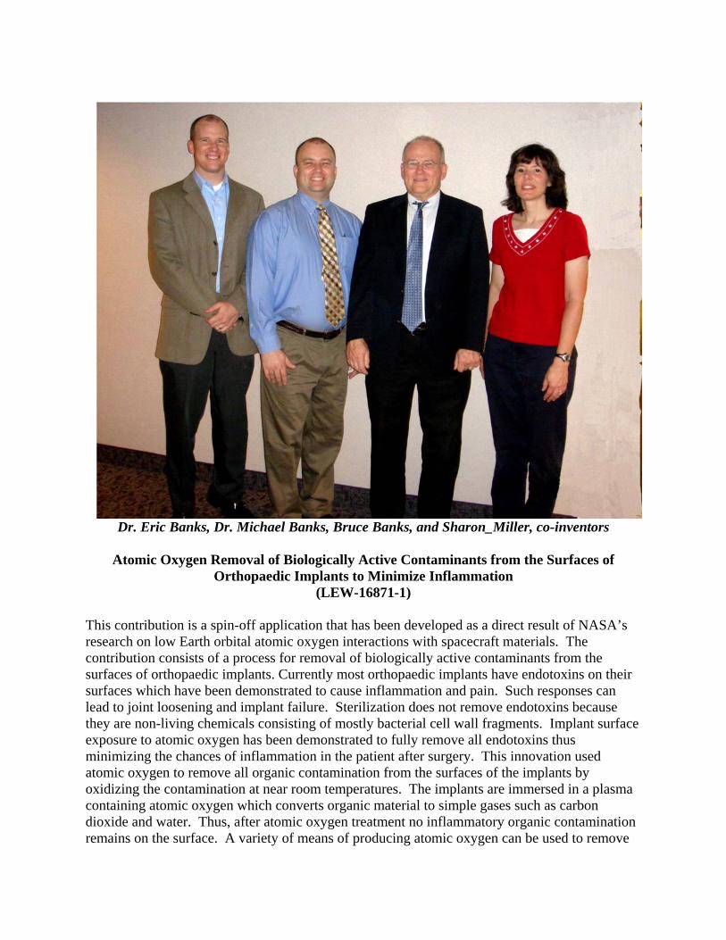
Dr. Eric Banks, Dr. Michael Banks, Bruce Banks, and Sharon_Miller, co-inventors
Atomic Oxygen Removal of Biologically Active Contaminants from the Surfaces of
Orthopaedic Implants to Minimize Inflammation (LEW-16871-1)
This contribution is a spin-off application that has been developed as a direct result of NASA’s research on low Earth orbital atomic oxygen interactions with spacecraft materials. The contribution consists of a process for removal of biologically active contaminants from the surfaces of orthopaedic implants. Currently most orthopaedic implants have endotoxins on their surfaces which have been demonstrated to cause inflammation and pain. Such responses can lead to joint loosening and implant failure. Sterilization does not remove endotoxins because they are non-living chemicals consisting of mostly bacterial cell wall fragments. Implant surface exposure to atomic oxygen has been demonstrated to fully remove all endotoxins thus minimizing the chances of inflammation in the patient after surgery. This innovation used atomic oxygen to remove all organic contamination from the surfaces of the implants by oxidizing the contamination at near room temperatures. The implants are immersed in a plasma containing atomic oxygen which converts organic material to simple gases such as carbon dioxide and water. Thus, after atomic oxygen treatment no inflammatory organic contamination remains on the surface. A variety of means of producing atomic oxygen can be used to remove
the endotoxins and other organic contaminants (such as traces of cutting tool fluids). Osteoarthritis effects between 20% and 30% of the people in the USA over 70 years old and 32 million people of all ages. There are 350,000 hip fractures in the USA each year that require orthopaedic implants for repair. It is estimated that by the year 2050 there will be 1,800 hip fractures per day that will require surgery. Almost all such surgeries will require implantation of orthopaedic devices that are currently contaminated with biologically active chemicals which can cause inflammation. The quality of life and financial cost associated with inflammation resulting from implant contamination is enormous. As the average life expectancy increases along with weight of Americans the incidence of restorative orthopaedic surgery will obviously increase. Surveys indicate that the worldwide orthopaedic implant market was $4.5 billion in 2002 and is expected to be $7 billion in 2007. The quality of life improvements and reduction in corrective orthopaedic operations enabled by reduction in inflammation through use of atomic oxygen removal of biologically active contaminants would be significant. Especially if, as testing indicated ¾ of orthopaedic implants surfaces are contaminated with endotoxins.
Dr. Yoaz Bar-Sever, JPL Inventor of many GPS-related technologies
A Fix for the Global Positioning System Yaw Attitudes Problem
During Eclipse Seasons (NPO-19627-1)
Dr. Bar-Sever identified the root cause for degradation in the orbit determination of Global Positioning System (GPS) satellites during eclipse season. The root cause was diagnosed as a feature of the satellite onboard solar sensor, affecting the satellite attitude in an un-modelable manner. He proposed a software change onboard the satellite that mitigates the problem by introducing a fixed yaw bias. He then devised and coded algorithms to model the new satellite attitude resulting from implementation of the yaw bias. After the U.S. Air Force has implemented the yaw bias on the GPS satellites, as recommended, the new technique demonstrated the improvement to the GPS orbit determination. The innovation improves the performance of the GPS. GPS is a critical global infrastructure, a strategic national security asset, and an important scientific tool. The benefits from this innovation are, therefore, very broad. The strongest impact is on high end applications of GPS, such as improved ground positioning for natural hazard monitoring, improved orbit determination of altimetry satellites for better sea surface height determination, improved orbit determination for space imaging satellite, improved atmospheric sounding with GPS occultations for weather forecasting, and improved predictability of the GPS constellation in support of emergency geolocation of cell phone users.
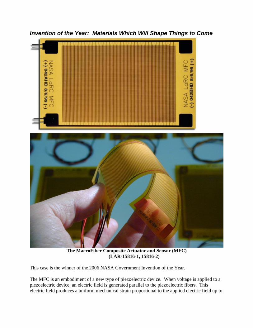
Invention of the Year: Materials Which Will Shape Things to Come
The MacroFiber Composite Actuator and Sensor (MFC)
(LAR-15816-1, 15816-2)
This case is the winner of the 2006 NASA Government Invention of the Year. The MFC is an embodiment of a new type of piezoelectric device. When voltage is applied to a piezoelectric device, an electric field is generated parallel to the piezoelectric fibers. This electric field produces a uniform mechanical strain proportional to the applied electric field up to
a saturation point. Conversely, when the device is mechanically strained, a voltage is produced in response to the magnitude and direction of the applied load. The MFC technology is a complete make over and refinement of earlier methods to enable the fabrication of piezoelectric actuators and sensors with increased performance, reliability, and manufacturability at reduced cost. For instance, rather than use expensive round piezoelectric fibers, the MFC uses commercial piezoelectric wafers that are diced into square fibers and placed, pre-aligned, directly onto commercially produced polyimide copper films. There is no direct handling of the piezo-material, no health issues with lead oxides and no fiber breakage. Additionally, the concepts used to make the MFC allows for the robust assembly of almost any commercial dielectric “smart” materials to be assembled into a low cost, durable, flexible, sealed package for use as both an actuator and sensor in a variety of shapes and sizes. When compared to standard piezoelectric systems, the MFC is much more durable and provides increased unidirectional control. Furthermore, the MFC is designed to be readily integrated into a system as an add-on component or integrated during manufacture. The MFC’s flat profile and use as a sensor and an actuator allows for use in critical or tight areas where other technologies with larger volumetric profiles cannot be used. This technology, in combination with the ability to self power wireless circuitry from the electricity generated from flexing the MFC, enables additional health monitoring application on complex rotating components, such as turbomachinery, or in remote areas, such as hazardous environments, where additional wiring and power sources can be extremely difficult to implement. MFC has been used experimentally on a number of NASA missions to prove concepts, including mitigation of buffeting of vertical stabilizers on aircraft, solar sails and inflatable space structures, morphing systems, structural health monitoring devices, vibration damping and noise cancellation strategies, structural shaping and stiffness control, aeroelelastic instability mitigation, and dozens of other active control solutions. It has also found commercial appplications in similar areas, most notably for reduction of vibration in automotive drive shafts for Volkswagon. The patents have been non-exclusively licensed in the U.S. to Smart Material Corporation (SMC) of Sarasota, Florida, who also holds exclusive license for overseas sales. Royalties to date from SMC total over $50,000 to NASA, about 17 percent for domestic sales.
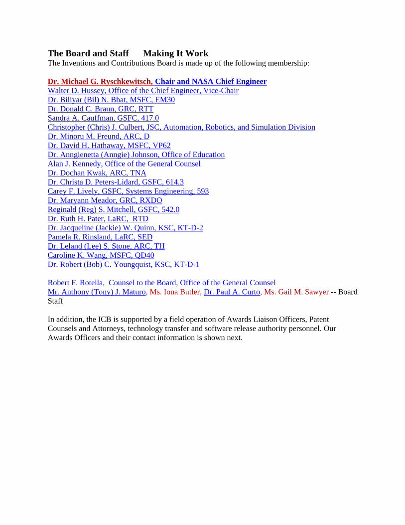
The Board and Staff Making It Work The Inventions and Contributions Board is made up of the following membership: Dr. Michael G. Ryschkewitsch, Chair and NASA Chief Engineer Walter D. Hussey, Office of the Chief Engineer, Vice-Chair Dr. Biliyar (Bil) N. Bhat, MSFC, EM30 Dr. Donald C. Braun, GRC, RTT Sandra A. Cauffman, GSFC, 417.0 Christopher (Chris) J. Culbert, JSC, Automation, Robotics, and Simulation Division Dr. Minoru M. Freund, ARC, D Dr. David H. Hathaway, MSFC, VP62 Dr. Anngienetta (Anngie) Johnson, Office of Education Alan J. Kennedy, Office of the General Counsel Dr. Dochan Kwak, ARC, TNA Dr. Christa D. Peters-Lidard, GSFC, 614.3 Carey F. Lively, GSFC, Systems Engineering, 593 Dr. Maryann Meador, GRC, RXDO Reginald (Reg) S. Mitchell, GSFC, 542.0 Dr. Ruth H. Pater, LaRC, RTD Dr. Jacqueline (Jackie) W. Quinn, KSC, KT-D-2 Pamela R. Rinsland, LaRC, SED Dr. Leland (Lee) S. Stone, ARC, TH Caroline K. Wang, MSFC, QD40 Dr. Robert (Bob) C. Youngquist, KSC, KT-D-1 Robert F. Rotella, Counsel to the Board, Office of the General Counsel Mr. Anthony (Tony) J. Maturo, Ms. Iona Butler, Dr. Paul A. Curto, Ms. Gail M. Sawyer -- Board Staff In addition, the ICB is supported by a field operation of Awards Liaison Officers, Patent Counsels and Attorneys, technology transfer and software release authority personnel. Our Awards Officers and their contact information is shown next.
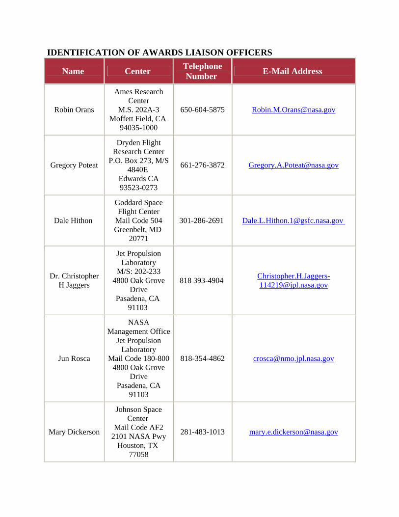
IDENTIFICATION OF AWARDS LIAISON OFFICERS
Name Center Telephone Number E-Mail Address
Robin Orans
Ames Research Center
M.S. 202A-3 Moffett Field, CA
94035-1000
650-604-5875 [email protected]
Gregory Poteat
Dryden Flight Research Center
P.O. Box 273, M/S 4840E
Edwards CA 93523-0273
661-276-3872 [email protected]
Dale Hithon
Goddard Space Flight Center
Mail Code 504 Greenbelt, MD
20771
301-286-2691 [email protected]
Dr. Christopher H Jaggers
Jet Propulsion Laboratory
M/S: 202-233 4800 Oak Grove
Drive Pasadena, CA
91103
818 393-4904 [email protected]
Jun Rosca
NASA Management Office
Jet Propulsion Laboratory
Mail Code 180-800 4800 Oak Grove
Drive Pasadena, CA
91103
818-354-4862 [email protected]
Mary Dickerson
Johnson Space Center
Mail Code AF2 2101 NASA Pwy
Houston, TX 77058
281-483-1013 [email protected]
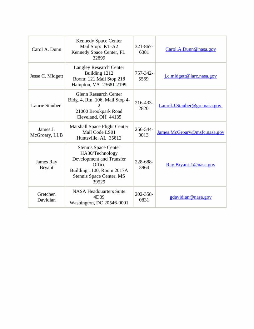
Carol A. Dunn
Kennedy Space Center Mail Stop: KT-A2
Kennedy Space Center, FL 32899
321-867-6381 [email protected]
Jesse C. Midgett
Langley Research Center Building 1212
Room: 121 Mail Stop 218 Hampton, VA 23681-2199
757-342-5569 [email protected]
Laurie Stauber
Glenn Research Center Bldg. 4, Rm. 106, Mail Stop 4-
2 21000 Brookpark Road Cleveland, OH 44135
216-433-2820 [email protected]
James J. McGroary, LLB
Marshall Space Flight Center Mail Code LS01
Huntsville, AL 35812
256-544-0013 [email protected]
James Ray Bryant
Stennis Space Center HA30/Technology
Development and Transfer Office
Building 1100, Room 2017A Stennis Space Center, MS
39529
228-688-3964 [email protected]
Gretchen Davidian
NASA Headquarters Suite 4D39
Washington, DC 20546-0001
202-358-0831 [email protected]


![Experiencing the Solar System Figure 1: NASA. (n.d.). Our solar system [Web]. Retrieved from](https://img.pdfslide.us/doc/110x75/56649c755503460f94929803/experiencing-the-solar-system-figure-1-nasa-nd-our-solar-system-web.jpg)