Embed Size (px)
Citation preview
Innovations in Navigation Lock Design
InCom WG29 Members
RIGO Philippe – Chairman (1)
and BÖDEFELD Jörg (DE), BOS Jan (NL), CLARKSON John (USA), DALY Fabrice (Fr),
FERNANDEZ José (Spain), HIJDRA Arjan (NL), HIVER Jean-Michel (BE), HOLM Olli (Fin), HUNTER Peter (UK), MILLER Dale (USA), PICHON Nicolas (Fr),
POLIGOT-PITSCH Stephanie (Fr), SARGHIUTA Radu (RO), TARPEY Michael (USA), THOMAS Rik (BE), THORENZ Carsten (DE), WU Peng (CN)
(1) University of Liège - FNRS (National Funds of Scientific Research of Belgium), ANAST, BELGIUM
[email protected] ABSTRACT
InCom Working Group 29 of PIANC (WG29) is conducting a comprehensive review of the current state of the art of the design and construction of navigation locks. Recent projects are listed, reviewed and analyzed, and guidelines for future studies at the design stage are established. Maintenance and operational requirements are also discussed.
The focus of the WG concerns the design objectives and the optimization goals that govern
the design of a lock, with an emphasis on recent innovative concepts and technologies used to design and build navigation locks.
This paper presents the content of the report and describes the most important issues that are
currently being discussed by the WG29. This presentation is being made at PIANC AGA 2008 Beijing Seminar to invite valuable feedback from the international community. We want to avoid a missing key issue in our report. 1. INTRODUCTION
Locks are key structures for the development of navigation in natural rivers, where weirs control water levels to allow navigation, and in artificial canals. Locks are also strategic infrastructures for port development. In low-lying countries, such as the Netherlands and Belgium, locks are structures in dikes and have an important function in flood defence.
In 1986, PIANC compiled a comprehensive report of 445 pages on Locks (PIANC, 1986). This
report is one of the few international reference guidelines for lock design prepared during the last 20 years and is considered a key reference by experts around the world. In 2006 PIANC decided that an update to this report to include innovations in design and construction that have occurred in the last 20 years would be beneficial and PIANC established a new Working Group to update of this famous report.
The new WG29 report on locks is a complement to the 1986 report. It focuses on innovative
techniques that have been developed since the earlier report was published. It covers all aspects of lock design but does not duplicate the material included in the former report if no significant
change occurs. Innovations and changes occurring since 1986 are the main target of the present report.
This report has three major parts. The first (Section 3) presents an exhaustive list of design
goals associated with locks. This section is important for decision makers who have to launch a new project. The second part (Section 4) reviews the design principles that must be considered by the designers. This section is methodology oriented. The third part (Section 5) is technically oriented. All major technical aspects (hydraulic, structure, foundations …) are reviewed, focussing on changes and innovations occurring since 1986. Perspectives and trends for the future are also considered. When appropriate, recommendations are provided.
Major changes since 1986 concern maintenance and operation aspects, and more specifically
which aspects should be included in the criteria as goals in the conceptual and design stages of a lock. Renovation and rehabilitation of existing locks are also key issues for the future.
The report (Section 2) also includes a series of project reviews of recent and planned lock
projects, including project descriptions and focussing on innovation.. 2 PROJECT REVIEWS
The WG has reviewed about 50 existing lock projects. A selection of reviews is included in the appendix of this paper. 3 DESIGN AND OPTIMIZATION GOALS
This section is a general introduction of the design objectives and optimization goals that govern the design of a lock. Sections 4 and 5 give the links between these objectives/goals and the technical aspects of the lock design (layout of hydraulic system, structure layout, construction mode, choice of equipment…).
The report documents, in more detail, the following main design objectives and optimization goals that govern the design of a lock:
- Reliability of the system, structures and the operations, - Reduced duration of a lock navigation cycle times, - Reduced water motions inducing ship displacement and mooring forces - Avoid water resource problems (minimise water use) - Saltwater intrusion - Reduced life cycle cost - Minimizing energy use - Avoid negative environmental impact - Minimize impacts to navigation traffic and surrounding community - Safety and Security
Whether a public or private company is concerned, the construction of new locks is a major challenge. Investments, occupation of land, and alteration of social, physical or economic “status quo”, are among the questions to consider before planning or starting work.

In addition to the technical and constructional aspects, there are the infrastructure management and planning aspects that have to be considered. Amongst these aspects, three points are particularly important:
- Selection of the optimum lock dimensions with regard to the expected market, the traffic trends and the evolution of vessel size,
- Safety risks caused by failures - Economic losses caused by any operational shutdowns due to failures or needs for
maintenance. The first step in the design of a lock is to write a reference document (terms of reference) with clear specifications and requirements based on a list of objectives (objective approach) or on a list of achievable functions (function approach).
For high locks (lift height of 20 to 30 m), current designs are nowadays quite close to the feasible physical limits of filling time, flow speed, allowable currents/waves, cavitation, and the structural capacity of the concrete side wall structure as well as the downstream gate. That is why the determination of relevant performance values (extreme values and allowable tolerances) is important. The various objectives can be in conflict and choices that are too ambitious can lead to excessive costs. The second step is to evaluate alternative technical design concepts based on previous experience or on new innovative studies and research. These concepts mainly concern:
- the type of structures (walls and floor), - the choice between a simple or a multiple lock - the use and configuration of water saving basins - the type of filling system (through the gates, short or long side culverts, through the
floor …) - the type of gates, depending on the dimensions of the lock, the type and number of ships,
the water-levels, etc. - various other technical points as the type, position and number of valves, bulkheads, and
other equipment. The third step is to optimize the design. Two approaches can be considered:
- A Series of Local Optimisations: Optimizing separately, various parts and components of the lock to obtain, after integration of these different components, an improved design/solution,
- Global Comparison: Comparing several global solutions (for example a U-shape lock chamber with separated saving basins, a filling system in the floor…).
The objective approach We differentiate between :
- the objectives of the waterway (particularly those having an influence on locks) - the objectives of the lock itself (mainly consequences of the waterway objectives, but
more technical and precise)
Generally a new waterway or its improvement is justified by economic or political objectives: to improve traffic flows, to allow growth of vessel numbers and dimensions, to develop economic activity, etc.

When the need for the project or improvement has been demonstrated, the waterway objectives must be precisely described by the owner with a set of “global performance indicators” that specifically define the use and the capacity of the system. This includes the vessels that will use the system and conditions under which they will use it. These performance indicators may be defined by:
- traffic (tonnage and type of ships) , - transit time on the new waterway - speed of the ships, - air clearance and water depth (or under keel clearance for the reference ship), - availability of the waterway (number of operating days/year, cumulated duration and
number of maintenance closures), - navigational safety , - maintenance requirements (available staff, available time and allocated budget), - reliability level (to define navigation availability and avoid failures), - acceptable impacts on environment and local population, including fish migration
(contribution to sustainable development), - cost (construction, maintenance and operation), including energy consumption (e.g.
pumping costs during lock operation), - hydraulic constraints upstream and downstream: max and min water level, maximum
wave amplitude induced by locking, maximum allowable current speed induced by locking. - minimize excavation or embankment volumes (more critical for canal projects), - safety against flooding.
In addition and particularly for canals, we have to consider water consumption of the
waterway including water losses (evaporation, infiltration...), and, for sea locks, saline water penetration. In addition to the above, specific lock design objectives include:
- lock dimensions (including clearance), - duration of lock cycle (filling time, gate operation time, ship entrance, etc.), - water consumption of the lock and water saving rate, - energy consumption, - operating time (12h or 24h/day...), - reliability of the lock operations with respect to mechanical equipment, - reliability of the lock with regard to climatic constraints (floods, ice, drought…) - maintenance constraints - maximum availability with regard to scheduled closures for maintenance (duration and
cost of maintenance, possibility of dewatering to obtain a dry lock, or possibility to do maintenance without dewatering )
- acceptable degree of risk in relation to the use of new technologies, - the project design life, - navigation safety and ship protections, - security of locks (access control), - maximum discharge in the adjacent reaches (induced by the filling/emptying), - maximum water slope in the lock during operation and limitation of water turbulence and
hawsers forces, - additional functions or objectives, for example:
o flood control may require discharge through the lock, o future lock extension.

As an example, the main objectives of the new Panama Canal expansion project (defined by the canal authority, ACP) are:
- The new locks are a demand driven system (increasing traffic), and its operating times determine the capacity of the system,
- Reliability is a major requirement, as any shutdown time means loss of income. - Maintenance shutdown has to be kept to a minimum. - Construction cost and whole life cost should be minimized. - Operation facilities and systems should be kept simple and reliable.
4 DESIGN PRINCIPLES & DESIGN METHODOLOGY
This section reviews the key points that must be considered in the early design stages of a lock or a new waterway, which are:
- Lock layout & Lock dimensions - Life cycle of a lock - Construction Modes or Methods - Layout of the hydraulic system - Lock structure concepts - Salt water intrusion, Ice Control, Communication, Security and Safety, …
4.1 DESIGN PRINCIPLES
This section introduces the major design principles and particularly focuses on the changes that occurred during the last 25 years, which are: “Risk based design” versus “Deterministic approach”
Nowadays a major project such as a lock must be justified by a variety of studies. The technical study (design aspect) and even its cost are no more than key points of a feasibility study. A series of other studies are also required:
- Impact on the environment: river flow, air, noise, fishes, birds and other animals, vegetation, groundwater…
- Risk analysis. In risk based analysis, risk is considered as the product of the cost of the failure by the probability of occurrence of the event which may cause the damage. Each significant accidental event must be considered and assessed. The level of any mitigation measures will be based on such a study. For instance: need for an emergency gate, need for redundant power supply, bank reinforcement to avoid flood …
- Consultation with the local communities and citizens. Eventually a group of key constituents will need to be organised.
- Economical analysis. Cost of course remains important and the investment must be justified. Projects with the highest ratio of benefits to cost should be considered for further study.
“Life cycle cost optimisation” versus “Least construction cost”:
Minimizing the cost of the lock is no longer the main objective of the designer. Now, the whole life cost should also be compared for the various technical alternatives (Ref. MarCom WG42 Report Life Cycle Management). Use of numerical modelling as design tool:
For each technical aspect, the actual state-of-art is presented with emphasis on integrated approaches between the analytical/numerical models and physical modelling. This is an area that has significantly changed since 1986.
Early Design Tools for preliminary design stages Particular attention was given to the different design stages of a lock (conceptual, project and
detail design). Tools and methods must be adjusted to the considered design stage. 4.2 CONSTRUCTION MODES
The problems raised in this section are: - How to minimize impacts to navigation traffic and the surrounding community during
construction? - Which are the best construction modes to reduce the impact during construction? New
innovative construction methods including prefabrication techniques like float-in, in-the-wet construction (lift-in precast concrete components, etc.)…
Solutions and innovative construction modes are given in the report, using project reviews for
references (See appendix)
4.3 LAYOUT OF HYDRAULIC SYSTEM
The hydraulic systems for filling and emptying locks can be divided into two main types. One is filling and emptying “through the heads”; and the other is the “through longitudinal culverts”. With the “longitudinal culvert” system there are several types of typical layouts:
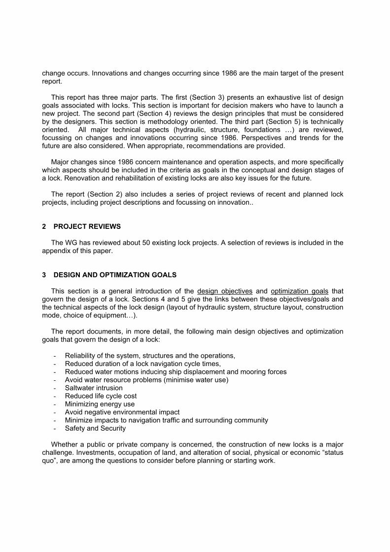
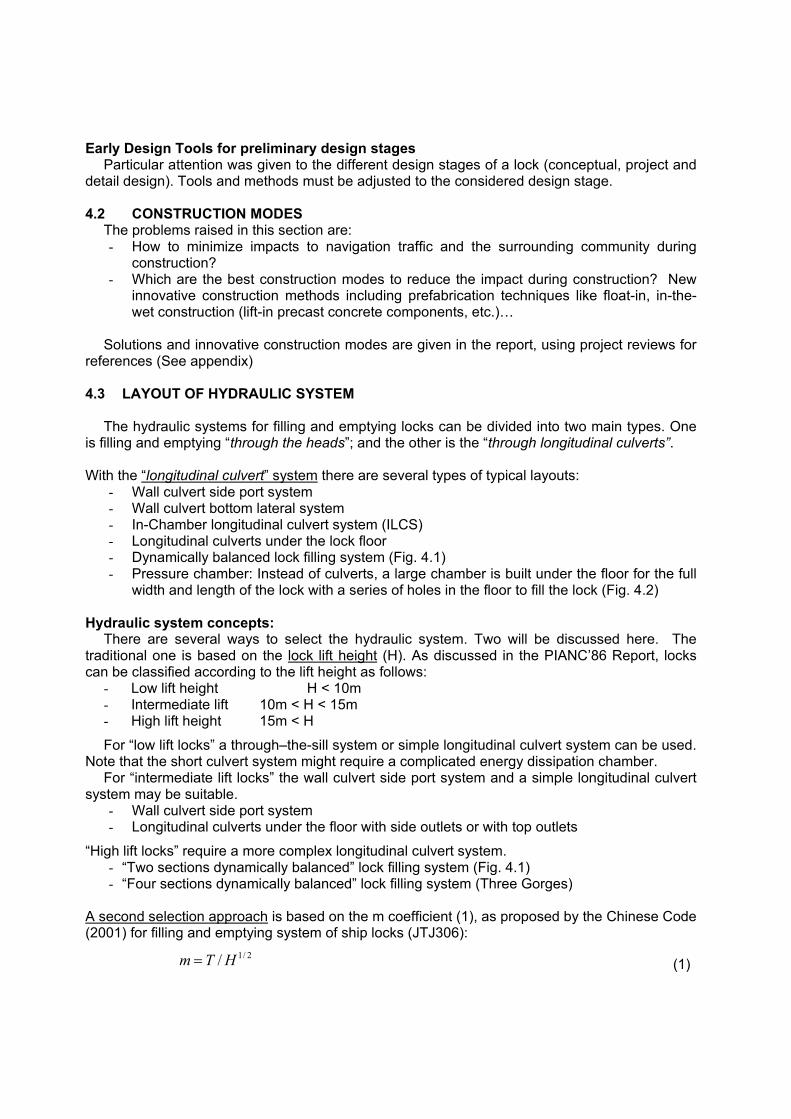
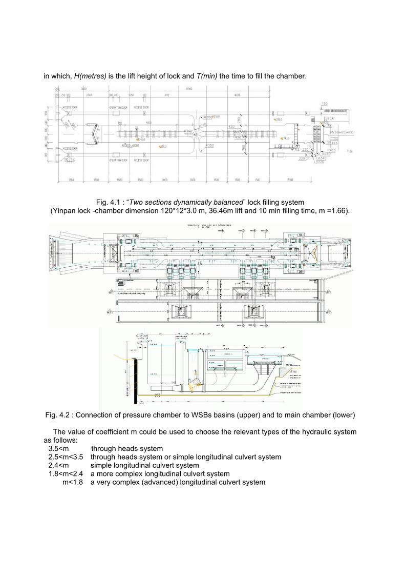
- Wall culvert side port system - Wall culvert bottom lateral system - In-Chamber longitudinal culvert system (ILCS) - Longitudinal culverts under the lock floor - Dynamically balanced lock filling system (Fig. 4.1) - Pressure chamber: Instead of culverts, a large chamber is built under the floor for the full
width and length of the lock with a series of holes in the floor to fill the lock (Fig. 4.2) Hydraulic system concepts:
There are several ways to select the hydraulic system. Two will be discussed here. The traditional one is based on the lock lift height (H). As discussed in the PIANC’86 Report, locks can be classified according to the lift height as follows:
- Low lift height H < 10m - Intermediate lift 10m < H < 15m - High lift height 15m < H
For “low lift locks” a through–the-sill system or simple longitudinal culvert system can be used. Note that the short culvert system might require a complicated energy dissipation chamber.
For “intermediate lift locks” the wall culvert side port system and a simple longitudinal culvert system may be suitable.
- Wall culvert side port system - Longitudinal culverts under the floor with side outlets or with top outlets
“High lift locks” require a more complex longitudinal culvert system. - “Two sections dynamically balanced” lock filling system (Fig. 4.1) - “Four sections dynamically balanced” lock filling system (Three Gorges)
A second selection approach is based on the m coefficient (1), as proposed by the Chinese Code (2001) for filling and emptying system of ship locks (JTJ306):
2/1/HTm = (1)
in which, H(metres) is the lift height of lock and T(min) the time to fill the chamber.
Fig. 4.1 : “Two sections dynamically balanced” lock filling system (Yinpan lock -chamber dimension 120*12*3.0 m, 36.46m lift and 10 min filling time, m =1.66).
Fig. 4.2 : Connection of pressure chamber to WSBs basins (upper) and to main chamber (lower)
The value of coefficient m could be used to choose the relevant types of the hydraulic system as follows:
3.5<m through heads system 2.5<m<3.5 through heads system or simple longitudinal culvert system 2.4<m simple longitudinal culvert system 1.8<m<2.4 a more complex longitudinal culvert system m<1.8 a very complex (advanced) longitudinal culvert system
These values have been defined for a certain set of maximum mooring forces. In practice, complex energy dissipation chambers are only needed when coefficient m<3.5 .
The lock lift height (H) is the main factor in selection of a filling and emptying system (first
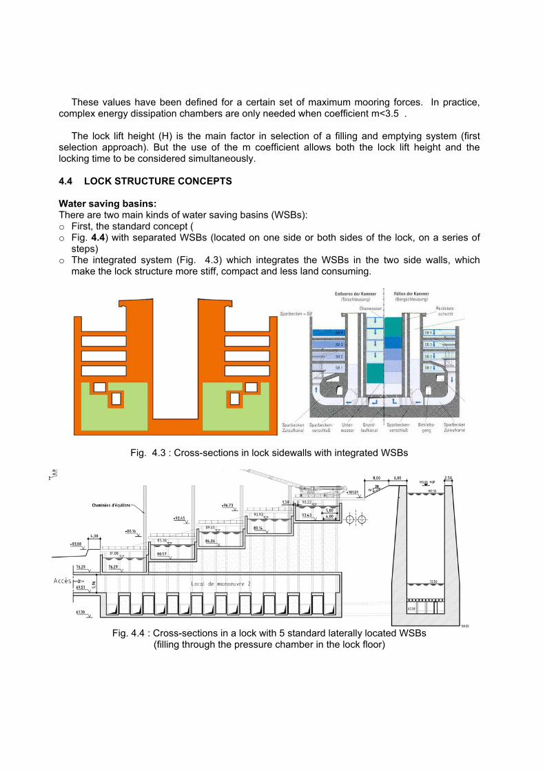
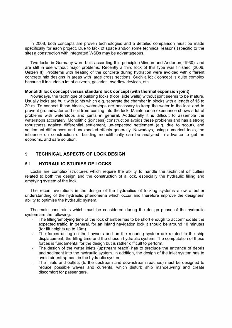
selection approach). But the use of the m coefficient allows both the lock lift height and the locking time to be considered simultaneously. 4.4 LOCK STRUCTURE CONCEPTS Water saving basins: There are two main kinds of water saving basins (WSBs): o First, the standard concept ( o Fig. 4.4) with separated WSBs (located on one side or both sides of the lock, on a series of
steps) o The integrated system (Fig. 4.3) which integrates the WSBs in the two side walls, which
make the lock structure more stiff, compact and less land consuming.
Fig. 4.3 : Cross-sections in lock sidewalls with integrated WSBs
Fig. 4.4 : Cross-sections in a lock with 5 standard laterally located WSBs (filling through the pressure chamber in the lock floor)
In 2008, both concepts are proven technologies and a detailed comparison must be made specifically for each project. Due to lack of space and/or some technical reasons (specific to the site) a construction with integrated WSBs may be advantageous.
Two locks in Germany were built according this principle (Minden and Anderten, 1930), and
are still in use without major problems. Recently a third lock of this type was finished (2006, Uelzen II). Problems with heating of the concrete during hydration were avoided with different concrete mix designs in areas with large cross sections. Such a lock concept is quite complex because it includes a lot of culverts, galleries, overflow devices, etc. Monolith lock concept versus standard lock concept (with thermal expansion joint)
Nowadays, the technique of building locks (floor, side walls) without joint seems to be mature. Usually locks are built with joints which e.g. separate the chamber in blocks with a length of 15 to 20 m. To connect these blocks, waterstops are necessary to keep the water in the lock and to prevent groundwater and soil from coming into the lock. Maintenance experience shows a lot of problems with waterstops and joints in general. Additionally it is difficult to assemble the waterstops accurately. Monolithic (jointless) construction avoids these problems and has a strong robustness against differential settlement, un-expected settlement (e.g. due to scour), and settlement differences and unexpected effects generally. Nowadays, using numerical tools, the influence on construction of building monolithically can be analysed in advance to get an economic and safe solution. 5 TECHNICAL ASPECTS OF LOCK DESIGN
5.1 HYDRAULIC STUDIES OF LOCKS Locks are complex structures which require the ability to handle the technical difficulties
related to both the design and the construction of a lock, especially the hydraulic filling and emptying system of the lock.
The recent evolutions in the design of the hydraulics of locking systems allow a better understanding of the hydraulic phenomena which occur and therefore improve the designers’ ability to optimise the hydraulic system.
The main constraints which must be considered during the design phase of the hydraulic system are the following:
- The filling/emptying time of the lock chamber has to be short enough to accommodate the expected traffic. In general, for an inland navigation lock it should be around 10 minutes (for lift heights up to 10m).
- The forces acting on the hawsers and on the mooring system are related to the ship displacement, the filling time and the chosen hydraulic system. The computation of these forces is fundamental for the design but is rather difficult to perform.
- The design of the water inlets (upstream reach) has to preclude the entrance of debris and sediment into the hydraulic system. In addition, the design of the inlet system has to avoid air entrapment in the hydraulic system
- The inlets and outlets (to the upstream and downstream reaches) must be designed to reduce possible waves and currents, which disturb ship manoeuvring and create discomfort for passengers.
- The speed of the flow inside the galleries and culverts must be limited to avoid significant head losses and cavitation, particularly in bends with a small radius. In general, average flow speeds above 7-10 m/s should be avoided.
Obviously, the different elements mentioned above are inter-independent and interact with
each other. For instance, if we speed up the opening of the valves, the locking duration will be shorter but we will have problems with other parameters (higher mooring forces, higher waves in the lock chamber and in the downstream side of the lock, more debris flow admitted at the inlets of the hydraulic system, higher risk of cavitation …). Interrelations between analytical, experimental and numerical analysis
Twenty years ago, the design of hydraulic locking system was mainly performed with the support of physical models (usually scale models).
Nowadays numerical models allow, with reasonable accuracy, preliminary design and
evaluation of alternatives of the hydraulic system. The physical model comes later to perform a final validation of the design. This approach reduces the total design period and cost.
The next section focuses on integrated approaches between the analytical/numerical models and physical modelling. This is an area that has significantly changed since 1986.
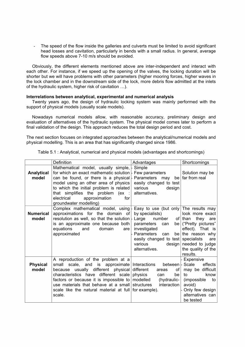
Table 5.1 : Analytical, numerical and physical models (advantages and shortcomings) Definition Advantages Shortcomings
Analytical
model
Mathematical model, usually simple, for which an exact mathematic solution can be found, or there is a physical model using an other area of physics to which the initial problem is related that simplifies the problem (ex : electrical approximation for groundwater modelling)
- Simple - Few parameters - Parameters may be
easily changed to test various design alternatives.
Solution may be far from real
Numerical
model
Complex mathematical model, using approximations for the domain of resolution as well, so that the solution is an approximate one because both equations and domain are approximated
- Easy to use (but only by specialists)
- Large number of parameters can be investigated
- Parameters can be easily changed to test various design alternatives.
The results may look more exact than they are (“Pretty pictures” effect). That is the reason why specialists are needed to judge the quality of the results.
Physical
model
A reproduction of the problem at a small scale, and is approximate because usually different physical characteristics have different scale factors or because it is impossible to use materials that behave at a small scale like the natural material at full scale.
Interactions between different areas of physics can be modelled (hydraulic-structures interaction for example).
- Expensive - Scale effects
may be difficult to know (impossible to avoid)
- Only few design alternatives can be tested

The contribution of analytical, numerical and physical modelling In recent years, in view of the rapid development of computer technology with higher
computing power and ever lower cost, numerical models have been applied in some areas of technical hydromechanics with great success. The question has to be raised whether numerical models can, in the future, take the place of the physical model, and what are the advantages to be gained.
Whether for hydraulics inside or in the vicinity of the lock, for structural analysis (concrete,
metallic structures, geo-mechanics), or for the economics (relevance of double locks, maintenance systems…), numerical models seem to be a viable tool.
Research in the area of numerical models is prolific, but still demonstrates the necessity for
improvements. Table 5.1 presents the distinctions between analytical, numerical and physical models, and
their advantages and shortcomings.
Table 5.2 : Comparison between physical and numerical models
STEP PHYSICAL MODEL NUMERICAL MODEL 1 Definition of the problem Identification of the essential acting forces 2 Formulation of similarity requirements Formulation of sets of equations 3 Formulation of boundary conditions 4 Construction of a model Development of a numerical solution scheme 5 Calibration of the model Variation of roughness or like Variation of coefficients 6 Measurements and solution Calculation and solution 7 Optimization of the solution according to problem formulation Model geometry variations Variation of input data 8 Transfer of results from model to prototype and examination by field measurements
A comparison between physical and numerical models (Table 5.2) shows at first glance that
both of models have much in common. Each must be preceded by a conceptual phase, in which the physical relationships to be simulated by the model have to be identified. Calibration is a key element of either approach, and frequently requires data from previous projects if solutions are not to be pre-judged. Limitations of physical and numerical models are detailed in the full report of the WG29
5.2 GATES AND VALVES Mechanical parts: seals, bearings, hydraulic cylinders, operating equipments
In the last 20 years the mechanical parts of locks (mitre gate hinges, rails, bearings...) have been improved: more efficient materials (high tensile steel, better anti-friction characteristics...), drives improved, etc.
In recent designs the emphasis is to design mechanical parts to make maintenance easier
and improve reliability.

Key functions of the main mechanical parts are given in Table 5.3. Sealing
Gate seals are required to prevent loss of water. Seals used in locks are generally made of rubber or wood (Azobe for instance).
The selection of seals and the design of their installation are important. The required
properties for rubber seals include suppleness, hardness, ultraviolet resistance and abrasion resistance. The seal’s supports must be easily accessible and removable. In addition, seals should be resistant to or protected from floating debris and ship impacts. Maintenance
Maintenance is an important consideration in the design of the mechanical parts. Designers should minimize maintenance and repair costs and duration by design improvements. That is why we must take the questions of accessibility, removal and installation into consideration.
It is very important to be able to assess the current wear (for example fretting wear) without
dismantling the entire system.
Table 5.3 : Main Mechanical Parts
FUNCTIONS ELEMENTS Gate operation and power supply (transmission of a force to the mobile structure)
- actuators - drives (cylinders, electro-mechanical drives...) - motors - chain, cables
Guiding (rotation, translation) - rails - wheels and rollers - pivot , articulation
Bearing and contacts (sliding, rolling or static), transmission of forces to the foundation of the lock
- rails - wheels and rollers - pivot , articulation
Sealing - seals Maintenance - accessibility
- capacity to remove and change elements 6 CONCLUSION
INCOM WG 29 expects to finalize this work before the end of 2008, so the report will be available in 2009. Feedback and comments on this paper are welcome and will be considered in the final version 7 REFERENCES PIANC, 1986, “Final Report of the International Commission for the Study of Locks”, PIANC, Brussels, 460pp.