Embed Size (px)
Citation preview

Innovation Project: Interlayers on Highway 36 near
Chester, California
Highway 36 One Year After
Report Number: CP2 – 2008 - 101
March 12, 2008
California Pavement Preservation Center 203 Langdon Hall
California State University Chico, California 98929-0930
(530) 898-6032

i
PROJECT SUMMARY PAGE Technical Report: CP2-2008 - 101
Title: Innovation Project: Interlayers on Highway 36 near Chester, California Authors: Lance Brown, P.E., and M. Stroup-Gardiner Prepared for: CALTRANS California Department of Transportation
Client Reference No.: Project 02-PLU-036
Prepared by: California Pavement Preservation Center 203Langdon Hall California State University Chico, California 95927-0930
Date: January 24, 2008
Abstract: In Plumas County California, Caltrans placed 4 interlayer test sections. The test sections were overlaid with 30mm rubberized asphalt concrete. The interlayer systems used were: 1) fiberglass polyester paving mat; (Paving mat), 2) polymer modified emulsion (PME) chip seal;PMCRS-2h 3) asphalt rubber (AR) chip seal and 4) modified binder (MB) chip seal. The purpose of these test sections is to determine the effectiveness of an interlayer system to enhance performance of a surface treatment and reduce field maintenance of pavements that have exceeded the design life. Approximately ½ mile of the non-standard MB chip seal did not receive an overlay to allow an evaluation of this new hot applied chip seal. After 1 year of weather and traffic, all four of the test sections are performing well. The only distresses seen in the surface is a limited number of transverse cracks and slight oxidation of the pavement. The MB chip seal, with no hot mix asphalt layer, is showing a slightly higher severity of transverse cracks. It is not clear if the transverse cracks are a function of the RAC-G binder properties or reflection cracks from the distresses in the old pavement. Keywords: Interlayers, Reflective Cracking, Chip Seals, Asphalt Rubber, Paving Mat

ii
ACKNOWLEDGEMENTS
The author is grateful to the assistance provided by Dr Tom Ferrera, CP2 Center, of the California Pavement Preservation Center. The authors would also like to thank Scott Dmytrow,
Mike Fain and Karl Meyers from Telfer Oil, Inc., Caltrans Matt Gowan (Project Engineer), Karlie Smith (Assistant Project Engineer) and Fred Chaffin (Resident Engineer) for their
valuable contributions on this project.
DISCLAIMER
The contents of this report reflect the views of the authors who are responsible for the facts and accuracy of the data presented herein. The contents do no necessarily reflect the official views
or polices of the State of California or the Federal Highway Administration

iii
TABLE OF CONTENTS INTRODUCTION ................................................................................................................. 1 SECTION 1 – Paving Mat with 30 mm RAC-G ................................................................. 10 SECTION 2 - POLYMER MODIFIED EMULSION (PME) INTERLAYER ................... 12 SECTION 3 – ASPHALT RUBBER (AR) CHIP SEAL INTERLAYER .......................... 14
Materials ...........................................................................................................................14 AR Interlayer Test Sections ..............................................................................................16
SECTION 4 MODIFIED BINDER (MB) CHIP SEAL INTERLAYER ............................ 17 RAC-G MIX ........................................................................................................................ 18 SHOULDERS ...................................................................................................................... 19 SUMMARY ......................................................................................................................... 19 LESSONS LEARNED......................................................................................................... 19 REFERENCES .................................................................................................................... 20
APPENDIX A – Innovation Pre-Proposal, Proposal, and Final Report Format APPENDIX B – Fiberglass/Polyester Paving Mat APPENDIX C – Asphalt Rubber Seal Coat NSSP APPENDIX D – Modified Binder Seal Coat APPENDIX – E – Polymer Modified Emulsion Seal Coat
TABLE OF TABLES Table 1. Layout and Information about Test Sections .................................................................... 2 Table 3. 2005 Truck Traffic on Highway 36 at Plumas/Lassen County Line ................................ 6 Table 2. Location and layers present in the existing HMA pavement. ........................................... 9 Table 4. Physical Properties of fiberglass polyester paving mat .................................................. 11 Table 5. Properties of emulsion residue after evaporation. .......................................................... 12 Table 6. Caltrans screening requirements ..................................................................................... 13 Table 7. Upper PG temperature requirements for unmodified ..................................................... 14 Table 8. Requirements for asphalt modifiers used in asphalt rubber blends. ............................... 14 Table 9. Material requirements for scrap tire and high natural rubber CRM. .............................. 15 Table 10.Required blended asphalt rubber properties. ................................................................. 15 Table 11. Caltrans screening requirements for asphalt rubber chip seals (hot applied). .............. 16 Table 12. Caltrans RAC-G requirements for aggregates .............................................................. 18

iv
TABLE OF FIGURES Figure 1. Project Location near Chester, California. ...................................................................... 2 Figure 2. Typical pre-construction roadway condition. .................................................................. 3 Figure 3. Typical pavement cross sections for Highway 39 near Chester, California interlayer projects. ........................................................................................................................................... 4 Figure 4. Pavement layers for innovation project 02-PLU-036. ..................................................... 5 Figure 5. Hourly traffic distribution for PM 14 through PM18.5 (2006). ..................................... 6 Figure 6. Existing ride quality before placing the surface treatments. .......................................... 7 Figure 7. Existing rut depths before placing the surface treatments. ............................................. 7 Figure 8. Existing pavement transverse cracking before placing the surface treatments. ............. 8 Figure 9. Existing pavement patching before placing the surface treatments. ............................... 8 Figure 10. Existing pavement deflection data before placing surface treatments. ........................ 9 Figure 13. Section 2 before and after leveling course. ................................................................. 12 Figure 14. Typical condition of PME interlayer before, during, and 1 year after construction. .. 13 Figure 15. Typical structural section in Section 3 (AR chip interlayer). ..................................... 16 Figure 16. AR chip seal interlayer after placement and 1 year after construction. ...................... 17 Figure 17. Typical digout repairs prior to leveling course and typical structural thickness. ....... 17 Figure 18. MB chip seal interlayer immediately and 1 year after construction. .......................... 18

INTRODUCTION Pavement interlayers are materials or combinations of materials that can be placed within a pavement system during new construction, rehabilitation or preservation in conjunction with an overlay or surface treatment to extend pavement service life (MTAG Chapt. 12 draft 2008). In addition, some types of interlayer systems allow for the reduction of an overlay-only thickness due to the strain and/or stress relief. Past experience in California with asphalt rubber chip seals and non-woven polyester interlayers over crack and seat or asphalt overlays has been positive. However, Caltrans has limited experience with other interlayer products combined with thin, non-structural surface mix overlays. One of the few interlayer projects constructed and monitored over 13 years was sponsored by the California Integrated Waste Management Board (CIWMB) and constructed at the Esparto site in 1992. After 13 years, the flexible interlayer and thin overlay sections have performed well. As noted in the conclusions of a report prepared in 2004 all test sections at the Esparto Site exceeded the expected design life of 5 to10 years.
In California, state pavement preservation and maintenance overlay projects are defined as have a thickness of less than 30 mm. Capital preventive maintenance (CaP-M) projects are defined as overlays of no more than 50 mm. Overlays thicker than 50 mm are considered rehabilitation projects. When a project is identified as being a preservation project, the source of funding will therefore dictate the thickness of overlay that can be placed over the interlayer. Some interlayer systems require a minimum of 37.5 mm overlay thickness so they may be eliminated from consideration for preservation or maintenance projects.
The innovative project constructed by Caltrans in Plumas County was constructed under the preservation program funding, so the overlay was limited to 30 mm. The purpose of this innovative project is to compare four interlayer systems (3 chip seals and one paving mat) to the control (untreated) section. This report describes the site selection, construction, and one year after construction performance of these test sections. Non-standard special provisions, recommended manufacturer paving mat suppliers, and the innovation project submission documents are included in appendices.
2
PROJECT DESCRIPTION The project was constructed in Plumas County, State Route (SR) 36 at postmile 14 to 18.42 (Figure 1). State Route 36 is a 2 lane convention highway with an average daily traffic of from 2200 to 5000 vehicles per day. The site selected for the test was a location in a poor state of repair (Figure 2), and low on the Districts priority for rehabilitation as an ultimate form of repair. The damage was beyond maintenance therefore a non-conventional means of adding service life was utilized in the form of a “2-layer” system as known as an interlayer. Table 1 identifies the type of interlayer that was placed in each section of the project.
Figure 1. Project Location near Chester, California.
Table 1. Layout and Information about Test Sections (Specifications in Appedices B, C, and D)
Section Number Post Mile Interlayer
Used Surfacing
1 14.0 - 15.0 Fiberglass/Polyester Paving Mat 30 mm RAC-G
Transition 15.0 - 15.1 None 30 mm RAC-G 2 15.1 - 16.1 PME Chip Seal 30 mm RAC-G
Transition 16.1 - 16.2 None 30 mm RAC-G
3 16.2 - 17.2 AR Chip Seal 30 mm RAC-G
Transition 17.2 - 17.3 None 30 mm RAC-G
4 17.3-18.0 MB Chip Coat 30 mm RAC-G
Seal only 18.0 - 18.42 None MB Chip Seal

3
Figure 2. Typical pre-construction roadway condition.
Typical existing pavement distresses on Highway 36, east of Chester, CA
PM 14.0 to 18.42

4
Figure 3 shows the typical pavement cross section of the pavement structure. Figure 4 details the interlayer test section materials from the bottom (subgrade) to the surface course (30 mm of RAC-G). The project site was thoroughly reviewed for severity and cross section to determine the most appropriate location for each interlayer material. Photos of the condition of the roadway and core for thickness determination for each interlayer test section are shown in the following sections.
Figure 3. Typical pavement cross sections for Highway 39 near Chester, California interlayer projects.

5
-PM
14.
00
-PM
14.
91
-PM
15.
19
-PM
16.
00
-PM
16.
29
-PM
17.
11
-PM
17.
39
-PM
17.
91
-PM
18.
42
Project Limits:
30 mm RAC
Type G
30 mm RAC
Type G 30 mm RAC
Type G 30 mm RAC
Type G
MB Chip Seal Only
Paving Mat
PME Chip
Seal AR Chip Seal
MB Chip Seal
3/16- leveling course (as required 0-38 mm)
Existing (Failed) Pavement (Digouts as Required)
AC Basic Mix Design:
Type Binder PG 64-10 Type G (Paramount) Type Aggregate gap-graded 3/4-inch
% Oil 7.70% % Rubber 18 - 20%
Compaction 96 - 97%
Lime Ratio 1.20%
Seal Coats: Type Binder PMCRS-2H Modified Binder
Application Rate 0.33 gal/yd2 0.62 gal/yd2 0.39 gal/yd2
Source of Binder
VSS Emultech
Type Aggregate 1/2-inch 1/2-inch 3/8-inch, hot applied App Rate of
Aggregate 19.3 - 22.6
lb/yd2 30 lb/yd2 28 lb/yd2 Source of
Aggregate Tiechert/Perkins ??
Lime Ratio Paving Mat: 100% polypropylene
staple fiber mat material, needle-punched, thermally bounded on one-side, 140 g/m2, 0.45 KN grab tensile strength, 50% elongation at break, 900 g/m2 asphalt retention.
(3/16 minus) Leveling Course:
Type Binder PG 64-10 Type A Type Aggregate 3/16-inch
% Oil 7.70% Placement
Method Placed with Shuttle Buggy and vibrating screed paver. Tracked-In with pneumatic tires. Lime Ratio 1.20%
Existing AC
Figure 4. Pavement layers for innovation project 02-PLU-036.

6
Traffic information was also provided by District 2. The traffic levels reported for 2006 on the Caltrans Website were at 3,050 for the peak month Average Daily Traffic (ADT) and at 2,300 Average Annual Daily Traffic (AADT). Fourteen percent of the traffic was reported to be trucks for the 2005 data on the Caltrans Website; the AADT was 2,300 for 2005. The distribution of truck traffic in the AADT is shown in Table 3. Hourly traffic counts for the section are shown in Figure 10.
Table 2. 2005 Truck Traffic on Highway 36 at Plumas/Lassen County Line
Number of Axels
Number of Trucks
Percentage of Trucks Percent of AADT
2 26 8 1 3 77 24 3 4 23 7 1
5+ 196 61 9
All Trucks 322 100 14
020406080
100120140160180
0:00 3:00 6:00 9:00 12:00 15:00 18:00 21:00 0:00
Hourly Traffic Count
Tim
e, h
East Bound West Bound
Figure 5. Hourly traffic distribution for PM 14 through PM18.5 (2006).
Information was collected prior to construction by District 2 for ride quality, rut
depths, alligator cracking, transverse cracking, and patching. Figure 5 shows a ride quality expressed at the International Roughness Index (IRI) was typically less than 100 in/mile for the first one mile of the project. Figure 6 shows the rutting was also very low (less than 5mm), in the first mile of the project while the remainder of the roadway had rut depths varying widely from 5 to 25 mm. Conversations with industry on the history of this portion of the roadway yielded the information that a leveling course had been placed a couple of years earlier. While the leveling course did not significantly reduce the cracking noted in this section (Figures 7 and 8), it does provide an explanation for the smoother ride and lack of rutting

7
0
50
100
150
200
250
300
350
400
14 15 16 17 18 19
Posted Miles
IRI,
in/m
i
IRI, EB IRI, WB
Paving Mat
+ 30 mm RAC-G
PME Chip + 30 mm RAC-G
AR Chip + 30 mm RAC-G
MB Chip + 30 mm RAC-G
MB Chip
Figure 6. Existing ride quality before placing the surface treatments.
0
5
10
15
20
25
30
14 15 16 17 18 19
Posted Miles
Rut
Dep
th, m
m
Rutting, EB Rutting, WB
Paving Mat + 30 mm RAC-
G
PME Chip + 30 mm RAC-G
AR Chip + 30 mm RAC-G
MB Chip + 30 mm RAC-G
MB Chip
Figure 7. Existing rut depths before placing the surface treatments.
The cracking recorded for the pavement condition survey showed the most
common distress was the transverse cracking (Figure 7). While this figure shows lower transverse cracking between PM 16.5 and 18.5, this is only because the alligator cracking and patching of the roadway in this area was so extensive that the transverse cracking could not be singled out. Figure 8 shows about half of the project had a fair amount of patching (about PM16.5 to PM18.5). This is also the portion of the road that had most of the dig out repairs prior to placing the interlayers. The average length the digouts was 20m and the total tonnage equaled was 370 tonnes. This amount was insignificant to the overall distress. A leveling course was placed on the remaining four miles of the project prior to the placement of the chip seal interlayers and chip seal only sections.

8
0
10
20
30
40
50
60
70
14 15 16 17 18 19
Posted Miles
Exte
nt o
f Tra
nsve
rse
Cra
ckin
g
Transverse Cracking, EB Transverse Cracking, WB
Paving Mat + 30 mm RAC-G
PME Chip + 30 mm RAC-G
AR Chip + 30 mm RAC-G
MB Chip + 30 mm RAC-G
MB Chip
Figure 8. Existing pavement transverse cracking before placing the surface treatments.
0
50
100
150
200
250
14 15 16 17 18 19
Posted Miles
Patc
hing
, Ft.
Patching, EB Patching, WB
Paving Mat + 30 mm RAC-
G
PME Chip + 30 mm RAC-G
AR Chip + 30 mm RAC-G
MAB Chip + 30 mm RAC-G
MAB Chip
Figure 9. Existing pavement patching before placing the surface treatments.
The falling weight deflectometer (FWD) testing was conducted pre-construction to provide a baseline for post-construction stiffness measurement comparisons. This post construction testing is expected to provide information on the strain and/or stress dissipation characteristics of the interlayers. Table 2 indicates the location, type of structural layer, the total thickness of the section, the type of base material, and remarks from the testing staff. Figure 9 shows the deflection varied between 0.010 and 0.030 mils; generally similar deflections were obtained when comparing the East and West

9
bound lanes. That is, if the deflection was high in the East Bound lane, it was also likely high in the West bound lane. Table 3. Location and layers present in the existing HMA pavement.
Test Section
Core Hole Location (PM, Lane No.,
Direction)
Layer 2 (Struct. Sect.)
Total Core
Thickness
Layer 5(Base Matrl)
Remarks
Paving Mat +
RAC-G
14.560, L1, EB 0.40 DGAC 0.40 AB INTACT
14.48, L1, WB 0.50 DGAC 0.50 AB DELAM @ 0.32' FROM TOP
PME Chip + RAC-G
15.210, L1, WB 0.48 DGAC 0.48 AB INTACT 15.250, L1, EB 0.50 DGAC 0.50 AB DELAM @ 0.27' FROM TOP 15.720, L1, EB 0.44 DGAC 0.44 OG INTACT (HOLE WAS MEASURED)
AR Chip + RAC-G
16.56, L1, EB 0.75 DGAC 0.75 AB INTACT 16.770, L1, WB 0.73 DGAC 0.73 AB DELAM @ 0.09' FROM TOP
MB Chip + RAC-G 17.227, L1, EB 0.50 DGAC 0.50 AB INTACT
MB Chip Only 18.20, L1, WB 0.52 DGAC 0.52 OG INTACT
DGAC: Dense graded asphalt concrete AB: Aggregate Base OG: Original Ground EB: East Bound WB: West Bound
0.000
0.005
0.010
0.015
0.020
0.025
0.030
0.035
14 15 16 17 18 19
Posted Miles
Def
lect
ion,
mils
Deflection, EB Deflection WB
PM locations estimated from deflection file notes
Paving Mat + 30 mm RAC-G
PME Chip + 30 mm RAC-G
AR Chip + 30 mm RAC-G
MB Chip + 30 mm RAC-G
MB Chip
Figure 10. Existing pavement deflection data before placing surface treatments.
10
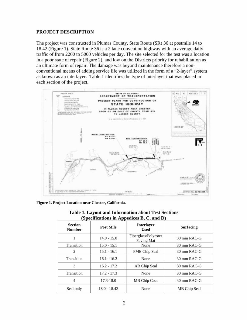
SECTION 1 – Paving Mat with 30 mm RAC-G Figure 11 shows the original condition of this specific section prior to construction and the structural thickness of the pavement. There is about 110 mm of HMA with four visible layers in the core. The existing leveling course on this section of roadway is easy to see in this figure.
02-1C8201 PLU-36 13.9/18.4
EB 36 LANE 1 PM 14.00
02-1C8201 PLU-36 13.9/18.4
EB 36 LANE 1 PM 14.56
02-1C8201 PLU-36 13.9/18.4
TEST 5 WB 36 LANE 1 PM 14.480
The paving mat was placed on September 1 and 2, 2006. The surface was cleaned prior to spraying the PG64-10 hot applied binder, which was immediately followed by the placement of the paving mat fiberglass paving mat. The paving mat was overlaid with 30 mm of gap graded rubberized asphalt concrete (RAC-G) mix. Documentation and background information for the placement of generic fiberglass paving mats can be found in Appendices B and C. It should be noted that the 30 mm of hot mix over the paving mat is less than the manufacturer’s recommended thickness of 3 times the maximum aggregate size for the covering lift thickness. The RAC-G used a ½ inch maximum size aggregate so the manufacturer recommended cover thickness would have been 1.5 inches (38 mm).
The material requirements for fiberglass polyester paving mats are given in Section 88 “Engineering Mats” of the Standard Specifications and the special provisions in the Innovative Materials contract 02-1C8204. These requirements state that the mat shall be non-woven, heat treated on at least one side, manufactured with fiberglass combined with polyester, polypropylene or polypropylene-nylon material with the properties shown in Table 4.
Figure 11. Section 1 Existing pavement surface and structural thickness.

11
Table 4. Physical Properties of fiberglass polyester paving mat Property Test Method Units Minimum Average
Roll Value (MARV) Mass per unit area ASTM D5261 g/m2 (oz/yd2) 125 (3.69) Tensile Strength, MD ASTM D5035 N/50 mm (lb/2 in) 200 (45) Tensile Strength, CD ASTM D5035 N/50 mm (lb/2 in) 200 (45) Elongation at maximum load, MD ASTM D5035 % <5 Elongation at maximum load, CD ASTM D5035 % <5 Melting Point ASTM D276 oC (oF) >250 (>446)
Section 1 with the Paving mat interlayer exhibited some moderate severity reflective transverse cracks on the shoulder; however the plans do not reflect the use of any type of inner layers on the shoulders. In the traveled lanes the wheel path showed very slight wear, most likely due to tire chains. There was some very minor large aggregate raveling on the surface of the RAC-G overlay. Figure 12 shows the condition of this section one year after placement.
Existing Condition
Paving Mat + 30 mm RAC-G After 1 Year
Highway 36 EastOf Chester
PM 14.0 to 15.0
Figure 12. Section 1 with Paving Mat Interlayer before mat was placed and 1 year after construction.
12
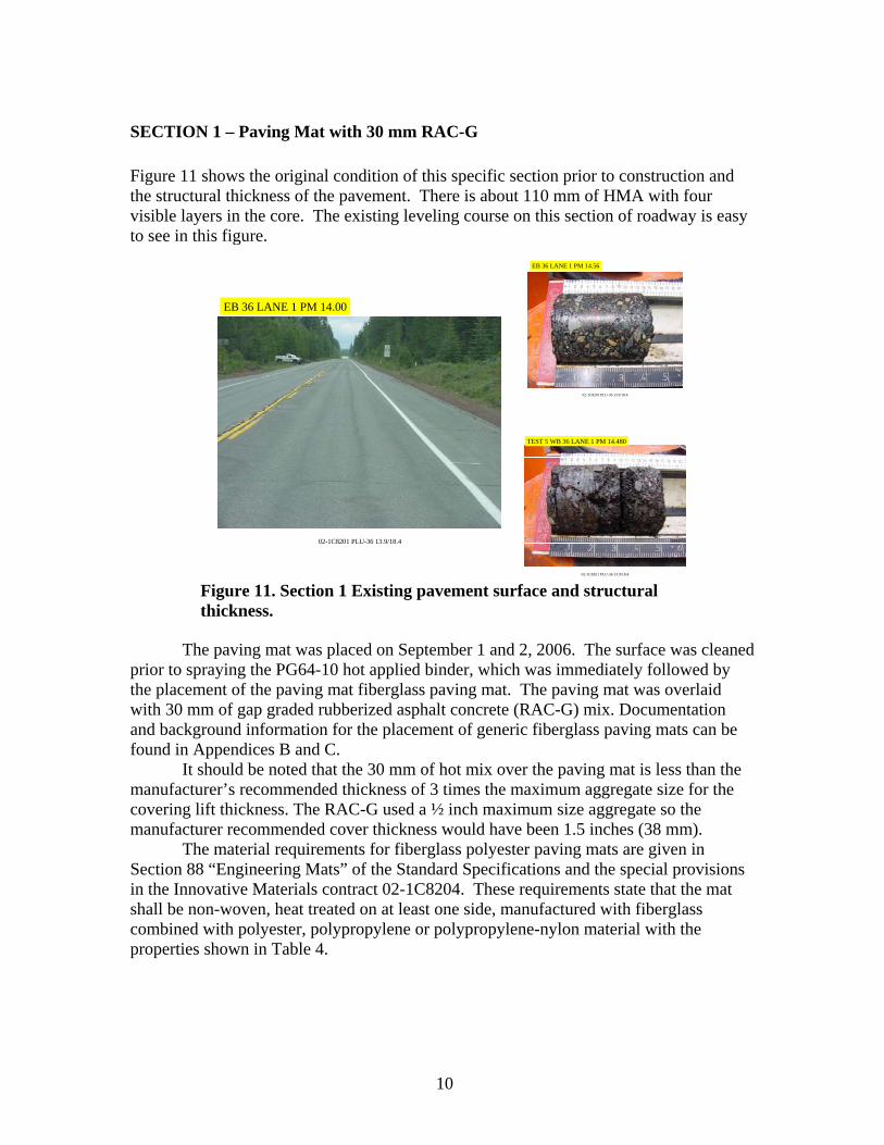
SECTION 2 - POLYMER MODIFIED EMULSION (PME) INTERLAYER Figure 13 shows the condition of this section of roadway prior to the placement of the PME interlayer. In order to place seal coats on pavement in such poor condition, a stiff PG 70-10, ¼” minus (4.75 mm minus) hot mix asphalt (HMA) leveling course was placed first.
02-1C8201 PLU-36 13.9/18.4
EB 36 LANE 1 PM 15.50 SECTION AFTER LEVELING COURSE
Figure 13. Section 2 before and after leveling course. The authors want to recognize that the contractor elected to use a Materials
Transfer Device (MTD) for both the leveling course and the placement of the rubberized asphalt concrete (RAC-G). This level of commitment by the contractor to the placement of a uniform thin surface resulted in a high quality surface on which to place the seal coats (photos, Appendix A). While MTD’s are not typically used for interlayers, this should be considered an important part of any future interlayer placement.
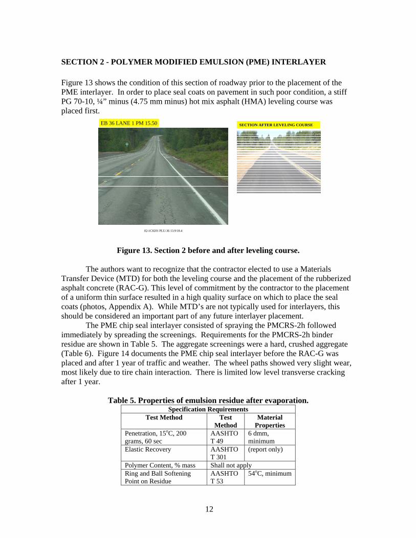
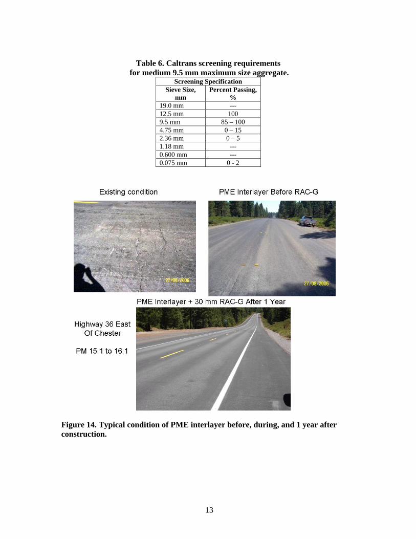
The PME chip seal interlayer consisted of spraying the PMCRS-2h followed immediately by spreading the screenings. Requirements for the PMCRS-2h binder residue are shown in Table 5. The aggregate screenings were a hard, crushed aggregate (Table 6). Figure 14 documents the PME chip seal interlayer before the RAC-G was placed and after 1 year of traffic and weather. The wheel paths showed very slight wear, most likely due to tire chain interaction. There is limited low level transverse cracking after 1 year.
Table 5. Properties of emulsion residue after evaporation. Specification Requirements
Test Method Test Method
Material Properties
Penetration, 15oC, 200 grams, 60 sec
AASHTO T 49
6 dmm, minimum
Elastic Recovery AASHTO T 301
(report only)
Polymer Content, % mass Shall not apply Ring and Ball Softening Point on Residue
AASHTO T 53
54oC, minimum
13
Table 6. Caltrans screening requirements
for medium 9.5 mm maximum size aggregate. Screening Specification
Sieve Size, mm
Percent Passing, %
19.0 mm --- 12.5 mm 100 9.5 mm 85 – 100 4.75 mm 0 – 15 2.36 mm 0 – 5 1.18 mm --- 0.600 mm --- 0.075 mm 0 - 2
Figure 14. Typical condition of PME interlayer before, during, and 1 year after construction.

14
SECTION 3 – ASPHALT RUBBER (AR) CHIP SEAL INTERLAYER Materials Requirements for Asphalt Rubber Seal Coat are defined in Section 37-1. A Certificate of Compliance as defined by the Certification Program for Suppliers of Asphalt (Caltrans 2006) is required for suppliers of asphalt rubber product. The contractor is also required to submit a Certificate of Compliance for each truck load of crumb rubber modifier (CRM) used to produce the asphalt rubber binder.
The asphalt rubber binder is a blend of paving grade asphalt cement, asphalt modifier, and crumb rubber modifier (CRM) from both scrap passenger car and high natural rubber content (i.e., truck tires). Paving grade asphalt cement is specified as non-polymer modified performance graded (PG) asphalt that meets the requirements shown in Table 7. The PG asphalts which overlay these upper ranges may be approved by the Project Engineer.
Table 7. Upper PG temperature requirements for unmodified
paving grade asphalt cement. Caltrans Range Average 7 Day Maximum Pavement
Design Temperature Minimum Pavement Design Temperature
Range A Below 62oC Not Specified Range B Between 62 and 68oC (exclusive)
Range C Greater than 68oC
The asphalt modifier is a resinous, high flash point aromatic hydrocarbon compound added to the paving grade asphalt at between 2.0 and 6.0% by mass of paving grade asphalt. The actual percent for a particular blend should be made based on the recommendation of the asphalt-rubber binder supplier. The physical property requirements for the asphalt modifier are shown in Table 8.
Table 8. Requirements for asphalt modifiers used in asphalt rubber blends. Test Parameter ASTM
Designation for Test Method
Specification Requirement
Viscosity, m2/s (10-10) at 100oC D445 19 – 36 (+/- 3) Flash Point, Cleveland Open Cup, oC D92 207 minimum Molecular Analysis Asphaltenes, % by mass D2007 0.1 maximum Aromatics, % of mass D2007 35 minimum
The CRM specification requires steel and fiber separation is accomplished using a
cryogenic process so that no more than 0.01% wire and no more than 0.05% mat, both by mass of CRM.
After cryogenic separation, the CRM is ground at ambient temperature to achieve the gradations shown in Table 9. The maximum length of any single CRM particle is limited to 4.75 mm. The CRM needs to be dry so that the material will flow freely and not foam when added to the heated paving grade asphalt. A maximum of 3% of calcium

15
carbonate or talc by mass of CRM can be added to help the flow characteristics of the CRM.
Table 9. Material requirements for scrap tire and high natural rubber CRM.
Rubber Type Sieve Size, mm Specification Requirements
Gradation Requirements
Operating Range
Contract Compliance
Scrap Tire CRM
2.36 100 100 100 2.00 98 - 100 95 - 100 90 - 100 1.18 45 -75 35 – 85 32 – 88 0.60 2 – 20 2 – 25 1 – 30 0.30 0 – 6 0 – 10 0 - 15 0.15 0 - 2 0 - 5 0 – 10
0.075 0 0 – 2 0 - 5 ASTM D297 Minimum Maximum Acetone Extract 6.0 16.0 Ash Content --- 8.0 Carbon Black Content 28.0 38.0 Rubber Hydrocarbon 42.0 65.0 Natural Rubber Content 22.0 39.0
High Natural Rubber CRM
Sieve Size, mm Specification Requirements
Gradation Requirements
Operating Range
Contract Compliance
2.36 --- --- --- 2.00 100 100 100 1.18 95 – 100 92 – 100 85 – 100 0.60 35 – 85 25 - 95 20 – 98 0.30 10 – 30 6- 35 2 – 40 0.15 0 – 4 0 – 7 0 – 10
0.075 0 - 1 0 – 3 0 - 5 ASTM D297 Minimum Maximum Acetone Extract 4.0 16.0 Rubber Hydrocarbon 50.0 --- Natural Rubber Content 40.0 48.0
The blended asphalt rubber binder is 79% (+/- 1%) of combined paving grade
asphalt cement and asphalt modifier and 21% (+/- 1%) CRM, where the CRM is made up from 76% (+/-2%) scrap tire rubber and 24% (+/-2%) high natural rubber. The CRM is added the paving grade binder at a temperature of between 190 and 226oC, reacted for at least 45 minutes at temperatures between 190 and 218oC but not more than 4 hours. The asphalt rubber binder will have properties shown in Table 10.
Table 10.Required blended asphalt rubber properties.
Test Parameter ASTM Test Method
Blended Asphalt Rubber Binder Minimum Maximum Minimum Maximum
Cone Penetration, 25oC, dmm D217 25 70 25 60 Resilience, 25oC, % Rebound D3407 18 --- 18 --- Field Softening Point, oC D36 52 74 55 88 Viscosity, 190oC, Pa-s(x 10-3) Hand Held Haake 1,500 2,500 1,500 2,500 Table 11 shows the two different gradations which can be used for AR chip seals. The requirements for the chips are also given in this table.

16
Table 11. Caltrans screening requirements for asphalt rubber chip seals (hot
applied). 12.5 mm
Medium-Coarse 12.5 Coarse
Sieve Size, mm Percent Passing, % 19.0 mm 100 100 12.5 mm 85 – 100 75 – 90 9.5 mm 0 – 30 0 – 20 4.75 mm 0- 5 0 - 2 2.36 mm --- --- 1.18 mm --- --- 0.600 mm --- --- 0.075 mm 0 – 1 0 - 1 LA Abrasion, 500 Rev., % Loss 25 Max. Film Stripping 25 Max. Cleanliness Value 84 Min. Durability (Dc) 52 Min. Two or More Fractured Faces, % 90% Min. Pre-Coated Aggregate Heated 127 to 175oC then pre-coated
with 0.7 to 1.0% paving grade binder No re-heating of coated chips is allowed.
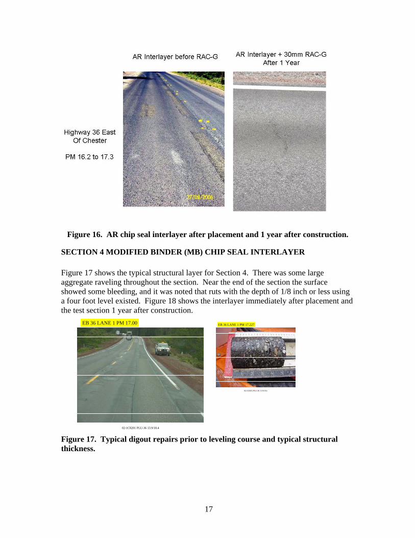
AR Interlayer Test Sections Figure 15 shows the structural section for this section of the roadway. This section is slightly thicker than the sections either before or after this portion of the roadway. Figure 16 shows the AR chip seal immediately after placement and before the RAC-G was placed. After 1 year, Section 3 with the asphalt rubber chip seal interlayer displayed some slight bleeding at the beginning of the section only as with Section 2, there are a limited number of low severity transverse cracks.
02-1C8201 PLU-36 13.9/18.4
EB 36 LANE 1 PM 16.560
02-1C8201 PLU-36 13.9/18.4
WB 36 LANE 1 PM 16.770
Figure 15. Typical structural section in Section 3 (AR chip interlayer).
17
Figure 16. AR chip seal interlayer after placement and 1 year after construction.
SECTION 4 MODIFIED BINDER (MB) CHIP SEAL INTERLAYER Figure 17 shows the typical structural layer for Section 4. There was some large aggregate raveling throughout the section. Near the end of the section the surface showed some bleeding, and it was noted that ruts with the depth of 1/8 inch or less using a four foot level existed. Figure 18 shows the interlayer immediately after placement and the test section 1 year after construction.
02-1C8201 PLU-36 13.9/18.4
EB 36 LANE 1 PM 17.00
02-1C8201 PLU-36 13.9/18.4
EB 36 LANE 1 PM 17.227
Figure 17. Typical digout repairs prior to leveling course and typical structural thickness.

18
MB Immediately After Placement MB After 1 Year
Highway 36 EastOf Chester
PM 17.3 to 18.42
Figure 18. MB chip seal interlayer immediately and 1 year after construction. RAC-G MIX The rubberized asphalt concrete, gap graded, uses the asphalt rubber binder defined in the previous section at between 7% and 9% binder by dry weight of aggregate. The aggregate properties required by the specification are shown in Table 12.
Table 12. Caltrans RAC-G requirements for aggregates
Sieve Size, mm 19.0 mm 100 12.5 mm 90 – 100 9.5 mm 83 – 87 4.75 mm 33 – 37 2.36 mm 18 – 22 1.18 mm -- 0.600 mm 8 – 22 0.075 mm 2 – 7 LA Abrasion, 500 Rev., % Loss 25 Durability Index (CT 229) Fine Agg (Df), Max Coarse Agg (Dc), Max
50 65
Surface Abrasion (CT 360), Max 0.4 g/cm2 Two or More Fractured Faces, % 90

19
SHOULDERS Unfortunately the test sections do not have a consistent paved cross-section. Sections 1 and 2 have approximately 6-ft wide paved shoulders on both sides of the roadway. The shoulders are much narrower, roughly 2.5-ft on each side in the roadway, in Sections 3. Section 4 does not have any paved shoulders. The effects of the lack of lateral support and missing protection from water intrusion in the pavement structure that exists when paved shoulders are narrow or missing must be taken into account when the quality of the interlayers are compared.
SUMMARY The following conclusions can be made 1 year after construction of three interlayer systems:
• All four of the interlayer systems used in these test sections are performing well. There is no evidence of the severe pavement distresses in the old pavement in the new surface.
• The section with only the polypropylene staple fiber is showing a slightly higher severity in transverse cracking, although it is too early in the life of the test sections to determine significant differences between the test sections.
• All other sections are performing well with little to no cracking. The cracking that has developed is intermittent and rarely has cracked across the full width of the travelway.
LESSONS LEARNED A number of lessons can be learned from the construction of these test sections:
• Formal mapping of the type and extent of each test section should be developed prior to the placement of test sections. This will allow researchers to classify cracking as top down due to material properties of the new surface, or from the bottom up (i.e., reflective cracking).
• One person should be designated to collect all of the material property information from either the material supplier.
• Both photographic and written logs of the surface preparation, test section construction, and weather conditions should be kept. It would be best if this was done by the person collecting the material property.
• The uniformity of the leveling course placed using a materials transfer device and a paving screed provide a uniform surface prior to interlayers.

20
RECOMMENDATIONS
• Conduct yearly pavement condition surveys with crack mapping so that the life expectancy of each type of interlayer can be assessed. Factors that need to be considered in any assessment of performance are:
• The original pavement condition differs between the interlayer test sections. The paving mat interlayer section was placed on an existing pavement with an older, somewhat aged, leveling course. The other interlayer systems were placed on a fresh leveling course. The MB chip seal section had the most digouts covered by the leveling course, followed by the interlayer system. Differences between the test sections may be linked to the different conditions of the pavement on which they were placed.
• Perform follow-up FWD testing for comparison of pre- and post-interlayer construction structural differences. It is hoped that any reduction in moisture in the underlying layers will be seen as an increase in the pavement layer stiffness. It is also possible that any spreading of the applied load by the fabric interlayer may be seen as lower deflections in the lower layers.
• The FWD testing should be conducted at the same time of year as the original testing to minimize seasonal influence on the calculated layer stiffness.
REFERENCES Caltrans 1 (2006) www.dot.ca.gov/hq/esc/Translab/fpmcoc.htm Caltrans 2 (2006) www.dot.ca.gov/hq/esc/ctms/index.htm Caltrans Contract No. 02-1C8204 MTAG Chapter 12 Draft - 2008

APPENDIX A
Innovation Pre-Proposal, Proposal, and Final Report Format

- 1 -
Innovation Pre-Proposal, Proposal and Final Report Format Objective The innovative project is located in Plumas County on state route 36 approximately 5 miles east of the City of Chester. The project will compare various non-standard and standard seal coat specifications by applying the specified products then overlaying with rubberized paving grade asphalt concrete. The objective is to determine the cost effectiveness and performance characteristics of first sealing the pavement then overlaying with rubberized asphalt concrete. This strategy is generally referred to as an interlayer. The cost effectiveness will be measured using a life cycle cost analysis based on field performance gained using interlayers compared to typical life cycle cost of pavements placed without interlayers. Performance characteristics will include resistance to reflective cracking, resistance to rutting, and long term performance. These applications are consistence with maintenance efforts to maintain travelways currently in a poor state of repair. The success of this project should assist the Division of Maintenance by providing an additional project that correlates added service life gained by placing an interlayer that seals the existing pavement and absorbs applied stresses. Using a life cycle cost analysis this strategy should provide a less costly, longer lasting pavement maintenance solutions where major rehabilitation are low priority and unlikely for program funding. The following information will provide details of the project. Background There have been a few projects built in California using both 2-layer systems also referred to as interlayer systems. The last project using a 2-layer strategy was sponsored by the near the California Integrated Waste Management Board (Esparto site) constructed in 1992. This Esparto site has provided a clear indicator that by first placing a flexible interlayer that seals the pavement, then overlaying with a thin asphalt concrete can extend the service life of typical maintenance strategies. The Esparto site continues to perform well after 13 years. Caltrans has used interlayers as an integral part of crack seat and overlay rehabilitation strategies. The interlayer served as a stress absorbing membrane interlayer (SAMI) designed to seal and provides a high resistance to reflective cracking. Typically these SAMI’s have been in the form of a rubberized chip seal or a non-woven polyester mat. This project should provide additional documentation of the effectiveness of 2-layer systems.

- 2 -
Elements of the Innovation Pre-proposal Title Plumas-36 2-Layer pavement maintenance test section Contact information Lance Brown, (530) 225-3251 Matt Gowan 530.225-3597 Description This project will place and compare a polyester fiberglass pavement mat and three different chip seal/interlayer strategies on a section of distressed pavement. This location was selected because it will provide a consistent “before” pavement condition for all four strategies. Benefits This project will compare the benefit of additional service life gained by first placing a flexible interlayer material then overlaying with a rubberized asphalt concrete. The strategies used should provide exceptional resistance to reflective cracking. This project should provide pavement managers alternative strategies and measure the performance characteristic of each interlayer material. In addition this will allow a comparison of the effectiveness of overlay only verses the use of a flexible interlayer. This project will effectively maintain a severely distressed pavement in need of rehabilitation at minimal cost and delay. This project will also provide a correlation of other similar interlayer test sites. Selection criteria The pre-project condition of the pavement in this test section is poor. The pavement exhibits moderate to severe alligator cracking, transverse cracking, longitudinal cracking, some wheel rutting, high oxidation and has some areas repaired by grinder digouts. This location will allow the testing of four different maintenance strategies on a poor condition pavement. Specifications Specifications used in this project are a combination of standard and non-standard special provisions (SSP and NSSP). The NSSP used in this project include: Modified Binder Asphalt and Fiberglass polyester paving mat. The SSP used in this project include: Rubberized asphalt Concrete (Type-G) Seal coal (Polymer Modified) Asphalt Rubber Seal Coat

- 3 -
Elements of the Innovation Proposal Note that items 1-7 of the pre-proposal will be included as the first six items of the full proposal. Project Location PLU-36-14.0/18.4(R22.5/R29.6 kp). This test section will be placed on both the east bound and westbound lanes throughout the test section. Test section markers will be placed at the beginning and end points for each strategy. They will be placed 20 ft (6M) from the edge of pavement in the east bound direction. Estimated Costs The engineer’s estimate for this project is $901,000. Potential problems, impacts and remedies This project is a relatively short section with four strategies being tested. As the test is being conducted, any pavement failures will have to be remediated to allow for the smooth flow of traffic through the project area. Warranties Based on the goals of this test section, a warranty is not applicable. The project does not meet current warranty guidelines. Evaluation Plan The evaluation plan will be based on preconstruction data collected, data collected during construction and data collected after construction as described herein. Preconstruction The data collected prior to construction will include, deflection study report, traffic evaluation and counts, 100% pavement condition survey that reflects a quantification of all visual distresses in the pavement and rut data. Coring will be taken to determine type or types of in-situ asphalt concrete and base. In addition a detailed video will be collected of the entire project limit. The video will contain station marking for reference points. Construction A record will be kept per requirements of the contract specifications that include, source of base stock oils, testing of all modified binders, actual spread rates of oil and aggregates, mix design of rubberized asphalt concrete (void, stability, and oil). The testing will include all modified binder viscosity, torsion recovery testing, softening points, Cone penetration, LA rattler, cleanliness value, actual gradations used for screening, and durability. The asphalt concrete will have time of placement, temperature of placement, relative compaction recorded. Post Construction

- 4 -
The post construction plan will be to monitor the visual distress and rutting present using an annual 100% pavement condition survey and traffic study of change to classifications. A final report will be prepared at year 5 that determines the effectiveness with respect to Distress with time and Distress with equivalent ESAL loading. The report will include conclusions and recommendation based on data collected. Elements of the Innovation Final Report Note that items 1-15 of the proposal will be included as the first part of the report. Evaluation Results Test results prior, during and after construction will be presented. Performance Analysis Results will be analyzed and the performance will be compared to current Caltrans practices. Life-Cycle Costs The performance and project costs will be examined for life-cycle costs. It is recommended that the life-cycle costs be compared to current Caltrans practice using the appropriate design lives and discount factors. Future anticipated production costs should be discussed here, also. Conclusions Discuss how the innovation compares to current Caltrans practice. Recommendations Successful innovations should be directed to the appropriate specification committee. Recommendations for improving innovations that “failed” (via the definition set up in step 13) should be described here.
APPENDIX B
Fiberglass/Polyester Paving Mat

- 1 -
- 2 -

- 3 -

- 4 -
- 5 -

- 6 -

- 7 -

APPENDIX C
Asphalt Rubber NSSP

- 1 -
Page 1 of 15 10-1.___ ASPHALT-RUBBER SEAL COAT Asphalt-rubber seal coat shall consist of an application of asphalt-rubber binder and screenings precoated with paving asphalt. Asphalt-rubber seal coat shall conform to the provisions specified for seal coats in Section 37-1, "Seal Coats," of the Standard Specifications and to these special provisions.
GENERAL Attention is directed to "Order of Work" and "Damage Claims" of these special provisions regarding placement of asphalt-rubber seal coat. The Contractor shall furnish a Certificate of Compliance to the Engineer in conformance with the provisions in Section 6-1.07, "Certificates of Compliance," of the Standard Specifications for each material used in the asphalt-rubber binder and the asphalt-rubber binder mixture. When requested by the Engineer, the Contractor shall also submit samples with the Certificates of Compliance. The Contractor shall provide the Engineer a Material Safety Data Sheet (MSDS) for each of the constituent components of the asphalt-rubber binder and for the completed mixture of the asphalt-rubber binder. The Contractor shall provide a Certificate of Compliance for each truck load of crumb rubber modifier (CRM), paving asphalt, and asphalt modifier delivered to the project. The Quality Control Program used by the manufacturer of each ingredient shall include a sampling and testing frequency as shown below:
A. CRM shall be tested except for the grading requirement, at least once for every 225 tonnes with a minimum of once per project. CRM shall be tested for grading for every truck load delivered to the project.
B. Paving asphalt shall be tested at least once for every 180 tonnes of production with a minimum of once per project.
C. Asphalt modifier shall be tested at least once for every 23 tonnes of production with a minimum of once per project.
D. A copy of the laboratory test results for the test parameters specified in these special provisions for CRM, paving asphalt, and asphalt modifier shall be submitted to the Engineer with the Certificate of Compliance for each truck load of individual material delivered to the project.
Certified volume or mass slips shall be delivered to the Engineer for materials supplied.
PAVING ASPHALT Paving asphalt to be used in the asphalt-rubber binder shall be Grade PG 64-16 and shall conform to the provisions in Section 92, "Asphalts," of the Standard Specifications and these special provisions. Paving asphalt Grade PG 64-16 shall not be polymer modified. The paving asphalt for use in asphalt-rubber binder shall be modified with an asphalt modifier.

- 2 -
ASPHALT MODIFIER The asphalt modifier shall be a resinous, high flash point, aromatic hydrocarbon compound and shall conform to the following requirements:
ASPHALT MODIFIER Test Parameter ASTM Designation Requirement
Viscosity, m2/s (10-6) at 100°C D 445 X ± 3* Flash Point, CL.O.C. °C D 92 207 min. Molecular Analysis
Asphaltenes, percent by mass D 2007 0.1 max. Aromatics, percent by mass D 2007 55 min. * The symbol "X" is the viscosity of the asphalt modifier the Contractor proposes to furnish. The value "X" which the Contractor proposes shall be between the limits 19 and 36 and shall be submitted in writing to the Engineer. Any proposed change, requested by the Contractor, in the value "X" shall require a new asphalt-rubber binder design.
The asphalt modifier shall be proportionately added to the paving asphalt at the production site where the asphalt-rubber binder is blended and reacted. Asphalt modifier shall be added at an amount of 2.5 percent to 6.0 percent by mass of the paving asphalt based on the recommendation of the asphalt-rubber binder supplier. The paving asphalt shall be at a temperature of not less than 190°C or more than 226°C when the asphalt modifier is added. If the asphalt modifier is combined with the paving asphalt, before being blended with the CRM, the combined paving asphalt and asphalt modifier shall be mixed by circulation for a period of not less than 20 minutes. This premixing of asphalt modifier and paving asphalt will not be required when all ingredients of the asphalt-rubber binder are proportioned and mixed simultaneously. Asphalt modifier and paving asphalt shall be measured for proportioning with meters conforming to the provisions in Section 9-1.01, "Measurement of Quantities," of the Standard Specifications.
CRUMB RUBBER MODIFIER (CRM) Crumb rubber modifier (CRM) shall consist of a combination of scrap tire CRM and high natural CRM. The scrap tire CRM shall consist of ground or granulated rubber derived from any combination of automobile tires, truck tires or tire buffings. The high natural CRM shall consist of ground or granulated rubber derived from materials that utilize high natural rubber sources. Steel and fiber separation shall be accomplished by any method. Cryogenic separation, if utilized, shall be performed separately from and prior to grinding or granulating. CRM shall be ground or granulated at ambient temperature. Cryogenically produced CRM particles that pass through the grinder or granulator without being ground or granulated, respectively, shall not be used. CRM shall not contain more than 0.01-percent wire (by mass of CRM) and shall be free of other contaminants, except fabric. Fabric shall not exceed 0.05-percent by mass of CRM. The test and method for determining the percent by mass of wire and fabric is available at the Transportation Laboratory, Office of Pavement Consulting Services, Sacramento, California, Telephone (916) 227-7300, and will be furnished to interested persons upon request. A certificate of compliance certifying these percentages shall be

- 3 -
furnished to the Engineer in conformance with the provisions in Section 6-1.07, "Certificates of Compliance," of the Standard Specifications. The length of an individual CRM particle shall not exceed 4.75 mm. The CRM shall be sufficiently dry so that the CRM will be free flowing and will not produce foaming when combined with the blended paving asphalt and asphalt modifier mixture. Calcium carbonate or talc may be added at a maximum amount of 3 percent by mass of CRM to prevent CRM particles from sticking together. The CRM shall have a specific gravity of between 1.1 and 1.2 as determined by California Test 208. Scrap tire CRM and high natural CRM shall be delivered to the production site in separate bags and shall be sampled and tested separately. CRM material shall conform to the following requirements as determined by ASTM Designation: D 297:
SCRAP TIRE CRM HIGH NATURAL CRM Percent Percent
Test Parameter Minimum Maximum Minimum Maximum Acetone Extract 6.0 16.0 4.0 16.0 Rubber Hydrocarbon 42.0 65.0 50.0 — Natural Rubber content 22.0 39.0 40.0 48.0 Carbon Black Content 28.0 38.0 — — Ash Content — 8.0 — —
The CRM for asphalt-rubber binder shall conform to the gradations specified below when tested in conformance with the requirements in ASTM Designation: C 136, except as follows:
A. Split or quarter 100 g ± 5 g from the CRM sample and dry to a constant mass at a temperature of not less than 57°C nor more than 63°C and record the dry sample mass. Place the CRM sample and 5.0 g of talc in a 0.5-L jar. Seal the jar, then shake the jar by hand for a minimum of one minute to mix the CRM and the talc. Continue shaking or open the jar and stir until particle agglomerates and clumps are broken and the talc is uniformly mixed.
B. Place one rubber ball on each sieve. Each ball shall have a mass of 8.5 g ± 0.5 g, have a diameter of 24.5 mm ± 0.5 mm, and shall have a Shore Durometer "A" hardness of 50 ± 5 in conformance with the requirements in ASTM Designation: D 2240. After sieving the combined material for 10 minutes ±1 minute, disassemble the sieves. Material adhering to the bottom of a sieve shall be brushed into the next finer sieve. Weigh and record the mass of the material retained on the 2.36-mm sieve and leave this material (do not discard) on the scale or balance. Observed fabric balls shall remain on the scale or balance and shall be placed together on the side of the scale or balance to prevent the fabric balls from being covered or disturbed when placing the material from finer sieves onto the scale or balance. The material retained on the next finer sieve (2.00-mm sieve) shall be added to the scale or balance. Weigh and record that mass as the accumulative mass retained on that sieve (2.00-mm sieve). Continue weighing and recording the accumulated masses retained on the remaining sieves until the accumulated mass retained in the pan has been determined. Prior to discarding the CRM sample, separately weigh and record the total mass of fabric balls in the sample.

- 4 -
C. Determine the mass of material passing the 75-µm sieve (or mass retained in the pan) by subtracting the accumulated mass retained on the 75-µm sieve from the accumulated mass retained in the pan. If the material passing the 75-µm sieve (or mass retained in the pan) has a mass of 5 g or less, cross out the recorded number for the accumulated mass retained in the pan and copy the number recorded for the accumulated mass retained on the 75-µm sieve and record that number (next to the crossed out number) as the accumulated mass retained in the pan. If the material passing the 75-µm sieve (or mass retained in the pan) has a mass greater than 5 g, cross out the recorded number for the accumulated mass retained in the pan, subtract 5 g from that number and record the difference next to the crossed out number. The adjustment to the accumulated mass retained in the pan is made to account for the 5 g of talc added to the sample. For calculation purposes, the adjusted total sample mass is the same as the adjusted accumulated mass retained in the pan. Determine the percent passing based on the adjusted total sample mass and record to the nearest 0.1 percent:
SCRAP TIRE CRM PERCENTAGE PASSING
Sieve Sizes Gradation Requirements Operating Range Contract Compliance
2.36-mm 100 100 100 2.00-mm 98-100 95-100 90-100 1.18-mm 45-75 35-85 32-88 600-�m 2-20 2-25 1-30 300-�m 0-6 0-10 0-15 150-�m 0-2 0-5 0-10 75-�m 0 0-2 0-5
HIGH NATURAL CRM PERCENTAGE PASSING
Sieve Sizes Gradation Requirements Operating Range Contract Compliance
2.36-mm — — — 2.00-mm 100 100 100 1.18-mm 95-100 92-100 85-100 600-�m 35-85 25-95 20-98 300-�m 10-30 6-35 2-40 150-�m 0-4 0-7 0-10 75-�m 0-1 0-3 0-5
OPERATING RANGE - If the contractor falls outside the operating range for the scrap tire CRM, but stays within the contract compliance limits, the asphalt rubber seal coat represented by the test shall be removed. However, if requested in writing by the contractor and approved by the engineer, the asphalt rubber seal coat may remain in place and the contractor shall pay to the state $250.00 per each test result falling outside the operating range. Each single grading test shall represent 4500 kg of the scrap tire CRM or the amount used in that one day’s production, whichever is less. If the contractor falls outside the operating range for the high natural CRM, but stays within the contract compliance limits the asphalt rubber seal coat represented by the test shall be removed. However, if requested in writing by the contractor and approved by the engineer, the asphalt rubber seal coat may remain in place and the contractor shall pay to the state

- 5 -
$250.00 per each test result falling outside the operating range. Each single grading test shall represent 1540 kg of the high natural CRM or the amount used in that one day’s production, whichever is less. CONTRACT COMPLIANCE - If the contractor falls outside the contract compliance for the scrap tire CRM the asphalt rubber seal coat represented by the test shall be removed. However, if requested in writing by the contractor and approved by the engineer, the asphalt rubber seal coat may remain in place and the contractor shall pay to the state $1100.00 per each test result falling outside the contract compliance limits. Each single grading test shall represent 4500 kg of the scrap tire CRM or the amount used in that one day’s production, whichever is less. If the contractor falls outside the contract compliance for the high natural CRM the asphalt rubber seal coat represented by the test shall be removed. However, if requested in writing by the contractor and approved by the engineer, the asphalt rubber seal coat may remain in place and the contractor shall pay to the state $600.00. Each single grading test shall represent 1540 kg of the high natural CRM or the amount used in that one day’s production, whichever is less.
ASPHALT-RUBBER BINDER Asphalt-rubber binder shall consist of a mixture of paving asphalt, asphalt modifier, and crumb rubber modifier. At least 2 weeks before its intended use, the Contractor shall furnish the Engineer 4 one liter cans filled with the asphalt-rubber binder proposed for use on the project. The Contractor shall supply the Engineer, for approval, a binder formulation and samples of all materials to be used in the asphalt-rubber binder, at least 2 weeks before construction is scheduled to begin. The binder formulations shall consist of the following information:
A. Paving Asphalt and Modifiers
1. Source and grade of paving asphalt. 2. Source and identification (or type) of modifiers used. 3. Percentage of asphalt modifier by mass of paving asphalt. 4. Percentage of the combined blend of paving asphalt and asphalt modifier by
total mass of asphalt-rubber binder to be used. 5. Laboratory test results for test parameters shown in these special provisions.
B. Crumb Rubber Modifier (CRM)
1. Source and identification (or type) of scrap tire and high natural CRM. 2. Percentage of scrap tire and high natural CRM by total mass of the asphalt-
rubber blend. 3. If CRM from more than one source is used, the above information will be
required for each CRM source used. 4. Laboratory test results for test parameters shown in these special provisions.
C. Asphalt-Rubber Binder
1. Laboratory test results of the proposed blend for test parameters shown in these special provisions.

- 6 -
2. The minimum reaction time and temperature.
The method and equipment for combining the paving asphalt, asphalt modifier, and CRM shall be so designed and accessible that the Engineer can readily determine the percentages by mass for each material being incorporated into the mixture. The proportions of the materials, by total mass of asphalt-rubber binder, shall be 79 percent ± 1 percent combined paving asphalt and asphalt modifier and 21 percent ± 1 percent CRM. However, the minimum amount of CRM shall not be less than 20.0 percent. Lower values shall not be rounded up. The CRM shall be combined at the production site and shall contain 76 percent ± 2 percent scrap tire CRM and 24 percent ± 2 percent high natural CRM, by mass. The paving asphalt and asphalt modifier shall be combined into a blended mixture that is chemically compatible with the crumb rubber modifier to be used. The blended mixture shall be considered to be chemically compatible when the mixture meets the requirements for asphalt-rubber binder (after reacting) found in these special provisions. The blended paving asphalt and asphalt modifier mixture and the CRM shall be combined and mixed together at the production site in a blender unit to produce a homogeneous mixture. The temperature of the blended paving asphalt and asphalt modifier mixture shall not be less than 190°C nor more than 226°C when the CRM is added. The combined materials shall be reacted for a minimum of 45 minutes after incorporation of the CRM at a temperature of not less than 190°C or more than 218°C. The temperature shall not be higher than 6°C below the actual flash point of the asphalt-rubber binder. After reacting, and after two consecutive descending readings are recorded, the blended asphalt-rubber binder shall conform to the following requirements:
BLENDED ASPHALT-RUBBER BINDER Requirement
Test Parameter ASTM Test Method Minimum Maximum Cone Penetration @ 25°C, 1/10 mm D 217 25 60 Resilience @ 25°C, Percent rebound D 3407 18 — Field Softening Point, °C D 36 55 88 Viscosity @190°C, Pa • s (x10-3) See Note 1400 2500
NOTE: The viscosity test shall be conducted using a hand held Haake Viscometer Model VT-02 with Rotor 1, 24 mm depth x 53 mm height, or equivalent, as determined by the Engineer. The accuracy of the viscometer shall be verified by comparing the viscosity results obtained with the hand held viscometer to 3 separate calibration fluids of known viscosities ranging from 1000 Pa to 5000 Pa • s (x10-3). The viscometer will be considered accurate if the values obtained are within 300 Pa • s (x10-3) of the known viscosity. The known viscosity value shall be based on the fluid manufacturer's standard test temperature or the test temperature versus viscosity correlation table provided by the fluid manufacturer. All viscometers used on the project shall be verified to be accurate. The test method for determining the viscosity of asphalt-rubber binder using a hand held viscometer is available at the Transportation Laboratory, Office of Pavement Consulting Services, Sacramento, California, Telephone (916) 227-7300. The accuracy verification results shall be provided to the Engineer and shall be certified by a Certificate of Compliance. The Certificate of Compliance shall be furnished to the Engineer in conformance with the provisions in Section 6-1.07, "Certificates of Compliance," of the Standard Specifications.

- 7 -
The Contractor shall provide samples to the Engineer for acceptance testing. All sampling of CRM shall be performed in the presence of the Engineer. The Contractor shall provide a Haake Viscometer, or equivalent, at the production site during the combining of asphalt-rubber binder materials. The Contractor shall take viscosity readings of asphalt-rubber binder from samples taken from the distributor truck a minimum of 45 minutes after incorporation of the CRM. Readings shall be taken at least every hour with not less than one reading for each batch of asphalt-rubber binder. The Contractor shall log these results, including time and asphalt-rubber temperature. A copy of the log shall be submitted to the Engineer on a daily basis. As determined by the Engineer, the Contractor shall either notify the Engineer at least 15 minutes prior to each test or provide the Engineer a schedule of testing times. If required by the Engineer, the Contractor shall perform viscosity testing prior to application. The reacted asphalt-rubber binder shall be maintained at a temperature of not less than 190°C nor more than 218°C. If any of the material in a batch of asphalt-rubber binder is not used within 4 hours after the 45-minute reaction period, heating of the material shall be discontinued. If the asphalt-rubber binder cools below 190°C and is then reheated, it shall be considered a reheat cycle. The total number of reheat cycles shall not exceed 2. The material shall be uniformly reheated to a temperature of not less than 190°C nor more than 218°C prior to use. Additional scrap tire CRM may be added to the reheated binder and reacted for a minimum of 45 minutes. The cumulative amount of additional scrap tire CRM shall not exceed 10 percent of the total binder mass. Reheated asphalt-rubber binder shall conform to the requirements for blended asphalt-rubber binder.
SCREENINGS Screenings shall conform to the provisions in these special provisions and in Section 37-1.02, "Materials," of the Standard Specifications, except that the third, fourth, eighth, and ninth paragraphs of Section 37-1.02 shall not apply. Stockpiling of screenings after preheating and precoating with paving asphalt will not be permitted. Canvas or similar covers that completely cover each load of precoated screenings shall be used during hauling to minimize temperature drop of the precoated screenings. Screenings shall conform to the following grading requirements prior to precoating with paving asphalt:
SCREENINGS GRADING REQUIREMENTS
12.5-mm Medium Maximum Sieve Sizes Percentage Passing
19-mm 100 12.5-mm 85 - 90 9.5-mm 0 - 30 4.75-mm 0 - 5 2.36-mm -- 75-μm 0-2

- 8 -
Screenings shall conform to the following quality requirements immediately prior to preheating:
SCREENINGS QUALITY REQUIREMENTS Test Parameters California Test Requirements
Los Angeles Rattler Loss (100 Revolutions) 211 10 Max. Los Angeles Rattler Loss (500 Revolutions) 211 25 Max. Film Stripping 302 25 Max. Cleanness Value 227 80 Min. Durability 229 52 Min.
Screenings for asphalt-rubber seal coat shall be preheated to between 127°C and 163°C and uniformly coated at a rate of 0.7-percent to one percent by mass of dry aggregate with any of the asphalts specified in the table "Performance Graded Asphalt Binder" in Section 92, "Asphalts," of the Standard Specifications. Screenings shall be coated at a central mixing asphalt concrete plant that has been approved in conformance with the requirements in California Test 109. The exact rate will be determined by the Engineer.
EQUIPMENT The Contractor shall utilize the following equipment for asphalt-rubber seal coat operations:
A. Self-propelled power brooms that clean the existing pavement and remove loose screenings without dislodging screenings set in the asphalt-rubber binder. Gutter brooms or steel-tinned brooms shall not be used;
B. Pneumatic tired rollers conforming to the provisions in Section 39-5.02, "Compacting Equipment," of the Standard Specifications, except that the rollers shall have an air pressure of 690 kPa and maintained so that the air pressure will not vary more than ±35 kPa in each tire. A sufficient number of rollers shall be used so that one complete coverage will be provided in one pass;
C. A self-propelled screenings spreader, equipped with a screenings hopper in the rear, belt conveyors to carry the screenings to the front, and a spreading hopper equipped with full-width distribution auger and spread roll. The screenings spreader shall be capable of providing a uniform screening spread rate over the entire width of the traffic lane in one application;
D. An asphalt heating tank equipped to heat and maintain the blended paving asphalt and asphalt modifier mixture at the necessary temperature before blending with the CRM. This unit shall be equipped with a thermostatic heat control device and a temperature reading device and shall be accurate to within ±3°C and shall be of the recording type;
E. A mechanical mixer for the complete, homogeneous blending of paving asphalt, asphalt modifier, and CRM. Paving asphalt and asphalt modifier shall be introduced into the mixer through meters conforming to the provisions in Section 9-1.01, "Measurement of Quantities," of the Standard Specifications. The blending system shall vary the rate of delivery of paving asphalt and asphalt modifier proportionate with the delivery of CRM. During the proportioning and blending of the liquid ingredients, the temperature of paving asphalt and the asphalt modifier shall not vary more than ±14°C. The paving asphalt feed, the
- 9 -
asphalt modifier feed, and CRM feed shall be equipped with devices by which the rate of feed can be determined during the proportioning operation. Meters used for proportioning individual ingredients shall be equipped with rate-of-flow indicators to show the rates of delivery and resettable totalizers so that the total amounts of liquid ingredients introduced into the mixture can be determined. The liquid and dry ingredients shall be fed directly into the mixer at a uniform and controlled rate. The rate of feed to the mixer shall not exceed that which will permit complete mixing of the materials. Dead areas in the mixer, in which the material does not move or is not sufficiently agitated, shall be corrected by a reduction in the volume of material or by other adjustments. Mixing shall continue until a homogeneous mixture of uniformly distributed and properly blended asphalt-rubber binder of unchanging appearance and consistency is produced. The Contractor shall provide a safe sampling device that delivers a representative sample of the completed asphalt-rubber binder of sufficient size to permit the required tests;
F. An asphalt-rubber binder storage tank equipped with a heating system to maintain the proper temperature of the asphalt-rubber binder and an internal mixing unit that maintains a homogeneous mixture of blended paving asphalt, asphalt modifier, and CRM;
G. A self-propelled truck or trailer mounted distributor, equipped with an internal mixing unit that maintains a homogeneous mixture of blended paving asphalt, asphalt modifier and CRM. The distributor shall have a pump or pumps that sprays asphalt-rubber binder within ±0.25 L/m2 of the specified rate. The distributor shall have a fully circulating spray bar that applies the asphalt-rubber binder without a streaked or otherwise irregular pattern. The distributor shall be equipped with a tachometer, pressure gages, volume measuring devices, and thermometer. The distributor shall have a platform on the rear of the vehicle and an observer shall accompany the distributor. The observer shall ride in such a position that all spray nozzles are in full view and readily accessible for unplugging plugged nozzles, should plugging occur; and
H. Tailgate discharge trucks for hauling screenings shall be equipped with a device to lock onto the hitch at the rear of the screenings spreader. Haul trucks shall be compatible with the screenings spreader so that the dump bed will not push down on the spreader when fully raised or have too short a bed which results in screenings spilling while dumping into the receiving hopper.
I. Scale structures: Where the total load, including live and dead load, of a scale structure is less than 15 tonnes the requirements for under supports for scale bearing points shall be as follows. 1. The structure shall be supported on at least 4 legs. The total load on any one
leg shall be no greater than 100 kPa. 2. The under support shall be structural grade steel with a minimum cross
sectional dimension of 600 mm and a minimum thickness of 25 mm. 3. The entire scale structure, including under supports, shall be constructed with
such rigidity that no movement or deflection is possible during production operations. Only metal shall be used in the scale support structure.
4. The scale structure shall be level throughout the period of device calibration and material production.
- 10 -
5. Adequate drainage shall be provided to prevent saturation of the ground under the scale. The ground under the scale shall remain in a condition which will support 100 kPa at each under support.
6. At the option of the Contractor, the scale structure may be installed pursuant to the provisions of Section 9-1.01, utilizing concrete under supports.
Equipment shall be approved by the Engineer prior to use.
APPLYING ASPHALT-RUBBER BINDER Asphalt-rubber binder shall be applied in conformance with these special provisions and with the provisions for applying asphaltic emulsion in Section 37-1.05, "Applying Asphaltic Emulsion," of the Standard Specifications, except that the second, third, fourth, fifth, ninth, and twelfth paragraphs of Section 37-1.05 shall not apply. Asphalt-rubber binder for asphalt-rubber seal coat shall be applied where shown on the plans at a rate of 2.3 L/m2 to 2.8 L/m2. The exact rate will be determined by the Engineer. Attention is directed to Section 7-1.11, "Preservation Of Property," of the Standard Specifications and "Existing Highway Facilities" of these special provisions regarding protecting highway facilities from seal coat. Asphalt-rubber binder shall be placed upon a clean, dry surface. The pavement surface temperature shall be a minimum of 13°C where asphalt-rubber binder is to be applied. The atmospheric temperature shall be a minimum of 16°C and a maximum of 40°C. Distributor bar height, distribution speed, and shielding materials shall be utilized to reduce the effects of wind upon spray distribution as directed by the Engineer. The Engineer will delay or reschedule work when high, gusting or dirty winds prevent or adversely affect binder or screening application operations. Necessary equipment shall be in position and ready to commence placement operations before starting. The Contractor shall comply with Federal, State, and Local environmental laws, rules, regulations, and ordinances including, but not limited to, air quality requirements. The asphalt-rubber binder shall be applied to the roadway immediately following mixing and reacting and shall be applied at a temperature not less than 196°C nor more than 213°C. Asphalt-rubber binder application shall not be in excess of that which can be covered with screenings within 2 minutes. When placing asphalt-rubber seal coat at intersections, left turn lanes, gore points, and other irregular areas, asphalt-rubber application shall not be in excess of that which can be covered with screenings within 15 minutes. When joining edges against areas with screenings, the joint shall be swept clean of excess screenings prior to the adjacent application of asphalt-rubber binder. Transverse joints of this type shall be constructed by placing roofing paper across and over the end of the previous asphalt-rubber seal coat application. Once the spraying has progressed beyond the paper, the paper shall be removed immediately. The longitudinal joint between adjacent applications of screenings shall coincide with the line between designated traffic lanes. Longitudinal joints shall be overlapped for complete coverage. The overlap shall not exceed 100 mm. At longitudinal joints with screenings, the edge shall be broomed back and blended to eliminate differences in elevation. The joints shall be free from ridges and depressions
- 11 -
and shall have a uniform appearance consistent with the adjacent sealed surface. Defects shall be corrected at the Contractor's expense. Joints between areas of asphalt-rubber binder without screenings shall be made by overlapping asphalt-rubber binder distributions. The excess material shall be properly dispersed by spreading with a squeegee or rake over a larger area of freshly applied asphalt-rubber binder. The application of asphalt-rubber binder to areas not accessible with the distributor bar on the distributor truck shall be accomplished by using pressurized hand wands or other means approved by the Engineer.
SPREADING SCREENINGS Screenings for asphalt-rubber seal coat shall be spread in conformance with the provisions specified for spreading screenings on asphaltic emulsion in these special provisions and in Section 37-1.06, "Spreading Screenings," of the Standard Specifications, except that the first, fifth, sixth, and seventh paragraphs of Section 37-1.06 shall not apply. Following the application of the asphalt-rubber binder, screenings shall be placed over areas receiving asphalt-rubber binder. Screenings for asphalt-rubber seal coat shall be applied at a temperature not less than 107°C and not more than 163°C after applying asphalt-rubber binder. The Contractor shall prevent any vehicle, including construction equipment, from driving on the asphalt-rubber binder prior to application of screenings. Screenings shall be applied at a rate of 15 kg/m2 to 25 kg/m2. The exact rate will be determined by the Engineer. The completed spread rate shall be within 10 percent of the rate determined by the Engineer. The completed surface shall be free of gaps, ridges, depressions or other irregularities caused by the application of the asphalt-rubber seal coat.
FINISHING Asphalt-rubber seal coat shall be finished in conformance with the provisions for finishing screenings spread on asphaltic emulsion in these special provisions and in Section 37-1.07, "Finishing," of the Standard Specifications, except that the second, third, seventh, eighth, and ninth paragraphs of Section 37-1.07 shall not apply. Initial rolling of the asphalt-rubber seal coat shall consist of a minimum of one complete coverage with one or more pneumatic-tired rollers and shall begin within 90 seconds following the placement of the screenings. The distance between the rollers and the screenings spreader shall not exceed 60 m at any time during the spreading of the screenings operations. A minimum of 3 complete coverages as defined in Section 39-6.03, "Compacting," of the Standard Specifications with pneumatic tired rollers, after the initial coverage, shall be made on the asphalt-rubber seal coat. When permitted by the Engineer, the final roller coverage may be made with one steel wheel roller weighing 7.25 tonnes minimum and 9 tonnes maximum. If a steel wheel roller is used, the roller shall be operated in the static mode only.
- 12 -
Sweeping shall be a multi-step operation following final rolling of the screenings. Loose screenings shall be removed from the roadway surface and abutting adjacent areas. Loose screenings shall be disposed of at least 46 m from the nearest waterway. Initial sweeping shall be completed before controlled traffic is permitted on the asphalt-rubber seal coat. Removal of excess screenings shall be completed before uncontrolled traffic is permitted on the completed asphalt-rubber seal coat. Final sweeping shall be done and loose screenings shall be removed without dislodging the screenings set in the asphalt-rubber binder prior to acceptance.
FLUSH COAT Flush coat shall consist of an application of a fog seal coat followed by a sand cover to the surface of asphalt-rubber seal coat. Flush coat shall conform to the provisions in Section 37-1, "Seal Coats," of the Standard Specifications and these special provisions. Flush coat shall be applied to the asphalt-rubber seal coat immediately after initial brooming of the asphalt-rubber seal coat and removal of excess screenings and prior to opening the lane to uncontrolled (not controlled with pilot cars) public traffic.
Fog Seal Coat Asphaltic emulsion (fog seal coat) shall be grade CSS1 or CSS1h or CQS1 as directed by the Engineer. The asphaltic emulsion (fog seal coat) shall be applied at a rate of 0.14- to 0.27-L/m2. The exact rate of application will be determined by the Engineer. Attention is directed to Section 7-1.11, "Preservation Of Property," of the Standard Specifications and "Existing Highway Facilities" of these special provisions regarding protecting the highway facilities from the fog seal coat. During flush coat operations, the surface upon which the flush coat is being applied shall be closed to public traffic. Care shall be taken to avoid tracking fog seal coat material onto existing pavement surfaces beyond the limits of construction.
Sand Cover Sand cover shall be applied immediately following application of the fog seal coat. Sand for sand cover shall conform to the provisions for fine aggregate grading in Section 90-3.03, "Fine Aggregate Grading," of the Standard Specifications and these special provisions. Sand shall not contain clay and shall not contain organic material. Sand shall be spread by means of a self-propelled chip spreader equipped with a mechanical device that will spread the sand at a uniform rate over the full width of a traffic lane in a single application. Sand shall be spread at a rate of 1 kg/m2 to 2 kg/m2. The exact rate will be determined by the Engineer.
MEASUREMENT AND PAYMENT Quantities of asphalt-rubber binder for asphalt-rubber seal coat will be measured in the same manner specified for asphalt in Section 92-1.04, "Measurement," of the Standard Specifications. Quantities of screenings for asphalt-rubber seal coat to be paid for by the tonne will be determined after preheating and precoating with paving asphalt in the same manner

- 13 -
specified for asphalt concrete in Section 39-8.01, "Measurement," of the Standard Specifications. The contract price paid per tonne for asphalt-rubber binder shall include full compensation for furnishing all labor, materials, tools, equipment, and incidentals and for doing all the work involved in furnishing and applying asphalt-rubber binder, complete in place, as shown on the plans, as specified in the Standard Specifications and these special provisions, and as directed by the Engineer. The contract price paid per tonne for screenings (hot-applied) shall include full compensation for furnishing all labor, materials (including paving asphalt for precoating screenings), tools, equipment, and incidentals and for doing all the work involved in furnishing and applying screenings, complete in place, including preparation for seal coat and preheating and precoating screenings, furnishing, placing, maintaining, and removing C6 (Loose Gravel) and W6 (35 MPH) signs and temporary supports or barricades for the signs, as shown on the plans, as specified in the Standard Specifications and these special provisions, and as directed by the Engineer. Sand cover will be measured and paid for in the same manner specified for screenings in Section 37-1.08, "Measurement," and Section 37-1.09, "Payment," of the Standard Specifications. No adjustment in compensation will be made for any increase or decrease in the quantities of asphaltic emulsion (fog seal coat) and sand cover required, regardless of the reason for the increase or decrease. The provisions in Section 4-1.03B, "Increased or Decreased Quantities," of the Standard Specifications shall not apply to the items of asphaltic emulsion (fog seal coat) and sand cover.

APPENDIX D Modified Binder Seal Coat

- 1 -
Page 1 of 8 10-1.16 MODIFIED BINDER SEAL COAT Modified Binder Seal Coat, to be placed from KP 27.99 to KP 29.64, shall consist of an application of a modified binder and screenings (medium, hot-applied) that have been precoated with paving asphalt. Modified binder shall conform to the provisions specified for Medium Type seal coat in Section 37-1, "Seal Coats," of the Standard Specifications and these special provisions. Attention is directed to "Order of Work" and "Damage Claims" of these special provisions.
MODIFIED BINDER At least 2 weeks before its intended use, the Contractor shall furnish the Engineer 4 one-liter cans filled with the modified binder proposed for use on the project. The Contractor shall supply the Engineer, for approval, a binder formulation and samples of all materials to be used in the modified binder, at least 2 weeks before construction is scheduled to begin. The binder formulations shall consist of the following information:
1. Supplier and PG grade of asphalt binder according to AASHTO Designation: M 320.
2. Supplier and identification (or type) of modifiers used. 3. Percentage of asphalt modifier by mass of asphalt. 4. Laboratory test results, from a laboratory holding applicable AASHTO
certification, for test parameters shown in these special provisions. 5. PG grade of modified binder according to AASHTO Designation: M 320.
Modified binder shall be a homogeneous material conforming to the following requirements:

- 2 -
Specification Designation
AASHTO Designation
Test Requirement
Tests on Original Binder Specific Gravity @ 15.5 °C T 228 Report Pounds per Gallon @ 15.5 °C Report Gallons per Ton @ 15.5 °C Report DSR, G*/sin delta @70° C, kPa T 315 2.2 min. Penetration, 4° C, 200g/60s, dmm T 49 25 min. Penetration, 25° C, 100g/5s, dmm T 49 40 – 90 Softening Point, °C T 53 82 min. Flash Point, °C T 48 232 min. Rotational Viscosity @ 163° C, cps T 316 250 – 1000 Elastic Recovery, 25 °C, % T 301 70 min. Chip adhesion, ASTM D 3625 Pass
Tests On Residue from RTFO T 240 Softening Point, °C T 53 Report Mass Loss after RTFO, wt% T 240 0.6 max.
Test on PAV Residue (100° C) (AASHTO Designation PP-1) R 28 BBR, creep stiffness @ -12° C MPa T 313 300 max. BBR, m-value @ -12° C T 313 0.300 min.
A Certificate of Compliance shall be furnished to the Engineer in conformance with the provisions in Section 6-1.07, "Certificates of Compliance," of the Standard Specifications. The certificate shall be current and for the materials delivered to the project. The certificate shall certify that the material, which the certificate represents, conforms to the provisions specified in these special provisions. Test results supporting the Certificate of compliance shall be from a laboratory holding AASHTO certification for tests required.
SCREENINGS Screenings shall consist of broken stone, crushed gravel or both. At least 90 percent by mass of the screenings shall consist of crushed particles as determined by California Test 205. California Test 205, Section D, definition of a crushed particle is revised as follows: "A particle having 2 or more fresh mechanically fractured faces shall be considered a crushed particle." Screenings (medium, hot applied) shall come from the same source as the screenings (hot-applied) and screenings (medium). Screenings shall conform to the following grading requirements prior to pre-coating with paving asphalt.

- 3 -
Medium 9.5-mm max. size Sieve Sizes Percentage Passing 19.0-mm — 12.5-mm 100 9.5-mm 85-100 4.75-mm 0-15 2.36-mm 0-5 1.18-mm — 600-µm — 75-µm 0-2
Representative samples for the Cleanness Value test will be taken immediately prior to preheating the material. Representative samples for grading requirements will be taken prior to precoating with asphalt. Screenings shall be preheated to a temperature between 127°C and 175°C and then precoated with 0.7 to 1.0 percent asphalt by mass of dry aggregate and the contractor shall determine the amount. The pre-coating of screenings shall be performed in an asphalt concrete plant. Stockpiling of screenings after preheating and precoating with asphalt will not be permitted. Canvas or similar covers that completely cover each load of precoated screenings shall be used during hauling to minimize temperature drop of the precoated screenings. Screenings shall be spread when the temperature of the precoated screenings is not less than 105°C. Screenings shall conform to the following quality requirements immediately prior to preheating:
Screenings Quality Requirements Test Parameters California Test Requirements
Los Angeles Rattler Loss (500 Revolutions) 211 25 Max. Film Stripping 302 25 Max. Cleanness Value 227 84 Min. Durability (Dc) 229 52 Min.
EQUIPMENT
The equipment used by the Contractor for modified binder seal coat operations shall conform to the following:
A. Self-propelled power brooms shall clean the existing pavement and remove loose screenings without dislodging screenings set in the modified asphalt binder. Gutter brooms or steel-tined brooms shall not be used.
B. A minimum of 3 operational pneumatic-tired rollers conforming to the provisions specified in Section 39-5.02, "Compacting Equipment," of the Standard Specifications, except that the rollers shall carry a minimum loading of 1360 kg on each wheel and an air pressure of 690 ± 35 kPa in each tire, shall compact the seal coat.
C. A self-propelled screenings spreader, equipped with a screenings hopper in the rear, belt conveyors to carry the screenings to the front, and a spreading shall spread the screenings.

- 4 -
D. A self-propelled computerized rate controlled distributor truck shall be used for applying polymer modified asphalt binder. The distributor truck shall be equipped with a heating unit a pump or pumps that spray the polymer modified asphalt binder within ± 0.15-L/m2 of the specified rate and a fully circulating spray bar that applies the binder without a streaked or otherwise irregular pattern. The distributor truck shall be equipped with a tachometer, pressure gages, volume measuring devices and thermometer and computerized rate control.
E. Trucks for hauling screenings shall be equipped so that screenings can be discharged from the tailgate. Trucks shall be equipped with a device to lock onto the hitch at the rear of the screenings spreader. Haul trucks shall be compatible with the screenings spreader so that the dump bed will not push down on the spreader when fully raised. Haul truck dump beds shall be designed so that, while dumping into the receiving hopper, screenings shall be prevented from spilling on the roadway.
PREPARATION FOR SEAL COAT
Surfaces to receive modified binder shall be prepared in conformance with the provisions specified for preparing surfaces to receive asphaltic emulsion as specified in Section 37-1.04, "Preparation for Seal Coat," of the Standard Specifications.
APPLYING MODIFIED BINDER Modified binder shall be applied in conformance with the provisions specified for applying asphaltic emulsion in Section 37-1.05, "Applying Asphaltic Emulsion," of the Standard Specifications. Modified binder for modified binder seal coat shall be applied where shown on the plans at a rate not to exceed 2.3 L/m2 unless approved by the Engineer. The binder shall be applied when the temperature of the binder is between 165°C and 190°C. The Contractor shall determine the exact application rate of the modified binder and the spread rates in Section 37-1.05 shall not apply. The Contractor shall notify the Engineer of the exact spread rate used and shall be within 5 percent of the selected spread rate. The Contractor shall provide verification of application rates for every 1600 m. Modified binder shall not be applied when weather conditions are unsuitable or when the pavement is damp or wet. Excessive wind is considered an unsuitable weather condition. Modified binder shall be applied only when the atmospheric temperature is 18°C or above and the pavement surface temperature is 26°C or above. Modified binder shall not be applied until sufficient screenings are available to immediately cover the binder being applied.
SPREADING SCREENINGS Screenings for modified binder seal coat shall be spread in conformance with the provisions specified for spreading screenings on asphaltic emulsion in Section 37-1.06, "Spreading Screenings," of the Standard Specifications, except the dampness requirement and the reference to the "breaking" of the emulsion shall not apply. Screenings for modified binder seal coat shall be applied where shown on the plans at a rate not to exceed 21 kg/m2 unless approved by the Engineer.

- 5 -
The Contractor shall determine the exact application rate of the screenings and the spread rates in Section 37-1.06 shall not apply. The Contractor shall notify the Engineer of the exact spread rate used and shall be within 5 percent of the selected spread rate. The Contractor shall provide verification of application rates for every 1600 m. When placing modified binder seal coat at intersections, left turn lanes, gore points, and other irregular areas, modified binder application shall not be in excess of that which can be covered with screenings within 10 minutes. When joining edges against areas with screenings, the joint shall be swept clean of excess screenings prior to the adjacent application of modified binder. Transverse joints of this type shall be constructed by placing roofing paper across and over the end of the previous modified binder seal coat application. Once the spraying has progressed beyond the paper, the paper shall be removed immediately. The longitudinal joint between adjacent applications of screenings shall coincide with the line between designated traffic lanes. Longitudinal joints shall be overlapped for complete coverage. The overlap shall not exceed 100 mm. Joint edges shall be swept clean of overlapping cover material prior to application of adjacent asphalt binder. Reasonable precautions shall be taken to avoid skips and overlaps at joints. Defects shall be corrected at the Contractor's expense. At longitudinal joints with screenings, the edge shall be broomed back and blended to eliminate differences in elevation. The joints shall be free from ridges and depressions and shall have a uniform appearance consistent with the adjacent sealed surface. Defects shall be corrected at the Contractor's expense.
FINISHING Modified binder seal coat shall be finished in conformance with the provisions for finishing screenings spread on asphaltic emulsion in Section 37-1.07, "Finishing," of the Standard Specifications. In addition, the following shall apply:
A. Removal of excess screenings shall be completed before uncontrolled traffic is permitted on the modified binder seal coat
B. Initial rolling of the modified binder seal coat shall consist of a minimum of one complete coverage with three pneumatic-tired rollers and shall begin immediately behind the screenings spreader. The distance between the rollers and the screenings spreader shall not exceed 60 m at any time during the spreading of screenings operations.
C. A minimum of 3 complete coverages, after the initial coverage, shall be made with pneumatic-tired rollers on the modified binder seal coat. Each coverage of the roller shall be as defined in Section 39-6.03, "Compacting," of the Standard Specifications.
D. An initial brooming shall be performed after completion of the final rolling and prior to routing public traffic on the modified asphalt binder seal coat.
E. A minimum of 3 complete coverages, as defined in Section 39-6.03, "Compacting," of the Standard Specifications with pneumatic tired rollers, after the initial coverage, shall be made on the modified binder seal coat. When determined by the Contractor, the final roller coverage may be made with one steel wheel roller weighing 7.25 tonnes minimum and 9 tonnes maximum. If a steel wheel roller is used, the roller shall be operated in the static mode only.

- 6 -
F. Sweeping shall be a multi-step operation following final rolling of the screenings. Loose screenings shall be removed from the roadway surface and abutting adjacent areas. Loose screenings shall be disposed of at least 46 m from the nearest waterway.
FLUSH COAT
Flush coat shall consist of an application of a fog seal coat followed by a sand cover to the surface of modified asphalt binder seal coat. Flush coat shall conform to the provisions in Section 37-1, "Seal Coats," of the Standard Specifications and these special provisions. Flush coat shall be applied to the modified binder seal coat, at the discretion of the Engineer, immediately after initial brooming of the modified binder seal coat and removal of excess screenings and prior to opening the lane to uncontrolled (not controlled with pilot cars) public traffic.
Fog Seal Coat Asphaltic emulsion (fog seal coat) shall be grade CSS1 or CSS1h or CQS1 as determined by the Contractor. Emulsion (fog seal) for modified binder seal coat shall be applied where shown on the plans at a rate not to exceed 0.27-L/m2 unless approved by the Engineer. The Contractor shall determine the exact application rate of the emulsion (fog seal). The Contractor shall notify the Engineer of the exact spread rate used and shall be within 5 percent of the selected spread rate. Attention is directed to Section 7-1.11, "Preservation Of Property," of the Standard Specifications and "Existing Highway Facilities" of these special provisions regarding protecting the highway facilities from the fog seal coat. During flush coat operations, the surface upon which the flush coat is being applied shall be closed to public traffic. Care shall be taken to avoid tracking fog seal coat material onto existing pavement surfaces beyond the limits of construction.
Sand Cover Sand cover shall be applied immediately following application of the fog seal coat. Sand for sand cover shall conform to the provisions for fine aggregate grading in Section 90-3.03, "Fine Aggregate Grading," of the Standard Specifications and these special provisions. Sand shall not contain clay and shall not contain organic material. Sand for modified binder seal coat shall be applied where shown on the plans at a rate not to exceed 2 kg/m2 unless approved by the Engineer. The Contractor shall determine the exact application rate of the sand. The Contractor shall notify the Engineer of the exact spread rate used and shall be within 5 percent of the selected spread rate.
MEASUREMENT AND PAYMENT Quantities of modified binder for modified binder seal coat will be measured in the same manner specified for asphalt in Section 92-1.04, "Measurement," of the Standard Specifications. The contract price paid per tonne for modified binder shall include full compensation for furnishing all labor, materials, tools, equipment, and incidentals and for doing all the

- 7 -
work involved in furnishing and applying modified binder, complete in place, as shown on the plans, as specified in the Standard Specifications and these special provisions, and as directed by the Engineer. Quantities of screenings for modified binder seal coat to be paid for by the tonne will be determined after preheating and precoating with paving asphalt in the same manner specified for asphalt concrete in Section 39-8.01, "Measurement," of the Standard Specifications. The contract price paid per tonne for screenings (medium, hot-applied) shall include full compensation for furnishing all labor, materials (including paving asphalt for precoating screenings), tools, equipment, and incidentals and for doing all the work involved in furnishing and applying screenings, complete in place, including preparation for seal coat and preheating and precoating screenings, furnishing, placing, maintaining, and removing C6 (Loose Gravel) and W6 (35 MPH) signs and temporary supports or barricades for the signs, as shown on the plans, as specified in the Standard Specifications and these special provisions, and as directed by the Engineer. Sand cover will be measured and paid for in the same manner specified for screenings in Section 37-1.08, "Measurement," and Section 37-1.09, "Payment," of the Standard Specifications. No adjustment in compensation will be made for any increase or decrease in the quantities of asphaltic emulsion (fog seal coat) and sand cover required, regardless of the reason for the increase or decrease. The provisions in Section 4-1.03B, "Increased or Decreased Quantities," of the Standard Specifications shall not apply to the items of asphaltic emulsion (fog seal coat) and sand cover.

- 1 -
APPENDIX E Polymer Modified Emulsion Seal Coats

- 1 -
Page 1 of 7 10-1.14 SEAL COAT Seal coat, to be placed from KP 24.45 to 25.76, shall be the medium type and shall conform to the provisions in Section 37-1, "Seal Coats," of the Standard Specifications and these special provisions.
MATERIALS Quality Control Testing
Attention is directed to Section 6-3.02, "Testing By Contractor," of the Standard Specifications. The name of an independent testing laboratory that participates in the AASHTO Proficiency Sample Program shall be submitted to the Engineer for approval at least 10 days before beginning seal coat operations. The independent testing laboratory shall conduct quality control testing on the polymer modified asphaltic emulsion for viscosity, sieve, demulsibility, and torsional recovery properties within 3 days of sampling. The results shall be submitted to the Engineer within 7 days of the receipt of the samples. The Contractor's independent testing laboratory shall conduct the Vialit Test Method for aggregate in Chip Seals, French Chip for the retention requirement and submit a signed copy of a test results report to the Engineer and to Roadway Maintenance at 1120 N Street, MS31, Sacramento Ca, 95814, within 10 days of beginning the seal coat operations. The Vialit Test Method is available at http://www.dot.ca.gov/hq/esc/ctms/index.html. The report will not be considered for acceptability testing.
Polymer Modified Asphaltic Emulsion Asphaltic emulsion for the seal coat shall be Grade PMCRS-2h cationic polymer modified asphaltic emulsion. The polymer used to produce polymer modified asphaltic emulsion shall be an elastomeric polymer. The polymer modified asphaltic emulsion shall be thoroughly circulated in the truck prior to obtaining a sample. The samples shall be taken from the distributor truck at mid-load or from a sampling tap or thief. Before the samples are taken, 4 liters shall be drawn from the sampling device and discarded. Two separate 2-liter samples shall be taken in the presence of the Engineer. The Contractor shall provide one sample to the Contractor's approved independent testing laboratory in an insulated shipping container, within 24 hours of sampling. The second sample shall be given to the Engineer in an insulated shipping container, within 24 hours of sampling. Polymer modified asphaltic emulsion and screenings shall meet a 90 percent retention requirement, when tested in conformance with the requirements in the Vialit Test Method for aggregate in Chip Seals, French Chip. In addition to the Test on Residue from Evaporation Test for asphaltic emulsion grades PMRS2, PMRS2h, PMCRS2 and PMCRS2h in Table 3 of the Requirements for Polymer Modified Asphaltic Emulsion in Section 94-1.04, "Method of Test," of the Standard Specifications, the following shall apply:
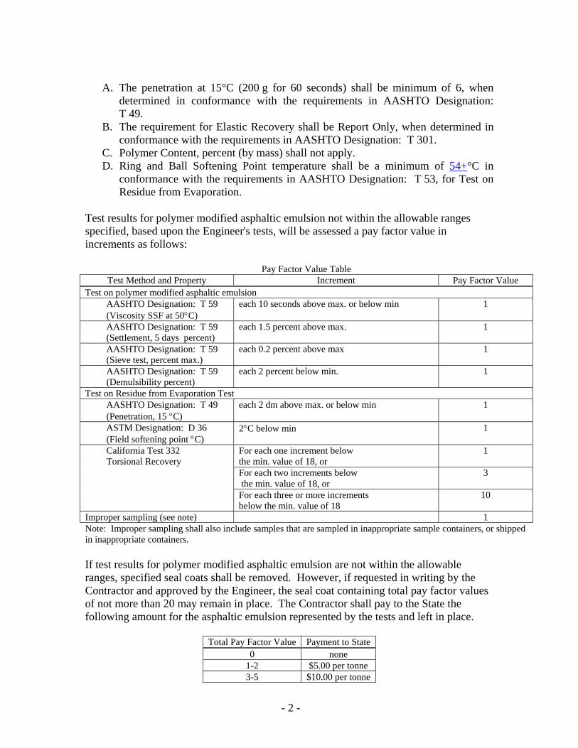
- 2 -
A. The penetration at 15°C (200 g for 60 seconds) shall be minimum of 6, when
determined in conformance with the requirements in AASHTO Designation: T 49.
B. The requirement for Elastic Recovery shall be Report Only, when determined in conformance with the requirements in AASHTO Designation: T 301.
C. Polymer Content, percent (by mass) shall not apply. D. Ring and Ball Softening Point temperature shall be a minimum of 54+°C in
conformance with the requirements in AASHTO Designation: T 53, for Test on Residue from Evaporation.
Test results for polymer modified asphaltic emulsion not within the allowable ranges specified, based upon the Engineer's tests, will be assessed a pay factor value in increments as follows:
Pay Factor Value Table Test Method and Property Increment Pay Factor Value
Test on polymer modified asphaltic emulsion AASHTO Designation: T 59 (Viscosity SSF at 50°C)
each 10 seconds above max. or below min 1
AASHTO Designation: T 59 (Settlement, 5 days percent)
each 1.5 percent above max. 1
AASHTO Designation: T 59 (Sieve test, percent max.)
each 0.2 percent above max 1
AASHTO Designation: T 59 (Demulsibility percent)
each 2 percent below min. 1
Test on Residue from Evaporation Test AASHTO Designation: T 49 (Penetration, 15 °C)
each 2 dm above max. or below min 1
ASTM Designation: D 36 (Field softening point °C)
2°C below min 1
California Test 332 Torsional Recovery
For each one increment below the min. value of 18, or
1
For each two increments below the min. value of 18, or
3
For each three or more increments below the min. value of 18
10
Improper sampling (see note) 1 Note: Improper sampling shall also include samples that are sampled in inappropriate sample containers, or shipped in inappropriate containers. If test results for polymer modified asphaltic emulsion are not within the allowable ranges, specified seal coats shall be removed. However, if requested in writing by the Contractor and approved by the Engineer, the seal coat containing total pay factor values of not more than 20 may remain in place. The Contractor shall pay to the State the following amount for the asphaltic emulsion represented by the tests and left in place.
Total Pay Factor Value Payment to State 0 none
1-2 $5.00 per tonne 3-5 $10.00 per tonne

- 3 -
6-9 $15.00 per tonne 10-14 $25.00 per tonne 15-20 $50.00 per tonne
At least 90 percent by mass of the screenings shall consist of crushed particles as determined by California Test 205. A crushed particle is defined as a particle having 2 or more fresh mechanically fractured faces. Screenings (medium) shall come from the same source as the screenings (medium, hot-applied) and screenings (hot applied). The percentage composition by mass of screenings shall conform to the following grading:
Medium 9.5-mm max. size Sieve Sizes Percentage Passing 19.0-mm — 12.5-mm 100 9.5-mm 85-100 4.75-mm 0-15 2.36-mm 0-5 1.18-mm — 600-µm — 75-µm 0-2
Cleanness Value quality requirement of screenings shall be 84 minimum in conformance with the requirements in California Test 227. Cleanness Value test results for screenings below 86, will require that the seal coat represented by the test shall be removed. However, if requested in writing by the Contractor and approved by the Engineer, seal coat containing screenings with a Cleanness Value below 86, but not less than 75, may remain in place. The Contractor shall pay to the State the following amount for the screenings represented by the test and left in place:
Cleanness Value Payment to State 84or over None 81 – 83 $2.20 per tonne 77-80 $4.40 per tonne 75-76 $6.60 per tonne
When the results of tests for polymer modified asphaltic emulsion and the aggregate grading and Cleanness Value requirements for screenings do not conform to the requirements specified, each payment to the State shall apply. The Department may deduct these amounts from any moneys due, or that may become due, the Contractor under the contract. No single test for polymer modified asphaltic emulsion shall represent more than 50 tonnes or one day's production, whichever is smaller. No single aggregate grading or Cleanness Value test shall represent more than 275 tonnes or one day's production, whichever is smaller.

- 4 -
CONSTRUCTION Polymer modified asphaltic emulsion shall not be placed when the ambient air temperature is expected to fall below 4°C within 24 hours after placement. The maximum length of seal coat operations at any one location, including pilot-car-assisted traffic control, shall be limited to 1.6 kilometers.
FLUSH COAT Flush coat shall consist of an application of a fog seal coat followed by a sand cover to the surface of the seal coat. Flush coat shall conform to the provisions in Section 37-1, "Seal Coats," of the Standard Specifications and these special provisions. Flush coat shall be applied to the seal coat immediately after initial brooming of the seal coat and removal of excess screenings and prior to opening the lane to public traffic.
Fog Seal Coat Asphaltic emulsion (fog seal coat) shall be grade CSS1 or CSS1h or CQS1 as directed by the Engineer. The asphaltic emulsion (fog seal coat) shall be applied at a rate of 0.14- to 0.27-L/m2. The exact rate of application will be determined by the Engineer. Attention is directed to Section 7-1.11, "Preservation Of Property," of the Standard Specifications and "Existing Highway Facilities" of these special provisions regarding protecting the highway facilities from the fog seal coat. During flush coat operations, the surface upon which the flush coat is being applied shall be closed to public traffic. Care shall be taken to avoid tracking fog seal coat material onto existing pavement surfaces beyond the limits of construction.
Sand Cover Sand cover shall be applied immediately following application of the fog seal coat. Sand for the sand cover shall conform to the provisions for fine aggregate grading in Section 90-3.03, "Fine Aggregate Grading," of the Standard Specifications and these special provisions. Sand shall not contain clay and shall not contain organic material. Sand shall be spread by means of a self-propelled chip spreader equipped with a mechanical device that will spread the sand at a uniform rate over the full width of a traffic lane in a single application. Sand shall be spread at a rate of one kg/m2 to 2 kg/m2. The exact spread rate will be determined by the Engineer.
MEASUREMENT AND PAYMENT Full compensation for sampling and testing polymer modified asphaltic emulsion shall be considered as included in the contract price paid per tonne for asphaltic emulsion (polymer modified) and no additional compensation will be allowed therefor. Sand cover will be measured and paid for in the same manner specified for screenings in Section 37-1.08, "Measurement," and Section 37-1.09, "Payment," of the Standard Specifications. No adjustment in compensation will be made for any increase or decrease in the quantities of asphaltic emulsion (fog seal coat) and sand cover required, regardless of the reason for the increase or decrease. The provisions in Section 4-1.03B, "Increased or Decreased Quantities," of the Standard Specifications shall not apply to the items of asphaltic emulsion (fog seal coat) and sand cover.