Embed Size (px)
Citation preview
JURUTERA, October 200510
F E AT U R E
1. INTRODUCTIONStatic load test remains to be unsurpassed
as the engineer’s favorite choice in
determining the geotechnical capacity of a
pile for optimising design and providing
verification of suitability and construct-
ability in the foundation industry.
However, over the past few decades, there
is an obvious lack of innovation in the area
of instrumentation and monitoring for the
classical static load tests, while other
indirect or alternative pile test methods
such as Dynamic Load Tests, Statnamic
Load Tests and Bi-Directional O-Cell Load
Testing had undergone significant
improvement in recent years.
Commonly practiced conventional
bored pile instrumentation method for
static load testing, see Figure 1(a),
normally uses vibrating wire strain gauges
and mechanical tell-tale extensometers
installed and cast within the pile to allow
for monitoring of axial loads and
movements at various levels down the pile
shaft including the pile base level.
Due to lack of innovation in this area,
coupled with the following constraints
and shortcomings, this instrumentation
method had been limited to very few
selected high profile bored pile projects,
and rarely used in driven piles application.
a) Long lead-time and great care are
required, as instrumentation has to be
pre-assembled and installed to steel
cage prior to concreting of pile.
Information on pile length, instrumentation elevation positioning has to be planned and predetermined
Innovation in Instrumented Test Piles in Malaysia:
Application of Global Strain Extensometer
(GloStrExt) Method for Bored Piles.....................................................................................................................................................................................................................
By: Dr H.M. Abdul Aziz bin K.M Hanifah1
and Lee Sieng Kai2
(GIEM)1
Jabatan Kerja Raya Malaysia, Kuala Lumpur, 2
Glostrext Technology Sdn. Bhd., Kuala Lumpur
ABSTRACT
A new instrumentation and analysis technique, called GloStrExt method has recently been introducedfor bored pile load tests. This new technique provides an innovative and improved alternative forconventional bored pile instrumentation methods commonly practiced for the past few decades.Results for five case histories involving full scale static load tests for high capacity bored piles with bothnew and conventional instrumentation details placed in within the same instrumented piles arepresented to demonstrate the advantages of this novel technique. Results show good agreementbetween the new and conventional instrumentation.
Keywords : Static load tests, strain gauges, tell-tale extensometers, global strain extensometers.
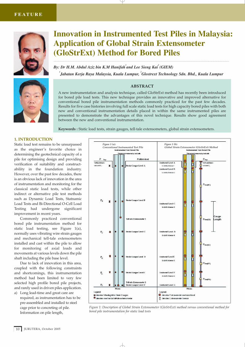
Figure 1 (a): Conventional Instrumented Test Pile
Figure 1 (b): Global Strain Extensometer (GloStrExt) Method
Figure 1: Description of Global Strain Extensometer (GloStrExt) method versus conventional method forbored pile instrumentation for static load tests
JURUTERA, October 200512
F E AT U R E
long before the boring and installation
of test pile.
b) Strain Gauge gives localised strain
measurement, sensitive to variation in
pile cross-section.
c) Sleeved rod tell-tale extensometer
often gives unsatisfactory results due
to rod friction, bowing, eccentricity of
loading and reference beam
movement. The movement for lower
portions of pile shaft is particularly
difficult to be reliably measured most
of the time.
d) When instrumentation levels increases
for particular complex soil strata or
geological structures, it is sometimes
not practical to put tell-tale
extensometers at every levels due to
congestion of sleeved pipes in the
piles, as well as difficulty in
monitoring set-up at pile top.
2. DESCRIPTION OF GloStrExtMETHOD
The GloStrExt Method for static load
testing is a deformation monitoring
system using extensometers with a new
analysis technique for determining axial
loads and movements at various levels
down the pile shaft including the pile base
level. This method is particularly useful
for monitoring pile performance and
optimising pile foundation design.
To appreciate the basic innovation
contained in the GloStrExt Method, the
deformation measurement in the pile by
strain gauges and tell-tale extensometers
are reviewed. Normally, strain gauges
(typically short gauge length) are used for
strain measurement at a particular level or
spot, while tell-tale extensometers
(typically long sleeved rod length) are
used purely for shortening measurement
over an interval (over a length between
two levels). From a ‘strain measurement’
point of view, the strain gauge gives strain
measurement over a very short gauge
length while the tell-tale extensometer
gives strain measurement over a very long
gauge length! Tell-tale extensometer that
measure strain over a very long gauge
length may be viewed as a very large
strain gauge or simply called global strain
extensometer.
With recent advancement in the
manufacturing of retrievable extenso-
meters such as state-of-the-art vibrating
wire extensometers, it is now possible to
measure strain deformation over the entire
length of piles in segments with ease
during static load testing.
Figure 1(b) illustrates typical
arrangement of retrievable vibrating
wire extensometers in test pile,
permitting improved monitoring of
axial loads and movements at various
levels down the pile shaft including the
pile base level using GloStrExt Method.
Generally two strings of retrievable
vibrating wire extensometers with 6 or 7
anchors are adequate to yield improved
results for instrumented static load tests.
This system is equivalent to the
conventional method of using 24 no.
VW Strain Gauges and 6 no. sleeved rod
extensometers, which might not be
possible to be installed satisfactorily due
to congestion in small-sized piles.
3. CASE HISTORIESThe results of five instrumented
sacrificial bored test piles namely PTP1,
PTP2, PTP3, PTP4 and PTP5, involving
full scale static load tests with both new
and conventional instrumentation
details placed within the same piles are
presented. The load tests were
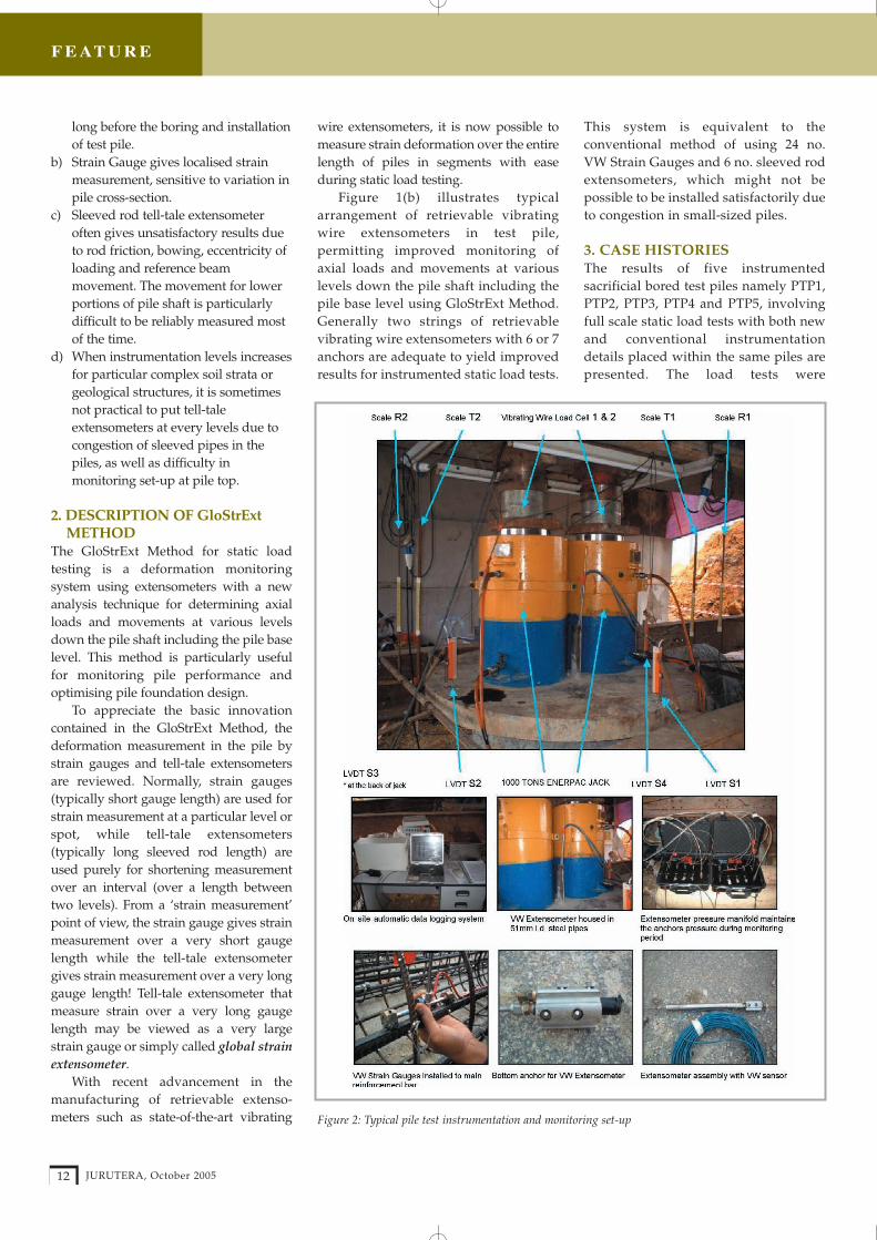
Figure 2: Typical pile test instrumentation and monitoring set-up

JURUTERA, October 200514
F E AT U R E
conducted with great care and control as
described in following subsections. All
the monitoring instruments were
measured automatically during the
loading and unloading cycles using a
data-logger system. Figure 2 gives a
typical illustration for instrumentation
and monitoring set-up.
For the project requirements,
instrumented load tests are conducted to
establish and verify the following for the
use in the design of working piles
which are to be constructed in similar
soil strata and using similar construction
methods: -
(i) To determine the bearing capacity of
the pile and its apportionment into
shaft friction and end bearing;
(ii) To evaluate the design parameters in
relation to the ultimate skin friction
and end bearing, and
(iii) To study the behaviour of pile
settlement and structural shortening
under the applied loads.
3.1 DESCRIPTION OF TEST PILES
3.1.1 Location Of Site And Subsurface
Conditions
The location of the site is at Interchange
No.1 (ICW01), part of Southern Integrated
Gate Project located at Johor Bahru, Johor,
Malaysia. The site is underlain
predominantly by weathered residual
soils, which consist mainly of silty sand. A
typical borehole result is shown in Figure 3.
3.1.2 Piles Instrumentation
For each of the sacrificial bored piles, two
types of instruments, namely, the
Vibrating Wire Strain Gauges and
Vibrating Wire Extensometers were
installed internally in the pile. The strain
gauges were installed at six levels with
four strain gauges at each level. The
Geokon A-9 Vibrating Wire
Extensometers sensors, housed in a
51mm internal diameter sonic logging
pipe was installed at six levels at
corresponding strain gauges levels, with
2 sets per level.
Figure 3 gives a typical arrangement
of instrumentation along the pile depth,
covering both new and conventional
instrumentation details placed in within
the same pile.
3.1.3 Piles Structural Properties
The instrumented test piles PTP1, PTP2,
PTP3, PTP4 and PTP5 constructed were
all bored cast-in-situ reinforced concrete
piles having structural properties as
listed in Table 1.
3.1.4 Procedures for Installation of
Test Piles
The test piles were installed with 12m
length temporary casing with bentonite as
a stabilising fluid. The boring of soil was
carried out with a Bauer BG22 rig.
Figure 3: Instrumentation levels for test pile PTP 1 (750mm dia.) As-built Pile Length = 47.0m
Test Pile Pile Main Circular Concrete ConcretePile No. Diameter Length Reinforcement Links Grade Over-
(mm) (mm) consumption
PTP1 750 47.0 12T20 T12 at 200mm c/c G40/T2 <9%
PTP2 1000 50.5 40T20 T16 at 200mm c/c G40/T2 <14%
PTP3 1000 40.0 40T20 T16 at 200mm c/c G40/T2 <9%
PTP4 750 55.7 12T32 T12 at 200mm c/c G40/T2 <8%
PTP5 750 40.1 20T20 T12 at 200mm c/c G40/T2 <15%
Table 1: Structural properties of piles
Test Pile Pile Date Installed Date of Load Total Loading Maximum No. Diameter Testing Period Test Load
(mm)
PTP1 750 15 Sep 2003 8 to 12 Oct 03 102 hours 6,237 kN
PTP2 1000 22 Sep 2003 16 to 19 Oct 03 61 hours 11,056 kN
PTP3 1000 25 Sep 2003 6 to 10 Nov 03 83 hours 12,500 kN
PTP4 750 27 Sep 2003 29 Nov to 2 Dec 03 85 hours 8,125 kN
PTP5 750 9 Oct 2003 11 to 15 Dec 03 85 hours 8,125 kN
Table 2: Test programs

F E AT U R E
JURUTERA, October 200516
3.1.5 Loading Arrangement And Test
Programmes
The instrumented piles were tested by
the Maintained Load Test (MLT) using a
kentledge reaction system. In the set-up
used, the test loads were applied using
two 1,000 tonne capacity hydraulic
jacks acting against the main reaction
beam. The jacks were operated by an
electric pump. The applied loads were
measured by cali-brated vibrating wire
load cells.
To obtain good quality data, small load
increments were chosen. Typically,
increments of 10% of the working load
were applied prog-ressively in two
loading cycles to a maximum test load of
two and a half times the working load or
failure, whichever occurs first.
3.1.6 Pile Movement And Instruments
Monitoring System
The pile top settlement was monitored
using the following instruments:
(i) Four Linear Variation Displacement
Transducers (LVDTs) mounted to the
reference beams with its plungers
placed vertically against glass plates
fixed on the pile top.
(ii) Vertical scale rules fixed to pile top
sighted by a precise level instrument.
Vertical scales were also provided on
the reference beams to monitor any
movement during load testing.
The vibrating wire load cells, strain
gauges, retrievable extensometers and
LVDTs were logged automatically using
a Micro-10x Datalogger and Multilogger
software, at 3 minutes intervals for close
monitoring during loading and
unloading steps. Only precise level
readings were taken manually.
3.2 RESULTS AND ASSESSMENTOF PILES PERFORMANCE
3.2.1 Load Movement Behaviour Of
The Piles
Measured load movement behaviour of
piles are summarised in Table 3(a) and
Table 3(b).
Typical plots for pile top load versus
pile top settlement, pile top load versus
Test Pile No. Applied Pile Pile Top Pile Base Total Pile Residual PileTop Load Settlement Settlement Shortening Top(1xWL) (mm) (mm) (mm) Settlement
(kN) (mm)
PTP1 2,500 6.34 1.55 4.78 2.16
PTP2 5,000 6.57 0.62 5.95 2.42
PTP3 5,000 3.60 0.02 3.58 0.19
PTP4 3,250 7.89 2.85 5.04 2.40
PTP5 3,250 5.81 1.40 4.41 1.36
Table 3(a): Summary of measured pile settlements and shortening at working load (Cycle 1)
Test Pile No. Maximum Total Pile Top Total Pile Base Total Pile Residual PileApplied Pile Settlement Settlement Shortening Top
Top Loan (mm) (mm) (mm) Settlement(kN) (mm)
PTP1 6,237 75.20 60.18 15.02 62.12
PTP2 11,056 106.46 91.54 14.91 94.04
PTP3 12,500 12.46 0.92 11.54 2.17
PTP4 8,125 28.56 9.10 19.46 10.61
PTP5 8,125 21.59 4.70 16.89 7.01
Table 3(b): Summary of measured pile settlements and shortening at maximum test load (Cycle 2)
Figure 4: Plot of pile top loads (kN) vs pile topsettlement (mm) for 1st and 2nd cycle ofmaintained load testing, PTP 1
Figure 5: Plot of pile top loads (kN) vs pile basesettlement (mm) for 1st and 2nd cycle ofmaintained load testing, PTP 1
Figure 6: Plot of pile top loads (kN) vs shortening(mm) of whole pile for 1st and 2nd cycle ofmaintained load testing, PTP 1

F E AT U R E
JURUTERA, October 200518
pile base settlement and shortening
readings for PTP1 are presented in Figures
4, 5 and 6 respectively.
3.2.2 Axial Load Distribution From VW
Strain Gauges
The load distribution curves indicating the
load distribution along the shaft and at the
base were derived from computations
based on the measured changes in strain
gauge readings and pile properties (steel
content, cross-sectional areas and modulus
of elasticity) based on as-built details
(including concreting record) known from
the construction record.
Load transferred (P) at each level is
calculated as follows:
P = ε (Ec*Ac + Es*As)
where
ε = average change in strain gauge
readings
Ac = cross-sectional area of concrete
Ec = Young's Modulus of Elasticity
in concrete
As = cross-sectional area of steel
reinforcement
Es = Young's Modulus of Elasticity
in steel
= 200 kN/mm2
The Young's Modulus of Elasticity in
concrete, Ec was back-calculated with the
aid of the strain gauge results at level A and
the pile top loads. For each stage of
loading, Ec is back-calculated by assuming
that the load at the strain gauge level A was
equal to the applied load at the pile top.
Typical load distribution curves from
VW Strain Gauges test results for the test
cycle for PTP1 are presented in Figure 7.
3.2.3 Axial Load Distribution From
Retrievable VW Extensometers
In the GloStrExt method, the Young's
Modulus of Elasticity in concrete, Ec was
back-calculated by measuring the strains
in the top 2.0m of debonded length of the
pile using the VW Extensometers and the
pile top loads. For each stage of loading, Ec
is back-calculated by assuming that the
load at the mid-point of the 2.0m
debonded length level was equal to the
applied load at the pile top.
Typical load distribution curves from
GloStrExt test results for the test cycle for
PTP1 are plotted and presented in Figure
8. It is worthy to note that Figures 7 and 8
show very similar characteristics.
3.3 COMPARISON OF RESULTSFROM CONVENTIONAL ANDGloStrExt METHOD
3.3.1 Comparison Of Back Calculated
Concrete Modulus Values
The plots of back-calculated concrete
modulus values versus measured axial
strain at level A from both conventional
strain gauges and Global Strain
Extensometers for the test cycles for 5
piles are plotted and presented in Figure
9. As a practical guide, reference is made
to BS8110 Part 2 (1985) Table 7.2 (for fcu =
40 N/mm2, Ec,28 typical range = 22 to 34
N/mm2) as a comparison to the measured
value.
From the plots presented, it is clear that
the back-calculated concrete modulus
values measured by two independent
systems (conventional Strain Gauges and
Global Strain Extensometers) agree
reasonably well.
These plots are also extremely useful to
study the correction of Ec according to
variation of strain level with pile depth,
which can further improve the accuracy of
the present method of axial load
distribution computation using back-
calculated Ec.
3.3.2 Comparison Of Measured Axial
Strain Along Pile Shaft
The plots of measured axial strain at
various levels along pile shaft from both
conventional strain gauges and Global
Strain Extensometers for 5 piles are
presented in Figures 10 (a) to 10 (e)
respectively.
From the plots presented, it is shown
that the axial strains measured by the
two independent systems are in good
agreement. Considering that the Global
Strain Extensometers measure strains
over an entire section of a pile, thus it
integrates the strains over a larger and
more representative sample than the
conventional strain gauges.
Figure 7: Load distribution curve computed fromVW strain gauges test result, PTP
Figure 8: Load distribution curve computed fromGlobal Strain Extensometer test result, PTP 1
Figure 9: Plot of back-calculated concrete modulus values, Ec vs measured strain from VW Strain Gauges at level A (at 1.0m depth) and GloStrExt (0.0m to 2.0m) for PTP 1, PTP 2, PTP 3, PTP 4 and PTP 5

F E AT U R E
JURUTERA, October 2005 19
4. CONCLUSIONThe results of five instrumented bored test piles involving full-
scale static load tests with both new and conventional
instrumentation show the following behavior:
(i) the back-calculated concrete modulus values measured by
two independent systems (conventional Strain Gauges and Global
Strain Extensometers) agree reasonably well.
(ii) the axial strains measured by the two
independent systems are in good agreement.
The Global Strain Extensometers measure
strains over an entire section of a pile, thus it
integrates the strains over a larger and more
representative sample than the conventional
strain gauges.
Using the global strain extensometers,
measurement of the pile shortening over
the whole pile length can now be reliably
measured in segments. This enables the
movement of the pile and strains at various
levels down the pile shaft to be determined accurately, thus
permitting an improved load transfer distribution of piles in
static load tests.
The GloStrExt method significantly simplifies the
instrumentation effort by enabling the sensors to be post-
installed after casting of pile. It also minimises the risk of
instruments being damaged due to concreting process. �
Figure 10: Plot of Measured Axial Strain from VW Strain Gauges Vs Global Strain Extensometers forPTP 1, PTP 2, PTP 3, PTP 4 and PTP 5
REFERENCES
[1] Chan S.F. (2004) " Design And Construction OfFoundation For Suntec City, Singapore", SpecialLectures, Proceedings Of Malaysian GeotechnicalConference, March 2004.
[2] J.T. Chin (2004) " A Review Of Some PileSettlement Acceptance Criteria" Proceedings OfMalaysian Geotechnical Conference, March 2004.
[3] Jorj Osterberg (1999) "Value Engineering – A GreatConcept. Why Isn’t It Used More Frequently?"Ohio River Valley Soil Seminar, 1999.
[4] M.England (1999) " Fully Automated Pile LoadTest Equipment", Tunnel Construction & Piling 99,London.
[5] "Structural Use Of Concrete" BS 8110: Part 1 : 1985,British Standard Institution.
[6] "Structural Use Of Concrete" BS 8110: Part 2 : 1985,British Standard Institution.
[7] Instruction Manual, Model A-9 RetrievableExtensometer, Geokon Inc.
[8] In-house Pile Load Test Reports, Spectest Sdn.Bhd.