Embed Size (px)
Citation preview
Innovation in gas treatment,
mercury removal, CO2 handling and
other approaches
Introduction
Steve Fogg

Formative Years

1971 – Houston We Have a Problem

A Safe Landing

Our Guest Speaker – Prof Martin Atkins
Chair of Chemical Innovation and Sustainability – Queen’s University of Belfast
Commercial Mentor for Spin Out Companies
P/T Commercial Director of QUILL – Queen’s University Ionic Liquid Laboratories
BP – China Chief Scientist
CTO - Petrona
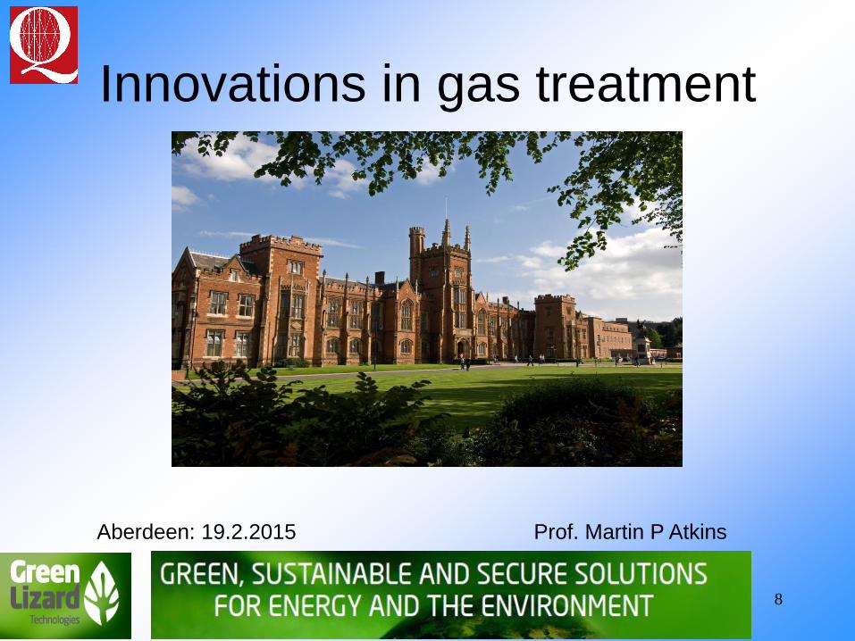
Innovations in gas treatment
8
Aberdeen: 19.2.2015 Prof. Martin P Atkins

Outline Presentation
• Welcome remarks and background
• A fast-track development of Hg removal from
gas
• An emerging technology at demonstration
level for CO2 separation – challenges and
opportunities moving forward
Confidential (Commercially
Sensitive)
9

Confidential (Commercially
Sensitive)
10
10
Technology
Management.
Project
results and
progress
Conceptual
Design studies.
Provisional
CAPEX & OPEX
models
Business
Intelligence;
Market
Studies; BU
Input
TM
D
Fast-track development of a novel Ionic Liquid based Hg
removal technology – in collaboration with PETRONAS
Technology & Engineering Division 6
10
Confidential (Commercially
Sensitive)
11
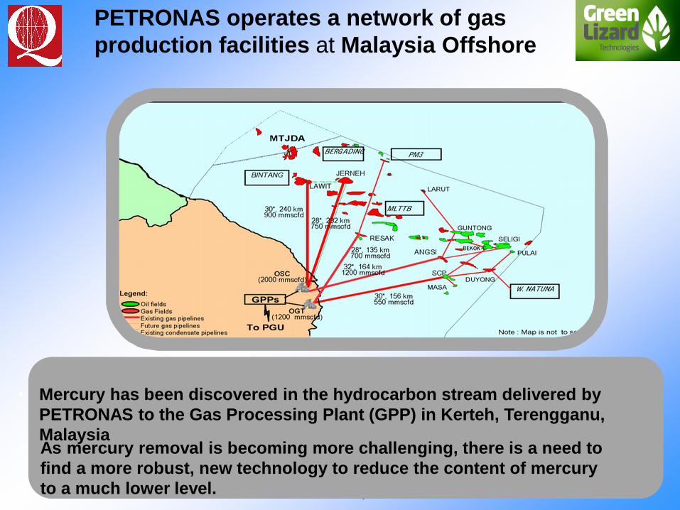
PETRONAS operates a network of gas
production facilities at Malaysia Offshore
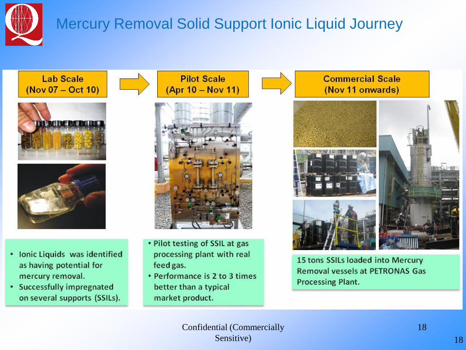
• Mercury has been discovered in the hydrocarbon stream delivered by
PETRONAS to the Gas Processing Plant (GPP) in Kerteh, Terengganu,
Malaysia• As mercury removal is becoming more challenging, there is a need to
find a more robust, new technology to reduce the content of mercury
to a much lower level.
Confidential (Commercially
Sensitive)
12
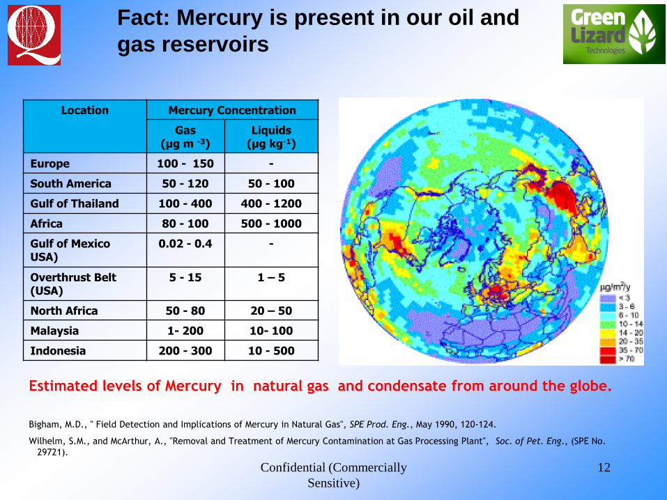
Fact: Mercury is present in our oil and
gas reservoirs
Estimated levels of Mercury in natural gas and condensate from around the globe.
Location Mercury Concentration
Gas (µg m -3)
Liquids(µg kg-1)
Europe 100 - 150 -
South America 50 - 120 50 - 100
Gulf of Thailand 100 - 400 400 - 1200
Africa 80 - 100 500 - 1000
Gulf of Mexico USA)
0.02 - 0.4 -
Overthrust Belt (USA)
5 - 15 1 – 5
North Africa 50 - 80 20 – 50
Malaysia 1- 200 10- 100
Indonesia 200 - 300 10 - 500
Bigham, M.D., " Field Detection and Implications of Mercury in Natural Gas", SPE Prod. Eng., May 1990, 120-124.
Wilhelm, S.M., and McArthur, A., "Removal and Treatment of Mercury Contamination at Gas Processing Plant", Soc. of Pet. Eng., (SPE No.
29721).

Confidential (Commercially
Sensitive)
13
The Problem with Mercury in our Operations- what is it and where is it located?
13

Confidential (Commercially
Sensitive)
14
The effect of mercury is threatening to the oil and gas
industry and hence a mitigation programme has been
developed
Confidential
(Commercially Sensitive)
15
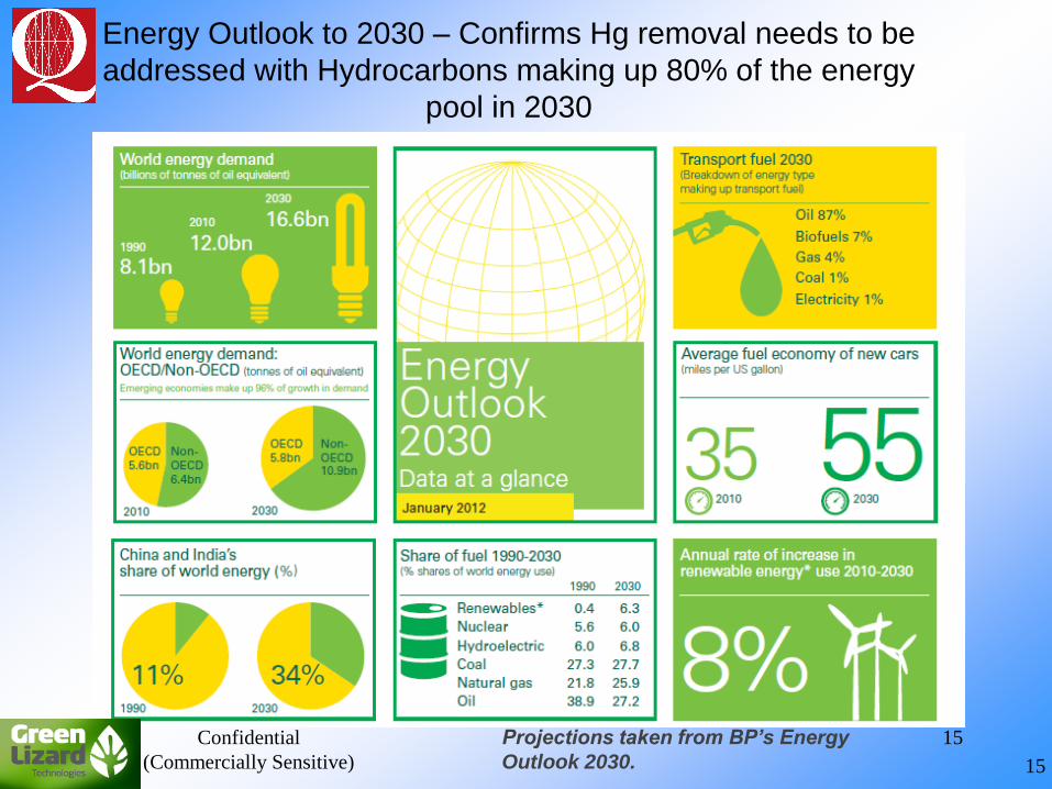
Energy Outlook to 2030 – Confirms Hg removal needs to be
addressed with Hydrocarbons making up 80% of the energy
pool in 2030
15
Projections taken from BP’s Energy
Outlook 2030.
Confidential (Commercially
Sensitive)
16
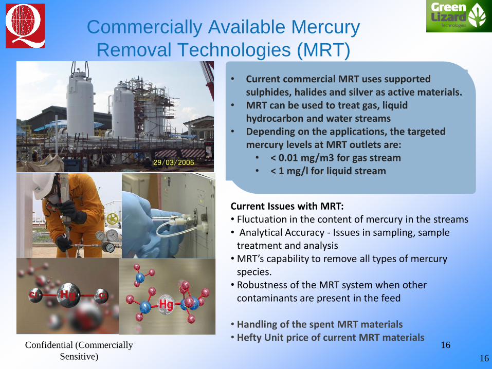
Commercially Available Mercury
Removal Technologies (MRT)
16
• Current commercial MRT uses supported sulphides, halides and silver as active materials.
• MRT can be used to treat gas, liquid hydrocarbon and water streams
• Depending on the applications, the targeted mercury levels at MRT outlets are:
• < 0.01 mg/m3 for gas stream• < 1 mg/l for liquid stream
Current Issues with MRT:• Fluctuation in the content of mercury in the streams• Analytical Accuracy - Issues in sampling, sample
treatment and analysis • MRT’s capability to remove all types of mercury
species.• Robustness of the MRT system when other
contaminants are present in the feed
• Handling of the spent MRT materials• Hefty Unit price of current MRT materials

Confidential (Commercially
Sensitive)
17
The IL Adsorbent Package is Innovative and Proprietary
17
The material has to be resistant to water vapour
The active site is a Nano-engineered by-functionalmoiety comprising a molecular scaffold andactivated metal centre.
The in volatile nature of the IL makes supportedversions robust in plant operation. This approachopens up new avenues of research anddevelopment across catalysis and contaminantsremoval processes.
Confidential (Commercially
Sensitive)
18
Mercury Removal Solid Support Ionic Liquid Journey
18

Confidential (Commercially
Sensitive)
1919
Collaboration with QUILL, Belfast
- Start of collaboration
fundamental research
- Establish PETRONAS Ionic Liquid Laboratory in QUILL
- Additional R&D projects included in the program
- Large scale production and Pilot Plant
- Commercialization of R&D projects
2007
2008-2009
2010
2011
Global
commercial
marketing
alliance
20
Several tasks were studied in parallel primarily to reduce
risks in commercialisation and speed the development
20
A new tool to understand the “ageing profile” and screening of new
supports. High throughput experimentation tools applied and
validated.
Establish the right partnerships early. In our case with catalyst
manufacturers, support providers, ionic liquid manufacturer.
Strong support from site for implementation – commitment through
the organisation
Economics, commercialisation, corrosion, risk management, HSE, Due
Diligence, Patents & IP.
Critical path issues managed by central team drawn together from
manufacturing, technology, engineering and business development.
Key to success was “excellence” in project management. The
difference between success and failure.
Confidential (Commercially
Sensitive)
21
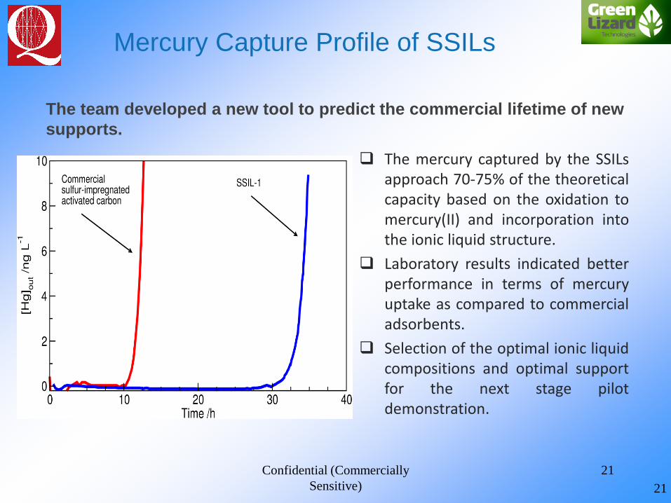
Mercury Capture Profile of SSILs
21
The team developed a new tool to predict the commercial lifetime of new
supports.
The mercury captured by the SSILsapproach 70-75% of the theoreticalcapacity based on the oxidation tomercury(II) and incorporation intothe ionic liquid structure.
Laboratory results indicated betterperformance in terms of mercuryuptake as compared to commercialadsorbents.
Selection of the optimal ionic liquidcompositions and optimal supportfor the next stage pilotdemonstration.

Confidential (Commercially Sensitive) 22
Slip stream pilot plant
22
The heart of the slip stream pilot plant ismultiple reactors fed direct from the mainplant gas feed.
The unit is set-up for “doping extra Hg” toallow adsorption capacity to be estimated(life of the adsorbent).
The unit sees all plant operational variancesand feed gas changes in the main plant.
Multiple beds allows comparison of differentadsorbents
Additional capability and understandinggenerated on site. Early opportunity fortraining on new technology.
Confidential (Commercially
Sensitive)
23
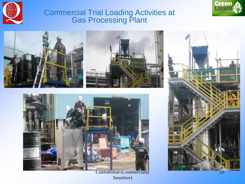
Commercial Trial Loading Activities at Gas Processing Plant
23
Confidential (Commercially
Sensitive)
24
24
It is possible to fast track R&D commercialization. It needs:
1. The “right project” – strategic fit to Company objectives
2. The right partners: catalyst manufacturer; support supplier, fundamental
support, in-house expertise and excellence (eg Petronas Hg analysis)
3. Commitment from industrial partner especially site management and personnel
3. TEAMWORK and FOCUS
An emerging CO2 separation
demonstration project
Confidential (Commercially
Sensitive)
25
Confidential (Commercially
Sensitive)
26
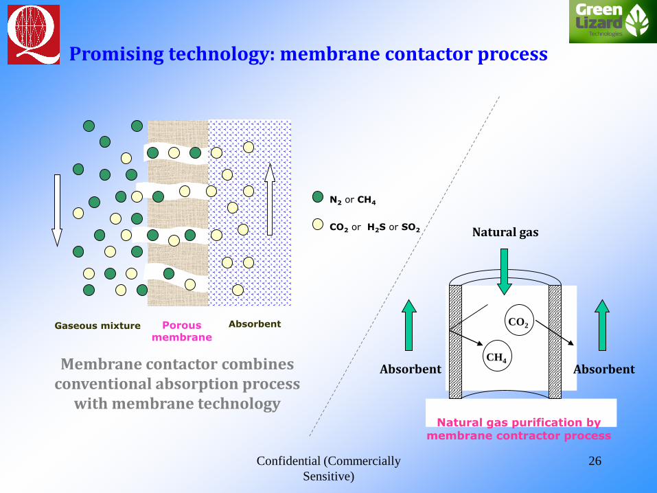
Absorbent Absorbent
Natural gas
CH4
CO2
Natural gas purification by membrane contractor process
Membrane contactor combines conventional absorption process
with membrane technology
Promising technology: membrane contactor process
Porous membrane
Gaseous mixture Absorbent
N2 or CH4
CO2 or H2S or SO2
Confidential (Commercially
Sensitive)
27
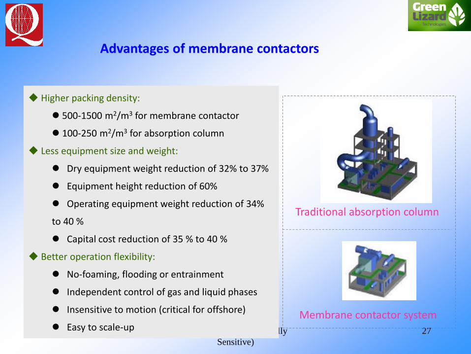
Advantages of membrane contactors
Higher packing density:
500-1500 m2/m3 for membrane contactor
100-250 m2/m3 for absorption column
Less equipment size and weight:
Dry equipment weight reduction of 32% to 37%
Equipment height reduction of 60%
Operating equipment weight reduction of 34%
to 40 %
Capital cost reduction of 35 % to 40 %
Better operation flexibility:
No-foaming, flooding or entrainment
Independent control of gas and liquid phases
Insensitive to motion (critical for offshore)
Easy to scale-up
Traditional absorption column
Membrane contactor system

Confidential (Commercially
Sensitive)
28
Laboratory study
Hollow fiber membranes Membrane contactor testing system
CH4
CO2
LP Mixture
Gas Tank
HP Mixture
Gas Tank
Flash
evaporator
Fresh
Absorbent
tank
HP
Absorbent
Tank
Vacuum line
To GC
Purge
Vacuum
pump
MFC
MFC
PIT
P4
PIT
P3
PIT
P1
PIT
P2
PIT
P9
PIT
P11
LI
PIT
P10
PIT
P8
MFC
PIT
P6
PIT
P7 MFC
Y1
Y2
JI
J2
F1
F2 J3
J4
J5 J6
J7
PIT
P5
J13
Y5
Q5
Y4
W2
Q6
J10
J11
J9Y3J8
Q1
W1
Q3 Q4
F4
F3
Spent
Absorbent
Drum
PIT
PIT
Pulsation
dampener
Confidential (Commercially
Sensitive)
29

Confidential (Commercially
Sensitive)
30
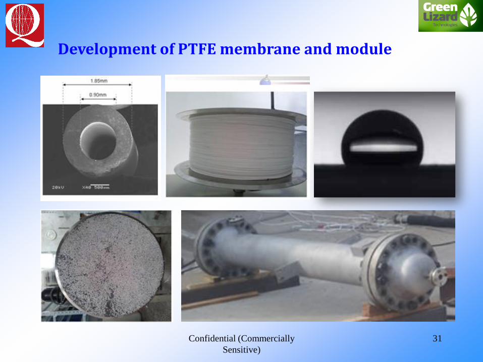
Development of PTFE membranes
• High hydrophobicity
• High chemical resistance
• Wetting resistance
• Good mechanical performance
PTFE is considered one of the most suitable materials for membrane contactor use in
CO2 removal from natural gas
C C
F
F
F
F
n
Confidential (Commercially
Sensitive)
31
Development of PTFE membrane and module

Confidential
(Commercially Sensitive)
32
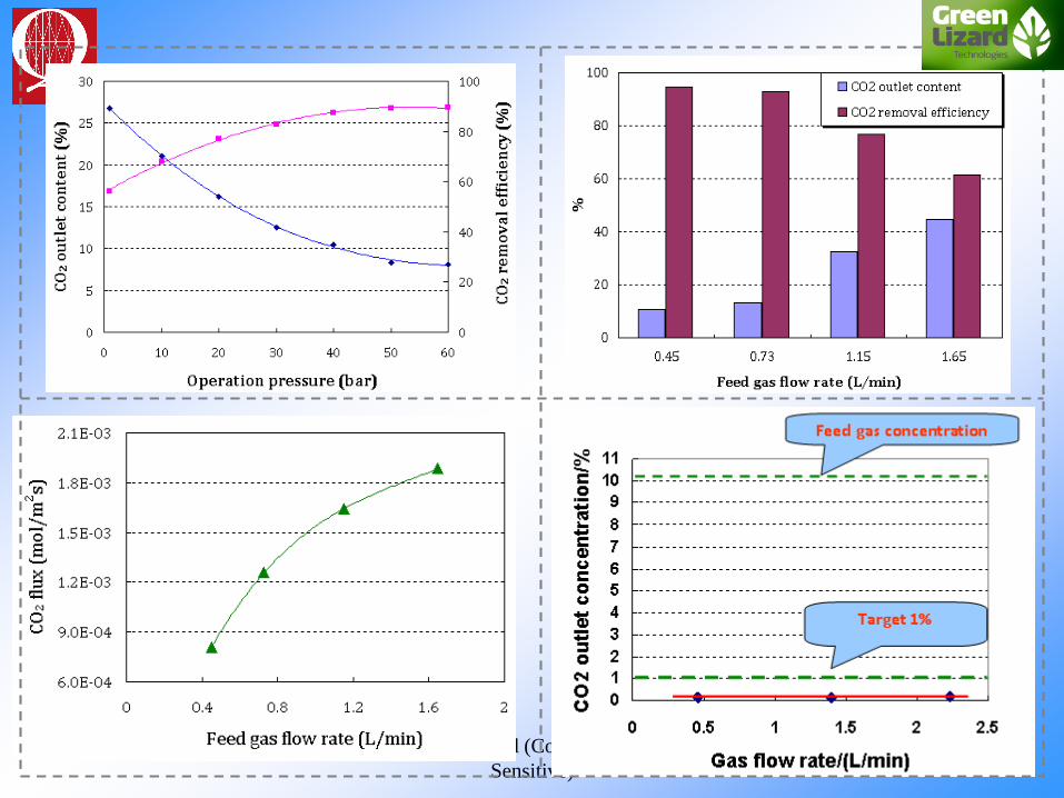
Development of membrane contactor pilot systemThe commissioning for pilot scale hollow fiber membrane contactor on CO2 removal from natural gas was
successfully conducted in a gas process plant located at Malaysia east coast, which is jointly developed by Prof. Cao Group (DNL0905) of Dalian Institute of Chemical Physics CAS (DICP) and PETRONAS.
The system operated continuously and stably for 72 hours, the results indicated that all process parameters met the contract requirements. It is the world`s first system to purify the high pressure natural gas by hollow fiber membrane contactor. The unit adopted firstly the PTFE hollow fiber high-pressure membrane absorber jointly developed by DICP and Shanghai Bi Ke Clean Energy Technology Co., Ltd (“CECC”), the performance indicators of which also satisfied the contract requirements for the membrane development.
Factory Acceptance test: inlet 10 %, outlet <0.1 %
GPP3 on-site test: inlet 5%,outlet 0.02%-0.2%
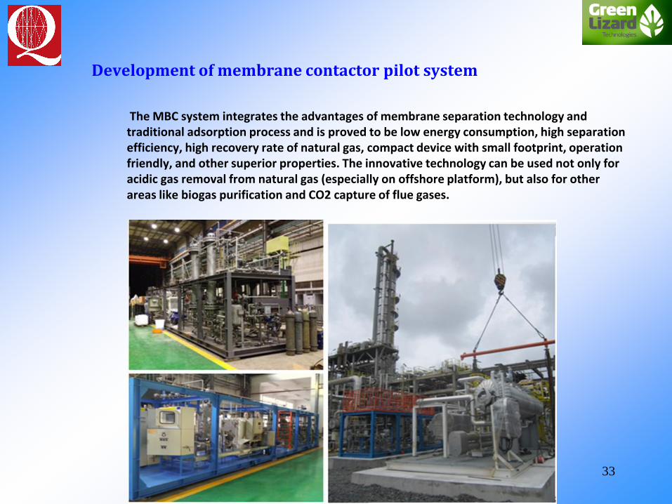
Development of membrane contactor pilot system
The MBC system integrates the advantages of membrane separation technology and traditional adsorption process and is proved to be low energy consumption, high separation efficiency, high recovery rate of natural gas, compact device with small footprint, operation friendly, and other superior properties. The innovative technology can be used not only for acidic gas removal from natural gas (especially on offshore platform), but also for other areas like biogas purification and CO2 capture of flue gases.
Confidential (Commercially
Sensitive)
33

34
Caribbean FLNG 下水 全球第一艘投入商业运营的FLNG,Caribbean FLNG为非自航驳船,2014年11月下水,2015年下半年交付至哥伦比亚投运 144m长,32m宽,0.5mt/a LNG,72亿cf/d,2亿Nm^3/d,90KNm^3/h
Exmar和加拿大Pacific Rubiales Energy公司(PRE)的全资子公司Pacific Midstream Holding各出资50%成立的合资公司所有 惠生海工负责总承包建设 EPCIC,Black & Veatch负责提供工艺技术及工艺设备采购,北京华福负责该工艺生产装置的详细设计
CARIBBEAN 设计参数 吸收塔 40寸MBC
设计处理量/Nm3/h 90000
设计进口CO2含量 ppm 2000 2000
设计出口CO2含量 ppm 50 50
单根膜组件处理量 Nm3/h / 6400
需要数量 1 14
所需膜面积/m2 / 56.25 K
尺寸 Φ1500mm×20.3m Φ1000mm×2.6m
单位设备体积处理量 2510 3135
SHELL设计参数 吸收塔 40寸MBC
设计处理量 Nm3/h 580000
设计进口CO2含量 ppm 2000 2000
设计出口CO2含量 ppm 50 50
单根膜组件处理量 Nm3/h / 6400
需要数量 1 91
所需膜面积m2 / 362.5 K
单位设备体积处理量 / 3135
34

Confidential (Commercially Sensitive)
35
Evaluation
Gas‐liquid contactor
--- Data by PoroGen
Specific surface area
(cm2/cm3)
Volumetric mass transfer
coefficient, (sec)-1
Packed column (Countercurrent) 0.1 –3.5 0.0004 –0.07
Bubble column (Agitated) 1 –20 0.003 –0.04
Spray column 0.1 –4 0.0007 –0.075
Membrane contactor (PEEK) 1 –70 >0.1
• Capital cost by 35 -40%;
• Operating costs of 38% -42%;
• Dry equipment weight of 32% -37%;
• Operating equipment weight of 34% -40%;
• Total operating weight of 44% -50%;
• Footprint requirement of 40%.
Reduction & Savings
--- Data by Aker Process System
• Capex reduction of 35-40% due to smaller equipment, Smaller footprint
(floating LNG is possible)
• Opex savings between 30-40% due to Lower energy requirement for
regeneration, higher pressure operation (less compression
required),Minimal hydrocarbon losses, Reduced foaming
Reduction & Savings
--- Data by WP
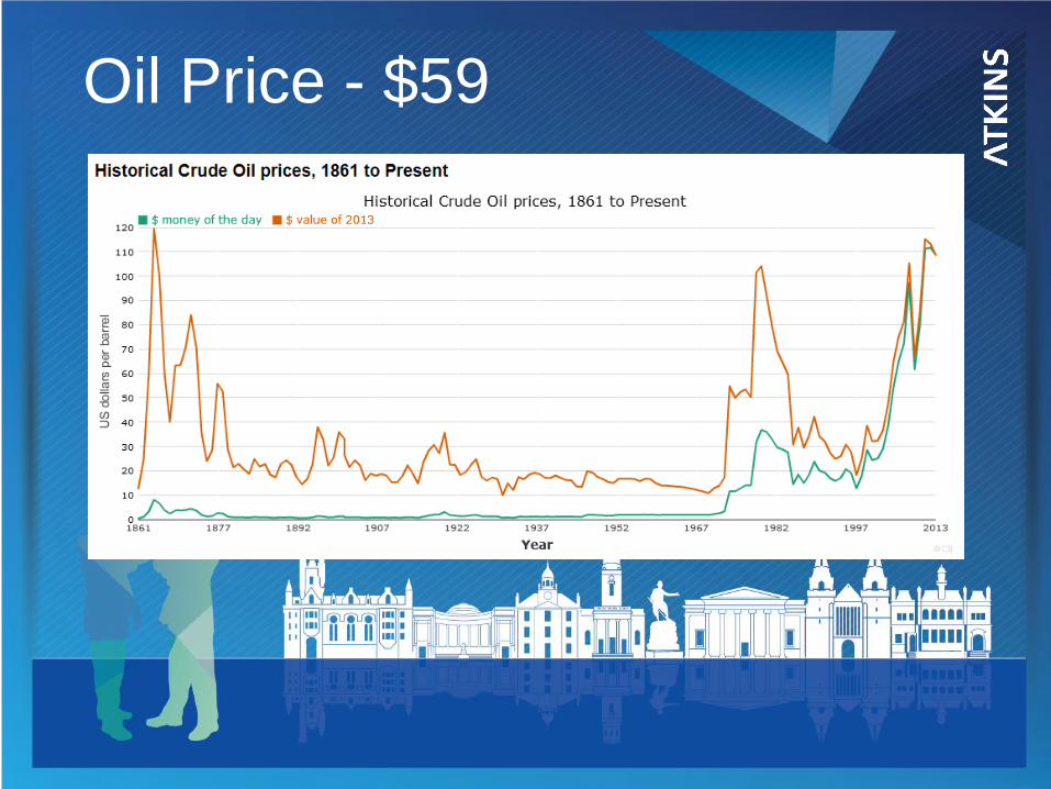
Conclusions
• Despite falling oil prices and uncertainties in the short
term, innovations and improvements to our daily
operations are key for stability and safe, economic
operations
• Gas is proving to be a feedstock of choice for power
and is resilient in the market place with LNG markets
remaining strong and durable in the current crisis
• With remote gas, FLNG production is proving a
useful vehicle for marginal fields.
• The larger gas complexes (e.g. shale) are now taking
advantage of novel gas conversion opportunities.36

Q&A

Thank YouNext event ‘O&G decommissioning: Learning from
other industries’ is on 26 March 2015 at Gordon
Highlander Museum